KR101419807B1 - working tower for minimally invasive surgery system - Google Patents
working tower for minimally invasive surgery systemDownload PDFInfo
- Publication number
- KR101419807B1 KR101419807B1KR1020120100966AKR20120100966AKR101419807B1KR 101419807 B1KR101419807 B1KR 101419807B1KR 1020120100966 AKR1020120100966 AKR 1020120100966AKR 20120100966 AKR20120100966 AKR 20120100966AKR 101419807 B1KR101419807 B1KR 101419807B1
- Authority
- KR
- South Korea
- Prior art keywords
- rod
- delete delete
- screw
- inner tube
- outer tube
- Prior art date
- Legal status (The legal status is an assumption and is not a legal conclusion. Google has not performed a legal analysis and makes no representation as to the accuracy of the status listed.)
- Active
Links
Images


Classifications
- A—HUMAN NECESSITIES
- A61—MEDICAL OR VETERINARY SCIENCE; HYGIENE
- A61B—DIAGNOSIS; SURGERY; IDENTIFICATION
- A61B17/00—Surgical instruments, devices or methods
- A61B17/56—Surgical instruments or methods for treatment of bones or joints; Devices specially adapted therefor
- A61B17/58—Surgical instruments or methods for treatment of bones or joints; Devices specially adapted therefor for osteosynthesis, e.g. bone plates, screws or setting implements
- A61B17/68—Internal fixation devices, including fasteners and spinal fixators, even if a part thereof projects from the skin
- A61B17/70—Spinal positioners or stabilisers, e.g. stabilisers comprising fluid filler in an implant
- A61B17/7074—Tools specially adapted for spinal fixation operations other than for bone removal or filler handling
- A61B17/7076—Tools specially adapted for spinal fixation operations other than for bone removal or filler handling for driving, positioning or assembling spinal clamps or bone anchors specially adapted for spinal fixation
- A61B17/7077—Tools specially adapted for spinal fixation operations other than for bone removal or filler handling for driving, positioning or assembling spinal clamps or bone anchors specially adapted for spinal fixation for moving bone anchors attached to vertebrae, thereby displacing the vertebrae
- A61B17/7079—Tools requiring anchors to be already mounted on an implanted longitudinal or transverse element, e.g. where said element guides the anchor motion
- A—HUMAN NECESSITIES
- A61—MEDICAL OR VETERINARY SCIENCE; HYGIENE
- A61B—DIAGNOSIS; SURGERY; IDENTIFICATION
- A61B17/00—Surgical instruments, devices or methods
- A61B17/56—Surgical instruments or methods for treatment of bones or joints; Devices specially adapted therefor
- A61B17/58—Surgical instruments or methods for treatment of bones or joints; Devices specially adapted therefor for osteosynthesis, e.g. bone plates, screws or setting implements
- A61B17/68—Internal fixation devices, including fasteners and spinal fixators, even if a part thereof projects from the skin
- A61B17/70—Spinal positioners or stabilisers, e.g. stabilisers comprising fluid filler in an implant
- A61B17/7074—Tools specially adapted for spinal fixation operations other than for bone removal or filler handling
- A61B17/7076—Tools specially adapted for spinal fixation operations other than for bone removal or filler handling for driving, positioning or assembling spinal clamps or bone anchors specially adapted for spinal fixation
- A61B17/7077—Tools specially adapted for spinal fixation operations other than for bone removal or filler handling for driving, positioning or assembling spinal clamps or bone anchors specially adapted for spinal fixation for moving bone anchors attached to vertebrae, thereby displacing the vertebrae
- A61B17/708—Tools specially adapted for spinal fixation operations other than for bone removal or filler handling for driving, positioning or assembling spinal clamps or bone anchors specially adapted for spinal fixation for moving bone anchors attached to vertebrae, thereby displacing the vertebrae with tubular extensions coaxially mounted on the bone anchors
- A—HUMAN NECESSITIES
- A61—MEDICAL OR VETERINARY SCIENCE; HYGIENE
- A61B—DIAGNOSIS; SURGERY; IDENTIFICATION
- A61B17/00—Surgical instruments, devices or methods
- A61B17/56—Surgical instruments or methods for treatment of bones or joints; Devices specially adapted therefor
- A61B17/58—Surgical instruments or methods for treatment of bones or joints; Devices specially adapted therefor for osteosynthesis, e.g. bone plates, screws or setting implements
- A61B17/68—Internal fixation devices, including fasteners and spinal fixators, even if a part thereof projects from the skin
- A61B17/70—Spinal positioners or stabilisers, e.g. stabilisers comprising fluid filler in an implant
- A61B17/7074—Tools specially adapted for spinal fixation operations other than for bone removal or filler handling
- A61B17/7083—Tools for guidance or insertion of tethers, rod-to-anchor connectors, rod-to-rod connectors, or longitudinal elements
- A61B17/7085—Tools for guidance or insertion of tethers, rod-to-anchor connectors, rod-to-rod connectors, or longitudinal elements for insertion of a longitudinal element down one or more hollow screw or hook extensions, i.e. at least a part of the element within an extension has a component of movement parallel to the extension's axis
- A—HUMAN NECESSITIES
- A61—MEDICAL OR VETERINARY SCIENCE; HYGIENE
- A61B—DIAGNOSIS; SURGERY; IDENTIFICATION
- A61B17/00—Surgical instruments, devices or methods
- A61B17/56—Surgical instruments or methods for treatment of bones or joints; Devices specially adapted therefor
- A61B17/58—Surgical instruments or methods for treatment of bones or joints; Devices specially adapted therefor for osteosynthesis, e.g. bone plates, screws or setting implements
- A61B17/68—Internal fixation devices, including fasteners and spinal fixators, even if a part thereof projects from the skin
- A61B17/70—Spinal positioners or stabilisers, e.g. stabilisers comprising fluid filler in an implant
- A61B17/7074—Tools specially adapted for spinal fixation operations other than for bone removal or filler handling
- A61B17/7083—Tools for guidance or insertion of tethers, rod-to-anchor connectors, rod-to-rod connectors, or longitudinal elements
- A61B17/7086—Rod reducers, i.e. devices providing a mechanical advantage to allow a user to force a rod into or onto an anchor head other than by means of a rod-to-bone anchor locking element; rod removers
- A—HUMAN NECESSITIES
- A61—MEDICAL OR VETERINARY SCIENCE; HYGIENE
- A61B—DIAGNOSIS; SURGERY; IDENTIFICATION
- A61B17/00—Surgical instruments, devices or methods
- A61B17/56—Surgical instruments or methods for treatment of bones or joints; Devices specially adapted therefor
- A61B17/58—Surgical instruments or methods for treatment of bones or joints; Devices specially adapted therefor for osteosynthesis, e.g. bone plates, screws or setting implements
- A61B17/68—Internal fixation devices, including fasteners and spinal fixators, even if a part thereof projects from the skin
- A61B17/84—Fasteners therefor or fasteners being internal fixation devices
- A61B17/86—Pins or screws or threaded wires; nuts therefor
- A—HUMAN NECESSITIES
- A61—MEDICAL OR VETERINARY SCIENCE; HYGIENE
- A61B—DIAGNOSIS; SURGERY; IDENTIFICATION
- A61B17/00—Surgical instruments, devices or methods
- A61B17/56—Surgical instruments or methods for treatment of bones or joints; Devices specially adapted therefor
- A61B17/58—Surgical instruments or methods for treatment of bones or joints; Devices specially adapted therefor for osteosynthesis, e.g. bone plates, screws or setting implements
- A61B17/88—Osteosynthesis instruments; Methods or means for implanting or extracting internal or external fixation devices
Landscapes
- Health & Medical Sciences (AREA)
- Orthopedic Medicine & Surgery (AREA)
- Neurology (AREA)
- Life Sciences & Earth Sciences (AREA)
- Surgery (AREA)
- Heart & Thoracic Surgery (AREA)
- Engineering & Computer Science (AREA)
- Biomedical Technology (AREA)
- Nuclear Medicine, Radiotherapy & Molecular Imaging (AREA)
- Medical Informatics (AREA)
- Molecular Biology (AREA)
- Animal Behavior & Ethology (AREA)
- General Health & Medical Sciences (AREA)
- Public Health (AREA)
- Veterinary Medicine (AREA)
- Surgical Instruments (AREA)
Abstract
Translated fromKoreanDescription
Translated fromKorean본 발명은 척추용 최소 침습 수술 시스템에 사용되는 작업 타워, 로드 인서터, 로드 리듀서, 인장압축기에 관한 것이다.The present invention relates to a working tower, a rod inserter, a rod reducer, and a tension compressor used in a spinal minimally invasive surgical system.
일반적으로, 척추는 통상 24개(천추골 및 미추골제외)의 뼈로 이루어져 있으며, 자세를 유지할 수 있게 도와줄 뿐만 아니라, 운동의 토대가 되며 내장 기관을 보호하는 중요한 역할을 한다.Generally, the vertebrae are usually composed of 24 bones (except sacrum and submucosa), which not only help maintain posture, but also serve as the basis of exercise and play an important role in protecting the internal organs.
또한, 척추에 가해지는 충격을 흡수하기 위해 각각의 척추 뼈 사이에는 완충 역할을 하는 디스크라 불리는 관절이 위치되고, 그리고 척추 신경이 척추를 관통하며 척추 뼈 마디로 뻗어 있다.In addition, to absorb the impact on the spine, a joint called the disk, which acts as a buffer between each vertebrae, is located, and the spinal nerve passes through the vertebrae and extends to the vertebrae.
이러한 척추의 구조로 인해, 비정상적인 자세가 오랫동안 유지되거나 노화에 따른 퇴행성 질환 또는 외부로부터 충격을 받게 되면, 척추 뼈 마디의 디스크가 손상되어 척추 디스크 질환이 발생할 수 있다. 특히, 이러한 척추 디스크 질환은 척추 신경의 압박으로 통증을 유발하게 된다.Due to the structure of the vertebrae, if the abnormal posture is maintained for a long time, or if a degenerative disease caused by aging or an external shock, the disk of the vertebral bone node may be damaged and the spinal disc disease may occur. In particular, this spinal disc disease causes pain due to compression of the spinal nerve.
이러한 척추 디스크 질환을 치료하기 위해, 시술자는 통상적으로 다음과 같은 수술을 하게 된다.In order to treat such a spinal disc disease, the practitioner usually performs the following operation.
시술자는 척추 뼈의 손상된 부분이 눌리거나 압박되지 않도록 손상된 부위의 디스크를 제거하고, 중공형의 금속 또는 플라스틱 재질로 이루어진 인공 보조물(일예로, 케이지)에 뼈 조각을 채워 디스크를 제거한 부위에 삽입한 다음, 손상된 디스크 상하부위의 척추 뼈의 위치를 교정하는 수술을 하게 된다. 나아가, 척추 뼈의 위치를 교정하기 위해, 시술자는 손상된 디스크 상하부위의 척추 뼈에 교정 스크류를 각각 체결하고, 체결된 교정 스크류를 로드(rod)로 연결하고 나서, 척추 뼈의 위치를 교정한 후, 셋 스크류로 로드와 교정 스크류를 단단히 체결하는 방식을 사용할 수 있다. 따라서, 그 위치가 교정된 척추 뼈 사이에서는 골 융합(fusion)이 정상적으로 이루어지게 된다.The practitioner removes the damaged part of the disk to prevent the injured portion of the vertebrae from being pushed or pressed, and inserts a piece of bone into an artificial auxiliary material (for example, a cage) made of a hollow metal or plastic material, Next, surgery is performed to correct the position of the vertebrae in the upper and lower parts of the damaged disc. Further, in order to correct the position of the vertebrae, the practitioner fixes the corrective screws to the vertebrae of the upper and lower parts of the damaged disk, connects the connected correction screws with a rod, corrects the positions of the vertebrae , And a method of tightly tightening the rod and the calibration screw with the set screw can be used. Therefore, bone fusion is normally performed between the vertebrae where the position is corrected.
이러한 수술 방식은 침습 부위가 커서 환자의 회복을 지연시키고 상처로 인한 수술 만족도가 낮기 때문에 최근에는 척추 수술시 침습 부위를 최소화할 수 있는 최소 침습 수술(Minimally Invasive Surgery) 기법들이 개발되고 있다.Minimally Invasive Surgery techniques have been recently developed to minimize the area of invasion during spinal surgery because of the large size of the invasive site, which slows the patient 's recovery and reduces the satisfaction of the wound.
이러한 최소 침습 수술에 적용 가능하도록 본 출원인에 의해 출원되어 등록된 기술로 한국등록특허공보 제10-0942226호에는 로드 홀더 및 이를 이용하는 척추용 최소 침습 수술 시스템이 개시되어 있다.Korean Registered Patent Application No. 10-0942226, filed by the present applicant and applicable to such minimally invasive surgery, discloses a rod holder and a spinal minimally invasive surgical system using the rod holder.
이러한 종래의 기술은, 도 1a 및 도 1b에 도시된 바와 같이, 환자의 피부[별도의 관통 기구(미도시)를 통해 관통된 환자의 피부]에 삽입되는 것으로 로드(20)를 안내할 뿐만 아니라 척추경 나사못(10)을 파지하는 역할을 하는 로드 가이드(60)와, 로드(20)들 장전하여 로드 가이드(60)의 절개부(61a)에 삽입하는 역할을 하는 로드 홀더(30)와, 로드(20)가 척추경 나사못(10)의 수납홈(11)의 바닥에 맞닿도록 최대한 아래로 누르는 로드 푸셔(70)와, 그리고 로드 가이드(60)의 간격을 조절하는 간격 조절기(도 1b의 95)를 포함한다.This conventional technique not only guides the
하지만, 종래의 로드 가이드(60)는 외부 슬리브(65)의 말단으로부터 돌출된 로드 가압부(65a)에 의해 내부 본체(61)의 파지부(61b)가 외부 슬리브(650) 속으로 완전하게 인입될 수 없는 구조를 가지므로, 그 인입되지 못한 부분으로 인한 파지력 저감을 보상하기 위해 인입되기 전 상태에서의 파지부(61b)의 벌어짐 정도를 최소화하도록 한 구조를 가지고 있어서 시술자가 직접 힘을 가해 척추경 나사못(10)을 파지부(61b)에 억지 끼워야 하는 불편함이 있을 수 있다. 또한, 수술 후, 로드 가이드(60)의 파지부(61b)에 억지 끼워진 척추경 나사못(10)으로부터 원활하게 분리시키기 위해 별도의 로드 가이드 분리기(미도시)가 사용되므로 그 구성이 복잡할 수 있다.However, in the
이와 더불어, 종래의 로드 홀더(30)은 2단 장전 방식으로 작동되도록 구성되어 있어 그 구성이 복잡할 수 있고, 장전부(35)을 올리거나 내리는 별도의 작업과 버튼부(37)를 조작해야 하는 별도의 조작으로 그 사용 방법이 번잡할 수 있다.In addition, since the
나아가, 종래의 로드 푸셔(70)는 척추경 나사못(10)에 셋 스크류(미도시)를 체결하는 기능을 갖고 있지 않아, 즉 로드(20)를 누르는 작업이 셋 스크류 체결과 동시에 이루어질 수 없는 구조여서, 추후 셋 스크류 체결시 로드(20)와 셋 스크류 사이에 조직(tissue)이 낄 우려가 있다. 또한, 종래의 로드 푸셔(70)는 로드 가이드(60)의 중공부로 삽입되는 내장 타입(cannulated type)이 아니라 로드 가이드(60)의 외부에 위치되는 외장 타입이므로 주변 부재와 간섭될 우려가 있다.Further, the
또한, 종래의 간격 조절기(도 1b의 95)는 중심축(pivot)에 해당하는 원통형 봉(95d)이 얇아서 척추경 나사못(10) 사이의 간격을 조절하는데 한계가 있을 수 있다. 또한, 로드 가이드(60)를 파지할 경우 로드 가이드(60)가 원통형 봉(95d)의 길이 방향으로 이동될 우려가 있다. 참고로, 도면 부호 "95a"는 로드 가이드(60)를 파지하는 파지부이고, 도면 부호 "95b" 및 "95c"는 파지부를 조이는 핸들이다.In addition, the conventional spacer 95 (FIG. 1B) may have a limit in adjusting the distance between the
본 발명의 기술적 과제는, 종래의 로드 가이드를 개선하여 교정 스크류를 용이하게 장착할 수 있으며 별도의 분리기 없이 교정 스크류를 쉽게 탈거시킬 수 있는 등 사용이 용이한 작업 타워를 제공하는 것이다.An object of the present invention is to provide a worktool which is easy to use and which can easily mount a calibration screw by improving a conventional rod guide and easily remove a calibration screw without a separate separator.
본 발명의 다른 기술적 과제는, 종래의 로드 홀더를 개선하여 구성이 단순하고 조작이 용이한 로드 인서터를 제공하는 것이다.Another object of the present invention is to provide a rod inserter which is simple in construction and easy to operate by improving the conventional rod holder.
본 발명의 또 다른 기술적 과제는, 종래의 로드 푸셔를 개선하여 로드를 누르면서 교정 스크류에 셋 스크류 체결할 수 있도록 구성하여 로드와 셋 스크류 사이에 조직이 끼는 것을 미연에 막을 수 있고, 타 부재에 삽입되는 타입으로 구성하여 주변 부재와의 간섭을 최소화할 수 있는 로드 리듀서를 제공하는 것이다.Another object of the present invention is to improve a conventional rod pusher so that a set screw can be fastened to a calibration screw while pressing a rod so that a structure can be prevented from being caught between a rod and a set screw, The present invention also provides a load reducer which can minimize the interference with peripheral members.
본 발명의 또 다른 기술적 과제는, 종래의 간격 조절기를 개선하여 교정 스크류 사이의 인장과 압축을 위한 간격 조절 범위를 크게 할 수 있고 중심축에 위치되는 부재가 중심축의 길이 방향으로 이동되지 않도록 한 인장압축기를 제공한다.It is another object of the present invention to provide a method of manufacturing a tension member capable of improving a space adjuster and enlarging a range of adjustment for tension and compression between the calibration screws and reducing the length of the member, Compressor.
상기 목적을 달성하기 위하여, 본 발명의 한 실시예에 따른 작업 타워는 교정 스크류를 파지하며 다른 외부 기기들의 작업대 역할을 하는 작업 타워로서, 외관; 상기 외관의 내부에 슬라이딩 가능하게 구비되는 내관; 상기 외관에 회전 가능하게 연결되고 상기 내관에 나사 체결되어 회전시 상기 내관을 그 길이 방향을 따라 상하 이동시키는 구동 슬리브; 및 상기 내관의 하단부에 구비되며 상기 외관으로부터 인출되면 상기 교정 스크류의 헤드부를 수용할 수 있도록 자체 탄성에 의해 벌어지고 상기 외관으로 인입되면 상기 헤드부를 조일 수 있도록 수축되는 스크류 홀더를 포함한다.In order to accomplish the above object, a work tower according to an embodiment of the present invention is a work tower that grasps a calibration screw and serves as a work platform of other external devices. An inner tube slidably installed inside the outer tube; A driving sleeve rotatably connected to the outer tube and screwed to the inner tube to move the inner tube upward and downward along the longitudinal direction when rotated; And a screw holder provided at a lower end of the inner tube and opened by self-elasticity to receive the head portion of the calibration screw when drawn out of the outer tube, and contracted to tighten the head portion when the outer tube is pulled.
본 발명의 한 실시예에 따른 로드 인서터는 로드를 파지하여 상기 로드를 적어도 두 개의 교정 스크류의 로드 수납부에 안착시키는 로드 인서터로서, 고정 바; 상기 고정 바에 슬라이딩 가능하게 구비되는 이동 바; 상기 고정 바에 회전가능하게 연결되고 상기 이동 바에 나사 체결되어 회전을 통해 상기 이동 바의 이동 거리를 조절하는 조절 노브; 및 상기 고정 바의 일단과 상기 이동 바의 일단과의 사이에 구비되며 상기 이동 바의 이동에 따라 로드를 파지하는 로드 홀더를 포함한다.A rod inserter according to an embodiment of the present invention is a rod inserter for grasping a rod to seat the rod on a rod receiving portion of at least two calibration screws, A movable bar slidably mounted on the fixed bar; A control knob rotatably connected to the fixing bar and screwed to the moving bar to adjust a moving distance of the moving bar through rotation; And a rod holder provided between one end of the fixed bar and one end of the movable bar and holding the rod according to the movement of the movable bar.
본 발명의 한 실시예에 따른 로드 리듀서는, 교정 스크류의 로드 수납부에 안착된 로드를 아래로 누르면서 상기 로드 수납부에 셋 스크류를 체결하는 로드 리듀서로서, 하단부에 셋 스크류 장착부가 형성되는 관 형상의 외측 부재; 상기 외측 부재의 내부에 슬라이딩 가능하게 구비되며 상기 로드에 접하도록 하단에는 상기 외측 부재로부터 인출된 상태의 하단 인출부를 갖는 내측 부재; 및 상기 교정 스크류를 파지한 제3 외부 기기에 체결되는 동안 상기 내측 부재를 하강시켜 상기 로드가 상기 내측 부재의 상기 하단 인출부에 의해 눌리도록 하는 체결용 가압 슬리브; 및 상기 셋 스크류가 상기 교정 스크류의 상기 로드 수납부에 나사 체결되도록 상기 외측 부재를 회전시키는 회전 핸들을 포함한다.The rod reducer according to an embodiment of the present invention is a rod reducer for fastening a set screw to the rod receiving portion while pressing down the rod seated on the rod receiving portion of the calibration screw, ; An inner member slidably provided in the outer member and having a lower end drawn out from the outer member at a lower end to be in contact with the rod; And a fastening pressure sleeve for lowering the inner member while being fastened to the third external device holding the calibration screw so that the rod is pressed by the lower end withdrawing portion of the inner member; And a rotation handle for rotating the outer member such that the set screw is screwed to the rod receiving portion of the calibration screw.
본 발명의 한 실시예에 따른 인장압축기는, 제1 및 제2 작업 타워의 각 하단에 있는 제1 및 제2 교정 스크류 사이를 벌려 인장시키거나 좁혀 압축시키는 인장압축기로서, 상기 제1 및 제2 작업 타워 사이에 위치되는 중심축; 상기 중심축의 일단에 구비되며 상기 중심축을 기준으로 상기 제1 및 제2 작업 타워가 기울어지도록 상기 제1 및 제2 작업 타워를 가압하는 타워 가압 유닛; 및 상기 중심축의 타단에 회전 가능하게 구비되어 상기 제1 및 제2 작업 타워가 상기 중심축의 길이 방향으로 이동되는 것을 막아주는 타워 받침대를 포함한다.A tension compressor according to an embodiment of the present invention is a tension compressor that stretches or narrows and compresses between first and second calibration screws at the lower ends of first and second operation towers, A central axis located between the working towers; A tower pressurizing unit provided at one end of the central shaft and pressing the first and second operation towers so that the first and second operation towers are tilted with respect to the central axis; And a tower pedestal rotatably provided at the other end of the central axis to prevent the first and second operation tows from moving in the longitudinal direction of the central axis.
본 발명의 제1 실시예에 따른 작업 타워에 의하면, 종래의 로드 가이드에 비해 교정 스크류를 용이하게 장착할 수 있으며 별도의 분리기 없이 교정 스크류를 쉽게 탈거시킬 수 있는 등 사용이 용이할 수 있다.According to the operation tower of the first embodiment of the present invention, the calibration screw can be easily mounted as compared with the conventional rod guide, and the calibration screw can be easily removed without using a separate separator.
본 발명의 제2 실시예에 따른 로드 인서터에 의하면, 종래의 로드 홀더에 비해 구성이 단순하고 조작이 용이할 수 있다.According to the rod inserter according to the second embodiment of the present invention, the configuration is simple and easy to operate as compared with the conventional rod holder.
본 발명의 제3 실시예에 따른 로드 리듀서에 의하면, 종래의 로드 푸셔와 달리 로드를 누르면서 교정 스크류에 셋 스크류 체결할 수 있도록 구성하여 로드와 셋 스크류 사이에 조직이 끼는 것을 미연에 막을 수 있고, 타 부재에 삽입되는 타입으로 구성하여 주변 부재와의 간섭을 최소화할 수 있다.The rod reducer according to the third embodiment of the present invention is configured so that the rod can be fastened to the calibration screw while pressing the rod unlike the conventional rod pusher, thereby preventing the tissue from being caught between the rod and the set screw, It is possible to minimize the interference with the peripheral members by constituting a type which is inserted into other members.
본 발명의 제4 실시예에 따른 인장압축기에 의하면, 종래의 간격 조절기에 비해 교정 스크류 사이의 인장과 압축을 위한 간격 조절 범위를 크게 할 수 있고 중심축에 위치되는 부재가 중심축의 길이 방향으로 이동될 수 있는 우려를 미연에 차단할 수 있다.According to the tension compressor of the fourth embodiment of the present invention, compared with the conventional gap adjuster, the interval adjustment range for tension and compression between the calibration screws can be made larger, and the member located on the center axis can be moved You can block the concerns you may have.
도 1a 및 도 1b는 종래의 척추용 최소 침습 수술 시스템을 이루는 각각의 기기들을 나타낸 사시도이다.
도 2는 본 발명의 제1 실시예에 따른 작업 타워를 나타낸 사시도이다.
도 3은 도 2의 작업 타워가 분지된 상태를 보인 단면도이다.
도 4는 도 3의 상태에서 파지부가 인입된 상태를 나타낸 종단면도이다.
도 5는 도 2의 작업 타워 중 외관의 내면을 나타내기 위한 단면도이다.
도 6은 도 3의 작업 타워를 VI-VI 선으로 잘라서 본 단면도이다.
도 7은 본 발명의 제2 실시예에 따른 로드 인서터를 나타낸 사시도이다.
도 8은 도 7의 로드 인서터의 정면도이다.
도 9는 도 8의 로드 인서터를 IX-IX 선으로 잘라서 본 단면도이다.
도 10은 도 8의 "A"부의 평면도이다.
도 11은 도 8의 로드 인서터를 XI-XI 선으로 잘라서 본 단면도이다.
도 12는 도 8의 로드 인서터를 XII-XII 선으로 잘라서 본 단면도이다.
도 13a 및 도 13b는 도 7의 로드 인서터가 로드 중심부를 파지하기 전 및 후 상태를 나타낸 도면이다.
도 14는 도 7의 로드 인서터가 로드 중심부를 파지한 상태에서 작업 타워의 로드 안내홈에 로드를 삽입한 상태를 나타낸 개략적 사시도이다.
도 15a 및 도 15b는 도 7의 로드 인서터가 로드 단부를 파지하기 전 및 후 상태를 나타낸 도면이다.
도 16은 도 7의 로드 인서터가 로드 단부를 파지한 상태에서 작업 타워의 로드 안내홈에 로드를 삽입한 상태를 나타낸 개략적 사시도이다.
도 17은 본 발명의 제2 실시예의 변형례에 따른 로드 인서터를 나타낸 정면도이다.
도 18은 도 17의 로드 인서터의 로드 홀더를 나타낸 사시도이다.
도 19는 도 17의 로드 인서터에 커버가 장착된 상태를 나타낸 사시도이다.
도 20은 도 19의 로드 인서터의 정면도이다.
도 21은 도 20의 로드 인서터의 요부를 절개하여 나타낸 도면이다.
도 22는 도 19의 로드 인서터에 로드가 장착되고 있는 상태를 나타낸 사시도이다.
도 23은 도 19의 로드 인서터에 로드가 장착된 상태를 나타낸 사시도이다.
도 24는 도 23의 상태에서 로드 인서터의 커버가 클립 측으로 이동되어 클립이 잠긴 상태를 나타낸 사시도이다.
도 25는 도 24의 상태에서 조절 노브의 회전으로 이동 바가 클립 측으로 이동되면서 로드가 회전되는 상태를 나타낸 사시도이다.
도 26은 본 발명의 제3 실시예에 따른 로드 리듀서를 나타낸 사시도이다.
도 27은 도 26의 로드 리듀서의 종단면도이다.
도 28은 체결 슬리브가 회전되는 동안 내측 부재의 하단 인출부에 의해 로드를 눌려지고 있는 상태를 나타낸 개략적 단면도이다.
도 29는 회전 핸들이 눌리면서 회전되는 동안 셋 스크류가 교정 스크류의 로드 삽입부에 체결되고 있는 상태를 나타낸 개략적 단면도이다.
도 30은 본 발명의 제4 실시예에 따른 인장압축기를 나타낸 사시도이다.
도 31은 도 30의 인장압축기의 평면도이다.
도 32는 도 30의 인장 압축기의 정면도이다.
도 33은 도 31의 인장 압축기를 XXXIII-XXXIII 선으로 잘라서 본 단면도이다.
도 34는 도 32의 인장 압축기의 스크류 봉 등을 상세히 나타낸 사시도이다.
도 35는 도 30의 인장 압축기를 정면에서 위로 바라본 사시도이다.
도 36a 및 도 36b는 인장 압축기의 사용상태를 나타낸 것으로 인장 상태와 압축 상태를 각각 나타낸 개략적 도면이다.FIGS. 1A and 1B are perspective views showing respective devices constituting a conventional minimally invasive surgery system for vertebrae.
2 is a perspective view showing a work tower according to a first embodiment of the present invention.
Fig. 3 is a cross-sectional view showing the operation tower of Fig. 2 being branched. Fig.
4 is a longitudinal sectional view showing a state in which the grip portion is drawn in the state of FIG. 3;
5 is a cross-sectional view showing an inner surface of an outer tube of the work tower of Fig. 2;
FIG. 6 is a cross-sectional view of the operation tower of FIG. 3 taken along line VI-VI.
7 is a perspective view illustrating a rod inserter according to a second embodiment of the present invention.
Figure 8 is a front view of the rod inserter of Figure 7;
FIG. 9 is a cross-sectional view of the rod inserter of FIG. 8 taken along line IX-IX.
10 is a plan view of the portion "A" in Fig.
FIG. 11 is a cross-sectional view taken along the line XI-XI of the rod inserter of FIG. 8. FIG.
12 is a cross-sectional view taken along the line XII-XII of the rod inserter of FIG.
Figs. 13A and 13B are views showing the state before and after the rod inserter of Fig. 7 grasps the rod center portion.
14 is a schematic perspective view showing a state in which a rod is inserted into a rod guide groove of a work tower in a state where the rod inserter of Fig. 7 grasps the rod center portion.
Figs. 15A and 15B are views showing the state before and after the rod inserter of Fig. 7 grasps the rod end. Fig.
16 is a schematic perspective view showing a state in which a rod is inserted into a rod guide groove of a work tower in a state where the rod inserter of Fig. 7 grasps the rod end portion.
17 is a front view showing a rod inserter according to a modification of the second embodiment of the present invention.
18 is a perspective view showing the rod holder of the rod inserter of Fig.
FIG. 19 is a perspective view showing a state in which a cover is mounted on the rod inserter of FIG. 17;
Figure 20 is a front view of the rod inserter of Figure 19;
FIG. 21 is a cutaway view of the recess of the rod inserter of FIG. 20; FIG.
22 is a perspective view showing a state in which a rod is mounted on the rod inserter of Fig.
23 is a perspective view showing a state in which a rod is mounted on the rod inserter of Fig.
24 is a perspective view showing a state in which the cover of the rod inserter is moved to the clip side and the clip is locked in the state of Fig.
25 is a perspective view showing a state in which the rod is rotated while the movement bar is moved to the clip side by rotation of the adjustment knob in the state of FIG.
26 is a perspective view of a load reducer according to a third embodiment of the present invention.
Fig. 27 is a longitudinal sectional view of the load reducer of Fig. 26; Fig.
28 is a schematic cross-sectional view showing a state in which the rod is pressed by the lower end drawing portion of the inner member while the fastening sleeve is rotated;
29 is a schematic sectional view showing a state in which the set screw is fastened to the rod inserting portion of the calibration screw while the rotation handle is rotated while being pressed.
30 is a perspective view showing a tension compressor according to a fourth embodiment of the present invention.
31 is a plan view of the tension compressor of Fig. 30;
32 is a front view of the tension compressor of Fig. 30;
Fig. 33 is a cross-sectional view of the tension compressor of Fig. 31 taken along line XXXIII-XXXIII.
Fig. 34 is a perspective view showing in detail a screw rod or the like of the tension compressor of Fig. 32; Fig.
Fig. 35 is a perspective view of the tension compressor of Fig. 30 viewed from above; Fig.
36A and 36B are schematic views showing the state of use of the tensile compressors, which are respectively a tensile state and a compressed state.
이하, 첨부한 도면을 참고로 하여 본 발명의 실시예에 대하여 본 발명이 속하는 기술 분야에서 통상의 지식을 가진 자가 용이하게 실시할 수 있도록 상세히 설명한다. 그러나 본 발명은 여러 가지 상이한 형태로 구현될 수 있으며 여기에서 설명하는 실시예에 한정되지 않는다.Hereinafter, embodiments of the present invention will be described in detail with reference to the accompanying drawings, which will be readily apparent to those skilled in the art to which the present invention pertains. The present invention may, however, be embodied in many different forms and should not be construed as limited to the embodiments set forth herein.
도 2는 본 발명의 제1 실시예에 따른 작업 타워를 나타낸 사시도이고, 도 3은 도 2의 작업 타워가 분지된 상태를 보인 단면도이며, 그리고 도 4는 도 3의 상태에서 파지부가 인입된 상태를 나타낸 종단면도이다.FIG. 2 is a perspective view showing a work tower according to a first embodiment of the present invention, FIG. 3 is a sectional view showing the work tower of FIG. 2 being branched, and FIG. 4 is a cross- Fig.
도 5는 도 2의 작업 타워 중 외관의 내면을 나타내기 위한 단면도이고, 그리고 도 6은 도 3의 작업 타워를 VI-VI 선으로 잘라서 본 단면도이다.FIG. 5 is a cross-sectional view illustrating the inner surface of the outer surface of the worktable of FIG. 2, and FIG. 6 is a cross-sectional view of the worktable of FIG. 3 taken along line VI-VI.
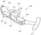
본 발명의 제1 실시예에 따른 작업 타워(100)(working tower)는, 도 2 내지 도 4에 도시된 바와 같이, 교정 스크류(10)(correction screw)를 파지하며 다른 외부 기기들[예를 들어, 로드 인서터(도 7의 300 또는 도 20의 500), 로드 리듀서(도 27의 700) 또는 인장압축기(도 31의 900)]의 작업대 역할을 하는 작업 타워로, 외관(110)(exterior pipe)과, 내관(120)(interior pipe)과, 구동 슬리브(130)(driving sleeve)와, 그리고 스크류 홀더(140)(screw holder)를 포함한다.A working
외관(110)은 작업 타워(100)의 외측을 이루는 관형상의 부재이다. 구체적으로, 외관(110)의 하반부(lower half)는 제1 및 제2 외관 분지부(110a)(110b)로 나뉘어져 분지된 형상을 하고, 제1 및 제2 외관 분지부(110a)(110b) 사이에는 제1 로드 안내홈(111)이 형성될 수 있다.The
내관(120)은 외관(110)의 내부에 그 길이 방향으로 슬라이딩 가능하게 구비된다. 구체적으로, 내관(120)의 하반부(lower half)는 제1 및 제2 내관 분지부(120a)(120b)로 나뉘어져 분지된 형상을 하고, 제1 및 제2 내관 분지부(120a)(120b) 사이에는 상술한 제1 로드 안내홈(111)에 상응하도록 제2 로드 안내홈(121)이 형성될 수 있다. 따라서, 상술한 제1 로드 안내홈(111)과 제2 로드 안내홈(121)을 통해 로드(20)가 원활하게 교정 스크류(10)의 로드 수납부(11)로 이동될 수 있다. 참고로, 로드(20)는 후술할 로드 인서터(도 7의 300)에 파지된 상태에서 제1 및 제2 로드 안내홈(111)(121)에 삽입될 수 있다.The
또한, 제1 외부 기기[일예로, 후술할 로드 리듀서(도 27의 700)]와의 나사 체결을 위해, 내관(120)의 외주연에는 외부 기기 체결용 암나사(123)(이하, "제1 암나사"라 함)가 형성될 수 있다. 예를 들어, 로드 리듀서(도 27의 700)의 체결 슬리브(도 27의 730)의 내주면과 내관(120)의 외주연은 제1 암나사(123)를 통해 서로 나사 체결될 수 있다. 또한, 제1 암나사는 후술할 슬리브 체결용 암나사(122) 보다 상부(도 2를 기준으로 상부)에 형성되므로, 로드 리듀서(도 27의 700)의 체결 슬리브(도 27의 730)의 체결시 로드 리듀서(도 27의 700)가 슬리브 체결용 암나사(122)에 간섭되지 않고 원활하게 제1 암나사(123)에 체결될 수 있다.An external device fastening female thread 123 (hereinafter, referred to as "first female thread ") is provided on the outer circumference of the
구동 슬리브(130)는 내관(120)을 그 길이 방향을 따라 상하(도 2를 기준으로 상하) 이동시키기 위해 회전되는 부재로, 외관(110)에 회전 가능하게 연결되고 내관(120)에 나사 체결된다. 내관(120)과 나사 체결되기 위해, 구동 슬리브(130)의 상단 내주면에는 수나사(131)가 형성될 수 있고, 그리고 수나사(131)와 상응하도록 내관(120)의 외주면에는 슬리브 체결용 암나사(122)(이하, "제2 암나사"라 함)가 형성될 수 있다. 따라서, 수나사(131)와 제2 암나사(122)가 나사 체결된 상태에서 구동 슬리브(130)를 정 방향 또는 역 방향으로 회전시키면 내관(120)이 상 방향 또는 하 방향으로 이동된다.The driving
또한, 제2 암나사(122)는 제1 암나사(123)와 설정 거리 이격되어 구비될 수 있다. 즉, 제2 암나사(122)와 제1 암나사(123) 사이에는 나사산이 형성되지 않은 민나사 구간(124)(threadless section)이 형성된다. 여기서, 민나사 구간(124)을 형성시키는 이유는 구동 슬리브(130)를 회전시키지 않고도 내관(120)을 당기거나 누르는 방식에 의해 스크류 홀더(140)가 인입출되도록 하기 위함이다. 결과적으로, 회전하는데 소요되는 시간을 당기거나 누르는 방식을 통해 현저히 줄일 수 있어 수술 시간을 단축시킬 수 있다. 내관(120)을 당기거나 누르는 방식에 대한 보다 구체적인 설명은 후술할 사용 상태에 대한 설명에서 하기로 한다.The second
스크류 홀더(140)는 내관(120)의 하단부에 구비되며 외관(110)으로부터 인출되면 교정 스크류(10)의 헤드부(12)를 수용할 수 있도록 자체 탄성에 의해 벌어지고 외관(110)으로 인입되면 헤드부(12)를 조일 수 있도록 수축된다. 일예로, 스크류 홀더(140)는 제1 및 제2 내관 분지부(120a)(120b)의 단부에 각각 구비되는 제1 및 제2 홀딩 암(140a)(140b)을 포함할 수 있다. 더욱이, 제1 및 제2 홀딩 암(140a)(140b)에는 교정 스크류(10)의 헤드부(12)와 체결되기 위한 체결구(141)가 형성될 수 있다. 일예로, 교정 스크류(10)의 헤드부(12)에 체결홈(13)이 형성될 경우 체결구(141)는 체결 돌기일 수 있다. 이와 반대로, 도시되지는 않았지만, 교정 스크류(10)의 헤드부(12)에 체결 돌기(미도시)가 형성된 경우라면, 제1 및 제2 홀딩 암(140a)(140b)에는 이에 상응하도록 체결홈(미도시)이 형성될 수 있다.The
또한, 제1 및 제2 홀딩 암(140a)(140b)이 외관(110)으로부터 인출되어 자체 탄성에 의해 벌어질 경우 그 사이의 거리는 교정 스크류(10)의 헤드부(12)의 외경 보다 크게 설정될 수 있다. 따라서, 본 발명의 제1 실시예에 따른 작업 타워(100)가 척추용 최소 침습 수술에 사용될 경우, 별도의 억지 끼움 없이도 교정 스크류(10)가 제1 및 제2 홀딩 암(140a)(140b)에 쉽게 삽입되므로 시술자의 수술 시간을 단축시킬 수 있다.When the first and second holding
나아가, 도 2 및 도 3에 도시된 바와 같이, 외관(110)의 외주면에는 제2 외부 기기[일예로, 후술할 인장 압축기(도 31의 700)의 타워 가압 유닛(도 31의 920)]의 고정 돌기(도 31의 922 참조)가 삽입될 수 있는 외부 기기 삽입홈(113)이 형성될 수 있다.2 and 3, a second external device (for example, a
더 나아가, 도 5와 도 6에 도시된 바와 같이, 내관(120)과 외관(110)은 관 안내부(150)에 의해 서로 좌우 회전됨 없이 상하 슬라이딩될 수 있다. 일예로, 관 안내부(150)는 제1 및 제2 외관 분지부(110a)(110b)의 내면에 각각 형성되어 제1 및 제2 내관 분지부(120a)(120b)를 안내하는 내관 안내홈(151)일 수 있다.5 and 6, the
또한, 도 5와 도 6에 도시된 바와 같이, 제1 및 제2 외관 분지부(110a)(110b)의 단부 내면에 각각 제1 및 제2 홀딩 암(140a)(140b)을 안착시킬 수 있는 홀딩암 안착홈(161)이 형성되고, 그리고 홀딩암 안착홈(161)은 내관 안내홈(151)과 연결될 수 있다.5 and 6, the first and second holding
이하, 도 3과 도 4를 다시 참조하여, 본 발명의 제1 실시예에 따른 작업 타워(100)의 사용 상태를 상세히 설명한다.3 and 4, the use state of the
먼저, 구동 슬리브(130)의 수나사(131)가 제1 암나사(123)와 제2 암나사(122) 사이의 민나사 구간(124)에 위치되면, 사용자(또는 보조 장치)가 내관(120)을 당기거나 누르는 방식에 의해 스크류 홀더(140)를 외관(110)으로부터 인입출시킬 수 있는 상태가 된다. 참고로, 본 발명의 제1 실시예에 따른 작업 타워(100)가 척추용 최소 침습 수술에 사용될 경우, 상기 사용자는 시술자일 수 있다.First, when the
이 상태에서, 도 3에 도시된 바와 같이, 사용자(또는 보조 장치)가 내관(120)을 누르게 되면, 내관(120)이 하 방향으로 이동되면서 내관(120)의 제2 암나사(122)가 구동 슬리브(130)의 하단에 걸리게 된다. 이 때, 스크류 홀더(140)는 외관(110)으로부터의 인출이 완료된다.3, when the user (or auxiliary device) presses the
또한, 도 4에 도시된 바와 같이, 사용자(또는 보조 장치)가 내관(120)을 당기게 되면, 내관(120)이 상 방향으로 이동되면서 내관(120)의 제2 암나사(122)가 구동 슬리브(130)의 수나사(131)에 걸리게 된다. 이 후, 사용자(또는 보조 장치)가 구동 슬리브(130)를 돌려 구동 슬리브(130)의 수나사(131)가 내관(120)의 제2 암나사(122)에 체결시키면, 스크류 홀더(140)는 외관(110)으로부터 인입이 완료된다.4, when the user (or auxiliary device) pulls the
이하, 도 7 내지 도 12를 참조하여, 본 발명의 제2 실시예에 따른 로드 인서터를 상세히 설명한다.Hereinafter, a rod inserter according to a second embodiment of the present invention will be described in detail with reference to FIGS. 7 to 12. FIG.
도 7은 본 발명의 제2 실시예에 따른 로드 인서터를 나타낸 사시도이고, 도 8은 도 7의 로드 인서터의 정면도이며, 그리고 도 9는 도 8의 로드 인서터를 IX-IX 선으로 잘라서 본 단면도이다.FIG. 7 is a perspective view of a rod inserter according to a second embodiment of the present invention, FIG. 8 is a front view of the rod inserter of FIG. 7, and FIG. 9 is a cross- Fig.
도 10은 도 8의 "A"부의 평면도이고, 도 11은 도 8의 로드 인서터를 XI-XI 선으로 잘라서 본 단면도이며, 그리고 도 12는 도 8의 로드 인서터를 XII-XII 선으로 잘라서 본 단면도이다.Fig. 10 is a plan view of the "A" part of Fig. 8, Fig. 11 is a sectional view taken along the line XI-XI in Fig. 8 and Fig. 12 is a cross- Fig.
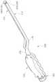
본 발명의 제2 실시예에 따른 로드 인서터(300)(rod inserter)는, 로드(20)(rod)를 파지하여 로드(20)를 적어도 두 개의 교정 스크류(10)의 로드 수납부(11)(rod accommodating part)에 안착시키는 로드 인서터로, 도 7 내지 도 12에 도시된 바와 같이, 고정 바(310)(fixed bar)와, 이동 바(320)(moving bar)와, 조절 노브(330)(adjusting knob)와, 그리고 로드 홀더(340)(rod holder)를 포함한다.The
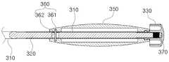
고정 바(310)는 이동 바(320)에 대해 상대적으로 고정되게 구비된 바 형상의 고정 부재로서, 이동 바(320)를 그 길이 방향으로 슬라이딩 가능하게 지지한다. 또한, 고정 바(310)의 외면에는 사용자가 용이하게 로드 인서터(300)를 잡을 수 있도록 고정 핸들(350)(fixed handle)이 구비될 수 있다. 이하, 고정 바(310)의 일단은 도 7을 기준으로 고정 바(310)의 좌측단을 가리키고, 고정 바(310)의 타단은 도 7을 기준으로 고정 바(310)의 우측단을 가리킨다.The fixing
이동 바(320)는 고정 바(310)에 대해 상대적으로 이동 가능하게 구비된 바 형상의 이동 부재로서, 고정 바(310)에 그 길이 방향을 따라 슬라이딩 가능하게 구비된다. 이하, 이동 바(320)의 일단은 도 7을 기준으로 이동 바(320)의 좌측단을 가리키고, 이동 바(320)의 타단은 도 7을 기준으로 이동 바의 우측단을 가리킨다.The
조절 노브(330)는 회전을 통해 이동 바(320)의 이동 거리를 조절하는 것으로, 고정 바(310)에 회전가능하게 연결되고 이동 바(320)에 나사 체결된다. 나아가, 이동 바(320)가 조절 노브(330) 측으로 충분히 진행할 수 있도록 조절 노브(330)와 이동 바(320)의 타단 사이에는 빈 공간의 이동용 유격부(370)가 형성될 수 있다. 따라서, 이동 바(320)가 이동용 유격부(370)를 통해 충분히 조절 노브(330) 측으로 이동될 수 있으므로 로드 홀더(340)의 파지력을 증가시킬 수 있다.The
로드 홀더(340)는, 도 7 및 도 8에 도시된 바와 같이, 고정 바(310)의 일단과 이동 바(320)의 일단과의 사이에 구비되며 이동 바(320)의 이동에 따라 로드(20)를 파지한다. 일예로, 로드 홀더(340)는 이동 바(320)의 일단에 구비되는 후크(341)와, 그리고 고정 바(310)의 일단에 구비되는 로드 지지부(342)를 포함할 수 있다. 또한, 로드 지지부(342)는 후크(341)가 조절 노브(330) 측으로 이동될 경우 후크(341)와 함께 로드(20)의 중심부를 파지하는 원호 형상의 접촉면(342a)을 가질 수 있다. 로드 홀더(340)가 로드(20)의 중심부를 파지하는 과정은 후술할 사용 상태에 대한 설명에서 하기로 한다.7 and 8, the
이와 더불어, 로드 홀더(340)는, 도 10에 도시된 바와 같이, 로드 지지부(342)의 단부에 형성되는 제1 홀딩 홈(343)과, 그리고 후크(341)의 단부에 형성되며 제1 홀딩 홈(343)과 함께 로드(20)의 단부를 파지하는 제2 홀딩 홈(344)을 더 포함할 수 있다. 로드 홀더(340)가 로드(20)의 단부를 파지하는 과정은 후술할 사용 상태에 대한 설명에서 하기로 한다.10, the
한편, 사용자가 로드(20)를 작업 타워(도 4의 100)의 로드 안내홈(도 4의 111)과 교정 스크류(10)의 로드 수납부(11)에 순차적으로 삽입하는 동안 작업 타워(도 4의 100)와의 간섭을 미연에 막고 수술 부위에 대한 시야를 확보할 수 있도록 이동 바(320)와 고정 바(310)는 제1 및 제2 절곡부(B1)(B2)에 의해 절곡된 형상을 할 수 있다.Meanwhile, while the user sequentially inserts the
이 경우, 이동 바(320)가 그 길이 방향으로 원활하게 이동되도록, 고정 핸들(350)과 로드 홀더(340)는 서로 평행하게 놓인 직선 상에 각각 위치될 수 있다. 이하, 도 8, 도 11 및 도 12를 참조하여, 제1 및 제2 절곡부(B1)(B2)를 갖는 상태에서 이동 바(320)가 고정 바(310)에 대해 슬라이딩되는 구조를 설명한다.In this case, the fixing
도 8 및 도 11에 도시된 바와 같이, 로드 홀더(340)에서 제1 절곡부(B1)까지는 이동 바(320)와 고정 바(310)가 레일 구조(도 11 참조)에 의해 서로 슬라이딩 가능하게 결합될 수 있다. 도 8 및 도 12에 도시된 바와 같이, 제2 절곡부(B2)에서 조절 노브(330)까지는 이동 바(320)가 고정 바(310)에 슬라이딩 가능하게 삽입되는 삽입 구조(도 12 참조)를 가질 수 있다. 도 8에 도시된 바와 같이, 제1 절곡부(B1)와 제2 절곡부(B2) 사이에는 이동 바(320)와 고정 바(310)가 서로 떨어져 위치되는 이격 구조를 가질 수 있다. 이러한 레일 구조(도 11 참조), 삽입 구조(도 12 참조) 및 이격 구조를 통해, 이동 바(320)는 고정 바(310)에 대해 그 길이 방향을 따라 슬라이딩 가능하게 구비될 수 있다.As shown in FIGS. 8 and 11, the
또한, 도 9에 도시된 바와 같이, 이동 바(320)의 이동 거리를 제한하기 위해 이동 바(320)는 제1 이동 제한 유닛(360)을 통해 고정 바(310)에 연결될 수 있다. 일예로, 제1 이동 제한 유닛(360)은 스톱 핀(361)과, 그리고 이동 제한 홈(362)을 포함할 수 있다. 스톱 핀(361)은 고정 바(310)에 가로질러 구비된다. 이동 제한 홈(362)은 이동 바(320)에 형성되고 스톱 핀(361)이 삽입되며 이동 바(320)의 이동에 따라 스톱 핀(361)에 걸리는 일단과 타단을 갖는 긴 홈이다.9, the
이하, 도 13a 내지 도 16을 참조하여, 본 발명의 제2 실시예에 따른 로드 인서터의 사용 상태를 상세히 설명한다.Hereinafter, the use state of the rod inserter according to the second embodiment of the present invention will be described in detail with reference to FIGS. 13A to 16. FIG.
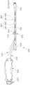
도 13a 및 도 13b는 도 7의 로드 인서터(300)가 로드(20)의 중심부를 파지하기 전 및 후 상태를 나타낸 도면이고, 그리고 도 14는 도 7의 로드 인서터(300)가 로드(20)의 중심부를 파지한 상태에서 작업 타워(도 4의 100)의 로드 안내홈(도 4의 111)에 로드(20)를 삽입한 상태를 나타낸 개략적 사시도이다.13A and 13B are views showing the state before and after the
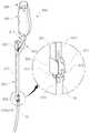
도 15a 및 도 15b는 도 7의 로드 인서터(300)가 로드(20)의 단부를 파지하기 전 및 후 상태를 나타낸 도면이고, 그리고 도 16은 도 7의 로드 인서터(300)가 로드(20)의 단부를 파지한 상태에서 작업 타워(도 4의 100)의 로드 안내홈(도 4의 111)에 로드(20)를 삽입한 상태를 나타낸 개략적 사시도이다.15A and 15B are views showing the state before and after the
로드(20)의 중심부를 파지하는 예로서, 도 13a에 도시된 바와 같이 로드(20)의 중심부를 로드 홀더(340)에 가로 질러 위치시킨 후, 사용자가 조절 노브(330)를 정 방향으로 회전시켜 이동 바(320)를 최대한 조절 노브(330) 측으로 이동시키면, 도 13b에 도시된 바와 같이 로드(20)의 중심부는 후크(341)와 로드 지지부(342)에 의해 파지된다. 참고로, 본 발명의 제2 실시예에 따른 로드 인서터(300)가 척추용 최소 침습 수술에 사용될 경우, 상기 사용자는 시술자일 수 있다.As an example of grasping the center portion of the
이렇게 파지된 상태에서, 도 14에 도시된 바와 같이, 로드 인서터(300)를 제1 및 제2 작업 타워(100a)(100b)의 사이에 위치시킨 상태에서, 로드 인서터(300)로 로드(20)의 일단부를 먼저 제1 작업 타워(100a)의 로드 안내홈(111)에 삽입시킨 후, 로드 인서터(300)를 틀면서 로드(20)의 타단부를 제2 작업 타워(100b)의 로드 안내홈(111)에 삽입시킨다. 그리고 나서, 로드 인서터(300)로 로드(20)를 하강시켜 제1 및 제2 교정 스크류(10a)(10b)의 로드 수납부(11)에 로드(20)의 양단부를 각각 안착시킨다. 끝으로, 후술할 로드 인듀서(도 27의 700)를 통한 작업까지 완료되면 조절 노브(330)를 역 방향으로 회전시켜 로드(20)의 파지를 해제한다.14, in a state where the
한편, 로드(20)의 단부를 파지하는 예로서, 도 15a에 도시된 바와 같이 로드(20)의 단부를 로드 홀더(340)의 정방을 향해 위치시킨 후, 사용자가 조절 노브(330)를 정 방향으로 회전시켜 이동 바(320)를 최대한 조절 노브(330) 측으로 이동시키면, 도 15b에 도시된 바와 같이 로드(20)의 단부는 제1 및 제2 홀딩 홈(343)(344)에 의해 파지된다.15A, after the end of the
이렇게 파지된 상태에서, 도 16에 도시된 바와 같이, 로드 인서터(300)를 제1 작업 타워(100a) 중 제2 작업 타워(100b)를 향하는 방향의 반대 방향에 위치시킨 상태에서, 로드 인서터(300)로 로드(20)의 일단부를 제1 작업 타워(100a)의 로드 안내홈(111)과 제2 작업 타워(100b)의 로드 안내홈(111)에 순차적으로 삽입시킨다. 그리고 나서, 로드 인서터(300)로 로드(20)를 하강시켜 제1 및 제2 교정 스크류(10a)(10b)의 로드 수납부(11)에 로드(20)의 양단부를 각각 안착시킨다. 끝으로, 후술할 로드 인듀서(도 27의 700)를 통한 작업까지 완료되면 조절 노브(330)를 역 방향으로 회전시켜 로드(20)의 파지를 해제한다.16, in a state in which the
이하, 도 17 내지 도 21을 참조하여, 본 발명의 제2 실시예의 변형례에 따른 로드 인서터를 상세히 설명한다.Hereinafter, a rod inserter according to a modification of the second embodiment of the present invention will be described in detail with reference to Figs. 17 to 21. Fig.
도 17은 본 발명의 제2 실시예의 변형례에 따른 로드 인서터를 나타낸 정면도이고, 도 18은 도 17의 로드 인서터의 로드 홀더를 나타낸 사시도이며, 그리고 도 19는 도 17의 로드 인서터에 커버가 장착된 상태를 나타낸 사시도이다.17 is a front view showing a rod inserter according to a modification of the second embodiment of the present invention, Fig. 18 is a perspective view showing the rod holder of the rod inserter of Fig. 17, and Fig. 19 is a perspective view showing the rod inserter of Fig. Fig. 6 is a perspective view showing a state in which the cover is mounted.
도 20은 도 19의 로드 인서터의 정면도이고, 그리고 도 21은 도 20의 로드 인서터의 요부를 절개하여 나타낸 도면이다.FIG. 20 is a front view of the rod inserter of FIG. 19, and FIG. 21 is a cutaway view of the recess of the rod inserter of FIG.
본 발명의 제2 실시예의 변형례에 따른 로드 인서터(500)(rod inserter)는, 도 17 내지 도 21에 도시되 바와 같이, 로드 홀더(510)의 구성이 변한 것과, 커버(520)가 더 추가되는 특징을 갖는 것과, 그리고 제1 다단 조절 유닛(530) 및 제2 이동 제한 유닛(540)이 더 추가되는 특징을 갖는 것을 제외하고는 상술한 본 발명의 제2 실시예와 동일하므로, 이하에서는 로드 홀더(510), 커버(520), 제1 다단 조절 유닛(530) 및 제2 이동 제한 유닛(540)에 대해서만 설명한다. 또한, 본 발명의 제2 실시예와 동일한 구성요소에는 동일한 도면 부호를 부여한다.A
로드 홀더(510)는, 도 17 및 도 18에 도시된 바와 같이, 너클(511)(knuckle)과, 로드 홀더 브라켓(512)(rod holder bracket)과, 그리고 클립(513)(clip)을 포함한다.The
너클(511)은 회전 자유도를 높이기 위해 부재간 회동 가능하게 연결되는 것으로, 너클(511)의 일단은 이동 바(320)의 일단에 회전가능하게 구비되고, 너클(511)의 타단은 로드 홀더 브라켓(512)의 일단에 회동 가능하게 구비된다. 여기서, 너클(511)의 일단은 도 17을 기준으로 너클(511)의 우측단을 가리키고, 너클(511)의 타단은 도 17을 기준으로 너클(511)의 좌측단을 가리킨다.One end of the
로드 홀더 브라켓(512)은 클립(513)을 고정하는 것으로 절곡된 형상을 가지며, 로드 홀더 브라켓(512)의 일단은 너클(511)의 타단에 회동 가능하게 구비되고, 로드 홀더 브라켓(512)의 타단은 고정 바(310)의 일단에 회동 가능하게 구비된다. 여기서, 로드 홀더 브라켓(512)의 일단은 도 17을 기준으로 로드 홀더 브라켓(512)의 우측단을 가리키고, 로드 홀더 브라켓(512)의 타단은 도 17을 기준으로 로드 홀더 브라켓(512)의 좌측단을 가리키며, 그리고 상술한 절곡된 형상은 도 17을 기준으로 로드 홀더(510)의 타단이 대략 위로 절곡되어 이루어진 형상이다.The
클립(513)은 로드 홀더 브라켓(512)에 고정되며 로드(20)의 단부를 파지한다. 특히, 도 18에 도시된 바와 같이, 클립(513)은 원호 형상을 할 수 있으며, 로드(20)의 단부가 원활하게 클립(513)에 끼워지도록 클립(513)의 양단부는 자체 탄성에 의해 설정 간격 벌어진 상태로 위치될 수 있다. 또한, 클립(513)의 내면에는 로드(20)의 단부를 파지하기 위한 체결구(513a)가 형성될 수 있다. 일예로, 로드(20)의 단부에 체결홈(도 22의 20a)이 형성될 경우에는 체결구(513a)는 체결 돌기일 수 있다. 다른 예로, 도시되지는 않았지만, 로드(20)의 단부에 체결 돌기(미도시)가 형성될 경우에는 클립(513)의 내면에 체결홈(미도시)이 형성될 수 있다.The
로드 홀더(510)가 이러한 구성 요소를 가짐에 따라, 이동 바(320)가 너클(511) 측으로 이동하게 되면, 너클(511)에 의해 로드 홀더 브라켓(512) 및 클립(513)이 고정 바(310)의 일단을 기준으로 회전하면서 클립(513)에 파지된 로드(20)가 함께 회전될 수 있다. 이에 대한 보다 구체적인 설명은 후술할 사용 상태에 대한 설명에서 하기로 한다.As the
나아가, 도 19 내지 도 21에 도시된 바와 같이, 이동 바(320)의 외면에는 그 길이 방향으로 슬라이딩 가능하게 커버(520)가 구비될 수 있다. 특히, 커버(520)는 고정 바(310)를 감싸는 커버 바디(521)와, 그리고 커버 바디(521)의 일단에 구비되며 커버(520)가 클립(513)을 향하는 방향으로 이동시 클립(513)을 감싸 클립(513)이 벌어지는 것을 막는 클립 잠금부(522)를 포함할 수 있다. 따라서, 클립(513)은 커버(520)의 클립 잠금부(522)에 의해 완벽하게 파지되므로 클립(513)이 벌어져 클립(513)에 파지된 로드(20)가 빠지는 현상을 미연에 차단할 수 있다.Further, as shown in FIGS. 19 to 21, the
또한, 클립 잠금부(522)에 의해 클립(513)이 잠긴 후 이동 바(320)가 클립(513) 측으로 이동할 경우 로드(20)가 클립 잠금부(522)에 의해 방해됨 없이 원활하게 회전되도록, 클립 잠금부(522)에는 로드 통과홈(522a)이 형성될 수 있다.When the
또한, 사용자가 커버(520)를 용이하게 밀거나 당길 수 있도록, 커버(520)는 커버 바디(521)의 타단에 구비되며 커버(520)를 밀거나 당기는 커버 손잡이(523)를 더 포함할 수 있다.The
더 나아가, 도 21에 도시된 바와 같이, 커버(520)가 슬라이딩될 때 사용자에게 동작감을 부여하기 위해, 커버(520)는 제1 다단 조절 유닛(530)을 통해 고정 바(310)와 연결될 수 있다. 일예로, 제1 다단 조절 유닛(530)은 고정 바(310)에 탄성 지지되는 제1 볼(531)과, 그리고 제1 볼(531)이 다단으로 걸리도록 커버 바디(521)에 형성되는 복수개의 제1 걸림홈(532)을 포함할 수 있다. 따라서, 제1 볼(531)이 제1 걸림홈(532)에 위치되거나 빠질 때 "똑딱"하는 소리가 나면서 사용자에게 그 소리를 제공하기 때문에 동작감이 극대화될 수 있다.21, the
더 나아가, 도 20 및 도 21에 도시된 바와 같이, 커버(520)의 이동 거리를 제한하기 위해, 커버(520)는 제2 이동 제한 유닛(540)을 통해 고정 바(310)와 연결될 수 있다. 일예로, 제2 이동 제한 유닛(540)은 커버(520)에 그 길이 방향을 따라 형성되는 적어도 하나의 장공(541)과, 그리고 적어도 하나의 장공(541)에서 각각 이동되도록 고정 바(310)에 구비되는 적어도 하나의 스톱 돌기(542)를 포함할 수 있다.20 and 21, the
이하, 도 22 내지 도 25를 참조하여, 본 발명의 제2 실시예의 변형례에 따른 로드 인서터(500)의 사용 상태를 상세히 설명한다.Hereinafter, the use state of the
도 22는 도 19의 로드 인서터(500)에 로드(20)가 장착되고 있는 상태를 나타낸 사시도이고, 그리고 도 23은 도 19의 로드 인서터(500)에 로드(20)가 장착된 상태를 나타낸 사시도이다.22 is a perspective view showing a state in which the
도 24는 도 23의 상태에서 로드 인서터(500)의 커버(520)가 클립(513) 측으로 이동되어 클립(513)이 잠긴 상태를 나타낸 사시도이고, 그리고 도 25는 도 24의 상태에서 조절 노브(330)의 회전으로 이동 바(320)가 클립(513) 측으로 이동되면서 로드(20)가 회전되는 상태를 나타낸 사시도이다.24 is a perspective view showing a state in which the
먼저, 도 22에 도시된 바와 같이, 사용자가 커버(520)의 클립 잠금부(522)를 도면상 상 방향으로 이동시켜 로드 홀더(510)의 클립(513)을 외부에 노출시키면, 클립(513)은 자체 탄성에 의해 화살표(1) 방향으로 설정 간격 벌어지게 된다. 이 후, 사용자가 로드(20)의 단부를 클립(513)에 화살표(2) 방향으로 넣으며, 도 23에 도시된 바와 같이, 클립(513)에 로드(20)의 단부가 위치된다. 이 때, 클립(513)의 체결 돌기(513a)가 로드(20)의 단부의 체결홈(20a)에 느슨하게 체결된다. 참고로, 본 발명의 제2 실시예의 변형례에 따른 로드 인서터(500)가 척추용 최소 침습 수술에 사용될 경우, 상기 사용자는 시술자일 수 있다.22, when the user moves the
그리고 나서, 도 24에 도시된 바와 같이, 사용자가 커버(520)의 클립 잠금부(522)를 도면상 하 방향으로 이동시키면, 클립 잠금부(522)에 의해 클립(513)이 조여지면서 로드(20)의 단부가 클립(513)에 완벽하게 장착된다.24, when the user moves the
이 후, 도 17, 도 18 및 도 25에 도시된 바와 같이, 사용자가 조절 노브(330)를 화살표 방향으로 돌리면 이동 바(320)가 도면상 하 방향으로 이동하면서 너클(511)을 밀게 되고, 밀린 너클(511)에 의해 로드 홀더 브라켓(512) 및 클립(513)이 고정 바(310)의 일단을 기준으로 회전되면서 클립(513)에 파지된 로드(20)가 함께 회전되면서 로드(20)는 이동 바(320)에 대해 절곡된 상태가 된다.17, 18, and 25, when the user rotates the
참고로, 사용자는 도 24의 상태인 로드(20)가 이동 바(320)에 대해 절곡되지 않은 상태에서 로드 인서터(500)를 제1 작업 타워(도 16의 100a 참조) 중 제2 작업 타워(도 16의 100b 참조)를 향하는 방향의 반대 방향에 위치시킨다(도 16 참조). 이 후, 도 25의 상태로 로드(20)가 절곡되면 로드(20)가 제1 작업 타워(도 16의 100a 참조)의 로드 안내홈(도 16의 111 참조)과 제2 작업 타워(도 16의 100b 참조)의 로드 안내홈(도 16의 111 참조)에 순차적으로 삽입된다. 그리고 나서, 사용자가 로드 인서터(500)로 로드(20)를 하강시켜 제1 및 제2 교정 스크류(10a)(10b)의 로드 수납부(11)에 로드(20)의 양단부를 각각 안착시킨다. 끝으로, 후술할 로드 인듀서(500)를 통한 작업까지 완료되면 사용자는 클립 잠금부(522)를 도면상 상 방향으로 이동시켜 로드(20)의 파지를 해제시킨다. 여기서, 클립 잠금부(522)가 상 방향으로 이동되면, 클립(513)이 자체 탄성에 의해 벌어지면서 로드(20)의 파지는 해제된다.The user can move the
이하, 도 26 및 도 27을 참조하여, 본 발명의 제3 실시예에 따른 로드 리듀서를 상세히 설명한다.Hereinafter, the load reducer according to the third embodiment of the present invention will be described in detail with reference to FIGS. 26 and 27. FIG.
도 26은 본 발명의 제3 실시예에 따른 로드 리듀서를 나타낸 사시도이고, 그리고 도 27은 도 26의 로드 리듀서의 종단면도이다.FIG. 26 is a perspective view of a load reducer according to a third embodiment of the present invention, and FIG. 27 is a longitudinal sectional view of the rod reducer of FIG. 26.
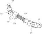
본 발명의 제3 실시예에 따른 로드 리듀서(700)(rod reducer)는, 교정 스크류(도 28의 10)의 로드 수납부(도 28의 11)에 안착된 로드(도 28의 20)를 아래로 누르면서 로드 수납부(도 29의 11)에 셋 스크류(도 29의 S)를 체결하는 로드 리듀서로, 도 26 및 도 27에 도시된 바와 같이, 외측 부재(710)(exterior member)와, 내측 부재(720)(interior member)와, 체결 슬리브(730)(coupling sleeve)와, 그리고 회전 핸들(740)(rotation handle)을 포함한다.The rod reducer according to the third embodiment of the present invention is a rod reducer according to the third embodiment of the present invention in which the rod (20 in Fig. 28) that is seated in the rod accommodating portion (11 in Fig. 28) 29, the rod reducer for tightening the set screw (S in Fig. 29) to the rod receiving portion (11 in Fig. 29) An
외측 부재(710)는 관 형상을 하고, 그 하단부에는 셋 스크류(도 28의 S)를 장착시킬 수 있는 셋 스크류 장착부(711)가 형성된다.The
내측 부재(720)는 봉 형상을 하고, 외측 부재(710)의 내부에 슬라이딩 가능하게 구비되며, 그리고 로드(도 28의 20)에 접하도록 그 하단에는 외측 부재로부터 인출된 상태의 하단 인출부(721)를 갖는다.The
체결 슬리브(730)는 교정 스크류(10)를 파지한 제3 외부 기기(OS)[일예로, 작업 타워(도 4의 100)]에 체결되는 동안 내측 부재(720)를 하강시켜 로드(도 28의 20)가 내측 부재(720)의 하단 인출부(721)에 의해 눌리도록 하는 것이다. 여기서, 제3 외부 기기(OS)가 작업 타워(100)와 같이 관 형상을 할 경우, 외측 부재(710)는 제3 외부 기기(OS)의 내부에 삽입되는 구조를 가질 수 있다(도 28 참조).The
회전 핸들(740)은 셋 스크류(도 29의 S)가 교정 스크류(도 29의 10)의 로드 수납부(도 29의 11)에 나사 체결되도록 외측 부재(710)를 회전시키는 것으로, 외측 부재(710)의 상단부에 고정될 수 있다.The
나아가, 체결 슬리브(730)의 내주면은 제3 외부 기기(도 28의 OS)의 외주면에 나사 체결되는 구조를 가질 수 있다. 즉, 도 27에 도시된 바와 같이, 체결 슬리브(730)의 내주면에는 외부 기기용 수나사(732)(이하, "제2 수나사"라 함)가 형성될 수 있다. 예를 들어, 제3 외부 기기(OS)가 작업 타워(도 4의 100)일 경우, 제2 수나사(732)는 작업 타워(100)의 제1 암나사(도 4의 123)에 나사 체결될 수 있다.Furthermore, the inner circumferential surface of the
또한, 도 27에 도시된 바와 같이, 체결 슬리브(730)는 연결 유닛(750)에 의해 외측 부재(710) 및 내측 부재(720)에 연결될 수 있다. 일예로, 연결 유닛(750)은 내측 부재(720)에 관통되는 관통홀(751)과, 관통홀(751)에 삽입되는 연결핀(752)과, 연결핀(752)의 양단이 삽입되도록 외측 부재(710)에 형성되되 외측 부재(710)가 하방으로 이동할 수 있도록 길게 형성된 슬라이딩홀(753)과, 체결 슬리브(730)의 내주면에 원주 방향을 따라 형성되는 장착홈(754)과, 그리고 장착홈(754)에 회전 가능하게 장착되며 연결핀(752)의 양단부를 삽입하는 제1 및 제2 삽입홀(755a)(755b)이 각각 형성되는 회전링(755)을 포함할 수 있다.27, the
또한, 셋 스크류(S)가 교정 스크류(10)의 로드 수납부(11)에 체결되는 동안, 내측 부재(720)의 하단 인출부(721)가 외측 부재(710)의 내부로 완전히 인입될 수 있도록, 외측 부재(710)의 길이 방향을 기준으로 슬라이딩홀(753)의 길이는 내측 부재(720)의 하단 인출부(721)의 길이 보다 길게 설정될 수 있다.While the set screw S is fastened to the
또한, 셋 스크류(도 29의 S)가 교정 스크류(도 29의 10)의 로드 수납부(도 29의 11)에 체결되기 전에는 내측 부재(720)의 하단 인출부(721)가 외측 부재(710)로부터 인출된 상태로 유지되도록, 내측 부재(720)는 외측 부재(710)에 탄성 지지될 수 있다. 일예로, 내측 부재(720) 및 외측 부재(710)는 각각 체결 슬리브(730) 및 회전 핸들(740)을 통해서 서로 탄성 지지될 수 있으며, 그리고 탄성 지지를 위해 체결 슬리브(730)와 회전 핸들(740) 사이에 탄성체(756)가 구비될 수 있다.Before the set screw (S in Fig. 29) is fastened to the rod receiving portion (11 in Fig. 29) of the calibration screw (10 in Fig. 29), the lower
이하, 도 28 및 도 29를 참조하여, 본 발명의 제3 실시예에 따른 로드 리듀서(700)의 사용 상태를 상세히 설명한다.Hereinafter, the use state of the
도 28은 체결 슬리브(730)가 회전되는 동안 내측 부재(720)의 하단 인출부(721)에 의해 로드(20)가 눌려지고 있는 상태를 나타낸 개략적 단면도이다.28 is a schematic sectional view showing a state in which the
도 29는 회전 핸들(740)이 눌리면서 회전되는 동안 셋 스크류(S)가 교정 스크류(10)의 로드 삽입부(11)에 체결되고 있는 상태를 나타낸 개략적 단면도이다.29 is a schematic sectional view showing a state in which the set screw S is fastened to the
먼저, 사용자는 로드 리듀서(700)를 제3 외부 기기(OS)에 삽입시킨다. 참고로, 본 발명의 제3 실시예에 따른 로드 리듀서(700)가 척추용 최소 침습 수술에 사용될 경우, 상기 사용자는 시술자일 수 있다.First, the user inserts the
그리고 나서, 도 28에 도시된 바와 같이, 사용자가 체결 슬리브(730)를 돌리면, 회전링(755)에 의해 체결 슬리브(730)가 원활하게 회전됨과 동시에 체결 슬리브(730)의 제2 수나사(732)가 제3 외부 기기(OS)[일예로, 작업 타워(도 4의 100)]의 제1 암나사(도 4의 123 참조)와 나사 체결되면서, 체결 슬리브(730)가 하방으로 이동하게 된다. 이 때, 연결핀(752)에 의해 체결 슬리브(730)와 함께 구속된 외측 부재(710) 및 내측 부재(720)가 동시에 하방으로 이동하게 된다.28, when the user rotates the
내측 부재(720)의 하단 인출부(721)에 의해 로드(20)가 교정 스크류(10)의 로드 수납부(11)의 바닥면에 접하게 되면, 도 29에 도시된 바와 같이, 사용자는 체결 슬리브(730)의 회전을 정지시키고, 회전 핸들(740)을 하방으로 누르면서 정 방향으로 돌려 셋 스크류(S)를 교정 스크류(10)의 로드 수납부(11)에 나사 체결시킨다. 이 때, 내측 부재(720)는 체결 슬리브(730)와 함께 고정된 상태에 있게 되고, 외측 부재(710)만이 슬라이딩홀(753)을 통해 하방으로 이동하게 된다. 즉, 외측 부재(710)가 하방으로 점차 이동되는 동안 내측 부재(720)는 상대적으로 외측 부재(710) 안으로 점차 들어가게 된다.When the
따라서, 로드(20)를 누르는 작업이 셋 스크류(S)의 체결과 동시에 이루어지므로, 로드(20)와 셋 스크류(S) 사이에 조직(tissue)이 낄 우려를 미연에 차단할 수 있다.Accordingly, since the pressing operation of the
이하, 도 30 내지 도 35를 참조하여, 본 발명의 제4 실시예에 따른 인장압축기를 상세히 설명한다.Hereinafter, a tension compressor according to a fourth embodiment of the present invention will be described in detail with reference to FIGS. 30 to 35. FIG.
도 30은 본 발명의 제4 실시예에 따른 인장압축기를 나타낸 사시도이고, 도 31은 도 30의 인장압축기의 평면도이며, 그리고 도 32는 도 30의 인장 압축기의 정면도이다.FIG. 30 is a perspective view of a tension compressor according to a fourth embodiment of the present invention, FIG. 31 is a plan view of the tension compressor of FIG. 30, and FIG. 32 is a front view of the tension compressor of FIG.
도 33은 도 31의 인장 압축기를 XXXIII-XXXIII 선으로 잘라서 본 단면도이고, 도 34는 도 32의 인장 압축기의 스크류 봉 등을 상세히 나타낸 사시도이며, 그리고 도 35는 도 30의 인장 압축기를 정면에서 위로 바라본 사시도이다.FIG. 33 is a cross-sectional view cut along the line XXXIII-XXXIII of FIG. 31, FIG. 34 is a perspective view showing a screw rod or the like of the tension compressor of FIG. 32 in detail, and FIG. 35 is a cross- It is a perspective view.
본 발명의 제4 실시예에 따른 인장압축기(900)(compression-distraction tool)는, 제1 및 제2 작업 타워(도 36a의 100a)(도 36a의 100b)의 각 하단에 있는 제1 및 제2 교정 스크류(도 36a의 10a)(도 36a의 10b) 사이를 벌려 인장시키거나 좁혀 압축시키는 인장압축기로, 도 30 내지 도 35에 도시된 바와 같이, 중심축(910)(pivot)과, 타워 가압 유닛(920)(tower compressing unit)과, 그리고 타워 받침대(930)(tower supporter)를 포함한다.The compression-
중심축(910)은 원기둥 형상을 하며, 제1 및 제2 작업 타워(100a)(100b) 사이에 대략 수직하게 위치된다(도 36a 및 도 36b 참조).The
타워 가압 유닛(920)은 중심축(910)의 일단에 구비되며 중심축(910)을 기준으로 제1 및 제2 작업 타워(100a)(100b)가 기울어지도록 제1 및 제2 작업 타워(100a)(100b)를 가압한다. 여기서, 중심축(910)의 일단은 도 31을 기준으로 중심축(910)의 상단을 가리킨다.The
타워 받침대(930)는 중심축(910)의 타단에 회전 가능하게 구비되어 제1 및 제2 작업 타워(100a)(100b)가 중심축(910)의 길이 방향으로 미끄러지며 이동되는 것을 막아준다. 여기서, 중심축(910)의 타단은 도 31을 기준으로 중심축(910)의 하단을 가리킨다.The
나아가, 본 발명의 제4 실시예에 따른 인장압축기(900)는 제1 및 제2 작업 타워(100a)(100b) 사이로 타워 받침대(930)가 들어갈 수 있도록 타워 받침대(930)를 회전시키는 조절 손잡이(940)를 더 포함할 수 있다. 일예로, 조절 손잡이(940)는 타워 받침대(930)에 고정되며 중심축(910)에 회전 가능하게 구비될 수 있다.The
또한, 도 33에 도시된 바와 같이, 조절 손잡이(940)가 회전될 때 사용자에게 동작감을 부여하기 위해, 조절 손잡이(940)는 제2 다단 조절 유닛(950)을 통해 중심축(910)과 연결될 수 있다. 일예로, 제2 다단 조절 유닛(950)은 중심축(910)에 탄성 지지되는 제2 볼(951)과, 그리고 제2 볼(951)이 다단으로 걸리도록 조절 손잡이(940)의 외주면에 형성되는 복수개의 제2 걸림홈(952)을 포함할 수 있다. 따라서, 제2 볼(951)이 제2 걸림홈(952)에 위치되거나 빠질 때 "똑딱"하는 소리가 나면서 사용자에게 그 소리를 제공하기 때문에 동작감이 극대화될 수 있다.33, the
또한, 타워 받침대(930)가 제1 및 제2 작업 타워(100a)(100b)에 원활하게 삽입되도록 타워 받침대(930)를 제1 및 제2 작업 타워(100a)(100b)와 대략 평행하게 놓이게 하거나, 타워 받침대(930)가 제1 및 제2 작업 타워(100a)(100b)를 받치도록 타워 받침대(930)를 제1 및 제2 작업 타워(100a)(100b)에 대략 수직하게 놓이게 하기 위해, 복수개의 제2 걸림홈(952)은 90도 간격으로 4개가 형성될 수 있다.It is also possible to place the
더 나아가, 도 32, 도 34 및 도 35에 도시된 바와 같이, 상술한 타워 가압 유닛(920)은 중심축(910)의 일단에 수직하게 구비되는 연결 브라켓(921)과, 연결 브라켓(921)에 구비되며 제1 작업 타워(100a)의 외부 기기 삽입홈(도 4의 113)에 끼워지는 고정 돌기(922)와, 중심축(910)과 이격되어 연결 브라켓(921)에 구비되는 가압 바디(923)와, 가압 바디(923)에 회전 가능하게 구비되는 스크류 봉(924)과, 스크류 봉(924)에 나사 결합되는 가압 너트(925)와, 가압 너트(925)에 구비되며 제2 작업 타워(100b)를 당길 수 있도록 제2 작업 타워(100b)의 일측에 위치되는 가압 돌기(926)와, 그리고 가압 바디(923)의 외측에 회전 가능하게 구비되며 가압 너트(925)가 이동되도록 스크류 봉(924)을 회전시키는 구동 핸들(927)(driving handle)을 포함할 수 있다. 따라서, 사용자가 구동 핸들(927)을 정 방향 또는 역 방향으로 돌리면, 스크류 봉(924)이 정 방향 또는 역 방향으로 회전되면서 가압 너트(925)는 도면상 좌측 방향 또는 우측 방향으로 이동하게 된다. 따라서, 가압 너트(925)에 구비된 가압 돌기(926) 또한 이동하면서 고정 돌기(922)와 함께 제1 및 제2 작업 타워(100a)(100b)를 강하게 파지하게 된다.32, 34 and 35, the
또한, 도 30 및 도 35에 도시된 바와 같이, 가압 바디(923)는 중심축(910)과 연결 브라켓(921)에 각각 수직하게 위치되며 제1 및 제2 작업 타워(100a)(100b)를 가로지르는 방향으로 길게 형성될 수 있다(도 36a 참조).30 and 35, the
또한, 사용자가 구동 핸들(927)을 회전시키는 동안 제1 작업 타워(100a) 또는 제2 작업 타워(100b)와의 간섭을 최소화하기 위해, 도 31에 도시된 바와 같이, 가압 바디(923)의 양단부는 제1 및 제2 작업 타워(100a)(100b)를 향하는 방향과 다른 방향으로 절곡된 형상을 가질 수 있다31, in order to minimize the interference with the
또한, 가압 바디(923)의 양단부가 절곡된 형상을 가질 경우 스크류 봉(924)의 원활한 회전을 위해, 도 32, 도 34 및 도 35에 도시된 바와 같이, 스크류 봉(924)의 양단부는 가압 바디(923)의 양단부에 각각 제1 및 제2 유니버설 조인트(971)(972)에 의해 연결될 수 있다.32, 34, and 35, both end portions of the
또한, 타워 가압 유닛(920)은 가압 바디(923)의 외측 양단에 회전 가능하게 구비되는 제1 및 제2 보조 샤프트(928)(929)를 더 포함하고, 그리고 구동 핸들(927)은 제1 또는 제2 보조 샤프트(928 또는 929)의 어느 하나에 체결되어 상기 스크류 봉(924)을 회전시킬 수 있다. 따라서, 중심축(910)이 가압 바디(923) 보다 위에 위치되든 아래에 위치되든 이에 무관하게 오른손 잡이의 사용자는 계속 오른손을 사용할 수 있고, 왼손 잡이의 사용자는 계속 외손을 사용할 수 있다.The
이하, 도 36a 및 도 36b를 참조하여, 본 발명의 제4 실시예에 따른 인장압축기(900)의 사용 상태를 상세히 설명한다.Hereinafter, the use state of the
도 36a 및 도 36b는 인장압축기(900)의 사용상태를 나타낸 것으로 인장 상태와 압축 상태를 각각 나타낸 개략적 도면이다.36A and 36B are schematic views showing the state of use of the
먼저, 사용자가 조절 손잡이(940)를 돌려 타워 받침대(930)를 제1 및 제2 작업 타워(100a)(100b)와 대략 평행하게 위치시킨다. 참고로, 본 발명의 제4 실시예에 따른 인장압축기(900)가 척추용 최소 침습 수술에 사용될 경우, 상기 사용자는 시술자일 수 있다.First, the user rotates the
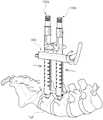
그리고 나서, 사용자가 제1 및 제2 작업 타워(100a)(100b)의 각 하단에 있는 제1 및 제2 교정 스크류(10a)(10b) 사이를 벌려 인장시키기를 원하면, 중심축(910)을 가압 바디(923)보다 아래에 위치되도록 하여 타워 받침대(930)를 제1 및 제2 작업 타워(100a)(100b) 사이에 삽입한 후, 도 36a에 도시된 바와 같이, 사용자가 구동 핸들(927)을 돌리면, 제1 및 제2 교정 스크류(10a)(10b) 사이가 벌어지면서 인장된다.Then, when the user desires to stretch between the first and second calibration screws 10a and 10b at the lower ends of the first and
한편, 사용자가 제1 및 제2 작업 타워(100a)(100b)의 각 하단에 있는 상기 제1 및 제2 교정 스크류(10a)(10b) 사이를 좁혀 압축시키기를 원하면, 중심축(910)을 가압 바디(923)보다 위에 위치되도록 하여 타워 받침대(930)를 제1 및 제2 작업 타워(100a)(100b) 사이에 삽입한 후, 도 36b에 도시된 바와 같이, 사용자가 구동 핸들(927)을 돌리면, 제1 및 제2 교정 스크류(10a)(10b) 사이가 좁혀지면서 압축된다.On the other hand, if the user wishes to narrow the gap between the first and second calibration screws 10a and 10b at the lower ends of the first and
10: 교정 스크류11: 로드 수납부
12: 헤드부13: 체결홈
20: 로드S: 셋 스크류
SP: 척추뼈100: 작업 타워
110: 외관120: 내관
130: 구동 슬리브140: 스크류 홀더
300, 500: 로드 인서터310: 고정 바
320: 이동 바330: 조절 노브
340, 510: 로드 홀더341: 후크
342: 로드 지지부343: 제1 홀딩 암
344: 제2 홀딩 암511: 너클
512: 로드 홀더 브라켓513: 클립
700: 로드 리듀서710: 외측 부재
711: 셋 스크류 장착부720: 내측 부재
721: 하단 인출부730: 체결 슬리브
740: 회전 핸들900: 인장압축기
910: 중심축920: 타워 가압 유닛
930: 타워 받침대10: calibration screw 11: rod compartment
12: head part 13: fastening groove
20: Load S: Set screw
SP: Spine Bone 100: Operation Tower
110: Appearance 120: Inner tube
130: drive sleeve 140: screw holder
300, 500: Rod inserter 310: Fixed bar
320: Movement bar 330: Adjustment knob
340, 510: rod holder 341: hook
342: rod support portion 343: first holding arm
344: second holding arm 511: knuckle
512: Rod holder bracket 513: Clip
700: rod reducer 710: outer member
711: Set screw mounting portion 720: Inner member
721: lower drawer 730: fastening sleeve
740: rotation handle 900: tension compressor
910: center shaft 920: tower pressurizing unit
930: Tower stand
Claims (34)
Translated fromKorean외관;
상기 외관의 내부에 슬라이딩 가능하게 구비되는 내관;
상기 외관에 회전 가능하게 연결되고 상기 내관에 나사 체결되어 회전시 상기 내관을 그 길이 방향을 따라 상하 이동시키는 구동 슬리브; 및
상기 내관의 하단부에 구비되며 상기 외관으로부터 인출되면 상기 교정 스크류의 헤드부를 수용할 수 있도록 자체 탄성에 의해 벌어지고 상기 외관으로 인입되면 상기 헤드부를 조일 수 있도록 수축되는 스크류 홀더를 포함하고,
상기 외관의 하반부는 제1 및 제2 외관 분지부로 나뉘어져 분지된 형상을 하고, 상기 내관의 하반부는 제1 및 제2 내관 분지부로 나뉘어져 분지된 형상을 하고, 상기 제1 및 제2 외관 분지부 사이의 제1 로드 안내홈과 상기 제1 및 제2 내관 분지부 사이의 제2 로드 안내홈은 서로 상응하도록 위치되어 상기 제1 및 제2 로드 안내홈을 통해 로드가 안내되는 작업 타워.A working tower that grasps the calibration screw during minimally invasive surgery and serves as a workstation for other external devices.
Exterior;
An inner tube slidably installed inside the outer tube;
A driving sleeve rotatably connected to the outer tube and screwed to the inner tube to move the inner tube upward and downward along the longitudinal direction when rotated; And
And a screw holder provided at a lower end of the inner tube and opened by self-elasticity to receive the head portion of the calibration screw when drawn out of the outer tube, and being contracted to be able to tighten the head portion when the outer tube is pulled,
Wherein the lower half of the outer tube has a branched shape divided into first and second outer branch portions and the lower half portion of the inner tube has a branched shape divided into first and second inner branch portions, Wherein the first rod guide groove between the first and second rod guide portions and the second rod guide groove between the first and second inner pipe branch portions are positioned to correspond to each other so that the rod is guided through the first and second rod guide grooves.
상기 스크류 홀더는 상기 제1 및 제2 내관 분지부의 단부에 각각 구비되는 제1 및 제2 홀딩 암을 포함하고, 상기 제1 및 제2 홀딩 암에는 상기 헤드부와 체결되기 위한 체결구가 형성되는 작업 타워.3. The method of claim 2,
The screw holder includes first and second holding arms respectively provided at the ends of the first and second inward branch branches, and the first and second holding arms have fasteners for fastening the head unit Working Towers.
상기 제1 및 제2 홀딩 암이 상기 외관으로부터 인출되어 자체 탄성에 의해 벌어질 경우 그 사이의 거리는 상기 헤드부의 외경 보다 큰 작업 타워.4. The method of claim 3,
Wherein a distance between the first and second holding arms is larger than an outer diameter of the head portion when the first and second holding arms are drawn out from the outer tube and opened by self-elasticity.
상기 내관과 상기 외관은 관 안내부에 의해 서로 좌우 회전됨 없이 상하 슬라이딩되며, 상기 관 안내부는 상기 제1 및 제2 외관 분지부의 내면에 각각 형성되어 상기 제1 및 제2 내관 분지부를 안내하는 내관 안내홈인 작업 타워.4. The method of claim 3,
The inner tube and the outer tube are slid up and down without being rotated left and right by the tube guide portion, and the tube guide portion is formed on the inner surface of the first and second outer tube branch portions, respectively, so that the first and second inner tube branch portions In the home guide work tower.
상기 제1 및 제2 외관 분지부의 단부 내면에 각각 상기 제1 및 제2 홀딩 암을 안착시킬 수 있는 홀딩암 안착홈이 형성되고, 상기 홀딩암 안착홈은 상기 내관 안내홈과 연결되는 작업 타워.The method of claim 5,
Wherein a holding arm receiving groove capable of receiving the first and second holding arms is formed on an inner surface of an end of the first and second outer branch portions, .
외관;
상기 외관의 내부에 슬라이딩 가능하게 구비되는 내관;
상기 외관에 회전 가능하게 연결되고 상기 내관에 나사 체결되어 회전시 상기 내관을 그 길이 방향을 따라 상하 이동시키는 구동 슬리브; 및
상기 내관의 하단부에 구비되며 상기 외관으로부터 인출되면 상기 교정 스크류의 헤드부를 수용할 수 있도록 자체 탄성에 의해 벌어지고 상기 외관으로 인입되면 상기 헤드부를 조일 수 있도록 수축되는 스크류 홀더를 포함하고,
상기 구동 슬리브의 상단 내주면에는 수나사가 형성되고, 상기 수나사와 상응하도록 상기 내관의 외주면에는 슬리브 체결용 암나사가 형성되며, 제1 외부 기기와의 나사 체결을 위해 상기 내관의 외주연 중 상기 슬리브 체결용 암나사와 이격된 부위에 외부 기기 체결용 암나사가 형성되는 작업 타워.A working tower that grasps the calibration screw during minimally invasive surgery and serves as a workstation for other external devices.
Exterior;
An inner tube slidably installed inside the outer tube;
A driving sleeve rotatably connected to the outer tube and screwed to the inner tube to move the inner tube upward and downward along the longitudinal direction when rotated; And
And a screw holder provided at a lower end of the inner tube and opened by self-elasticity to receive the head portion of the calibration screw when drawn out of the outer tube, and being contracted to be able to tighten the head portion when the outer tube is pulled,
A male screw is formed on an upper inner circumferential surface of the drive sleeve and a female screw for fastening the sleeve is formed on the outer circumferential surface of the inner pipe so as to correspond to the male screw, A working tower in which a female thread for fastening an external device is formed at a spaced apart position from the female thread.
상기 외부 기기 체결용 암나사는 상기 슬리브 체결용 암나사보다 상기 내관의 상부에 형성되는 작업 타워.8. The method of claim 7,
Wherein the external device fastening female thread is formed on the upper portion of the inner tube than the sleeve fastening female thread.
상기 수나사가 상기 외부 기기 체결용 암나사와 상기 슬리브 체결용 암나사 사이에 위치되면 상기 내관을 당기거나 누르는 방식에 의해 상기 스크류 홀더가 상기 외관으로부터 인입출되고, 상기 내관이 눌려 상기 슬리브 체결용 암나사가 상기 구동 슬리브의 하단에 걸리면 상기 스크류 홀더는 상기 외관으로부터 인출이 완료되며, 상기 내관이 당겨진 후 상기 수나사가 상기 슬리브 체결용 암나사에 체결되면 상기 스크류 홀더는 상기 외관으로부터 인입이 완료되는 작업 타워.9. The method of claim 8,
When the male screw is positioned between the female screw for fastening the external device and the female screw for fastening the sleeve, the screw holder is pulled out from the outer tube by pulling or pushing the inner tube, and the inner tube is pushed, Wherein the screw holder is pulled out from the outer tube when the lower end of the driving sleeve is hooked and the screw holder is pulled out from the outer tube when the male screw is fastened to the sleeve fastening female screw after the inner tube is pulled.
Priority Applications (3)
| Application Number | Priority Date | Filing Date | Title |
|---|---|---|---|
| KR1020120100966AKR101419807B1 (en) | 2012-09-12 | 2012-09-12 | working tower for minimally invasive surgery system |
| US13/653,400US20140074106A1 (en) | 2012-09-12 | 2012-10-16 | Working tower, rod inserter, rod reducer, and compression-distraction tool for minimally invasive surgery system |
| PCT/KR2013/007879WO2014042374A2 (en) | 2012-09-12 | 2013-09-02 | Operation tower for minimally invasive surgical system, rod inserter, rod reducer, and tension compression device |
Applications Claiming Priority (1)
| Application Number | Priority Date | Filing Date | Title |
|---|---|---|---|
| KR1020120100966AKR101419807B1 (en) | 2012-09-12 | 2012-09-12 | working tower for minimally invasive surgery system |
Related Child Applications (3)
| Application Number | Title | Priority Date | Filing Date |
|---|---|---|---|
| KR1020130155830ADivisionKR101464617B1 (en) | 2013-12-13 | 2013-12-13 | Compression-distraction tool for minimally invasive surgery system |
| KR1020130155828ADivisionKR101464618B1 (en) | 2013-12-13 | 2013-12-13 | Rod inserter for minimally invasive surgery system |
| KR1020130155829ADivisionKR101434333B1 (en) | 2013-12-13 | 2013-12-13 | Rod reducer for minimally invasive surgery system |
Publications (2)
| Publication Number | Publication Date |
|---|---|
| KR20140035009A KR20140035009A (en) | 2014-03-21 |
| KR101419807B1true KR101419807B1 (en) | 2014-07-21 |
Family
ID=50234060
Family Applications (1)
| Application Number | Title | Priority Date | Filing Date |
|---|---|---|---|
| KR1020120100966AActiveKR101419807B1 (en) | 2012-09-12 | 2012-09-12 | working tower for minimally invasive surgery system |
Country Status (3)
| Country | Link |
|---|---|
| US (1) | US20140074106A1 (en) |
| KR (1) | KR101419807B1 (en) |
| WO (1) | WO2014042374A2 (en) |
Cited By (5)
| Publication number | Priority date | Publication date | Assignee | Title |
|---|---|---|---|---|
| KR101662789B1 (en) | 2015-08-31 | 2016-10-05 | 주식회사 메드릭스 | Rod inserter for fixing of pedicle screw and apparatus of minimal invasive surgery using this |
| KR101703003B1 (en) | 2015-08-31 | 2017-02-06 | 주식회사 메드릭스 | Screw holder with joint for minimal invasive surgery and apparatus of minimal invasive surgery using this |
| KR101703004B1 (en) | 2015-08-31 | 2017-02-06 | 주식회사 메드릭스 | Screw reducer for minimal invasive surgery and apparatus of minimal invasive surgery using this |
| US9913670B2 (en) | 2015-08-31 | 2018-03-13 | Mantiz Logitech Co., Ltd. | Rod inserter for fixing of pedicle screw, screw holder with joint for minimal invasive surgery, screw reducer for minimal invasive surgery and apparatus for minimal invasive surgery using these devices |
| WO2025018540A1 (en)* | 2023-07-20 | 2025-01-23 | (주)시지바이오 | Pedicle screw assembly |
Families Citing this family (33)
| Publication number | Priority date | Publication date | Assignee | Title |
|---|---|---|---|---|
| US8439922B1 (en) | 2008-02-06 | 2013-05-14 | NiVasive, Inc. | Systems and methods for holding and implanting bone anchors |
| FR2954689B1 (en)* | 2009-12-28 | 2012-12-21 | Sterispine | DEVICE AND METHOD FOR SPINAL SURGERY. |
| US9198698B1 (en)* | 2011-02-10 | 2015-12-01 | Nuvasive, Inc. | Minimally invasive spinal fixation system and related methods |
| US9907582B1 (en) | 2011-04-25 | 2018-03-06 | Nuvasive, Inc. | Minimally invasive spinal fixation system and related methods |
| US9125703B2 (en)* | 2012-01-16 | 2015-09-08 | K2M, Inc. | Rod reducer, compressor, distractor system |
| US9486256B1 (en) | 2013-03-15 | 2016-11-08 | Nuvasive, Inc. | Rod reduction assemblies and related methods |
| US10136927B1 (en) | 2013-03-15 | 2018-11-27 | Nuvasive, Inc. | Rod reduction assemblies and related methods |
| US9655659B2 (en)* | 2013-04-20 | 2017-05-23 | Degen Medical, Inc. | Anchor tower |
| US9526536B2 (en)* | 2013-10-16 | 2016-12-27 | Spineology Inc. | Articulating rod holder |
| US20160058482A1 (en) | 2014-08-07 | 2016-03-03 | Jeffrey Scott Smith | Rod delivery tool for use in pedicle screw systems |
| WO2016025408A2 (en)* | 2014-08-11 | 2016-02-18 | Spinal Elements, Inc | Articulating rod inserter |
| WO2016077208A1 (en)* | 2014-11-10 | 2016-05-19 | Spinal Usa, Inc. | Percutaneous rod inserter and method of use |
| US9974577B1 (en) | 2015-05-21 | 2018-05-22 | Nuvasive, Inc. | Methods and instruments for performing leveraged reduction during single position spine surgery |
| US10123829B1 (en) | 2015-06-15 | 2018-11-13 | Nuvasive, Inc. | Reduction instruments and methods |
| US10194960B1 (en) | 2015-12-03 | 2019-02-05 | Nuvasive, Inc. | Spinal compression instrument and related methods |
| US9795422B2 (en)* | 2016-01-06 | 2017-10-24 | Aesculap Implant Systems, Llc | Rod inserter, system and method |
| CN106037904B (en)* | 2016-06-20 | 2018-10-12 | 上海歆业昉维科技有限公司 | A kind of calcaneal traction navigation device |
| DE102016011521A1 (en)* | 2016-09-23 | 2018-03-29 | Silony Medical International AG | Stabeinbringinstrument with adjustable rod angulation |
| US10398481B2 (en) | 2016-10-03 | 2019-09-03 | Nuvasive, Inc. | Spinal fixation system |
| CN106473783B (en)* | 2016-11-22 | 2020-01-14 | 常州华森医疗器械有限公司 | Distraction piece for pedicle of vertebral arch fixing system |
| US10779866B2 (en) | 2016-12-29 | 2020-09-22 | K2M, Inc. | Rod reducer assembly |
| CN107049434B (en)* | 2017-05-25 | 2018-06-08 | 张婷英 | Percutaneous renal puncture locator |
| CN107049435B (en)* | 2017-05-25 | 2018-09-07 | 朱飞龙 | Percutaneous renal puncture locator |
| US10610269B2 (en) | 2017-09-05 | 2020-04-07 | Medos International Sarl | Modular surgical instruments and related methods |
| US10966762B2 (en) | 2017-12-15 | 2021-04-06 | Medos International Sarl | Unilateral implant holders and related methods |
| EP3517062B1 (en)* | 2018-01-26 | 2021-03-17 | Aesculap AG | Spinal repositioning instrument and spinal repositioning system |
| US11051861B2 (en) | 2018-06-13 | 2021-07-06 | Nuvasive, Inc. | Rod reduction assemblies and related methods |
| US11291481B2 (en) | 2019-03-21 | 2022-04-05 | Medos International Sarl | Rod reducers and related methods |
| USD1004774S1 (en) | 2019-03-21 | 2023-11-14 | Medos International Sarl | Kerrison rod reducer |
| US11291482B2 (en) | 2019-03-21 | 2022-04-05 | Medos International Sarl | Rod reducers and related methods |
| CN111658105A (en)* | 2020-06-09 | 2020-09-15 | 南京市儿童医院 | A press excellent device for backbone deformity correction operation |
| EP4240262B1 (en) | 2020-11-09 | 2024-12-04 | Medos International Sàrl | Biplanar forceps reducers |
| JP2024508548A (en)* | 2021-03-05 | 2024-02-27 | メドス・インターナショナル・エスエイアールエル | sequential reducer |
Citations (4)
| Publication number | Priority date | Publication date | Assignee | Title |
|---|---|---|---|---|
| US20060074418A1 (en) | 2004-09-24 | 2006-04-06 | Jackson Roger P | Spinal fixation tool set and method for rod reduction and fastener insertion |
| JP2009505748A (en) | 2005-08-25 | 2009-02-12 | ジンテス ゲゼルシャフト ミット ベシュレンクテル ハフツング | Spine fixation system instrument and method of use |
| US20100036443A1 (en) | 2007-10-23 | 2010-02-11 | Alphatec Spine, Inc. | Systems and methods for spinal fixation |
| US20110184469A1 (en) | 2010-01-28 | 2011-07-28 | Warsaw Orthopedic, Inc. | Set screw alignment tool |
Family Cites Families (5)
| Publication number | Priority date | Publication date | Assignee | Title |
|---|---|---|---|---|
| US7887539B2 (en)* | 2003-01-24 | 2011-02-15 | Depuy Spine, Inc. | Spinal rod approximators |
| EP1858422A4 (en)* | 2005-02-23 | 2011-12-28 | Pioneer Surgical Technology Inc | Minimally invasive surgical system |
| US7758617B2 (en)* | 2005-04-27 | 2010-07-20 | Globus Medical, Inc. | Percutaneous vertebral stabilization system |
| US7686809B2 (en)* | 2006-09-25 | 2010-03-30 | Stryker Spine | Rod inserter and rod with reduced diameter end |
| US8246624B2 (en)* | 2009-07-23 | 2012-08-21 | Zimmer Spine, Inc. | Spinal rod insertion tool and method |
- 2012
- 2012-09-12KRKR1020120100966Apatent/KR101419807B1/enactiveActive
- 2012-10-16USUS13/653,400patent/US20140074106A1/ennot_activeAbandoned
- 2013
- 2013-09-02WOPCT/KR2013/007879patent/WO2014042374A2/enactiveApplication Filing
Patent Citations (4)
| Publication number | Priority date | Publication date | Assignee | Title |
|---|---|---|---|---|
| US20060074418A1 (en) | 2004-09-24 | 2006-04-06 | Jackson Roger P | Spinal fixation tool set and method for rod reduction and fastener insertion |
| JP2009505748A (en) | 2005-08-25 | 2009-02-12 | ジンテス ゲゼルシャフト ミット ベシュレンクテル ハフツング | Spine fixation system instrument and method of use |
| US20100036443A1 (en) | 2007-10-23 | 2010-02-11 | Alphatec Spine, Inc. | Systems and methods for spinal fixation |
| US20110184469A1 (en) | 2010-01-28 | 2011-07-28 | Warsaw Orthopedic, Inc. | Set screw alignment tool |
Cited By (5)
| Publication number | Priority date | Publication date | Assignee | Title |
|---|---|---|---|---|
| KR101662789B1 (en) | 2015-08-31 | 2016-10-05 | 주식회사 메드릭스 | Rod inserter for fixing of pedicle screw and apparatus of minimal invasive surgery using this |
| KR101703003B1 (en) | 2015-08-31 | 2017-02-06 | 주식회사 메드릭스 | Screw holder with joint for minimal invasive surgery and apparatus of minimal invasive surgery using this |
| KR101703004B1 (en) | 2015-08-31 | 2017-02-06 | 주식회사 메드릭스 | Screw reducer for minimal invasive surgery and apparatus of minimal invasive surgery using this |
| US9913670B2 (en) | 2015-08-31 | 2018-03-13 | Mantiz Logitech Co., Ltd. | Rod inserter for fixing of pedicle screw, screw holder with joint for minimal invasive surgery, screw reducer for minimal invasive surgery and apparatus for minimal invasive surgery using these devices |
| WO2025018540A1 (en)* | 2023-07-20 | 2025-01-23 | (주)시지바이오 | Pedicle screw assembly |
Also Published As
| Publication number | Publication date |
|---|---|
| WO2014042374A3 (en) | 2014-05-08 |
| US20140074106A1 (en) | 2014-03-13 |
| WO2014042374A2 (en) | 2014-03-20 |
| KR20140035009A (en) | 2014-03-21 |
Similar Documents
| Publication | Publication Date | Title |
|---|---|---|
| KR101419807B1 (en) | working tower for minimally invasive surgery system | |
| US11058465B2 (en) | Tool system for dynamic spinal implants | |
| KR101434333B1 (en) | Rod reducer for minimally invasive surgery system | |
| US7618442B2 (en) | Implant assembly and method for use in an internal structure stabilization system | |
| US7967826B2 (en) | Connector transfer tool for internal structure stabilization systems | |
| CN103717159B (en) | Minimally Invasive Spinal Fixation System Including Vertebral Alignment Features | |
| US20080255576A1 (en) | Multiple implant dispensing driver | |
| US20110190822A1 (en) | Internal Structure Stabilization System for Spanning Three or More Structures | |
| US20050085813A1 (en) | System and method for stabilizing of internal structures | |
| EP2120756A2 (en) | Multiple implant dispensing driver | |
| KR101464617B1 (en) | Compression-distraction tool for minimally invasive surgery system | |
| KR101464618B1 (en) | Rod inserter for minimally invasive surgery system | |
| CN115429380A (en) | Pedicle of vertebral arch fixed channel device for minimal access spine operation | |
| AU2011211374B2 (en) | Tool system for dynamic spinal implants |
Legal Events
| Date | Code | Title | Description |
|---|---|---|---|
| A201 | Request for examination | ||
| PA0109 | Patent application | Patent event code:PA01091R01D Comment text:Patent Application Patent event date:20120912 | |
| PA0201 | Request for examination | ||
| E902 | Notification of reason for refusal | ||
| PE0902 | Notice of grounds for rejection | Comment text:Notification of reason for refusal Patent event date:20131025 Patent event code:PE09021S01D | |
| A107 | Divisional application of patent | ||
| PA0107 | Divisional application | Comment text:Divisional Application of Patent Patent event date:20131213 Patent event code:PA01071R01D | |
| PG1501 | Laying open of application | ||
| E701 | Decision to grant or registration of patent right | ||
| PE0701 | Decision of registration | Patent event code:PE07011S01D Comment text:Decision to Grant Registration Patent event date:20140408 | |
| GRNT | Written decision to grant | ||
| PR0701 | Registration of establishment | Comment text:Registration of Establishment Patent event date:20140709 Patent event code:PR07011E01D | |
| PR1002 | Payment of registration fee | Payment date:20140710 End annual number:3 Start annual number:1 | |
| PG1601 | Publication of registration | ||
| FPAY | Annual fee payment | Payment date:20170704 Year of fee payment:4 | |
| PR1001 | Payment of annual fee | Payment date:20170704 Start annual number:4 End annual number:4 | |
| FPAY | Annual fee payment | Payment date:20180709 Year of fee payment:5 | |
| PR1001 | Payment of annual fee | Payment date:20180709 Start annual number:5 End annual number:5 | |
| FPAY | Annual fee payment | Payment date:20190611 Year of fee payment:6 | |
| PR1001 | Payment of annual fee | Payment date:20190611 Start annual number:6 End annual number:6 | |
| PR1001 | Payment of annual fee | Payment date:20200615 Start annual number:7 End annual number:7 | |
| PR1001 | Payment of annual fee | Payment date:20210616 Start annual number:8 End annual number:8 | |
| PR1001 | Payment of annual fee | Payment date:20220620 Start annual number:9 End annual number:9 | |
| PR1001 | Payment of annual fee | Payment date:20240619 Start annual number:11 End annual number:11 | |
| PR1001 | Payment of annual fee | Payment date:20250702 Start annual number:12 End annual number:12 |