Movatterモバイル変換


[0]ホーム

URL:


KR101417144B1 - Multiple heater control system with expandable modular functionality - Google Patents

Multiple heater control system with expandable modular functionality
Download PDF

Info

Publication number
KR101417144B1
KR101417144B1KR1020087026979AKR20087026979AKR101417144B1KR 101417144 B1KR101417144 B1KR 101417144B1KR 1020087026979 AKR1020087026979 AKR 1020087026979AKR 20087026979 AKR20087026979 AKR 20087026979AKR 101417144 B1KR101417144 B1KR 101417144B1
Authority
KR
South Korea
Prior art keywords
heater
power
temperature
circuit
upper limit
Prior art date
Legal status (The legal status is an assumption and is not a legal conclusion. Google has not performed a legal analysis and makes no representation as to the accuracy of the status listed.)
Active
Application number
KR1020087026979A
Other languages
Korean (ko)
Other versions
KR20090013184A (en
Inventor
유팬 구
제프리 디. 키어넌
찰스 씨. 로헤드
윌리암 씨. 보링거
에릭 이. 엘리스
커티스 에이. 포스터
제임스 피. 헨체스
마크 루이스길머 호벤
제임스 에이치. 크리셀
숀 레닝거
로버트 오. 모랜
커트 더블유. 피터슨
제이슨 알. 파월
데일 티. 울프
Original Assignee
엠케이에스 인스트루먼츠, 인코포레이티드
와틀로 일렉트릭 매뉴팩츄어링 컴파니
Priority date (The priority date is an assumption and is not a legal conclusion. Google has not performed a legal analysis and makes no representation as to the accuracy of the date listed.)
Filing date
Publication date
Application filed by 엠케이에스 인스트루먼츠, 인코포레이티드, 와틀로 일렉트릭 매뉴팩츄어링 컴파니filedCritical엠케이에스 인스트루먼츠, 인코포레이티드
Publication of KR20090013184ApublicationCriticalpatent/KR20090013184A/en
Application grantedgrantedCritical
Publication of KR101417144B1publicationCriticalpatent/KR101417144B1/en
Activelegal-statusCriticalCurrent
Anticipated expirationlegal-statusCritical

Links

Images

Classifications

Landscapes

Abstract

Translated fromKorean

본 발명의 다수 히터 제어 시스템(10)은 케이블(26), 커넥터(64, 78, 82, 86), 및 개별 제어 히터 시리즈 및/또는 마스터 및 슬레이브 히터 시리즈의 다양한 구성 또는 조합에 의한 히터 제어기(20)와 히터(16)의 사용자 친화적인 데이지 체인 접속을 위한 접속 배선함을 포함한다. 히터 제어기는 히터로의 AC 전력의 처리 제어 및 처리 제어로부터 실질적으로 독립된 상한 안전 차단을 포함한다. 히터 제어기는 또한 베이스 모듈에 탈착가능한 확장 모듈에 의해 다양한 레벨로 확장가능한 베이스 모듈 내에 변경가능한 레벨의 제어, 조정, 디스플레이, 및 통신 기능성을 갖는다. 커넥터, 케이블 및 접합 구성, 어댑터 및 랫치 특징부는 사용자 친화성을 향상시킨다.

Figure R1020087026979

히터, 제어기, 베이스 모듈, 확장 모듈, 케이블, 커넥터

The multiple heater control system 10 of the present invention includes a heater controller (not shown) by various configurations or combinations of cable 26, connectors 64, 78, 82, 86, and individual control heater series and / or master and slave heater series 20 for the user-friendly daisy-chain connection of the heater 16. The heater controller includes an upper limit safety cutout substantially independent of process control and process control of AC power to the heater. The heater controller also has a controllable level of control, adjustment, display, and communication functionality in the base module that can be extended to various levels by a removable expansion module in the base module. Connectors, cables and bonding configurations, adapters and latch features enhance user friendliness.

Figure R1020087026979

Heater, controller, base module, extension module, cable, connector

Description

Translated fromKorean
확장가능한 모듈 기능성을 가진 다수 히터 제어 시스템{MULTIPLE HEATER CONTROL SYSTEM WITH EXPANDABLE MODULAR FUNCTIONALITY}[0001] MULTIPLE HEATER CONTROL SYSTEM WITH EXPANDABLE MODULAR FUNCTIONALITY [0002]

본 발명은 히터용 전력 및 제어 시스템에 관한 것으로, 예를 들어 진공, 처리, 전달, 이송 및 기타 시스템 내의 가열 파이프 및 기타 구성요소를 위해 사용되는 다수의 히터에 전력을 공급하고 제어하기 위한 장치 및 방법에 관한 것이다.The present invention relates to a power and control system for a heater, and more particularly to an apparatus and system for powering and controlling a plurality of heaters used for heating pipes and other components in, for example, vacuum, process, transfer, ≪ / RTI >

한 지점에서 다른 지점으로 다양한 기체, 액체 또는 고체 재료를 유도 또는 이동시키는 산업에 사용되는 많은 진공, 처리, 전달, 이송 및 기타 시스템은 파이프 및/또는 파이프 내의 재료를 특정 온도 범위 내에 유지하도록 가열되어야 하는 다양한 길이, 크기 및 형상의 파이프를 포함한다. 이러한 목적 및 기타 목적을 위해 파이프를 가열하기 위한 파이프 히터는 당업자에게 잘 알려져 있으며, 간단한 저항선 및 파이프 둘레에 감긴 테이프로부터, 본원에 참고로 합체된 미국 특허 제5,714,738호[하우슐츠(Hauschultz) 등]에 개시된 것과 같은 더욱 복잡한 절연 파이프 히터 및 상업적으로 구입가능한 많은 그러한 히터 제품까지 아우른다.Many vacuum, treatment, transfer, transfer, and other systems used in industries to guide or transfer various gas, liquid or solid materials from one point to another must be heated to maintain the material in the pipe and / or pipe within a certain temperature range And pipes of various lengths, sizes and shapes. Pipe heaters for heating pipes for this and other purposes are well known to those skilled in the art and are described in U.S. Patent No. 5,714,738 (Hauschultz et al.), Incorporated herein by reference, from a simple resistance wire and tape wrapped around the pipe, , And many such commercially available heater products.

다양한 파이프 가열 응용예를 위한 파이프 히터의 발전과 함께, 파이프의 길이를 따라 히터로부터 출력되는 열을 조절하고 그러한 히터 동작을 모니터링 및 제어하기 위한 보다 양호한 파이프 히터 제어 시스템에 대한 요구가 또한 존재하였 다. 그러한 히터 제어 시스템에는 본원에 참고로 합체된 미국 특허 제6,894,254(하우슐츠)에 설명된 것과 같은 많은 종류와 구성의 것이 존재한다. 그러나, 그러한 히터 모니터링 및 제어 시스템이 우수하긴 하지만, 해결하지 못한 문제들이 여전히 존재한다.With the development of pipe heaters for various pipe heating applications, there was also a need for a better pipe heater control system for controlling the heat output from the heaters along the length of the pipe and for monitoring and controlling such heater operation . There are many types and configurations of such heater control systems, such as those described in U.S. Patent No. 6,894,254 (Howlsch), which is incorporated herein by reference. However, although such heater monitoring and control systems are excellent, there are still problems that can not be solved.

예를 들어, 고온 설비에서, 파이프 히터에 의해 발생된 열은 파이프 히터 상에 직접 장착된 열 제어기 구성요소로 전도될 수 있고, 그리하여 그러한 제어기 구성요소를 손상 또는 파괴하거나 제어기 시스템 내의 로직 회로 또는 메모리 내의 데이터를 변조 또는 열화시킬 수 있는 레벨까지 그러한 제어기 구성요소의 온도를 잠재적으로 상승시킨다. 몇몇 전력 제어 시스템은 시스템의 히터 구성요소에 배선에 의해 접속되어 신속히 교체하는 것을 어렵게 한다. 또한, 대부분의 공업용 파이프 히터는 열 상한 퓨즈 또는 열 활성화 스위치를 구비하며, 이것은 사람의 안전을 위해, 중요한 설비의 손상을 방지하기 위해, 그리고 안전 기관 인증을 위해, 원인에 관계없이 최대 온도 역치에 도달한 경우에 파이프 히터로의 전력을 끊는다. 이러한 기능은 다양한 열 제한 장치에 제공되었지만, 그 중 어느 것도 이 응용예에 완전히 만족스럽지 못 하였다.For example, in a high temperature facility, the heat generated by the pipe heater may be conducted to a thermal controller component mounted directly on the pipe heater, thereby damaging or destroying such controller component, Lt; RTI ID = 0.0 > temperature < / RTI > Some power control systems are connected by wires to the heater components of the system, making it difficult to quickly replace them. In addition, most industrial pipe heaters have a thermally insulated fuse or a thermally activated switch, which can be used for human safety, to prevent damage to critical equipment, and for safety agency certification, When reaching, the power to the pipe heater is cut off. This function has been provided for a variety of thermal limiting devices, none of which have been completely satisfactory for this application.

예를 들어, 상업적으로 구입가능한 표준적인 열 스위치는 부식되거나, 또는 더욱 나쁘게는 폐쇄 상태로 자체 용접되어 완전히 작동 불가능하게 하거나 히터 요소가 연소 또는 발화할 때까지 히터의 열 탈출을 허용할 수 있는 넓은 설정 포인트 공차 및 접촉 기구로 인해 부정확하고 신뢰할 수 없다. 이 문제점들은 열 스위치가 히터 및 파이프의 실제 온도에 대한 정확한 응답을 위해 배치되어야 할 히터 내 에 또는 히터 상에 배치될 때 악화되는데, 이는 히터에서의 고열이 열 스위치의 열화의 주요 원인이기 때문이다. 여전히, 열 스위치는 히터로부터 떨어져 또는 멀리에 배치될 수 없는데, 이는 열 스위치가 히터 또는 파이프의 실제 온도에 응답할 수 없기 때문이다.For example, a commercially available standard thermal switch may be corroded or, worse yet, self-welded to a closed state to make it completely inoperable, or it may be widespread to permit heat escape of the heater until the heater element is burned or ignited. Set point tolerance and contact mechanism are inaccurate and unreliable. These problems are exacerbated when the heat switch is placed in or on the heater to be placed for an accurate response to the actual temperature of the heater and the pipe because the high temperature in the heater is the main cause of the deterioration of the heat switch . Still, the thermal switch can not be placed away from or away from the heater because the thermal switch can not respond to the actual temperature of the heater or pipe.

열 퓨즈는 더욱 신뢰성 있고 상업적으로 구입 가능하지만, 일단 소실되면, 즉 "끊어지거나" 또는 "타버리면", 리셋될 수 없다. 열 퓨즈는 일반적으로 열원 근처에서 열에 확실히 노출되도록 가열 요소 근처에서 파이프 히터 구조체에 매설되기 때문에, 히터 구성요소 및 재료의 파괴 없이는 접근 불가능하다. 따라서, 끊어지거나 타버린 열 퓨즈가 히터를 완전히 쓸모없게 만들어 교체해야만 한다. 또한, 열 퓨즈는 시간 경과에 따라 노화되며, 더 높은 온도에 노출될수록 더 빨리 노화된다. 그러한 노화는 종종 열 퓨즈가 낮은 온도에서 타버리게 하며, 결국 파이프 히터의 정상 작동 범위 내에서 타버리게 하여, 양호한 파이프 히터를 사용 불가능하게 한다. 또한, 상업적으로 구입 가능한 열 퓨즈는 부피가 크고 파이프 히터 내에 설치하기가 어렵다.Thermal fuses are more reliable and commercially available, but can not be reset once they are lost, that is, "broken" or "burned". Thermal fuses are generally inaccessible without destruction of heater components and materials because they are buried in the pipe heater structure near the heating element so as to be reliably exposed to heat near the heat source. Therefore, a broken or burned thermal fuse must be replaced to make the heater completely useless. Also, thermal fuses aging with time, and aging more rapidly when exposed to higher temperatures. Such aging often causes the thermal fuse to burn at low temperatures and eventually burn out within the normal operating range of the pipe heater, rendering the good pipe heater unusable. In addition, commercially available thermal fuses are bulky and difficult to install in pipe heaters.

파이프의 온도, 그리고 따라서 파이프 히터의 온도가 탈출 또는 제어 불가능한 히터와 관계없는 그러한 온도 상한을 초과하게 하는 상황이 종종 존재한다. 예를 들어, 파이프 시스템으로부터 상류의 처리 챔버에 고온 기체 또는 반응성 화학물질을 통과시킴으로써 처리 챔버를 정화 또는 세척하는 것은 일반적이지 않으며, 이것은 파이프 온도, 그리고 따라서 파이프 히터 온도가 또한 온도 상한을 일시적으로 초과하게 하여 열 퓨즈가 소실되고 전력 회로가 개방되게 하여 히터를 불능화 할 수 있다. 열 퓨즈가 소실되고 리셋 또는 교체될 수 없을 때, 양호한 히터는 그러한 일상적인 유지보수 및 파이프 히터 자체와 관련이 없는 기타 사건에 의해 파괴될 수 있다.There is often a situation where the temperature of the pipe, and thus the temperature of the pipe heater, exceeds such a temperature upper limit that is not related to escape or uncontrollable heaters. For example, it is not uncommon to purge or clean the process chamber by passing hot gases or reactive chemicals through the upstream processing chamber from the piping system, which is not uncommon because the pipe temperature, and thus the pipe heater temperature, also temporarily exceeds the upper temperature limit So that the thermal fuse is lost and the power circuit is opened, thereby disabling the heater. When a thermal fuse is lost and can not be reset or replaced, a good heater may be destroyed by such routine maintenance and other events not related to the pipe heater itself.

또한, 다양한 배관 구조, 응용예 및 사용자 요구를 수용하기 위해 접속 및 제어 구성 모두에 있어서 더 많은 옵션과 융통성이 필요하다. 각 파이프의 설치는 상이하며, 많은 조작자들은 특정 요건을 수용하기 위해 맞춤형 파이프 히터 및 제어 시스템을 필요로 하지만, 맞춤형 파이프 히터 시스템을 설계 및 제조하는 것은 비싸고, 시간이 소요되며, 대부분의 응용예에 적합하지 않을 때도 있다. 예를 들어, 일부 조작자들은 가열된 파이프 시스템 내의 각 가열기에 대해 제어 기구를 원하는 반면, 다른 조작자들은 각 히터에 대한 개별 제어의 비용을 회피하고, 그 대신에 다수의 개별 히터를 포함하는 전체 구역을 조작하는데 단일 제어기가 사용되는 전략을 사용하는 것을 선호한다. 그러한 "구역" 또는 "단일 포인트" 제어 히터 시스템은 종종 복잡한 배선을 요구하며, 이는 혼동을 야기하고 배선 오류의 가능성을 증가시킬 수 있거나, 맞춤형 히터가 슬레이빙을 수용하고 배선 오류를 방지하도록 설계 및 구축되는 것을 요구하여 비용을 증가시키고 시스템에 복잡성을 더할 수 있다.In addition, more options and flexibility are needed in both connection and control configurations to accommodate various piping structures, applications, and user needs. Although the installation of each pipe is different and many operators require customized pipe heaters and control systems to accommodate specific requirements, it is expensive, time consuming to design and manufacture a customized pipe heater system, Sometimes it is not appropriate. For example, some operators want a control mechanism for each heater in a heated pipe system, while other operators avoid the cost of individual controls for each heater, and instead use the entire zone containing multiple individual heaters I prefer to use a strategy where a single controller is used to operate. Such "zone" or "single point" control heater systems often require complicated wiring, which can lead to confusion and increase the likelihood of wiring errors, or that the customized heater is designed and / It can be costly to build and add complexity to the system.

다른 예는 일부 조작자들은 멀리 떨어진 위치에서 작동 상태 정보를 보고 작동 파라미터를 수정할 수 있도록 히터 제어기와의 원격 통신 및 원격 히터 시스템 제어 능력을 요구하는 반면, 다른 조작자들은 시스템 내의 각각의 히터에서 국지적으로 그러한 작동 상태 정보를 보고 작동 파라미터를 수정할 수 있을 것을 원한다. 또 다른 조작자들은 각각의 히터에 기초적인 사전 프로그래밍된 제어만을 요구한다. 물론, 단일 포인트 제어만을 가진 히터의 그룹에 대해 이 기능들의 임의의 조합 또는 전부를 원하는 조작자들도 존재한다.Another example is that some operators require remote communication with the heater controller and ability to control the remote heater system to view operating status information and modify operating parameters at a remote location while other operators may be required to locally You want to be able to view operating status information and modify operational parameters. Other operators require only pre-programmed controls based on each heater. Of course, there are operators who desire any combination or all of these functions for a group of heaters having only a single point control.

파이프 히터의 공업적 그리고 상업적 사용에 있어서의 이상의 요건 및 기타 요구는 다양한 조작자 요구에 부합하도록 용이하고 간소하며 효과적으로 구성될 수 있는 파이프 히터 제어기 및 배선 구성요소의 더 융통성 있는 시스템에 대한 요구를 발생시킨다.The above requirements and other requirements in the industrial and commercial use of pipe heaters create a need for a more flexible system of pipe heater controllers and wiring components that can be easily, simply and effectively configured to meet a variety of operator needs .

첨부된 도면은 명세서에 포함되어 그 일부를 구성하며, 상세한 설명을 뒷받침하도록 제시된 몇 가지 예시적인 실시예 및/또는 구성요소를 도시하지만, 어떠한 방식으로도 청구범위를 제한하지 않는다.BRIEF DESCRIPTION OF THE DRAWINGS The accompanying drawings, which are incorporated in and form a part of the specification, illustrate several example embodiments and / or components that are shown to support detailed description, and are not intended to limit the scope of the claims in any manner.

도1은 다수 히터 제어 시스템의 예시적인 개별 히터 제어 구성의 등각도이다.Figure 1 is an isometric view of an exemplary individual heater control configuration of a multiple heater control system.

도2는 도1에 도시된 것과 같은 개별 히터 제어 구성에 사용되는 주요 구성요소 중 일부의 등각도이다.Figure 2 is an isometric view of some of the major components used in an individual heater control configuration such as that shown in Figure 1;

도3은 도2의 주요 구성요소들의 등각도로서, 접속 구성요소를 도시하기 위해 상이한 시점에서 본 도면이다.Figure 3 is an isometric view of the major components of Figure 2, seen at different points in time to illustrate the connecting components.

도4는 조립 상태에 있는 도1의 개별 히터 제어 장치의 등각도이다.Figure 4 is an isometric view of the individual heater control device of Figure 1 in an assembled state.

도5는 마스터 히터 및 하나 이상의 슬레이브 히터를 포함하는 군집 또는 구역을 제어하는데 단일 포인트 히터 제어가 사용되는 다수 히터 제어 시스템의 예시 적인 구성의 등각도이다.5 is an isometric view of an exemplary configuration of a multiple heater control system in which a single point heater control is used to control a cluster or zone comprising a master heater and one or more slave heaters.

도6은 도5에 도시된 것과 같은 마스터 및 슬레이브 히터 조합을 위한 단일 포인트 제어 구성에 사용되는 주요 구성요소들 중 일부의 등각도이다.6 is an isometric view of some of the key components used in a single point control configuration for a master and slave heater combination as shown in FIG.

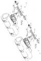
도7은 도6에 도시된 주요 구성요소의 등각도로서, 접속 구성요소를 도시하기 위해 상이한 시점에서 본 도면이다.Fig. 7 is an isometric view of the main components shown in Fig. 6, taken at different viewpoints to show the connecting components. Fig.

도8은 조립된 상태에 있는 도5의 마스터 및 슬레이브 히터 장치를 위한 단일 포인트 제어 장치의 등각도이다.Figure 8 is an isometric view of the single point control device for the master and slave heater devices of Figure 5 in the assembled state.

도9는 개별 히터 제어 구성 또는 다수 히터 제어 시스템의 마스터 및 슬레이브 히터 구성을 위한 단일 포인트 제어기 중 어느 하나와 함께 사용하기 위한 파이프 상에 장착된 파이프 히터의 단면도이다.9 is a cross-sectional view of a pipe heater mounted on a pipe for use with either a single heater control configuration or a single point controller for a master and slave heater configuration of multiple heater control systems.

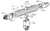
도10은 T자형 소스 전력 케이블 섹션의 등각도이다.10 is an isometric view of a T-shaped source power cable section.

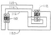
도11은 도10의 T자형 소스 전력 케이블 섹션의 개략적인 회로도이다.11 is a schematic circuit diagram of the T-shaped source power cable section of FIG.

도12는 직선형 단말 소스 전력 케이블 섹션의 등각도이다.12 is an isometric view of a straight terminal source power cable section.

도13은 도12의 직선형 단말 소스 전력 케이블 섹션의 개략적인 회로도이다.Figure 13 is a schematic circuit diagram of the straight terminal source power cable section of Figure 12;

도14는 예시적인 슬레이브 어댑터 케이블의 등각도이다.14 is an isometric view of an exemplary slave adapter cable.

도15는 도14의 슬레이브 어댑터 케이블의 개략적인 회로도이다.Figure 15 is a schematic circuit diagram of the slave adapter cable of Figure 14;

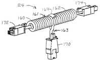
도16은 T자형 슬레이브 제어 전력 케이블 섹션의 등각도이다.16 is an isometric view of a T-shaped slave control power cable section.

도17은 도16의 T자형 슬레이브 제어 전력 케이블 섹션의 개략적인 회로도이다.17 is a schematic circuit diagram of the T-shaped slave control power cable section of Fig.

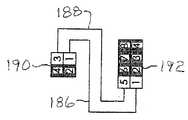
도18은 직선형 단말 슬레이브 제어 전력 케이블 섹션의 등각도이다.18 is an isometric view of a straight line terminal slave control power cable section.

도19는 도18의 직선형 단말 슬레이브 제어 전력 케이블의 개략적인 회로도이다.19 is a schematic circuit diagram of the linear terminal slave control power cable of Fig. 18;

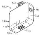
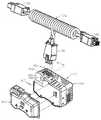
도20은 히터 제어기에 추가의 기능성을 제공하기 위해 베이스 모듈 상에 향상된 제어 확장 모듈이 설치된 예시적인 기초 히터 제어기의 등각도이다.20 is an isometric view of an exemplary base heater controller in which an enhanced control expansion module is installed on the base module to provide additional functionality to the heater controller.

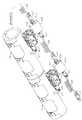
도21은 히터 제어기의 베이스 모듈 상에 설치되도록 취해진 위치에 향상된 제어 확장 모듈을 갖는 기초 히터 제어기의 등각도이다.21 is an isometric view of the basic heater controller with an enhanced control expansion module in a position taken to be installed on the base module of the heater controller.

도22는 예시적인 확장 모듈 접촉 패드 및 투광성 보스 구성요소를 도시하기 위해 상이한 시점에서 본 향상된 제어 확장 모듈의 등각도로서, 이들 특징부를 보다 잘 나타내기 위해 확대된 도면이다.22 is an enlarged view for better illustrating these features as an isometric view of an enhanced control expansion module seen at different times to illustrate an exemplary expansion module contact pad and a translucent boss component.

도23은 히터 제어기 베이스 모듈 상에 설치되도록 취해진 위치에 대체용 먼지 커버를 갖는 기초 히터 제어기의 등각도이다.Figure 23 is an isometric view of a basic heater controller having a replacement dust cover in a position taken to be installed on the heater controller base module.

도24는 모듈 장착 장치를 도시하기 위해 상이한 시점에서 본 히터 제어기 베이스 모듈의 등각도이다.24 is an isometric view of the heater controller base module viewed at different times to illustrate the module mounting apparatus.

도25는 도24와 유사한 히터 제어기 베이스 모듈의 등각도로서, 장착 장치가 히터 제어기에의 접속을 위해 취해진 위치에 있는 도면이다.25 is an isometric view of a heater controller base module similar to that of FIG. 24, with the mounting device in the position taken for connection to the heater controller;

도26은 도24 및 도25의 장착 장치의 등각도로서, 작동 부착 구성요소를 도시하기 위해 상이한 시점에서 본 도면이다.Fig. 26 is an isometric view of the mounting device of Figs. 24 and 25, taken at different viewpoints to illustrate the actuation attachment components; Fig.

도27은 AC 전원 및 예를 들어 원격 모니터링 스테이션에 위치한 경보/알람 신호 회로에 접속된 예시적인 다수의 개별 히터 제어 구성의 개략적인 회로도이다.27 is a schematic circuit diagram of an exemplary plurality of individual heater control configurations connected to an AC power source and, for example, an alarm / alarm signal circuit located at a remote monitoring station.

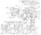
도28은 예시적인 단일 포인트 제어 구성에 있어서의 슬레이브 어댑터 케이 블, T자형 슬레이브 히터 케이블 및 단말 슬레이브 제어 전력 케이블을 거쳐 다수의 파이프 히터 및 T자형 소스 전력 케이블에 접속된 개선된 제어 확장 모듈 및 히터 제어기 베이스 유닛의 개략적인 회로도이다.Figure 28 shows an improved control expansion module and heater connected to a plurality of pipe heaters and T-shaped source power cables via a slave adapter cable, a T-shaped slave heater cable and a terminal slave control power cable in an exemplary single point control configuration Figure 2 is a schematic circuit diagram of a controller base unit.

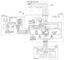
도29는 도28과 유사한 개략적인 회로도로서, 제어기가 단말 소스 전력 케이블 섹션에 접속된 상태를 도시한다.Fig. 29 is a schematic circuit diagram similar to Fig. 28, in which the controller is connected to the terminal source power cable section. Fig.

도30은 히터 제어기 베이스의 개략적인 회로도로서, 개선된 제어 확장 모듈, T자형 소스 전력 케이블 및 파이프 히터 구성요소가 도1 내지 도4에 도시된 것들과 같은 다수의 국지 제어 구성을 위해 또는 단일 파이프 히터를 위해 행하여질 수 있는 바와 같이 히터 제어기 베이스 유닛에 직접 접속된 상태를 도시한다.Figure 30 is a schematic circuit diagram of a heater controller base in which an improved control extension module, a T-shaped source power cable, and a pipe heater component are provided for a number of local control configurations, such as those shown in Figures 1-4, And directly connected to the heater controller base unit as can be done for the heater.

도31은 도30과 유사한 개략적인 회로도로서, 히터가 단일 히터이거나 마지막 히터가 다수 개별 제어 히터의 시리즈 내에서 제어되는 개별 히터 제어 장치를 도시하기 위해 고전압 전력 및 저전압 단일 회로가 단말처리된 제어 전력 케이블에 의해 제어기에 직접 접속된 상태를 도시한다.Fig. 31 is a schematic circuit diagram similar to Fig. 30, in which a high-voltage power and a low-voltage single circuit are connected to a terminal-controlled control electric power source, in order to illustrate a separate heater control device in which the heater is a single heater or the last heater is controlled in a series of a plurality of individual control heaters And is directly connected to the controller by a cable.

도32는 히터 제어기를 위한 예시적인 로직를 도시하는 로직 흐름도다.32 is a logic flow diagram illustrating exemplary logic for a heater controller.

도33은 도30과 유사한 개별 히터 제어 장치의 개략적인 회로도로서, PTC 서미스터 온도 센서를 가진 예시적인 상한 제어 회로를 도시한다.FIG. 33 is a schematic circuit diagram of an individual heater control device similar to FIG. 30, illustrating an exemplary upper limit control circuit with a PTC thermistor temperature sensor.

도34는 도33과 유사한 개략적인 회로도로서, PTC 서미스터 온도 센서를 가진 예시적인 상한 제어 회로를 도시한다.34 is a schematic circuit diagram similar to FIG. 33, showing an exemplary upper limit control circuit with a PTC thermistor temperature sensor.

도35는 슬레이브 어댑터 접속 배선함의 등각도이다.35 is an isometric view of the slave adapter connection wiring box.

도36은 도35의 슬레이브 어댑터 접속 배선함의 등각도로서, 상이한 시점에서 바라본 도면이다.Fig. 36 is an isometric view of the slave adapter connection wiring box shown in Fig. 35, and is a view seen from a different viewpoint.

도37은 도35 및 도36의 슬레이브 어댑터 접속 배선함의 개략적인 회로도이다.37 is a schematic circuit diagram of the slave adapter connection wiring box of Figs. 35 and 36. Fig.

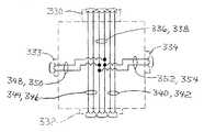
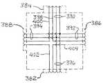
도38은 도28과 유사한 개략적인 회로도로서, 도35 내지 도37의 슬레이브 어댑터 접속 배선함이 도28에 도시된 슬레이브 어댑터 케이블을 대체한 것을 도시한다.Fig. 38 is a schematic circuit diagram similar to Fig. 28, in which the slave adapter connection wiring box of Figs. 35 to 37 replaces the slave adapter cable shown in Fig.

도39는 예시적인 소스 전력 접속 배선함의 등각도이다.39 is an isometric view of an exemplary source power connection junction box.

도40은 도39의 예시적인 소스 전력 접속 배선함의 등각도로서, 상이한 시점에서 바라본 도면이다.40 is an isometric view of the exemplary source power connection junction box of FIG. 39, and is a view at different viewpoints.

도41은 도39 및 도40의 소스 전력 접속 배선함의 개략적인 회로도이다.41 is a schematic circuit diagram of the source power connection wiring box of Figs. 39 and 40. Fig.

도42는 도39 및 도40의 복수의 전원 접속 배선함과 데이지 체인 접속된 복수의 히터 제어기의 등각도이다.42 is an isometric view of a plurality of heater controllers daisy-chained with the plurality of power connection junction boxes of Figs. 39 and 40. Fig.

도43은 다수의 트렁크 출구 커넥터를 가진 소스 전력 접속 배선함의 다른 변형예의 등각도이다.Figure 43 is an isometric view of another variant of a source power interconnect box with a plurality of trunk exit connectors.

도44는 도43의 소스 전력 접속 배선함의 등각도로서, 상이한 시점에서 바라본 도면이다.Fig. 44 is an isometric view of the source power connection wiring box of Fig. 43, and is a view at different viewpoints.

도45는 도43 및 도44의 소스 전력 접속 배선함의 개략적인 회로도이다.45 is a schematic circuit diagram of the source power connection wiring box of Figs. 43 and 44. Fig.

도46은 제어기 베이스 모듈 및 확장 모듈의 등각도로서, 탄성 스프링 바이어스 탭을 포함하는 커넥터 리테이너 특징부를 도시하기 위해 T자형 소스 전력 케이블의 브랜치 출구 커텍터가 제어기의 입구 커넥터에 삽입되도록 위치된 상태의 도 면이다.46 is an isometric view of the controller base module and the extension module, in which the branch outlet connector of the T-shaped source power cable is positioned to be inserted into the controller's inlet connector to show the connector retainer feature including the resilient spring bias tab It is a map.

도47은 브랜치 출구 커넥터 및 제어기 입구 커넥터를 위한 랫치 및 탄성 스프링 바이어스 탭의 단면도로서, 브랜치 출구 커넥터가 제어기 입구 커넥터 내로 플러그된 상태의 도면이다.47 is a cross-sectional view of the latch and elastic spring bias tabs for the branch outlet connector and the controller inlet connector, with the branch outlet connector plugged into the controller inlet connector;

도48은 도47과 유사한 단면도로서, 랫치의 해제를 위해 탄성 스프링 바이어스 탭의 바이어스력에 맞서 피봇되는 랫치 레버를 도시한다.Figure 48 is a cross-sectional view similar to that of Figure 47, showing the latch lever pivoted against the biasing force of the resilient spring bias tab for release of the latch.

도49는 도47과 유사한 단면도로서, 고정 바이어스력을 제공하기 위한 리프 스프링을 도시한다.Figure 49 is a cross-sectional view similar to Figure 47, showing a leaf spring for providing a fixed biasing force;

도50은 도47과 유사한 단면도로서, 고정 바이어스력을 제공하기 위한 코일형 압축 스프링을 도시한다.Figure 50 is a cross-sectional view similar to Figure 47, showing a coiled compression spring for providing a fixed bias force.

도51은 도47과 유사한 단면도로서, 고정 바이어스력을 제공하기 위한 탄성 압축성 재료를 도시한다.51 is a cross-sectional view similar to that of FIG. 47 showing an elastomeric compressible material for providing a fixed bias force.

도1 및 도5에 포괄적으로 도시된 다수 히터 제어 시스템(10)은, 시스템의 다양한 구성요소들 및 구성요소들의 조합이 다양한 히터 모니터링 및 제어 구성 요건을 만족시키기 위해 다양한 방법으로 조립 및 접속되도록, 예시적인 구성요소들에 의해 촉진된 융통성 및 확장된 모듈성에 기초한다. 시스템(10)은 예를 들어 도1에 도시된 개별 국지 히터 제어 구성(12) 및 예를 들어 도5에 도시된 구역 또는 군집 구성(14) 내의 다수의 히터를 위한 단일 포인트 제어 구성인 2개의 기초 구성과 관련하여 가장 잘 설명된다. 이들 기초 히터 제어 시스템 구성(12, 14)의 다른 조합 및 변형은 시스템(10)의 주요 구성요소 중 선택된 하나 또는 모두에 의해 생성될 수 있으며, 이는 예시적인 실시예 및 구성요소들의 설명이 계속됨에 따라 당업자들에게 명백할 것이다.The multipleheater control system 10, shown generally in Figures 1 and 5, is designed to enable various components and components of the system to be assembled and connected in a variety of ways to meet various heater monitoring and control configuration requirements, Based on the flexibility and extended modularity facilitated by the exemplary components. Thesystem 10 may be implemented, for example, in the individual localheater control arrangement 12 shown in FIG. 1 and in the single zone control arrangement for multiple heaters in the zone orcluster arrangement 14 shown in FIG. 5, It is best explained in relation to the basic composition. Other combinations and variations of these basic heatercontrol system configurations 12, 14 can be created by one or all of the major components of thesystem 10, which is a continuation of the description of exemplary embodiments and components Will be apparent to those skilled in the art.

다수 히터 제어 시스템(10)은 도1 및 도5에 도시된 바와 같이 주로 파이프 히터(16)를 위해 설계되지만, 다른 종류의 히터를 위해서 사용될 수도 있다. 따라서, 편의를 위해, 본 설명은 다른 종류의 히터에도 적용할 수 있다는 이해를 갖고 다수 파이프 히터(16)의 환경에서 진행될 것이다.The multipleheater control system 10 is designed primarily for thepipe heater 16 as shown in Figures 1 and 5, but may also be used for other types of heaters. Thus, for the sake of convenience, the present description will proceed in the context of a multiple-pipe heater 16 with the understanding that it can also be applied to other types of heaters.

개별 국지 히터 제어 구성(12)에 대한 도1을 주로 참조하면, 복수의 파이프 히터(16)가 도시되어 있다. 이들은 일반적으로 이하에 보다 상세히 설명되는 바와 같이 파이프(도1 내지 도4에는 도시되어 있지 않고 도9에 도시됨) 상에 장착되도록 배열 및 정렬된다. 이 실시예에서는, 각각의 히터(16)에 대해 별도의 제어기(20)가 존재한다. 따라서, 도1 내지 도4에 도시된 바와 같이, 각각의 제어기(20)는, 고전압 AC 라인(소스) 전력을 히터(16) 내의 히터 요소(32)(도9)에 전달하고 제어할 뿐만 아니라 제어기(20)가 접속된 각각의 히터(16) 내의 온도 센서(50, 52)(도9)로부터 온도 정보를 도출하는 방식으로, 각각의 히터(16)에 직접 접속된다. 따라서, 각각의 제어기(20)는 그것이 접속된 개별 히터(16) 내의 온도 센서(50, 52)에 응답하여, 후술하는 바와 같이 제어기(20)의 설정에 따라 히터(16)로의 고전압 전력을 온/오프시킨다. 따라서, 제어기(20)에 의해 히터(16)에 전달되는 고전압 AC 전력은 종종 본원에서 "제어된 AC 전력"으로 불리며, AC 전원으로부터 제어기에 의해 수용된 고전압 AC 전력은 종종 본원에서 "소스 AC 전력" 또는 "AC 소스 전력" 또는 단순히 "소스 전력"으로 지칭된다. 본원에서 "고전압"이라는 용어는 30볼트보다 위의 임의의 값을 의미한다. 예를 들어, 일반적인 히터는 종종 정상의 110-120볼트, 220-240볼트, 440-480볼트 또는 특정 설비의 열 생산 요건에 부합하기에 충분한 전력을 제공하는 다른 전압에 의해 전력을 제공받는다. AC는 교류 전류를 의미하며, 50헤르쯔, 60헤르쯔 또는 히터 내의 가열 요소에 전력을 제공하는데 사용되는 임의의 다른 교류 전류 주파수일 수 있다.Referring primarily to Figure 1 for an individual localheater control arrangement 12, a plurality ofpipe heaters 16 are shown. These are generally arranged and aligned to be mounted on a pipe (not shown in Figs. 1 to 4 and shown in Fig. 9) as will be described in more detail below. In this embodiment, there is aseparate controller 20 for eachheater 16. Thus, as shown in Figures 1-4, eachcontroller 20 not only communicates and controls the high voltage AC line (source) power to the heater element 32 (Figure 9) in theheater 16 Thecontroller 20 is directly connected to eachheater 16 in such a manner as to derive temperature information from thetemperature sensors 50 and 52 (Fig. 9) in therespective heaters 16 to which they are connected. Eachcontroller 20 thus responds to thetemperature sensors 50 and 52 in theindividual heater 16 to which it is connected and turns on the high voltage power to theheater 16 according to the setting of thecontroller 20, / Turn off. Thus, the high voltage AC power delivered to theheater 16 by thecontroller 20 is often referred to herein as the "controlled AC power ", and the high voltage AC power received by the controller from the AC power supply is often referred to herein as the" source AC power " Or "AC source power" or simply "source power ". The term "high voltage" as used herein means any value above 30 volts. For example, generic heaters are often powered by 110-120 volts of normal, 220-240 volts, 440-480 volts, or other voltages that provide enough power to meet the thermal production requirements of a particular facility. AC means alternating current and may be 50 Hz, 60 Hz or any other alternating current frequency used to provide power to heating elements within the heater.

개별 국지 히터 제어 구성(12) 내의 복수의 제어기(20)는 고전압 AC 전력 소스(13)(도27)에 데이지 체인 접속되며, 고전압 AC 전원(13)은 T자형 소스 전력/신호 케이블(26)에 의해 원격 모니터 및/또는 제어 장치(15)(도27)와 결합될 수 있으며, T자형 소스 전력/신호 케이블(26)은 제어기(20)에 소스 AC 전력을 전달하기 위한 고전압 전력 라인 및 저전압 신호 라인을 모두 수납하고, 저전압 신호 라인은 임의의 목적으로 사용될 수 있는 이하에 상세히 설명된 저전압 온도 범위 경보 신호를 포함한다. 본 설명에서 "저전압"이라는 용어는 30볼트를 초과하지 않는 임의의 전압을 의미한다. 또한, 도1 및 도4에 표시된 바와 같이, 임의의 수의 추가 히터(16) 및 제어기(20) 조립체가 추가의 T자형 소스 전력/신호 케이블(26)에 의해, 그리고 데이지 체인 내의 최종 제어기(20)에 접속된 직선형 전력/신호 케이블(108)(도2)(도1 내지 도4에 도시되어 있지 않으나, 이하에 설명됨)을 이용하여 서로 데이지 체인 접속될 수 있다.The plurality ofcontrollers 20 in the individual localizedheater control configuration 12 are daisy-chained to a high voltage AC power source 13 (Figure 27) and a high voltageAC power source 13 is connected to the T- 27), and the T-shaped source power /signal cable 26 may be coupled to a high voltage power line and a low voltage power line (not shown) to deliver source AC power to thecontroller 20, Signal line, and the low voltage signal line includes the low voltage temperature range alarm signal, which is described in detail below, which can be used for any purpose. The term "low voltage" in this description refers to any voltage not exceeding 30 volts. 1 and 4, any number ofadditional heaters 16 andcontroller 20 assemblies may be connected by additional T-shaped source power /signal cable 26 and by a final controller (not shown) within the daisy chain Signal cable 108 (Fig. 2) (not shown in Figs. 1 to 4, but described below) connected to the power /

또한, 개별 제어 히터(16) 및 슬레이브 히터(16')의 임의의 조합이 수용될 수 있다. 예를 들어, 도5 내지 도8에 도시된 바와 같이, 추가의 개별 제어 히 터(16) 및/또는 슬레이브 히터(16')의 추가의 단일 포인트 제어 구역이 T자형 소스 전력 케이블(26)에 접속될 수 있다.In addition, any combination of theindividual control heater 16 and the slave heater 16 'can be accommodated. 5 to 8, additional single point control zones of additionalindividual control heater 16 and / or slave heater 16 'may be connected to T-shapedsource power cable 26 Can be connected.

예시적인 실시예 및 구현예에 대한 보다 상세한 설명을 위해, 제한을 위해서가 아니라 이해를 돕기 위해 예시적인 히터의 온도 센서 및 히터 요소를 참조하는 것이 도움이 된다. 일반적으로, 이 시스템들에 의해 제어될 수 있는 히터의 많은 변형, 재료 및 구조가 존재한다. 따라서, 본 발명은 임의의 특정 히터 또는 히터 구조체에 한정되지 않는다. 그러나, 설명을 용이하게 하기 위해, 파이프(P)에 장착된 예시적인 파이프 히터(16)가 도9에 단면도로 도시되어 있다. 이 파이프 히터(16)는 참조로 본원에 합체된 미국 특허 제5,714,738호 및 제6,894,254호에 설명된 것들과 많은 유사성을 갖지만, 이하에 설명되는 몇 가지 상이한 또는 추가의 특징들이 존재한다.For a more detailed description of exemplary embodiments and implementations, it is helpful to refer to the exemplary heater temperature sensor and heater element for ease of understanding and not for purposes of limitation. In general, there are many variations, materials, and structures of the heaters that can be controlled by these systems. Accordingly, the present invention is not limited to any particular heater or heater structure. However, for ease of explanation, anexemplary pipe heater 16 mounted on a pipe P is shown in cross-sectional view in Fig. Thepipe heater 16 has many similarities with those described in U.S. Patent Nos. 5,714,738 and 6,894,254, incorporated herein by reference, but there are several different or additional features described below.

간략히, 도9의 예시적인 파이프 히터(16)는 저항성 와이어 또는 기타 저항성 발열 재료가 매설된 가열 요소(32)를 가진 고밀도 실리콘 고무 히터 매트(30)를 포함한다. 가열 요소(32)는 대개 110-120볼트, 220-240볼트, 또는 특정 응용예에 필요한 열을 발생시키는데 충분한 전력을 제공하는 임의의 다른 전압 레벨과 같은 표준 고전압 레벨에서 그것을 통해 전류가 흐를 때 열을 발생시킨다. 히터 매트(30)는 저밀도 폐쇄 셀 실리콘 고무 발포체 또는 임의의 다른 적절한 단열 재료로 이루어진 단열 히터 재킷(34)으로 둘러싸인다. 스트랩(38)(도1 내지 도8)을 가진 체결 고삐(36)가 파이프(P) 또는 가열되어야 할 다른 구성요소 상의 제 위치에 히터(16)를 고정하기 위해 제공될 수 있다.Briefly, theexemplary pipe heater 16 of FIG. 9 includes a high density siliconerubber heater mat 30 having aheating element 32 with a resistive wire or other resistive heating material embedded therein. Theheating element 32 is typically at a standard high voltage level, such as 110-120 volts, 220-240 volts, or any other voltage level that provides enough power to generate the heat required for a particular application, . Theheater mat 30 is surrounded by an insulatingheater jacket 34 made of a low density closed cell silicone rubber foam or any other suitable heat insulating material. Afastening reins 36 with straps 38 (Figures 1-8) may be provided to secure theheater 16 in place on the pipe P or other component to be heated.

히터(16)는 캐비티(40)를 가지며, 여기에서 고전압 전력 라인(42, 44)이 가열 요소(32)로부터의 리드(46, 48)에 접속된다. 서모커플, 서미스터 또는 임의의 다른 적절한 온도 감지 장치와 같은 온도 센서(50, 52)가 히터 매트(30)에 인접하여 발포체 단열 재킷(34)에 매설되고, 그리하여 히터 매트(30)에서 또는 그 히터 매트(30) 근처에서 온도를 검출할 수 있다. 예를 들어 온도 센서(52)와 같은 온도 센서들 중 하나로부터의 신호는 정상적인 동작 또는 처리 히터 제어 기능성을 위해 제어기(20)에 의해 사용되며, 예를 들어 온도 센서(50)와 같은 다른 온도 센서로부터의 신호는 이하에 상세히 설명되는 바와 같이 온도 상한 제어를 위해 제어기(20)에 의해 사용된다. 이들 기능 모두를 위해 하나의 온도 센서가 사용될 수 있지만, 특히 고온 제한 기능을 위해 2개의 온도 센서 중복성을 제공하는 것이 더 좋다. 고온 제한 기능은 제어기 내의 처리 제어 회로 및/또는 처리 온도 센서가 고장나서 탈출 히터 상황을 초래하는 경우에 히터를 꺼야한다. 몇몇 안전 인증 기관들은 안정 인증을 위해 그러한 중복성을 요구한다.Heater 16 has acavity 40 in which highvoltage power lines 42 and 44 are connected to leads 46 and 48 fromheating element 32. Atemperature sensor 50 or 52 such as a thermocouple, thermistor or any other suitable temperature sensing device is embedded in thefoam insulation jacket 34 adjacent to theheater mat 30, The temperature can be detected in the vicinity of themat 30. Signals from one of the temperature sensors, such as, for example, thetemperature sensor 52, are used by thecontroller 20 for normal operation or process heater control functionality and may be used by other temperature sensors, Is used by thecontroller 20 for temperature upper limit control as described in detail below. Although one temperature sensor can be used for both of these functions, it is better to provide two temperature sensor redundancies, especially for high temperature limiting functions. The high temperature limit function should turn the heater off if the process control circuitry in the controller and / or the process temperature sensor fails and results in an escape heater situation. Some safety certification authorities require such redundancy for stable authentication.

제1 ("상한") 온도 센서(50)를 위한 저전압 와이어(54, 56) 및 제2 ("처리") 온도 센서(52)를 위한 저전압 와이어(58, 60)는 캐비티(40) 및 가요성 코드(62)를 통해 예를 들어 Molex(등록상표) 커넥터와 같은 케이블 커넥터(64)로 향한다. 부트(boot)(66)가 가요성 코드(62)를 파이프 히터(16)에 고정하고 캐비티(40)를 덮는다. 히터 코드(62)는 임의의 원하는 길이일 수 있다. 몇몇 실시예에서, 코드(62)는 특히 고온 응용예에서 제어기(20)의 열 손상을 방지하기 위해 제어기(20)(도1 내지 도8) 및 커넥터(64)를 히터(16)로부터 충분히 멀리 배치할 만큼 충분한 길이 를 갖는다. 물론, 도1 내지 도8에 도시된 바와 같이, 제어기(20)는 커넥터(64)를 통해 개별 히터 제어 구성(14)을 위한 도1 내지 도4에 도시된 바와 같이 직접 또는 이하에 더욱 상세히 설명되는 바와 같이 슬레이브 어댑터(22) 및 슬레이브 히터 케이블[24(도1) 및 184(도18)]을 거쳐 파이프 히터(16)에 접속된다.Thelow voltage wires 54,56 for the first ("high")temperature sensor 50 and thelow voltage wires 58,60 for the second ("processing")temperature sensor 52 are connected to thecavity 40, Such as a Molex < (R) > connector. ≪ / RTI > A boot 66 secures theflexible cord 62 to thepipe heater 16 and covers thecavity 40. Theheater cord 62 may be of any desired length. In some embodiments, thecord 62 may be located far enough away from theheater 16 to secure the controller 20 (Figs. 1-8) and theconnector 64 to prevent thermal damage to thecontroller 20, Has a sufficient length to be placed. Of course, as shown in Figures 1-8, thecontroller 20 may be directly or via aconnector 64, as shown in Figures 1-4 for an individualheater control configuration 14, Is connected to thepipe heater 16 via theslave adapter 22 and the slave heater cables 24 (Fig. 1) and 184 (Fig. 18) as shown.

다수 히터 제어 시스템의 개별 구성 부품들의 구조적 상세를 더 설명하기 전에, 도27을 참조하며, 이것은 도1 및 도9와 함께 전기 구성요소들 중 몇몇의 개요와 시스템의 기능들을 제공하며, 이하에 설명되는 다른 구성요소 및 특징의 이해에 도움이 된다. 따라서, 도27을 참조하고 2차적으로 도1 및 도9을 참조하면, 복수의 제어기(20)들은 주로 그러나 비배타적으로 특정한 원하는 온도 범위 내에서 히터(16)가 작동하는 것을 유지하기 위해 히터(16)에 제어된 AC 전력을 제공하도록 각각의 히터(16)에 개별적으로 접속될 수 있다.Before further describing the structural details of the individual components of the multiple heater control system, reference is made to Fig. 27, which, together with Figs. 1 and 9, provides an overview of some of the electrical components and the functions of the system, The present invention is helpful in understanding other components and features of the present invention. Thus, referring to Figure 27 and secondarily to Figures 1 and 9, a plurality ofcontrollers 20 are operatively connected to a heater (not shown) to maintain theheater 16 operating within a particular desired temperature range, 16 to each of theheaters 16 to provide controlled AC power.

데이지 체인 방식으로 서로 접속된 케이블 섹션(25, 26, 108)의 데이지 체인 접속 시리즈는 제어기(20)에 AC 소스 전력을 전달하는 소스 전력 트렁크 라인을 형성한다. 제어기(20)는 원하는 온도를 유지하기 위해 필요한 열을 발생시키기 위해 히터(16)가 필요로 하는 만큼 히터(16)에 제어된 AC 전력을 전달하도록 AC 전력을 온/오프시킨다. 제어기(20)는 방전 및 발열을 최소화하기 위해 기계식 릴레이(305)와 병렬인, 트라이액(303)과 같은 고체 상태 스위치일 수 있거나 또는 제어된 AC 전력을 발생시키도록 제어가능한 임의의 스위치일 수 있는 처리 전력 스위치 구성(302)에 의해 AC 전력을 온/오프시킨다. 제어된 AC 전력을 상승 또는 하강 조절하기 위해 배리액(variac) 변압기(도시되지 않음)와 같은 가변 전력 제어를 사용 하는 것이 또한 가능하지만, 이들은 스위치 장치보다 훨씬 크고 거대하며 비싸다. 히터(16) 내의 제2 (처리) 온도 센서(52)로부터의 온도 신호 피드백을 사용한 처리 전력 스위치 구성(302)의 제어가 이하에서 더욱 상세히 설명된다.The daisy chained series ofcable sections 25, 26 and 108 connected together in a daisy chain form a source power trunk line carrying AC source power to thecontroller 20. Thecontroller 20 turns on / off the AC power to deliver the controlled AC power to theheater 16 as much as theheater 16 needs to generate the heat necessary to maintain the desired temperature.Controller 20 may be a solid state switch, such astriac 303, in parallel withmechanical relay 305 to minimize discharge and heat generation, or may be any switch controllable to generate controlled AC power The AC power is turned on / off by the processingpower switch configuration 302 of FIG. It is also possible to use variable power control, such as a variac transformer (not shown), to raise or lower the controlled AC power, but they are much larger, larger, and more expensive than switch devices. Control of the processingpower switch configuration 302 using temperature signal feedback from the second (processing)temperature sensor 52 in theheater 16 is described in further detail below.

히터(16)의 온도가 제1 (상한) 온도 센서(50)에 의해 감지된 안전하지 못한 레벨까지 상승하는 경우에 히터(16)로의 AC 전력을 차단하기 위해 고온 제한 스위치(상한 스위치로도 불림)(300)가 또한 제공된다. 그러한 안전하지 못한 온도 레벨은 처리 파워 스위치(302), 처리 온도 센서(52), 또는 처리 제어 회로(296)(도28)의 기능 불량으로 인한 것일 수 있거나, 또는 파이프 내의 고온 정화 또는 세척과 같은 몇몇 외부 요인 또는 임의의 다른 요인으로 인한 것일 수 있다. 조작자의 개입 동안 AC 전력이 일단 오프되면 AC 전력을 오프 상태로 유지하기 위해 래칭 기능을 포함하는, 온도 피드백 또는 온도 센서(50)로부터의 입력을 사용한 상한 스위치(300)의 제어가 이하에서 더욱 상세히 설명된다.A high temperature limit switch (also referred to as an upper limit switch) is provided to cut off the AC power to theheater 16 when the temperature of theheater 16 rises to an unsafe level sensed by the first (upper) ) 300 are also provided. Such an insecure temperature level may be due to a malfunction of theprocess power switch 302, theprocess temperature sensor 52, or the process control circuit 296 (Figure 28) Some external factors or some other factor. The control of theupper limit switch 300 using the temperature feedback or the input from thetemperature sensor 50, which includes a latching function to keep the AC power in the off state once the AC power is off during the operator ' s intervention, .

경보/알람 기능이 또한 제공되며, 이것은 데이지 체인 접속 시리즈 내의 제어기(20)들 중 어느 하나가 그것에 의해 제어되는 히터(16)가 요구 또는 필요 작동 온도 범위보다 위 또는 아래의 온도에 있음을 검출하였을 때 원격 모니터 스테이션(15)에서 경보/알람을 발신한다. 예를 들어, 화학적 처리, 이송 또는 진행될 다른 행위를 위한 특정 온도 범위 내에 파이프(P)(도9)를 유지할 필요가 있다면, 이 경보/알람 기능(17)은 제어기(20) 중 어느 것이 그러한 온도 범위 밖의 히터(16) 온도를 검출했는지를 원격 모니터 스테이션(15)에서 조작자에게 알려주고, 그리고/또는 당업자가 이해할 수 있는 바와 같이 히터(16)들이 모두 원하는 범위의 온도를 발생시킬 때까지 장비의 작동 또는 차단을 방지하기 위해 장비 인터록(19)에 대해 신호를 발생시킬 수 있다. 도27에 블록으로 한정된 모니터 스테이션(15)은 개략적으로만 도시되어 있다. 예를 들어 DC 전력 공급원(21), 연속성 검출기(31), 신호 회로(23), 및 경보/알람(17)과 같은 다양한 구성요소 및 기능들은 하나의 위치 또는 다이버 위치에 있을 수 있고, 따라서 본 설명에서 "원격 모니터 스테이션"이라는 용어의 사용은 편의를 위한 것일 뿐이며, 설명되거나 도시된 구성요소 또는 기능들이 하나의 위치 또는 단일 구성 또는 조립체 내에 함께 있는 것으로 제한하지 않는다.An alarm / alarm function is also provided, which indicates that any one of thecontrollers 20 in the daisy chain connection series has detected that theheater 16 controlled by it is at a temperature above or below the required or required operating temperature range Alarm / alarm is issued at the remote monitor station (15). For example, if it is necessary to keep the pipe P (Fig. 9) within a certain temperature range for chemical treatment, transfer or other action to be taken, the alarm / It is necessary to inform the operator at theremote monitoring station 15 whether theheater 16 temperature outside the range has been detected and / or to operate the equipment until theheaters 16 all produce the desired range of temperatures, as will be understood by those skilled in the art Or to generate a signal for theequipment interlock 19 to prevent blocking. Themonitor station 15, which is limited to blocks in Fig. 27, is shown only schematically. Various components and functions such as, for example,DC power supply 21,continuity detector 31,signal circuit 23, and alarm /alarm 17 may be in one position or diver position, The use of the term "remote monitor station" in the description is for convenience only and does not limit the described or illustrated components or functions to being in one location or a single configuration or assembly.

이 경보/알람 기능(온도 범위 신호로 지칭하기도 함)을 실시하기 위해, 원격 모니터링 스테이션(15)에 있는 저전압 DC 전력 공급원(21)이 데이지 체인 케이블 섹션(25, 26, 108)을 거쳐 모든 제어기(26)로 진행하는 한 쌍의 전도체(27, 29)를 포함하는 신호 회로(23) 상에 저전압 DC 전위를 제공한다. 본원에서 저전압은 대체로 30볼트를 넘지 않는 것으로 간주된다. 따라서, 고전압은 30볼트를 넘는 임의의 값이다. 전도체 중 하나, 예를 들어 전도체(29)는 각각의 제어기(20)를 통해 연장되며, 여기에서 릴레이 스위치(310)의 대향 단자에 직렬로 접속된다. 따라서, 제어기(20)들 중 어느 하나 내의 직렬 접속 릴레이 스위치(310)들 중 어느 하나가 회로(23)를 개방할 수 있다. 즉, 신호 회로(23)에 전류가 흐르는 것을 막을 수 있다. 반대로, 신호 회로(23)가 폐쇄되도록 하기 위해서는 모든 제어기(20) 내의 모든 릴레이 스위치(310)가 폐쇄되어야 한다. 본원에 사용되는 "릴레이 스위치"라는 용어는 스위치를 개방 및/또는 폐쇄하기 위해, 즉 스위치를 통해 전류가 흐르는 것 을 차단 및/또는 허용하기 위해 제어 신호 입력이 적용될 수 있는 임의의 스위치, 기계 또는 고체 상태를 의미할 수 있다.The low voltageDC power supply 21 in theremote monitoring station 15 is connected via daisy-chainedcable sections 25, 26 and 108 to all of the controllers (not shown) to perform this alarm / alarm function Voltage DC potential on asignal circuit 23 comprising a pair ofconductors 27, Herein, the undervoltage is generally considered not to exceed 30 volts. Hence, the high voltage is an arbitrary value exceeding 30 volts. One of the conductors, for example aconductor 29, extends through eachcontroller 20, where it is connected in series to the opposite terminal of therelay switch 310. Thus, any one of the series-connected relay switches 310 in any one of thecontrollers 20 can open thecircuit 23. [ That is, it is possible to prevent a current from flowing to thesignal circuit 23. [ Conversely, in order to close thesignal circuit 23, all the relay switches 310 in all thecontrollers 20 must be closed. As used herein, the term "relay switch" refers to any switch, machine or device that can be used to open and / or close a switch, i.e., to block and / or allow current to flow through the switch, It can mean a solid state.

원격 모니터링 스테이션(15)과 결합된 연속성 검출기(31)는 신호 회로(23)가 개방 또는 폐쇄되었는지를 검출한다. 릴레이 스위치(310)들 중 어느 하나가 개방됨으로써 또는 데이지 체인 케이블(25, 26, 108) 내의 임의의 단절 또는 끊어짐에 의해 유발될 수 있는 신호 회로의 개방이 검출되면, 연속성 검출기(31)가 경보/알람(17) 및/또는 장비 인터록(19) 또는 조작자가 원한다면 임의의 다른 장치 또는 기능에 대해 신호를 발생한다. 다시 말해, 연속성 검출기(31)는 경보 또는 알람을 개시하는데 사용될 수 있거나 또는 당업자가 본 설명을 읽고 알 수 있는 바와 같이 사용중인 장비를 정지시키는데 사용될 수 있다. 전류 검출기 회로, 전압 검출기 회로 등과 같은, 이러한 기능을 수행할 수 있는 다양한 연속성 검출기는 용이하게 구입가능하며, 당업자에게 잘 알려져 있거나 당업자에 의해 용이하게 구성될 수 있고, 따라서 이러한 특징부에 대한 이해를 위해 더 이상의 설명이 요구되지는 않는다. 편의를 위해, 그러나 제한을 목적으로 하지 않고, 신호 회로(23)는 "경보/알람 신호 회로" 또는 "온도 범위 신호 회로"로 지칭되기도 하지만, 신호는 장치 인터록 및 다른 목적으로도 사용될 수 있다.Thecontinuity detector 31 coupled with theremote monitoring station 15 detects whether thesignal circuit 23 is open or closed. When either of the relay switches 310 is opened or the opening of the signal circuit which may be caused by any disconnection or break in thedaisy chain cable 25, 26, 108 is detected, /Alarm 17 and / orequipment interlock 19 or any other device or function if desired by the operator. In other words, thecontinuity detector 31 may be used to initiate an alarm or an alarm, or it may be used by a person skilled in the art to stop the equipment in use, as will be seen by reading the present description. Various continuity detectors capable of performing such functions, such as current detector circuits, voltage detector circuits, and the like, are readily available and well known to those skilled in the art or may be readily constructed by those skilled in the art, No further explanation is required. For convenience, but not for the purpose of limitation, thesignal circuit 23 may be referred to as an " alarm / alarm signal circuit "or a" temperature range signal circuit ", but the signal may be used for device interlocking and other purposes.

각각의 제어기(20) 내의 릴레이 스위치(310)는, 제어기(20)에 접속된 히터(16)에서 감지된 온도가 원하는 작동 범위에 있는지를 검출하기 위해 처리 온도 센서(52)로부터의 온도 정보를 사용하는 제어기(20) 내의 처리 제어 회로(296)(도28)에 의해 개폐되도록 제어된다. 만약 그렇지 않다면, 릴레이 스위치(310)를 개방하라는 신호를 출력하여, 신호 회로(23)를 개방한다. 개방된 신호 회로(23)는 경보/알람 신호를 발생시키는 연속성 검출기(31)에 의해 검출된다. 릴레이 스위치(310)는 당업자에게 잘 알려져 있는 바와 같이 기계식 릴레이 또는 고체 상태 릴레이일 수 있다.Therelay switch 310 in eachcontroller 20 receives temperature information from theprocess temperature sensor 52 to detect whether the temperature sensed by theheater 16 connected to thecontroller 20 is within a desired operating range And is controlled to be opened and closed by the processing control circuit 296 (Fig. 28) in thecontroller 20 to be used. If not, a signal to open therelay switch 310 is outputted to open thesignal circuit 23. Theopen signal circuit 23 is detected by acontinuity detector 31 which generates an alarm / alarm signal. Therelay switch 310 may be a mechanical relay or a solid state relay as is well known to those skilled in the art.

제어기(20)를 AC 전력 소스(13) 및 원격 모니터링 스테이션의 온도 경보/알람 회로(23)에 전기적으로 접속하기 위한 데이지 체인 접속 구성요소는 도1 내지 도4 및 도27에 도시된 바와 같이 적어도 하나의 T자형 소스 전력/신호 케이블 섹션(26)("T자형 소스 전력/신호 단말처리 케이블" 또는 "직선형 단말처리 소스 전력 케이블" 또는 간략히 "단말처리 소스 케이블") 및 적어도 하나의 직선형 단말처리 직선 소스 전력/신호 케이블 섹션(108)("직선형 전력/신호 단말처리 케이블" 또는 "직선형 단말처리 소스 전력 케이블" 또는 간략히 "단말처리 소스 케이블")을 포함한다. T자형 소스 케이블(26)은 데이지 체인 접속 시리즈 내의 첫 번째 및 중간 제어기(20)를 AC 전력 소스(13) 및 경보/알람 신호 회로(23)에 접속하는데 사용된다. 단말처리 소스 케이블(108)은 도1 내지 도4 및 도27에 도시된 바와 같이 T자형 소스 케이블(26)을 거쳐 AC 전력 소스(13) 및 경보/알람 신호 회로(23)에 데이지 체인 접속 시리즈 내의 마지막 제어기(20)를 접속하는데 사용된다. T자형 소스 케이블(26)은 충분히 가까운 경우에 모니터 스테이션(156)에 직접 접속될 수 있거나, 또는 도27에 도시된 바와 같이, 임의의 필요 길이의 선택적인 직선형 소스 전력/신호 연장 케이블("소스 전력/신호 연장 케이블" 또는 간략히 "소스 연장 케이블")(25)이 도27에 개략적으로 표시된 바와 같이 첫 번째 T자형 소스 케이블(26)을 모니터 스테이션(15)에 접속하는데 사용될 수 있다.The daisy chain connection component for electrically connecting thecontroller 20 to theAC power source 13 and the temperature alarm /alarm circuit 23 of the remote monitoring station may be at least as shown in Figures 1 to 4 and 27 One T-shaped source power / signal cable section 26 ("T-shaped source power / signal terminal processing cable" or "straight terminal processing source power cable" or simply "terminal processing source cable") and at least one straight terminal processing Linear source power / signal cable section 108 ("Linear power / signal terminal processing cable" or "Linear terminal processing source power cable" or simply "Terminal processing source cable"). The T-shapedsource cable 26 is used to connect the first andmiddle controller 20 in the daisy chain connection series to theAC power source 13 and the alarm /alarm signal circuit 23. The terminalprocessing source cable 108 is connected to theAC power source 13 and the alarm /alarm signal circuit 23 via a T-shapedsource cable 26, as shown in Figures 1-4, Lt; RTI ID = 0.0 > 20 < / RTI > The T-shapedsource cable 26 may be connected directly to the monitor station 156 if it is close enough or may be connected to an optional linear source power / signal extension cable Power / signal extension cable "or simply" source extension cable ") 25 can be used to connect the first T-shapedsource cable 26 to themonitor station 15, as schematically indicated in FIG.

상술한 바와 같이 데이지 체인 접속된 제어기(20)의 시리즈에 AC 소스 전력을 제공하는 기능 및 각각의 제어기(20) 내의 릴레이 스위치(310)를 통해 경보/알람 신호 회로(23)를 진행시키는 기능을 실시하기 위해, T자형 소스 케이블 및 직선형 소스 케이블(108)[그리고, 필요에 따라, 선택적인 소스 연장 케이블(25)]은 이들 전기적 기능을 수행할 뿐만 아니라 깔끔하고 정돈된 외관을 또한 제공하도록 구성 및 형성된다. 이러한 구조 및 구성은 또한 AC 전력 소스 및 경보/알람 신호 회로(23)를 원하는 만큼의 제어기(20)에 접속하는데 거의 실패가 없도록 한다. 도27에 도시된 바와 같이, 한 쌍의 고전압 와이어(114, 116)("AC 전력 와이어" 또는 간략히 "전력 와이어") 및 한 쌍의 저전력 와이어(118, 120)("간략히 "신호 와이어")가 입구 커넥터(110)로부터 출구 커넥터(112)까지 단말처리 소스 케이블(108)을 통해 줄곧 직선으로 연장된다는 점에서 각각의 단말처리 소스 케이블(108)은 상당히 직선적이다.The function of providing the AC source power to the series ofcontrollers 20 daisy-chained as described above and the function of advancing the alarm /alarm signal circuit 23 via therelay switch 310 in eachcontroller 20 The T-shaped source cable and the straight source cable 108 (and, optionally, the optional source extension cable 25) are configured and / or configured to perform these electrical functions as well as provide a neat, . This structure and configuration also ensures that there is little failure in connecting the AC power source and alarm /alarm signal circuit 23 to asmany controllers 20 as desired. ("AC power wire" or simply "power wire") and a pair oflow power wires 118 and 120 Each terminalprocessing source cable 108 is substantially linear in that it extends all the way straight through the terminalprocessing source cable 108 from theinlet connector 110 to theoutlet connector 112.

하나의 케이블로부터의 4개의 와이어를 다른 케이블의 4개의 와이어에 접속할 수 있는 임의의 유형의 커넥터가 사용될 수 있다. Molex(등록상표) 커넥터는 부적절하게 접속될 수 없도록 하나의 배향으로만 다른 구성요소 상의 대응 커넥터와 정합하는 방식으로 4개, 6개 또는 그보다 많은 고전압 및 저전압 와이어 쌍을 수용하는 구성에 사용가능하기 때문에 양호하게 기능한다. 또한, 수형 핀 및 암형 핀은 우발적으로 단락시키는 것이 어렵도록 모두 피복된다. 본 설명에서, 편의를 위해, 그러나 제한을 목적으로 하지 않고, "입구"라는 용어는 AC 소스 전력을 수용 하는 커넥터 또는 케이블 단부를 지칭하는데 사용되고, "출구"라는 용어는 AC 소스 전력을 전달하는 커넥터 또는 케이블 단부를 지칭하는데 사용되며, 이는 이들 커넥터 또는 케이블 단부가 또한 저전압 신호를 수용 및/또는 전달하는가와는 무관하다.Any type of connector can be used that can connect the four wires from one cable to the four wires of another cable. The Molex (R) connector can be used in configurations that accommodate four, six, or more high voltage and low voltage wire pairs in a manner that mates with a corresponding connector on another component in one orientation only so that it can not be improperly connected. Therefore, it works well. In addition, the male and female pins are all covered to prevent accidental shorting. In this description, for convenience, but not for the purpose of limitation, the term "inlet" is used to refer to a connector or cable end that accepts an AC source power, and the term " Or cable ends, which are independent of whether these connectors or cable ends also receive and / or transmit low voltage signals.

직선형 단말처리 소스 케이블(108)에 있어서, 입구 커넥터(110)는 AC 소스 전력 와이어(114, 116)를 위한 적어도 2개의 전력 핀과 신호 회로 와이어(118, 120)를 위한 적어도 2개의 신호 회로 핀을 가지며, T자형 소스 케이블(26) 상의 트렁크 출구 커넥터(86)와 정합하도록 구성된다. 데이지 체인 구성요소(25, 26, 108)에 소스 전력을 전달하고 신호 회로(23)를 이들 구성요소에 접속시키는, 원격 모니터링 스테이션(15)에 있는 출구 커넥터(35)도 T자형 소스 케이블(26) 상의 트렁크 출구 커넥터(86)와 동일하게 구성된다. 따라서, 하나의 제어기(20)만이 히터 시스템 내에 존재하는 상황에서 단말처리 소스 케이블(108)의 입구 커넥터(110)는 모니터링 스테이션 출구 커넥터(35)에 직접 플러그될 수 있다.Theinput connector 110 includes at least two power pins for the ACsource power wires 114 and 116 and at least two signal circuit pins for thesignal circuit wires 118 and 120, And is configured to mate with thetrunk exit connector 86 on the T-shapedsource cable 26. Theoutlet connector 35 at theremote monitoring station 15, which transfers the source power to thedaisy chain components 25, 26 and 108 and connects thesignal circuit 23 to these components, Thetrunk outlet connector 86 of the present invention is constructed similarly. Theinlet connector 110 of the terminalprocessing source cable 108 can be plugged directly into the monitoringstation outlet connector 35 in the situation where only onecontroller 20 is present in the heater system.

이하에서 더욱 상세히 설명되는 바와 같이, 신호 회로(23)가 폐쇄될 수 있도록 원격 모니터링 스테이션(15)에 데이지 체인 접속된 시리즈 내의 마지막 제어기(20), 또는 하나만이 존재하는 경우에, 하나의 제어기(20)를 접속하는데 단말처리 소스 케이블(108)이 사용되어야 한다. 모든 제어기(20) 내의 모든 릴레이 스위치(310)가 폐쇄되어 있는지와는 무관하게 T자형 소스 케이블(26)로 단말처리된 데이지 체인이 신호 회로(23)를 개방 상태로 남겨둘 것이며, 이는 신호 회로(23)가 상술한 바와 같은 의도된 목적을 위해 작동할 수 없게 할 것이다.Thelast controller 20 in the series daisy-chained to theremote monitoring station 15 so that thesignal circuit 23 can be closed as described in more detail below, or, if there is only one, The terminalprocessing source cable 108 must be used to connect the terminal 20 to the terminal. The daisy chain terminated with a T-shapedsource cable 26, regardless of whether all relayswitches 310 in all thecontrollers 20 are closed, will leave thesignal circuit 23 in an open state, Lt; RTI ID = 0.0 > 23 < / RTI > for the intended purpose as described above.

단말처리 소스 케이블(108)의 출구 커넥터(112)는 또한 소스 전력 와이어(114, 116)를 위한 적어도 2개의 전력 핀 및 신호 회로 와이어(118, 120)를 위한 적어도 2개의 핀을 필요로 하며, 제어기(20)의 입구 커넥터(140)와 정합하도록 구성된다. 제어기(20)의 입구 커넥터(140)가 또한 T자형 소스 케이블(26) 및 단말처리 소스 커넥터(108)의 입구 커넥터(82, 110)와 상이한 구성을 가지며, 그리하여 단말처리 소스 케이블(108)의 출구 커넥터(112)는 T자형 소스 케이블의 트렁크 출구 커넥터(86)와 상이해야하고, 원격 모니터링 스테이션(15)에 있는 출구 커넥터(35)와 상이하여야 한다. 제어기(20)의 입구 커넥터(140)에 대한 이러한 상이한 구성은 제어기 당 하나의 AC 소스 전력 케이블을 규칙적으로 사용할 목적으로 제공되며, 이것이 사용자에게 용이하다. 물론, 제어기(20)의 입구 커넥터(140)는 원한다면 입구 커넥터(82, 110)와 동일한 구성을 가질 수 있다.Theoutlet connector 112 of the terminalprocessing source cable 108 also requires at least two power pins for thesource power wires 114 and 116 and at least two pins for thesignal circuit wires 118 and 120, Is configured to mate with the inlet connector (140) of the controller (20). Theinlet connector 140 of thecontroller 20 also has a configuration different from that of the T-shapedsource cable 26 and theinlet connectors 82 and 110 of the terminalprocessing source connector 108, Theoutlet connector 112 must be different from thetrunk outlet connector 86 of the T-shaped source cable and must be different from theoutlet connector 35 at theremote monitoring station 15. This different configuration of theinlet connector 140 of thecontroller 20 is provided for the purpose of regularly using one AC source power cable per controller, which is easy for the user. Of course, theinlet connector 140 of thecontroller 20 may have the same configuration as theinlet connectors 82, 110, if desired.

T자형 소스 케이블(26)은 상술한 바와 같이 제1 및 임의의 중간 제어기(20)를 소스 전력 회로(33) 및 원격 모니터링 스테이션(15)의 신호 회로(23)에 접속하기 위해 사용된다. 각각의 T자형 소스 케이블(26)은 입구 커넥터(82)와 트렁크 출구 커넥터(86) 사이에서 연장되는 트렁크 섹션(83) 및 트렁크 섹션(83)으로부터 브랜치 출구 커넥터(78)까지 연장되는 브랜치 섹션(85)을 갖는다. 도1에 부차적으로 참조하여 도27에 가장 잘 도시된 바와 같이, 입구 트렁크 세그먼트(70)의 전력 와이어(87, 88) 및 출구 트렁크 세그먼트(72)의 출력 와이어(90, 92)로 구성된 트렁크 전력 와이어는 트렁크 입구 커넥터(82)와 트렁크 출구 커넥터(86) 사이에서 중단 없이 연장된다. 브랜치 전력 와이어(89, 91)는 트렁크 전력 와이어(87, 88) 및 브랜치 커넥터(78)에 전기적으로 병렬 접속되며, 그리하여 제어기(20)가 브랜치 섹션(85)에 접속될 때, 제어기(20) 내의 전력 전도체(290, 292)를 포함하는 전력 회로가 트렁크 전력 와이어(87, 88) 및 다른 데이지 체인 접속 제어기(20) 내의 전력 전도체(290, 292)를 포함하는 전력 회로와 전기적으로 병렬 관계가 된다. 도10 및 도11에 도시된 T자형 소스 케이블(26)에서, 브랜치 와이어는 커넥터(78) 자체 내의 매우 짧은 점퍼이며, 대안적으로는 핀(2, 1)들에서 또는 그에 인접하여 와이어(87, 88 및 90, 92)들을 서로 접합함으로써 제거될 수 있으며, 핀(2, 1)들은 당업자들이 이해할 수 있는 바와 같이 모두 동일하다.The T-shapedsource cable 26 is used to connect the first and optionalintermediate controllers 20 to thesignal circuit 23 of thesource power circuit 33 and theremote monitoring station 15 as described above. Each T-shapedsource cable 26 includes atrunk section 83 extending between theinlet connector 82 and thetrunk outlet connector 86 and abranch section 83 extending from thetrunk section 83 to thebranch outlet connector 78. [ 85). As best seen in FIG. 27, and as best seen in FIG. 1, the trunk power (which is composed of thepower wires 87, 88 of theingress trunk segment 70 and theoutput wires 90, 92 of the exit trunk segment 72) The wire extends without interruption between thetrunk inlet connector 82 and thetrunk outlet connector 86. Thebranch power wires 89 and 91 are electrically parallel connected to thetrunk power wires 87 and 88 and thebranch connector 78 so that when thecontroller 20 is connected to thebranch section 85, The power circuit comprising thepower conductors 290 and 292 in thetrunk power wires 87 and 88 and thepower conductors 290 and 292 in the other daisychain connection controller 20 are electrically parallel to each other do. In the T-shapedsource cable 26 shown in FIGS. 10 and 11, the branch wire is a very short jumper within theconnector 78 itself, alternatively at or near thepins 2, , 88 and 90, 92, and thepins 2, 1 are all the same as will be understood by those skilled in the art.

입구 트렁크 세그먼트(70) 및 출구 트렁크 세그먼트(72) 내의 신호 와이어(98, 102)는 서로 접속되어 입구 커넥터(82)로부터 출구 커넥터(86)까지 T자형 소스 케이블(26)의 트렁크(83)를 통해 전기적으로 중단 없이 연장됨으로써, 브랜치 세그먼트(85) 및 브랜치 출구 커넥터(78)를 전기적으로 우회한다. 그러나 T자형 소스 케이블(26) 내의 신호 와이어 쌍의 다른 신호 와이어(100, 104)는 브랜치 섹션(85)을 통해 브랜치 출구 커넥터(78) 내의 개별 핀까지 연장되도록 트렁크 섹션(83)으로부터 우회한다. 따라서, 브랜치 출구 커넥터(78)가 제어기(20)에 접속되면, 신호 회로(23)는 제어기(20) 내의 릴레이 스위치(310)를 통해 직렬로 연장된다. 이러한 방식으로 다수의 제어기(20)가 데이지 체인 접속된 상태에서, 모든 제어기(20)의 모든 릴레이 스위치(310)들은 연장된 신호 회로(23)에 직렬로 접속되고, 그리하여 상술한 바와 같이, 폐쇄된 신호 회로(23)를 갖기 위해서는 모든 제어기(20) 내의 모든 릴레이 스위치(310)들이 폐쇄되어야 한다. 브랜치 출구 커넥 터(72)는 제어기(20)의 입구 커넥터(140)와 정합하도록 구성되고, 트렁크 출구(86)는 입구 커넥터(82)와 정합하도록 구성되며, 그리하여 임의의 수의 T자형 소스 케이블(26)이 서로 데이지 체인 접속되어 소스 전력을 임의의 수의 제어기(20)에 전달할 수 있는 한편, 상술한 바와 같이 신호 회로(23) 내의 연속성을 유지할 수 있다.Thesignal wires 98 and 102 in theinlet trunk segment 70 and theoutlet trunk segment 72 are connected to each other to connect thetrunk 83 of the T- shapedsource cable 26 from theinlet connector 82 to theoutlet connector 86 Thereby electrically bypassing thebranch segment 85 and thebranch outlet connector 78. Thebranch segment 85 and thebranch outlet connector 78 are electrically disconnected. However, theother signal wires 100, 104 of the signal wire pair within the T-shapedsource cable 26 bypass thetrunk section 83 to extend to the individual pins within thebranch outlet connector 78 through thebranch section 85. Thus, when thebranch outlet connector 78 is connected to thecontroller 20, thesignal circuit 23 extends in series through therelay switch 310 in thecontroller 20. With the plurality ofcontrollers 20 daisy-chained in this manner, all the relay switches 310 of all thecontrollers 20 are connected in series to theextended signal circuit 23 so that, as described above, All of the relay switches 310 in all thecontrollers 20 must be closed in order to have thesignal circuit 23 that is turned on. Thebranch outlet connector 72 is configured to mate with theinlet connector 140 of thecontroller 20 and thetrunk outlet 86 is configured to mate with theinlet connector 82 so that any number of T- (26) can be daisy-chained to one another to deliver the source power to any number of controllers (20) while maintaining continuity within the signal circuit (23) as described above.

역시 상술한 바와 같이, 도27에 도시된 연장 소스 케이블(25)은 데이지 체인 구성요소(26, 108)를 소스 전력 회로(33) 및 원격 모니터링 스테이션(15)의 신호 회로(23)에 접속하는데 필요한 임의의 길이로 제공될 수 있다. 전력 와이어 쌍(93, 95) 및 신호 와이어 쌍(97, 99)은 원격 모니터링 스테이션(15)의 출구 커넥터(35)와 정합하도록 구성된 입구 커넥터(101)로부터 T자형 소스 케이블(26)의 입구 커넥터(82) 및 단말처리 소스 케이블(108)의 입구 커넥터(110)와 정합하도록 구성된 출구 커넥터(103)까지 전기적으로 중단 없이 연장된다.27 also connects thedaisy chain components 26 and 108 to thesignal circuit 23 of thesource power circuit 33 and theremote monitoring station 15 May be provided in any desired length. Thepower wire pair 93 and 95 and thesignal wire pair 97 and 99 extend from theinlet connector 101 configured to mate with theoutlet connector 35 of theremote monitoring station 15 to the inlet connector of the T- To theoutlet connector 103 configured to mate with theinlet connector 110 of the terminalprocessing source cable 108 and theoutlet connector 82 of the terminalprocessing source cable 108.

도1 내지 도9와 함께 도10을 주로 참조하면, T자형 소스 케이블(26)은 밴드(75)에 의해 서로 체결되어 깔끔한 T자형 코일형 소스 전력 케이블 섹션(26)을 형성하는 2개의 코일형 트렁크 케이블 세그먼트(70, 72)를 포함하지만, 반드시 그러해야 하는 것은 아니다. 2개의 트렁크 케이블 세그먼트(70, 72)는 모두 공통의 브랜치 케이블 커넥터(78)에서 단말처리되는 각각의 단부(74, 76)를 갖는다. 입구 트렁크 케이블 세그먼트(70)의 다른 단부(80)는 입구 케이블 커넥터(82)에서 단말처리되고, 트렁크 케이블 세그먼트(72)의 다른 단부(84)는 출구 트렁크 커넥터(86)에서 단말처리된다. 상술한 바와 같이, 예를 들어 Molex(등록상표) 커넥터와 같은 임의의 적절한 케이블 커넥터가 사용될 수 있다.10, the T-shapedsource cables 26 are connected to each other by a band 75 to form two T-shaped coiled sourcepower cable sections 26,Trunk cable segments 70 and 72, but this is not required. The twotrunk cable segments 70, 72 all have respective ends 74, 76 that are terminated in a commonbranch cable connector 78. Theother end 80 of the inlettrunk cable segment 70 is terminated at theinlet cable connector 82 and theother end 84 of thetrunk cable segment 72 is terminated at theoutlet trunk connector 86. As noted above, any suitable cable connector, such as, for example, a Molex (R) connector, may be used.

도11은 T자형 소스 케이블(26)의 개략적인 회로도이다. 각각의 트렁크 세그먼트(70, 72)는 소스 전력을 제어기(20)에 전달하기 위해 적어도 2개의 전력 와이어, 예를 들어 트렁크 세그먼트(70) 내의 전력 와이어(87, 88) 및 트렁크 세그먼트(72) 내의 전력 와이어(90, 92)를 포함한다. 입구 트렁크 케이블 세그먼트(70) 내의 전력 와이어(87, 88)는 트렁크 입구 커넥터(82) 내의 핀(1, 4)에서 단말처리되고, 공통의 브랜치 출구 커넥터(78) 내의 핀(1, 2)에서 단말처리된다. 출구 트렁크 케이블 세그먼트(72) 내의 전력 와이어(90, 92)는 트렁크 출구 커넥터(86) 내의 핀(1, 4)에서 단말처리되고, 공통의 브랜치 출구 커넥터(78) 내의 핀(5, 6)에서 단말처리된다. 예를 들어 AC 전력 공급원(13)(도27)과 같은 소스로부터의 소스 전력은 대개 트렁크 입구 커넥터(82)를 거쳐 입구 트렁크 세그먼트(70)에 접속되고, 2개의 트렁크 세그먼트(70, 72)는 모두 공통의 브랜치 출구 커넥터(78)(도1 내지 도8 참조)를 거쳐 제어기(20)에 접속되며, 그리하여 소스 전력이 공통의 커넥터(78) 내의 핀(1, 2)을 거쳐 제어기(20)에 공급된다. 그러나, 상술한 바와 같이 트렁크 출구 커넥터(86)에 데이지 체인 접속될 수 있는 다른 제어기(20) 및 파이프 히터(16)를 위한 트렁크 출구 커넥터(86) 내의 핀(1, 4)에 소스 전력을 공급하도록 출구 트렁크 케이블 세그먼트(72) 내의 전력 와이어(90, 92)에 전력 와이어(87, 88)를 접속하기 위해 우회 접속부(94, 96)가 제공된다.Fig. 11 is a schematic circuit diagram of the T-shapedsource cable 26. Fig. Eachtrunk segment 70,72 includes at least two power wires for delivering source power to thecontroller 20, forexample power wires 87,88 in thetrunk segment 70 and a plurality of power wires < RTI ID = 0.0 >Power wires 90,92. Thepower wires 87 and 88 in the inlettrunk cable segment 70 are terminated at thepins 1 and 4 in thetrunk inlet connector 82 and are connected topins 1 and 2 in the commonbranch outlet connector 78 The terminal is processed. Thepower wires 90 and 92 within the outlettrunk cable segment 72 are terminated at thepins 1 and 4 in thetrunk outlet connector 86 and are terminated at thepins 5 and 6 in the commonbranch outlet connector 78 The terminal is processed. Source power from a source such as an AC power source 13 (Figure 27) is typically connected to aningress trunk segment 70 via atrunk inlet connector 82 and twotrunk segments 70 and 72 Are connected to thecontroller 20 via a common branch outlet connector 78 (see Figs. 1-8), so that the source power is supplied to thecontroller 20 viapins 1, 2 in acommon connector 78. [ . However, it is also possible to supply source power to thepins 1, 4 in thetrunk outlet connector 86 for theother controller 20 and thepipe heater 16, which may be daisy-chained to thetrunk outlet connector 86,Detour connections 94 and 96 are provided to connect thepower wires 87 and 88 to thepower wires 90 and 92 within the outlettrunk cable segment 72 to allow thepower wires 87 and 88 to be connected.

입구 트렁크 세그먼트(70)의 커넥터(82) 내의 핀(3)이 출구 트렁크 세그먼트(72)의 트렁크 출구 커넥터(86) 내의 핀(3)과 공통의 전위에 있도록, 입구 트렁크 세그먼트(70) 내의 저전압 신호 와이어들 중 하나, 예를 들어 와이어(98)가 출구 트렁크 세그먼트(72) 내의 대응 신호 와이어(102)에 직접 접속된다. 그러나, 그러한 신호 와이어(98, 102)들은 브랜치 출구 커넥터(78)를 우회하며, 그리하여 제어기(20)들에 접속되지 않는다. 그러나 입구 트렁크 세그먼트(70) 내의 다른 신호 와이어(100)는 트렁크 입구 커넥터(82) 내의 핀(6)을 브랜치 커넥터(78) 내의 핀(4)에 접속한다. 마찬가지로, 출구 트렁크 세그먼트(72) 내의 다른 신호 와이어(104)는 트렁크 출구 커넥터(86) 내의 핀(6)을 공통의 브랜치 출구 커넥터(78) 내의 핀(8)에 접속한다. 따라서, 제어기(20)들은 2개의 신호 와이어를 포함하는 신호 회로를 폐쇄 또는 개방하여 신호 와이어를 포함하는 폐쇄 회로를 유지하거나 또는 차단함으로써, 예를 들어 신호 회로(23)가 개방되어 있는지를 회로 연속성 검출기(31)(도27)로 하여금 검출하게 하고, 제어기(20)가 히터 문제를 검출한 경우에 원격 모니터링 스테이션(15)(도27)에서 경보/알람(17)을 촉발시키거나, 또는 상술한 바와 같이 몇몇 다른 기능을 촉발시킬 수 있다. 트렁크 입구 커넥터(82) 내의 미사용 핀(2, 5), 공통의 브랜치 출구 커넥터(78) 내의 미사용 핀(3, 7) 및 트렁크 출구 커넥터(86) 내의 미사용 핀(2, 5)은 선택 사항이며, 고전압 AC 전력에 의한 저전압 신호에서의 전기 노이즈 또는 간섭을 피하기 위해 고전압 접속부와 저전압 접속부 사이의 공간적인 거리를 유지하는 기능을 담당할 수 있다.It is desirable that thepin 3 in theconnector 82 of theinlet trunk segment 70 be at a common potential with thepin 3 in thetrunk outlet connector 86 of theoutlet trunk segment 72, One of the signal wires, for example awire 98, is connected directly to thecorresponding signal wire 102 in theexit trunk segment 72. [ However,such signal wires 98, 102 bypass thebranch outlet connector 78 and thus are not connected to thecontrollers 20. However, theother signal wire 100 within theinlet trunk segment 70 connects thepin 6 in thetrunk inlet connector 82 to thepin 4 in thebranch connector 78. Likewise, theother signal wires 104 in theoutlet trunk segment 72 connect thepins 6 in thetrunk outlet connector 86 to thepins 8 in the commonbranch outlet connector 78. Thus, thecontrollers 20 may either close or open the signal circuit comprising the two signal wires to maintain or block the closed circuit comprising the signal wires, for example to determine whether thesignal circuit 23 is open, 27) to trigger the alarm /alarm 17 at the remote monitoring station 15 (Fig. 27) when thecontroller 20 has detected a heater problem, As you can see, some other functions can be triggered. Theunused pins 2 and 5 in thetrunk inlet connector 82 and theunused pins 3 and 7 in the commonbranch outlet connector 78 and theunused pins 2 and 5 in thetrunk outlet connector 86 are optional , It may be responsible for maintaining a spatial distance between the high and low voltage connections to avoid electrical noise or interference in the low voltage signal due to high voltage AC power.

도12에 도시된 직선형 단말처리된 소스 전력 케이블(106)은 데이지 체인 접속된 복수의 제어기(20)들 중 마지막 제어기(20)에 또는 선택에 따라서는 상술한 바와 같이 하나의 제어기(20)만을 갖는 히터 시스템 내의 단독 제어기(20)에 AC 소 스 전력 및 신호 회로(23)를 접속하는데 사용된다. 그것은 하나의 케이블(108)을 포함하며, 깔끔한 구조를 유지하기 위해 코일형인 것이 바람직하지만 필수적인 것은 아니다. 그것은 일 단부에서 T자형 소스 케이블(26)의 트렁크 출구 커넥터(86)와 정합하는 입구 커넥터(110)에 의해 단말처리되며, 다른 단부에서는 제어 전력 케이블(26)의 브랜치 출구 커넥터(78)와 유사하게 제어기(20) 상의 입구 커넥터(140)(도20, 도21 및 도29)와 정합하는 출구 커넥터(112)에 의해 단말처리된다. 도13의 개략적인 회로도에 도시된 바와 같이, 이러한 단말처리된 소스 케이블(106)은 T자형 소스 케이블(26)과 유사하게 적어도 2개의 전력 와이어(114, 116) 및 적어도 2개의 신호 와이어(118, 120)를 포함한다. 전력 와이어는 입구 커넥터(110)의 핀(1, 4)을 출구 커넥터(112)의 핀(2, 1)에 접속하며, 신호 와이어는 입구 커넥터(110)의 핀(3, 6)을 출구 커넥터(112)의 핀(8, 4)에 접속한다. T자형 소스 케이블(26)을 사용하는 대신, 단말처리된 소스 케이블(106)이 AC 전력 소스(13)(도27) 및 원격 모니터 스테이션(15)(도27)으로부터의 신호 회로(23)에서부터 데이지 체인 접속된 제어기(20)의 시리즈 내의 마지막 제어기(20)까지 소스 전력을 제공하는데 사용되는데, 이는 데이지 체인의 단부에 있는 T자형 소스 케이블(26)이 2개의 신호 와이어를 비접속 상태로 남겨둠으로써, 이하에서 더욱 상세히 설명되는 바와 같이 항상 개방된 회로 전압 상황이 온도 범위 경보/알람 신호 기능의 작동을 방지하기 때문이다.The linear terminal-processedsource power cable 106 shown in FIG. 12 is connected to thelast controller 20 of the plurality ofcontrollers 20 daisy-chained or, as the case may be, only onecontroller 20 Is used to connect the AC source power and signal circuit (23) to the single controller (20) in the heater system. It includes onecable 108 and is preferably, but not necessarily, coiled to maintain a neat construction. It is terminated by aninlet connector 110 that mates with thetrunk outlet connector 86 of the T-shapedsource cable 26 at one end and is terminated at the other end by a similarity to thebranch outlet connector 78 of thecontrol power cable 26 And is terminated by anoutlet connector 112 that mates with an inlet connector 140 (Figs. 20, 21 and 29) on thecontroller 20. 13, this end-treatedsource cable 106 includes at least twopower wires 114, 116 and at least two signal wires 118 (not shown) similar to the T-shapedsource cable 26. As shown in the schematic circuit diagram of Figure 13, , 120). The power wires connect thepins 1 and 4 of theinlet connector 110 to thepins 2 and 1 of theoutlet connector 112 and the signal wires connect thepins 3 and 6 of theinlet connector 110 to theoutlet connector 112. [ To the pins (8, 4) of the connector (112). Instead of using a T-shapedsource cable 26, a terminal-treatedsource cable 106 is connected to thesignal circuit 23 from the AC power source 13 (Figure 27) and the remote monitor station 15 (Figure 27) Is used to provide source power to thelast controller 20 in a series of daisy-chainedcontrollers 20 because the T-shapedsource cable 26 at the end of the daisy chain leaves the two signal wires in a disconnected state Thereby allowing the always open circuit voltage situation to prevent the operation of the temperature range alarm / alarm signal function as will be described in more detail below.

도5 내지 도8에 도시된 구획형 마스터 히터(16) 및 슬레이브 히터(16')를 위한 단일 포인트 제어 구성(14)에서는, 단일 제어기(20)가 도33 내지 도36과 관련하여 후술되는, 예를 들어 슬레이브 어댑터 케이블(22) 또는 슬레이브 어댑터 접속 배선함(322)과 같은 슬레이브 어댑터를 거쳐 하나 이상의 T자형 제어 슬레이브 케이블(24)에 접속됨으로써, 단일 제어기(20)를 가진 히터의 군집 또는 구역 내의 복수의 히터(16, 16')를 제어한다. 슬레이브 어댑터 케이블(22)에 의해 단일 제어기(20)에 접속된 구역 내의 제1 히터(16)는 이 구역을 위한 마스터 히터로 간주되는데, 이는 제어기(20)가 구역 내의 마스터 히터(16) 및 나머지 슬레이브 히터(16')를 모두를 제어하기 위해 그러한 제1 히터(16) 내의 온도 센서(50, 52)(도9)에 응답하기 때문이다. 마스터 히터(16)를 제외한, 구역 내의 나머지 히터(16')들은 슬레이브 히터로 지칭되는데, 이는 제어기(20)에 어떠한 온도 피드백도 제공하지 않고 AC 전력이 제어기(20)에 의해 스위치 온/오프될 때, 즉 제어될 때, 히터(16')들은 단순히 가열하거나 또는 가열하지 않기 때문이다. 편의를 위해, T자형 제어 전력 슬레이브 케이블(24)이 그렇게 표시되는 이유는, AC 소스 전력을 제어기(20)에 전달하는 상술한 T자형 소스 전력 케이블(26)과 반대로, 제어기(20)로부터 슬레이브 히터(16')까지 제어된 AC 전력을 전달하기 때문이다.In the singlepoint control arrangement 14 for the partitionedmaster heater 16 and the slave heater 16 'shown in Figs. 5 to 8, thesingle controller 20 is shown in Fig. Connected to one or more T-shapedcontrol slave cables 24 via a slave adapter, such as aslave adapter cable 22 or a slaveadapter junction box 322, for example, within a cluster or zone of a heater with asingle controller 20 And controls the plurality ofheaters 16 and 16 '. Thefirst heater 16 in the area connected to thesingle controller 20 by theslave adapter cable 22 is considered to be the master heater for this area because thecontroller 20 is connected to the master heater 16 (Fig. 9) in such afirst heater 16 to control all of the slave heaters 16 '. The remaining heaters 16 'in the zone, except for themaster heater 16, are referred to as slave heaters, which provide no temperature feedback to thecontroller 20 and allow the AC power to be switched on / off by thecontroller 20 , That is, when controlled, the heaters 16 'simply do not heat or heat. The reason that the T-shaped controlpower slave cable 24 is displayed for the sake of convenience is that from thecontroller 20 to the slavesource power cable 26, as opposed to the T- To deliver controlled AC power to the heater 16 '.

본원에서 예로서 도시 및 설명된 것처럼 일반적인 설비에 있어서의 마스터 히터(16) 및 슬레이브 히터(16')는 대개 편의성과 표준화를 위해 동일하지만, 본 발명의 모든 실시예에서 동일한 마스터 및 슬레이브 히터가 요구되는 것은 아니다. 슬레이브 히터는 마스터 히터(16)의 마스터 기능과 구별되는 슬레이브 기능을 나타내기 위해 본 설명에서 단지 편의상 16 대신 16'으로 표시된다. 이하에서 더욱 상세히 설명되는 바와 같이, 만약 슬레이브 히터(16') 내의 온도 센서(50, 52)(도9) 가 존재한다면, 이들은 사용되지 않는다. 따라서, 슬레이브 히터(16')는 원한다면 온도 센서 없이 만들어지고, 여전히 본 발명에 사용될 수 있다. 그러나, 상술한 바와 같이, 슬레이브 히터(16')는 마스터 히터(16)와 동일할 수 있으며, 이 경우에 슬레이브 히터(16')를 제어기(20)에 접속하는데 사용되는 슬레이브 히터 케이블(22, 24, 184)은 슬레이브 히터(16') 내의 온도 센서(50, 52)(도9)들을 격리하고 이들 온도 센서로부터 제어기(20)에 신호를 보내지 않는 방식으로 구성되어, 이하에서 더욱 상세히 설명되는 바와 같이 슬레이브 히터(16')의 온도 센서(50, 52)가 시스템 내에서 작동하는 것을 효과적으로 막는다.Themaster heater 16 and the slave heater 16 'in a typical installation, as shown and exemplified herein by way of example, are generally the same for convenience and standardization, but in all embodiments of the present invention the same master and slave heaters are required It is not. The slave heater is indicated as 16 'instead of 16 for convenience in this description to indicate the slave function which is distinct from the master function of themaster heater 16. [ As will be described in greater detail below, iftemperature sensors 50, 52 (FIG. 9) in slave heater 16 'are present, they are not used. Thus, the slave heater 16 'is made without a temperature sensor if desired, and can still be used in the present invention. However, as described above, the slave heater 16 'may be the same as themaster heater 16, and in this case the slave heater cable 22', which is used to connect the slave heater 16 'to thecontroller 20, 24 and 184 are configured in a manner that isolates thetemperature sensors 50 and 52 (FIG. 9) in the slave heater 16 'and does not send a signal from these temperature sensors to thecontroller 20, Thereby effectively preventing thetemperature sensors 50 and 52 of the slave heater 16 'from operating in the system as shown in FIG.

도5 및 도8에 도시된 바와 같이, 하나의 제어기(20)에 의해 제어되는 그룹 또는 구역 내에 임의의 수의 슬레이브 히터(16')가 존재할 수 있다. 구역 내의 다음 슬레이브 히터(16')는 도5 내지 도8에 도시되어 있지 않지만 이하에서 상세히 설명되는 추가의 T자형 제어 슬레이브 케이블(24) 및 단말처리 제어 케이블(184)(도18)에 의해 도1 내지 도4에 도시된 마지막 T자형 제어 슬레이브 케이블(24) 및 단말처리 제어 케이블(184)(도18)에 데이지 체인 방식으로 간단히 접속될 수 있다.As shown in Figs. 5 and 8, any number of slave heaters 16 'may be present in a group or zone controlled by onecontroller 20. [ The next slave heater 16 'within the zone is also controlled by the additional T-shapedcontrol slave cable 24 and the terminal processing control cable 184 (FIG. 18), not shown in FIGS. 5-8, To the last T-shapedcontrol slave cable 24 and the terminal processing control cable 184 (Fig. 18) shown in Figs. 1 to 4.

요컨대, T자형 제어 슬레이브 케이블(24)은 슬레이브 히터(16') 내의 히터 코일(32)(도28)에 전기를 전도할 뿐이다. 슬레이브 히터(16')에 전력을 공급하기 위한 전기는 제어기(20)에 의해 제어되며, 그리하여 제어기(20)가 슬레이브 히터(16')로의 전력을 온 상태로 하면, 슬레이브 히터는 열을 발생시킨다. 제어기(20)가 슬레이브 히터(16')로의 전력을 오프 상태로 하면, 슬레이브 히터는 열의 발생을 중지한다. 어떠한 슬레이브 히터(16')로부터의 제어기(20)에 의해서도 온도 정보는 도출되지 않는다.In short, the T-shapedcontrol slave cable 24 only conducts electricity to the heater coil 32 (Fig. 28) in the slave heater 16 '. Electricity for supplying power to the slave heater 16 'is controlled by thecontroller 20 so that when thecontroller 20 turns on the power to the slave heater 16', the slave heater generates heat . When thecontroller 20 turns off the power to the slave heater 16 ', the slave heater stops generating heat. No temperature information is derived by thecontroller 20 from any of the slave heaters 16 '.

제어기(20)가 전력을 온 상태로 하면, 마스터 히터(16)도 열을 발생시키며, 제어기(20)가 전력을 오프 상태로 하면 열의 발생을 중지한다. 그러나, 제어기(20)는 또한 마스터 히터(16) 내의 온도 센서(50, 52)(도9 및 도28)로부터 온도 정보를 수신하고, 마스터 히터(16)에 감지된 온도 레벨에 응답하여 전력을 온/오프시킨다. 따라서, 마스터 히터(16)에서 감지된 온도가 낮으면, 제어기(20)에서의 설정에 기초하여, 제어기(20)는 전력을 온 상태로 하고, 구역 내의 모든 마스터 및 슬레이브 히터(16, 16')가 일제히 온 상태로 될 것이다. 마찬가지로, 마스터 히터(16)에서 감지된 온도가 높으면, 제어기(20)에서의 설정에 기초하여, 제어기(20)는 전력을 오프 상태로 할 것이고, 구역 내의 모든 마스터 및 슬레이브 히터(16, 16')가 일제히 오프 상태로 될 것이다.When thecontroller 20 turns on the power, themaster heater 16 also generates heat. When thecontroller 20 turns off the power, the generation of heat is stopped. However, thecontroller 20 also receives temperature information from thetemperature sensors 50 and 52 (Figures 9 and 28) in themaster heater 16, and determines the power in response to the temperature level sensed by themaster heater 16 On / off. Thus, when the temperature sensed by themaster heater 16 is low, based on the setting in thecontroller 20, thecontroller 20 turns the power on and all the master andslave heaters 16, 16 ' ) Will be turned on at the same time. Likewise, if the temperature sensed by themaster heater 16 is high, based on the setting in thecontroller 20, thecontroller 20 will turn off the power and all master andslave heaters 16, 16 ' Will be turned off at the same time.

전력은 T자형 소스 전력 케이블(26)을 거쳐 도5의 제어기(20)에 제공된다. T자형 소스 케이블(26)은 외관상 T자형 제어 전력 슬레이브 케이블(24)과 유사해 보이지만, T자형 소스 케이블(26)은 상술한 바와 같이 고전압 전력 와이어 쌍에 더하여 적어도 한 쌍의 저전압 신호 와이어도 갖는 반면에, T자형 제어 전력 슬레이브 케이블(24)은 슬레이브 히터(16') 내의 히터 요소에 전력을 공급하기 위한 고전압 전력 와이어의 쌍을 갖지만 상술한 경보/알람 회로를 위한 신호 회로 와이어를 갖지 않는다.Power is provided to thecontroller 20 of FIG. 5 via a T-shapedsource power cable 26. The T-shapedsource cable 26 looks similar to the apparently T-shaped controlpower slave cable 24, but the T-shapedsource cable 26 has at least one pair of low voltage signal wires in addition to the high voltage power wire pair On the other hand, the T-shaped controlpower slave cable 24 has a pair of high voltage power wires for supplying power to the heater elements in the slave heater 16 'but does not have signal circuit wires for the alarm / alarm circuit described above.

상술한 바와 같이 마스터 히터(16) 및 하나 이상의 슬레이브 히터(16')에 제 어기(20)를 접속하기 위해, 도5 내지 도8에 도시된 바와 같이, 도14에 도시된 슬레이브 어댑터 케이블(22)이 사용된다. 슬레이브 어댑터 케이블(22)은 2개의 케이블 세그먼트, 마스터 제어 전력 케이블 세그먼트(126) 및 슬레이브 제어 전력 케이블 세그먼트(128)로 구성되며, 이들은 제어기(20)로의 소스 전력과 반대로 제어기(20)로부터의 제어된(예를 들어, 스위치 온/오프) 전력을 전달하기 때문에 편의를 위해 그와 같이 제어된다. 마스터 제어 전력 케이블 세그먼트(126)의 일 단부(127)는 입구 커넥터(130)에서 단말처리되며, 입구 커넥터(130)는 히터 코드(62)(도1 내지 도9) 상의 입구 커넥터(64)와 마찬가지로 가열 요소(32)에 AC 제어 전력을 전도하기 위해 적어도 2개의 고전압 전력 와이어를 처리하기 위한 적어도 6개의 핀 및 마스터 히터(16)(도5 내지 도9)의 2개의 온도 센서(50, 52)(도9)를 위한 두 쌍의 신호 와이어를 갖는다. 몇몇 실시예에서는 신호 와이어가 저전압일 수 있지만, 다른 실시예에서는 신호 와이어의 쌍들 중 적어도 하나는 이하에서 더욱 상세히 설명되는 바와 같이 상한 제어를 위해 사용되는 온도 센서의 종류에 따라 고전압일 수도 있다. 따라서, 입구 커넥터(130)는 입구 커넥터(64)와 동일한 구성일 수 있으며, 이는 개별 국지 히터 제어 구성(12)을 위한 도1 내지 도4에 도시된 제어기(20) 내의 출력 커넥터(142)에 직접 히터 코드(62)를 접속하는 옵션, 또는 마스터 및 슬레이브 히터를 포함하는 구역을 위한 단일 포인트 제어 구성(14)을 위한 도5 내지 도8에 도시된 슬레이브 어댑터(22)를 거쳐 제어기(20)에 히터 코드(62)를 접속하는 옵션을 제공한다. 마스터 제어 전력 케이블 세그먼트(126)의 다른 단부(129)는 공통의 출구 커넥터(132)에서 단말처리되며, 공통의 출구 커넥터(132)는 히터 코 드(62)의 입구 커넥터(64)와 정합할 수 있도록 제어기(20)(도3, 도7, 도20, 도21) 상의 출구 커넥터(142)와 유사하게 구성되며, 이는 다시 개별 히터(16) 제어를 위한 제어기(20)에 또는 단일 포인트 제어 구성(12)을 위한 슬레이브 어댑터(22)에 직접 히터(16)를 접속하는 옵션을 제공한다. 슬레이브 어댑터(22)의 슬레이브 케이블 세그먼트(128)는 슬레이브 히터(16')에 전력을 공급하기 위한 2개의 고전압 전력 와이어를 포함하지만, 이하에서 더욱 상세히 설명되는 바와 같이 온도 센서(50, 52)를 위한 와이어를 가질 필요는 없다. 슬레이브 케이블 세그먼트(128)의 일 단부(136)는 공통의 출구 커넥터(132)에서 단말처리되고, 다른 단부(138)는 슬레이브 출구 커넥터(134)에서 단말처리된다.To connect thecontroller 20 to themaster heater 16 and one or more slave heaters 16 'as described above, the slave adapter cable 22 (shown in Fig. 14) ) Is used. Theslave adapter cable 22 is comprised of two cable segments, a master controlpower cable segment 126 and a slave controlpower cable segment 128, which control the control from thecontroller 20 as opposed to the source power to thecontroller 20. [ (For example, switched on / off) power, so controlled for convenience. Oneend 127 of the master controlpower cable segment 126 is terminated at theinlet connector 130 and theinlet connector 130 is connected to theinlet connector 64 on the heater cord 62 (Figs. 1-9) Similarly, at least six pins for processing at least two high voltage power wires to conduct AC control power to theheating element 32 and twotemperature sensors 50, 52 of the master heater 16 (Figures 5 to 9) (Figure 9). ≪ / RTI > In some embodiments, the signal wire may be a low voltage, but in other embodiments, at least one of the pair of signal wires may be a high voltage, depending on the type of temperature sensor used for the upper limit control, as described in more detail below. Thus, theinlet connector 130 can be of the same configuration as theinlet connector 64, which is connected to theoutput connector 142 in thecontroller 20 shown in Figs. 1-4 for the individual localheater control arrangement 12 Thecontroller 20 is connected via theslave adapter 22 shown in Figures 5 to 8 for the option of connecting thedirect heater cord 62 or the singlepoint control arrangement 14 for the zone including the master and slave heaters, And theheater code 62 is connected to the power supply. Theother end 129 of the master controlpower cable segment 126 is terminated in acommon outlet connector 132 and acommon outlet connector 132 is mated with theinlet connector 64 of theheater cord 62 , Which is similar to theoutlet connector 142 on the controller 20 (Figures 3, 7, 20, 21), to be connected to thecontroller 20 for control of theindividual heaters 16, And provides the option of connecting theheater 16 directly to theslave adapter 22 for theconfiguration 12. Theslave cable segment 128 of theslave adapter 22 includes two high voltage power wires for powering the slave heater 16 ', but thetemperature sensors 50 and 52, as described in more detail below, It is not necessary to have a wire for. Oneend 136 of theslave cable segment 128 is terminated in acommon outlet connector 132 and the other end 138 is terminated in aslave outlet connector 134.

슬레이브 어댑터 케이블(22)에 대한 도15의 개략적인 회로도에 도시된 바와 같이, 그리고 상술한 바와 같이, 마스터 케이블 세그먼트(126)는 적어도 2개의 전력 와이어(144, 146)를 가지며, 이들은 마스터 히터(16)(도1 내지 도4 및 도9) 내의 히터 요소(32)에 고전압 AC 전력을 제공하기 위한 출구 커넥터(132)의 핀(1, 5)에 입구 커넥터(130)의 핀(1, 5)을 접속한다. 마스터 케이블 세그먼트(126)는 또한 마스터 히터(16) 내의 2개의 온도 센서(50, 52)(도9)를 단일 포인트 제어기(20)(도5 내지 도8)에 접속하기 위한, 예를 들어 제1 와이어 쌍(148, 150) 및 제2 와이어 쌍(152, 154)과 같은 2개의 신호 와이어 쌍을 갖는다. 신호 와이어 쌍(148, 150)은 입구 커넥터(130)의 핀(4, 8)을 출구 커넥터(132)의 핀(4, 8)에 접속하고, 다른 신호 와이어 쌍(152, 154)은 입구 커넥터(130) 내의 핀(3, 7)을 출구 커넥터(132) 내의 핀(3, 7)에 접속한다. 그러나, 상술한 바와 같이, 단일 포인트 제어 구성(14)(도5 내지 도8)에 있어서의 제어기(20)는 마스터 히터(16)로부터만 온도 정보를 입수하며, 슬레이브 히터(16')로부터는 입수하지 않는다. 따라서, 슬레이브 케이블 어댑터(22)의 슬레이브 케이블 세그먼트(128)는 어떠한 신호 와이어도 필요로 하지 않는다. 제어된 고전압 전력을 슬레이브 히터(16')에 제공하는 것이 유일한 기능이라면, 슬레이브 케이블 세그먼트(128)는 도15에 도시된 바와 같이 2개의 고전압 전력 와이어(156, 158)를 포함한다. 또한, 슬레이브 케이블 세그먼트(128)에 신호 와이어를 갖지않음으로써, 슬레이브 케이블 어댑터(22)의 사용은 자동으로 데이지 체인 내의 다음 히터의 온도 센서(50, 52)를 격리하여 슬레이브 히터(16')로서 기능하게 한다. 또한, 슬레이브 케이블 세그먼트(128) 내에 어떠한 신호 와이어도 있을 필요가 없기 때문에, 출구 커넥터(134)는 커넥터(130, 132)보다 더 적은 수의 핀 때문에 더 단순해질 수 있다. 또한, 상이한 구성을 가진 이러한 더 작은 출구 커넥터(134)는 소스 전력 케이블(26) 또는 단말처리된 소스 전력 케이블(106)을 슬레이브 어댑터 케이블(22)에 실수로 접속하여 하나 이상의 히터(16)의 온도 센서(50, 52)를 단일 포인트 제어기(20)에 우발적으로 접속하는 것을 방지한다. 물론, 더 작고 상이하게 구성된 커넥터(134)는 이하에서 더욱 상세히 설명될, 다음 슬레이브 히터 케이블(24, 184) 상의 더 작은 정합 커넥터(172, 190)를 또한 필요로 한다. 더 작은 커넥터(172, 190)들은 또한 신호 와이어를 갖지 않는 슬레이브 케이블 섹션(24, 184)들이 상술한 바와 같이 신호 와이어를 갖지 않은 전력/신호 트렁크 라인 내에 우발적으로 접속되는 것을 방지한다.Themaster cable segment 126 has at least twopower wires 144 and 146 as shown in the schematic circuit diagram of theslave adapter cable 22 and as described above, 5 of theoutlet connector 130 to thepins 1, 5 of theoutlet connector 132 for providing the high voltage AC power to theheater element 32 in the heating elements 16 (Figures 1-4, and 9) ). Themaster cable segment 126 is also connected to a single point controller 20 (Figs. 5 - 8), for example, for connecting twotemperature sensors 50, 52 1 pair ofwires 148 and 150, and a pair ofsecond wires 152 and 154, respectively. The signal wire pairs 148 and 150 connect thepins 4 and 8 of theinlet connector 130 to thepins 4 and 8 of theoutlet connector 132 while the other signal wire pairs 152 and 154 are connected to the inlet connector & (3, 7) in the outlet connector (130) to the pins (3, 7) in the outlet connector (132). However, as described above, thecontroller 20 in the single point control configuration 14 (Figs. 5 to 8) obtains temperature information only from themaster heater 16, and from the slave heater 16 ' Do not get it. Thus, theslave cable segment 128 of theslave cable adapter 22 does not require any signal wires. If providing the controlled high voltage power to the slave heater 16 'is the only function, theslave cable segment 128 includes two highvoltage power wires 156 and 158 as shown in FIG. In addition, by not having a signal wire in theslave cable segment 128, the use of theslave cable adapter 22 automatically isolates thetemperature sensors 50, 52 of the next heater in the daisy chain to serve as the slave heater 16 ' Function. Also, because there is no need for any signal wires in theslave cable segment 128, theoutlet connector 134 can be made simpler due to fewer pins than theconnectors 130, 132. Thissmaller outlet connector 134 with a different configuration can also be used to inadvertently connect thesource power cable 26 or the terminatedsource power cable 106 to theslave adapter cable 22 Thereby preventing accidental connection of thetemperature sensors 50, 52 to thesingle point controller 20. Of course, the smaller and differently configuredconnector 134 also requires asmaller matching connector 172, 190 on the nextslave heater cable 24, 184, which will be described in more detail below. Thesmaller connectors 172 and 190 also preventslave cable sections 24 and 184 that do not have signal wires from being accidentally connected within a power / signal trunk line that does not have signal wires as described above.

도15에 도시된 바와 같이, 슬레이브 어댑터 케이블(22)의 고전압 전력 와이 어(156, 158)는 커넥터(130, 132)의 핀(1, 5)을 출구 커넥터(134)의 핀(1, 3)에 접속하여, 제어기(20)(도5 내지 도8)로부터 입구 커넥터(130)를 통해 제공되는 고전압 소스 전력이 마스터 히터(16)를 위한 출구 커넥터(132) 및 슬레이브 히터(16')를 위한 출구 커넥터(134)에도 제공되도록 한다. 또한, 커넥터(130, 132) 내의 핀(2, 6)은 사용되지 않으며, 고전압 접속부와 신호 접속부 사이에 공간을 제공한다. 출구 커넥터(134) 내의 핀(2, 4)은 사용되지 않는다.The highvoltage power wires 156 and 158 of theslave adapter cable 22 connect thepins 1 and 5 of theconnectors 130 and 132 to thepins 1 and 3 of theoutlet connector 134 And the high voltage source power provided from the controller 20 (Figures 5 to 8) through theinlet connector 130 is connected to theoutlet connector 132 for themaster heater 16 and the slave heater 16 ' To be provided to theoutlet connector 134 for use. Also, thepins 2, 6 in theconnectors 130, 132 are not used and provide space between the high voltage connections and the signal connections. Thepins 2 and 4 in theoutlet connector 134 are not used.

T자형 제어 전력 슬레이브 케이블(24)은 도16에 가장 잘 도시되어 있으며, 그것의 개략적인 회로도는 도17에 도시되어 있다. 이러한 T자형 제어 전력 케이블(24)은 2개의 트렁크 세그먼트(160, 162)를 포함하며, 이들은 깔끔한 구조를 형성 및 유지하기 위해 코일 모양으로 감기고 밴드(164)에 의해 함께 묶이는 것이 바람직하지만, 이것이 필수적인 것은 아니다. 이러한 T자형 제어 전력 케이블(24)은 상술한 바와 같이 슬레이브 히터(16')(도5 내지 도8)에 고전압 제어 전력을 제공할 뿐이므로, 이들 제1 및 제2 슬레이브 트렁크 세그먼트(160, 162)는 고전압 전력 와이어(176, 178 및 180, 182)(도17 및 도28) 각각을 포함하지만, 어떠한 신호 와이어도 가질 필요가 없다. 또한, T자형 제어 전력 슬레이브 케이블(24)에 신호 와이어를 갖지 않음으로써, 제어기(20)를 히터에 직접 접속하는 대신, 이들 T자형 제어 전력 슬레이브 케이블(24)을 선택 및 사용하여 제어된 AC 전력을 히터에 제공하는 것은 자동으로 히터의 온도 센서(50, 52)를 격리하고, 따라서 히터가 마스터 히터(16) 대신 슬레이브 히터(16')로서 기능하게 한다. 또한, 상술한 T자형 소스 전력 케이블(26)의 브랜치 출구 커넥터(78)는 상술한 예시적인 실시예의 T자형 제어 전력 슬레이브 케이블(24)의 브랜치 출구 커넥터(170)와 상이하게 구성되기 때문에, 신호 와이어를 갖지 않은 T자형 소스 저력 케이블(26)은 히터에 접속될 수 없다.The T-shaped controlpower slave cable 24 is best shown in FIG. 16, and a schematic circuit diagram thereof is shown in FIG. This T-shapedcontrol power cable 24 includes twotrunk segments 160 and 162 which are preferably coiled and coiled together by band 164 to form and maintain a neat structure, It is not. These T-shapedcontrol power cables 24 merely provide high voltage control power to the slave heaters 16 '(FIGS. 5-8) as described above, so that these first and secondslave trunk segments 160, 162 Include highvoltage power wires 176, 178 and 180, 182, respectively (Figures 17 and 28), but need not have any signal wires. In addition, by not having a signal wire in the T-shaped controlpower slave cable 24, instead of directly connecting thecontroller 20 to the heater, these T-shaped controlpower slave cables 24 can be selected and used to control the AC power To the heater automatically isolates thetemperature sensors 50 and 52 of the heater and thus allows the heater to function as a slave heater 16 'instead of themaster heater 16. [ Also, because thebranch outlet connector 78 of the T-shapedsource power cable 26 described above is configured differently from thebranch outlet connector 170 of the T-shaped controlpower slave cable 24 of the exemplary embodiment described above, The T-shapedsource power cable 26 without wires can not be connected to the heater.

T자형 제어 전력 슬레이브 케이블(24)의 각각의 트렁크 세그먼트(160, 162)의 일 단부는 공통의 브랜치 출구 커넥터(170)에서 단말처리되고, 입구 트렁크 세그먼트(160)의 대향 단부는 입구 데이지 체인 커넥터(172)에서 단말처리되는 반면, 슬레이브 출구 트렁크 세그먼트(162)의 대향 단부는 트렁크 출구 슬레이브 데이지 체인 커넥터(174)에서 단말처리된다. 슬레이브 입구 데이지 체인 커넥터(172)는 슬레이브 어댑터 케이블(22)(도5 내지 도8 및 도14)의 슬레이브 출구 데이지 체인 커넥터(134)와 정합하도록 구성된다. T자형 제어 전력 케이블(24)이 슬레이브 어댑터 케이블(22) 또는 다른 T자형 제어 전력 케이블(24)에 접속될 수 있도록, 트렁크 출구 슬레이브 데이지 체인 커넥터(174)는 슬레이브 어댑터 케이블(22)의 데이지 체인 출구 커넥터(134)와 동일하게 구성된다.One end of eachtrunk segment 160, 162 of the T-shaped controlpower slave cable 24 is terminated at a commonbranch outlet connector 170 and the opposite end of theinlet trunk segment 160 is connected to an input daisy chain connector While the opposite end of the slaveexit trunk segment 162 is terminated at the trunk exit slavedaisy chain connector 174. [ The slave inletdaisy chain connector 172 is configured to mate with the slave outletdaisy chain connector 134 of the slave adapter cable 22 (Figs. 5-8 and 14). The trunk exit slavedaisy chain connector 174 is connected to the daisy chain ofslave adapter cables 22 such that the T-shapedcontrol power cable 24 can be connected to theslave adapter cable 22 or other T- And is configured identically to theoutlet connector 134.

공통의 슬레이브 히터 출구 커넥터(170)는 고전압 전력을 슬레이브 히터(16')(도5 내지 도8)에 전달할 수 있도록 히터 코드(62)의 입구 커넥터(64)와 정합하도록 구성된다. 따라서, T자형 제어 전력 케이블 섹션(24)이 어떠한 신호 와이어도 가질 필요가 없다 하더라도, 공통의 슬레이브 브랜치 출구 커넥터(170)는 히터(16')의 입구 커넥터(64)와 정합하도록 슬레이브 어댑터 케이블(22)의 출구 커넥터(132) 및 제어기(20) 내의 출구 커넥터(142)와 동일한 구성을 갖는다. 도17에 도시된 바와 같이, 슬레이브 입구 트렁크 세그먼트(160) 내의 고전압 제어 전력 와이어(176, 178)는 공통의 브랜치 출구 커넥터(170)의 핀(1, 5)에 입구 커넥터(172) 의 핀(1, 3)을 접속하며, 이는 슬레이브 어댑터 케이블(22)의 출구 커넥터(132) 내의 핀(1, 5)으로의 고전압 전력 접속과 동일하다. 입구 트렁크 세그먼트(160)의 고전압 전력 와이어(176, 178)는 또한 출구 슬레이브 데이지 체인 커넥터(174)의 핀(1, 3)에서 고전압 전력을 제공하기 위해 출구 트렁크 세그먼트(162)의 고전압 전력 와이어(180, 182)에 접속된다. 도17에 도시된 바와 같이, 브랜치 출구 커넥터(170)에는 다수의 미사용 핀(2-4 및 6-8)이 존재하지만, 핀(3, 7 및 4, 8)에 접속된 신호 와이어를 갖지 않음으로써 파이프 히터(16') 내의 온도 센서(50, 52)를 격리하고 이들이 제어기(20)에 접속되는 것을 방지하여, 히터가 슬레이브 히터(16')로서 기능하게 한다.The common slaveheater outlet connector 170 is configured to mate with theinlet connector 64 of theheater cord 62 so as to be able to deliver high voltage power to the slave heater 16 '(Figures 5 - 8). Thus, the common slavebranch outlet connector 170 is connected to the slave adapter cable (not shown) to match theinlet connector 64 of the heater 16 ', even though the T-shaped controlpower cable section 24 need not have anysignal wires 22 and theoutlet connector 142 in thecontroller 20. Theoutput connectors 142, The high voltagecontrol power wires 176 and 178 in the slaveinlet trunk segment 160 are connected to thepins 1 and 5 of the commonbranch outlet connector 170 as shown in Figure 17 by thepins 1, 3, which is identical to the high voltage power connection to thepins 1, 5 in theoutlet connector 132 of theslave adapter cable 22. The highvoltage power wires 176 and 178 of theinlet trunk segment 160 are also connected to the high voltage power wires of theoutlet trunk segment 162 to provide high voltage power at thepins 1 and 3 of the outlet slavedaisy chain connector 174. [ 180, and 182, respectively. 17, there is a plurality of unused pins 2-4 and 6-8 in thebranch outlet connector 170, but not signal wires connected to thepins 3, 7 and 4, 8 Isolate thetemperature sensors 50, 52 in the pipe heater 16 'and prevent them from being connected to thecontroller 20, so that the heater functions as the slave heater 16'.

따라서, 동일 히터들이 (i) 개별 국지 히터 제어 구성 내의 개별적으로 제어되는 히터(16), (ii) 단일 포인트 히터 제어 구성 내의 마스터 히터(16), 또는 (iii) 단일 포인트 제어 구성 내의 슬레이브 히터(16') 중 하나로서 사용될 수 있다는 것이 본 설명으로부터 명확히 드러난다. 이러한 선택을 하기 위해 또는 이들 기능을 실시하기 위해 어떠한 수정 또는 변경도 제어기(20) 또는 히터(16)에 필요하지 않다. (개별적으로 제어되는 마스터 또는 슬레이브) 히터의 원하는 기능은 (i) 개별적으로 제어되는 히터(16)를 위한 제어기(20)에 직접 히터를 접속하거나, (ii) 마스터 히터(16)를 위한, 예를 들어 슬레이브 어댑터 케이블(22)과 같은 슬레이브 어댑터를 거쳐 제어기(20)에 히터를 접속하거나, 또는 (iii) 슬레이브 히터(16')를 위한 슬레이브 히터 제어 전력 케이블 섹션(24)을 거쳐 제어기(20)에 히터를 접속하는 것 중 하나를 단순히 선택함으로써 실시된다.Thus, the same heaters can be used to control (i) the individually controlledheater 16 in the individual local heater control configuration, (ii) themaster heater 16 in the single point heater control configuration, or (iii) 16 '). ≪ / RTI > No modifications or changes tocontroller 20 orheater 16 are required to make this selection or to implement these functions. (Individually controlled master or slave) heater can be achieved by (i) connecting the heater directly to thecontroller 20 for the individually controlledheater 16, or (ii) for themaster heater 16, Or (iii) a slave heater controlpower cable section 24 for the slave heater 16 'via a slave adapter such as aslave adapter cable 22 to thecontroller 20 By simply selecting one of connecting the heater to the heater.

슬레이브 히터(16')로 기능할 히터는 도18에 가장 잘 도시되고 도19에 개략적인 회로도에 도시된 단말처리된 제어 전력 케이블(184)을 사용하여 단일 포인트 히터 제어 구성의 히터 구역 내의 마지막 슬레이브 히터(16')로 선택될 수 있다. 기본적으로, 단말처리된 제어 전력 케이블(184)은 T자형 제어 전력 케이블(24)(도16)의 입구 트렁크 세그먼트(160)와 실질적으로 동일하다. 단말처리된 제어 전력 케이블(184)은 2개의 고전압 전력 와이어(186, 188), T자형 제어 전력 케이블(24) 내의 입구 커넥터(172)와 동일한 입구 커넥터(190), T자형 제어 전력 케이블(24)의 출구 커넥터(170)와 동일한 구성의 출구 커넥터(192)를 갖기만 하면 된다. 고전압 전력 와이어(186, 188)는 입구 커넥터(190) 내의 핀(1, 3)을 출구 커넥터(192) 내의 핀(1, 5)에 접속한다. 사용시에, 출구 커넥터(192)는 히터(도9) 상의 입구 커넥터(64)에 접속되어, 히터를 슬레이브 히터(16')로 만드는데, 이는 출구 커넥터(192)의 핀(3, 7 및 4, 8)에 어떠한 신호 와이어도 접속되지 않아 상술한 바와 같이 히터(도9) 내의 온도 센서(50, 52)를 격리시키기 때문이다. 입구 커넥터(190)는 하나의 슬레이브 히터(16')만 존재하는 경우에 슬레이브 어댑터 케이블(22)(도5 내지 도8 및 도14)의 출구 커넥터(134)에 접속될 수 있고, 히터(16')가 하나 이상의 슬레이브 히터(16')의 시리즈 내의 마지막 히터인 경우에 T자형 제어 전력 케이블(24)의 커넥터(174)에 접속될 수 있다.The heater serving as the slave heater 16 ' is best shown in Fig. 18, and using the terminally processedcontrol power cable 184 shown in the circuit schematic in Fig. 19, the last slave in the heater zone of the single point heater control configuration Can be selected as the heater 16 '. Basically, the terminatedcontrol power cable 184 is substantially the same as theingress trunk segment 160 of the T-shaped control power cable 24 (FIG. 16). The terminatedcontrol power cable 184 includes two highvoltage power wires 186 and 188, aninlet connector 190 identical to theinlet connector 172 in the T-shapedcontrol power cable 24, a T- Only theoutlet connector 192 having the same configuration as that of theoutlet connector 170 of Fig. The highvoltage power wires 186 and 188 connect thepins 1 and 3 in theinlet connector 190 to thepins 1 and 5 in theoutlet connector 192. In use, theoutlet connector 192 is connected to theinlet connector 64 on the heater (Fig. 9) to make the heater a slave heater 16 ', which is connected to thepins 3, 7 and 4 of theoutlet connector 192, 8 are not connected to any signal wires to isolate thetemperature sensors 50, 52 in the heater (FIG. 9) as described above. Theinlet connector 190 may be connected to theoutlet connector 134 of the slave adapter cable 22 (Figs. 5-8 and 14) when only one slave heater 16 'is present, and the heater 16 'May be connected to theconnector 174 of the T-shapedcontrol power cable 24 if it is the last heater in the series of one or more slave heaters 16'.

제어기(20)는 공장-사전설정 파라미터를 갖는 더 단순한 구성에서 사용될 수 있도록 또는 원한다면 더 많은 사용자 인터페이스 및 설정가능한 파라미터 옵션을 수용하기 위해 확장될 수 있도록 모듈형일 수 있다. 도20 내지 도23에 가장 잘 도 시된 바와 같이, 제어기(20)는 베이스 모듈(200)을 가지며, 이것은 공장-사전설정 파라미터를 가진 제어기(20)의 기초 기능에 필요한 회로 구성요소를 포함하고, 공장-사전설정 파라미터는 (i) 히터(16)(도9) 내의 온도 센서(50, 52)를 모니터링하고, (ii) 공장-사전설정 온도 파라미터 및 히스테리시스에 따라 히터 요소(32)로의 고전압 전력을 온/오프시키고, (iii) 공장-사전설정 온도 상한에 따라 온도 초과가 일어난 경우에 고전압 전력을 차단하고, (iv) 고온의 발생으로 인해 고전압 전력이 차단된 경우에 원격 모니터링 스테이션에 알람 신호를 발신하고, (v) 예를 들어 저온, 고온, 범위내, 히터로의 고전압 전력 온/오프, 및 고온의 발생으로 인한 고전압 전력의 차단과 같은 몇 가지 상태 지표를 표시하는 것을 포함하지만, 이들에 한정되는 것은 아니다.Thecontroller 20 may be modular such that it may be used in a simpler configuration with factory-preset parameters or may be extended to accommodate more user interface and configurable parameter options, if desired. As best seen in Figures 20-23, thecontroller 20 has abase module 200, which includes the circuit components necessary for the basic function of thecontroller 20 with factory-preset parameters, The factory-preset parameters include (i) monitoring thetemperature sensors 50, 52 in the heater 16 (Fig. 9), (ii) determining the high-voltage power to theheater element 32 in accordance with the factory-preset temperature parameters and hysteresis (Iii) shutting off the high voltage power when a temperature overrun occurs in accordance with the plant-preset temperature upper limit, and (iv) when the high voltage power is shut down due to the occurrence of the high temperature, (V) displaying some status indicators such as, for example, low temperature, high temperature, range, high voltage power on / off to the heater, and interruption of high voltage power due to the generation of high temperature, Limited to It is not.

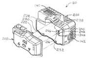
리셋 가능한 파라미터, 데이터 통신, 시스템 모니터링, 알파-뉴메릭 시각 디스플레이 능력 등과 같은 추가의 기능성 및 사용자 인터페이스 능력이, 도20 및 도21에 되고 또한 도2, 도3, 도6 및 도7에 도시된 바와 같이, 확장 모듈(202)을 베이스 모듈(200)에 부착함으로써 제어기(20)에 추가될 수 있다. 도20 및 도21에 도시된 예시적인 확장 모듈(202)은 확장 모듈(202) 자체로부터의 입력 또는 멀리 떨어진 위치로부터 통신 구성요소 또는 이하에 설명된 다른 통신 실시예를 거친 사용자 입력을 처리하는 회로(도20 및 도21에 도시되지 않음)를 포함한다. 확장 모듈은 또한 처리 제어부와 통신하며, 몇몇 실시예에서는 베이스 모듈(200) 내의 온도 상한 제어 회로(296, 298)(도29)와 통신하여, 베이스 모듈(200) 내에 구축된 조정성의 레벨 및 특정 확장 모듈(202) 내에 구축된 능력의 레벨에 따라 베이스 모듈(200)의 일부 또는 모든 기능을 확인, 설정, 리셋 및 모니터링한다. 도20 및 도21에 도시된 바와 같이, 확장 모듈(202)은 하우징(208)의 투명한 전면부(202)를 통해 볼 수 있는 알파-뉴메릭 디스플레이(204), 사용자 입력 버튼(210, 212, 214) 및 상태 LED 디스플레이 너빈(nubbin)(216, 218, 220)을 가지며, 이들은 모두 이하에서 더욱 상세히 설명된다. 확장 모듈(202)은 또한 원격 스테이션 및/또는 데이지 체인 접속된 시스템 내의 다른 제어기(20)와 데이터를 주고받기 위해 데이터 라인 통신 포트(222, 244)를 가질 수 있다. 특정 히터 제어 시스템에 대해 무엇을 원하거나 필요로 하는지에 따라 사용자가 특정한 능력 및 특징의 패키지를 갖는 특정 확장 모듈을 선택 및 설치할 수 있도록 이상의 특징보다 적거나 또는 많은 특징을 갖는 상이한 확장 모듈(200)이 만들어질 수 있다는 것이 주목되어야 한다. 또한, 적외선, RF 또는 다른 무선 통신 실시예와 같은 무선 통신 구성요소 및 그러한 실시예를 위한 구성요소(도시되지 않음)가 원한다면 당업자가 이해하는 바와 같이 확장 모듈 내에 또한 포함될 수 있다. 따라서, 도면에 도시된 통신 포트 및 구성요소는 예시이며, 배타적이거나 또는 실시예를 한정하지 않는다.Additional functionality and user interface capabilities, such as resettable parameters, data communication, system monitoring, alpha-numeric visual display capabilities, etc., are shown in Figures 20 and 21 and also in Figures 2, 3, 6, May be added to thecontroller 20 by attaching theexpansion module 202 to thebase module 200, as shown. Theexemplary expansion module 202 shown in Figures 20 and 21 may be implemented as an input from theexpansion module 202 itself or from a remote location to a communication component or circuitry that handles user input through other communication embodiments described below (Not shown in Figures 20 and 21). The expansion module also communicates with the processing control and in some embodiments communicates with the upper temperaturelimit control circuits 296 and 298 (Figure 29) in thebase module 200 to determine the level of adjustability built into thebase module 200 and the specific Sets, resets, and monitors some or all of the functions of thebase module 200 according to the level of capability built in theexpansion module 202. 20 and 21, theexpansion module 202 includes analphanumeric display 204,user input buttons 210, 212, and 214, which are visible through thetransparent front portion 202 of thehousing 208, 214 and statusLED display nubbins 216, 218, 220, all of which are described in further detail below. Theexpansion module 202 may also have a dataline communication port 222, 244 for exchanging data with anothercontroller 20 in a remote station and / or a daisy-chained system. Adifferent expansion module 200 having fewer or more features than the above features to allow the user to select and install a particular expansion module having a package of specific capabilities and features, depending on what he wants or needs for a particular heater control system, Lt; / RTI > can be made. In addition, wireless communication components such as infrared, RF, or other wireless communication embodiments and components (not shown) for such embodiments may also be included within the expansion module as would be understood by those skilled in the art. Thus, the communication ports and components shown in the figures are illustrative, and are not exclusive or limiting the embodiments.

확장 모듈(202)은 확장 모듈(202)의 후방 패널(256)으로부터 돌출하는 복수의, 예를 들어 3개의 랫치 독(latch dog)(222, 224, 226)을 베이스 모듈(200)의 전방 패널(238) 내의 복수의, 예를 들어 3개의 대응 또는 정합 랫치 구멍(228, 230, 232)과 정렬시키고 제 위치에 스냅 결합시킴으로써, 도21 및 도22에 가장 잘 도시된 바와 같이, 베이스 모듈(200)에 매우 용이하게 부착된다. 확장 모듈(202)은 베이스 모듈(200)로부터 단순히 잡아당겨 분리함으로써 용이하게 제거될 수 있다.Theexpansion module 202 includes a plurality oflatch dogs 222, 224 and 226 protruding from therear panel 256 of theexpansion module 202, for example, 21 and 22, by aligning and snap-engaging a plurality, e.g., three, of matching or matching latch holes 228, 230, 232 in thebase module 238, 200). Theexpansion module 202 can be easily removed by simply pulling and pulling it away from thebase module 200.

베이스 모듈(20) 내의 회로 보드는 예를 들어 접점(236)의 패드 또는 임의의 다른 적절한 플러그 리셉터클과 같은 전기 접점의 세트 및 전방 패널(238)의 개구(246)에 인접한 복수의, 예를 들어 3개의 LED(240, 242, 244)를 갖는다. 대응하게 정렬되고 정합하는 접점 조립체(248) 또는 적절한 플러그가 확장 모듈(202) 내의 회로 보드로부터 후방 패널(256)을 통해 돌출하고, 확장 모듈(202)이 베이스 모듈(200) 상의 제 위치에 스냅 결합될 때 개구(246)를 통해 돌출하여 접점 패드(236) 상의 정합하는 전기 접점과 접촉하거나 또는 베이스 모듈(200) 내의 플러그 리셉터클(도시되지 않음)과 접촉하여, 확장 모듈(202)을 베이스 모듈(200)과 전기적으로 접속시킴으로써 전력을 공급받고 데이터를 통신한다. 또한, 복수의, 예를 들어 3개의 투명 또는 적어도 반투명의 보스 또는 도파관(250, 252, 254)이 확장 모듈(202) 내의 회로 보드에 장착되고, 전방면(206) 상의 디스플레이 너빈(216, 218, 220)과 정렬되고 그것으로부터 연장되어 후방 패널(256)로부터 베이스 모듈(200) 쪽으로 돌출한다. 이들 돌출 보스(250, 252, 254)는 베이스 모듈(200) 내의 LED(240, 242, 244)와 정렬되고, 그리하여 확장 모듈(202)이 베이스 모듈 상의 제 위치에 스냅 결합되면, 보스(250, 252, 254)는 LED(240, 242, 244)로부터 전방면(206) 상의 디스플레이 너빈(216, 218, 220)까지 빛을 전달하도록 LED와 인접하여 위치된다.The circuit board in thebase module 20 may be electrically connected to a plurality of, for example, a plurality of, for example, a plurality of electrical contacts adjacent theopening 246 of thefront panel 238 and a set of electrical contacts such as a pad ofcontacts 236 or any other suitable plug receptacle, And threeLEDs 240, 242, and 244. A correspondingly aligned andmating contact assembly 248 or an appropriate plug protrudes through therear panel 256 from the circuit board in theexpansion module 202 and theexpansion module 202 snaps into place on thebase module 200 When coupled, protrudes throughopening 246 to contact mating electrical contacts oncontact pads 236 or to contact plug receptacles (not shown) inbase module 200 to connectextension module 202 tobase module 200, And is electrically connected to thepower source 200 to receive power and communicate data. Also, a plurality of, e.g., three transparent or at least translucent, bosses orwaveguides 250, 252, 254 may be mounted on the circuit board in theexpansion module 202 and thedisplay nubs 216, 218 And 220 and extends from and protrudes from therear panel 256 toward thebase module 200. These protrudingbosses 250, 252 and 254 are aligned with theLEDs 240, 242 and 244 in thebase module 200 so that when theexpansion module 202 is snapped into place on the base module, 252 and 254 are positioned adjacent to the LEDs to transmit light from theLEDs 240, 242 and 244 to thedisplay nubes 216, 218 and 220 on thefront surface 206.

확장 모듈(202) 없이 베이스 모듈(200)이 단독으로 작동될 때, 먼지와 부스러기가 개구(246)를 통해 베이스 모듈(200) 내로 유입되는 것을 방지하기 위해, 도23에 가장 잘 도시된 바와 같이, 베이스 모듈(202) 상에 확장 모듈(200)을 대신하여 먼지 커버(258)가 제공되어 제 위치로 스냅 결합된다. 먼지 커버는 또한 확장 모듈(202) 상의 랫치 독과 유사한 랫치 독을 가지며, 이것은 베이스 모듈(200) 상의 제 위치에 먼지 커버(258)를 고정하기 위해 랫치 구멍(228, 230, 232)과 정렬되어 그 안으로 스냅 결합된다. 먼지 커버(258)는 LED로부터 상태 디스플레이를 위한 먼지 커버의 전방까지 빛을 전달하도록 먼지 커버(258)의 전방으로부터 LED(240, 242, 244)까지 연장되는, 보스(250, 252, 254)와 유사하지만 그보다 더 짧은 3개의 상태 디스플레이 보스(260, 262, 264)를 갖는다.To prevent dust and debris from entering thebase module 200 through theopening 246 when thebase module 200 is operated alone without theexpansion module 202, , Adust cover 258 is provided on thebase module 202 in place of theexpansion module 200 to snap into place. The dust cover also has a latch dock similar to the latch dock on theexpansion module 202 which aligns with the latch holes 228,230 and 232 to secure thedust cover 258 in place on thebase module 200 It is snapped in. Thedust cover 258 includesbosses 250, 252 and 254 extending from the front of thedust cover 258 to theLEDs 240, 242 and 244 to transmit light from the LEDs to the front of the dust cover for the status display Has three state display bosses 260,262, 264 that are similar but shorter.

물론, 확장 모델 디스플레이 또는 먼지 커버 디스플레이를 위해 더 많거나 더 적은 LED 상태 디스플레이가 제공될 수 있다. 본원에 설명된 예시적인 실시예에 있어서 확장 모듈(202) 상의 3개의 LED 상태 디스플레이 너빈(216, 218, 220) 및 먼지 커버(258) 상의 3개의 LED 상태 디스플레이 보스(260, 262, 264)는 예를 들어 처리 온도 센서(52)로부터의 감지 온도가 너무 높거나 또는 너무 낮은 경우와 같은 주의를 요하는 조건을 제어기(20)가 검출했을 때의 "경보/알람", 히터의 온도가 사전설정된 원하는 작동 범위에 있음을 나타내기 위한 "범위내" 모드, 및 히터로의 제어된 AC 전력이 온 상태로 된 것, 즉 히터에 출력됨을 나타내는 "출력" 모드일 수 있다.Of course, more or fewer LED status displays may be provided for extended model displays or dust cover displays. Three LEDstatus display nubs 216, 218, 220 on theexpansion module 202 and three LEDstatus display bosses 260, 262, 264 on thedust cover 258, in the exemplary embodiment described herein, For example, an "alarm / alarm" when thecontroller 20 detects a condition requiring attention such as a case where the sensed temperature from theprocessing temperature sensor 52 is too high or too low, Quot; in-range "mode to indicate that it is in the desired operating range, and an" output "mode in which the controlled AC power to the heater is turned on, i.e., output to the heater.

상술한 바와 같이, 확장 모듈(202)은 본원에 설명된 기능, 능력 및/또는 특징을 더 많거나 또는 더 적게 제공하도록 설치 또는 프로그래밍될 수 있다. 또한, 몇몇 확장 모듈(202)은 이들 기능, 능력 및/또는 특징을 다른 확장 모듈(202)보다 더 많거나 또는 더 적게 갖도록 만들어질 수 있다. 또한, 확장 모듈(202) 중 하나 는 제1 제어기의 파라미터를 점검 및/또는 리셋하고, 그 후 제2 및/또는 임의의 수의 추가 베이스 모듈(200)의 파라미터를 리셋하기 위해 하나의 베이스 유닛(200)으로부터 다른 베이스 모듈(200)로 이동될 수 있다. 따라서, 원한다면, 단일 확장 모듈(202)이 하나 이상의 베이스 모듈(200)에 사용될 수 있다.As discussed above, theexpansion module 202 may be installed or programmed to provide more or less of the functions, capabilities and / or features described herein. In addition, someexpansion modules 202 may be made to have more or less of these functions, capabilities, and / or features thanother expansion modules 202. In addition, one of theexpansion modules 202 may be used to check and / or reset the parameters of the first controller and then to reset the parameters of the second and / or any number ofadditional base modules 200, (200) to another base module (200). Thus, if desired, asingle expansion module 202 may be used for one ormore base modules 200. [

전자 부품을 손상시킬 수 있는 고온 히터로부터 멀리 제어기(20) 및 관련 배선을 유지하는 것을 돕고 깔끔한 데이지 체인 접속 레이아웃을 유지하는 것을 돕기 위해, 도24 내지 도26에 가장 잘 도시된 바와 같이 제어기(20)에는 편리한 벽 장착 브래킷(270) 및 후방 패널(274)의 정합 잠금 소켓(272)이 제공된다. 브래킷(270)은 복수의 반경방향 연장 이어(ear)(276)를 가지며, 이것은 소켓(272) 내의 인접한 섹터 플레이트(280)들 사이의 정합하는 반경방향 연장 슬롯(278)을 통해 미끄러지도록 크기가 결정된다. 그리하여, 제어기(20)가 회전되면, 이어(276)는 섹터 플레이트 가이드(280) 아래에 붙잡혀서, 브래킷(270)이 소켓(272)으로부터 인출될 수 없도록 한다. 브래킷(270)이 소켓(272) 내로 삽입되면 이어(276) 후방으로 축방향 함몰된 브래킷 상의 몇 개의 백킹 플레이트 가이드(282)가 섹터 플레이트 가이드(280)와 접촉하여, 제어기(20)가 소켓(272)의 축(284)을 중심으로 회전되면, 섹터 플레이트 가이드(280)가 이어(276)와 백킹 플레이트 가이드(282) 사이에 붙잡혀서 브래킷(270)을 견고하게 확실하게 소켓(272) 내에 유지한다.To assist in maintaining thecontroller 20 and associated wiring away from the high temperature heater which can damage the electronic components and to help maintain a neat daisy chain connection layout, the controller 20 A convenientwall mounting bracket 270 and amatching locking socket 272 of therear panel 274 are provided. Thebracket 270 has a plurality of radially extendingears 276 that are sized to slide through matching radially extendingslots 278 betweenadjacent sector plates 280 in thesocket 272 . Thus, when thecontroller 20 is rotated, theear 276 is caught under thesector plate guide 280 such that thebracket 270 can not be withdrawn from thesocket 272. When thebracket 270 is inserted into the socket 272 a number of backing plate guides 282 on the axially recessed bracket backwardly of theear 276 come into contact with thesector plate guide 280 such that thecontroller 20 contacts the socket Thesector plate guide 280 is caught between theear 276 and thebacking plate guide 282 so that thebracket 270 is securely held in thesocket 272 do.

사용시에, 벽 브래킷(270)은 크로스 피스(288)의 구멍(286)을 통과하는 스크류 또는 다른 고정구(도시되지 않음)에 의해 벽 또는 다른 구조체(도시되지 않음)에 체결될 수 있다. 대안적으로, 브래킷(270)은 스트랩, 와이어, 테이프, 또는 크 로스 피스(288) 및 대상물 주위에 감기는 다른 재료(도시되지 않음)에 의해 대상물에, 예를 들어 히터(16)에 체결될 수 있다. 그 후 제어기(20)는 브래킷(270)에 인접하여 위치되고, 축(284) 상의 브래킷(270)과 축방향으로 정렬되며, 브래킷(270)을 향해 축방향으로 가압되어 이어(276)를 지나 슬롯(278)을 통해 소켓(272) 내로 진행한다. 그 후 제어기(20)는 도24에 도시된 바와 같이 브래킷(270) 상의 제 위치에 제어기(20)를 고정하기 위해 축(284)을 중심으로 회전된다. 제어기(20)는 이러한 단계들을 반대로 함으로써 브래킷(270)으로부터 용이하게 제거될 수 있다.In use, thewall bracket 270 may be fastened to a wall or other structure (not shown) by a screw or other fastener (not shown) passing through thehole 286 of thecrosspiece 288. Alternatively, thebracket 270 may be fastened to the object, e.g., to theheater 16, by a strap, wire, tape, or other material (not shown) wrapped around thecrosspiece 288 and the object . Thecontroller 20 is then positioned adjacent thebracket 270 and axially aligned with thebracket 270 on theshaft 284 and axially urged toward thebracket 270 to pass through theear 276 And into thesocket 272 through theslot 278. Thecontroller 20 is then rotated about anaxis 284 to secure thecontroller 20 in position on thebracket 270, as shown in FIG. Thecontroller 20 can be easily removed from thebracket 270 by reversing these steps.

일 실시예에 있어서의 함수 및 제어 로직은 도32의 로직 흐름도과 연계하여 도28 내지 도31의 개략적인 회로도를 주로 참조함으로써 설명될 수 있다. 도28의 개략적인 회로도는 도5 내지 도8에 도시되고 위에서 설명된 바와 같이 단일 포인트 히터 제어 구성(14)에 있어서의 본 발명의 다수 히터 제어 시스템(10)을 도시한다. 요컨대, 마스터 히터(16)는 제어기(20)의 베이스 모듈(200)로의 슬레이브 어댑터 케이블(22)을 거쳐 제어기(20)에 접속된다. 제어기(20)는 제어기(20)에 접속된 T자형 전력 케이블(26)에 의해 예를 들어 AC 전력 공급원과 같은 고전압 전력 소스에 접속된다. 고전압 소스 전력은 T자형 소스 전력 케이블(26) 내의 고전압 와이어(87, 88)에 의해 제어기(20)로 전달되며, 고전압 전도체(290, 292)에 의해 제어기(20)에서 제공된다. 제어기(20)에서, 고전압 소스 전력은 처리 제어 칩(296), 도28 내지 도31에 도시된 실시예의 상한 제어 칩(298), 및 접점 패드(236) 또는 플러그 리셉터클(도시되지 않음)에 저전압 DC 전력을 공급하는 DC 전력 공급원(294)에 의해 탭핑(tapping)되며, 여기에서 확장 모듈(202)이 설치된 경우에 확장 모듈(202)에 사용가능하다. 고전압 제어 전력은 또한 출구 커넥터(142)로 보내지며, 여기에서 슬레이브 어댑터 케이블(22), T자형 슬레이브 제어 전력 케이블(24) 및 슬레이브 단말처리 제어 전력 케이블(184)을 거쳐 히터(16, 16')에 사용가능하다. 마스터 히터(16) 및 슬레이브 히터(16')에서, 제어기 내의 전도체(290, 292)로부터의 고전압 제어 전력은 고전압 와이어(42, 44)에 의해 히터 요소(32)로 전도된다.The function and control logic in one embodiment may be described by referring primarily to the schematic circuit diagrams of Figs. 28-31 in conjunction with the logic flow diagram of Fig. The schematic circuit diagram of Fig. 28 shows the multipleheater control system 10 of the present invention in a single pointheater control configuration 14 as shown in Figs. 5-8 and described above. In short, themaster heater 16 is connected to thecontroller 20 via theslave adapter cable 22 to thebase module 200 of thecontroller 20. Thecontroller 20 is connected to a high voltage power source, such as, for example, an AC power source, by a T-shapedpower cable 26 connected to thecontroller 20. The high voltage source power is delivered to thecontroller 20 by thehigh voltage wires 87,88 in the T-shapedsource power cable 26 and is provided in thecontroller 20 by the high voltage conductors 290,292. In thecontroller 20, the high voltage source power is applied to theprocess control chip 296, the upperlimit control chip 298 of the embodiment shown in Figures 28-31, and thecontact pad 236 or plug receptacle (not shown) Is tapped by aDC power supply 294 supplying DC power to theexpansion module 202 where theexpansion module 202 is installed. The high voltage control power is also sent to theoutlet connector 142 whereheaters 16 and 16 'are connected via aslave adapter cable 22, a T-shaped slavecontrol power cable 24 and a slave terminal processingcontrol power cable 184. [ ). In themaster heater 16 and the slave heater 16 ', the high voltage control power from theconductors 290 and 292 in the controller is conducted to theheater element 32 by thehigh voltage wires 42 and 44.

도28 내지 도31의 개략적인 다이어그램에 도시된 예시적인 제어기(20) 실시예에서, 상한 제어 회로(298)는 상한 차단 기능을 수행하도록 프로그래밍될 수 있는 마이크로프로세서와 같은 디지털 로직 회로를 포함하는 것으로 도시되어 있다. 그러한 디지털 로직 상한 제어 회로에서, 하나의 고전압 전도체(292)는 직접 출구 커넥터(142)로 진행하며, 거기에서부터 각각의 히터(16, 16') 내의 고전압 와이어(44)에 직접 접속된다. 그러나, 다른 고전압 전도체(290)는 2개의 스위치 장치, 예를 들어, 상한 전력 스위치(300) 및 처리 전력 제어 스위치(302)를 통해 진행한다. 제1 스위치 장치, 즉, 상한 전력 스위치(300)는 제2 스위치 장치, 즉, 처리 전력 제어 스위치(302)의 전방에 있으며, 모든 히터(16, 16') 및 제2 스위치 장치(302)를 포함한 제1 스위치 장치(300) 뒤의 모든 것으로의 고전압 전력을 차단 또는 오프시키도록 마이크로프로세서 또는 상한 제어 회로(298) 내의 다른 로직 회로에 의해 제어된다. 따라서, 온도 초과의 발생 등으로 인해 상한 제어기(298)가 제1 스위치 장치(300)를 개방하면, 릴레이 스위치 하류의 어느 것도 제1 스위치 장치(300)가 리셋될 때까지는 작동할 수 없다. 본 설명에서, "상류" 및 "전방"은 예를 들어 AC 전력 소스로부터 전류가 흘러오는 측면, 방향 또는 상대 위치를 지칭한다. 상보적으로, "하류" 또는 "후방" 또는 "뒤"는 예를 들어 전력이 구성요소 등으로부터 멀어지는 방향과 같이 소스로부터 멀어지는 측면, 방향 또는 상대 위치를 지칭한다. 제1 스위치 장치(300), 즉, 상한 전력 스위치는 때때로 본 명세서에서 "상한 스위치", "상한 릴레이 스위치", "상한 전력 릴레이 스위치", "릴레이 전력 스위치", "릴레이 스위치", 또는 여러 예시적인 실시예의 설명에서 유사한 용어로 지칭되지만, 상한 온도 제어에서 히터로 전력을 차단하는 제1 스위치 장치(300)의 주요 기능은 이후 설명된 예시적인 실시예에서 동일하다. 제2 스위치 장치(302), 즉, 처리 전력 제어 스위치는 때때로 본 명세서에서 "처리 전력 스위치", "처리 전력 스위치 조립체", 처리 전력 릴레이 스위치 또는 여러 예시적인 실시예의 설명에서 유사한 용어로 지칭되지만, 처리 온도를 획득하고 유지하기 위해 히터에 전력을 제어하는 제2 스위치 장치(302)의 주요 기능은 이후 설명된 예시적인 실시예에서 동일하다.In theexemplary controller 20 embodiment shown in the schematic diagram of Figures 28-31, the upperlimit control circuit 298 includes a digital logic circuit such as a microprocessor that can be programmed to perform the upper limit cutoff function Respectively. In such a digital logic high limit control circuit, onehigh voltage conductor 292 goes directly to theoutlet connector 142 and is directly connected to thehigh voltage wire 44 in eachheater 16, 16 'from there. However, the otherhigh voltage conductor 290 goes through two switch devices, for example, theupper power switch 300 and the processingpower control switch 302. The first switch device, that is, the upperlimit power switch 300 is located in front of the second switch device, i.e., the processpower control switch 302, and connects all theheaters 16, 16 'and thesecond switch device 302 Controlled by the microprocessor or other logic circuitry within the upperlimit control circuitry 298 to block or turn off the high voltage power to all behind thefirst switching device 300, Thus, when theupper limit controller 298 opens thefirst switch device 300 due to the occurrence of an over-temperature, etc., neither of the relay switches downstream can operate until thefirst switch device 300 is reset. In the present description, "upstream" and "forward" refer to side, direction, or relative positions, for example, where current flows from an AC power source. Complementarily, "downstream" or "rear" or "rear " refers to side, direction, or relative position away from the source, e.g. Thefirst switch device 300, that is, the upper limit power switch is sometimes referred to herein as a "high limit switch", "high limit relay switch", "high limit power relay switch", "relay power switch", "relay switch" The main function of thefirst switching device 300, which is referred to as a similar term in the description of the embodiment, but which blocks power to the heater in the upper temperature control, is the same in the exemplary embodiment described hereinafter. Thesecond switch device 302, i.e., the process power control switch, is sometimes referred to herein as a "process power switch", a "process power switch assembly", a process power relay switch, or similar terms in the description of various exemplary embodiments, The main function of thesecond switching device 302 for controlling power to the heater to obtain and maintain the process temperature is the same in the exemplary embodiment described hereinafter.

제1 고전압, 상한 전력 스위치(300)는 평상시에는 개방되어 있고 따라서 폐쇄하는데 전력이 요구되는 기계식 릴레이인 것이 바람직하지만, 이것이 필수적인 것은 아니다. 또한, 상한 전력 스위치(릴레이)(300)가 일단 개방되면, 상한 전력 스위치(300)는 조작자 또는 사용자의 개입 없이 리셋(폐쇄)될 수 없는 것이 바람직하지만, 이것이 필수적인 것은 아니다. 바꾸어 말하면, 히터에서의 온도가 낮아질 때, 상한 전력 스위치 (릴레이)(300)는 자동으로 리셋 또는 폐쇄되지 않는다. 그 대신, 제어된 전력을 히터에 전달하도록 제어기(20)를 재시동하기 위해서는 상한 전력 스위치 (릴레이)(300)를 리셋(폐쇄)하기 위해 조작자 또는 사용자가 능동적으로 무엇인가를 해야만 한다. 상한 전력 스위치(300)에는 필수적이진 않지만 기계식 릴레이 스위치가 바람직한데, 이는 트라이액과 같은 고체 상태 스위치는 보다 큰 저항을 갖고, 따라서 불필요한 열을 더 많이 발생시키고 불필요한 전력 유출(drain)이 발생하기 때문이다.The first high voltage,high power switch 300 is preferably a mechanical relay that is normally open and therefore requires power to be closed, but this is not necessary. Also, once the upper limit power switch (relay) 300 is open, it is desirable that the upperlimit power switch 300 can not be reset (closed) without the intervention of the operator or the user, but this is not essential. In other words, when the temperature at the heater is lowered, the upper limit power switch (relay) 300 is not automatically reset or closed. Instead, the operator or user must actively do something to reset (close) the upper power switch (relay) 300 to restart thecontroller 20 to deliver the controlled power to the heater. A mechanical relay switch is preferably, but not necessarily, an upperlimit power switch 300 because a solid state switch such as a triac has a greater resistance and therefore generates more unwanted heat and generates unnecessary power drain to be.

통상적인 랫칭 릴레이 장치는 상술한 기능을 수행할 수 있지만, 이러한 종류의 히터 제어 응용예에 사용될 수 있는 통상적인 랫칭 릴레이 장치는 제2 코일 및 상당한 작동 전력을 필요로 하는 크고 거대한 장치이다. 따라서, 본 발명의 일 실시예는 평상시에 개방되어 있는 보통의 기계식 릴레이 스위치를 히터 온도가 온도 상한 아래로 낮아진 후에도 조작자 또는 사용자가 개입할 때까지 개방 상태로 유지시키도록 구성된 상한 제어 회로(298)를 포함한다. 평상시에 개방되어 있는 보통의 기계식 릴레이 스위치가 히터 제어 시스템(10) 내에서 이와 같이 기능할 수 있게 하는 몇 개의 예시적인 상한 제어 회로(298)(하나는 디지털이고 2개는 아날로그 임)가 본 설명에 포함된다.A typical latching relay device can perform the functions described above, but a conventional latching relay device that can be used in this kind of heater control application is a large and massive device that requires a second coil and significant operating power. Thus, one embodiment of the present invention includes an upperlimit control circuit 298 configured to maintain a normally open mechanical relay switch in an open state until an operator or user intervenes even after the heater temperature has dropped below an upper temperature limit, . There are several exemplary upper limit control circuits 298 (one is digital and two are analog) that allow a normal, open mechanical relay switch to function in theheater control system 10 as described herein .

평상시에 개방되어 있는 보통의 기계식 릴레이 스위치는 개방 모드 또는 위치로 스프링 바이어스되는 적어도 한 세트의 전기 접점 및 전력이 공급될 때 스프링 바이어스를 극복하고 접점을 폐쇄하는 자기장 또는 바이어스를 발생시키는 코일을 가진 릴레이 스위치이다. 코일로의 전력이 오프 상태로 되어 전류가 흐르지 않거나 또는 스프링 바이어스를 극복하기에 충분히 강한 전기장을 생성하기에 충분하지 않은 전류가 흐를 때, 스프링 바이어스는 접점을 재개방한다.A normal mechanical relay switch, normally open, has at least one set of electrical contacts that are spring biased to an open mode or position and a relay having a coil that overcomes spring bias and generates a magnetic field or bias that closes the contact Switch. The spring bias reopens the contact when the power to the coil is turned off and no current flows or a current that is insufficient to create an electric field strong enough to overcome the spring bias flows.

상한 전력 (기계식 릴레이) 스위치(300)가 상술한 바와 같이 기능하도록 제어하기 위한 하나의 예시적인 상한 제어 회로(298)는 도28 내지 도31의 제어기(20)의 개략적인 회로도에 도식적으로 표시된 바와 같이 디지털 로직 마이크로프로세서 또는 다른 로직 회로를 포함한다. 이 예에서, 상한 회로(298)의 마이크로프로세서 또는 다른 디지털 로직 회로는 시동되었을 때 (i) 제1 (상한) 온도 센서(50)에 의해 감지된 온도를 사전설정된 온도 상한과 비교하고, (ii) 감지된 온도가 사전설정된 온도 상한과 동일하지 않거나 그것을 초과하지 않은 경우에 평상시에 개방되어 있는 상한 전력 릴레이 스위치(300)를 폐쇄하는 신호를 발생시키는 것을 포함하는 일련의 시동 로직 단계(시동 로직)를 통해 진행하도록 프로그래밍된다. 예를 들어, 그러나 제한을 목적으로 하지 않고, 기계식 상한 전력 릴레이 스위치(300)의 코일을 통한 저전압 DC 전류의 흐름을 온 상태로 하여 스위치를 폐쇄하기 위해 예를 들어 트랜지스터(도시되지 않음)와 같은 저전압 고체 상태 스위치의 게이트에 신호가 인가될 수 있다. 감지된 온도가 온도 상한과 동일하지 않거나 또는 초과하지 않는 경우에, 시동 로직은 상한 전력 릴레이 스위치(300)를 폐쇄시키는 신호를 발생시키지 않는다. 따라서, 하나의 예시적인 실시예에서, 상한 전력 릴레이 스위치(300)가 폐쇄되지 않은 경우에, 상한 제어 회로에 전력을 공급하는 DC 전력이 오프 상태로 되어야 하며, 그 후 상한 전력 릴레이 스위치(300)가 개방된 후에 그것을 폐쇄하기 위해 감지된 온도가 사전설정된 온도 상한을 초과하지 않을 때 리부팅 또는 재시동 로직를 거치도록 다시 온 상태로 된다. 상한 제어 회로(298)로의 DC 전력을 그와 같이 오프시키거나 제거하는 것은 다양한 방법으로 달성될 수 있다. 예를 들어, 그러나 제한을 목적으로 하지 않고, 도28의 예시적인 실시예에서 상한 제어 회로(298)를 작동시키기 위해 DC 전력을 제공하는 DC 전력 공급원(294)은 AC 전력 리드(290, 292) 내의 AC 전력으로 탭핑되기 때문에, 상한 제어 회로(298)로부터의 DC 전력의 제거는 AC 소스 전력으로부터 제어기(20)를 언플러그 또는 단절시킴으로써 간단히 달성될 수 있고, 이는 또한 DC 전력 공급원(294)으로의 전력을 차단시켜 상한 제어 회로(298)로부터 전력을 제거한다. 그 후, 제어기(20)를 AC 소스 전력에 재접속하여 상한 제어 회로(298)에 다시 전력을 공급함으로써 재부팅되어 다시 시동 로직을 거치도록 하며, 상술한 바와 같이 감지된 온도가 사전설정된 온도 상한과 동일하지 않거나 그것을 초과하지 않는다고 시동 로직이 판단한 경우에 상한 전력 릴레이 스위치(300)를 폐쇄할 것이다. 물론, 상한 회로(298)로의 DC 전력을 온/오프시키는 다른 방법이 또한 제공될 수 있으며, 예를 들어 AC 전력을 DC 전력 공급원(294)으로 오프 및 온 변환시키도록 DC 전력 공급원(294)의 전방에 또는 DC 전력 공급원(294)과 상한 회로(298) 사이에 수동 조작 스위치(도시되지 않음)가 또한 제공될 수 있다. 상한 제어 회로(298)를 위한 적절한 로직 회로는 예를 들어 미국 캘리포니아주 산 호세의 암텔 코포레이션(Amtel Corporation)에 의해 제조되는 ATmega168 마이크로프로세서를 포함하지만, 설명된 기능을 수행하도록 프로그래밍될 수 있는 다른 집적 회로 칩이 상업적으로 용이하게 구입가능하고, 당업자에게 잘 알려져 있다.One exemplary upperlimit control circuit 298 for controlling the high power (mechanical relay)switch 300 to function as described above is shown schematically in the schematic circuit diagram of thecontroller 20 of Figures 28 - As well as digital logic microprocessors or other logic circuits. In this example, the microprocessor or other digital logic circuit of theupper limit circuit 298 is configured to (i) compare the temperature sensed by the first (upper)temperature sensor 50 with a predetermined upper temperature limit, and Generating a signal to close the normally open upper limitpower relay switch 300 when the sensed temperature is not equal to or greater than a predetermined temperature upper limit (start-up logic) Lt; / RTI > For example, but not for the purpose of limitation, it is also possible, for example, to switch the flow of low-voltage DC current through the coil of the mechanical upper limitpower relay switch 300 to the ON state, A signal may be applied to the gate of the low voltage solid state switch. If the sensed temperature is not equal to or exceeds the upper temperature limit, the startup logic does not generate a signal to close the upperpower relay switch 300. Thus, in one exemplary embodiment, when the upperpower relay switch 300 is not closed, the DC power that powers the upper limit control circuit must be turned off, then the upperpower relay switch 300, When the sensed temperature does not exceed the predetermined temperature upper limit to shut it down after it is opened, it is turned on again to undergo the rebooting or rebooting logic. Turning off or removing DC power to the upperlimit control circuit 298 as such can be accomplished in a variety of ways. For example, but not for the purpose of limitation, aDC power supply 294 providing DC power for operating the upperlimit control circuit 298 in the exemplary embodiment of FIG. 28 includes anAC power lead 290, 292, The removal of the DC power from the upperlimit control circuit 298 may be accomplished simply by unplugging or disconnecting thecontroller 20 from the AC source power and this may also be accomplished by theDC power supply 294 Lt; RTI ID = 0.0 > 298 < / RTI > Thereafter, thecontroller 20 is reconnected to the AC source power to supply power to the upperlimit control circuit 298 again to cause it to go through the startup logic again, and the sensed temperature is equal to the preset upper temperature limit The upperpower relay switch 300 will be closed if the startup logic determines that it does not or does not exceed it. Of course, other methods of turning on / off DC power to theupper limit circuit 298 may also be provided and may be provided to theDC power supply 294 to turn off and on the AC power to theDC power supply 294, for example. A manual operation switch (not shown) may also be provided in front of or between theDC power supply 294 and theupper limit circuit 298. Suitable logic circuits for the upperlimit control circuitry 298 include, for example, the ATmega168 microprocessor manufactured by Amtel Corporation of San Jose, CA, but other integrated circuits that can be programmed to perform the described functions Circuit chips are commercially available commercially and are well known to those skilled in the art.

다시, 본 예시적인 디지털 실시예의 목적은 상한 제어 회로(298)에 의해 오프 상태로 된 히터를 재시동하기 위해 조작자 또는 사용자가 능동적으로 개입할 것을 요구하고, 그에 따라 조작자 또는 사용자가 히터를 다시 온 상태로 하여 내버려두기 전에 히터의 상한 차단의 원인을 점검할 가능성을 증가시키는 것이다. 동시에, 상술한 방식으로, 즉 사전설정된 온도 상한에서 또는 그 근처에서 신뢰성있는 방식으로 히터로의 AC 전력을 개방 및 차단하고, 그 후 간단한 조작자 개입에 의해 다시 폐쇄 가능한 방식으로 제어되는 기계식 릴레이 스위치(300)의 사용은 교체되어야 하거나 히터를 쓸모없게 만드는 히터의 열 융합의 단점을 회피한다. 또한, 예를 들어 크고 거대하며 전력 유출되는 것과 같은 통상적인 랫칭 릴레이의 단점을 회피하고, 예를 들어 저항, 발열 및 전력 유출과 같은 고체 상태 스위치의 단점을 회피한다. 또한, 상술한 디지털 실시예에서, 온도 상한 또는 파라미터는 조정가능하며, 이는 사용자에게 추가적인 옵션 또는 융통성을 제공한다.Again, the purpose of this exemplary digital embodiment is to require the operator or user to actively intervene to restart the heater turned off by the upperlimit control circuitry 298, thereby causing the operator or user to turn the heater back on The possibility of checking the cause of the upper limit cutoff of the heater is increased. At the same time, a mechanical relay switch (not shown) which opens and closes the AC power to the heater in a manner described above, i.e. in a reliable manner at or near a predetermined temperature upper limit, and which is then controlled in a closedable manner bysimple operator intervention 300 avoids the disadvantages of thermal fusion of the heater which must be replaced or render the heater useless. It also avoids the disadvantages of conventional latching relays, such as large and large, power outflows, and avoids the disadvantages of solid state switches such as, for example, resistance, heat generation and power drain. Further, in the above-described digital embodiment, the upper temperature limit or parameter is adjustable, which provides the user with additional options or flexibility.

당업자가 아는 바와 같이, 프로그래머가 사용을 위해 선택한 특정 로직 명령문이 아닌 값과 파라미터가 "동일하거나 또는 더 크거나" 또는 단순히 그 값보다 "더 큰" 경우에, 동작을 발생시키는 로직 단계 사이에는, 실질적인 차이가 만약 있다 하더라도 적다. 마찬가지로, 파라미터가 그 값과 "동일하거나 또는 더 작거나" 또는 단순히 그 값보다 "더 작은" 경우에 동작을 발생시키는 로직 단계 사이에는, 실질적인 차이가 만약 있다 하더라도 적다. 다시 말해, 예를 들어, 감지된 온도가 사전설정된 온도 상한 파라미터와 같거나 그보다 클 때 상한 회로의 로직 단계가 릴레이(300)를 개방하도록 신호를 발생시키는 것으로 설명 또는 주장된다면, 이는 감지된 온도가 온도 상한 파라미터를 초과할 때, 즉 더 클 때, 릴레이(300)를 개방하도록 신호를 발생시키는 것과 동일한 것으로 간주된다. 따라서, 달리 특정되지 않는다면, ">="는 ">"과 동일하다고 간주되며, "<="는 "<"과 동일하다고 간주된다.As will be appreciated by those skilled in the art, between logic steps that generate an operation when the value and parameter are not " the same or greater "or simply" larger "than the particular logic statement selected for use by the programmer, There are substantial differences if any. Likewise, even if there is a substantial difference between the logic steps that cause the operation to occur when the parameter is "equal to or less" or simply "smaller" than its value. In other words, if the logic step of the upper limit circuit is described or claimed to generate a signal to open therelay 300, for example, when the sensed temperature is equal to or greater than the predetermined temperature upper limit parameter, Is considered equal to generating a signal to open therelay 300 when the temperature upper limit parameter is exceeded, i.e., when it is greater. Therefore, unless otherwise specified, "> =" is considered equal to ">" and "<=" is considered equal to "<".

마스터 히터(16)의 온도가 상한 제어부(298)에서 설정된 온도 상한 아래에 유지되는 한, 제1 스위치는 폐쇄 상태로 유지되고, 히터(16, 16')는, 예를 들어 서모커플 또는 서미스터일 수 있는 마스터 히터(16) 내의 제2 온도 센서(52)로부터의 온도 신호에 기초하여 제어기(20) 내의 처리 제어부(296)에 의해 제어된다. 도28에 도시된 바와 같이, 제2 온도 센서(52)로부터의 신호는 히터(16) 내의 저전압 와이어(58, 60)에 의해, 그리고 슬레이브 어댑터 케이블(22)(도15)을 통과하는 저전압 와이어 쌍에 의해 제어기(20) 내의 증폭기(306)에 공급되며, 여기에서 처리 제어부(296)에 의한 사용을 위해 조절 및 증폭된다.As long as the temperature of themaster heater 16 is maintained below the set upper temperature limit in theupper limit controller 298, the first switch is kept in the closed state and theheaters 16 and 16 ' And is controlled by theprocessing control unit 296 in thecontroller 20 based on the temperature signal from thesecond temperature sensor 52 in themaster heater 16. [ 28, the signal from thesecond temperature sensor 52 is applied by thelow voltage wires 58, 60 in theheater 16 and by thelow voltage wires 58, 60 passing through theslave adapter cable 22 Is supplied to theamplifier 306 in thecontroller 20 by a pair, where it is conditioned and amplified for use by theprocessing control 296.

도32에 더욱 상세히 도시된 바와 같이, 기본적으로, 처리 제어부(296)는 제2 온도 센서(52)에 의해 감지된 온도를 처리 제어부(296)에서 설정된 소정 범위 내에 유지하기 위해, 히터(16, 16')로의 고전압 AC 전력을 온/오프시키도록 제2 (처리 전력) 스위치(302)를 작동시킨다. 도28에 도시된 예시적인 실시예의 처리 전력 스위치(302)는 아크 및 열을 최소화하기 위해 병렬 관계인 2개의 스위치, 즉 기계식 릴레이 스위치(303) 및 고체 상태 트라이액 스위치(305)를 포함하는 조립체이며, 이에 따라 때때로 본 명세서에서 처리 전력 스위치 조립체(302)로도 지칭된다. 고체 상태 트라이액 스위치(305)는 기계식 릴레이 스위치(303) 내의 접점들의 초기 폐쇄 동안 기계식 릴레이 스위치(303) 내의 아크를 최소화하기 위해 기계식 릴레이 스위치(303)가 폐쇄되기 직전, 예를 들어 약 20 밀리세컨드 전에 온 상태로 된다. 그 후 고체 상태 트라이액 스위치(305)는 기계식 릴레이 스위치(303)가 폐쇄되어 히터(16, 16')에 제어된 AC 전력을 전도하는 동안 고체 상태 트라이액 스위치 (305) 내에서의 발열을 방지하기 위해 기계식 릴레이 스위치(303)가 폐쇄되고 나서 약 20 밀리세컨드 후에 오프 상태로 된다. 그 후, 고체 상태 트라이액 스위치(305)는 기계식 릴레이 스위치(303)가 개방될 때의 아크를 최소화하기 위해 기계식 릴레이 스위치(303)가 개방되기 직전에 온 상태로 된다. 이 기능들은 당업자가 이해하는 바와 같이 처리 제어 회로(296)에 의해 제어된다. 기계식 릴레이 스위치 및 고체 상태 트라이액 전력 스위치는 당업자에게 잘 알려진 바와 같이 많은 제조자들로부터 다양한 크기 및 구성의 것을 상업적으로 용이하게 구입가능하다.32, theprocess control unit 296 controls the heater 16 (see FIG. 32) to maintain the temperature sensed by thesecond temperature sensor 52 within a predetermined range set by theprocess control unit 296. [ (Processing power)switch 302 to turn on / off the high voltage AC power to the first (processing power) 16 '. Theprocessing power switch 302 of the exemplary embodiment shown in FIG. 28 is an assembly that includes two switches in parallel relationship to minimize arc and heat, namely, amechanical relay switch 303 and a solidstate triac switch 305 , And thus is sometimes also referred to herein as the processpower switch assembly 302. The solidstate triac switch 305 may be activated prior to themechanical relay switch 303 being closed to minimize the arc in themechanical relay switch 303 during the initial closing of the contacts in themechanical relay switch 303, It is turned on before the second. The solidstate triac switch 305 then prevents heat generation in the solidstate triac switch 305 while themechanical relay switch 303 is closed to conduct the controlled AC power to theheaters 16 and 16 ' Themechanical relay switch 303 is turned off to be turned off after about 20 milliseconds. Thereafter, the solidstate triac switch 305 is turned on just before themechanical relay switch 303 is opened to minimize the arc when themechanical relay switch 303 is opened. These functions are controlled by theprocess control circuitry 296 as will be appreciated by those skilled in the art. Mechanical relay switches and solid state triac power switches are commercially available in a variety of sizes and configurations from many manufacturers, as is well known to those skilled in the art.

처리 제어 회로(296)는 또한 도32에 더 상세히 도시된 다수의 다른 기능을 제공하며, 이 기능은 예를 들어 녹색, 호박색 및 적색 LED 광 디스플레이(240, 242, 244)의 디스플레이를 작동시키기 위한 정보를 처리하고, 확장 모듈(202)과 베이스 모듈(200) 사이에서 정보를 교환하고, 디스플레이 및 상한 전력 스위치(300)의 상태에 관련된 출력을 처리하기 위한 상한 제어부로부터의 신호를 수신하는 것을 포함하지만, 이들에 한정되는 것은 아니다. 처리 제어 회로(296)는 또한 암텔 코포레이션에 의해 제조되는 ATmega168을 포함할 수 있지만, 이러한 기능 및 다른 기능을 담당할 수 있는 수많은 다른 마이크로프로세서가 당업자에게 알려져 있고 용이하게 구입가능하다.Theprocessing control circuit 296 also provides a number of other functions, which are shown in more detail in Fig. 32, for example, for activating the display of green, amber and red LEDoptical displays 240, 242, 244 Includes processing information, exchanging information between theexpansion module 202 and thebase module 200, and receiving signals from the upper limit control for processing outputs related to the status of the display and theupper power switch 300 However, the present invention is not limited thereto. Theprocessing control circuitry 296 may also include ATmega 168, which is manufactured by Microtel Corporation, but numerous other microprocessors capable of performing these and other functions are known to those skilled in the art and are readily available for purchase.

처리 제어부(296)에 의해 제공되는 기능들 중 하나는 하나 또는 복수의 히터(16)가 원하는 온도 범위 내에서 작동하고 있는지를 확인하기 위해 원격 모니터링 위치에 전달되어야 할 온도 범위 신호("경보/알람 신호"로 지칭되기도 함)를 발생시키기 위해 온도 입력 정보를 처리하는 것이다. 이 기능은 다수의 용도를 담당할 수 있다. 예를 들어, 히터 온도가 상술한 온도 상한에 관련되어 있거나 또는 관련되어 있지 않을 수 있는 특정한 원하는 작동 범위 밖에 있는 경우에, 이 전자적 온도 범위 신호는 장비 인터록, 즉 특정 온도 범위 내에 열을 유지하기 위해 적절히 작동하는 히터(16)에 의존하는 공업적 처리를 방지 또는 저지하기 위한 기구(도27)의 트리거링에 사용될 수 있다. 그러한 전자적 온도 범위 신호의 다른 용도는 멀리 떨어진 위치의 조작자를 위해 통지 또는 알람 기능을 발생시켜 조작자에게 히터 또는 히터의 그룹이 원하는 작동 범위 밖에 있음을, 즉 너무 차거나 또는 너무 뜨거움을 알려주는 것일 수 있다. 물론, 그러한 전자적 온도 범위 또는 "범위외" 신호의 용도는 이러한 예들에 한정되지 않는다.One of the functions provided by theprocess control unit 296 is a temperature range signal ("alarm / alarm ") to be communicated to the remote monitoring position to verify that one ormore heaters 16 are operating within a desired temperature range Quot; signal "). &Lt; / RTI &gt; This function can serve many purposes. For example, if the heater temperature is outside of a particular desired operating range that may or may not be related to the above-described temperature upper limit, the electronic temperature range signal may be a device interlock, i.e., to maintain heat within a certain temperature range May be used for triggering a mechanism (Fig. 27) for preventing or inhibiting industrial processes that rely on properly operatingheater 16. Another use for such an electronic temperature range signal is to generate a notification or alarm function for an operator at a remote location so that the operator is informed that the group of heaters or heaters is outside the desired operating range, i.e., too hot or too hot . Of course, the use of such electronic temperature ranges or "out of range" signals is not limited to these examples.

본 발명의 전자적 온도 범위 신호("경보/알람 신호"로도 지칭됨)를 실시하기 위해, 처리 제어부(296)에 의해 작동될 수 있는 전자 릴레이 장치(310)가 제어기(20)에 제공된다. 공장-사전설정된 또는 사용자가 정한 히터(16)의 원하는 온도 범위가 처리 제어부(296) 내에 프로그래밍된다. 이 범위는 절대값으로 또는 상하한으로 설정될 수 있으며, 조작자의 요구에 따라 고정되거나 또는 변동될 수 있는 몇몇 작동 온도 설정값 부근의 증분 값일 수 있다.To implement the electronic temperature range signal of the present invention (also referred to as an "alarm / alarm signal"), anelectronic relay device 310, which can be actuated by theprocess control 296, The desired temperature range of the factory-preset or user-definedheater 16 is programmed into theprocessing control 296. This range may be set to an absolute value or an upper and lower limit, and may be an increment value near some operating temperature set point which may be fixed or varied according to the operator &apos; s request.

제어기(20)가 제어기(20)의 데이지 체인 시리즈 내의 마지막 제어기(20)이거 나 또는 시스템 내의 유일한 제어기(20)인지에 따라, 위에서 설명되고 도10 내지 도30에 도시된 바와 같이, 원격 모니터링 장치(15)(도27)에 의해 공급되는 30볼트 이하의 저전압이 T자형 소스 전력 케이블 섹션(26)에 제공된 저전압 와이어(98, 100 및/또는 102, 104)를 거쳐 그리고/또는 단말처리된 소스 전력 케이블 섹션(106)의 저전압 와이어(118, 120)를 거쳐 제어기(20)에 전달된다.10 to 30 as described above, depending on whether thecontroller 20 is thelast controller 20 in the daisy chain series of thecontroller 20 or theonly controller 20 in the system, A low voltage of 30 volts or less supplied by the power source 15 (Figure 27) is applied to the T-shaped sourcepower cable section 26 via thelow voltage wires 98, 100 and / or 102, 104 and /Voltage wires 118 and 120 of thepower cable section 106 to thecontroller 20.

제어기(20)에서, 저전압 신호 전도체들 중 하나는 T자형 소스 전력 케이블(26) 또는 단말처리된 소스 전력 케이블(106)(도28에 도시되지 않음, 도12 및 도13 참조)로 되돌아 가기 전에, 도28의 트레이스(312, 314)에 의해 도시된 바와 같이, 릴레이 장치(310)를 통과한다. 원격 위치(15)의 원격 모니터 장치(도27)가 단말처리된 소스 전력 케이블(106) 내의 T자형 소스 전력 케이블(26 및/또는 118, 120) 내의 저전압 와이어(98, 100 및/또는 102, 104)에 접속되어, 이들 저전압 와이어 상의 전압 및/또는 전류를 모니터링한다. 예를 들어, 하나 이상의 T자형 소스 전력 케이블(26, 106) 중 하나 이상 또는 단말처리 소스 전력 케이블(106)을 거쳐 "15"의 위치에 있는 원격 모니터링 장치에 접속된 모든 제어기(20) 내의 모든 릴레이 장치(310)가 폐쇄된 경우, 전류가 흐르고 그리고/또는 전압이 떨어질 것이다. 다른 한편으로는, 임의의 제어기(20) 내의 임의의 릴레이 장치(310)가 개방되면, 어떠한 소스 전력 케이블(26) 내의 저전압 라인을 통해서도 전류가 흐르지 않을 것이고, 그리고/또는 전압은 최고 전압, 즉 원격 모니터링 장치(15)에 의해 저전압 와이어에 인가된 개방 회로 전압이 될 것이다. 그러한 전압 및/또는 전류 상태는 원격 모니터링 스테이션(15) 내의 연속성 검출기(31)에 의해 모니터링되며, 따라서 모든 제어기의 모든 릴레이 장치(310)가 폐쇄되었는지를 검출할 수 있고, 따라서 모든 히터(16)가 원하는 온도 범위 내에서 작동하고 있음을 나타내거나(폐쇄된 신호 회로 상태), 또는 히터(16)들 중 적어도 하나가 원하는 온도 범위 내에서 작동하지 않음을 나타낼 수 있다(개방 신호 회로 상태). 따라서, 데이지 체인 접속 시리즈 내의 마지막 또는 유일한 제어기(20)가 도10 내지 도11 및 도28에 도시된 T자형 소스 전력 케이블(26)이 아닌 도12 내지 도13에 도시된 단말처리된 제어 전력 케이블(106)을 거쳐 원격 모니터링 장치에 접속되어야 하는 이유가 명확해진다. 구체적으로, 마지막 T자형 소스 전력 케이블(26)에 접속된 제어기(20)가 없다면, 저전압 신호 회로는 예를 들어 도28의 비접속 와이어(102, 104)와 같은 비접속 커넥터(112)에서 항상 개방되어 있을 것이고, 따라서 히터(16)가 원하는 범위 밖에서 작동하는 것으로 거짓 표시할 것이다. 직선형 단말처리 소스 전력 케이블(106)은 도29에 도시된 바와 같이 그러한 문제들을 방지한다.In thecontroller 20, one of the low-voltage signal conductors is connected to a T-shapedsource power cable 26 or a terminal-treated source power cable 106 (not shown in FIG. 28, see FIGS. 12 and 13) And passes throughrelay device 310, as shown bytraces 312 and 314 in FIG. The remote monitoring device (Figure 27) of theremote location 15 is connected to thelow voltage wires 98, 100 and / or 102 in the T-shapedsource power cable 26 and / or 118, 120 within the terminal- 104 to monitor the voltage and / or current on these low voltage wires. For example, all of all of thecontrollers 20 connected to the remote monitoring device at "15 " position via one or more of the one or more T-shapedsource power cables 26, Whenrelay device 310 is closed, current will flow and / or voltage will drop. On the other hand, if anyrelay device 310 in anycontroller 20 is open, no current will flow through the low voltage line in anysource power cable 26 and / or the voltage is at the highest voltage, i. E. It will be the open circuit voltage applied to the low voltage wire by theremote monitoring device 15. Such a voltage and / or current state is monitored by thecontinuity detector 31 in theremote monitoring station 15 and thus can detect if all therelay devices 310 of all the controllers are closed, (Closed signal circuit state), or at least one of theheaters 16 is not operating within the desired temperature range (open signal circuit state). Thus, if the last or onlycontroller 20 in the daisy chain connection series is not the T-shapedsource power cable 26 shown in Figs. 10-11 and 28, but the terminally processed control power cable It is clear that the reason why it should be connected to the remote monitoring apparatus via thenetwork 106 is discussed. Specifically, if there is nocontroller 20 connected to the last T-shapedsource power cable 26, then the low voltage signal circuit is always present in thenon-connecting connector 112, such as thenon-connecting wires 102, It will be open and thus theheater 16 will falsely indicate operating outside the desired range. The straight terminal processingsource power cable 106 prevents such problems as shown in Fig.

요컨대, T자형 소스 전력 케이블(26)과 데이지 체인 접속된 시리즈 내의 각 제어기(20) 및 단말처리된 소스 전력 케이블(106)과 접속된 시리즈 내의 마지막 제어기(20)는 원하는 온도 작동 범위로 프로그래밍되었다. 온도 센서(52) 또는 2개의 온도 센서(50, 52)가 원하는 온도 범위 밖의 온도를 표시하지 않는 것으로 제어기(20)의 제어 처리부(296)가 판단하는 한, 제어 처리 회로(296)는 릴레이 장치(310)를 폐쇄 상태로 유지시킨다. 그러나, 제어기(20)가 감지된 온도 정보로부터, 히터(16)가 원하는 온도 범위 내에서 작동하지 않는다고 판단하면, 제어기는 릴레이 장치(310)를 개방할 것이고, 따라서 저전압 신호 회로를 개방할 것이며, 이는 원격 모니터링 위치(15)(도27)의 연속성 검출기(31)에 의해 검출 가능하다. 그 결과, 연속성 검출기(31)로부터의 신호는 상술한 바와 같이 어떠한 목적에서든 알람, 통지 및/또는 제어 또는 인터록 신호를 발생시킬 수 있다.In short, thelast controller 20 in the series connected with eachcontroller 20 and the terminal-processedsource power cable 106 in the series daisy-chained with the T-shapedsource power cable 26 was programmed to the desired temperature operating range . Thecontrol processing circuit 296 determines that the temperature of thetemperature sensor 52 or the temperature of the twotemperature sensors 50 and 52 does not indicate a temperature outside the desired temperature range, as long as thecontrol processing unit 296 of thecontroller 20 determines that, (310) in the closed state. However, if thecontroller 20 determines from the sensed temperature information that theheater 16 is not operating within the desired temperature range, the controller will open therelay device 310 and thus open the low voltage signal circuit, This is detectable by thecontinuity detector 31 of the remote monitoring position 15 (Fig. 27). As a result, the signal from thecontinuity detector 31 can generate an alarm, notification and / or control or interlock signal for any purpose, as described above.

상술한 바와 같이, 그리고 도28에 도시된 바와 같이, 마스터 히터(16) 내의 온도 센서(50, 52)는 슬레이브 어댑터 케이블(22)에 의해 제어기(20)에 접속되고, 제어기(20)는 상술한 처리에서 마스터 히터(16) 내의 이들 온도 센서(50, 52)로부터의 신호를 사용한다. 그러나, 슬레이브 히터(16')가 동일한 온도 센서(50, 52)를 갖는 것을 포함하여 몇몇 실시예의 마스터 히터(16)와 동일한 구조이더라도, 슬레이브 히터(16')의 이들 온도 센서(50, 52)는 제어기(20)에 접속되지 않는다. 슬레이브 어댑터 케이블(22)의 슬레이브 케이블 세그먼트(128)에 저전압 와이어가 없고 T자형 슬레이브 히터 케이블(24) 또는 단말처리된 제어 전력 슬레이브 케이블(184) 내에 저전압 전도체가 없는 상태에서, 제어기(20)는 슬레이브 히터(16') 내의 센서(50, 52)로부터 어떠한 온도 신호도 수신하지 않으며, 이것이 그들을 슬레이브 히터(16')로서 기능하게 하는 이유이다. 제어기(20)가 고전압 전력을 온/오프시키는 것, 온도 범위 릴레이(310)를 작동시키는 것 또는 히터 온도에 기초한 다른 기능 중 무엇을 하기로 결정하였든지 간에, 그것은 마스터 히터(16) 내의 온도 센서(50, 52)에 의해 감지된 온도에 기초한다.28, thetemperature sensors 50, 52 in themaster heater 16 are connected to thecontroller 20 by aslave adapter cable 22, In one process, signals from thesetemperature sensors 50, 52 in themaster heater 16 are used. However, even though the slave heater 16 'has the same structure as themaster heater 16 of some embodiments, including thesame temperature sensors 50 and 52, thesetemperature sensors 50 and 52 of the slave heater 16' Is not connected to the controller (20). With no low voltage wire in theslave cable segment 128 of theslave adapter cable 22 and no low voltage conductor in the T-shapedslave heater cable 24 or the terminated controlpower slave cable 184, thecontroller 20 Does not receive any temperature signal from thesensors 50, 52 in the slave heater 16 ', which is why they make them function as the slave heater 16'. Whethercontroller 20 turns on / off high voltage power, activatestemperature range relay 310, or any of the other functions based on heater temperature, (50, 52).

상술한 바와 같이, 상술한 바와 같이 작동하기 위해 상한 제어부(298) 및 처리 제어부(296)에 의해 요구되는 모든 파라미터는 제어기(20)의 베이스 모듈(200)에 구축된 처리 제어부(296) 및 상한 제어부(298) 내에 프래그래밍 또는 사전설정될 수 있다. 그러나, 더 많은 제어, 기능성, 모니터링 또는 다른 능력이 요구된다면, 그러한 추가의 제어, 기능성, 모니터링 또는 다른 능력이 상술한 바와 같이 베이스 모듈(200)(도20 내지 도22)에 부착되는 확장 모듈(202)에 제공될 수 있다. 도28에 도시된 예시적인 확장 모듈(202)은 디스플레이/조정 마이크로프로세서(316), 알파-뉴메릭 디스플레이(204), 사용자 인터페이스 버튼(210, 212, 214), 디지털 통신 입력/출력 포털(222, 224) 및 통신 마이크로프로세서(318)를 포함한다. 디스플레이/조정 마이크로프로세서(316)가 또한 암텔 코포레이션에 의해 제조되는 ATmega168일 수 있지만, 수많은 다른 마이크로프로세서가 또한 사용될 수 있다.All of the parameters required by theupper limit controller 298 and theprocess controller 296 to operate as described above are stored in theprocessing controller 296 and upper limit set in thebase module 200 of thecontroller 20, May be flagged or preset in thecontrol unit 298. However, if additional control, functionality, monitoring, or other capabilities are required, such additional control, functionality, monitoring, or other capability may be provided to the base module 200 (Figs. 20-22) 202). Theexemplary expansion module 202 shown in Figure 28 includes a display /tuning microprocessor 316, analphanumeric display 204,user interface buttons 210, 212 and 214, a digital communication input /output portal 222 , 224, and acommunication microprocessor 318. The display /tuning microprocessor 316 may also be ATmega 168, which is also manufactured by the Amtell Corporation, but a number of other microprocessors may also be used.

디스플레이/조정 마이크로프로세서(316)는 사용자 인터페이스 버튼(210, 212, 214)에 접속되고, 이 버튼들은 디스플레이/조정 마이크로프로세서(316)가 처리 제어부(296) 및/또는 상한 제어부(298)와 주고 받으며 또한 디스플레이(204)로 보내는 다양한 파라미터 및 정보를 검색 및 리셋하는데 사용될 수 있다. 마이크로프로세서(316)를 이용하여 검색, 디스플레이 및 리셋될 수 있는 그러한 정보는 원하는 작동 온도 설정 포인트, 안전 온도 상한, 고온 경보 설정 포인트, 저온 경보 설정 포인트, 히스테리시스, 출력 PID(proportional band, integral, deviation), 사이클 시간, 주변 온도(판독만), 모드버스(modbus) 장치 어드레스, 모드버스 밴드율, 온도 단위(섭씨 또는 화씨)를 포함할 수 있지만, 이들에 한정되는 것은 아니다.The display /tune microprocessor 316 is connected to user interface buttons 210,212 and 214 which allow the display /tune microprocessor 316 to communicate with theprocess control 296 and / or thehigh limit control 298 And may also be used to retrieve and reset various parameters and information that are sent to thedisplay 204. Such information that can be retrieved, displayed, and reset using themicroprocessor 316 includes a desired operating temperature set point, a safety temperature upper limit, a high temperature alarm set point, a low temperature alarm setpoint, hysteresis, proportional band, integral, deviation ), Cycle time, ambient temperature (read only), modbus device address, modbus band rate, temperature unit (Celsius or Fahrenheit).

통신 마이크로프로세서(318)는 입력/출력 포트(222, 224)를 거쳐 정보를 입출력하고, 조정을 행하고, 프로그래밍을 수정하기 위해 원격 모니터링 또는 제어 스테이션, 서비스 컴퓨터 등과의 외부 데이터 통신을 가능하게 한다. 통신 마이크로프로세서(318)는 송신기 및 수신기를 가진, 예를 들어 미국 캘리포니아주 서니베일(Sunnyvale)의 맥심 인테그레이티드 프로덕트(Maxim Integrated Products)에 의해 제조되는 MAX3157일 수 있지만, 당업자에게 알려진 바와 같이 수많은 다른 마이크로프로세서가 또한 이 기능을 위해 사용될 수 있다.Thecommunication microprocessor 318 enables external data communication with the remote monitoring or control station, service computer, etc. to input and output information via the input /output ports 222, 224, make adjustments, and modify programming. Thecommunication microprocessor 318 may be, for example, the MAX3157, manufactured by Maxim Integrated Products of Sunnyvale, Calif., With a transmitter and a receiver, but as is known to those skilled in the art, Other microprocessors may also be used for this function.

도30의 개략적인 회로도는 도1 내지 도4의 다수 국지 히터 제어 구성에서 행해진 바와 같이 제어기(20)에 직접 접속된 히터(16)를 도시한다. 제어기(20), 베이스 모듈(200), 처리 제어부(296), 상한 제어부(298), 상한 전력 스위치(300), 처리 전력 스위치(302), 온도 범위 릴레이(310), 히터(16), 온도 센서(50, 52), 가열 요소(32), 확장 모듈(202) 및 다른 구성요소들에 대해 설명된 모든 접속 및 기능성은, 히터(16)가 제어기(20)에 직접 접속된 것을 제외하면, 도28에 대한 위의 설명과 동일하다. 따라서, 이 구성에는 슬레이브 어댑터 케이블이 존재하지 않으며, 따라서 슬레이브 히터가 존재하지 않는다.The schematic diagram of Fig. 30 shows aheater 16 connected directly to thecontroller 20, as was done in the multiple local heater control configuration of Figs. 1-4. Thecontroller 20, thebase module 200, theprocessing controller 296, theupper limit controller 298, the upperlimit power switch 300, theprocessing power switch 302, thetemperature range relay 310, theheater 16, All of the connections and functionality described for thesensors 50 and 52, theheating element 32, theexpansion module 202 and other components are the same except that theheater 16 is directly connected to thecontroller 20, This is the same as that described above with reference to Fig. Thus, there is no slave adapter cable in this configuration, and therefore no slave heater is present.

도31의 개략적인 회로도는 또한 히터(16)에 직접 접속되고, 따라서 슬레이브 어댑터 케이블 및 슬레이브 히터가 존재하지 않는 제어기(20)에 대한 것이다. 따라서, 도31의 회로는 그것이 시리즈 내의 마지막 제어기(20) 또는 유일한 제어기(20)이고, 그리하여 도31에 도시된 제어기(20)에 고전압 소스 전력을 공급하기 위한 T자형 소스 전력 케이블(26) 및 그러한 도31에 도시된 그러한 제어기(20)로의 저전압 전자 온도 범위 회로 대신에 단말처리된 소스 전력 케이블(106)을 갖는다는 것을 제외하면, 도30의 회로와 동일하다.The schematic diagram of Figure 31 is also for thecontroller 20 which is directly connected to theheater 16 and therefore does not have a slave adapter cable and slave heater. 31 is therefore either thelast controller 20 or theonly controller 20 in the series and thus a T-shapedsource power cable 26 for supplying a high voltage source power to thecontroller 20 shown in FIG. 31 and Is the same as the circuit of Fig. 30 except that it has a terminatedsource power cable 106 instead of the low voltage electronic temperature range circuit to such acontroller 20 shown in Fig.

본 발명을 실시하기 위한 예시적인 작동 로직이 도32에 도시되어 있다. 이 로직뿐만 아니라 도32에 표시되고 본 설명에 사용되는 값과 파라미터는 예이며, 제한을 의도하지 않는다. 도시된 로직은 상한 제어 회로(298)에서 시작한다. 시작 단계(520)로부터, 단계(522)에서 제1 (상한) 온도 센서(50)로부터 온도 측정치가 취해지고, 온도 상한 파라미터와 비교된다. 온도 상한 센서(50)로부터의 실제 측정 온도가 단계(522)에서 상한 파라미터보다 낮으면, 다음 단계(524)에서 센서(50)로부터의 실제 온도가 제2 (처리) 온도 센서(52)의 20℃ 내에 있는지 시험된다. 이 비교 단계(524)는 온도 센서(50, 52)가 서로에 관하여 상당히 정확하게 측정하는지를 판단하기 위한 시험으로써 수행된다. 만약 그렇다면, 제어기 자체의 온도는 단계(526)에서 측정되어, 과열되지 않도록, 즉 85℃보다 낮도록 보장한다. 과열은 예를 들어 제어기(20)가 히터(16)에 너무 가까이 있을 때 발생하며, 제어기(20) 내의 구성요소를 손상시킬 수 있다. 단계(526)에서 제어기(20)가 과열되지 않은 것으로 밝혀지면, 단계(528)에 표시된 바와 같이 상한 제어 회로(298)가 상한 전력 릴레이 스위치(300)를 폐쇄 상태로 유지시키고, 그리하여 고전압 AC 전력은 히터(16, 16')에 전력을 공급하기 위해 처리 제어 회로(296)에 의한 제어에 사용가능하도록 유지된다.Exemplary operational logic for practicing the present invention is shown in Fig. This logic as well as the values and parameters shown in Figure 32 and used in this description are exemplary and are not intended to be limiting. The logic shown starts at the upperlimit control circuit 298. From thestart step 520, a temperature measurement is taken from the first (upper)temperature sensor 50 atstep 522 and compared to the upper temperature limit parameter. If the actual measured temperature from the temperatureupper limit sensor 50 is lower than the upper limit parameter instep 522 then the actual temperature from thesensor 50 in the next step 524 is lower than the upper Lt; 0 &gt; C. This comparison step 524 is performed as a test to determine whether thetemperature sensors 50, 52 measure fairly accurately with respect to each other. If so, the temperature of the controller itself is measured at step 526 to ensure that it is not overheated, i. E. Below 85 ° C. Overheating occurs, for example, when thecontroller 20 is too close to theheater 16, and can damage components within thecontroller 20. [ If thecontroller 20 determines in step 526 that thecontroller 20 is not overheated, the upperlimit control circuit 298 maintains the upper limitpower relay switch 300 in a closed state, as shown instep 528, Is kept usable for control by theprocess control circuit 296 to supply power to theheaters 16, 16 '.

다른 한편으로는, 시험 단계(522, 524, 526) 중 어느 것이 부정적이면, 즉 감지된 온도가 온도 상한보다 높으면, 단계(530)에서 상한 제어 회로(298)가 상한 전력 릴레이 스위치(300)를 개방하여, 히터(16, 16')로의 AC 전력을 차단한다. 상한 제어부(298)는 또한 처리 제어 회로(296)에 신호를 보내서 상한 전력 릴레이 스위치(300)가 개방되어 있음을 표시하고, 이에 응답하여 처리 제어 회로(296)가 알람 신호를 활성화하고 그리고/또는 적절한(적색) LED(240)를 점멸시킨다.On the other hand, if either of the test steps 522, 524, 526 is negative, i.e. if the sensed temperature is above the upper temperature limit, then instep 530 the upperlimit control circuit 298 sets the upper limitpower relay switch 300 To cut off the AC power to theheaters 16, 16 '. Theupper limit controller 298 also signals theprocess control circuit 296 to indicate that the upper limitpower relay switch 300 is open and in response theprocess control circuit 296 activates the alarm signal and / Flashes the appropriate (red)LED 240.

처리 제어 회로(296)를 계속 이용하여, 단계(532)에서 제2 (처리) 온도 센서(52)로부터의 온도 측정값이 설정 히스테리시스 파라미터(예를 들어, 약 3℃)를 뺀 프로그래밍된 설정 포인트(원하는 작동 온도)와 비교된다. 처리 센서(52)에 의해 측정된 실제 처리 온도가 히스테리시스를 뺀 설정 포인트에 있거나 또는 그보다 아래에 있으면, 단계(534)에서 온도가 원하는 작동 범위 아래에 있는지를 알아보기 위해 실제 온도가 프로그래밍된 저온 경보(LTA: low temperature alert) 파라미터와 비교된다. 온도가 LTA에 있거나 또는 그보다 아래에 있으면(예를 들어, 설정 포인트 온도 아래로 약 20℃), 단계(536)에서 처리 제어 회로(296)가 처리 전력 스위치(302)를 폐쇄하여 히터(16, 16')에 AC 전력을 제공하고, 출력 LED(244)(예를 들어, 녹색)를 온 상태로 하여 히터(16, 16')가 온 상태임을 표시한다. 다른 한편으로는, 단계(534)에서의 온도가 저온 경보(LTA) 파라미터에 있지 않거나 또는 그보다 아래에 있지 않으면, 단계(538)에 표시된 바와 같이 처리 전력 스위치(릴레이)(302)가 폐쇄되지만, LED(242)(예를 들어, 호박색)가 온 상태로 되어 실제 처리 온도가 적절한 작동 범위 내에 있음을 표시한다.Theprocess control circuit 296 continues to usestep 532 to determine whether the temperature measurement value from the second (processing)temperature sensor 52 is greater than the programmed set point minus the set hysteresis parameter (e.g., about 3 占 폚) (Desired operating temperature). If the actual process temperature measured by theprocess sensor 52 is at or below the set point minus the hysteresis, then in step 534, the actual temperature is programmed to determine if the temperature is below the desired operating range, (LTA: low temperature alert) parameter. If the temperature is at or below the LTA (e.g., about 20 deg. C below the set point temperature), then at step 536 theprocess control circuit 296 closes theprocess power switch 302 to turn on theheaters 16, 16 ', and the output LED 244 (e.g., green) is turned on to indicate that theheaters 16, 16' are on. On the other hand, if the temperature at step 534 is not in the low temperature alarm (LTA) parameter or below, the process power switch (relay) 302 is closed as indicated atstep 538, LED 242 (e.g., amber) is turned on to indicate that the actual process temperature is within the proper operating range.

단계(532)의 비교에서, 처리 온도 센서(52)에 의해 측정된 실제 처리 온도가 히스테리시스를 뺀 설정 포인트에 있지 않거나 또는 그보다 아래에 있지 않은 것으로 나타나면, 단계(540)에서 온도가 히스테리시스 파라미터를 더한 설정 포인트에 있거나 또는 그보다 위에 있는지를 보기 위해 점검된다. 만약 그렇다면, 단계(542)에서 온도가 프로그래밍된 고온 경보(HTA: high temperature alert) 파라미터(예를 들어, 설정 포인트 온도 위로 약 20℃)에 있거나 또는 그보다 위에 있는지를 보기 위해 점검된다. 만약 그렇다면, 단계(544)에서 처리 전력 스위치(302)가 개방되어 히터(16, 16')로의 AC 전력이 오프 상태로 되고, "경보/알람" LED (적색)(240)가 온 상태로 된다.If, instep 532, the actual process temperature measured by theprocess temperature sensor 52 is not at or below a set point minus hysteresis, then in step 540 the temperature is determined by adding the hysteresis parameter It is checked to see if it is at or above the set point. If so, at step 542 the temperature is checked to see if it is at or above a programmed high temperature alert (HTA) parameter (e.g., about 20 ° C above the set point temperature). If so, then in step 544 theprocess power switch 302 is opened and the AC power to theheaters 16, 16 'is turned off and the "alarm / alarm" LED (red) 240 is turned on .

다른 한편으로는, 단계(540)에서의 온도가 히스테리시스를 더한 설정 포인트에 있지 않거나 그보다 위에 있지 않으면, 온도는 제어 히스테리시스 범위 내에 있으며, 그리하여 처리 전력 스위치(302)는 단계(346)에서 열 조건의 변화 동안 개방 상태로 유지되고, "범위내" LED가 온 상태로 되거나 또는 온 상태로 유지된다.On the other hand, if the temperature at step 540 is not at or above a setpoint plus hysteresis, then the temperature is within the control hysteresis range, Is maintained in the open state during the change, and the "within range" LED is turned on or remains on.

단계(542)에서 처리 온도 센서(52)로부터의 온도가 프로그래밍된 HTA 파라미터에 있거나 또는 그보다 위에 있는 것으로 나타나지 않으면, 단계(548)에 표시된 바와 같이 처리 전력 스위치(302)가 개방되고, "범위내" LED가 온 상태로 된다.If at step 542 the temperature from theprocess temperature sensor 52 does not appear to be at or above the programmed HTA parameter then theprocess power switch 302 is opened as indicated atstep 548 and the " "LED is on.

이러한 기능들 및 다른 기능들은 몇 개의 제어 프로세서(예를 들어, 296, 298, 316, 318)에 의해 수행되는 것으로 예시 도면에 도시되고 위에서 설명되어 있다. 그러나, 당업자가 이해하는 바와 같이 이러한 기능들 및 다른 기능들은 다양한 조합의 하나 이상의 프로세서에 의해, 그리고 하나 이상의 마이크로프로세서들 사이에서의 기능의 다양한 할당에 의해 수행될 수 있다. 따라서, 이러한 예시적인 기능들을 수행하기 위해 도면에 도시된 것보다 더 많거나 또는 더 적은 프로세서가 존재할 수 있다.These functions and other functions are illustrated in the illustrative drawings and described above as being performed by several control processors (e.g., 296, 298, 316, 318). However, as will be appreciated by those skilled in the art, these and other functions may be performed by one or more processors in various combinations, and by various assignments of functions between one or more microprocessors. Thus, there may be more or fewer processors than shown in the figure to perform these exemplary functions.

상한 제어 회로(298)의 다른 실시예가 도33에 도시되어 있으며, 여기에서 상한 온도 센서(50)를 위해 전환 포지티브 온도 계수(PTC: positive temperature coefficient) 서미스터 반도체 장치가 사용된다. 전환 PTC 서미스터는 온도 계수의 급격한 증가뿐만 아니라 예를 들어 몇 도의 온도 폭 내에서 큰 저항 변화와 같은 저항의 큰 변화를 나타내는, 전환 또는 이행 온도로 지칭되기도 하는 임계 온도에 장치가 도달할 때까지 저항의 매우 작은 네거티브 온도 계수를 나타내는 반도체 장치이다. 그러한 전환 PTC 서미스터는 60℃ 내지 160℃ 범위의 이행 온도의 것이 상업적으로 구입가능하며, 적어도 0℃ 만큼 낮고 적어도 200℃ 만큼 높은 이행 또는 전환 온도를 갖도록 제조될 수 있다. 상한 온도 센서(50)로서 사용되는 전환 PTC 서미스터 장치에 내재된 전환 기능에 의해, 상한 제어 회로(298)는 도33에 도시된 바와 같이 아날로그일 수 있으며, 히터 온도가 온도 상한과 동일하거나 이를 초과하면 언제든지 히터로의 AC 전력을 온/오프시키고, 그 후 히터 온도가 온도 상한 아래로 낮아질 때 조작자의 개입 또는 수동 입력 없이는 AC 전력을 다시 폐쇄하여 온 상태로 할 수 없도록 평상시에 개방되어 있는 기계식 릴레이 상한 전력 스위치(300)를 작동시키는 원하는 특징 및 기능을 여전히 제공한다.Another embodiment of the upperlimit control circuit 298 is shown in FIG. 33, wherein a positive temperature coefficient (PTC) thermistor semiconductor device is used for the upperlimit temperature sensor 50. The switched PTC thermistor is capable of not only rapidly increasing the temperature coefficient but also increasing the resistance until the device reaches a critical temperature, which may be referred to as the transition or transition temperature, which represents a large change in resistance, such as a large change in resistance, Lt; RTI ID = 0.0 &gt; a &lt; / RTI &gt; Such a switched PTC thermistor is commercially available at a transition temperature in the range of 60 ° C to 160 ° C and may be fabricated to have a transition or switching temperature as low as at least 0 ° C and as high as at least 200 ° C. By the switching function inherent in the switched PTC thermistor device used as the upperlimit temperature sensor 50, the upperlimit control circuit 298 can be analog, as shown in Figure 33, and the heater temperature is equal to or exceed the upper temperature limit The AC power to the heater is turned on / off at any time, and then the AC power is turned off again without intervention of the operator or manual input when the heater temperature falls below the upper temperature limit, While still providing the desired features and functionality to operate the highlimit power switch 300.

도33에 도시된 바와 같이, PTC 서미스터 온도 센서(50)는, 도9 및 도27 내지 도30에 도시된 상술한 예시적인 실시예의 상한 온도 센서(50)에 대해 상술한 바와 같이, 가열 요소(32)에 의해 발생된 열에 의해 유발된 온도를 감지하기 위해 AC 전력이 공급되는 가열 요소(32)에 인접하여 히터(16)에 위치된다. 상한 기계식 릴레이 스위치(300)는 또한, 위에서 설명되고 도27 내지 도30에도 도시된 바와 같이, 예를 들어 AC 전력 전도체(290)와 같은 적어도 하나의 AC 전력 전도체를 개폐하기 위해 제어기(20)의 내의 AC 전력 회로 내에 위치되며, 그리하여 평상시에 개방되어 있는 접점(307)이 폐쇄될 때 히터(16)로의 AC 전력을 오프 상태로 하고, 평상시에 개방되어 있는 접점(307)이 개방될 때 히터(16)로의 AC 전력을 오프 상태로 한다. 다른 AC 전력 전도체(29)가 제어기(20)를 통해 출구 커넥터(142)까지 진행하며, 여기에서 상술한 바와 같이 히터(16)로의 전환된 AC 전력 전도체(290)와 접속된다.33, the PTCthermistor temperature sensor 50 is connected to a heating element (not shown), as described above for the upperlimit temperature sensor 50 of the above-described exemplary embodiment shown in Figs. 9 and 27 to 30 Theheater 16 is positioned adjacent to theheating element 32 to which AC power is supplied to sense the temperature induced by the heat generated by theheater 32. [ The upper limitmechanical relay switch 300 is also connected to thecontroller 20 to open and close at least one AC power conductor, such as, for example, anAC power conductor 290, as described above and shown in FIGS. So that the AC power to theheater 16 is turned off when the normallyopen contact 307 is closed and the AC power to theheater 16 when the normallyopen contact 307 is opened 16 to the OFF state. AnotherAC power conductor 29 travels through thecontroller 20 to theoutlet connector 142 where it is connected to the switchedAC power conductor 290 to theheater 16 as described above.

상한 온도 센서(50)로서 사용되는 전환 PTC 서미스터는 릴레이 스위치(300)의 코일에 전력을 공급하는 정류기 회로(301)와 직렬로 접속되며, 그리하여 평상시에 개방되어 있는 상한 전력 릴레이 스위치(300)의 접점(307)이 폐쇄되도록, 즉 히터(16)로의 AC 전력을 온 상태로 하도록 코일에 전력을 공급하기 위해 온도 센서(50)의 전환 PTC 서미스터를 통해 전류가 흘러야 한다. 따라서, 정상 온도 작동에서, 즉 온도 센서(50)가 온도 센서(50)의 PTC 서미스터의 전환 또는 이행 온도에 의해 설정된 온도 상한 아래에 있을 때, PTC 서미스터는 정류시에 상한 전력 릴레이 스위치(300)의 코일을 통해 흘러서 접점(307)을 폐쇄하는데 필요한 자기장을 형성하는 충분한 AC 전류를 용이하게 전도하는 낮은 저항을 갖는다. 그 결과, 그러한 정상 온도 작동에서, AC 전력 전도체(290, 292)를 포함하는 제어기(20) 내의 AC 전력 회로는 폐쇄되며, 상술한 바와 같이 당연히 처리 전력 릴레이 스위치(302)의 폐쇄 또는 개방 상태에 영향을 받아 히터(16)에 AC 전력을 전도한다. 그러나, 상한 온도 센서(50)의 전환 PTC 서미스터의 온도가 그것의 전환 또는 이행 온도까지 또는 이를 초과하여 상승하면, 저항이 급격히 증가하여 상한 전력 릴레이 스위치(300)의 코일로의 정류된 전류를 효과적으로 오프 상태로 하고, 따라서 평상시에 개방되어 있는 접점(307)을 개방시키고 평상시에 폐쇄되어 있는 접점(308)을 폐쇄시킨다. 그 결과, 개방된 접점(307)은 AC 전도체(290, 292)의 AC 전력 회로를 개방하고, 따라서 히터(16)로의 AC 전력을 오프 상태로 한다. 예를 들어 풀 웨이브 브릿지 정류기 회로와 같은 정류기 회로가 당업자에게 잘 알려 있으며, 따라서 이 회로의 이해를 위한 더 이상의 설명은 필요하지 않다.The switched PTC thermistor used as the upperlimit temperature sensor 50 is connected in series with arectifier circuit 301 that supplies power to the coil of therelay switch 300 so that the normally open upper limit power relay switch 300 A current must flow through the switched PTC thermistor of thetemperature sensor 50 to power the coil to cause thecontact 307 to close, i. E., To turn the AC power to theheater 16 on. Thus, at normal temperature operation, that is, when thetemperature sensor 50 is below the temperature upper limit set by the transition or transition temperature of the PTC thermistor of thetemperature sensor 50, the PTC thermistor will switch to the upperpower relay switch 300, And has a low resistance that readily conducts sufficient AC current to flow through the coil of thecontact 307 to form the magnetic field necessary to close thecontact 307. [ As a result, in such normal temperature operation, the AC power circuit in thecontroller 20, including theAC power conductors 290 and 292, is closed and, of course, as described above, to the closed or open state of the processingpower relay switch 302 And conducts AC power to theheater 16 under influence. However, if the temperature of the switching PTC thermistor of the upperlimit temperature sensor 50 rises to or above its switching or transition temperature, the resistance will increase sharply to effectively rectify the rectified current to the coil of the upperpower relay switch 300 Off state, so that the normallyopen contact 307 is opened and the normallyclosed contact 308 is closed. As a result, theopen contact 307 opens the AC power circuit of theAC conductors 290, 292 and thus turns off the AC power to theheater 16. [ Rectifier circuits, such as, for example, full wave bridge rectifier circuits, are well known to those skilled in the art and, therefore, no further discussion is required for understanding this circuit.

그 후, 상한 온도 센서(50)의 PTC 서미스터의 온도가 온도 상한 아래의 온도, 즉 PTC 서미스터의 전환 또는 이행 온도 아래의 온도로 떨어지고, PTC 서미스터를 통해 다시 전류가 흐를 때, 조작자 개입이 있을 때까지 상한 제어 회로(298)는 상한 전력 릴레이 스위치(300)의 코일이 접점(307)을 다시 폐쇄하여 히터(16)로의 AC 전력을 다시 온 상태로 하는 것을 여전히 방지한다. 도33에 도시된 예시적인 상한 제어 회로(298)에는, 예를 들어 도33에 도시된 트라이액과 같은 스위치(309) 또는 다른 고체 상태 또는 기계식 릴레이 스위치를 포함하는 드레인 회로와, 정류기 회로(301) 및 상한 전력 릴레이 스위치(300)의 코일에 병렬 접속된 드레인 저항기(311)가 존재한다. 드레인 저항기(311)는 상한 전력 릴레이 스위치(300)의 코일보다 예를 들어 수 배만큼 적은 임피던스를 가지며, 그리하여 트라이액 또는 다른 릴레이 스위치(309)가 온 상태일 때, 온도 센서(50)의 PTC 서미스터를 통해 흐르는 전류가 정류기(301) 및 상한 전력 릴레이 스위치(300)의 코일로부터 유출되도록 하며, 이는 코일이 상한 전력 릴레이 스위치(300) 내의 접점(307)을 폐쇄하는데 필요한 전자기장을 발생시키는 것을 방지한다.Thereafter, when the temperature of the PTC thermistor of the upperlimit temperature sensor 50 falls to a temperature lower than the upper temperature limit, that is, a temperature lower than the transition or transition temperature of the PTC thermistor, the current again flows through the PTC thermistor, The upperlimit control circuit 298 still prevents the coil of the upper limitpower relay switch 300 from closing thecontact 307 again to turn the AC power to theheater 16 back on. The exemplary upperlimit control circuit 298 shown in FIG. 33 includes a drain circuit including aswitch 309, such as the triac shown in FIG. 33, or other solid state or mechanical relay switch, and arectifier circuit 301 And adrain resistor 311 connected in parallel to the coil of the upper limitpower relay switch 300. Thedrain resistor 311 has an impedance that is a few orders of magnitude less than the coil of the upper limitpower relay switch 300 so that when the triac orother relay switch 309 is on, The current flowing through the thermistor is allowed to flow out of the coils of therectifier 301 and the upperpower relay switch 300 to prevent the coil from generating an electromagnetic field necessary to close thecontact 307 in the upperpower relay switch 300 do.

트라이액(309)은 상한 전력 릴레이 스위치(300)를 통해 흐르는 AC 전류에 의해 온 상태로 되며, 이 전류는 상한 전력 릴레이 스위치(300)의 평상시에 폐쇄되어 있는 접점(308)을 거쳐 트라이액(309)의 게이트(313)에 인가된다. 따라서, 히터(16)에서 고온이 발생하였을 때 온도 센서(50)의 PTC 서미스터가 릴레이 스위치(300)의 코일로의 정류된 전류를 오프 상태로 하면, 상한 전력 릴레이 스위치(300) 내의 평상시에 개방되어 있는 접점(307)은 상술한 바와 같이 개방되어 히터(16)로의 AC 전력을 오프 상태로 하며, 도33에 도시된 바와 같이 평상시에 폐쇄되어 있는 접점(308)이 폐쇄되어 트라이액(309)의 게이트(313)에 AC 전력을 인가함으로써 드레인 회로를 활성화(폐쇄)한다. 그 결과, 히터(16)에서의 온도가 낮아져서, 온도 센서(50)의 PTC 서미스터의 온도가 전환 또는 이행 온도 아래로 떨어지고 다시 전류를 전도하면, 전류는 상한 전력 릴레이 스위치(300)의 코일로부터 멀리 우회되고, 드레인 저항기(311)를 통해 대신 유출된다. PTC 서미스터에 의해 전도된 전류가 상한 전력 릴레이 스위치(300)의 코일로부터 벌리 유출됨으로써, 코일은 평상시에 개방되어 있는 접점(307)을 폐쇄하는데 필요한 전자기장을 형성할 수 없고, 그리하여 온도 센서(50)의 PTC 서미스터에서의 온도가 낮아지고 다신 전류를 전도하더라도 히터(16)로의 AC 전력은 오프 상태로 유지된다.Thetriac 309 is turned on by the AC current flowing through the upper limitpower relay switch 300 which is connected to thetriac 309 via thecontact 308 which is normally closed at the upper limitpower relay switch 300 309, respectively. Therefore, when the PTC thermistor of thetemperature sensor 50 turns off the current rectified to the coil of therelay switch 300 when a high temperature is generated in theheater 16, the normally open Thecontact 307 is opened as described above and the AC power to theheater 16 is turned off and the normallyclosed contact 308 is closed and thetriac 309 is closed as shown in Fig. The drain circuit is activated (closed) by applying AC power to thegate 313 of the transistor Q3. As a result, when the temperature at theheater 16 is lowered so that the temperature of the PTC thermistor of thetemperature sensor 50 falls below the switching or transition temperature and again conducts the current, the current flows away from the coil of the upper limitpower relay switch 300 Bypassed and drained through thedrain resistor 311 instead. As the current conducted by the PTC thermistor is leaked out of the coil of the upperpower relay switch 300, the coil can not form the electromagnetic field necessary to close the normallyopen contact 307, The AC power to theheater 16 is maintained in the OFF state even when the temperature at the PTC thermistor of theheater 16 is lowered and the current is further conducted.

따라서 히터(16)로의 AC 전력을 다시 온 상태로 하기 위해서는, 수동 조작 스위치(315)가 제공되어 게이트 전력 회로를 분리 또는 개방하고, 그리하여 트라이액(309)을 오프 상태로 한다. 트라이액(309)이 수동 조작 스위치(315)에 의해 오프 상태로 되자마자, 드레인 저항기(311)를 통한 드레인 회로는 비활성화되며, 온도 센서(50)의 PTC 서미스터로부터의 전류는 다시 정류기 회로(301)에 의해 정류되고 릴레이 스위치(300)의 코일을 통해 흐른다. 따라서, 코일은 접점(308)을 폐쇄하고 접점(307)을 폐쇄하여 히터(16)로의 AC 전력을 재활성화하고 게이트 회로로부터의 AC 전력을 제거하는데 필요한 전자기장을 형성한다. 그 결과, 수동 조작 스위치(315)가 폐쇄 모드로 돌아가면, 트라이액(309)은 다시 온 상태로 되지 않는데, 이는 온도 센서(50)에서의 온도가 PTC 서미스터의 전환 또는 이행 온도 아래에 유지되는 한 PTC 서미스터로부터의 전류가 접점(308)을 온 상태로 유지하기 때문이다. 따라서, 상술한 이유 때문에, 수동 조작 스위치(315), 즉 스위치(315)를 조작하기 위한 조작자 개입에 의해 불능화되는 드레인 회로의 제공은 온도 상한 센서(50)의 PTC 서미스터의 전환 또는 이행 온도와 같거나 또는 이를 초과하는 히터(16)에서의 고온 발생으로 인해 오프 상태로 된 후 히터(16)로의 AC 전력을 재활성화시키는데 필요하다.Therefore, in order to turn on the AC power to theheater 16 again, themanual operation switch 315 is provided to disconnect or open the gate power circuit, thereby turning off thetriac 309. [ As soon as thetriac 309 is turned off by themanual operation switch 315, the drain circuit through thedrain resistor 311 is deactivated and the current from the PTC thermistor of thetemperature sensor 50 is again supplied to therectifier circuit 301 And flows through the coil of therelay switch 300. [ Thus, the coil closes thecontact 308 and closes thecontact 307 to reactivate the AC power to theheater 16 and form the electromagnetic field required to remove AC power from the gate circuit. As a result, when themanual operation switch 315 is returned to the closed mode, thetriac 309 is not turned on again because the temperature at thetemperature sensor 50 is maintained below the transition or transition temperature of the PTC thermistor The current from one PTC thermistor keepscontact 308 on. Therefore, for the reasons stated above, the provision of the drain circuit which is disabled by the intervention of the operator for operating themanual operation switch 315, that is, theswitch 315, is the same as the switching or transition temperature of the PTC thermistor of the uppertemperature limit sensor 50 Is required to reactivate the AC power to the heater (16) after being turned off due to the high temperature generation in the heater (16).

본 예시적인 실시예에서의 PTC 서미스터의 온도가 전환 또는 이행 온도까지 상승하여 히터(16)로의 AC 전력을 오프 상태로 하게 하는 것은 예를 들어 가열 요소(32)로부터의 열 또는 파이프 자체 내의 고온 퍼지 가스 또는 다른 가스 또는 액체로부터의 열과 같은 외부 공급원으로부터의 열이 주를 이룬다는 것에 주목하여야 한다. 반대로, 통상적인 열 퓨즈 또는 열 회로 브레이커 응용예에 사용되는 PTC 서미스터 내의 온도 상승은 PTC 서미스터에서 내부적으로 발생되는 I2R 열에 의해 주로 유발된다. 달리 말하면, PTC 서미스터는 전류(I)에 대해 고유의 저항(R)을 가지며, PTC 서미스터 내의 과도한 전류(I)는 PTC 서미스터 자체 내에 실질적인 발열을 유발하고, 온도가 전환 또는 이행 온도에 도달하면, PTC 서미스터는 전류를 실질적으로 차단할 것이다.The temperature of the PTC thermistor in the present exemplary embodiment rises to the switching or transition temperature to turn off the AC power to theheater 16 may, for example, cause heat from theheating element 32 or high temperature purging It should be noted that heat from external sources such as heat from gas or other gases or liquids is dominant. Conversely, the temperature rise in a PTC thermistor used in a typical thermal fuse or thermal circuit breaker application is mainly caused by I2 R heat generated internally in the PTC thermistor. In other words, the PTC thermistor has an inherent resistance (R) for the current (I), and the excessive current (I) in the PTC thermistor causes a substantial heating in the PTC thermistor itself, and when the temperature reaches the switching or transition temperature, The PTC thermistor will effectively shut off the current.

상한 회로(298)로부터의 다양한 상태 신호 중 임의의 것이 처리 제어 회로(296)에 제공되어 상태 및/또는 경보/알람 신호의 발생에 사용되거나 또는 처리 로직에서 사용될 수 있다. 예를 들어, 그러나 제한을 목적으로 하지 않고, 렐레이 스위치(300)가 활성화되어 AC 전력을 히터(16)에 제공하거나 또는 비활성화되어 히터(16)로의 AC 전력을 차단하는 것을 표시하기 위해 전류 검출기와 같은 센서(317)가 사용될 수 있다. 또한, 예를 들어, 그러나 제한을 목적으로 하지 않고, 상한 온도 센서(50)에서의 온도가 (i) PTC 서미스터의 전환 또는 이행 온도 아래에 있는지, 즉 전류가 검출되는지, 또는 (ii) PTC 서미스터의 온도가 전환 또는 이행 온도와 같거나 또는 그보다 위에 있는지, 즉 전류가 검출되지 않는지를 표시하기 위해 전류 검출기와 같은 센서(319)가 사용될 수 있다. 이들 및 다른 상태 신호는 예를 들어 상태 및/또는 경보/알람 신호를 LED 디스플레이(321)에 발생시키고 그리고/또는 디스플레이/조정 마이크로프로세서(316)에 발생시키기 위해 처리 제어 회로(296)에 의해 사용될 수 있다.Any of a variety of status signals from theupper limit circuit 298 may be provided to theprocess control circuitry 296 to be used in the generation of status and / or alarm / alarm signals or in processing logic. For example, but not for the purpose of limitation, to indicate that therelay switch 300 is activated to provide AC power to theheater 16 or to be deactivated to shut off AC power to theheater 16, Thesensor 317 may be used. Also, for example, but not for the purpose of limitation, it is also possible that the temperature at the upperlimit temperature sensor 50 is (i) below the transition or transition temperature of the PTC thermistor, i.e., if a current is detected, or (ii) Asensor 319, such as a current detector, may be used to indicate whether the temperature of theswitch 318 is above or above the transition or transition temperature, i. E. No current is detected. These and other status signals may be used by theprocessing control circuitry 296 to generate status and / or alarm / alarm signals on theLED display 321 and / or to generate the display /control microprocessor 316, for example. .

상한 온도 센서(50)를 위한 PTC 서미스터를 사용하는 상한 제어 회로(298)의 다른 예시적인 실시예가 도34에 개략적으로 도시되어 있다. 이 예시적인 실시예에서, 도33의 예의 트라이액(309)은 상한 전력 릴레이 스위치(300') 내의 제2 스위치 기구(325)에 의해 교체되었으며, 이것은 평상시에 폐쇄되어 있고, 상한 전력 릴레이 스위치(300')의 제1 또는 주 스위치 기구(323)를 활성화시키는 동일 코일에 의해 활성화된다. 이 제2 스위치(325)는 또한 별도의 릴레이 스위치(도시되지 않음)에 의해 제공될 수 있지만, 도34에 개략적으로 도시된 듀얼 스위치 릴레이(300')와 같은 듀얼 스위치 릴레이가 용이하게 구입가능하며, 2개의 별도의 릴레이 스위치보다 더 간소하다. 도34의 예에서, 릴레이 스위치는 제한의 목적에서가 아니라 단지 앞서 설명한 상한 전력 릴레이 스위치(300)로부터 본 예의 상한 전력 릴레이 스위치(300')를 구별하기 위해서 도면부호 300 대신 300'으로 표시된다. 달리 말하여, 이들 예시적인 상한 전력 릴레이 스위치(300, 300') 모두의 주요 기능은 고온 발생의 경우에 히터로의 AC 전력을 오프로 하는 것이지만, 상한 전력 릴레이 스위치(300')는 본 실시예에서 드레인 회로를 위한 추가의 제2 스위치(325)를 갖는다.Another exemplary embodiment of the upperlimit control circuit 298 using a PTC thermistor for the upperlimit temperature sensor 50 is schematically illustrated in Fig. In this exemplary embodiment, thetriac 309 of the example of FIG. 33 has been replaced by thesecond switch mechanism 325 in the upper power relay switch 300 ', which is normally closed and the upper power relay switch By the same coil which activates the first or the main switch mechanism 323 of the first and second switches 300 '. Thissecond switch 325 may also be provided by a separate relay switch (not shown), but a dual switch relay such as the dual switch relay 300 'schematically shown in Figure 34 is readily available , It is simpler than two separate relay switches. In the example of FIG. 34, the relay switch is indicated as 300 'instead of 300 to distinguish the upper limit power relay switch 300' of the present example from the upper limitpower relay switch 300 just described above, but not for the purpose of limitation. In other words, the main function of both of these exemplary upper limit power relay switches 300, 300 'is to turn off the AC power to the heater in the case of high temperature generation, but the upper limit power relay switch 300' And an additionalsecond switch 325 for the drain circuit.

도34의 예에서, 히터(16)로의 AC 전력을 온/오프시키는, 릴레이(300') 내의 제1 스위치(323)의 접점(307)은 도33의 예의 접점(307)이 그러하듯이 평상시에 개방되어 있고, 그리하여 당연히 상술한 바와 같이 처리 전력 스위치 조립체(302)의 개폐에 영향을 받아 AC 전력이 히터(16)에 제공될 수 있게 접점(307)을 폐쇄하도록 릴레이(300')의 코일을 통해 전류가 흘러야 한다. 상한 릴레이 스위치(300')의 코일은 PTC 서미스터의 온도가 온도 상한을 규정하는 전환 또는 이행 온도 아래에 있을 때면 언제나 상한 온도 센서(50)의 PTC 서미스터를 통해 흐르는 AC 전류로부터 정류기(301)에 의해 유도되는 정류된 전류에 의해 전력을 공급받는다. 그러나, 온도 센서(50)에서의 온도가 PTC 서미스터의 전환 또는 이행 온도에 도달하거나 또는 이를 초과하면, PTC 서미스터를 통해 전류가 흐르고, 따라서 상한 릴레이 스위치(300')의 코일을 통한 정류된 전류가 차단된다. 코일을 통해 전류가 흐르지 않은 상태로, 평상시에 개방되어 있는 제1 스위치(323)는 접점(307)을 개방하고, 따라서 히터(16)로의 AC 전력을 오프 상태로 하며, 평상시에 폐쇄되어 있는 제2 스위치(325)가 접점(308')을 폐쇄하고, 따라서 드레인 저항기(311)를 포함하는 드레인 회로를 폐쇄 또는 활성화한다.34, thecontact 307 of the first switch 323 in the relay 300 ', which turns on / off the AC power to theheater 16, is normally connected to thecontact 307 of thecontact 307, Of the relay 300 'so as to close thecontact 307 so that AC power can be applied to theheater 16, as described above, by the opening and closing of the processpower switch assembly 302, The current must flow through. The coil of the upper limit relay switch 300 'is always connected to therectifier 301 from the AC current flowing through the PTC thermistor of the upperlimit temperature sensor 50 whenever the temperature of the PTC thermistor is below the transition or transition temperature that defines the upper temperature limit And is powered by the induced rectified current. However, when the temperature at thetemperature sensor 50 reaches or exceeds the transition or transition temperature of the PTC thermistor, current flows through the PTC thermistor, and therefore the rectified current through the coil of the upper limit relay switch 300 ' . The first switch 323 that is normally open opens thecontact 307 so that the AC power to theheater 16 is turned off and the normally closed 2switch 325 closes the contact 308 'and thus closes or activates the drain circuit including thedrain resistor 311.

온도 센서(50)에서의 온도가 PTC 서미스터의 전환 또는 이행 온도 아래로 낮아져서 다시 전류를 전도할 때, 폐쇄된 드레인 회로는 저항기(311)를 통해 전류를 유출하고, 따라서 상한 릴레이 스위치(300')의 코일에서 AC 전력 (제1) 스위치(323)에 필요한 전류를 빼앗는다. 다시, 상술한 바와 같이, 드레인 저항기(311)는 코일보다 훨씬 작은 저항을 가지며, 그리하여 드레인 회로가 폐쇄되면, 바람직하게는 드레인 회로에 전기적으로 병렬 접속된 코일 대신에 드레인 회로를 통해 전류가 흐를 것이다. 따라서, 온도 센서(50)에서의 온도가 온도 상한 아래로 낮아지더라도, 드레인 회로는 상한 릴레이 스위치(300')가 히터(16)에 AC 전력을 제공하는 것을 방지한다.When the temperature at thetemperature sensor 50 drops below the transition or transition temperature of the PTC thermistor and again conducts the current, the closed drain circuit flows current through theresistor 311, and therefore the upper limit relay switch 300 ' (First) switch 323 at the coil of the AC power (first) switch 323. Again, as discussed above, thedrain resistor 311 has a much smaller resistance than the coil, so that when the drain circuit is closed, current will flow through the drain circuit instead of the coil, preferably electrically connected in parallel to the drain circuit . Therefore, even if the temperature at thetemperature sensor 50 is lowered below the upper temperature limit, the drain circuit prevents the upper limit relay switch 300 'from providing AC power to theheater 16. [

히터(16)로의 AC 전력을 복원하기 위해, 조작자는 수동 조작 스위치(315)에 의해 드레인 회로를 개방할 수 있다. 수동 조작 스위치(315)를 순간적으로 개방함으로써, 드레인 회로는 비활성화되며, 그리하여 정류된 전류가 상한 릴레이 스위치(300')의 코일에 복원된다. 코일을 통해 전류가 다시 흐름으로써, 제1 스위치(323)의 접점이 폐쇄되어 히터(16)로의 AC 전력을 온 상태로 하고, 제2 스위치(325)의 접점이 개방되어 드레인 회로를 불능화한다. 따라서, 수동 조작 스위치(315)가 다시 폐쇄되면, 드레인 회로는 비활성화된 상태로 남는다.To restore the AC power to theheater 16, the operator can open the drain circuit by themanual operation switch 315. [ By instantly opening themanual operation switch 315, the drain circuit is inactivated, so that the rectified current is restored to the coil of the upper limit relay switch 300 '. As the current flows again through the coil, the contact of the first switch 323 is closed, the AC power to theheater 16 is turned on, and the contact of thesecond switch 325 is opened to disable the drain circuit. Therefore, when themanual operation switch 315 is closed again, the drain circuit is left in an inactive state.

수동 조작 스위치(315)는 다양한 유형의 스위치일 수 있지만, 도33 및 도34에 개략적으로 도시된, 평상시에 폐쇄되어 있는 푸시 버튼 스위치가 본 응용예에 편리한 예시적인 스위치 유형이다. 버튼(327)을 누르면 스위치(315)가 순간적으로 개방된다. 그 후, 손의 힘이 버튼(327)으로부터 제거되면, 스프링(329)이 스위치를 다시 폐쇄한다.The manually operatedswitch 315 may be any of a variety of types of switches, but the normally closed pushbutton switch shown schematically in Figures 33 and 34 is an exemplary switch type that is convenient for the present application. When thebutton 327 is pressed, theswitch 315 is momentarily opened. Thereafter, when the force of the hand is removed from thebutton 327, thespring 329 closes the switch again.

상술한 본 발명의 실시예들은 예를 들어 트렁크(83)(도10)로부터 분기하는 브랜치(85)를 가진 T자형 소스 전력 케이블(26), 마스터 케이블 세그먼트(126)(도14)로부터 분기하는 슬레이브 케이블 세그먼트(128)를 가진 슬레이브 케이블 어댑터(22) 및 트렁크(161)(도16)로부터 분기하는 브랜치(163)를 갖는 T자형 제어 전력 케이블(24)과 같은 케이블 섹션을 가진 소스 전력 및 신호 회로 분배를 가지며, 이들 분배는 접속 배선함으로 만들어질 수도 있다. 예를 들어, 그러나 제한을 목적으로 하지 않고, 슬레이브 케이블 어댑터(22)의 기능은 또한 도35 내지 도37에 도시되고 단일 제어기(20)에 의해 제어되는 2개의 슬레이브 히터 브랜치를 가진 단일 포인트 제어 시스템을 위한 도38의 개략적인 회로도에 사용 위치로 도시된 슬레이브 어댑터 접속 배선함(322)에 의해 제공될 수 있다.Embodiments of the invention described above may be applied to a T-shapedsource power cable 26 havingbranches 85 branching from a trunk 83 (FIG. 10), a branching from a master cable segment 126 (FIG. 14) A source power having a cable section such as a T-shapedcontrol power cable 24 having aslave cable adapter 22 having aslave cable segment 128 and abranch 163 branching from a trunk 161 (Fig. 16) Circuit distribution, and these distributions may be made into junction boxes. For example, but not for the purpose of limitation, the function of theslave cable adapter 22 may also be a single point control system with two slave heater branches, shown in Figures 35-37 and controlled by asingle controller 20 May be provided by slave adapterconnection wiring box 322 shown in use position in the schematic circuit diagram of Fig.

슬레이브 어댑터 접속 배선함(322)은 하우징(324)을 가지며, 하우징(324)의 대향 상부 벽(325) 및 하부 벽(326)에 입구 커넥터(330) 및 마스터 출구 커넥터(332)가 존재하고 하우징(324)의 대향 측방향 측단부 벽(337, 328)에 2개의 슬레이브 출구 커넥터(333, 334)가 존재한다. 슬레이브 어댑터 케이블(22)의 입구 커넥터(130)와 마찬가지로, 입구 커넥터(330)는 제어기(20)(도20)의 출구 커넥터(142)와 정합하도록 구성된다. 슬레이브 어댑터 케이블(22)의 마스터 출구 커넥터(132)와 마찬가지로 마스터 출구 커넥터(332)는 히터(16)의 히터 코드(62) 상의 히터 입구 커넥터(64)와 정합하도록 구성된다. 따라서, 전력 전도체 리드(336, 338)의 쌍은 제어기(20)로부터 마스터 히터(16)까지 제어된 전력을 전달하는 한편, 두 쌍의 신호 전도체(340, 342 및 344, 346)는 상한 온도 센서(50) 및 처리 온도 센서(52)로부터 제어기(20)까지 신호를 전달한다.The slave adapterconnection junction box 322 has ahousing 324 and aninlet connector 330 and amaster outlet connector 332 are present in the upper andlower walls 325 and 326 of thehousing 324 and the housing There are twoslave outlet connectors 333 and 334 on the opposite lateralside end walls 337 and 328 of theside walls 324 and 324, respectively. Similar to theinlet connector 130 of theslave adapter cable 22, theinlet connector 330 is configured to mate with theoutlet connector 142 of the controller 20 (Fig. 20). Themaster outlet connector 332 is configured to mate with theheater inlet connector 64 on theheater cord 62 of theheater 16 as well as themaster outlet connector 132 of theslave adapter cable 22. [ Thus, the pair of power conductor leads 336, 338 convey the controlled power from thecontroller 20 to themaster heater 16 while the two pairs of signal conductors 340, 342 and 344, (50) and the process temperature sensor (52) to the controller (20).

슬레이브 어댑터 접속 배선함(322)의 2개의 슬레이브 출구 커넥터(333, 334)는 T자형 슬레이브 제어 전력 케이블(24)의 입구 커넥터(172) 및 직선형 단말처리 제어 전력 슬레이브 케이블(184)(도18 및 도28)의 입구 커넥터(190)와 정합할 수 있도록 슬레이브 어댑터 케이블(22)의 슬레이브 출구(134)와 동일하게 구성된다. 한 쌍의 전력 전도체(348, 350)는 출구 커넥터(333)를 제어 전력 전도체(336, 338)에 전기적으로 병렬 접속하고, 다른 쌍의 전력 커넥터(352, 354)는 출구 커넥터(334)를 제어 전력 전도체(336, 338)에 전기적으로 병렬 접속한다.The twoslave outlet connectors 333 and 334 of the slave adapter connectingjunction box 322 are connected to theinlet connector 172 of the T-shaped slavecontrol power cable 24 and the straight terminal processing controlpower slave cable 184 Theslave outlet 134 of theslave adapter cable 22 can be matched with theinlet connector 190 of theslave adapter cable 28. A pair ofpower conductors 348 and 350 connect theoutlet connector 333 electrically to the control power conductors 336 and 338 in parallel and another pair ofpower connectors 352 and 354 control theoutlet connector 334 And electrically connected in parallel to the power conductors 336 and 338.

하나의 히터(16)가 마스터 출구 커넥터(332)에 접속되고 다른 히터(16')가 슬레이브 출구 커넥터(333, 334)에 접속된 상태로, 도38에 도시된 바와 같이, 슬레이브 어댑터 접속 배선함(322)이 제어기(20)에 접속될 때, 슬레이브 어댑터 접속 배선함은 마스터 출구 커넥터(332)에 접속된 히터가 마스터 히터(16)로서 기능하게 할 수 있으며, 슬레이브 출구 커넥터(333, 334)에 접속된 히터의 온도 센서(50, 52)들을 불능화하여 이 히터들이 슬레이브 히터(16')로서 기능하게 한다. 따라서, 제어기는 마스터 히터 센서(50, 52)로부터 온도 정보를 수신하고, 그것을 사용하여 마스터 히터(16) 및 슬레이브 히터(16') 모두의 가열 요소(32)에 제어된 전력을 제공한다.38, oneheater 16 is connected to themaster outlet connector 332 and the other heater 16 'is connected to theslave outlet connectors 333 and 334, 322 are connected to thecontroller 20, the slave adapter connecting wiring box can allow the heater connected to themaster output connector 332 to function as themaster heater 16 and to connect to theslave outlet connectors 333, 334 Disables thetemperature sensors 50 and 52 of the heaters to function as the slave heater 16 '. Thus, the controller receives temperature information from themaster heater sensors 50, 52 and uses it to provide controlled power to theheating elements 32 of both themaster heater 16 and the slave heater 16 '.

물론 슬레이브 히터의 데이지 체인 접속 시리즈를 2개 이상 수용하기 위해 슬레이브 어댑터 접속 배선함(322)에 2개 이상의 슬레이브 출구 커넥터가 존재할 수 있다. 또한, 도면에 도시되어 있지 않지만, 원하거나 또는 필요하다면 스플릿 슬레이브 케이블 또는 추가의 접속 배선함이 슬레이브 어댑터 접속 배선함의 슬레이브 출구 커넥터(333, 334)에 또는 슬레이브 어댑터 케이블(22)의 슬레이브 출구 커넥터(134)에 접속되어 슬레이브 히터(16')의 추가의 데이지 체인 접속 시리즈에 전력을 공급할 수 있다.Of course, there may be more than one slave outlet connector in the slave adapter connectingjunction box 322 to accommodate two or more daisy chain connecting series of slave heaters. In addition, although not shown in the drawing, a split slave cable or an additional junction box may be connected to theslave outlet connectors 333 and 334 of the slave adapter connecting junction box or to theslave outlet connectors 134 of theslave adapter cable 22 To provide power to additional daisy chain connected series of slave heaters 16 '.

예를 들어 도39 내지 도42에 도시된 소스 전력 접속 배선함(350)과 같은 소스 전력 접속 배선함은 도1 내지 도8에 도시된 조립체 내의 T자형 소스 전력 케이블(26) 대신에 사용될 수 있다. 예시적인 소스 전력 접속 배선함(350)에서, 소스 전력 접합 브랜치 출구 커넥터(352)가 소스 전력 접속 배선함(350)의 바닥 표면(354)으로부터 돌출하며, 소스 전력 접합 브랜치 출구 커넥터(352)를 입구 커넥터(140)에 플러그시킴으로써 소스 전력 접속 배선함(350)이 제어기(20) 상에 직접 장착될 수 있도록 제어기(20)(도20 내지 도21)의 입구 커넥터(140)에 정합 접속되도록 구성된다.For example, a source power connection junction box such as the source powerconnection junction box 350 shown in Figs. 39 to 42 can be used in place of the T-shapedsource power cable 26 in the assembly shown in Figs. The source power junctionbranch outlet connector 352 projects from thebottom surface 354 of the sourcepower junction box 350 and the source power junctionbranch outlet connector 352 is connected to theinlet connector 352. In the exemplary sourcepower junction box 350, (Figure 20 to Figure 21) so that the source power connectingjunction box 350 can be directly mounted on thecontroller 20 by plugging the input powersupply junction box 140 into the power source connectingjunction box 350. [

소스 전력 접속 배선함(350)의 제2 측방향 측면(358) 상의 소스 전력 접합 입구 커넥터(356)는, 도27과 관련하여 위에서 설명되고 예를 들어 도42에 도시된 바와 같이, 예를 들어 소스 전력 확장 케이블(25)로부터 소스 전력 접속 배선함(350) 안으로 소스 전력을 공급받는다. 따라서, 도39 및 도40의 소스 전력 접합 입구 커넥터(356)는 AC 전력 소스(13)(도27)의 대용가능한 모듈 접속성을 위해 T자형 소스 전력 케이블(26)의 입구 커넥터(82)와 동일하게 구성될 수 있다.The source powerjunction input connector 356 on the secondlateral side 358 of the sourcepower interconnect box 350 may be configured to have a source powerjunction input connector 356 as described above with reference to Figure 27 and as shown in Figure 42, And is supplied with the source power from thepower extension cable 25 into the source powerconnection junction box 350. Thus, the source powerjunction entry connector 356 of FIGS. 39 and 40 is connected to theinput connector 82 of the T-shapedsource power cable 26 for alternate module connectivity of the AC power source 13 (FIG. 27) And can be configured identically.

도39 및 도40의 소스 전력 접속 배선함(350)의 제2 측방향 측면(362) 상의 트렁크 출구 커넥터(360)가 도42에 도시된 바와 같이 하나 이상의 추가 제어기(2)의 데이지 접속을 위해 제공되고, T자형 소스 전력 케이블(26)과의 대용가능성을 위해 T자형 소스 전력 케이블(26)(도1 내지 도8)의 트렁크 출구(86)와 동일하게 구성될 수 있다. 따라서, 소스 전력 접속 배선함(350)의 트렁크 출구(360) 내로 (i) 다른 소스 전력 확장 케이블(25), (ii) T자형 소스 전력 케이블(26), 또는 (iii) 직선형 단말처리 소스 전력 케이블(108) 중 어느 하나가 플러그될 수 있다.Thetrunk exit connector 360 on the secondlateral side 362 of the sourcepower interconnect box 350 of Figures 39 and 40 is provided for daisy connection of one or moreadditional controllers 2 as shown in Figure 42 And may be configured identically to thetrunk outlet 86 of the T-shaped source power cable 26 (FIGS. 1-8) for potential interchangeability with the T-shapedsource power cable 26. (I) another sourcepower extension cable 25, (ii) a T-shapedsource power cable 26, or (iii) a straight terminal processing source power cable (108) may be plugged.

예시적인 소스 전력 접속 배선함(350)을 위한 예시적인 개략 회로도가 도41에 도시되어 있다. 한 쌍의 트렁크 소스 전력 커넥터(364, 366)가 입구 커넥터(356)로부터 트렁크 출구 커넥터(360)까지 중단 없이 연장되고, 한 쌍의 소스 전력 브랜치 전도체(368, 370)가 트렁크 소스 전력 전도체(364, 366)와의 병렬 접속부로부터 브랜치 출구 커넥터(352)까지 연장된다. 따라서, 브랜치 출구 커넥터(352)는 트렁크 출구 커넥터(360)와 관련하여 소스 전력 전도체에 전기적으로 병렬 접속된다.An exemplary schematic circuit diagram for an exemplary sourcepower interconnect box 350 is shown in FIG. A pair of trunksource power connectors 364 and 366 extend uninterrupted from theinput connector 356 to thetrunk exit connector 360 and a pair of sourcepower branch conductors 368 and 370 extend from the trunksource power conductor 364 , 366) to the branch outlet connector (352). Thus, thebranch outlet connector 352 is electrically connected in parallel with the source power conductor in conjunction with thetrunk exit connector 360. [

그러나 브랜치 출구 커넥터(352)는 소스 전력 접속 배선함(350) 내의 신호 회로 전도체와 관련하여 입구 커넥터(356)와 트렁크 출구 커넥터(360) 사이에 전기적으로 직렬 접속된다. 따라서, 도41에 도시된 바와 같이, 예를 들어 트렁크 신호 회로 전도체(372)와 같은 신호 회로 전도체 중 하나는 입구 커넥터(356)로부터 트렁크 출구 커넥터(360)까지 접속 배선함(350)을 통해 직선으로 연장된다. 다른 신호 회로 전도체는 입구 커넥터(356)로부터 브랜치 출구 커넥터(352)까지 연장되는 입구 브랜치 신호 회로 전도체(374) 및 브랜치 출구 커넥터(352)로부터 트렁크 출구 커넥터(360)까지 연장되는 출구 브랜치 신호 회로 전도체(376)를 포함한다.However, thebranch outlet connector 352 is electrically connected in series between theinlet connector 356 and thetrunk outlet connector 360 in conjunction with the signal circuit conductor in the source power connectingjunction box 350. 41, one of the signal circuit conductors, such as, for example, the trunksignal circuit conductor 372, extends straight through thejunction box 350 from theinlet connector 356 to thetrunk outlet connector 360 . The other signal circuit conductor includes an inlet branchsignal circuit conductor 374 extending from theinlet connector 356 to thebranch outlet connector 352 and an outlet branchsignal circuit conductor 374 extending from thebranch outlet connector 352 to thetrunk outlet connector 360. [ (376).

따라서, 도42에 도시된 바와 같이 복수의 제어기(20)는 전력 소스 접속 배선함(350)을 거쳐 AC 전력 소스(13)(도27)에 전기적으로 병렬 접속된 데이지 체인일 수 있지만, T자형 전력 소스 케이블(26)에 대해 상술한 바와 같은 방식으로 전력 소스 접속 배선함(350)을 거쳐 신호 회로(23)(도27)에 전기적으로 직렬 접속될 것이다. 물론, 임의의 수의 소스 전력 접속 배선함(350)이 임의의 수의 제어기(20)를 위한 도42의 소스 전력 확장 케이블(25)에 의해 서로 데이지 체인 접속될 수 있다.42, the plurality ofcontrollers 20 can be daisy-chained electrically connected in parallel to the AC power source 13 (Fig. 27) through the power sourceconnection junction box 350, but the T- (Fig. 27) via the power sourceconnection junction box 350 in the manner as described above with respect to thesource cable 26. Fig. Of course, any number of sourcepower connection trays 350 can be daisy-chained with each other by the sourcepower extension cable 25 of Figure 42 for any number ofcontrollers 20. [

도43 및 도44에 도시된 다른 예시적인 전력 소스 접속 배선함(380)은 하나 이상의 트렁크 출구를 갖는다. 예를 들어, 그러나 제한을 목적으로 하지 않고, 접속 배선함(350)을 위한 상술한 입구 커넥터(354) 및 브랜치 출구 커넥터(352)와 실질적으로 동일한 입구 커넥터(384) 및 브랜치 출구 커넥터(382)에 더하여, 전력 소스 접속 배선함(380)은 도43 및 도44에서 양 측면(387, 389)에 2개의 트렁크 출구 커넥터(386, 388)를 갖는 것으로 도시되어 있다. 2개의 출구 커넥터(386, 388)는 모두 추가의 전력 소스 확장 케이블(25), T자형 소스 전력 커넥터(26) 및 직선형 단말처리 소스 전력 케이블(108)에 대한 데이지 체인 접속성면에서 동일하게 구성되며, 그리하여 2개의 별도 데이지 체인 접속 세트의 제어기(도시되지 않음)가 AC 전력 소스(13)에 접속될 수 있고 소스 전력 접속 배선함(380)을 거쳐 신호 회로(23)에 접속될 수 있다.43 and 44 has one or more trunk outlets. For example, but not for the purpose of limitation, theinlet connector 384 and thebranch outlet connector 382, which are substantially the same as theinlet connector 354 and thebranch outlet connector 352 described above for thejunction box 350, In addition, the power sourceconnection wiring box 380 is shown having twotrunk outlet connectors 386, 388 on bothsides 387, 389 in Figs. The twooutlet connectors 386 and 388 are all configured identically in terms of daisy chain connectivity to the additional powersource extension cable 25, the T-shapedsource power connector 26 and the straight terminal processingsource power cable 108 So that a controller (not shown) of two separate daisy chain connection sets can be connected to theAC power source 13 and to thesignal circuit 23 via the source power connectingjunction box 380.

예시적인 소스 전력 접속 배선함(380)을 위한 도45의 예시적인 개략 회로도에 도시된 바와 같이, 트렁크 소스 전력 전도체 쌍(390, 392, 394) 및 브랜치 소스 전력 전도체 쌍(396)은 트렁크 출구 커넥터(386, 388) 및 브랜치 출구 커넥터(382) 모두를 입구 커넥터(384)에 전기적으로 병렬 접속한다. 그러나 신호 회로 전도체(398, 400, 402, 404)는 트렁크 출구 커넥터(386, 388) 및 브랜치 출구 커넥터(382)를 입구 커넥터(384)에 전기적으로 직렬 접속한다.The trunk sourcepower conductor pair 390, 392, 394 and the branch sourcepower conductor pair 396 are connected to a trunk exit connector (not shown), as shown in the exemplary schematic schematic diagram of Figure 45 for an exemplary sourcepower interconnect box 380 386, 388, andbranch outlet connector 382 to theinlet connector 384 electrically in parallel. However, thesignal circuit conductors 398, 400, 402, 404 electrically connect thetrunk exit connectors 386, 388 and thebranch outlet connector 382 to theinlet connector 384 in series.

물론, 원한다면 각각의 추가 트렁크 출구 커넥터에 대해 위에서 설명한 것과 실질적으로 동일한 종류의 병렬 소스 전력 및 직렬 신호 회로 전도체 접속에 의해 2개 이상의 트렁크 출구 커넥터가 소스 전력 접속 배선함(380)에 제공될 수 있다. 또한, 원한다면, 접속 배선함(380)이 복수의 데이지 체인 접속 시리즈의 제어기(도시되지 않음)를 AC 전력 소스(13) 및 신호 회로(23)에 접속하는 기능만을 하고, [입구 커넥터(140)가 상술한 바와 같이 소스 전력 확장 케이블(25)의 접속을 위해 구성된 경우에] 중간에 개재하는 T자형 소스 전력 케이블(26), 중간에 개재하는 직선형 단말처리 소스 전력 케이블(108) 또는 소스 전력 확장 케이블(25) 없이 제어기 입구 커넥터(140)에 직접 접속하는 것이 불가능하도록, 브랜치 출구 커넥터(382)는 제거될 수 있다.Of course, two or more trunk exit connectors may be provided in the sourcepower interconnect box 380 by parallel source power and serial signal circuit conductor connections of substantially the same kind as described above for each additional trunk exit connector, if desired. Also, if desired, thejunction box 380 only functions to connect a plurality of daisy-chained series controllers (not shown) to theAC power source 13 and to the signal circuitry 23 (In the case of being configured for connection of the sourcepower extension cable 25 as described above), a T-shapedsource power cable 26 interposed in between, a straight terminal processingsource power cable 108 or a source power extension cable Thebranch outlet connector 382 can be removed so that it is not possible to connect directly to thecontroller inlet connector 140 without theconnector 25 being connected.

Molex(등록상표) 커넥터와 같은 몇몇 상업적으로 구입가능한 커넥터 상의 통상적인 커넥터 랫치 특징부는 도46의 수형 커넥터(78) 상에 도시된 랫치 레버(410)와 같은 랫치 레버를 포함하고, 그 말단 단부에는 도47의 제어기 입구 커넥터(140) 상에 도시된 돌출부(414)와 같은 암형 커넥터 상의 랫치 돌출부와 맞물리는 크기와 형상을 갖는 도그(412)를 갖는다. 랫치 레버(410) 상의 도그(42)에 의한 랫치 돌출부(414)의 그러한 맞물림은 수형 커넥터를 암형 커넥터로부터 해제하여 서로 단절 또는 언플러그되는 것을 허용하는 도48의 탄성 힌지(416) 상의 랫치 레버(410)를 피봇시킴으로써 분리될 때까지 수형 커넥터를 암형 커넥터에 고정하도록 되어 있다. 그러나, 몇몇 응용예에서, 그러한 통상의 랫치는 충분히 견고하지 않으며, 예를 들어 좁은 공간 등에서 부딪히거나 문지름으로써 우발적으로 커넥터를 언플러그시키는 것이 너무 쉽다.A typical connector latch feature on some commercially available connectors, such as a Molex (R) connector, includes a latch lever, such as thelatch lever 410 shown on themale connector 78 of FIG. 46, Has adog 412 that is sized and shaped to engage a latch projection on a female connector, such as theprojection 414 shown on thecontroller inlet connector 140 of FIG. Such engagement of thelatch protrusion 414 by thedog 42 on thelatch lever 410 causes the latch lever (not shown) on theresilient hinge 416 of Figure 48 to be released from thefemale connector 410 are pivoted to fix the male connector to the female connector until separated. However, in some applications, such conventional latches are not sufficiently rigid, and it is too easy to unplug the connector accidentally, for example by bumping or rubbing in a tight space or the like.

따라서, 예를 들어 도46 내지 도48에 도시된 커넥터(78, 140)와 같은 커넥터의 우발적인 단절에 대한 추가의 보호 및 저항을 제공하기 위해, 외팔보형 탄성 스프링 바이어싱 탭(420)이 랫치 레버(410)의 말단부(418)에 인접하여 위치된다. 바이어싱 탭(420)은 랫치 레버(410)의 말단부(418)를 밀어서, 도그(412)를 랫치 돌출부(414)로부터 분리하는 방식으로 랫치 레버(410)의 이동에 저항하는 탄성 스프링 바이어스력을 갖는다. 그러나, 사용자가 랫치 레버(410)에 힘을 가하여, 랫치 레버(410)를 위한 지지점으로서 또한 작용하는 탄성 힌지(416)를 중심으로 피봇 화살표(422)로 표시된 바와 같이 피봇시키면, 랫치 레버(410)의 말단부(418)가 바이어싱 탭(420)의 스프링 바이어스력에 맞서 외측으로 가압되고 바이어싱 탭(420)에 힘을 가하여 도48에 피봇 화살표(424)로 표시된 바와 같이 외측으로 피봇시킨다. 탭(420)의 탄성 스프링 바이어스는 브랜치 출구 커넥터(78)가 제어기 입구 커넥터(140)로부터 언플러그될 수 있도록 랫치 레버(410) 상의 도그(412)가 랫치 돌출부(414)로부터 분리되는 것을 허용하기에 충분한 힘 하에서 항복한다.Thus, to provide additional protection and resistance to accidental disconnection of connectors, such as theconnectors 78, 140 shown in, for example, FIGS. 46-48, a cantilevered spring- Is positioned adjacent to the distal end (418) of the lever (410). Thebiasing tab 420 pushes thedistal end 418 of thelatch lever 410 to release an elastic spring biasing force against movement of thelatch lever 410 in such a manner as to disengage thedog 412 from thelatch projection 414 . However, when the user pivots thelatch lever 410, as indicated by thepivot arrow 422, about theresilient hinge 416 that also acts as a fulcrum for thelatch lever 410, thelatch lever 410 Is forced outward against the spring biasing force of thebiasing tab 420 and forces the biasingtab 420 to pivot outwardly as indicated by thepivot arrow 424 in FIG. The resilient spring bias of thetab 420 allows thedog 412 on thelatch lever 410 to be disengaged from thelatch protrusion 414 so that thebranch outlet connector 78 can be unplugged from thecontroller inlet connector 140 Surrender under sufficient force.

랫치 돌출부(414)를 밀기 위해 스프링 바이어싱력을 제공하는데는 수많은 방법이 존재한다. 이러한 특징부의 바람직한 일 실시예는 도46 내지 도48에 도시된 바와 같이 베이스 유닛(200)의 하우징(201)의 외팔보형 부품으로서 바이어싱 탭(420)을 성형하는 것이다. 특정 응용예가 탭(420)에 대해 얼마나 큰 바이어스력을 요구하는지 또는 어느 정도의 항복 강도를 갖는지에 따라, 하우징(201)의 나머지 부분에 대한 탭(420)의 외팔보형 조인트에서의 하우징(201)의 일부는 도47 및 도48에 도시된 바와 같이 탄성 힌지(426)처럼 기능하도록 더 얇을 수 있다. 랫치 레버(410)가 하우징(201)을 드나드는 이동을 수용하기 위해 하우징에 슬롯(428)이 제공될 수 있다. 출구 커넥터(78)가 입구 커넥터(140) 내로 플러그됨에 따라 랫치 레버(410)가 하우징(201) 내로 삽입될 때 탭(420)의 캠 아웃(cam out)을 용이하게 하기 위해 탭(420) 상에 테이퍼진 캠 표면(421)이 제공될 수 있다.There are a number of ways to provide spring biasing force to push thelatch protrusion 414. One preferred embodiment of this feature is to form thebiasing tab 420 as a cantilevered part of thehousing 201 of thebase unit 200, as shown in Figures 46-48. Thehousing 201 at the cantilevered joint of thetab 420 with respect to the rest of thehousing 201 can be positioned in thehousing 201 in accordance with how much biasing force is required for the particular application, May be thinner to function asresilient hinge 426, as shown in Figs. 47 and 48. Aslot 428 may be provided in the housing to accommodate movement of thelatch lever 410 to and from thehousing 201. [ To facilitate cam out of thetab 420 as thelatch lever 410 is inserted into thehousing 201 as theoutlet connector 78 is plugged into theinlet connector 140, A taperedcam surface 421 may be provided.

상술한 바와 같이, 이러한 바이어스력 특징부는 다른 방식으로도 실시될 수 있다. 몇 개의 예가 도49 내지 도51에 도시되어 있다. 도49에서, 바이어스력은 하우징(201)의 내부의 브래킷(432)에 장착된 압축가능한 리프 스프링(430)에 의해 제공된다. 도50에서는, 코일 압축 스프링(434)이 바이어스력을 제공하며, 도51에는 고무, 실리콘 고무, 발포 엘라스토머, 또는 다른 발포 재료와 같은 탄성 압축성 재료(436)가 레버(410)의 말단부(418)에 대해 바이어스력을 제공하는 것으로 도시되어 있다.As noted above, such bias force features may also be implemented in other manners. Several examples are shown in Figures 49-51. 49, the biasing force is provided by thecompressible leaf spring 430 mounted on thebracket 432 inside thehousing 201. In Figure 50, acoil compression spring 434 provides a biasing force and an elastomericcompressible material 436, such as rubber, silicone rubber, foam elastomer, or other foaming material, is applied to thedistal end 418 of thelever 410, As shown in FIG.

바이어싱 탭(420)은 브랜치 출구 커넥터(78) 및 제어기 입구 커넥터(140)와 관련하여 위에서 설명되었지만, 이것은 제어기 출구 커넥터(142)에도 적용가능하며, 어떠한 인터페이스 입구 커넥터도 예를 들어 상술한 히터 입구 커넥터(64), 슬레이브 어댑터 입구 커넥터(130), 슬레이브 접속 배선함 입구 커넥터(330) 등과 같은 제어기 출구 커넥터 내에 플러그된다. 이것은 도35 및 도36에 탭(420')으로 표시된 바와 같이 슬레이브 어댑터 접속 배선함 출구(322)와 관련하여 사용될 수도 있다.Although thebiasing tab 420 has been described above with respect to thebranch outlet connector 78 and thecontroller inlet connector 140, it is also applicable to thecontroller outlet connector 142, and any interface inlet connector may, for example, Such as aninlet connector 64, a slaveadapter inlet connector 130, a slave junctionbox inlet connector 330, and the like. This may be used in connection with the slave adapter connectingwiring box outlet 322 as indicated by tabs 420 'in Figures 35 and 36.

이상의 내용 및 상술한 방법 및 실시예의 수많은 다른 수정 및 조합이 당업자에게 용이하게 연상될 수 있기 때문에, 본 발명을 도시되고 설명된 정밀한 구성및 프로세스로 제한하는 것을 의도하지 않는다. 다수의 예시적인 태양 및 실시예들이 위에서 설명되었지만, 당업자는 특정한 수정, 치환, 추가 및 하위 조합을 인지할 것이다. 따라서, 이하에 첨부되고 소개되는 청구범위는 그 진정한 사상 및 범위 내에 그러한 수정, 치환, 추가 및 하위 조합을 모두 포함하는 것으로 해석되어야 한다. "포함하다", "갖는다", "구비한다"라는 표현은 상세한 설명 및 이하의 청구범위에서 사용될 때, 언급된 특징부 또는 단계의 존재를 명시하기 위한 것이며, 하나 이상의 다른 특징부, 단계 또는 이들 그룹의 존재 또는 추가를 배제하지 않는다.It is not intended to limit the invention to the precise arrangements and processes illustrated and described because numerous other modifications and combinations of the above-described methods and embodiments may be readily apparent to those skilled in the art. While a number of exemplary aspects and embodiments have been described above, one skilled in the art will recognize that certain modifications, substitutions, additions, and subcombinations are possible. Accordingly, the claims appended and to follow should be construed to include all such modifications, permutations, additions, and subcombinations within their true spirit and scope. The expressions "comprising," "having " and" comprising "when used in the following specification and claims are intended to specify the presence of stated features or steps, It does not exclude the presence or addition of a group.

Claims (87)

Translated fromKorean
히터 제어 장치이며,A heater control device comprising:A. 개방 회로 모드 및 폐쇄 회로 모드를 가진 신호 릴레이 스위치를 각각 포함하는 복수의 히터 제어기로서,A plurality of heater controllers each including a signal relay switch having an open circuit mode and a closed circuit mode,(i) 히터로부터의 온도 정보가 원하는 작동 온도 범위 내에 있는지를 판단하기 위해 미리 결정된 원하는 작동 온도 범위를 나타내는 사전설정 온도 범위 파라미터를 히터로부터의 온도 정보와 비교하고,(i) comparing a preset temperature range parameter indicative of a predetermined desired operating temperature range with temperature information from the heater to determine if the temperature information from the heater is within a desired operating temperature range,(ii) 온도 정보가 원하는 작동 온도 범위 내에 있을 때 신호 릴레이 스위치를 폐쇄시키고,(ii) closing the signal relay switch when the temperature information is within the desired operating temperature range,(iii) 온도 정보가 원하는 온도 범위 내에 있지 않을 때 신호 릴레이 스위치를 개방시키도록 프로그래밍된 처리 제어 회로를 각각 포함하는 복수의 히터 제어기와,(iii) a plurality of heater controllers each including a processing control circuit programmed to open the signal relay switch when the temperature information is not within a desired temperature range,B. 원격 온도 모니터 시스템으로서,B. A remote temperature monitor system,(i) 신호 회로에 전기적으로 접속된 원격 신호 전력 공급원으로서, 상기 신호 회로가 또한 상기 모든 히터 제어기 내의 신호 렐레이 스위치에 전기적으로 직렬 접속되고, 따라서 신호 회로는 폐쇄되어 있는 모든 히터 제어기 내의 상기 모든 신호 릴레이 스위치에 의해 폐쇄되고 신호 회로는 개방되어 있는 상기 신호 릴레이 스위치들 중 적어도 하나에 의해 개방되는, 원격 신호 전력 공급원과,(i) a remote signal power supply electrically connected to the signal circuit, said signal circuit being also electrically connected in series to the signal relay switch in all said heater controllers, so that the signal circuit is connected to all A remote signal power source which is opened by at least one of said signal relay switches which are closed by a signal relay switch and whose signal circuit is open,(ii) 신호 회로에 전기적으로 부착된 연속성 검출기로서, 회로가 개방 회로 인지 또는 폐쇄 회로인지를 검출할 수 있는 연속성 검출기와,(ii) a continuity detector electrically connected to the signal circuit, the continuity detector being capable of detecting whether the circuit is an open circuit or a closed circuit,(iii) 신호 회로가 개방되어 있음을 연속성 검출기가 검출할 때면 언제든지, 히터로부터의 온도 정보가 원하는 작동 온도 범위 밖에 있음을 나타내는 경보/알람 신호를 발생하도록 연속성 검출기에 응답하는 신호 발생기를 포함하는 원격 온도 모니터 시스템을 포함하는 히터 제어 장치.(iii) a signal generator responsive to the continuity detector to generate an alarm / alarm signal indicating that the temperature information from the heater is outside the desired operating temperature range whenever the continuity detector detects that the signal circuit is open; A heater control device comprising a temperature monitor system.제1항에 있어서, 모든 히터 제어기에 전기적으로 접속된 AC 전력 소스를 포함하고, 각각의 히터 제어기는 각각의 히터 제어기 내의 처리 제어 회로로부터의 신호에 응답하여 적어도 하나의 히터로의 AC 전력을 온/오프 상태로 하도록 작동하는 처리 전력 스위치를 갖는 히터 제어 장치.2. The system of claim 1, comprising an AC power source electrically connected to all heater controllers, each heater controller responsive to a signal from a process control circuit in each heater controller for turning on AC power to at least one heater / OFF &quot; state. &Lt; / RTI &gt;제2항에 있어서, 히터 제어기를 전기적으로 병렬로 AC 전력 소스에 그리고 전기적으로 직렬로 신호 회로에 데이지 체인 접속하는 소스 전력 케이블을 포함하는 히터 제어 장치.3. The heater control apparatus according to claim 2, comprising a source power cable for daisy-chaining the heater controller to an AC power source electrically and in parallel to the signal circuit electrically in series.제3항에 있어서, 각각의 히터 제어기는 입구 커넥터 및 출구 커넥터를 포함하며, 히터 제어기 내의 한 쌍의 저전압 신호 전도체가 신호 릴레이 스위치의 양쪽 전기 측면들로부터 각각 입구 커넥터까지 연장되어, 히터 제어기 내의 상기 저전압 신호 전도체 쌍을 통해 연장되는 신호 회로를 신호 릴레이 스위치가 개폐할 수 있게 하고, 전력 회로를 포함하는 히터 제어기 내의 한 쌍의 AC 전력 전도체 중 하나 의 전도체가 입구 커넥터로부터 출구 커넥터까지 연장되고, 한 쌍의 AC 전력 전도체 중 다른 전도체가 입구 커넥터로부터 출구 커넥터까지 처리 전력 스위치를 거쳐 연장되며, 제어된 AC 전력을 히터 제어기의 출구 커넥터에 제공하기 위해 처리 전력 스위치는 입구 커넥터와 출구 커넥터 사이의 히터 제어기에서 AC 전력 회로를 온/오프 상태로 할 수 있는 히터 제어 장치.4. The heater controller of claim 3, wherein each heater controller includes an inlet connector and an outlet connector, wherein a pair of low voltage signal conductors in the heater controller extend from both electrical sides of the signal relay switch to respective inlet connectors, Allowing a signal relay switch to open and close a signal circuit extending through a pair of low voltage signal conductors and extending one of the pair of AC power conductors in the heater controller including the power circuit from the inlet connector to the outlet connector, Another of the pair of AC power conductors extends through the processing power switch from the inlet connector to the outlet connector and the processing power switch is connected to the heater controller between the inlet connector and the outlet connector to provide controlled AC power to the outlet connector of the heater controller. The AC power circuit can be turned on / off Is a heater control device.제4항에 있어서, 소스 전력 케이블은5. The method of claim 4, wherein the source power cable(i) 트렁크 세그먼트 및 브랜치 세그먼트를 갖는 T자형 소스 전력 케이블 섹션으로서, 각각의 세그먼트가 제1 히터 제어기를 신호 회로 및 AC 전력 소스에 전기적으로 데이지 체인 접속하기 위해 한 쌍의 신호 와이어 및 한 쌍의 전력 와이어를 포함하는, T자형 소스 전력 케이블 섹션과,(i) a T-shaped source power cable section having a trunk segment and a branch segment, each segment having a pair of signal wires for electrically daisy-chaining the first heater controller to the signal circuit and an AC power source, A T-shaped source power cable section, including a power wire,(ii) 마지막 히터를 T자형 소스 전력 케이블 섹션을 거쳐 제어기를 신호 회로 및 AC 전력 소스에 전기적으로 데이지 체인 접속하기 위한 한 쌍의 AC 전력 와이어 및 한 쌍의 신호 와이어를 또한 포함하는 직선형 단말처리 소스 전력 케이블 섹션을 포함하는 히터 제어 장치.(ii) a linear terminal processing source also including a pair of AC power wires and a pair of signal wires for electrically daisy-chaining the last heater through the T-shaped source power cable section to the signal circuit and the AC power source, A heater control device comprising a power cable section.제5항에 있어서,6. The method of claim 5,(i) T자형 소스 전력 케이블 섹션은 트렁크 부분 및 브랜치 부분을 포함하고, 상기 트렁크 부분은 한 쌍의 전력 전도체를 포함하고, 2개의 전도체는 모두 트렁크 입구 커넥터와 트렁크 출구 커넥터 사이에서 연장되고, 브랜치 부분은 트렁크 부분의 전력 전도체와의 전기적 병렬 접속부로부터 브랜치 출구 커넥터까지 연장되는 한 쌍의 전력 전도체를 포함하고,(i) the T-shaped source power cable section comprises a trunk portion and a branch portion, the trunk portion comprising a pair of power conductors, both conductors extending between the trunk inlet connector and the trunk outlet connector, Portion includes a pair of power conductors extending from the electrical parallel connection with the power conductor of the trunk portion to the branch outlet connector,(ii) 트렁크 부분은 한 쌍의 신호 전도체를 포함하고, 한 쌍의 신호 전도체 중 제1 신호 전도체는 트렁크 입구 커넥터로부터 트렁크 출구 커넥터까지 연장되고, 제2 신호 전도체는 트렁크 입구 커넥터로부터 트렁크 부분을 통해 브랜치 부분까지 연장되고 브랜치 부분을 통해 브랜치 출구 커넥터까지 연장되며 브랜치 출구 커넥터로부터 다시 트렁크 부분 및 트렁크 출구 커넥터까지 연장되고, 상기 제2 신호 전도체가 브랜치 출구 커넥터에서 전기적으로 불연속하여, 제2 신호 전도체가 트렁크 입구 커넥터로부터 트렁크 출구 커넥터까지 전기적으로 연속하도록 하기 위해서는 브랜치 커넥터를 거쳐 T자형 소스 전력 케이블 섹션 외부로의 전기 접속이 요구되는 히터 제어 장치.(ii) the trunk portion comprises a pair of signal conductors, the first one of the pair of signal conductors extending from the trunk inlet connector to the trunk outlet connector, and the second signal conductor extending from the trunk inlet connector through the trunk portion Extends to the branch portion and extends to the branch outlet connector through the branch portion and extends from the branch outlet connector back to the trunk portion and the trunk outlet connector and the second signal conductor is electrically discontinuous at the branch outlet connector such that the second signal conductor A heater control device requiring electrical connection to the outside of a T-shaped source power cable section via a branch connector to provide electrical continuity from the trunk inlet connector to the trunk outlet connector.제6항에 있어서, 트렁크 부분은 트렁크 입구 세그먼트 및 트렁크 출구 세그먼트를 포함하고, 트렁크 입구 세그먼트 내의 전력 전도체의 쌍은 트렁크 출구 세그먼트 내의 전력 전도체의 쌍에 전기적으로 접속되고, 입구 트렁크 세그먼트 내의 제1 신호 전도체는 트렁크 출구 세그먼트 내의 제1 신호 전도체에 전기적으로 접속되는 히터 제어 장치.7. The system of claim 6, wherein the trunk portion comprises a trunk exit segment and a trunk exit segment, wherein a pair of power conductors in the trunk entry segment are electrically connected to a pair of power conductors in the trunk exit segment, Wherein the conductor is electrically connected to the first signal conductor in the trunk exit segment.제7항에 있어서, 트렁크 입구 세그먼트와 트렁크 출구 세그먼트는 브랜치 출구 커넥터에서 서로 물리적으로 그리고 전기적으로 접속되는 히터 제어 장치.8. The heater control apparatus of claim 7, wherein the trunk exit segment and the trunk exit segment are physically and electrically connected to each other at a branch outlet connector.제7항에 있어서, 트렁크 입구 세그먼트와 트렁크 출구 세그먼트는 소스 전력 접속 배선함을 거쳐 서로 물리적으로 그리고 전기적으로 접속되는 히터 제어 장치.8. The heater control apparatus according to claim 7, wherein the trunk inlet segment and the trunk outlet segment are physically and electrically connected to each other via a source power connecting junction box.제9항에 있어서, 소스 전력 접속 배선함은 입구 트렁크 세그먼트를 소스 전력 접속 배선함에 접속하기 위한 접속 배선함 입구 커넥터 및 출구 트렁크 세그먼트를 소스 전력 접속 배선함에 접속하기 위한 접합 출구 커넥터를 포함하는 히터 제어 장치.10. The heater control apparatus according to claim 9, wherein the source power connection box includes a junction box inlet connector for connecting the inlet trunk segment to the source power connection junction box, and a junction outlet connector for connecting the outlet trunk segment to the source power connection junction box.제10항에 있어서, 브랜치 출구 커넥터는 소스 전력 접속 배선함 내에 장착되는 히터 제어 장치.11. The heater control apparatus of claim 10, wherein the branch outlet connector is mounted in a source power connection box.제11항에 있어서, 브랜치 출구 커넥터는 히터 제어기 상의 입구 커넥터와 정합하도록 구성되는 히터 제어 장치.12. The heater control apparatus of claim 11, wherein the branch outlet connector is configured to mate with an inlet connector on the heater controller.제12항에 있어서, 히터 제어기 상의 입구 커넥터는 랫치(latch) 돌출부를 가지며, 브랜치 출구 커넥터는 피봇식 랫치 레버를 가지며, 브랜치 출구 커넥터가 제어기 입구 커넥터에 정합 접속될 때 랫치 돌출부와 맞물리는 크기, 형상 및 위치를 갖는 도그가 랫치 레버의 말단부 상에 존재하고, 히터 제어기는 브랜치 출구 커넥터를 제어기 입구 커넥터로부터 단절시키기 위해 랫치 돌출부로부터 랫치 레버 상 의 도그를 분리하는데 필요한 랫치 레버의 피봇 이동에 저항하도록 랫치 레버의 말단부를 미는 바이어스 장치를 포함하는 히터 제어 장치.13. The apparatus of claim 12, wherein the inlet connector on the heater controller has a latch projection, the branch outlet connector has a pivotable latch lever, the size of engagement with the latch projection when the branch outlet connector is matingly connected to the controller inlet connector, And the heater controller resists the pivotal movement of the latch lever necessary to detach the dog on the latch lever from the latch projection to disconnect the branch outlet connector from the controller inlet connector so that a dog having a shape and position resides on the distal end of the latch lever And a biasing device for pushing the distal end of the latch lever.제13항에 있어서, 바이어스 장치는 제어기 입구 커넥터에 인접하여 히터 제어기 상에 하우징의 일부로서 성형된 외팔보형 바이어싱 탭을 포함하고, 상기 바이어싱 탭은 랫치 레버에 가해지는 피봇력에 응답하여 탄성 바이어스에 맞서 항복 이동가능한 히터 제어 장치.14. The apparatus of claim 13, wherein the biasing device includes a cantilevered biasing tab formed adjacent to the controller inlet connector and molded as part of the housing on the heater controller, the biasing tab being resilient in response to the pivoting force exerted on the latch lever. A heater control device capable of yield displacement against bias.제13항에 있어서, 바이어스 장치는 제어기 입구 커넥터에 인접하여 위치된 스프링을 포함하는 히터 제어 장치.14. The heater control apparatus of claim 13, wherein the biasing device includes a spring positioned adjacent the controller inlet connector.제15항에 있어서, 스프링은 리프 스프링인 히터 제어 장치.16. The heater control apparatus according to claim 15, wherein the spring is a leaf spring.제15항에 있어서, 스프링은 코일형 압축 스프링인 히터 제어 장치.16. The heater control apparatus according to claim 15, wherein the spring is a coil-shaped compression spring.제13항에 있어서, 바이어스 장치는 압축성 재료를 포함하는 히터 제어 장치.14. The heater control apparatus according to claim 13, wherein the bias device comprises a compressible material.제10항에 있어서,11. The method of claim 10,(i) 입구 트렁크 세그먼트는 상기 전력 전도체 쌍의 입구 부분 및 상기 신호 전도체 쌍의 입구 부분을 포함하는 직선형 케이블 섹션을 포함하고, 상기 2개의 입 구 부분은 모두 트렁크 입구 커넥터로부터 소스 전력 접속 배선함과의 접속부까지 연장되고,(i) an inlet trunk segment comprises a straight cable section comprising an inlet portion of the pair of power conductors and an inlet portion of the signal conductor pair, both of the inlet portions being connected to the source power connection junction box from the trunk inlet connector Extending to the connection portion,(ii) 출구 트렁크 세그먼트는 상기 전력 전도체 쌍의 출구 부분 및 상기 신호 전도체 쌍의 출구 부분을 포함하는 직선형 케이블 섹션을 포함하고, 상기 2개의 출구 부분은 소스 전력 접속 배선함과의 접속부로부터 트렁크 출구 커넥터까지 연장되는 히터 제어 장치.(ii) an outlet trunk segment includes a straight cable section comprising an outlet portion of the power conductor pair and an outlet portion of the signal conductor pair, the two outlet portions extending from a junction with a source power connection junction box to a trunk exit connector An extended heater control device.제19항에 있어서, 트렁크 입구 커넥터와 트렁크 출구 커넥터가 서로 정합할 수 있도록 구성되어, T자형 소스 전력 케이블 섹션들을 중복하면 서로 데이지 체인 접속되어 상기 복수의 히터 제어기에 AC 소스 전력 및 신호 회로를 제공할 수 있는 히터 제어 장치.20. The system of claim 19, wherein the trunk inlet connector and the trunk outlet connector are configured to mate with each other to provide AC source power and signal circuitry to the plurality of heater controllers when daisy- A heater control device which can be operated.제8항에 있어서, 트렁크 입구 커넥터와 트렁크 출구 커넥터가 서로 정합할 수 있도록 구성되어, T자형 소스 전력 케이블 섹션들을 중복하면 서로 데이지 체인 접속되어 상기 복수의 히터 제어기에 AC 소스 전력 및 신호 회로를 제공할 수 있는 히터 제어 장치.9. The system of claim 8, wherein the trunk inlet connector and the trunk outlet connector are configured to mate with each other to provide AC source power and signal circuitry to the plurality of heater controllers when daisy- A heater control device which can be operated.제21항에 있어서, 상기 직선형 단말처리 소스 전력 케이블 섹션은 일 단부에 입구 커넥터를 포함하고, 다른 단부에 출구 커넥터를 포함하며, 직선형 단말처리 소스 전력 케이블의 상기 입구 커넥터는 T자형 소스 전력 케이블 섹션의 트렁크 출 구 커넥터와 정합할 수 있도록 구성되고, 직선형 단말처리 소스 전력 케이블 섹션의 출구 커넥터는 히터 제어기의 입구 커넥터와 정합할 수 있도록 T자형 소스 전력 케이블 섹션의 브랜치 출구 커넥터와 동일하게 구성되는 히터 제어 장치.22. The apparatus of claim 21 wherein the straight terminal processing source power cable section comprises an inlet connector at one end and an outlet connector at the other end and wherein the inlet connector of the straight terminal processing source power cable comprises a T- And the outlet connector of the straight terminal processing source power cable section is configured to match the branch connector of the T-shaped source power cable section to match the inlet connector of the heater controller controller.제4항에 있어서, 각각의 히터 제어기는5. The apparatus of claim 4, wherein each heater controller(i) 제1 인터페이스 커넥터와 처리 전력 스위치 사이의 AC 전력 전도체 쌍 중 상기 다른 전도체에 전기적으로 접속되는 상한 전력 스위치로서, 히터 제어기의 입구 커넥터와 히터 제어기의 출구 커넥터 사이의 상기 AC 전력 전도체 쌍을 통해 연장되는 AC 전력 회로를 개폐할 수 있는 히터 제어기 내의 상한 전력 스위치와,(i) an upper power switch electrically connected to the other of the pair of AC power conductors between the first interface connector and the processing power switch, the upper power switch comprising a pair of AC power conductors between the inlet connector of the heater controller and the outlet connector of the heater controller An upper limit power switch in a heater controller capable of opening and closing an AC power circuit extending through the heater,(ii) 상한 제어 회로가 히터에서 초과 온도를 검출할 때면 언제든지 상한 전력 스위치를 개방함으로써 히터로의 AC 전력을 차단하는 히터 제어기 내의 상한 제어 회로를 포함하는 히터 제어 장치.(ii) an upper limit control circuit in the heater controller that interrupts AC power to the heater by opening the upper limit power switch whenever the upper limit control circuit detects an overtemperature in the heater.제23항에 있어서, 히터는 가열 요소, 제1 온도 센서, 제2 온도 센서 및 히터 제어기의 출구 커넥터와 정합하도록 구성된 히터 입구 커넥터를 가지며, 가열 요소, 제1 온도 센서 및 제2 온도 센서는 모두 히터 입구 커넥터에 전기적으로 접속되는 히터 제어 장치.24. The apparatus of claim 23, wherein the heater has a heater inlet connector configured to mate with a heating element, a first temperature sensor, a second temperature sensor and an outlet connector of the heater controller, wherein the heating element, A heater control device electrically connected to a heater inlet connector.제24항에 있어서, 각각의 히터 제어기는26. The apparatus of claim 24, wherein each heater controller(i) 히터로부터 히터 제어기의 출구 커넥터를 거쳐 제1 온도 센서 신호를 수 신하기 위해 히터 제어기의 출구 커넥터에 접속되고, 조절 및 증폭된 제1 온도 센서 신호를 상한 제어 회로에 제공하기 위해 상한 제어 회로에 접속된 제1 온도 센서 증폭기 회로와,(i) connected to the outlet connector of the heater controller to receive a first temperature sensor signal from the heater via the outlet connector of the heater controller, and to provide the adjusted and amplified first temperature sensor signal to the upper limit control circuit A first temperature sensor amplifier circuit connected to the circuit,(ii) 히터로부터 히터 제어기의 출구 커넥터를 거쳐 제2 온도 센서 신호를 수신하기 위해 히터 제어기의 출구 커넥터에 접속되고, 조절 및 증폭된 제2 온도 센서 신호를 처리 제어 회로에 제공하기 위해 처리 제어 회로에 접속된 제2 온도 센서 증폭기 회로를 포함하는 히터 제어 장치.(ii) connected to the outlet connector of the heater controller for receiving a second temperature sensor signal from the heater via the outlet connector of the heater controller, and for providing the conditioned and amplified second temperature sensor signal to the processing control circuit, And a second temperature sensor amplifier circuit connected to the second temperature sensor amplifier circuit.제25항에 있어서, 슬레이브 어댑터 구성요소를 더 포함하고,26. The system of claim 25, further comprising a slave adapter component,슬레이브 어댑터 구성요소는The slave adapter component(i) 두 쌍의 저전압 온도 신호 와이어 및 한 쌍의 AC 전력 와이어를 포함하는 마스터 히터 접속 세그먼트로서, 각각의 와이어는 히터 제어기의 출구 커넥터와 정합하도록 구성된 슬레이브 어댑터 입구 커넥터와 히터 입구 커넥터와 정합하도록 구성된 마스터 히터 인터페이스 출구 커넥터 사이에서 연장되는, 마스터 히터 접속 세그먼트와,(i) a master heater connection segment comprising two pairs of low voltage temperature signal wires and a pair of AC power wires, each wire adapted to mate with a slave adapter inlet connector and a heater inlet connector configured to mate with an outlet connector of a heater controller A master heater connection segment extending between the configured master heater interface outlet connectors, (ii) 마스터 히터 접속 세그먼트 내의 AC 와이어 쌍과의 병렬 전기 접속부로부터 슬레이브 데이지 체인 케이블 상의 입구 커넥터와 정합하도록 구성된 출구 커넥터까지 연장되는 한 쌍의 AC 전력 와이어를 갖는 슬레이브 히터 접속 세그먼트를 포함하는 히터 제어 장치. (ii) a heater control including a slave heater connection segment having a pair of AC power wires extending from a parallel electrical connection with an AC wire pair in the master heater connection segment to an outlet connector configured to mate with an inlet connector on a slave daisy chain cable Device.제26항에 있어서, 슬레이브 데이지 체인 케이블은 슬레이브 케이블 트렁크 세그먼트 및 슬레이브 케이블 브랜치 세그먼트를 갖는 T자형 슬레이브 히터 케이블 섹션을 포함하고, 각각의 세그먼트는 한 쌍의 AC 전력 와이어와, 슬레이브 어댑터 구성요소의 출구 커넥터와 인터페이스 접속되도록 구성된 슬레이브 케이블 트렁크 입구 커넥터와, 슬레이브 어댑터 구성요소의 출구 커넥터와 동일하게 구성된 슬레이브 케이블 트렁크 출구 커넥터와, 슬레이브 히터의 데이지 체인 접속 시리즈 내의 중간 슬레이브 히터의 히터 입구 커넥터와 인터페이스 접속되도록 구성된 슬레이브 케이블 브랜치 출구 커넥터를 가지며, 브랜치 슬레이브 케이블 세그먼트 내의 AC 전력 와이어 쌍은 슬레이브 케이블 트렁크 세그먼트 내의 AC 전력 전도체 쌍과 전기적으로 병렬 접속되고 슬레이브 케이블 브랜치 출구 커넥터까지 연장되는 히터 제어 장치.27. The slave daisy chain cable of claim 26, wherein the slave daisy chain cable comprises a T-shaped slave heater cable section having a slave cable trunk segment and a slave cable branch segment, each segment comprising a pair of AC power wires, A slave cable trunk outlet connector configured to interface with the connector and a slave cable trunk outlet connector configured identically to the outlet connector of the slave adapter component and to interface with the heater inlet connector of the intermediate slave heater in the daisy chain connection series of the slave heater Wherein the pair of AC power wires in the branch slave cable segment has an electrically parallel connection with an AC power conductor pair in the slave cable trunk segment And extends to a slave cable branch outlet connector.제26항에 있어서, 슬레이브 어댑터 구성요소의 출구 커넥터와 정합하도록 구성된 직선형 단말처리 슬레이브 케이블 섹션의 일 단부 상의 슬레이브 케이블 입구 커넥터와 다른 히터의 히터 입구 커넥터와 정합하도록 구성된 직선형 단말처리 슬레이브 케이블 섹션의 다른 단부 상의 슬레이브 케이블 출구 커넥터 사이에서 연장되는 한 쌍의 AC 전력 와이어를 갖는 직선형 단말처리 슬레이브 케이블 섹션을 포함하고, 상기 다른 히터는 적어도 하나의 슬레이브 히터를 포함하는 히터들의 데이지 체인 접속 시리즈 내의 마지막 슬레이브 히터인 히터 제어 장치.27. The system of claim 26, further comprising a slave cable entry connector on one end of a straight line terminal processing slave cable section configured to mate with an outlet connector of a slave adapter component, and another of a straight line terminal processing slave cable section configured to mate with a heater & And a slave cable outlet connector on the end of the slave cable outlet connector, wherein the other heater includes a last slave heater in a daisy chain connection series of heaters comprising at least one slave heater, In heater control device.제25항에 있어서, 히터 제어기는26. The apparatus of claim 25, wherein the heater controller(i) 상한 제어 회로, 상한 전력 스위치, 제1 온도 증폭기 회로, 처리 제어 회로, 처리 전력 스위치, 제2 온도 증폭기 회로 및 신호 릴레이 스위치를 포함하는 베이스 모듈과,(i) a base module including an upper limit control circuit, an upper limit power switch, a first temperature amplifier circuit, a process control circuit, a process power switch, a second temperature amplifier circuit and a signal relay switch,(ii) 상한 제어 회로의 상한 제어 파라미터 및 처리 제어 회로의 처리 제어 파라미터를 확인하고 조정하기 위한 사용자 인터페이스를 포함하고 베이스 모듈에 전기적으로 접속된 확장 모듈을 포함하는 히터 제어 장치.(ii) an expansion module electrically connected to the base module, the expansion module including a user interface for checking and adjusting the upper limit control parameter of the upper limit control circuit and the process control parameter of the process control circuit.제29항에 있어서, 확장 모듈은 또한 (i) 상한 제어 회로 및 처리 제어 회로로부터 정보를 검색하고 그러한 정보를 사용자 인터페이스 상에 디스플레이하기 위해 처리하며, (ii) 사용자 인터페이스로부터 조정 파라미터 입력을 수신하고 상한 제어 회로 및 처리 제어 회로로의 전달을 위해 그러한 조정 파라미터 입력을 처리하도록 프로그래밍된 디스플레이/조정 마이크로프로세서를 포함하는 히터 제어 장치.30. The system of claim 29, wherein the expansion module is further configured to: (i) retrieve information from the upper limit control circuit and the process control circuit and process such information for display on a user interface; (ii) receive an adjustment parameter input from the user interface And a display / calibration microprocessor programmed to process such adjustment parameter inputs for delivery to an upper limit control circuit and a process control circuit.제30항에 있어서, 사용자 인터페이스는 파라미터를 보기 위한 알파-뉴메릭 디스플레이 및 파라미터를 조정하기 위한 촉각 입력 패드 및 버튼을 포함하는 히터 제어 장치.32. The apparatus of claim 30, wherein the user interface comprises an alpha-numeric display for viewing parameters and a tactile input pad and buttons for adjusting parameters.제30항에 있어서, 확장 모듈은 디스플레이/조정 마이크로프로세서에 전기적으로 접속된 통신 마이크로프로세서를 포함하고, 상기 통신 마이크로프로세서는31. The system of claim 30, wherein the expansion module comprises a communications microprocessor electrically connected to the display / control microprocessor,(i) 디스플레이/조정 마이크로프로세서에 의한 상한 제어 회로 및 처리 제어 회로로의 입력을 위해 원격 사용자 인터페이스로부터 파라미터 조정을 수신하고,(i) receiving parameter adjustments from a remote user interface for input to an upper limit control circuit and a process control circuit by the display / calibration microprocessor,(ii) 디스플레이/조정 마이크로프로세서로부터 원격 사용자 인터페이스까지 파라미터를 전송하도록 프로그래밍되는 히터 제어 장치.(ii) a heater control device programmed to transfer parameters from the display / calibration microprocessor to the remote user interface.제30항에 있어서, 파라미터는 온도 상한, 설정 포인트 온도, 히스테리시스, 저온 경보, 고온 경보를 포함하는 히터 제어 장치.31. The heater control apparatus of claim 30, wherein the parameters include an upper temperature limit, a set point temperature, a hysteresis, a lower temperature alarm, and a higher temperature alarm.제30항에 있어서, 파라미터는 온도 상한, 설정 포인트 온도, 히스테리시스, 저온 경보 및 고온 경보로 구성된 그룹으로부터 선택되는 히터 제어 장치.31. The heater control apparatus of claim 30, wherein the parameter is selected from the group consisting of an upper temperature limit, a set point temperature, a hysteresis, a lower temperature alarm and a higher temperature alarm.제29항에 있어서, 베이스 모듈은 또한 범위내 작동, 히터 출력 및 경보/알람 조건의 LED 시각 디스플레이 표시기를 포함하는 히터 제어 장치.30. The heater control apparatus of claim 29, wherein the base module further comprises an LED visibility indicator of in-range operation, heater output and alarm / alarm conditions.제23항에 있어서, 상한 스위치는 일단 개방되면, 히터 제어기로의 고전압 AC 전력이 차단된 후 다시 온 상태로 될 때까지, 그리고 상한 제어 회로가 히터에서 초과 온도를 검출하지 않을 때까지는 폐쇄될 수 없는 랫칭 릴레이를 포함하는 히터 제어 장치.24. The method of claim 23, wherein the upper limit switch is once closed, until the high voltage AC power to the heater controller is shut off and then back on again, and until the upper limit control circuit does not detect an overtemperature in the heater A heater control device comprising a latching relay that is not present.제23항에 있어서, 상한 스위치는 일단 개방되면 두 가지 조건, 즉 (i) 상한 제어 회로가 히터에서 초과 온도를 검출하지 않고, (ii) 수동 리셋 개입이 제공되는 조건이 모두 발생할 때까지는 폐쇄될 수 없는 릴레이를 포함하는 히터 제어 장치.24. The method of claim 23, wherein the upper limit switch is closed once it is open until two conditions are met: (i) the upper limit control circuit does not detect an overtemperature in the heater, and (ii) A heater control device comprising a relay which can not be operated.제37항에 있어서, 수동 리셋 개입은 상한 제어 회로의 적어도 일부로의 전력을 차단하는 것을 포함하는 히터 제어 장치.38. The heater control apparatus of claim 37, wherein the manual reset intervention includes shutting off power to at least a portion of the upper limit control circuit.제38항에 있어서, 수동 리셋 개입은 코일이 릴레이를 폐쇄하는 것을 방지하는 상한 제어 회로의 드레인 회로 부분으로의 전력을 차단하는 것을 포함하는 히터 제어 장치.39. The heater control apparatus of claim 38, wherein the manual reset intervention includes shutting off power to the drain circuit portion of the upper limit control circuit to prevent the coil from closing the relay.제39항에 있어서, 히터 내의 온도는 히터 내에 위치된 PTC 서미스터에 의해 검출되고, 드레인 회로는 PTC 서미스터에 의해 전도된 전류를 사용하여 코일에 전력을 공급함으로써 릴레이를 폐쇄하는 코일 회로로부터 멀리 전력을 유출(drain)하는 히터 제어 장치.40. The method of claim 39, wherein the temperature in the heater is detected by a PTC thermistor located within the heater and the drain circuit uses a current conducted by the PTC thermistor to power the coil, thereby powering the coil away from the coil circuit A heater control device draining.제38항에 있어서, 수동 리셋 개입은 재시작 로직 루틴 동안에만 릴레이를 폐쇄하는 신호를 발생하도록 프로그래밍된 디지털 로직 회로로의 전력을 단절하고, 그 후 재시작 로직 루틴을 개시하기 위해 디지털 로직 회로로의 전력을 복원하는 것을 포함하는 히터 제어 장치.39. The method of claim 38, wherein the manual reset intervention cuts off power to the digital logic circuit programmed to generate a signal to shut down the relay only during a restart logic routine, and thereafter powers the digital logic circuit to initiate a restart logic routine To the heater control device.AC 전력 소스에 접속될 때 열을 발생시키는 AC 전력 가열 요소를 갖는 히터로의 전력을 제어하기 위한 히터 제어 장치이며,A heater control device for controlling power to a heater having an AC power heating element that generates heat when connected to an AC power source,A. 가열 요소에 의해 발생된 열을 감지하기 위해 가열 요소에 충분히 근접하여 위치된 제1 온도 센서 및 제2 온도 센서와,A. a first temperature sensor and a second temperature sensor positioned sufficiently close to the heating element to sense the heat generated by the heating element,B. 히터 제어기로서,B. a heater controller,(i) 히터 제어기 내의 입구 커넥터와 히터 제어기 내의 출구 커넥터 사이에서 연장되는 AC 전력 회로로서, AC 전력 회로를 거쳐 가열 요소에 AC 전력을 제공하기 위해 상기 입구 커넥터가 AC 전력 소소에 전기적으로 접속가능하고 상기 출구 커넥터가 가열 요소에 전기적으로 접속가능한, AC 전력 회로와,(i) an AC power circuit extending between an inlet connector in a heater controller and an outlet connector in a heater controller, the inlet connector being electrically connectable to an AC power source to provide AC power to the heating element via an AC power circuit The outlet connector being electrically connectable to the heating element,(ii) AC 전력 회로를 개폐할 수 있는 히터 제어기의 입구 커넥터와 출구 커넥터 사이의 AC 전력 회로 내의 상한 전력 스위치와,(ii) an upper limit power switch in the AC power circuit between the inlet connector and the outlet connector of the heater controller capable of opening and closing the AC power circuit,(iii) 상한 온도 파라미터를 초과하는 제1 온도 센서에 의해 감지된 온도에 응답하여 상한 전력 스위치가 AC 전력 회로를 개방하게 하고, 상한 온도 파라미터를 초과하지 않은 제1 온도 센서에 의해 감지된 온도 및 전력 시퀀스 조건에 응답하여 상한 전력 스위치를 폐쇄시키는 방식으로 상한 전력 스위치에 접속된 상한 제어 회로와,(iii) causing the upper power switch to open the AC power circuit in response to the temperature sensed by the first temperature sensor exceeding the upper temperature parameter, wherein the temperature sensed by the first temperature sensor not exceeding the upper temperature parameter and An upper limit control circuit connected to the upper limit power switch in such a manner as to close the upper limit power switch in response to the power sequence condition,(iv) 상기 출구에 제공되는 AC 전력을 제어하기 위해 AC 전력 회로를 개폐할 수 있는 히터 제어기의 입구 커넥터와 출구 커넥터 사이의 AC 전력 회로 내의 제어가능한 처리 전력 스위치와,(iv) a controllable process power switch in the AC power circuit between the inlet connector and the outlet connector of the heater controller capable of opening and closing the AC power circuit to control the AC power provided at the outlet,(v) 제2 온도 센서에 의해 감지된 온도와 사전설정된 원하는 설정 포인트 온도의 비교에 응답하여 처리 전력 스위치가 AC 전력 회로를 개폐하게 하는 방식으로 처리 전력 스위치에 접속된 처리 제어 회로를 포함하는 히터 제어기를 포함하는 히터 제어 장치.(v) a heater including a process control circuit connected to the process power switch in such a way that the process power switch opens and closes the AC power circuit in response to a comparison between the temperature sensed by the second temperature sensor and a predetermined desired set point temperature A heater control device comprising a controller.제42항에 있어서, 제어가능한 전력 처리 스위치는 상한 전력 스위치와 전기적으로 직렬로 위치되는 히터 제어 장치.43. The heater control apparatus of claim 42, wherein the controllable power processing switch is located in electrical series with the upper limit power switch.제43항에 있어서, 제어가능한 전력 처리 스위치는 상한 스위치와 히터 제어기의 출력부 사이에 전기적으로 직렬로 위치되는 히터 제어 장치.44. The heater control apparatus of claim 43, wherein the controllable power processing switch is located in electrical series between the upper limit switch and the output of the heater controller.제42항에 있어서, 전력 시퀀스 조건은 폐쇄시에 상한 전력 스위치가 폐쇄되는 것을 방지하는 드레인 회로를 개방하는 것을 포함하는 히터 제어 장치.43. The heater control apparatus of claim 42, wherein the power sequence condition includes opening a drain circuit that prevents the upper limit power switch from closing when closed.제42항에 있어서, 전력 시퀀스 조건은 처리 제어 회로로의 전력이 단말처리된 후 재구축되는 것을 포함하는 시퀀스를 포함하는 히터 제어 장치.43. The heater control apparatus of claim 42, wherein the power sequence condition comprises a sequence comprising power to the process control circuit is re-established after the end process.제46항에 있어서, 상한 제어 회로는 제1 온도 센서에 의해 감지된 온도가 상한 온도 파라미터보다 높은 경우에 상한 전력 스위치를 개방하고 따라서 출구 커넥터로의 AC 전력을 오프 상태로 하도록 프로그래밍되는 히터 제어 장치.47. The apparatus of claim 46, wherein the upper limit control circuit is programmed to open the upper limit power switch and thereby turn off the AC power to the outlet connector if the temperature sensed by the first temperature sensor is higher than the upper temperature parameter. .제47항에 있어서, 상한 온도 회로는 제1 온도 센서에 의해 감지된 온도가 상한 온도 파라미터보다 높지 않고 전력 시퀀스 조건이 발생한 경우에 상한 전력 스위치를 폐쇄하도록 프로그래밍되는 히터 제어 장치.48. The heater control apparatus of claim 47, wherein the upper limit temperature circuit is programmed to close the upper limit power switch when the temperature sensed by the first temperature sensor is not higher than the upper limit temperature parameter and a power sequence condition occurs.제42항에 있어서, 처리 제어 회로는 제2 온도 센서에 의해 감지된 온도가 사전설정된 원하는 설정 포인트 온도와 관련하여 사전성절된 히스테리시스 상위 값을 초과하는 경우에 처리 전력 스위치가 AC 전력 회로를 개방하고 제2 온도 센서에 의해 감지된 온도가 사전설정된 원하는 설정 포인트 온도와 관련하여 사전설정된 히스테리시스 하위 값보다 아래에 있는 경우에 처리 전력 스위치가 AC 전력 회로를 폐쇄하도록 프로그래밍된 히터 제어 장치.43. The method of claim 42, wherein the process control circuit opens the AC power circuit if the temperature sensed by the second temperature sensor exceeds a pre-determined hysteresis upper value in relation to a predetermined desired set point temperature And the processing power switch is programmed to close the AC power circuit if the temperature sensed by the second temperature sensor is below a predetermined hysteresis lower value in relation to a predetermined desired setpoint temperature.제48항에 있어서, 히터 제어기는 또한 AC 전력을 DC 전력으로 변환하고 DC 전력을 상한 제어 회로에 제공하기 위해 히터 제어기의 입구 커넥터와 상한 전력 스위치 사이의 AC 전력 회로에 전기적으로 접속된 DC 전력 공급원을 가지며, 전력 시퀀스 조건은 상한 제어 회로로의 DC 전력이 단말처리된 후 재구축되는 것을 포함하는 히터 제어 장치.50. The apparatus of claim 48 wherein the heater controller further comprises a DC power supply electrically coupled to the AC power circuit between the inlet connector of the heater controller and the upper power switch to convert AC power to DC power and provide DC power to the upper limit control circuit. Wherein the power sequence condition includes a DC power to the upper limit control circuit being terminally processed and then reconstructed.제42항에 있어서, 상한 전력 스위치는 상한 제어 회로로부터의 신호 입력에 응답하여 개폐되는 기계식 릴레이 스위치를 포함하는 히터 제어 장치.43. The heater control apparatus according to claim 42, wherein the upper limit power switch includes a mechanical relay switch which is opened or closed in response to a signal input from the upper limit control circuit.제42항에 있어서, 처리 전력 스위치는 처리 제어 회로로부터의 신호 입력에 응답하여 AC 전력 회로를 개폐하기 위해 온/오프 상태로 되는 고체 상태 전력 스위치를 포함하는 히터 제어 장치.43. The heater control apparatus of claim 42, wherein the process power switch includes a solid state power switch that is turned on / off to open and close the AC power circuit in response to a signal input from the process control circuit.제52항에 있어서, 고체 상태 전력 스위치는 트라이액을 포함하는 히터 제어 장치.53. The heater control apparatus of claim 52, wherein the solid state power switch comprises a triac.제42항에 있어서,43. The method of claim 42,(i) 원격 온도 범위 신호 회로에의 접속을 위해 입구 커넥터에 접속된 히터 제어기 내의 온도 범위 신호 회로와,(i) a temperature range signal circuit in a heater controller connected to an inlet connector for connection to a remote temperature range signal circuit, and(ii) 처리 제어 회로로부터의 온도 범위 신호 입력에 응답하여 온도 범위 신호 회로를 개폐하는 히터 제어기 내의 온도 범위 신호 스위치를 포함하는 히터 제어 장치.(ii) a temperature range signal switch in the heater controller that opens and closes the temperature range signal circuit in response to the temperature range signal input from the process control circuit.제54항에 있어서, 처리 제어 회로는 제2 온도 센서에 의해 감지된 온도를 사전설정된 원하는 작동 온도 범위와 비교하고, 제2 온도 센서에 의해 감지된 온도가 사전설정된 원하는 작동 온도 범위 내에 있지 않은 경우에 온도 범위 신호 스위치가 개방되고 제2 온도 센서에 의해 감지된 온도가 사전설정된 원하는 작동 온도 범위 내에 있는 경우에 온도 범위 신호 스위치가 폐쇄되도록 온도 범위 신호 스위치 로의 온도 범위 신호 입력을 발생시키도록 프로그래밍된 히터 제어 장치.55. The method of claim 54, wherein the process control circuit compares the temperature sensed by the second temperature sensor to a predetermined desired operating temperature range, and if the sensed temperature is not within the predetermined desired operating temperature range Is programmed to generate a temperature range signal input to the temperature range signal switch such that the temperature range signal switch is opened and the temperature sensed by the second temperature sensor is within a predetermined desired operating temperature range Heater control device.제42항에 있어서,43. The method of claim 42,(i) 상한 처리 회로는 상한 온도 파라미터를 갖도록 프로그래밍될 수 있고 상한 온도 파라미터를 조정하기 위해 프로그램 신호를 수신할 수 있으며,(i) the upper limit processing circuit may be programmed to have an upper limit temperature parameter and receive a program signal to adjust the upper limit temperature parameter,(ii) 처리 제어 회로는 원하는 설정 포인트 온도 및 히스테리시스를 갖도록 프로그래밍될 수 있고 설정 포인트 온도 및 히스테리시스를 조정하기 위해 프로그램 신호를 수신할 수 있는 히터 제어 장치.(ii) the process control circuit can be programmed to have a desired setpoint temperature and hysteresis, and can receive a program signal to adjust set point temperature and hysteresis.제56항에 있어서, AC 전력 회로, 상한 스위치, 상한 제어 회로, 처리 전력 스위치, 처리 제어 회로, 입구 커넥터 및 출구 커넥터를 수용하는 베이스 제어 모듈 하우징을 포함하는 히터 제어 장치.57. The heater control apparatus of claim 56, comprising a base control module housing housing an AC power circuit, an upper limit switch, an upper limit control circuit, a process power switch, a process control circuit, an inlet connector and an outlet connector.제57항에 있어서, 상한 온도 파라미터, 원하는 설정 포인트 온도, 히스테리시스 및 원하는 작동 온도 범위를 조정하기 위한 조정 데이터를 조정/디스플레이 마이크로프로세서에 입력하기 위해 조정/디스플레이 마이크로프로세서에 전기적으로 접속된 촉각 데이터 입력 인터페이스와, 시각적 디스플레이를 위해 조정/디스플레이 마이크로프로세서로부터 전자 데이터 신호를 수신하도록 조정/디스플레이 마이크로프로세서에 전기적으로 접속된 시각적 알파-뉴메릭 디스플레이와, 조정/디스플레이 마이크로프로세서를 베이스 모듈에 전기적으로 인터페이스 접속하기 위한 접점을 갖는 전자 데이터 포트를 수용하는 확장 모듈 하우징을 포함하고, 확장 모듈의 전자 데이터 포트의 접점이 베이스 모듈 하우징 상의 대응 전자 데이터 포트의 상보형 접점과 정합 정렬된 상태에서 분리가능한 방식으로 확장 모듈 하우징이 베이스 모듈 하우징에 물리적으로 부착가능하고, 상기 조정/디스플레이 마이크로프로세서는 상한 제어 회로 및 처리 제어 회로까지의 질문의 전달 및 조정을 위해 그리고 디스플레이를 위한 상한 제어 회로 및 처리 제어 회로로부터의 데이터 수신 및 처리를 위해 촉각 데이터 입력 인터페이스로부터의 입력 데이터 신호를 처리하도록 프로그래밍되고, 따라서 베이스 모듈 하우징에의 확장 모듈 하우징의 부착은 사전설정된 상한 온도 파라미터, 설정 포인트 온도, 히스테리시스 및 원하는 작동 온도 범위의 조정의 사용자 입력과 사전설정된 상한 온도 파라미터, 설정 포인트 온도, 히스테리시스 및 원하는 작동 온도 범위의 디스플레이를 가능하게 하는 히터 제어 장치.58. The computer readable medium of claim 57, further comprising: a tactile data input electrically coupled to the adjustment / display microprocessor for inputting adjustment data for adjusting the upper limit temperature parameter, the desired set point temperature, the hysteresis, A visual alpha-numeric display electrically connected to the adjustment / display microprocessor to receive electronic data signals from the adjustment / display microprocessor for visual display, and a control / display microprocessor electrically connected to the base module Wherein the contact of the electronic data port of the expansion module is connected to the complementary contact of the corresponding electronic data port on the base module housing, The expansion module housing is physically attachable to the base module housing in a segregated and detachable manner and the adjustment / display microprocessor is configured for communication and adjustment of questions to the upper limit control circuit and the process control circuit, The upper limit control circuit and the processing control circuit, so that the attachment of the expansion module housing to the base module housing is controlled by a predetermined upper limit temperature parameter, a set point A heater control device that enables display of user input of adjustment of temperature, hysteresis and desired operating temperature range, preset upper limit temperature parameter, set point temperature, hysteresis and desired operating temperature range.제58항에 있어서, 확장 모듈은 또한 고온 파라미터 및 작동 온도 설정 포인트를 조정하기 위해 외부 데이터 발생 장치로부터 조정 데이터를 수신하기 위한 통신 포트 및 통신 포트와 조정/디스플레이 마이크로프로세서로의 전기 접속부를 가진 통신 마이크로프로세서를 포함하고, 상기 통신 마이크로프로세서는 수신 데이터를 조정/디스플레이 마이크로 프로세서에 공급하도록 프로그래밍되고, 조정/디스플레이 마이크로 프로세서는 수신 데이터를 처리하여 상한 제어 회로 및 처리 제어 회로에 보내도록 프로그래밍되는 히터 제어 장치.59. The system of claim 58, wherein the expansion module further comprises a communication port for receiving adjustment data from an external data generation device to adjust the high temperature parameter and an operating temperature set point and a communication with the communication port and an electrical connection to the adjustment / display microprocessor The communication microprocessor is programmed to supply the received data to the tuning / display microprocessor, the tuning / display microprocessor having a heater control programmed to process the received data and send it to the upper limit control circuit and the process control circuit Device.제59항에 있어서, 통신 마이크로프로세서는 또한 상한 온도 파라미터 데이터 및 작동 온도 설정 포인트로부터 데이터를 수신하여 처리하도록 프로그래밍되고, 상기 데이터는 통신 포트를 거쳐 외부 디스플레이로의 전송을 위해 조정/디스플레이 마이크로프로세서에 의해 처리되는 히터 제어 장치.60. The communications microprocessor of claim 59, wherein the communications microprocessor is further programmed to receive and process data from the upper temperature temperature parameter data and the operating temperature set point, the data being communicated to the adjustment / display microprocessor Heater control device.제58항에 있어서, 처리 제어 회로는 또한 제2 온도 센서에 의해 감지된 온도를 사전설정된 원하는 온도 작동 범위와 비교하고, (i) 처리 제어 회로가 AC 전력 회로를 온 상태로 하였는지, 즉 "출력" 모드인지, (ii) 제2 온도 센서에 의해 감지된 온도가 원하는 작동 온도 범위 내에 있는지, 즉 "범위내"인지, (iii) 제2 온도 센서에 의해 감지된 온도가 원하는 작동 온도 범위 내에 있지 않은지, 즉 "경보/알람"인지를 나타내는 복수의 상태 신호 중 하나 이상을 발생시키도록 프로그래밍된 히터 제어 장치.59. The method of claim 58, wherein the process control circuit also compares the temperature sensed by the second temperature sensor to a predetermined desired temperature operating range and determines whether (i) the process control circuit has turned the AC power circuit on, (Ii) whether the temperature sensed by the second temperature sensor is within the desired operating temperature range, i.e., "within range ", and (iii) whether the temperature sensed by the second temperature sensor is within the desired operating temperature range Or "alarm / alarm ". &lt; / RTI &gt;제61항에 있어서, 복수의 LED를 포함하는 베이스 모듈 내의 LED 디스플레이를 포함하고, 각각의 LED는 각각의 상태 신호에 응답하여 발광하는 히터 제어 장치.62. The heater control apparatus of claim 61, comprising an LED display in a base module including a plurality of LEDs, wherein each LED emits light in response to a respective status signal.제62항에 있어서, 확장 모듈 하우징은 전방 패널, 후방 패널 및 복수의 광 전도체를 포함하고, 광 전도체는 후방 패널로부터 전방 패널로 연장되고, 광 전도 체는 확장 모듈이 베이스 모듈에 부착될 때 각각의 LED와 정렬되어, "출력", "범위내" 및 "경보/알람" 상태의 시각적 디스플레이를 위해 각각의 LED로부터 확장 모듈의 전방 패널까지 빛을 전도하는 히터 제어 장치.63. The system of claim 62, wherein the expansion module housing comprises a front panel, a rear panel and a plurality of photoconductors, wherein the photoconductor extends from the rear panel to the front panel, To direct the light from each LED to the front panel of the expansion module for visual display of the "output", "in range" and "alarm / alarm" status.복수의 히터를 위한 데이지 체인 접속 히터 제어 시스템의 다양한 원하는 조합으로 조립되도록 구성된 한 세트의 구성요소를 포함하는 히터 제어 장치이며,A heater control apparatus comprising a set of components configured to be assembled in various desired combinations of daisy chain connection heater control systems for a plurality of heaters,A. 베이스 모듈 하우징을 각각 포함하는 복수의 히터 제어기 베이스 모듈로서, 베이스 모듈 하우징이 (i) 베이스 모듈 하우징 내의 입구 커넥터와 출구 커넥터 사이에서 연장되는 AC 전력 회로와, (ii) AC 전력 회로 내의 제어가능한 상한 전력 스위치 및 처리 전력 스위치와, (iii) 제1 온도 센서로부터의 온도 측정치와 사전설정된 고온 파라미터의 비교 및 전력 온/오프 시퀀스를 포함하는 전력 시퀀스에 응답하여 출구 커넥터로의 AC 전력 회로를 온/오프시키도록 상한 전력 스위치를 제어하는 상한 제어 회로와, (iv) 제2 온도 센서로부터의 온도 측정값과 사전설정된 작동 설정 포인트 온도의 비교에 응답하여 출구 커넥터로의 AC 전력 회로를 온/오프시키도록 처리 전력 스위치를 제어하는 처리 제어 회로를 수용하는, 복수의 히터 제어기 베이스 모듈과,A. a plurality of heater controller base modules each comprising a base module housing, the base module housing comprising: (i) an AC power circuit extending between an inlet connector and an outlet connector in the base module housing; (ii) a control in an AC power circuit (Iii) an AC power circuit to the outlet connector in response to a power sequence comprising a comparison of the temperature measurement from the first temperature sensor to a predetermined high temperature parameter and a power on / off sequence, (Iv) an AC power circuit to the outlet connector in response to a comparison of the temperature measurement value from the second temperature sensor to a preset operating set point temperature; and (iv) A plurality of heater controller base modules for receiving a process control circuit for controlling a process power switch to turn off,B. 베이스 모듈에 물리적으로 부착가능한 확장 모듈 하우징을 각각 포함하는 복수의 제어기 확장 모듈로서, 확장 모듈 하우징이 (i) 촉각 데이터 입력 인터페이스와, (ii) 시각 알파-뉴메릭 디스플레이와, (iii) 조정/디스플레이 마이크로프로세서와, (iv) 상한 파라미터 및 작동 온도 설정 포인트의 조정의 사용자 입력 및 상한 파라미터 및 작동 온도 설정 포인트의 디스플레이를 위한 베이스 모듈과의 데이터 접속 인터페이스를 수용하는, 복수의 제어기 확장 모듈과,B. a plurality of controller expansion modules each including an expansion module housing physically attachable to the base module, the expansion module housing comprising: (i) a tactile data input interface; (ii) a visual alpha-numeric display; and (iii) A control / display microprocessor, and (iv) a user interface for adjusting the upper limit parameter and the operating temperature set point, and a data connection interface with the base module for display of the upper limit parameter and the operating temperature set point. and,C. (i) 열을 발생시키기 위한 AC 전력 가열 요소와, (ii) 가열 요소에 의해 발생된 열을 감지하기 위해 가열 요소에 충분히 근접하여 위치한 제1 온도 센서와, (iii) 가열 요소에 의해 발생된 열을 감지하기 위해 가열 요소 충분히 근접하여 위치된 제2 온도 센서와, (iv) 가열 요소에 그리고 제1 및 제2 온도 센서에 전기적으로 접속되고, 히터 제어기 내의 AC 전력 회로로부터 히터의 가열 요소까지 제어된 AC 전력을 보내기 위해 그리고 제1 및 제2 온도 센서로부터 히터 제어기까지 감지된 온도 신호를 보내기 위해 히터 제어기의 출구 커넥터에 물리적으로 그리고 전기적으로 정합 접속되는 히터 입구 커넥터를 각각 포함하는 복수의 히터와,(I) a first temperature sensor located close enough to the heating element to sense heat generated by the heating element, (iii) (Iv) a heater element electrically connected to the heating element and to the first and second temperature sensors, the heating element heating the heater from the AC power circuit in the heater controller; And a heater inlet connector physically and electrically coupled to the outlet connector of the heater controller for sending a sensed temperature signal from the first and second temperature sensors to the heater controller, Of the heater,D. (i) 트렁크 섹션 및 브랜치 섹션과, (ii) 트렁크 섹션의 양 단부 상의 트렁크 입구 커넥터 및 트렁크 출구 커넥터와, (iii) AC 소스 전력을 히터 제어기 내로 보내기 위해 히터 제어기의 입구 커넥터에 물리적으로 그리고 전기적으로 정합 접속되도록 구성된 브랜치 섹션 상의 브랜치 출구 커넥터와, (iv) 트렁크 입구 커넥터와 트렁크 출구 커넥터 사이에서 연장되어 이들을 전기적으로 접속하는 한 쌍의 트렁크 AC 전력 전도체를 각각 포함하는 복수의 T자형 소스 전력 케이블로서, 상기 브랜치 출구 커넥터는 트렁크 AC 전력 전도체에 전기적으로 병렬 접속되고, 트렁크 입구 커넥터 및 트렁크 출구 커넥터는 서로 물리적으로 그리고 전기적으로 정합 접속되도록 구성되어, AC 전력 소스로부터 복수의 히터 제어기까지 AC 소스 전력을 제공하기 위해 복수의 T자형 소스 전력 케이블의 트렁크 섹션이 서로 데이 지 체인 접속될 수 있는, 복수의 T자형 소스 전력 케이블과,(Ii) a trunk inlet connector and a trunk outlet connector on both ends of the trunk section; (iii) a physical connector to the inlet connector of the heater controller for directing AC source power into the heater controller. And (iv) a plurality of T-shaped sources, each comprising a pair of trunk AC power conductors extending between and electrically connecting the trunk inlet connector and the trunk outlet connector, A power cable comprising: a branch outlet connector electrically connected in parallel with a trunk AC power conductor; a trunk inlet connector and a trunk outlet connector configured to physically and electrically mate with each other to provide an AC To provide source power, a plurality of T- In the trunk section of the source power cable may be daisy chain connected to each other, a plurality of T-shaped and the source power cable,E. 양 단부 상의 입구 커넥터와 단말 출구 커넥터 및 입구 커넥터와 단말 출구 커넥터 사이에서 연장되어 이들을 전기적으로 접속하는 한 쌍의 AC 전력 전도체를 가진 적어도 하나의 직선형 단말처리 소스 전력 케이블로서, 직선형 단말처리 소스 전력 케이블의 입구 커넥터는 T자형 소스 전력 케이블의 트렁크 출구 커넥터에 물리적으로 그리고 전기적으로 정합 접속되도록 구성되고, 직선형 단말처리 소스 전력 케이블의 단말 출구 커넥터는 히터 제어기의 입구 커넥터와 물리적으로 그리고 전기적으로 정합 접속되도록 구성되어 AC 소스 전력을 히터 제어기에 보내는, 적어도 하나의 직선형 단말처리 소스 전력 케이블과,E. at least one straight terminal processing source power cable having an inlet connector on both ends and a terminal outlet connector and a pair of AC power conductors extending between and electrically connecting the inlet and outlet connectors, The inlet connector of the power cable is configured to physically and electrically mate with the trunk outlet connector of the T-shaped source power cable and the terminal outlet connector of the straight terminal processing source power cable is physically and electrically mating with the inlet connector of the heater controller At least one rectilinear end-processing source power cable configured to be connected and to deliver AC source power to the heater controller,F. (i) 히터 제어기로부터 슬레이브 어댑터에 제어된 AC 전력을 보내고 제1 및 제2 온도 센서로부터 히터 제어기에 온도 신호를 보내기 위해 히터 제어기의 출구 커넥터와 물리적으로 그리고 전기적으로 정합 접속되도록 구성된 마스터 입구 커넥터와, 슬레이브 어댑터로부터 마스터 히터에 제어된 AC 전력을 보내고 제1 및 제2 온도 센서로부터 슬레이브 어댑터에 온도 신호를 보내기 위해 히터 입구 커넥터와 물리적으로 그리고 전기적으로 정합 접속되도록 구성된 마스터 출구 커넥터와, 마스터 입구 커넥터로부터 마스터 출구 커넥터에 제어된 AC 전력을 전도시키기 위해 마스터 입구 커넥터와 마스터 출구 커넥터 사이에서 연장되어 이들을 전기적으로 접속하는 한 쌍의 마스터 AC 전력 전도체와, 마스터 출구 커넥터로부터 마스터 입구 커넥터에 제1 및 제2 온도 센서로부터의 온도 신호를 보내기 위해 마스터 입구 커넥터와 마스터 출구 커넥터 사이에서 연장되어 이들을 전기적으로 접속하는 두 쌍의 저전압 신호 전도체를 포함하는 마스터 세그먼트와, (ii) 슬레이브 출구 커넥터 및 상기 슬레이브 출구 커넥터를 마스터 AC 전력 전도체에 전기적으로 병렬 접속하는 한 쌍의 슬레이브 AC 전력 전도체를 포함하는 슬레이브 세그먼트를 포함하는 슬레이브 어댑터와,F. (i) a master inlet configured to physically and electrically mate with an outlet connector of a heater controller to send controlled AC power from the heater controller to the slave adapter and to send temperature signals from the first and second temperature sensors to the heater controller A master outlet connector configured to physically and electrically mate with the heater inlet connector for sending controlled AC power from the slave adapter to the master heater and for sending temperature signals from the first and second temperature sensors to the slave adapter, A pair of master AC power conductors extending between and electrically connecting the master inlet connector and the master outlet connector to conduct controlled AC power from the inlet connector to the master outlet connector; And A master segment comprising two pairs of low voltage signal conductors extending between the master inlet connector and the master outlet connector to electrically connect them to transmit a temperature signal from a temperature sensor; (ii) a master segment comprising a slave outlet connector and a slave outlet connector A slave adapter including a slave segment including a pair of slave AC power conductors electrically connecting the slave AC power conductor to the master AC power conductor in parallel,G. (i) 슬레이브 트렁크 섹션과, (ii) 슬레이브 브랜치 섹션과, (iii) 슬레이브 어댑터의 슬레이브 출구 커넥터와 물리적으로 그리고 전기적으로 정합하도록 구성된 슬레이브 트렁크 섹션의 일 단부 상의 슬레이브 트렁크 입구 커넥터와, (iv) 복수의 T자형 슬레이브 전력 케이블의 데이지 체인 접속을 수용하기 위해 슬레이브 어댑터의 슬레이브 출구 커넥터와 물리적으로 그리고 전기적으로 동일하게 구성된 슬레이브 트렁크 섹션의 다른 단부 상의 슬레이브 트렁크 출구 커넥터와, (v) 슬레이브 트렁크 입구 커넥터로부터 슬레이브 트렁크 출구 커넥터에 제어된 AC 전력을 보내기 위해 슬레이브 트렁크 입구 커넥터와 슬레이브 트렁크 출구 커넥터 사이에서 연장되어 이들을 전기적으로 접속하는 한 쌍의 슬레이브 트렁크 AC 전력 전도체와, (vi) 슬레이브 트렁크 AC 전력 전도체에 전기적으로 병렬 접속되고, 제어된 AC 전력을 슬레이브 히터에 보내기 위해 히터 입구 커넥터와 물리적으로 그리고 전기적으로 정합하도록 구성된 슬레이브 브랜치 출구 커넥터를 각각 포함하는 복수의 T자형 슬레이브 전력 케이블을 포함하는 히터 제어 장치.G. a slave trunk inlet connector on one end of a slave trunk section configured to physically and electrically mate with a slave trunk section, (ii) a slave branch section, (iii) a slave outlet connector of a slave adapter, iv) a slave trunk outlet connector on the other end of the slave trunk section that is physically and electrically identical to the slave outlet connector of the slave adapter to accommodate the daisy chain connection of a plurality of T-shaped slave power cables, and (v) A pair of slave trunk AC power conductors extending between the slave trunk inlet connector and the slave trunk outlet connector to electrically connect them to provide controlled AC power from the inlet connector to the slave trunk outlet connector, and (vi) A plurality of T-shaped slave power cables each electrically connected in parallel to the AC power conductor and each configured to physically and electrically mate with the heater inlet connector to direct controlled AC power to the slave heater Heater control device.제64항에 있어서, 상기 히터 제어기 베이스 모듈은 제어가능한 신호 스위치를 포함하고, 처리 제어 회로는 제2 온도 센서에 의해 감지된 온도가 사전설정된 원하는 작동 온도 범위 내에 있지 않은 경우에 신호 스위치를 개방하도록 프로그래밍된 히터 제어 장치.65. The method of claim 64, wherein the heater controller base module includes a controllable signal switch, wherein the process control circuit is configured to open the signal switch if the temperature sensed by the second temperature sensor is not within a predetermined desired operating temperature range Programmed heater control device.제65항에 있어서,66. The method of claim 65,(i) 신호 스위치는 히터 제어기의 입구 커넥터에 직렬 접속되고,(i) the signal switch is connected in series with the inlet connector of the heater controller,(ii) T자형 소스 전력 케이블은 또한 브랜치 출구 커넥터를 원격 모니터링 스테이션의 신호 회로에 직렬 접속하는 신호 와이어를 포함하여, 히터 제어기의 입구 커넥터에 브랜치 출구 커넥터를 접속하면 히터 제어기 내의 신호 스위치가 신호 회로와 직렬로 접속되며,(ii) The T-shaped source power cable also includes a signal wire for serially connecting the branch outlet connector to the signal circuit of the remote monitoring station such that when the branch outlet connector is connected to the inlet connector of the heater controller, Respectively,(iii) 직선형 단말처리 소스 전력 케이블은 또한 단말 출구 커넥터를 신호 회로에 직렬로 접속하는 신호 와이어를 구비하여, 직선형 단말처리 소스 전력 케이블의 단말 출구 커넥터에 히터 제어기들 중 하나의 입구 커넥터를 접속하면 히터 제어기의 신호 스위치가 신호 회로와 직렬로 접속되는 히터 제어 장치.(iii) Straight Terminal Processing Source The power cable also has a signal wire connecting the terminal outlet connector to the signal circuit in series so that when one of the heater controllers is connected to the terminal connector of the straight terminal processing source power cable And a signal switch of the heater controller is connected in series with the signal circuit.AC 전력 회로를 거쳐 AC 전력을 공급받는 히터를 위한 상한 열 안전 차단을 제공하는 방법이며,A method for providing an upper limit thermal safety shut-off for a heater that is AC powered via an AC power circuit,히터로의 AC 전력을 온/오프시킬 수 있는 AC 전력 회로 내에 상한 스위치를 위치설정하는 단계와,Positioning an upper limit switch in an AC power circuit capable of turning on / off AC power to the heater,DC 전력 소스로부터 저전압 DC 전력을 공급받는 상한 제어 회로에 의해 상한 스위치를 제어하는 단계를 포함하고,Controlling an upper limit switch by an upper limit control circuit that is supplied with a lower voltage DC power from a DC power source,상한 제어 회로는 (i) 히터에 의해 발생된 열을 감지하기 위해 히터에 충분히 근접하여 위치된 온도 센서에 의해 감지된 온도를 사전설정된 온도 상한 파라미터와 비교하고, (ii) 온도 센서에 의해 감지된 온도가 사전설정된 온도 상한을 초를 초과하는 경우에 상한 스위치가 히터로의 AC 전력을 오프 상태로 하고, (iii) 상한 제어 회로로의 저전압 DC 전력이 차단된 후 다시 시작된 경우에, 그리고 온도 센서에 의해 감지된 온도가 사전설정된 온도 한계를 초과하지 않은 경우에, 상한 스위치가 히터로의 AC 전력을 온 상태로 하도록 프로그래밍되는 상한 열 안전 차단 제공 방법.The upper limit control circuit is configured to (i) compare the temperature sensed by the temperature sensor positioned sufficiently close to the heater to sense the heat generated by the heater, with a predetermined temperature upper limit parameter, and (ii) When the temperature exceeds the predetermined upper temperature limit in seconds, the upper limit switch turns off the AC power to the heater, (iii) when the low voltage DC power to the upper limit control circuit is turned off and then restarted, The upper limit switch is programmed to turn on the AC power to the heater when the temperature sensed by the upper limit switch does not exceed the predetermined temperature limit.AC 전력 회로를 거쳐 AC 전력을 공급받는 히터를 위한 상한 열 안전 차단을 제공하는 방법이며,A method for providing an upper limit thermal safety shut-off for a heater that is AC powered via an AC power circuit,히터로의 AC 전력을 온/오프시킬 수 있는 AC 전력 회로 내에 상한 스위치를 위치설정하는 단계로서, 상기 상한 스위치는 평상시에 개방되어 있는 릴레이 스위치를 포함하고, 상기 릴레이 스위치는 코일에 의해 전력이 공급되면 폐쇄되어 AC 전력을 온 상태로 하고 코일에 전력이 공급되지 않으면 개방되는, 상한 스위치 위치설정 단계와,Positioning an upper limit switch in an AC power circuit capable of turning on / off AC power to the heater, the upper limit switch including a normally open relay switch, the relay switch being powered by a coil, The AC power is turned on and the coil is open when power is not supplied to the coil,히터 내에 PTC 서미스터를 위치시키고, PTC 서미스터를 통해 흐르는 전류로부터 코일이 전력을 공급받도록 코일 전력 회로와 직렬인 PTC 저항기를 통해 전류가 흐르게 하고, PTC 서미스터를 통해 흐르는 전류가 차단될 때 폐쇄되고 PTC 저항기를 통해 전류가 다시 흐르기 시작할 때 코일로부터 멀리 전류를 유출하기 위해 폐쇄된 상태로 유지되는 드레인 회로를 제공하는 단계를 포함하는 상한 열 안전 차단 제공 방법.Placing a PTC thermistor in the heater, causing current to flow through the PTC resistor in series with the coil power circuit to allow the coil to be powered from the current flowing through the PTC thermistor, and closing when the current flowing through the PTC thermistor is interrupted, Providing a drain circuit that remains closed to drain current away from the coil when the current begins to flow back through the coil.열을 발생시키기 위해 AC 전력 소스로부터 AC 전력을 공급받는 복수의 히터를 제어하는 방법이며,A method of controlling a plurality of heaters to receive AC power from an AC power source to generate heat,복수의 히터 각각에 인접하여 히터 제어기를 위치설정하는 단계로서, 각각의 히터 제어기는 AC 제어 전력을 생성하기 위해 감지된 히터 온도와 작동 온도 설정 포인트의 비교에 기초하여 AC 전력 회로의 AC 전력을 온/오프시키는 수단을 가지며, 각각의 히터는 AC 전력 회로 내에 AC 소스 전력을 공급받기 위한 입구 커넥터 및 히터에 제어된 AC 전력을 전달하기 위한 출구 커넥터를 갖는, 히터 제어기 위치설정 단계와,Positioning each of the heater controllers adjacent to each of the plurality of heaters, wherein each heater controller is configured to turn on the AC power of the AC power circuit based on a comparison of the sensed heater temperature and the operating temperature set point to generate AC control power Each heater having an inlet connector for receiving AC source power in an AC power circuit and an outlet connector for delivering controlled AC power to the heater;히터가 제어된 AC 전력을 공급받도록 히터 제어기의 출구 커넥터를 거쳐 각각의 히터 제어기에 전기적으로 히터를 접속하는 단계와,Electrically connecting the heater to each heater controller via the outlet connector of the heater controller so that the heater is supplied with the controlled AC power,AC 전력 소스로부터의 AC 전력을 일련의 T자형 소스 전력 케이블 섹션을 거쳐 복수의 히터 제어기에 접속하는 단계를 포함하고,Connecting AC power from an AC power source to a plurality of heater controllers via a series of T-shaped source power cable sections,각각의 T자형 소스 전력 케이블 섹션은 트렁크 세그먼트를 가지며, 트렁크 세그먼트는 다른 하나의 T자형 소스 저력 케이블의 트렁크 세그먼트에 데이지 체인 접속되며, 각각의 T자형 소스 전력 케이블 섹션은 히터 제어기의 입구 커넥터를 거쳐 히터 제어기 중 하나에 접속되는 브랜치 세그먼트를 구비하여, 히터 제어기가 AC 전력 회로 내에서 서로에 대해 전기적으로 병렬 접속되도록 하는 복수의 히터 제어 방법.Each T-shaped source power cable section has a trunk segment, the trunk segment is daisy-chained to the trunk segment of another T-shaped source power cable, and each T-shaped source power cable section is connected through the inlet connector of the heater controller And a branch segment connected to one of the heater controllers such that the heater controller is electrically parallel connected to each other within the AC power circuit.AC 전력 소스로부터 AC 전력을 공급받는 복수의 히터를 제어하는 방법이며,A method for controlling a plurality of heaters to receive AC power from an AC power source,복수의 히터에 인접하여 히터 제어기를 위치설정하는 단계로서, 각각의 히터는 가열 요소와, 가열 요소에 인접한 적어도 하나의 온도 센서와, 가열 요소에 전기적으로 접속된 전력 와이어와 온도 센서에 전기적으로 접속된 신호 와이어가 단말처리되는 히터 입구 커넥터를 가지며, 히터 제어기는 AC 전력 소스로부터 AC 전력을 공급받기 위한 입구 커넥터와, 히터 내의 온도 센서로부터 온도 신호를 수신하고 히터 내의 가열 요소에 제어된 AC 전력을 전달하기 위한 출구 커넥터와, 온도 신호를 적어도 하나의 온도 설정 포인트 파라미터와 비교하고 온도 신호와 설정 포인트 파라미터의 비교에 기초하여 히터로의 AC 전력을 온/오프시키는 처리 제어 회로를 포함하는, 히터 제어기 위치설정 단계와,Positioning each heater controller adjacent a plurality of heaters, each heater comprising a heating element, at least one temperature sensor adjacent to the heating element, a power wire electrically connected to the heating element, and an electrical connection The heater controller having an inlet connector for receiving AC power from an AC power source and a controller for receiving a temperature signal from a temperature sensor in the heater and controlling the AC power controlled by the heating element in the heater And a process control circuit for comparing the temperature signal with at least one temperature setpoint parameter and turning on / off the AC power to the heater based on a comparison of the temperature signal and the setpoint parameter, A position setting step,히터 입구 커넥터의 신호 와이어와 전력 와이어를 모두 슬레이브 어댑터 내의 각각의 전력 및 신호 전도체를 거쳐 제어기 출구 커넥터에 접속함으로써 히터 중 하나를 마스터 히터로서 작동시키는 단계와,Operating one of the heaters as a master heater by connecting both the signal wire and the power wire of the heater inlet connector to the controller outlet connector through the respective power and signal conductor in the slave adapter,히터의 히터 입구 커넥터의 전력 와이어만을, AC 전력에 전기적으로 병렬 접속된 슬레이브 어댑터 내의 전력 전도체를 거쳐 제어기 출구 커넥터에 접속함으로써 복수의 히터 중 적어도 하나 이상을 슬레이브 히터로서 작동시키는 단계를 포함하는 복수의 히터 제어 방법.Operating at least one of the plurality of heaters as a slave heater by connecting only the power wire of the heater's inlet connector of the heater to the controller outlet connector via a power conductor in a slave adapter electrically connected in parallel to the AC power Heater control method.AC 전력 가열 요소 및 적어도 하나의 온도 센서를 갖는 히터를 제어하는 방법이며,A method of controlling a heater having an AC power heating element and at least one temperature sensor,히터 제어기 베이스 모듈을 AC 전력 소스에 전기적으로 접속하고 히터의 가열 요소 및 온도 센서를 히터 제어기 베이스 모듈에 전기적으로 접속하는 단계와,Electrically connecting the heater controller base module to the AC power source and electrically connecting the heating element and the temperature sensor of the heater to the heater controller base module,온도 센서로부터의 온도 신호를 베이스 모듈의 온도 설정 포인트 파라미터와 비교하고 온도 센서로부터의 온도 신호와 온도 설정 포인트 파라미터의 비교에 기초하여 히터에 제어된 AC 전력을 제공하기 위해 베이스 모듈 내에서 히터로의 AC 전력을 온/오프시키는 단계와,The temperature signal from the temperature sensor is compared to the temperature setpoint parameter of the base module and the temperature of the heater in the base module is compared to the temperature setpoint parameter of the base module to provide controlled AC power to the heater, Turning on / off the AC power,베이스 모듈에 분리가능한 확장 모듈을 부착함으로써 감지 온도와 설정 포인트 파라미터를 디스플레이하는 단계를 포함하고,Displaying the sensed temperature and setpoint parameters by attaching a detachable expansion module to the base module,확장 모듈은 베이스 모듈로부터 감지 온도 및 설정 포인트 데이터를 수신하고 확장 모듈에서의 디스플레이를 위해 감지 온도 및 설정 포인트 데이터를 처리하도록 프로그래밍된 마이크로프로세서 및 디스플레이 장치를 갖는 히터 제어 방법.Wherein the expansion module is programmed to receive the sensed temperature and set point data from the base module and to process the sensed temperature and set point data for display in the expansion module.제71항에 있어서, 확장 모듈은 또한 설정 포인트를 조정하기 위해 마이크로프로세서 명령을 입력하기 위한 데이터 입력 장치를 가지며, 마이크로프로세서는 상기 명령을 수신하여 처리하고, 상기 명령에 따라 온도 설정 포인트를 조정하기 위해 베이스 모듈로 신호를 보내는 히터 제어 방법.72. The system of claim 71, wherein the expansion module also has a data input device for inputting a microprocessor instruction to adjust the set point, wherein the microprocessor receives and processes the instruction and adjusts the temperature set point in accordance with the instruction A heater control method for sending signals to a base module.제72항에 있어서, 베이스 모듈은 또한 히터로의 AC 전력을 온/오프시키기 위 해 조정가능한 히스테리시스 및 온도 범위 파라미터를 사용하며, 확장 모듈은 또한 상기 파라미터를 수신하고 디스플레이하는 능력과 상기 파라미터를 위한 조정 입력을 수신하고 처리하며 베이스 모듈의 상기 파라미터들 중 하나 이상을 조정하기 위해 신호를 보내는 능력을 갖는 히터 제어 방법.73. The system of claim 72, wherein the base module also uses adjustable hysteresis and temperature range parameters to turn on / off AC power to the heater, and the expansion module also has the ability to receive and display the parameters, And receiving and processing an adjustment input and sending signals to adjust one or more of the parameters of the base module.히터 제어 장치이며,A heater control device comprising:하나 이상의 히터를 원하는 온도 범위 내에 유지하기 위해 히터로의 AC 전력을 온/오프시키는 수단 및 원격 모니터에 히터 온도를 표시하는 신호를 출력하는 수단을 각각 포함하는 복수의 히터 제어기와,A plurality of heater controllers each including means for turning on / off AC power to the heater to maintain one or more heaters within a desired temperature range, and means for outputting a signal indicative of the heater temperature to the remote monitor,히터에서 온도를 감지하고 감지된 온도를 히터 제어기에 제공하는 히터 내의 온도 감지 수단과,Temperature sensing means in the heater for sensing the temperature in the heater and providing the sensed temperature to the heater controller,AC 전력 소스로부터의 AC 소스 전력을 히터 제어기에 제공하고 높은 히터 온도를 나타내는 신호를 원격 모니터에 전달하는 소스 전력 데이지 체인 커넥터 수단과,Source power daisy chain connector means for providing AC source power from an AC power source to a heater controller and for communicating a signal indicative of a high heater temperature to a remote monitor;제어된 AC 전력을 히터 제어기로부터 히터에 제공하는 제어 전력 분배 수단을 포함하는 히터 제어 장치.And control power distributing means for providing controlled AC power from the heater controller to the heater.제74항에 있어서, 제어 전력 분배 수단은 마스터 히터 및 적어도 하나의 슬레이브 히터에 제어된 AC 전력을 전달하고 마스터 히터 내의 온도 센서 수단으로부터 히터 제어기로 감지된 온도 신호를 전달하는 슬레이브 어댑터 수단을 포함하는 히터 제어 장치.76. The control system according to claim 74, wherein the control power distribution means comprises slave adapter means for transferring controlled AC power to the master heater and at least one slave heater and for delivering the sensed temperature signal from the temperature sensor means in the master heater to the heater controller Heater control device.제74항에 있어서, 각각의 히터 제어기는 히터 제어 및 신호 기능의 기초 세트를 제공하는 베이스 모듈 수단 및 베이스 모듈 수단과의 추가적인 히터 제어 파라미터 입출력을 제공하기 위해 베이스 모듈 수단에 접속가능한 확장 모듈 수단을 포함하는 히터 제어 장치.74. A system as in claim 74, wherein each heater controller includes base module means for providing a base set of heater control and signal functions, and expansion module means connectable to the base module means for providing additional heater control parameter inputs and outputs with the base module means And a heater controller.제74항에 있어서, 히터 제어기는 온도 상한을 초과하는 히터에서의 온도를 검출하였을 때 히터로의 AC 전력을 차단하고 히터에서의 온도가 온도 상한 아래로 낮아진 후 조작자 개입이 있을 때까지 히터에 전력이 다시 인가되는 것을 방지하는 상한 제어 수단을 포함하는 히터 제어 장치.75. The method of claim 74, wherein the heater controller is configured to shut off AC power to the heater when the temperature in the heater exceeds the upper temperature limit and to apply power to the heater until the temperature at the heater falls below the upper temperature limit, And an upper limit control means for preventing the heater from being applied again.제74항에 있어서, 히터 제어기를 데이지 체인 커넥터 수단에 접속하기 위한 커넥터 수단을 포함하고, 커넥터 수단은 접속 수단의 랫칭을 위한 랫치 수단을 포함하고, 커넥터 수단은 또한 랫치 수단의 랫치 해제에 항복 저항하는 스프링 바이어스력을 가하기 위한 랫치 수단에 인접한 스프링 바이어스 수단을 포함하는 히터 제어 장치.76. The connector of claim 74, further comprising connector means for connecting the heater controller to the daisy-chained connector means, the connector means comprising a latch means for latching of the connecting means, And spring bias means adjacent to the latch means for applying a spring biasing force to the spring means.AC 전력 회로를 거쳐 AC 전력을 공급받는 히터를 위한 상한 열 안전 차단 장치이며,An upper-limit thermal safety isolator for a heater that is AC-powered via an AC power circuit,히터로의 AC 전력을 온/오프 상태로 할 수 있는 AC 전력 회로 내의 상한 스위치와,An upper limit switch in an AC power circuit capable of turning on / off AC power to the heater,DC 전력 소스로부터 저전압 DC 전력을 공급받는 상한 제어 회로를 포함하고,And an upper limit control circuit that receives low-voltage DC power from a DC power source,상한 제어 회로는 (i) 히터에 의해 발생된 열을 감지하기 위해 히터에 충분히 근접하여 위치된 온도 센서에 의해 감지된 온도를 사전설정된 온도 상한 파라미터와 비교하고, (ii) 온도 센서에 의해 감지된 온도가 사전설정된 온도 상한을 초과하는 경우에 상한 스위치가 히터로의 AC 전력을 오프 상태로 하고, (iii) 상한 제어 회로로의 저전압 DC 전력이 차단된 후 다시 시작된 경우에, 그리고 온도 센서에 의해 감지된 온도가 사전설정된 온도 상한을 초과하지 않는 경우에, 상한 스위치가 히터로의 AC 전력을 온 상태로 하도록 프로그래밍되는 상한 열 안전 차단 장치.The upper limit control circuit is configured to (i) compare the temperature sensed by the temperature sensor positioned sufficiently close to the heater to sense the heat generated by the heater, with a predetermined temperature upper limit parameter, and (ii) When the temperature exceeds the predetermined temperature upper limit, the upper limit switch turns off the AC power to the heater, and (iii) when the low voltage DC power to the upper limit control circuit is cut off and then restarted, The upper limit switch is programmed to turn on the AC power to the heater when the sensed temperature does not exceed the predetermined upper temperature limit.AC 전력 회로를 거쳐 AC 전력을 공급받는 히터를 위한 상한 열 안전 차단 장치이며,An upper-limit thermal safety isolator for a heater that is AC-powered via an AC power circuit,히터로의 AC 전력을 온/오프 상태로 할 수 있는 AC 전력 회로 내의 상한 스위치로서, 상한 스위치는 평상시에 개방되어 있는 릴레이 스위치를 포함하고, 상기 릴레이 스위치는 코일에 의해 전력이 공급되면 폐쇄되어 AC 전력을 온 상태로 하고 코일에 전력이 공급되지 않으면 개방되는, 상한 스위치와,An upper limit switch in an AC power circuit capable of turning on / off AC power to a heater, the upper limit switch including a normally open relay switch, the relay switch being closed when powered by a coil, An upper limit switch which is open when power is not supplied to the coil,히터 내에 위치되는 PTC 서미스터로서, PTC 서미스터 회로에 의해 코일과 함께 직렬로 전기 접속되는 PTC 서미스터와,A PTC thermistor positioned in a heater, comprising: a PTC thermistor electrically connected in series with a coil by a PTC thermistor circuit;폐쇄 모드에서 코일로부터 멀리 전류를 유출하는 방식으로 코일과 함께 병렬로 PTC 서미스터 회로에 전기 접속되는 폐쇄 및 개방 가능한 드레인 회로를 포함하고,And a closed and openable drain circuit electrically connected to the PTC thermistor circuit in parallel with the coil in such a manner as to draw current away from the coil in the closed mode,상기 드레인 회로는 드레인 회로 제어부를 포함하고, 드레인 회로 제어부는 PTC 서미스터 회로에 전류가 없는 상태에 응답하여 드레인 회로를 자동으로 폐쇄하고 수동 입력에 응답하여 드레인 회로를 개방하는 상한 열 안전 차단 장치.Wherein the drain circuit includes a drain circuit control section and the drain circuit control section automatically closes the drain circuit in response to the absence of current in the PTC thermistor circuit and opens the drain circuit in response to manual input.히터의 히터 요소로의 전력을 제어하기 위한 히터 제어 장치이며,A heater control device for controlling power to a heater element of a heater,(i) AC 전력을 히터 요소에 공급하는 한 쌍의 AC 전력 전도체 중 하나에 전기 접속되는 상한 전력 스위치와,(i) an upper limit power switch electrically connected to one of a pair of AC power conductors supplying AC power to a heater element,(ii) 상한 제어 회로로서, 상한 제어 회로가 히터에서 사전 설정된 온도 상한을 만족 또는 초과하는 온도를 검출할 때면 언제든지 상한 전력 스위치를 개방함으로써 히터로의 AC 전력을 차단하는 상한 제어 회로를 포함하고,(ii) an upper limit control circuit that, when the upper limit control circuit detects a temperature at the heater that satisfies or exceeds a predetermined upper temperature limit, disconnects the AC power to the heater by opening the upper limit power switch,상한 전력 스위치는 릴레이를 포함하고, 릴레이는 일단 개방되면, (i) 상한 제어 회로가 히터에서 사전 설정된 온도 상한을 만족 또는 초과하는 온도를 검출하지 않고, (ii) 수동 리셋 개입이 제공되는 두 가지 조건이 모두 발생할 때까지는 폐쇄될 수 없는 히터 제어 장치.(I) the upper limit control circuit does not detect a temperature that meets or exceeds a predetermined upper temperature limit in the heater, and (ii) the upper limit power circuit has two The heater control device can not be closed until all conditions are met.삭제delete삭제delete제81항에 있어서, 수동 리셋 개입은 상한 제어 회로의 적어도 일부로의 전력을 차단하는 것을 포함하는 히터 제어 장치.83. The heater control apparatus of claim 81, wherein the manual reset intervention includes shutting off power to at least a portion of the upper limit control circuit.제84항에 있어서, 수동 리셋 개입은 코일이 릴레이를 폐쇄하는 것을 방지하는 상한 제어 회로의 드레인 회로 부분으로의 전력을 차단하는 것을 포함하는, 히터 제어 장치.85. The heater control apparatus of claim 84, wherein the manual reset intervention includes shutting off power to the drain circuit portion of the upper limit control circuit to prevent the coil from closing the relay.제85항에 있어서, 히터 내의 온도는 히터에 위치된 PTC 서미스터에 의해 검출되고, 드레인 회로는 PTC 서미스터에 의해 전도되는 전류를 사용하여 코일에 전력을 공급함으로써 릴레이를 폐쇄하는 코일 회로로부터 전력을 멀리 유출하는 히터 제어 장치.86. The method of claim 85, wherein the temperature in the heater is detected by a PTC thermistor located in the heater, the drain circuit powering the coil using a current conducted by the PTC thermistor, Outgoing heater control device.제84항에 있어서, 수동 리셋 개입은 재시작 로직 루틴 동안에만 릴레이를 폐쇄하는 신호를 발생하도록 프로그래밍된 디지털 로직 회로로의 전력을 단절하고 그 후 재시작 로직 루틴을 개시하기 위해 디지털 로직 회로로의 전력을 복원하는 것을 포함하는 히터 제어 장치.86. The method of claim 84, wherein the manual reset intervention cuts power to the digital logic circuit programmed to generate a signal to shut down the relay only during a restart logic routine and then powers the digital logic circuit to initiate a restart logic routine The heater control device comprising:
KR1020087026979A2006-04-052007-04-05Multiple heater control system with expandable modular functionalityActiveKR101417144B1 (en)

Applications Claiming Priority (3)

Application NumberPriority DateFiling DateTitle
US11/278,8002006-04-05
US11/278,800US7932480B2 (en)2006-04-052006-04-05Multiple heater control system with expandable modular functionality
PCT/US2007/066078WO2007118156A2 (en)2006-04-052007-04-05Multiple heater control system with expandable modular functionality

Publications (2)

Publication NumberPublication Date
KR20090013184A KR20090013184A (en)2009-02-04
KR101417144B1true KR101417144B1 (en)2014-08-06

Family

ID=38574076

Family Applications (1)

Application NumberTitlePriority DateFiling Date
KR1020087026979AActiveKR101417144B1 (en)2006-04-052007-04-05Multiple heater control system with expandable modular functionality

Country Status (8)

CountryLink
US (2)US7932480B2 (en)
JP (4)JP5211039B2 (en)
KR (1)KR101417144B1 (en)
DE (1)DE112007000902B4 (en)
GB (3)GB2478884B (en)
SG (1)SG170832A1 (en)
TW (1)TWI436184B (en)
WO (1)WO2007118156A2 (en)

Cited By (1)

* Cited by examiner, † Cited by third party
Publication numberPriority datePublication dateAssigneeTitle
KR102543120B1 (en)2022-11-172023-06-13스마트모션 주식회사Optimized Heating Jacket Control System in Semiconductor Process Gas Exhaust Apparatus

Families Citing this family (91)

* Cited by examiner, † Cited by third party
Publication numberPriority datePublication dateAssigneeTitle
ATE487172T1 (en)*2005-04-112010-11-15Watlow Electric Mfg POWER REGULATOR ARRANGEMENT AND CONTROL METHOD
US20070284363A1 (en)*2006-06-122007-12-13Kim Yoon-HaeTemperature control apparatus of heating jacket
US20080057767A1 (en)2006-08-102008-03-06O'rourke KevinElectrical adaptor having an anchor
US7902966B1 (en)*2007-06-182011-03-08Hewlett-Packard Development Company, L.P.Microcontroller for controlling an actuator
US20100084393A1 (en)*2008-10-022010-04-08Tyco Thermal Controls LlcAutomatic heat tracing control process
DE102008043760B3 (en)*2008-11-142010-06-17BSH Bosch und Siemens Hausgeräte GmbH Method for determining operating conditions of a domestic appliance
EP2474092B1 (en)*2009-09-032020-04-29DPM Technologies Inc.Variable coil configuration system, apparatus and method
US8639651B2 (en)*2009-10-302014-01-28Hewlett-Packard Development Company, L. P.Manipulating environmental conditions in an infrastructure
US7821160B1 (en)2010-01-052010-10-26Inncom International Inc.Modular wall box system
DE202010006739U1 (en)*2010-05-122010-08-19Türk & Hillinger GmbH Heater
US8410633B2 (en)*2010-06-032013-04-02Briggs & Stratton CorporationDynamic load shedding system for a standby generator
US8415830B2 (en)*2010-06-032013-04-09Briggs & Stratton CorporationActive load management system
KR101308122B1 (en)2010-09-302013-09-12코웨이 주식회사Hot water tank capable of preventing overheat
CN102487552B (en)*2010-12-012015-09-16海尔集团公司The controller of a kind of pair of heating tube
US8744631B2 (en)2011-01-282014-06-03Hewlett-Packard Development Company, L.P.Manipulating environmental conditions in an infrastructure
MY161019A (en)2011-07-112017-03-31Itp SaElectrical heating system for a section of fluid transport pipe,section and pipe equipped with such an electrical heating system
FR2978006B1 (en)*2011-07-112014-10-17Itp Sa SYSTEM FOR ELECTRICALLY HEATING A SECTION OF A CONDUIT FOR TRANSPORTING A FLUID, TRUNK, AND CONDUIT EQUIPPED WITH SUCH AN ELECTRICAL HEATING SYSTEM
TWM422823U (en)*2011-09-152012-02-11Delta Electronics IncPower distribution unit and power input module compatible therewith
KR101137528B1 (en)*2011-11-182012-04-20한국기계연구원Cartridge-type inline heater and system for controlling working fluid temperature using the same
US9217355B2 (en)*2011-12-122015-12-22Caterpillar Inc.Sensor mounting arrangement
JP6034126B2 (en)*2012-10-162016-11-30株式会社東京技術研究所 Multiple heater inspection system
US9198500B2 (en)*2012-12-212015-12-01Murray W. DavisPortable self powered line mountable electric power line and environment parameter monitoring transmitting and receiving system
US9885484B2 (en)2013-01-232018-02-06Honeywell International Inc.Multi-tank water heater systems
US20140202549A1 (en)2013-01-232014-07-24Honeywell International Inc.Multi-tank water heater systems
US9203185B1 (en)*2013-02-052015-12-01Paige Electric Company, LpSecurity loop cable
US9347596B2 (en)*2013-02-272016-05-24Basf SeApparatus for heating a pipeline
US10443897B2 (en)2013-03-062019-10-15Basf SePipeline system and drainage container for receiving liquid flowing through a pipeline system
DE102013206247A1 (en)*2013-04-092014-10-23Winkler Gmbh Cable and heater for one cable
KR101341108B1 (en)*2013-05-102013-12-13김학출Apparatus for controlling heater of semiconductor manufacturing equipments
DE102013104931A1 (en)*2013-05-142014-11-20MAQUET GmbH Arrangement for heating a patient support surface
US9561341B2 (en)*2013-05-172017-02-07Katarina ShortHumidification of ventilator gases
US9429455B2 (en)*2013-08-142016-08-30Chromalox, Inc.Powering sensors in a heat trace system
CN105934619B (en)*2014-01-292018-09-14丹佛斯有限公司It is connected to the motor-driven actuator of one or more other components
USD756826S1 (en)*2014-03-022016-05-24Durex International Corp.Electronic controller module
US9715813B1 (en)2014-03-022017-07-25Durex International CorpVisibility electronic controller and current-based status monitor
US20140190955A1 (en)*2014-03-182014-07-10Paul Jeffery Barca, Jr.Electrical utility box enclosing power supply and thermoregulator for a coil heater
US10670302B2 (en)2014-03-252020-06-02Ademco Inc.Pilot light control for an appliance
US20150277463A1 (en)2014-03-252015-10-01Honeywell International Inc.System for communication, optimization and demand control for an appliance
US9686821B2 (en)*2014-04-282017-06-20Mks Instruments, Inc.Streamlined heater assembly with front and intermediate daisy chain power injection, shielding, and water resistant features
EP3162165B1 (en)*2014-06-262020-02-12Linde AktiengesellschaftDevice and method for heating a fluid in a pipe with three-phase current
AT516134B1 (en)2014-07-222018-12-15Ge Jenbacher Gmbh & Co Og Internal combustion engine with a control device
EP3035015B1 (en)*2014-12-152017-04-12Melexis Technologies NVIr sensor for ir sensing based on power control
US10073423B2 (en)*2014-12-192018-09-11Distech Controls Inc.Low voltage environment controller with power factor correction flyback power supply
US9799201B2 (en)2015-03-052017-10-24Honeywell International Inc.Water heater leak detection system
US9920930B2 (en)2015-04-172018-03-20Honeywell International Inc.Thermopile assembly with heat sink
JP6504898B2 (en)*2015-04-202019-04-24株式会社マキタ Shoulder type fluid device
US10119727B2 (en)*2015-05-062018-11-06Infineon Technologies AgMechanical relay and solid-state relay for controlling heating elements
US11540358B2 (en)*2015-05-292022-12-27Watlow Electric Manufacturing CompanyModular heater assembly with interchangeable auxiliary sensing junctions
US10728956B2 (en)*2015-05-292020-07-28Watlow Electric Manufacturing CompanyResistive heater with temperature sensing power pins
US10021739B2 (en)*2015-07-082018-07-10Mks Instruments, Inc.Trimmable heater
CN107710090A (en)*2015-07-102018-02-16蒂埃尔威有限公司sensor attachment structure
US10237918B2 (en)2015-07-152019-03-19Adrian M. ADAMSONApparatus for temperature measurement and control using two wires per thermal zone and methods of use
US10605465B2 (en)*2015-10-282020-03-31Robertshaw Controls CompanySystem and method for using alternative energy source for hot water heater storage tank
JP6153663B1 (en)*2015-11-202017-06-28田淵電機株式会社 Relay abnormality detection device and power conditioner
US10132510B2 (en)2015-12-092018-11-20Honeywell International Inc.System and approach for water heater comfort and efficiency improvement
CN105468051B (en)*2015-12-222018-10-19江阴市辉龙电热电器有限公司A kind of temperature controller
CN105589382B (en)*2015-12-222019-02-26江阴市辉龙电热电器有限公司A kind of alarm of heater and control module
US10247445B2 (en)*2016-03-022019-04-02Watlow Electric Manufacturing CompanyHeater bundle for adaptive control
KR101655085B1 (en)*2016-03-232016-09-07(주)삼일피엔유Electric heat trace control lamp kit system
WO2018021878A1 (en)*2016-07-282018-02-01주식회사 비엠티Heating jacket for outdoor piping
US10119726B2 (en)2016-10-062018-11-06Honeywell International Inc.Water heater status monitoring system
EP3418694B1 (en)*2017-06-212020-01-01Optosys SAProximity sensor
KR102670057B1 (en)*2017-08-102024-05-29와틀로 일렉트릭 매뉴팩츄어링 컴파니System and method for controlling power to a heater
JP6613282B2 (en)*2017-10-262019-11-27矢崎総業株式会社 Grommet and grommet assembly method
GB201718752D0 (en)2017-11-132017-12-27Edwards LtdVacuum and abatement systems
JP6671332B2 (en)*2017-12-112020-03-25矢崎総業株式会社 Power distribution box tolerance absorbing structure and vehicle circuit
CN108180341A (en)*2018-01-232018-06-19西安锐步石油科技有限公司Intelligent numerical control pipeline oil heater
US11558933B2 (en)*2018-03-082023-01-17Watlow Electric Manufacturing CompanyControl system for controlling a heater
US11493967B2 (en)*2018-06-012022-11-08Interdigital Madison Patent Holdings, SasThermal shutdown with hysteresis
CN108901095B (en)*2018-06-012021-12-10刘志强Multistage photovoltaic electromagnetic induction control heating method and application thereof
CN109028256B (en)*2018-07-162021-10-01珠海格力电器股份有限公司Heating equipment and control device and method thereof
DE102018119547A1 (en)*2018-08-102020-02-13Volkswagen Aktiengesellschaft Connecting element for high-voltage battery module, arrangement with such a connecting element and method for establishing a connection between a high-voltage battery module and another element
KR102364819B1 (en)*2018-09-212022-02-18전라남도A smart farm system with easy A/S
KR20210134415A (en)2019-03-282021-11-09엠케이에스 인스트루먼츠 인코포레이티드 Low Profile Heater Apparatus and Manufacturing Method
US10969143B2 (en)2019-06-062021-04-06Ademco Inc.Method for detecting a non-closing water heater main gas valve
CA3082616A1 (en)2019-06-072020-12-07Norman R. ByrneElectrical power distribution system
FR3097983A1 (en)*2019-06-282021-01-01Valeo Systemes Thermiques Control device for a fluid heating system
CN110430624A (en)*2019-08-062019-11-08卓明宗Ceramic heating device and control method
EP3819530B1 (en)*2019-11-072023-06-07GammaSwiss SAPipeline electric heating system
CN113497382A (en)*2020-04-022021-10-12泰连服务有限公司Surface mount electrical connector
CN111488013B (en)*2020-04-242021-10-01中国船舶工业综合技术经济研究院Temperature control circuit of electronic equipment
KR102369919B1 (en)*2020-07-132022-03-03주식회사 티에스시Heater System for Pipe
CN112002482B (en)*2020-09-022021-10-19金泰电缆有限公司Overhead insulated cable
US20220361294A1 (en)*2021-05-062022-11-10Dupont Electronics, Inc.Moveable gripper for gripping a container and heating contents of the container through dynamically controlled thermal contact and heat settings
US12389496B2 (en)2021-05-062025-08-12Dupont Electronics, Inc.Moveable gripper for gripping a container and heating contents of the container through dynamically controlled thermal contact and heat settings
EP4177604A1 (en)*2021-11-092023-05-10Brugg Rohr AG HoldingMethod and system for determining the quality of a closed cell foam with respect to thermal insulation
CN116935591A (en)*2022-04-072023-10-24德易力科技股份有限公司Disaster prevention warning system
US20230332956A1 (en)*2022-04-182023-10-19Directlytek Technology Co., Ltd.Disaster prevention and warning system
JP7560205B2 (en)*2022-05-062024-10-02▲徳▼易力科技股▲ふん▼有限公司 Disaster prevention and warning system
TWI810967B (en)*2022-06-102023-08-01致茂電子股份有限公司Temperature control systems and methods for electronic device testing apparatus
US12253541B2 (en)*2022-10-282025-03-18Chroma Ate Inc.Pogo pin cooling system and method and electronic device testing apparatus having the system

Citations (3)

* Cited by examiner, † Cited by third party
Publication numberPriority datePublication dateAssigneeTitle
US5900179A (en)*1996-01-161999-05-04Intech 21, Inc.Heating cable control and monitoring method and system
US6002114A (en)*1998-09-151999-12-14Lee; Ming-HsiuControl device for an electric water heater
US20020008101A1 (en)*2000-04-202002-01-24Hauschulz Dana S.Heater control system with combination modular and daisy chained connectivity and optimum allocation of functions between base unit and local controller modules

Family Cites Families (53)

* Cited by examiner, † Cited by third party
Publication numberPriority datePublication dateAssigneeTitle
US3675046A (en)1970-09-281972-07-04WayncoControl circuit
US3679871A (en)1971-01-051972-07-25Egils EvaldsTemperature control circuit employing a variable resistance heating element
US3689886A (en)1971-02-091972-09-05Thomas Industries IncControl system having transmitter-receiver sets for operating functional device over power lines
US3796977A (en)1971-07-261974-03-12M ElliottTemperature controlled transmission line
US3752956A (en)1972-05-031973-08-14Du PontElectrical resistance heating control circuit
US3789190A (en)1972-10-171974-01-29A J MatlenTemperature regulation for electrical heater
US3869597A (en)1974-02-271975-03-04NasaSelf-regulating proportionally controlled heating apparatus and technique
SE424944B (en)1976-01-161982-08-16Little Inc A PROCEDURE FOR TRANSFER OF BINERA MESSAGES OVER AN AC POWER CORD
US4086466A (en)1976-04-301978-04-25Scharlack Ronald SAutomatic heater controller
JPS5749310Y2 (en)1977-08-291982-10-28
US4189697A (en)1977-09-091980-02-19Nifco Inc.Thermal cut-off fuse
JPS5443554A (en)1977-09-121979-04-06Nifco IncTemperature fuse
DE2743880C3 (en)1977-09-291981-05-14Siemens AG, 1000 Berlin und 8000 München Heating device with an optimized heating element made from PTC thermistor material
JPS5939848B2 (en)1977-10-081984-09-26株式会社ニフコ Externally reset type temperature fuse
CA1090853A (en)1977-11-041980-12-02Kunio HaraThermal cut-off fuse
US4268818A (en)1978-03-201981-05-19Murray W. DavisReal-time parameter sensor-transmitter
US4186366A (en)1978-10-201980-01-29Illinois Tool Works Inc.Radial lead thermal cut-off device
US4237369A (en)1979-01-311980-12-02Jones Robert HWild stress relief power supply apparatus
JPS55113228A (en)1979-02-221980-09-01Nifco IncTemperature fuse
JPS55113226A (en)1979-02-231980-09-01Nifco IncTemperature fuse
US4227169A (en)1979-05-101980-10-07Illinois Tool Works Inc.Combined thermal and electrical cut-off device
US4259656A (en)1979-05-111981-03-31Illinois Tool Works Inc.Thermal cut-off device with an activating spring that is held in a prestressed condition by a thermally fusible pellet
SE7904310L (en)1979-05-161980-11-17Bulten Kanthal Ab ELECTRICAL ELEMENT
US4290056A (en)1979-07-051981-09-15Ellsworth, Chow & Murphy, Inc.Protective system
US4268813A (en)1979-09-171981-05-19B/K Patent DevelopmentResettable thermal cut-off switch
US4272466A (en)1980-08-041981-06-09Harrel, IncorporatedSystem and method of temperature control for plastics extruder
US4418333A (en)1981-06-081983-11-29Pittway CorporationAppliance control system
US4506146A (en)1981-08-211985-03-19Reynolds Metals CompanyWire temperature controller
GB2115245B (en)1982-02-151985-07-17Dreamland Electrical ApplianceHeating circuits
US4446462A (en)1982-03-011984-05-01General Electric CompanyMethod and apparatus for multiple frequency transmission of information in a digital communication system
US4474825A (en)1982-03-081984-10-02Northern Telecom LimitedMonitoring temperature of wire during heating
US4540875A (en)1982-05-041985-09-10Silver Lake CorporationElectric storage heater system having charging control that transmits charging information over power lines
JPS5974650U (en)1982-11-111984-05-21三王株式会社 temperature fuse
US4507546A (en)1983-03-011985-03-26Fortune William SControl circuit responsive to a component's varying resistance
US4517144A (en)*1983-11-211985-05-14Sprague Electric CompanyMethod for cutting and separating green ceramic capacitor bodies
US4990987A (en)1986-12-181991-02-05Gte Products CorporationOver-temperature sensor and protector for semiconductor devices
JPH03226983A (en)*1990-02-011991-10-07Canon Inc Heating element power control device
JPH0439886A (en)*1990-06-051992-02-10Matsushita Electric Ind Co LtdHeating body having positive resistance temperature characteristic
US5304974A (en)1992-09-301994-04-19Siemens Stromberg-CarlsonLow profile thermal cut-off resistor
JPH06178715A (en)*1992-12-141994-06-28Matsushita Electric Ind Co LtdWater bed
DE4416798A1 (en)1994-05-071995-11-16Clage GmbhElectronic control and safety device for through-flow water heater
US5714738A (en)1995-07-101998-02-03Watlow Electric Manufacturing Co.Apparatus and methods of making and using heater apparatus for heating an object having two-dimensional or three-dimensional curvature
US5658480A (en)*1995-09-051997-08-19Therm-O-Disc, IncorporatedHeating element control
US5632919A (en)*1996-01-251997-05-27T.G.M., Inc.Temperature controlled insulation system
JPH09232069A (en)*1996-02-271997-09-05Hitachi Home Tec Ltd Electric heater temperature control device
DE19613411C1 (en)1996-04-031997-08-21Steag Micro Tech GmbhThrough-flow fluid heating device
US6080971A (en)*1997-05-222000-06-27David SeitzFluid heater with improved heating elements controller
DE19731288C2 (en)1997-07-212000-11-16Grandi Angelo Cucine Spa Method and device for temperature control and temperature limitation of heatable devices
US6282370B1 (en)*1998-09-032001-08-28Balboa Instruments, Inc.Control system for bathers
US6084218A (en)1999-05-252000-07-04Itt Manufacturing Enterprises, Inc.Spa heater temperature control circuit
US6943325B2 (en)2000-06-302005-09-13Balboa Instruments, Inc.Water heater
FR2855359B1 (en)*2003-05-192005-07-01Seb Sa DEVICE FOR HEATING A LIQUID FOR AN ELECTRICAL APPLIANCE, AN ELECTRICAL APPLIANCE EQUIPPED WITH SUCH A DEVICE.
ATE487172T1 (en)*2005-04-112010-11-15Watlow Electric Mfg POWER REGULATOR ARRANGEMENT AND CONTROL METHOD

Patent Citations (3)

* Cited by examiner, † Cited by third party
Publication numberPriority datePublication dateAssigneeTitle
US5900179A (en)*1996-01-161999-05-04Intech 21, Inc.Heating cable control and monitoring method and system
US6002114A (en)*1998-09-151999-12-14Lee; Ming-HsiuControl device for an electric water heater
US20020008101A1 (en)*2000-04-202002-01-24Hauschulz Dana S.Heater control system with combination modular and daisy chained connectivity and optimum allocation of functions between base unit and local controller modules

Cited By (1)

* Cited by examiner, † Cited by third party
Publication numberPriority datePublication dateAssigneeTitle
KR102543120B1 (en)2022-11-172023-06-13스마트모션 주식회사Optimized Heating Jacket Control System in Semiconductor Process Gas Exhaust Apparatus

Also Published As

Publication numberPublication date
US20120061369A1 (en)2012-03-15
JP2013038084A (en)2013-02-21
GB2450647A (en)2008-12-31
US8541716B2 (en)2013-09-24
GB201110962D0 (en)2011-08-10
JP2013020646A (en)2013-01-31
US20070235440A1 (en)2007-10-11
WO2007118156A2 (en)2007-10-18
JP2013041842A (en)2013-02-28
US7932480B2 (en)2011-04-26
GB2450647B (en)2011-09-07
KR20090013184A (en)2009-02-04
GB201110971D0 (en)2011-08-10
GB2478884A (en)2011-09-21
GB2478883B (en)2011-12-28
DE112007000902T5 (en)2009-04-23
JP5637460B2 (en)2014-12-10
SG170832A1 (en)2011-05-30
GB2478883A (en)2011-09-21
DE112007000902B4 (en)2024-02-01
GB0817676D0 (en)2008-11-05
GB2478884B (en)2011-12-28
JP2009532850A (en)2009-09-10
TWI436184B (en)2014-05-01
WO2007118156A3 (en)2008-05-15
JP5211039B2 (en)2013-06-12
JP5637461B2 (en)2014-12-10
JP5601596B2 (en)2014-10-08
TW200819940A (en)2008-05-01

Similar Documents

PublicationPublication DateTitle
KR101417144B1 (en)Multiple heater control system with expandable modular functionality
US6894254B2 (en)Heater control system with combination modular and daisy chained connectivity and optimum allocation of functions between base unit and local controller modules
US10749370B2 (en)Portable electric vehicle supply equipment
US8682458B2 (en)Low maintenance spa control system
CN107407704B (en)System for monitoring health of power connector and cable
US8368001B2 (en)Wireless remote detector systems and methods
TW486734B (en)Heater control system including satellite control units with integrated power supply and electronic temperature control
GB2479088A (en)Heater controller
KR200491236Y1 (en)Heater Temperature Controller
KR101583008B1 (en)Apparatus for Steam Thawing

Legal Events

DateCodeTitleDescription
PA0105International application

Patent event date:20081104

Patent event code:PA01051R01D

Comment text:International Patent Application

PG1501Laying open of application
A201Request for examination
PA0201Request for examination

Patent event code:PA02012R01D

Patent event date:20120404

Comment text:Request for Examination of Application

E902Notification of reason for refusal
PE0902Notice of grounds for rejection

Comment text:Notification of reason for refusal

Patent event date:20130618

Patent event code:PE09021S01D

E902Notification of reason for refusal
PE0902Notice of grounds for rejection

Comment text:Notification of reason for refusal

Patent event date:20131227

Patent event code:PE09021S01D

E701Decision to grant or registration of patent right
PE0701Decision of registration

Patent event code:PE07011S01D

Comment text:Decision to Grant Registration

Patent event date:20140620

GRNTWritten decision to grant
PR0701Registration of establishment

Comment text:Registration of Establishment

Patent event date:20140701

Patent event code:PR07011E01D

PR1002Payment of registration fee

Payment date:20140701

End annual number:3

Start annual number:1

PG1601Publication of registration
FPAYAnnual fee payment

Payment date:20170627

Year of fee payment:4

PR1001Payment of annual fee

Payment date:20170627

Start annual number:4

End annual number:4

FPAYAnnual fee payment

Payment date:20180626

Year of fee payment:5

PR1001Payment of annual fee

Payment date:20180626

Start annual number:5

End annual number:5

FPAYAnnual fee payment

Payment date:20190625

Year of fee payment:6

PR1001Payment of annual fee

Payment date:20190625

Start annual number:6

End annual number:6

PR1001Payment of annual fee

Payment date:20200623

Start annual number:7

End annual number:7

PR1001Payment of annual fee

Payment date:20210624

Start annual number:8

End annual number:8

PR1001Payment of annual fee

Payment date:20230622

Start annual number:10

End annual number:10

PR1001Payment of annual fee

Payment date:20240611

Start annual number:11

End annual number:11


[8]ページ先頭

©2009-2025 Movatter.jp