KR101415902B1 - Catheter provided with cauterization system - Google Patents
Catheter provided with cauterization systemDownload PDFInfo
- Publication number
- KR101415902B1 KR101415902B1KR1020120053126AKR20120053126AKR101415902B1KR 101415902 B1KR101415902 B1KR 101415902B1KR 1020120053126 AKR1020120053126 AKR 1020120053126AKR 20120053126 AKR20120053126 AKR 20120053126AKR 101415902 B1KR101415902 B1KR 101415902B1
- Authority
- KR
- South Korea
- Prior art keywords
- stent
- electrode
- tube
- moving
- cauterization
- Prior art date
- Legal status (The legal status is an assumption and is not a legal conclusion. Google has not performed a legal analysis and makes no representation as to the accuracy of the status listed.)
- Active
Links
- 230000003902lesionEffects0.000claimsabstractdescription36
- 238000000034methodMethods0.000claimsdescription23
- 238000010304firingMethods0.000claimsdescription6
- 238000009413insulationMethods0.000claimsdescription6
- 230000002093peripheral effectEffects0.000claimsdescription3
- 210000004204blood vesselAnatomy0.000description14
- 239000011295pitchSubstances0.000description7
- 230000005855radiationEffects0.000description6
- 208000037803restenosisDiseases0.000description5
- 238000004804windingMethods0.000description3
- 206010037660PyrexiaDiseases0.000description2
- 239000008280bloodSubstances0.000description2
- 210000004369bloodAnatomy0.000description2
- 238000002513implantationMethods0.000description2
- 238000003780insertionMethods0.000description2
- 230000037431insertionEffects0.000description2
- 238000012986modificationMethods0.000description2
- 230000004048modificationEffects0.000description2
- 239000007779soft materialSubstances0.000description2
- 239000007787solidSubstances0.000description2
- 238000001356surgical procedureMethods0.000description2
- XLYOFNOQVPJJNP-UHFFFAOYSA-NwaterSubstancesOXLYOFNOQVPJJNP-UHFFFAOYSA-N0.000description2
- 208000031481Pathologic ConstrictionDiseases0.000description1
- 239000004809TeflonSubstances0.000description1
- 229920006362Teflon®Polymers0.000description1
- 230000017531blood circulationEffects0.000description1
- 230000034994deathEffects0.000description1
- 230000002452interceptive effectEffects0.000description1
- 150000002500ionsChemical class0.000description1
- WABPQHHGFIMREM-UHFFFAOYSA-Nlead(0)Chemical compound[Pb]WABPQHHGFIMREM-UHFFFAOYSA-N0.000description1
- 239000000463materialSubstances0.000description1
- 239000007769metal materialSubstances0.000description1
- 230000017074necrotic cell deathEffects0.000description1
- 238000012148non-surgical treatmentMethods0.000description1
- 210000000056organAnatomy0.000description1
- 231100000241scarToxicity0.000description1
- 229910001220stainless steelInorganic materials0.000description1
- 239000010935stainless steelSubstances0.000description1
- 230000036262stenosisEffects0.000description1
- 208000037804stenosisDiseases0.000description1
- 229920003002synthetic resinPolymers0.000description1
- 239000000057synthetic resinSubstances0.000description1
- 238000005406washingMethods0.000description1
Images


Classifications
- A—HUMAN NECESSITIES
- A61—MEDICAL OR VETERINARY SCIENCE; HYGIENE
- A61B—DIAGNOSIS; SURGERY; IDENTIFICATION
- A61B18/00—Surgical instruments, devices or methods for transferring non-mechanical forms of energy to or from the body
- A61B18/04—Surgical instruments, devices or methods for transferring non-mechanical forms of energy to or from the body by heating
- A61B18/12—Surgical instruments, devices or methods for transferring non-mechanical forms of energy to or from the body by heating by passing a current through the tissue to be heated, e.g. high-frequency current
- A61B18/14—Probes or electrodes therefor
- A61B18/1492—Probes or electrodes therefor having a flexible, catheter-like structure, e.g. for heart ablation
- A—HUMAN NECESSITIES
- A61—MEDICAL OR VETERINARY SCIENCE; HYGIENE
- A61B—DIAGNOSIS; SURGERY; IDENTIFICATION
- A61B18/00—Surgical instruments, devices or methods for transferring non-mechanical forms of energy to or from the body
- A61B18/04—Surgical instruments, devices or methods for transferring non-mechanical forms of energy to or from the body by heating
- A61B18/12—Surgical instruments, devices or methods for transferring non-mechanical forms of energy to or from the body by heating by passing a current through the tissue to be heated, e.g. high-frequency current
- A—HUMAN NECESSITIES
- A61—MEDICAL OR VETERINARY SCIENCE; HYGIENE
- A61B—DIAGNOSIS; SURGERY; IDENTIFICATION
- A61B17/00—Surgical instruments, devices or methods
- A61B17/34—Trocars; Puncturing needles
- A—HUMAN NECESSITIES
- A61—MEDICAL OR VETERINARY SCIENCE; HYGIENE
- A61B—DIAGNOSIS; SURGERY; IDENTIFICATION
- A61B18/00—Surgical instruments, devices or methods for transferring non-mechanical forms of energy to or from the body
- A61B18/04—Surgical instruments, devices or methods for transferring non-mechanical forms of energy to or from the body by heating
- A61B18/12—Surgical instruments, devices or methods for transferring non-mechanical forms of energy to or from the body by heating by passing a current through the tissue to be heated, e.g. high-frequency current
- A61B18/1206—Generators therefor
- A—HUMAN NECESSITIES
- A61—MEDICAL OR VETERINARY SCIENCE; HYGIENE
- A61F—FILTERS IMPLANTABLE INTO BLOOD VESSELS; PROSTHESES; DEVICES PROVIDING PATENCY TO, OR PREVENTING COLLAPSING OF, TUBULAR STRUCTURES OF THE BODY, e.g. STENTS; ORTHOPAEDIC, NURSING OR CONTRACEPTIVE DEVICES; FOMENTATION; TREATMENT OR PROTECTION OF EYES OR EARS; BANDAGES, DRESSINGS OR ABSORBENT PADS; FIRST-AID KITS
- A61F2/00—Filters implantable into blood vessels; Prostheses, i.e. artificial substitutes or replacements for parts of the body; Appliances for connecting them with the body; Devices providing patency to, or preventing collapsing of, tubular structures of the body, e.g. stents
- A61F2/95—Instruments specially adapted for placement or removal of stents or stent-grafts
- A61F2/962—Instruments specially adapted for placement or removal of stents or stent-grafts having an outer sleeve
- A61F2/966—Instruments specially adapted for placement or removal of stents or stent-grafts having an outer sleeve with relative longitudinal movement between outer sleeve and prosthesis, e.g. using a push rod
- A—HUMAN NECESSITIES
- A61—MEDICAL OR VETERINARY SCIENCE; HYGIENE
- A61M—DEVICES FOR INTRODUCING MEDIA INTO, OR ONTO, THE BODY; DEVICES FOR TRANSDUCING BODY MEDIA OR FOR TAKING MEDIA FROM THE BODY; DEVICES FOR PRODUCING OR ENDING SLEEP OR STUPOR
- A61M25/00—Catheters; Hollow probes
- A61M25/01—Introducing, guiding, advancing, emplacing or holding catheters
- A—HUMAN NECESSITIES
- A61—MEDICAL OR VETERINARY SCIENCE; HYGIENE
- A61B—DIAGNOSIS; SURGERY; IDENTIFICATION
- A61B18/00—Surgical instruments, devices or methods for transferring non-mechanical forms of energy to or from the body
- A61B2018/00315—Surgical instruments, devices or methods for transferring non-mechanical forms of energy to or from the body for treatment of particular body parts
- A61B2018/00345—Vascular system
- A—HUMAN NECESSITIES
- A61—MEDICAL OR VETERINARY SCIENCE; HYGIENE
- A61B—DIAGNOSIS; SURGERY; IDENTIFICATION
- A61B18/00—Surgical instruments, devices or methods for transferring non-mechanical forms of energy to or from the body
- A61B2018/00571—Surgical instruments, devices or methods for transferring non-mechanical forms of energy to or from the body for achieving a particular surgical effect
- A61B2018/00595—Cauterization
- A—HUMAN NECESSITIES
- A61—MEDICAL OR VETERINARY SCIENCE; HYGIENE
- A61B—DIAGNOSIS; SURGERY; IDENTIFICATION
- A61B18/00—Surgical instruments, devices or methods for transferring non-mechanical forms of energy to or from the body
- A61B18/04—Surgical instruments, devices or methods for transferring non-mechanical forms of energy to or from the body by heating
- A61B18/12—Surgical instruments, devices or methods for transferring non-mechanical forms of energy to or from the body by heating by passing a current through the tissue to be heated, e.g. high-frequency current
- A61B18/1206—Generators therefor
- A61B2018/1246—Generators therefor characterised by the output polarity
- A61B2018/126—Generators therefor characterised by the output polarity bipolar
Landscapes
- Health & Medical Sciences (AREA)
- Engineering & Computer Science (AREA)
- Life Sciences & Earth Sciences (AREA)
- Biomedical Technology (AREA)
- Surgery (AREA)
- Animal Behavior & Ethology (AREA)
- General Health & Medical Sciences (AREA)
- Veterinary Medicine (AREA)
- Public Health (AREA)
- Heart & Thoracic Surgery (AREA)
- Cardiology (AREA)
- Molecular Biology (AREA)
- Medical Informatics (AREA)
- Nuclear Medicine, Radiotherapy & Molecular Imaging (AREA)
- Physics & Mathematics (AREA)
- Plasma & Fusion (AREA)
- Otolaryngology (AREA)
- Vascular Medicine (AREA)
- Transplantation (AREA)
- Oral & Maxillofacial Surgery (AREA)
- Pathology (AREA)
- Biophysics (AREA)
- Pulmonology (AREA)
- Anesthesiology (AREA)
- Hematology (AREA)
- Surgical Instruments (AREA)
- Media Introduction/Drainage Providing Device (AREA)
Abstract
Translated fromKorean
Description
Translated fromKorean본 발명은 소작 겸용 스텐트 시술장치에 관한 것으로, 보다 상세하게는 신체 기관 특히 혈관과 같은 관상 조직에 발생한 병변부위에 스텐트를 시술함과 동시에, 스텐트 시술 전 또는 후에 병변부위를 소작함으로써, 스텐트 시술 후 해당 병변부위에서의 재협착 발생 우려를 줄일 수 있도록 한 소작 겸용 스텐트 시술장치에 관한 것이다.The present invention relates to a cauterization stent treatment device, and more particularly, to a stent treatment device for a cauterization stent, and more particularly, to a stent treatment device for treating a stent after a stent is performed, Thereby reducing the risk of restenosis at the lesion site.
일반적으로 혈관과 같은 신체의 관상 조직에 협착 등이 발생하면 혈행에 지장이 초래되거나 관상 조직이 폐색되어, 심한 경우 사망에 이르는 위험성이 있다. 이 경우 종전에는 외과적인 수술에 의해 병변부위를 제거하고 인조물에 의해 제거 부위를 대체하고 있었으나, 수술 부위가 큰 흉터로 남게 되고, 또 많은 요양기간을 필요로 하는 등의 문제가 있다.Generally, when stenosis or the like occurs in the coronary tissues of the body such as blood vessels, there is a danger that the blood circulation is obstructed or the coronary tissues are occluded, resulting in death if severe. In this case, surgical removal of the lesion site and replacement of the removed site by artificial surgery have been performed in the past, but the surgical site is left with a large scar and many other medical treatment periods are required.
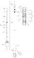
따라서, 최근에는 스텐트를 시술하는 비수술적인 치료방법이 제안되고 있는 바, 스텐트를 시술하기 위한 스텐트 시술장치의 한 예로서 도 1 및 도 2에 도면부호 201로 도시된 장치를 들 수 있다.Accordingly, in recent years, a non-surgical treatment method of stenting a stent has been proposed. As an example of the stent treatment device for stent treatment, the device shown in FIG. 1 and FIG.
이 스텐트 시술장치(201)는 도시된 것처럼, 내부에 배치된 고정관(231)과 그 외측에 끼워지는 이동관(233)으로 이루어지며, 고정관(231)의 선단 측에서 이동관(233)과의 사이에 스텐트(S)를 장전하여 운반하도록 되어 있다.As shown in the drawing, the
이를 위해 고정관(231)은 도시된 것처럼, 그 선단에 유선형의 안내팁(243)이 형성되어 있고, 안내팁(243) 바로 뒤쪽의 선단 측에 스텐트(S)를 장전하기 위한 스텐트 시트(241)가 축경되어 형성되며, 후단 측에 파지용 고정 손잡이(미도시)가 부착된다. 또한 이동관(233)은 도 1에 도시된 것처럼 안내팁(243)의 후단에 접촉하여 내부를 밀봉할 때까지 고정관(231) 위를 미끄럼 이동하도록 삽입되는 바, 중공의 관체로 되어 있으며, 후단 측에 파지용 이동 손잡이(미도시)가 부착된다.A
따라서, 종래의 스텐트 시술장치(201)에 의해 스텐트(S)를 시술하고자 하는 때는, 먼저 도 1에 도시된 바와 같이 이동관(233)이 화살표 방향으로 고정관(231)의 걸림턱(247)까지 밀착된 밀봉 상태에서 시술장치(201)를 혈관(V)과 같은 관상 조직 안으로 밀어 넣어 내부에 장전된 스텐트(S)가 병변부위에 정확히 위치하도록 한다.Therefore, when the stent S is to be operated by the
그 다음, 이동관(233)을 도 2의 화살표 방향으로 당겨 고정관(231)에 대해 후방으로 상대 이동시키면, 스텐트 시트(241)가 개방되면서 이 시트(241)에 장전되어 있던 스텐트(S)가 자체의 탄력으로 확장되면서 시트(241)로부터 이탈되어 병변부위를 바깥쪽으로 압박하게 되고, 이에 따라 병변부위로 막혀 있던 혈관(V)의 내강을 확장함으로써 스텐트(S) 시술이 종료된다.When the
그런데, 위와 같은 종래의 스텐트 시술장치(201)에 의해 도 2에 도시된 것처럼 스텐트(S)를 시술하게 되면, 일정 시간 경과 후 스텐트(S)에 의해 밖으로 밀려 있던 병변부위의 조직이 스텐트(S)의 메시 사이로 자라 나와 병변부위에 재협착을 일으키는 문제점이 있었다.2, after the lapse of a predetermined time, the tissue at the lesion portion pushed out by the stent S is stented by the stent S (FIG. 2) ), And there was a problem of causing restenosis at the lesion site.
이러한 문제를 해결하기 위해, 소작 전극장치로 병변부위를 소작하여 괴사시키는 예비 시술을 시행한 뒤, 스텐트(S)를 시술함으로써 위와 같은 재협착을 방지하고자 하였으나, 이를 위해서는 소작 전극장치의 전극침을 혈관 내에 투입, 제거하는 예비 시술을 시행하여야 하는 바, 예비 시술이 시행되는 만큼 환자나 시술자 모두에게 부담을 증대시키고, 시술 비용을 배가시키는 등 시술의 효율성이 크게 저하되는 문제점이 있었다.In order to solve this problem, a pretreatment for cauterization and necrosis of a lesion site with a cauterization electrode device was performed and then a stent (S) was used to prevent the restenosis. It is necessary to perform preliminary procedures to inject or remove blood into the blood vessels. As a result of the preliminary operation, there is a problem in that the efficiency of the procedure is greatly reduced, such as increasing the burden on the patient or the practitioner and doubling the operation cost.
본 발명은 위와 같은 종래의 문제점을 해결하기 위하여 안출된 것으로, 스텐트 시술 전에 병변부위를 소작하는 예비 시술과 소작되어 괴사된 병변부위에 스텐트를 시술하는 본 시술을 하나의 장치에 의해 시행함으로써, 스텐트 시술 후에 병변부위에 재협착이 발생하는 것을 방지하는 것은 물론이고, 예비 시술과 본 시술을 중복적으로 시행함에 따른 시술 상의 비효율을 제거하는 것을 그 목적으로 한다.SUMMARY OF THE INVENTION [0006] The present invention has been conceived in order to solve the above problems, and it is an object of the present invention to provide a stent for a stent, The object of the present invention is to prevent the restenosis from occurring in the lesion site after the procedure, and to eliminate the inefficiency in the procedure due to the duplication of the preliminary procedure and the present procedure.
위와 같은 목적을 달성하기 위해 본 발명은 복수의 관부재에 의해 관상 조직의 병변부위로 스텐트를 운반하여 시술하는 스텐트 시술장치에 있어서, 상기 관부재의 시술단에 형성되어, 상기 병변부위를 소작하는 소작용 바이폴라 전극; 및 상기 소작용 바이폴라 전극에 접속되어 상기 소작용 바이폴라 전극에서 고주파 전류가 방사되도록 하는 고주파 발생기;를 포함하고, 상기 소작용 바이폴라 전극은, 상기 관부재의 시술단 외주면 일측에 나선형으로 복수 회 감긴 액티브 전극과, 상기 액티브 전극 사이로 나선형으로 복수 회 감긴 패시브 전극을 포함하며, 상기 액티브 전극과 상기 패시브 전극은 상호 간에 일정한 교대 간격을 두고 상기 관부재의 시술단 외주면에 나선방향으로 경사지게 감겨 있는 것을 특징으로 하는 소작 겸용 스텐트 시술장치를 제공한다.In order to accomplish the above object, the present invention provides a stenting apparatus for performing a stent carrying a stent to a lesion portion of a coronary tissue by a plurality of tubular members, the stent treating apparatus comprising: A small bipolar electrode; And a high-frequency generator connected to the small-bipolar electrode to emit a high-frequency current from the small-bipolar electrode, wherein the small-bipolar electrode has a plurality of active portions wound spirally on one side of the outer peripheral surface of the tubular member, Wherein the active electrode and the passive electrode are wound on the outer circumferential surface of the tubular member at a predetermined alternate interval in an inclined manner in a spiral direction, The present invention provides a cautery-combined stent treatment device.
상기 관부재는, 일단에 파지를 위한 고정 손잡이가 부착되며, 타단에 스텐트 안착을 위한 스텐트 시트가 형성된 적어도 하나의 고정관; 및 일단에 파지를 위한 이동 손잡이가 부착되며, 상기 고정관 외주면에 길이방향으로 이동 가능하게 삽입되어, 상기 스텐트 시트에서 상기 고정관과의 사이에 상기 스텐트를 압축 상태로 장전하도록 되어 있는 적어도 하나의 이동관;을 포함하여 이루어지되, 상기 소작용 바이폴라 전극은 상기 고정관 또는 상기 이동관의 상기 고정 또는 이동 손잡이와 대응하는 시술단 일측에 배치되는 것이 바람직하다.Wherein the tubular member includes at least one fixing tube having a fixing handle for holding at one end and a stent sheet for seating the stent at the other end; And at least one moving tube having a moving handle for gripping at one end and being inserted into the outer circumferential surface of the stationary tube in a longitudinal direction so as to load the stent in a compressed state between the stationary tube and the stent sheet; The bipolar bipolar electrode is preferably disposed on one side of the treatment tube corresponding to the fixed or moving handle of the fixed tube or the movable tube.
상기 이동관은 소작 전, 소작 중, 또는 소작 후 조직의 온도를 모니터링하도록, 상기 소작용 바이폴라 전극에 의해 소작이 이루어지는 부분에 설치된 온도센서를 더 포함하는 것이 바람직하다.Preferably, the moving tube further includes a temperature sensor provided at a portion where cauterization is performed by the small-bipolar electrode so as to monitor the temperature of the tissue after the cauterization, cauterization, or cauterization.
삭제delete
삭제delete
삭제delete
삭제delete
삭제delete
삭제delete
상기 액티브 전극 또는 상기 패시브 전극 중 어느 한 쪽 전극은 다른 한 쪽 전극과 교대되지 않고 연속해서 중첩된 집중부를 포함하되, 상기 집중부는 상기 전극이 상기 교대 간격보다 조밀한 연속 간격 또는 무 간격으로 상기 고정관 또는 상기 이동관의 외주면에 감겨 있는 것이 바람직하다.Wherein at least one of the active electrode and the passive electrode includes a concentrated portion successively overlapped without being alternated with the other electrode, Or on the outer peripheral surface of the moving tube.
상기 어느 한 쪽 전극의 상기 집중부는 대응하는 다른 한 쪽 전극의 집중부와의 사이에 절연 틈새를 두고 있는 것이 바람직하다.It is preferable that the central portion of one of the electrodes has an insulating gap between the central portion and the corresponding central portion of the other electrode.
상기 절연 틈새에 대응하는 상기 고정관 또는 상기 이동관의 외주면에는 절연부가 형성되는 것이 바람직하다.And an insulating portion is formed on an outer circumferential surface of the fixed pipe or the moving pipe corresponding to the insulation gap.
상기 소작용 바이폴라 전극은 상기 이동 손잡이를 통해 상기 고주파 발생기로 이어진 인입선이 상기 액티브 전극 및 상기 패시브 전극의 연장선으로 형성되며, 상기 인입선은 상기 이동관 위에 코팅되는 피복부에 의해 외부로 노출되지 않도록 마감 처리되는 것이 바람직하다.Wherein the firing bipolar electrode is formed by an extension line of the active electrode and the passive electrode extending from the high frequency generator to the high frequency generator via the moving knob and the lead line is subjected to finishing treatment so as not to be exposed to the outside by the covering portion coated on the moving pipe .
따라서, 본 발명의 소작 겸용 스텐트 시술장치에 의하면, 변병부위에 스텐트를 시술하기 전 또는 후에 스텐트가 장전된 이동관 선단의 바이폴라 전극에 의해 병변부위를 소작하여 괴사시킬 수 있게 되므로, 스텐트가 시술된 병변부위에서 재협착이 발생하는 것을 방지할 수 있게 된다.Therefore, according to the cauterization stent operating apparatus of the present invention, since the lesion site can be cauterized and necrosed by the bipolar electrode at the distal end of the moving tube loaded with the stent before or after the stent is inserted into the lesion site, It is possible to prevent the occurrence of restenosis at the site.
뿐만 아니라, 하나의 스텐트 시술장치에 의해 스텐트 시술과 시술부위 소작을 한꺼번에 시행할 수 있게 되므로, 스텐트 시술장치의 삽입동작과 소작 전극의 삽입동작을 중복하여 실행하지 않아도 되며, 따라서 시술을 받는 환자나 시술을 수행하는 시술자 모두의 부담을 경감할 수 있게 되고, 아울러 시술 비용을 낮출 수 있게 되는 등 시술 효율성을 일층 향상시킬 수 있게 된다.In addition, since the stent procedure and the procedure site cautery can be performed all at once by the single stent procedure device, the insertion operation of the stent treatment device and the insertion operation of the cauterization electrode are not required to be performed in duplicate, The burden of all the practitioners performing the procedure can be reduced, and the cost of the operation can be lowered. Thus, the efficiency of the operation can be further improved.
도 1은 종래의 스텐트 시술장치를 스텐트 시술 전 상태로 도시한 정단면도.
도 2는 도 1을 스텐트 시술 후 상태로 도시한 정단면도.
도 3은 본 발명의 제1 실시예에 따른 스텐트 시술장치를 스텐트 시술 전 상태로 도시한 정단면도.
도 4는 도 3의 분해도.
도 5a 내지 도 5c는 도 3에 도시된 스텐트 시술장치의 변형예를 보인 도면.
도 6은 도 3을 스텐트 시술 후 상태로 도시한 정단면도.
도 7은 본 발명의 제2 실시예에 따른 스텐트 시술장치를 스텐트 시술 전 상태로 도시한 정단면도.
도 8은 도 7의 분해도.
도 9 및 도 10은 도 7에 도시된 스텐트 시술장치의 변형예를 보인 도면.
도 11은 도 7에 도시된 이동관의 횡단면도.
도 12는 본 발명의 제2 실시예에 따른 스텐트 시술장치를 스텐트 시술 후 상태로 도시한 정단면도.BRIEF DESCRIPTION OF THE DRAWINGS FIG. 1 is a front sectional view of a conventional stent-implanting device in a state before stent implantation; FIG.
Fig. 2 is a front sectional view of the stent of Fig. 1 after stent implantation; Fig.
FIG. 3 is a front sectional view of the stent-operating device according to the first embodiment of the present invention in a state before stenting. FIG.
4 is an exploded view of Fig.
5A to 5C are views showing a modification of the stent-operating device shown in Fig. 3; Fig.
Fig. 6 is a front sectional view of the stent shown in Fig. 3; Fig.
FIG. 7 is a front sectional view of a stenting device according to a second embodiment of the present invention in a state before stenting. FIG.
8 is an exploded view of Fig.
Figs. 9 and 10 are views showing a modification of the stent-operating device shown in Fig. 7. Fig.
11 is a cross-sectional view of the moving tube shown in Fig.
FIG. 12 is a front sectional view of a stenting device according to a second embodiment of the present invention, after stenting. FIG.
이하, 본 발명의 일 실시예에 따른 소작 겸용 스텐트 시술장치를 첨부도면을 참조하여 설명한다.BEST MODE FOR CARRYING OUT THE INVENTION Hereinafter, a cauterized stent treatment device according to an embodiment of the present invention will be described with reference to the accompanying drawings.
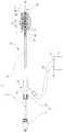
본 발명의 일 실시예에 따른 스텐트 시술장치는 혈관(V)과 같은 관상 조직의 병변부위로 스텐트(S)를 운반하여 시술하는 바, 도 3에 도면부호 1로 도시된 바와 같이, 크게 복수의 관부재(3)와 손잡이(5)로 이루어지며, 특히 소작용 바이폴라 전극(7)과 고주파 발생기(9)를 포함한다.The stent delivery device according to an embodiment of the present invention is carried out by delivering a stent S to a lesion site of a coronary tissue such as a blood vessel V. As shown by reference numeral 1 in FIG. 3, A bipolar electrode 7 and a high-
먼저, 상기 관부재(3)는 스텐트 시술장치(1)의 몸체를 이루는 중공 또는 중실의 관형 부재로서, 스텐트(S)를 장착하여 혈관(V)과 같은 관상 조직 안으로 운반하기 위해 복수의 관(31,33)으로 구성되는 바, 관(31,33)의 형태나 개수 등은 시술장치(1)의 용도나 크기에 따라 다양하게 변화될 수 있으나, 본 실시예에서는 도 3에 도시된 것처럼 고정관(31)과 이동관(33)으로 이루어진다.The
여기에서, 상기 고정관(31)은 스텐트 시술장치(1)의 기초가 되는 부분으로, 도 4에 도시된 바와 같이, 혈관(V)을 따라 이동할 수 있도록 PC 등의 연성 재질로 된 관체(35)와, 이 관체(35)의 후단에 결합되어 강성이 높은 SUS 등의 금속 재질로 된 푸셔(37), 그리고 관체(35)의 선단 즉, 시술단에 결합되되 선단에 유선형의 안내팁(43)이 형성된 스텐트 와이어(39)의 세 부분으로 이루어진다. 이때, 푸셔(37)는 시술 시 파지를 위해 후단에 고정 손잡이(5)가 부착되어 있으며, 휨없이 이동 손잡이(5)를 빼낼 수 있도록 즉, 이동 손잡이(5)가 뒤쪽으로 당겨질 때 이동 손잡이(5) 안으로 휘지 않고 상대 이동하여 들어갈 수 있도록 되어 있다. 또, 스텐트 와이어(39)는 도 3에 도시된 바와 같이, 이동관(33)과의 사이에 스텐트(S) 장전 공간을 확보하도록 직경이 축소되어 스텐트 시트(41)를 형성한다. 이때, 스텐트 와이어(39)는 시술 시 스텐트(S)의 장전위치를 확인할 수 있도록 스텐트 시트(41)의 선후 양단에 X-레이 표시부(45)가 구비된다.The
한편, 고정관(31)은 도면에 의해 구체화되어 있지 않지만, 후술하는 바이폴라 전극(7)을 선단 부분 즉, 시술단 일측에 즉, 예컨대 스텐트 와이어(39) 외주면에 구비할 수도 있다.On the other hand, although the
상기 이동관(33)은 고정관(31)에 장전된 스텐트(S)를 원하는 위치에서 개방하는 수단으로서, 도 3 및 도 6에서 알 수 있듯이, 스텐트 시트(41)에 안착되어 고정관(31)과의 사이에 압축 상태로 장전된 스텐트(S)를 개방하여 병변부위에 시술할 수 있도록, 고정관(31)의 외주면에 길이방향으로 상대 이동 가능하게 삽입된다. 따라서, 이동관(33)은 도 3 및 도 4에 도시된 바와 같이, 중공의 관 형태로 되어 있으며, 시술 시 파지를 위한 이동 손잡이(5)가 후단에 부착되고, 선단에 위치 확인을 위한 X-레이 표시부(46)가 감겨 있다, 또한, 이동관(33)은 선단 측에 후술하는 소작용 바이폴라 전극(7)과 이 바이폴라 전극(7)의 온도를 확인하기 위한 온도센서(47)가 배치되는 바, 이 바이폴라 전극(7)과 온도센서(47)에 연결된 인입선(49)들이 고정관(31)에 대한 상대 이동을 방해하지 않도록 하기 위해, 내측에 배선관(48)이 끼워지는 이중 구조로 마감된다.The moving
이때, 온도센서(47)는 소작이 이루어지는 이동관(33)의 전극(7) 부분에 위치하여, 소작 전, 소작 중, 또는 소작 후에 조직의 온도를 실시간으로 모니터링할 수 있는데, 소작 중에 측정되는 온도값은 소작 정도를 파악할 수 있도록 해주는 정보로서, 이를 통해 발열범위가 병변부위를 넘어 정상 조직을 소작하여 손상시키는 현상과, 발열범위가 병변부위에 못 미쳐 병변부위를 완벽히 소작하지 못하는 현상 등을 예방할 수 있게 된다.At this time, the
한편, 상기 손잡이(5)는 상술한 것처럼, 스텐트 시술장치(1)에 의한 스텐트(S) 시술 시 관부재(3)를 파지하는 수단으로서, 도 3 및 도 4에 도시된 바와 같이, 고정관(31)의 후단에 부착된 고정 손잡이(5)와 이동관(33)의 후단에 부착된 이동 손잡이(5)로 이루어지는데, 이때 고정 손잡이(5)는 시술장치(1) 전체를 혈관(V) 안으로 밀어 넣거나 빼기 위해 파지할 때 사용되며, 이동 손잡이(5)는 도 6에 도시된 것처럼 이동관(33)을 당겨 스텐트(S)를 병변부위에 시술할 때 사용된다. 특히, 이동 손잡이(5)는 도 3에 도시된 것처럼 혈관(V)으로 세척수 등을 급수하고, 관부재(3) 안으로 유입된 혈액 등을 빼내기 위한 급배수관(55)이 일측에 형성되고, 바이폴라 전극(7)과 온도센서(47)로 이어진 인입선을 관부재(3) 밖으로 빼내기 위한 인입관(56)이 타측에 형성된다.3 and 4, the
한편, 상기 고주파 발생기(9)는 고주파 교류를 발생시키는 장치로서, 일반적인 전기적 시술에 널리 사용되는 바, 아래에 설명되는 바와 같이, 양극과 음극 단자에 소작용 바이폴라 전극(7)의 액티브 전극(71) 또는 패시브 전극(73)을 선택적으로 접속하여, 소작용 바이폴라 전극(7)에 고주파 교류를 공급하도록 되어 있다.The
또한, 상기 소작용 바이폴라 전극(7)은 혈관(V) 등의 병변부위에 스텐트(S)를 시술하기 전에 또는 시술한 후에 병변부위를 소작하는 통전체로서, 도 3 및 도 4에 도시된 바와 같이, 관부재(3)에 즉, 본 실시예에서는 이동 손잡이(5)와 대향한 이동관(33) 선단의 시술단에 띠 형태로 감겨 형성되는 바, 적어도 하나의 절연 틈새(61)를 두고 상호 이격된 적어도 한 쌍의 액티브 전극(71)과 패시브 전극(73)으로 이루어진다. 이 액티브 전극(71)과 패시브 전극(73)은 각각의 인입선(49)에 연결된 전극선(63)을 통하여 고주파 발생기(9)의 액티브 및 패시브 단자(65,66)에 전기적으로 연결되며, 길이방향으로 서로 번갈아 배열되어 짝을 이루는 대응 전극(71,73) 사이에서 고주파 에너지를 방사하도록 되어 있다.The small-bipolar electrode 7 is a barrel which cauterizes a lesion site before or after a stent S is implanted in a lesion site such as a blood vessel (V), as shown in Figs. 3 and 4 In this embodiment, the
이때, 액티브 전극(71)과 패시브 전극(73) 사이의 절연틈새(61)와 대응하는 이동관(33)의 외주면에 절연부(62)를 감아 부착하는 경우에도 액티브 전극(71)과 패시브 전극(73)에서의 고주파 에너지 방사 효율을 높일 수 있게 되며, 절연부(62)로는 테프론이나 합성수지 등의 연성 재질을 사용하는 것이 바람직하다.At this time, when the insulating
또한, 액티브 전극(71)과 패시브 전극(73)은 다양한 형태 및 크기로 구현될 수 있는데, 도 4 및 도 5a에 도시된 바와 같이, 대응하는 한 쌍의 액티브 전극(71)과 패시브 전극(73)이 동일한 표면적을 갖는 대칭 구조로 되어 있는 경우, 타원으로 표시된 것처럼 전극(71,73) 전체에서 소작이 이루어지나, 도 5b 및 도 5c에 도시된 것처럼 액티브 전극(71)과 패시브 전극(73)의 표면적이 서로 달라 비대칭일 때, 표면적이 상대적으로 작은 액티브 전극(71) 또는 패시브 전극(73)으로 치우쳐서 소작이 이루어진다. 따라서, 전극(71,73)의 표면적 비율을 적절히 선택함으로써, 도 5b와 같이 패시브 전극(73)을 중심으로, 또는 도 5c와 같이 액티브 전극(71)을 중심으로 소작이 이루어지게 하는 등, 소작 범위와 형태, 속도 등을 쉽게 조절할 수 있게 된다.The
본 발명의 다른 실시예에 따른 소작 겸용 스텐트 시술장치는 도 7에 도면부호 101로 도시된 바와 같이, 도 3에 도시된 제1 실시예의 스텐트 시술장치와 마찬가지로 복수의 관부재(3)와 손잡이(5)로 이루어지며, 소작용 바이폴라 전극(107)과 고주파 발생기(9)를 포함하여 이루어진다.As shown by
여기에서, 상기 관부재(3)와 손잡이(5) 그리고 고주파 발생기(9)는 모두 위에서 설명한 제1 실시예의 그것과 동일하므로, 그 설명을 생략한다.Here, the
다만, 소작용 바이폴라 전극(107)은 제1 실시예의 전극(7)과 달리 도 7 및 도 8에 도시된 것처럼, 이동관(33)의 외주면 상에 교대로 감기는 액티브 전극(171) 및 패시브 전극(173)으로 이루어지는 바, 각각의 전극(171,173)은 이동관(33)의 외주면 선단 부위에서 후방으로 나선방향으로 경사지게 권취된다. 이때, 두 전극(171,173)은 동일한 리드각으로 나란하게 2회 이상 복수 회로 감겨 형성된다.7 and 8, unlike the electrode 7 of the first embodiment, the firing
이 중에서, 액티브 전극(171)은 도시된 것처럼, 타단이 전극선(63)을 통해 고주파 발생기(9)의 액티브 단자(65)에 연결되고, 패시브 전극(173)은 그 타단이 전극선(63)를 통해 고주파 발생기(9)의 패시브 단자(66)에 연결된다. 이때, 액티브 단자(65) 또는 패시브 단자(66)는 선택에 따라 양극이 될 수도 또는 음극이 될 수도 있다. 특히, 소작용 바이폴라 전극(107)은 도 7 및 도 8에 도시된 것처럼 나선방향으로 감긴 액티브 전극(171)의 사이로 패시브 전극(173)도 경사지게 권취되는 바, 상호 간에 간격을 유지함으로써 고주파 방사 시 각 전극(171,173)의 피치(P) 중간지점을 중심으로 발열이 시작되는데, 이때, 이동관(33)의 직경에 비해 피치(P)가 짧기 때문에 발열범위 즉, 소작이 이루어지는 범위는 이동관(33)을 둘러싸는 통모양으로 형성되며, 보다 바람직하게, 전극(171,173) 간 피치(P)가 도시된 것처럼 일정하다면 즉, 전극(171,173) 간 교대 간격이 일정하다면, 발열범위는 종단면 직사각형의 원통 모양이 된다.The other end of the
또한, 본 발명의 또 다른 실시 형태로서, 소작용 바이폴라 전극(107)은 도 9 및 도 10에 도시된 바와 같이, 액티브 전극(171)과 패시브 전극(173)에 일대일로 대응시켜 하나 이상의 집중부(175,177)를 형성할 수 있다. 액티브 전극(171)과 패시브 전극(173) 각각의 집중부(175,177)는 도시된 것처럼 패시브 전극(173) 또는 액티브 전극(171)의 상호 대응하는 위치에 형성되는 바, 전극(171,173)의 다른 부분과는 달리 한 쪽 전극이 다른 쪽 전극과 교대되지 않고 연속해서 권취된다.9 and 10, the firing
이때, 각각의 집중부(175,177)는 고주파 에너지의 방출 밀도를 높이기 위해 도 9 및 도 10에 도시된 것처럼 전극(171,173) 피치(PC)의 간격이 전극(171,173)의 다른 부분이 가진 피치(P)보다 조밀하게 되어 있거나 바람직하게는, 피치간격 없이 즉, 무간격으로 이동관(33) 외주면에 감긴다.In order to increase the emission density of high-frequency energy, the concentration of the pitches PC of the
위와 같이, 각각의 집중부(175,177)는 권선의 피치(PC)가 짧거나 없기 때문에 하나의 권선체로 볼 수 있고, 따라서 도 9에 도시된 바와 같이, 또 다른 실시 형태로서 대응하는 집중부(177,175)의 사이에 절연 틈새(161)를 확보함으로써, 고주파 방사 효율을 높일 수 있다.As described above, each of the concentrating
또 다른 실시 형태로서 대응하는 집중부(175,177) 사이 즉, 절연 틈새의 이동관(33) 외주면에 도 10에 도시된 것처럼, 절연부(23)를 형성하는 경우에는 대응하는 집중부(175,177) 사이의 절연 틈새(161)를 도 9와 같이 충분하게 확보하지 않아도, 절연부(162)에 의해 절연성능을 유지할 수 있으며, 따라서 마찬가지로 고주파 방사 효율을 높일 수 있게 된다.As another embodiment, in the case where the insulating portion 23 is formed between the corresponding concentrating
한편, 액티브 전극(171)과 패시브 전극(173)은 이동관(33)의 후단에 일체로 형성되는 이동 손잡이(5)를 통해 고주파 발생기(9)로 이어진 전극선(63)과 연결되는 바, 전극(171,173)으로부터 별도의 배선관(48)을 통해 인입선(49)을 빼내는 제1 실시예와는 달리, 전극(171,173)을 그대로 인입선(49)으로 사용하는 형태로서, 도 11에 도시된 것처럼 이동관(33)을 바깥쪽의 외피부(57)와 안쪽의 내피부(58)로 구성하고 내피부(58) 외주면에 교대로 감기는 전극(171,173)을 그대로 이동 손잡이(5)까지 연장하여 외피부(57)로 코팅함으로써 전극으로 사용되는 선단 부분만 외부로 노출되고, 인입선(49)으로 사용되는 나머지 부분은 외피부(57)에 의해 외부로 노출되지 않고 마감 처리되도록 한다.The
이제, 위와 같이 구성되는 본 발명에 따른 소작 겸용 스텐트 시술장치(1)의 작용을 설명하면 다음과 같다.Hereinafter, the operation of the cauterization stent treatment device 1 according to the present invention constructed as above will be described.
본 발명의 제1 실시예에 따른 스텐트 시술장치(1)에 의해 스텐트(S) 시술을 하는 경우, 도 3에 도시된 것처럼 먼저 시술장치(1)를 혈관(V) 등의 병변부위에 위치시킨다. 이때, 이동관(33)의 선단에 부착된 X-레이 표시부(46)에 의해 소작용 바이폴라 전극(7)을 병변부위의 중앙에 오도록 정확히 맞춘다.When the stent S is performed by the stenting apparatus 1 according to the first embodiment of the present invention, as shown in Fig. 3, the treating apparatus 1 is first positioned at the lesion site of the blood vessel V or the like . At this time, the
그 다음, 고주파 발생기(9)를 작동하여 액티브 전극(71)과 패시브 전극(73)을 통해 고주파의 전류를 방사시키면, 도 3에 타원으로 표시된 고주파 에너지 방사 구역에서 발생되는 에너지에 의해 병변부위 조직의 이온이 진동을 일으켜 마찰열을 발생시킴으로써 열에 의해 소작된다.Then, when a high frequency current is radiated through the
그리고 나서, 고정관(31)의 위치를 고정한 채로, 이동관(33)을 상대 이동시키면, 도 6에 도시된 것처럼, 고정관(31) 선단의 스텐트 시트(41)에 장전되어 있던 스텐트(S)가 자체 탄력에 의해 확장되어 혈관(V)에 밀착되는데, 이때 스텐트(S) 시술 위치도 스텐트 시트(41) 양단의 X-레이 표시부에 의해 확인할 수 있다. 이렇게 해서 시술이 완료된 스텐트(S)는 병변부위를 밀어내 혈관(V) 내강의 구경이 확보될 수 있도록 한다.6, the stent S loaded on the
한편, 제2 실시예에 따른 스텐트 시술장치(101)에 의해 스텐트(S)를 시술하는 경우에도 마찬가지로, 도 7에 도시된 바와 같이, 먼저 시술장치(101)를 X-레이 표시부(46)에 의해 혈관(V) 등의 병변부위에 정확하게 위치시킨다.On the other hand, when the stent S is to be implanted by the
그 다음, 고주파 발생기(9)를 작동시키면 액티브 전극(71)과 패시브 전극(73) 사이에서 고주파의 교류전류가 방사되는데, 이때, 액티브 전극(71)과 패시브 전극(73)은 도 7에 도시된 것처럼, 피치(P) 간격으로 인접한 전극과 전극 사이마다 고주파 에너지 방사가 이루어져 전체적으로 원통형으로 고주파 에너지 방사 구역이 형성되고, 이 방사 구역에서 발생되는 열에 의해 병변부위가 소작되는데, 이때 혈관(V) 등 관상 기관의 병변부위는 병변부위의 형태를 추종하는 원통형의 방사 구역에 의해서 최소 두께로 즉, 다른 인접 조직의 손상이 없도록 효과적 소작된다.Next, when the
또한, 본 발명의 또 다른 실시 형태로서, 도 9 및 도 10에 도시된 바와 같이, 전극(171,173)에 의해 원통형의 즉, 종단면 직사각형의 발열범위가 형성되고, 거기에 추가로 집중부(175,177)에 의해 절연 틈새(161) 또는 절연부(162)를 중심으로 타원 구형의 즉, 종단면 타원형의 발열범위가 대응하는 집중부(175,177) 쌍의 수에 따라 하나 이상 형성되므로, 관상을 벗어나 넓게 분포하는 부위를 가진 병변에 대해서도 즉, 예를 들어, 혈관과 같은 관상 조직에 종방향 상으로 전체적으로 분포하면서도 특정 위치에 혈관의 반경방향으로 넓게 퍼진 병변부위가 발생한 경우에도, 집중부(175,177)를 반경방향으로 넓게 분포한 병변부위에 맞춤으로써, 효과적으로 소작을 실시할 수 있게 된다.9 and 10, the
그리고 나서, 제1 실시예에서와 마찬가지로, 고정관(31)의 위치를 고정한 채로, 이동관(33)을 상대 이동시켜, 도 12에 도시된 것처럼, 스텐트 시트(41)에 장전되어 있던 스텐트(S)가 자체 탄력에 의해 확장되어 소작된 병변부위에 밀착되도록 하면, 스텐트(S) 시술이 종료된다.12, the stent S loaded on the
1 : 소작 겸용 스텐트 시술장치 3 : 관부재
5 : 손잡이 7 : 바이폴라 전극
9 : 고주파 발생기 31 : 고정관
33 : 이동관 37 : 푸셔
39 : 스텐트 와이어 41 : 스텐트 시트
43 : 안내팁 45, 46 : X-레이 표시부
47 : 온도센서 51 : 고정 손잡이
53 : 이동 손잡이 66 : 전극선
71 : 액티브 전극 73 : 패시브 전극
73 : 패시브 전극 175 : 액티브 집중부
177 : 패시브 집중부1: combined cautery stenting device 3: tubular member
5: handle 7: bipolar electrode
9: High frequency generator 31: Fixed tube
33: moving pipe 37: pusher
39: stent wire 41: stent sheet
43:
47: Temperature sensor 51: Fixed knob
53: shift knob 66: electrode line
71: active electrode 73: passive electrode
73: passive electrode 175: active concentrated portion
177: passive concentrating unit
Claims (13)
Translated fromKorean상기 관부재의 시술단에 형성되어, 상기 병변부위를 소작하는 소작용 바이폴라 전극; 및
상기 소작용 바이폴라 전극에 접속되어 상기 소작용 바이폴라 전극에서 고주파 전류가 방사되도록 하는 고주파 발생기;를 포함하고,
상기 소작용 바이폴라 전극은,
상기 관부재의 시술단 외주면 일측에 나선형으로 복수 회 감긴 액티브 전극과, 상기 액티브 전극 사이로 나선형으로 복수 회 감긴 패시브 전극을 포함하며,
상기 액티브 전극과 상기 패시브 전극은 상호 간에 일정한 교대 간격을 두고 상기 관부재의 시술단 외주면에 나선방향으로 경사지게 감겨 있는 것을 특징으로 하는 소작 겸용 스텐트 시술장치.A stenting device for performing a stent carrying a stent to a lesion portion of a coronary tissue by a plurality of tubular members,
A bipolar electrode formed on a distal end of the tubular member and cauterizing the lesion site; And
And a high-frequency generator connected to the small-bipolar electrode for allowing a high-frequency current to be radiated from the small-bipolar electrode,
The firing bipolar electrode may include:
An active electrode spirally wound a plurality of times on one side of the outer circumferential surface of the tubular member, and a passive electrode wound spirally a plurality of times between the active electrodes,
Wherein the active electrode and the passive electrode are wound on the outer circumferential surface of the tubular member at an alternating interval with each other in an inclined manner in a spiral direction.
상기 관부재는,
일단에 파지를 위한 고정 손잡이가 부착되며, 타단에 스텐트 안착을 위한 스텐트 시트가 형성된 적어도 하나의 고정관; 및
일단에 파지를 위한 이동 손잡이가 부착되며, 상기 고정관 외주면에 길이방향으로 이동 가능하게 삽입되어, 상기 스텐트 시트에서 상기 고정관과의 사이에 상기 스텐트를 압축 상태로 장전하도록 되어 있는 적어도 하나의 이동관;을 포함하여 이루어지되,
상기 소작용 바이폴라 전극은 상기 고정관 또는 상기 이동관의 상기 고정 또는 이동 손잡이와 대응하는 시술단 일측에 배치되는 것을 특징으로 하는 소작 겸용 스텐트 시술장치.The method according to claim 1,
Wherein the tube member comprises:
At least one fixing tube having a fixing handle for gripping at one end and a stent sheet for seating the stent at the other end; And
At least one moving tube to which a moving handle for gripping is attached at one end and is inserted into the outer circumferential surface of the stationary tube movably in the longitudinal direction so as to load the stent in a compressed state between the stationary tube and the stent sheet; , ≪ / RTI >
Wherein the firing bipolar electrode is disposed on one side of a treatment end corresponding to the fixed or moving handle of the fixed tube or the movable tube.
상기 이동관은 소작 전, 소작 중, 또는 소작 후 조직의 온도를 모니터링하도록, 상기 소작용 바이폴라 전극에 의해 소작이 이루어지는 부분에 설치된 온도센서를 더 포함하는 것을 특징으로 하는 소작 겸용 스텐트 시술장치.The method of claim 2,
Wherein the moving tube further comprises a temperature sensor provided at a portion where cauterization is performed by the small-bipolar electrode so as to monitor the temperature of the tissue after the cauterization, cauterization, or cauterization.
상기 액티브 전극 또는 상기 패시브 전극 중 어느 한 쪽 전극은 다른 한 쪽 전극과 교대되지 않고 연속해서 중첩된 집중부를 포함하되, 상기 집중부는 상기 전극이 상기 교대 간격보다 조밀한 연속 간격 또는 무 간격으로 상기 고정관 또는 상기 이동관의 외주면에 감겨 있는 것을 특징으로 하는 소작 겸용 스텐트 시술장치.The method of claim 2,
Wherein at least one of the active electrode and the passive electrode includes a concentrated portion successively overlapped without being alternated with the other electrode, Or the outer circumferential surface of the moving tube.
상기 어느 한 쪽 전극의 상기 집중부는 대응하는 다른 한 쪽 전극의 집중부와의 사이에 절연 틈새를 두고 있는 것을 특징으로 하는 소작 겸용 스텐트 시술장치.The method of claim 10,
Wherein the central portion of one of the electrodes has an insulation gap between the central portion of the other electrode and the corresponding central portion of the other electrode.
상기 절연 틈새에 대응하는 상기 고정관 또는 상기 이동관의 외주면에는 절연부가 형성되는 것을 특징으로 하는 소작 겸용 스텐트 시술장치.The method of claim 11,
Wherein an insulating portion is formed on an outer peripheral surface of the fixed pipe or the movable pipe corresponding to the insulation gap.
상기 소작용 바이폴라 전극은 상기 이동 손잡이를 통해 상기 고주파 발생기로 이어진 인입선이 상기 액티브 전극 및 상기 패시브 전극의 연장선으로 형성되며, 상기 인입선은 상기 이동관의 내피부와 외피부 사이에 개재되어 외부로 노출되지 않도록 마감 처리되는 것을 특징으로 하는 소작 겸용 스텐트 시술장치.
The method of claim 2,
And a lead line extending to the high frequency generator through the moving handle is formed as an extension line of the active electrode and the passive electrode, and the lead line is interposed between the inner and outer skin of the moving tube and is not exposed to the outside The stent being inserted into the stent.
Priority Applications (7)
| Application Number | Priority Date | Filing Date | Title |
|---|---|---|---|
| KR1020120053126AKR101415902B1 (en) | 2012-05-18 | 2012-05-18 | Catheter provided with cauterization system |
| ES13791710.0TES2684393T3 (en) | 2012-05-18 | 2013-05-10 | Combined stenting and stent placement device |
| PCT/KR2013/004141WO2013172599A1 (en) | 2012-05-18 | 2013-05-10 | Combined cauterization and stent operation device |
| EP13791710.0AEP2851024B1 (en) | 2012-05-18 | 2013-05-10 | Combined cauterization and stent operation device |
| US14/401,885US9770353B2 (en) | 2012-05-18 | 2013-05-10 | Combined cauterization and stent operation device |
| JP2015512571AJP5992607B2 (en) | 2012-05-18 | 2013-05-10 | Shochu combined stent treatment device |
| CN201380026011.0ACN104519837B (en) | 2012-05-18 | 2013-05-10 | Possesses the stent procedure device of cautery function |
Applications Claiming Priority (1)
| Application Number | Priority Date | Filing Date | Title |
|---|---|---|---|
| KR1020120053126AKR101415902B1 (en) | 2012-05-18 | 2012-05-18 | Catheter provided with cauterization system |
Publications (2)
| Publication Number | Publication Date |
|---|---|
| KR20130140954A KR20130140954A (en) | 2013-12-26 |
| KR101415902B1true KR101415902B1 (en) | 2014-07-08 |
Family
ID=49583959
Family Applications (1)
| Application Number | Title | Priority Date | Filing Date |
|---|---|---|---|
| KR1020120053126AActiveKR101415902B1 (en) | 2012-05-18 | 2012-05-18 | Catheter provided with cauterization system |
Country Status (7)
| Country | Link |
|---|---|
| US (1) | US9770353B2 (en) |
| EP (1) | EP2851024B1 (en) |
| JP (1) | JP5992607B2 (en) |
| KR (1) | KR101415902B1 (en) |
| CN (1) | CN104519837B (en) |
| ES (1) | ES2684393T3 (en) |
| WO (1) | WO2013172599A1 (en) |
Families Citing this family (11)
| Publication number | Priority date | Publication date | Assignee | Title |
|---|---|---|---|---|
| WO2017014333A1 (en)* | 2015-07-21 | 2017-01-26 | 주식회사 스타메드 | Bipolar electrode for radio frequency ablation |
| KR101781052B1 (en)* | 2016-02-15 | 2017-10-23 | (주) 태웅메디칼 | Electrocautery stent delivery system with a bi-polar tip |
| WO2017142236A1 (en)* | 2016-02-15 | 2017-08-24 | (주) 태웅메디칼 | Stent delivery system including anode-type electrical cautery tip |
| KR101963621B1 (en)* | 2016-11-04 | 2019-04-01 | 주식회사 스타메드 | Radiofrequency ablation device |
| KR101902781B1 (en) | 2016-11-16 | 2018-10-01 | (주) 태웅메디칼 | Electrocautery stent delivery system with a mono-polar tip |
| KR101976743B1 (en)* | 2017-07-14 | 2019-05-09 | 주식회사 비씨엠 | Stent insertion device for human digestive organ connection |
| CN110584852B (en)* | 2018-06-13 | 2025-07-11 | 南微医学科技股份有限公司 | Thermal puncture stent implanter |
| CN109700572B (en)* | 2018-12-29 | 2020-09-25 | 先健科技(深圳)有限公司 | Shrinkage stop device for conveyor and conveyor thereof |
| KR102323448B1 (en)* | 2019-12-19 | 2021-11-09 | 울산대학교 산학협력단 | Radiofrequency ablation instrument |
| KR102551847B1 (en)* | 2021-01-04 | 2023-07-06 | 재단법인 아산사회복지재단 | Electrode stent device using bipolar electrode |
| KR102665235B1 (en)* | 2021-10-28 | 2024-05-23 | 주식회사 바이오유닛 | Bipolar type medical electrode system |
Citations (4)
| Publication number | Priority date | Publication date | Assignee | Title |
|---|---|---|---|---|
| US5178618A (en) | 1991-01-16 | 1993-01-12 | Brigham And Womens Hospital | Method and device for recanalization of a body passageway |
| WO2005065559A1 (en) | 2004-01-06 | 2005-07-21 | Toray Industries, Inc. | Balloon catheter |
| US7209783B2 (en)* | 2001-06-15 | 2007-04-24 | Cardiac Pacemakers, Inc. | Ablation stent for treating atrial fibrillation |
| KR20090109283A (en)* | 2008-04-15 | 2009-10-20 | 중앙대학교 산학협력단 | Bipolar electrode guide wire and catheter system using same |
Family Cites Families (29)
| Publication number | Priority date | Publication date | Assignee | Title |
|---|---|---|---|---|
| US5749914A (en) | 1989-01-06 | 1998-05-12 | Advanced Coronary Intervention | Catheter for obstructed stent |
| US5545193A (en)* | 1993-10-15 | 1996-08-13 | Ep Technologies, Inc. | Helically wound radio-frequency emitting electrodes for creating lesions in body tissue |
| JPH0838503A (en)* | 1994-08-03 | 1996-02-13 | Clinical Supply:Kk | Catheter apparatus fitted wih gage-shaped electrode for ablation |
| US6030382A (en)* | 1994-08-08 | 2000-02-29 | Ep Technologies, Inc. | Flexible tissue ablatin elements for making long lesions |
| JPH09140807A (en) | 1995-11-21 | 1997-06-03 | Olympus Optical Co Ltd | Hyperthermia applicator |
| US5830179A (en) | 1996-04-09 | 1998-11-03 | Endocare, Inc. | Urological stent therapy system and method |
| US5921954A (en) | 1996-07-10 | 1999-07-13 | Mohr, Jr.; Lawrence G. | Treating aneurysms by applying hardening/softening agents to hardenable/softenable substances |
| US6014589A (en)* | 1997-11-12 | 2000-01-11 | Vnus Medical Technologies, Inc. | Catheter having expandable electrodes and adjustable stent |
| DE10102254A1 (en)* | 2001-01-19 | 2002-08-08 | Celon Ag Medical Instruments | Device for the electrothermal treatment of the human or animal body |
| US7285116B2 (en)* | 2004-05-15 | 2007-10-23 | Irvine Biomedical Inc. | Non-contact tissue ablation device and methods thereof |
| AU2002952318A0 (en)* | 2002-10-29 | 2002-11-14 | Advanced Metal Coatings Pty Limited | Production of lesions in a body |
| US7819866B2 (en)* | 2003-01-21 | 2010-10-26 | St. Jude Medical, Atrial Fibrillation Division, Inc. | Ablation catheter and electrode |
| JP4374345B2 (en)* | 2003-02-19 | 2009-12-02 | タエウォン メディカル カンパニー リミテッド | High frequency heat treatment stent |
| US20050049670A1 (en) | 2003-08-29 | 2005-03-03 | Jones Donald K. | Self-expanding stent and stent delivery system for treatment of vascular disease |
| US7867271B2 (en)* | 2003-11-20 | 2011-01-11 | Advanced Cardiovascular Systems, Inc. | Rapid-exchange delivery systems for self-expanding stents |
| JP2005192725A (en)* | 2004-01-06 | 2005-07-21 | Toray Ind Inc | Ablation catheter with balloon |
| JP5046931B2 (en)* | 2004-08-05 | 2012-10-10 | タイコ ヘルスケア グループ リミテッド パートナーシップ | Method and apparatus for coagulating and / or constricting hollow anatomical structures |
| JP4481880B2 (en) | 2005-06-03 | 2010-06-16 | オリンパスメディカルシステムズ株式会社 | Stent placement device |
| US20070055326A1 (en)* | 2005-07-21 | 2007-03-08 | Farley Brian E | Method of treating a hollow anatomical structure with a thermal catheter |
| GB0610637D0 (en)* | 2006-05-23 | 2006-07-05 | Emcision Ltd | Apparatus and method for treating tissue such as tumours |
| WO2007135437A1 (en)* | 2006-05-23 | 2007-11-29 | Emcision Limited | Apparatus and method for treating tissue such as tumours |
| GB0610489D0 (en)* | 2006-05-24 | 2006-07-05 | Emcision Ltd | Vessel closing device |
| US8007496B2 (en)* | 2006-05-26 | 2011-08-30 | Boston Scientific Scimed, Inc. | Method of therapeutically treating tissue while preventing perfusion/ventilation of the tissue |
| WO2008153357A2 (en)* | 2007-06-15 | 2008-12-18 | Chung-Ang University Industry-Academy Cooperation Foundation | Bipolar electrode type guide wire and catheter system |
| CN201244105Y (en)* | 2008-08-14 | 2009-05-27 | 浙江省中医院 | Imbedding device for stent secondary release with direct view under endoscope |
| CN102028570A (en)* | 2009-09-30 | 2011-04-27 | 吴雄 | Non-vessel stent conveyor capable of developing under surveillance of X rays |
| WO2011161474A1 (en)* | 2010-06-24 | 2011-12-29 | Emcision Limited | Enhanced ablation apparatus |
| CN102038565B (en) | 2010-12-17 | 2013-08-14 | 北京有色金属研究总院 | Great vascular stent delivery system |
| CN202113191U (en)* | 2011-04-07 | 2012-01-18 | 北京畅想天行医疗技术有限公司 | Duodenum-jejunum built-in cannula conveyor |
- 2012
- 2012-05-18KRKR1020120053126Apatent/KR101415902B1/enactiveActive
- 2013
- 2013-05-10USUS14/401,885patent/US9770353B2/enactiveActive
- 2013-05-10WOPCT/KR2013/004141patent/WO2013172599A1/enactiveApplication Filing
- 2013-05-10EPEP13791710.0Apatent/EP2851024B1/enactiveActive
- 2013-05-10ESES13791710.0Tpatent/ES2684393T3/enactiveActive
- 2013-05-10JPJP2015512571Apatent/JP5992607B2/enactiveActive
- 2013-05-10CNCN201380026011.0Apatent/CN104519837B/enactiveActive
Patent Citations (4)
| Publication number | Priority date | Publication date | Assignee | Title |
|---|---|---|---|---|
| US5178618A (en) | 1991-01-16 | 1993-01-12 | Brigham And Womens Hospital | Method and device for recanalization of a body passageway |
| US7209783B2 (en)* | 2001-06-15 | 2007-04-24 | Cardiac Pacemakers, Inc. | Ablation stent for treating atrial fibrillation |
| WO2005065559A1 (en) | 2004-01-06 | 2005-07-21 | Toray Industries, Inc. | Balloon catheter |
| KR20090109283A (en)* | 2008-04-15 | 2009-10-20 | 중앙대학교 산학협력단 | Bipolar electrode guide wire and catheter system using same |
Also Published As
| Publication number | Publication date |
|---|---|
| EP2851024A4 (en) | 2016-03-02 |
| ES2684393T3 (en) | 2018-10-02 |
| CN104519837B (en) | 2016-12-28 |
| EP2851024A1 (en) | 2015-03-25 |
| US20150133927A1 (en) | 2015-05-14 |
| EP2851024B1 (en) | 2018-08-01 |
| JP2015521065A (en) | 2015-07-27 |
| JP5992607B2 (en) | 2016-09-14 |
| KR20130140954A (en) | 2013-12-26 |
| WO2013172599A1 (en) | 2013-11-21 |
| CN104519837A (en) | 2015-04-15 |
| US9770353B2 (en) | 2017-09-26 |
Similar Documents
| Publication | Publication Date | Title |
|---|---|---|
| KR101415902B1 (en) | Catheter provided with cauterization system | |
| CN100522093C (en) | Electrode arrangement for a surgical instrument | |
| JP7749695B2 (en) | Circumferential ablation devices and methods | |
| US20100049191A1 (en) | Tissue ablator | |
| US20080097139A1 (en) | Systems and methods for treating lung tissue | |
| CN107847270A (en) | Steerable tissue mapping and ablation device | |
| JP2007531545A (en) | Biological tissue peeling device | |
| US20250160920A1 (en) | An electroporation device | |
| US20150018819A1 (en) | Medical device with stretchable electrode assemblies | |
| CN115348844A (en) | Pulsed electric field waveform operation and use | |
| KR101415900B1 (en) | Reiterating type bipolar electrode for high frequency thermotherapy | |
| USRE49433E1 (en) | Catheter for denervation | |
| US12059199B2 (en) | Stent delivery system comprising monopolar electrocautery tip | |
| JP2023175056A (en) | Medical device and shunt formation method | |
| US20250099170A1 (en) | Ablation Apparatus | |
| KR102583363B1 (en) | Irreversible electroporation device for endoscopy | |
| US11883092B2 (en) | Radiofrequency ablation catheter apparatus with meshed carrier having stabilized shape, system thereof and methods thereof | |
| KR102551847B1 (en) | Electrode stent device using bipolar electrode | |
| CN117241752A (en) | Circumferential ablation apparatus and method | |
| CN118785862A (en) | Electroporation device | |
| WO2025165983A1 (en) | Ablation catheter apparatuses and methods |
Legal Events
| Date | Code | Title | Description |
|---|---|---|---|
| A201 | Request for examination | ||
| PA0109 | Patent application | Patent event code:PA01091R01D Comment text:Patent Application Patent event date:20120518 | |
| PA0201 | Request for examination | ||
| E902 | Notification of reason for refusal | ||
| PE0902 | Notice of grounds for rejection | Comment text:Notification of reason for refusal Patent event date:20130912 Patent event code:PE09021S01D | |
| PG1501 | Laying open of application | ||
| E701 | Decision to grant or registration of patent right | ||
| PE0701 | Decision of registration | Patent event code:PE07011S01D Comment text:Decision to Grant Registration Patent event date:20140327 | |
| GRNT | Written decision to grant | ||
| PR0701 | Registration of establishment | Comment text:Registration of Establishment Patent event date:20140624 Patent event code:PR07011E01D | |
| PR1002 | Payment of registration fee | Payment date:20140625 End annual number:3 Start annual number:1 | |
| PG1601 | Publication of registration | ||
| FPAY | Annual fee payment | Payment date:20170612 Year of fee payment:4 | |
| PR1001 | Payment of annual fee | Payment date:20170612 Start annual number:4 End annual number:4 | |
| FPAY | Annual fee payment | Payment date:20190503 Year of fee payment:6 | |
| PR1001 | Payment of annual fee | Payment date:20190503 Start annual number:6 End annual number:6 | |
| PR1001 | Payment of annual fee | Payment date:20200513 Start annual number:7 End annual number:7 | |
| PR1001 | Payment of annual fee | Payment date:20230517 Start annual number:10 End annual number:10 | |
| PR1001 | Payment of annual fee | Payment date:20250429 Start annual number:12 End annual number:12 |