KR101415313B1 - Platform, device, system, and method for substrate processing and analysis - Google Patents
Platform, device, system, and method for substrate processing and analysisDownload PDFInfo
- Publication number
- KR101415313B1 KR101415313B1KR1020087022542AKR20087022542AKR101415313B1KR 101415313 B1KR101415313 B1KR 101415313B1KR 1020087022542 AKR1020087022542 AKR 1020087022542AKR 20087022542 AKR20087022542 AKR 20087022542AKR 101415313 B1KR101415313 B1KR 101415313B1
- Authority
- KR
- South Korea
- Prior art keywords
- coordinate system
- cylinder
- stage
- workpiece
- pattern
- Prior art date
- Legal status (The legal status is an assumption and is not a legal conclusion. Google has not performed a legal analysis and makes no representation as to the accuracy of the status listed.)
- Active
Links
Images


Classifications
- G—PHYSICS
- G03—PHOTOGRAPHY; CINEMATOGRAPHY; ANALOGOUS TECHNIQUES USING WAVES OTHER THAN OPTICAL WAVES; ELECTROGRAPHY; HOLOGRAPHY
- G03F—PHOTOMECHANICAL PRODUCTION OF TEXTURED OR PATTERNED SURFACES, e.g. FOR PRINTING, FOR PROCESSING OF SEMICONDUCTOR DEVICES; MATERIALS THEREFOR; ORIGINALS THEREFOR; APPARATUS SPECIALLY ADAPTED THEREFOR
- G03F7/00—Photomechanical, e.g. photolithographic, production of textured or patterned surfaces, e.g. printing surfaces; Materials therefor, e.g. comprising photoresists; Apparatus specially adapted therefor
- G03F7/70—Microphotolithographic exposure; Apparatus therefor
- G03F7/708—Construction of apparatus, e.g. environment aspects, hygiene aspects or materials
- G03F7/70858—Environment aspects, e.g. pressure of beam-path gas, temperature
- G—PHYSICS
- G03—PHOTOGRAPHY; CINEMATOGRAPHY; ANALOGOUS TECHNIQUES USING WAVES OTHER THAN OPTICAL WAVES; ELECTROGRAPHY; HOLOGRAPHY
- G03F—PHOTOMECHANICAL PRODUCTION OF TEXTURED OR PATTERNED SURFACES, e.g. FOR PRINTING, FOR PROCESSING OF SEMICONDUCTOR DEVICES; MATERIALS THEREFOR; ORIGINALS THEREFOR; APPARATUS SPECIALLY ADAPTED THEREFOR
- G03F7/00—Photomechanical, e.g. photolithographic, production of textured or patterned surfaces, e.g. printing surfaces; Materials therefor, e.g. comprising photoresists; Apparatus specially adapted therefor
- G03F7/70—Microphotolithographic exposure; Apparatus therefor
- G03F7/70216—Mask projection systems
- G03F7/70283—Mask effects on the imaging process
- G03F7/70291—Addressable masks, e.g. spatial light modulators [SLMs], digital micro-mirror devices [DMDs] or liquid crystal display [LCD] patterning devices
- G—PHYSICS
- G03—PHOTOGRAPHY; CINEMATOGRAPHY; ANALOGOUS TECHNIQUES USING WAVES OTHER THAN OPTICAL WAVES; ELECTROGRAPHY; HOLOGRAPHY
- G03F—PHOTOMECHANICAL PRODUCTION OF TEXTURED OR PATTERNED SURFACES, e.g. FOR PRINTING, FOR PROCESSING OF SEMICONDUCTOR DEVICES; MATERIALS THEREFOR; ORIGINALS THEREFOR; APPARATUS SPECIALLY ADAPTED THEREFOR
- G03F7/00—Photomechanical, e.g. photolithographic, production of textured or patterned surfaces, e.g. printing surfaces; Materials therefor, e.g. comprising photoresists; Apparatus specially adapted therefor
- G03F7/70—Microphotolithographic exposure; Apparatus therefor
- G03F7/70216—Mask projection systems
- G03F7/70358—Scanning exposure, i.e. relative movement of patterned beam and workpiece during imaging
- G03F7/70366—Rotary scanning
- G—PHYSICS
- G03—PHOTOGRAPHY; CINEMATOGRAPHY; ANALOGOUS TECHNIQUES USING WAVES OTHER THAN OPTICAL WAVES; ELECTROGRAPHY; HOLOGRAPHY
- G03F—PHOTOMECHANICAL PRODUCTION OF TEXTURED OR PATTERNED SURFACES, e.g. FOR PRINTING, FOR PROCESSING OF SEMICONDUCTOR DEVICES; MATERIALS THEREFOR; ORIGINALS THEREFOR; APPARATUS SPECIALLY ADAPTED THEREFOR
- G03F7/00—Photomechanical, e.g. photolithographic, production of textured or patterned surfaces, e.g. printing surfaces; Materials therefor, e.g. comprising photoresists; Apparatus specially adapted therefor
- G03F7/70—Microphotolithographic exposure; Apparatus therefor
- G03F7/70383—Direct write, i.e. pattern is written directly without the use of a mask by one or multiple beams
- G03F7/70391—Addressable array sources specially adapted to produce patterns, e.g. addressable LED arrays
- G—PHYSICS
- G03—PHOTOGRAPHY; CINEMATOGRAPHY; ANALOGOUS TECHNIQUES USING WAVES OTHER THAN OPTICAL WAVES; ELECTROGRAPHY; HOLOGRAPHY
- G03F—PHOTOMECHANICAL PRODUCTION OF TEXTURED OR PATTERNED SURFACES, e.g. FOR PRINTING, FOR PROCESSING OF SEMICONDUCTOR DEVICES; MATERIALS THEREFOR; ORIGINALS THEREFOR; APPARATUS SPECIALLY ADAPTED THEREFOR
- G03F7/00—Photomechanical, e.g. photolithographic, production of textured or patterned surfaces, e.g. printing surfaces; Materials therefor, e.g. comprising photoresists; Apparatus specially adapted therefor
- G03F7/70—Microphotolithographic exposure; Apparatus therefor
- G03F7/70383—Direct write, i.e. pattern is written directly without the use of a mask by one or multiple beams
- G03F7/704—Scanned exposure beam, e.g. raster-, rotary- and vector scanning
- G—PHYSICS
- G03—PHOTOGRAPHY; CINEMATOGRAPHY; ANALOGOUS TECHNIQUES USING WAVES OTHER THAN OPTICAL WAVES; ELECTROGRAPHY; HOLOGRAPHY
- G03F—PHOTOMECHANICAL PRODUCTION OF TEXTURED OR PATTERNED SURFACES, e.g. FOR PRINTING, FOR PROCESSING OF SEMICONDUCTOR DEVICES; MATERIALS THEREFOR; ORIGINALS THEREFOR; APPARATUS SPECIALLY ADAPTED THEREFOR
- G03F7/00—Photomechanical, e.g. photolithographic, production of textured or patterned surfaces, e.g. printing surfaces; Materials therefor, e.g. comprising photoresists; Apparatus specially adapted therefor
- G03F7/70—Microphotolithographic exposure; Apparatus therefor
- G03F7/70691—Handling of masks or workpieces
- G03F7/70791—Large workpieces, e.g. glass substrates for flat panel displays or solar panels
- H—ELECTRICITY
- H05—ELECTRIC TECHNIQUES NOT OTHERWISE PROVIDED FOR
- H05K—PRINTED CIRCUITS; CASINGS OR CONSTRUCTIONAL DETAILS OF ELECTRIC APPARATUS; MANUFACTURE OF ASSEMBLAGES OF ELECTRICAL COMPONENTS
- H05K1/00—Printed circuits
- H05K1/02—Details
- H05K1/03—Use of materials for the substrate
- H05K1/0393—Flexible materials
- H—ELECTRICITY
- H05—ELECTRIC TECHNIQUES NOT OTHERWISE PROVIDED FOR
- H05K—PRINTED CIRCUITS; CASINGS OR CONSTRUCTIONAL DETAILS OF ELECTRIC APPARATUS; MANUFACTURE OF ASSEMBLAGES OF ELECTRICAL COMPONENTS
- H05K3/00—Apparatus or processes for manufacturing printed circuits
- H05K3/0085—Apparatus for treatments of printed circuits with liquids not provided for in groups H05K3/02 - H05K3/46; conveyors and holding means therefor
Landscapes
- General Physics & Mathematics (AREA)
- Physics & Mathematics (AREA)
- Health & Medical Sciences (AREA)
- Life Sciences & Earth Sciences (AREA)
- Engineering & Computer Science (AREA)
- Epidemiology (AREA)
- Public Health (AREA)
- Environmental & Geological Engineering (AREA)
- Atmospheric Sciences (AREA)
- Toxicology (AREA)
- Sustainable Development (AREA)
- Laser Beam Processing (AREA)
- Condensed Matter Physics & Semiconductors (AREA)
- Manufacturing & Machinery (AREA)
- Computer Hardware Design (AREA)
- Microelectronics & Electronic Packaging (AREA)
- Power Engineering (AREA)
- Surface Treatment Of Glass (AREA)
- Re-Forming, After-Treatment, Cutting And Transporting Of Glass Products (AREA)
Abstract
Translated fromKorean
Description
Translated fromKorean본 발명은 플랫 패널 디스플레이 및 플랫 패널 디스플레이 제작 방법에 관한 것이다.The present invention relates to a flat panel display and a method of manufacturing a flat panel display.
현재의 플랫 패널 TV들은 종래의 음극관 TV를 대체하고 있다. 현재의 제작 기법들은 대략 2x2.5 제곱미터의 대형 글래스 크기를 이용하고 있다. 글래스 사이즈가 클수록, 모 글래스에 여러 여러가지 크기의 스크린들을 최소한의 면적 손실만으로 배치할 수 있는 여유가 커진다. 종래에는 스크린 크기가 크게 제작될수록, 스크린 배치가 어렵고 면적 손실이 커졌다. 종래의 제작 기법은 2.5 x 3 제곱미터로 제한된다. 글래스가 더 커질 경우, 장비가 매우 커져야 하고, 매우 무거워져야하며, 따라서, 이송과정이 어렵게 된다.Current flat panel TVs are replacing conventional cathode ray tube TVs. Current fabrication techniques use a large glass size of about 2x2.5 square meters. The larger the glass size, the greater the room in which the various sizes of screens in the glass can be placed with minimal area loss. Conventionally, the larger the screen size is, the more difficult it is to arrange the screen and the area loss is increased. Conventional fabrication techniques are limited to 2.5 x 3 square meters. If the glass is larger, the equipment must be very large and very heavy, thus making the transport process difficult.
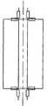
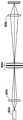
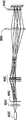
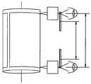
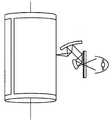
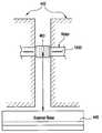
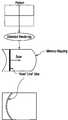
원통형 소재 홀더에 기초한 종래의 이미지 레코더가 그래픽 산업에 사용되고 있다. 도 1A와 1B는 종래의 드럼 스캐너의 예를 제시하고 있다. 본 예에서, 소재는 플라스틱 필름 또는 종이같은 가요성 시트일 수 있다. 도 1B에서, 기판은 칼라 필터 생산용으로 특히 적합한, 열 전달에 의해 디스플레이 장치를 제작하고자 하는 얇은 글래스 시트다.Conventional image recorders based on cylindrical material holders have been used in the graphics industry. Figures 1A and 1B illustrate examples of conventional drum scanners. In this example, the material may be a plastic film or a flexible sheet such as paper. In Fig. 1B, the substrate is a thin glass sheet which is particularly suitable for producing color filters, in which the display device is intended to be manufactured by heat transfer.
디스플레이 스크린 및 태양 전지 패널을 제작하기 위한 관련 기술의 대형 글래스 머신들은 두가지 종류의 문제점들을 내포하고 있다. 즉, 머신 크기와, 기계적 오버헤드라는 문제점을 가지고 있다. 장비의 크기가 클수록, 무겁고 비싸며, 이송이 어렵다. 높은 처리량 요건을 충족시키기 위해, 기계적인 속도가 높아야 한다. 덩치가 큰 것을 고속으로 동작시킬 경우에, 가속 및 감속 시간으로 인해 기계적 오버헤드가 증가한다.Related Art Large glass machines for producing display screens and solar panels have two types of problems. That is, it has a problem of machine size and mechanical overhead. The larger the equipment, the heavier, more expensive, and difficult to transport. In order to meet high throughput requirements, the mechanical speed must be high. When operating a large object at a high speed, the mechanical overhead is increased due to acceleration and deceleration time.
본 발명의 일례의 실시예들은 플랫 패널 디스플레이 및 플랫 패널 디스플레이 제작 방법에 관한 것이다. 예를 들어, 본 발명 중 한개 이상의 실시예들은 얇은 기판을 이용하여 디스플레이를 제조하는 방법을 제공한다. 이러한 디스플레이의 예로는 TFT-LCD, OLED, 그리고 SED가 있다. 그러나, 얇은 기판을 이용하는 그외 다른 디스플레이 기술도 본 발명의 실시예들을 이용할 수 있다. 일례의 실시예들은 시트 물질에 관하여 설명될 것이다. 그러나, 연속 처리나 롤-투-롤(roll-to-roll) 처리에도 이 실시예들을 마찬가지로 적용할 수 있다.Exemplary embodiments of the present invention are directed to flat panel displays and flat panel display manufacturing methods. For example, one or more embodiments of the present invention provide a method of manufacturing a display using a thin substrate. Examples of such displays include TFT-LCDs, OLEDs, and SEDs. However, other display technologies utilizing thin substrates may also utilize embodiments of the present invention. Exemplary embodiments will be described with respect to the sheet material. However, these embodiments can be applied to continuous processing and roll-to-roll processing as well.
본 발명의 일례의 실시예들은 대형 글래스 크기를 이용하는 장치 및 방법들을 제공한다. 한가지 이상의 실시예에서, 글래스는 원통형으로 롤링될 수 있고, 따라서, 길이당 1/3 만큼 물리적 크기를 감소시킬 수 있다. 일례의 실시예들은 원통형의 모양을 가지며, 이는 글래스의 견고하고 컴팩트한 움직임을 가능하게 하여 머신 중량을 감소시킨다. 일례의 실시예들은 비교적 얇은 글래스(가령, 0.7mm, 0.62 mm. 또는 0.5 mm 두께)를 이용한다. 글래스가 얇을수록 가요성이 커져서, 1미터 직경의 실린더에 롤링될 수 있다.Exemplary embodiments of the present invention provide apparatus and methods that utilize a large glass size. In one or more embodiments, the glass can be rolled into a cylindrical shape, thus reducing the physical size by one third per length. Exemplary embodiments have a cylindrical shape, which allows robust, compact movement of the glass, reducing machine weight. Exemplary embodiments utilize relatively thin glass (e.g., 0.7 mm, 0.62 mm. Or 0.5 mm thick). The thinner the glass, the greater the flexibility and can be rolled into a cylinder of 1 meter diameter.
한가지 이상의 실시예는 한개의 모듈러 플랫폼(modular platform)과, 툴 바들을 제공한다. 모듈러 플랫폼은 소재를 홀딩하고 이동시키기 위한 스테이지 상에 배치될 수 있고, 툴 바는 기판 위에서의 처리 및 분석 작용들을 수행하기 위해 툴을 운반하고 이동시키도록 구성될 수 있다. 스테이지, 툴바, 그리고, 툴은 여러가지 조합으로 사용될 수 있고, 표준화된 기계식, 기압식, 유압식, 전기식, 전자식, 서버형, 그리고 정보 통신 인터페이스들 중 한가지 이상을 가질 수 있다.One or more embodiments provide a modular platform and toolbars. The modular platform may be disposed on a stage for holding and moving the workpiece, and the tool bar may be configured to transport and move the tool to perform processing and analysis operations on the substrate. Stages, toolbars, and tools can be used in many combinations and can have more than one of the standardized mechanical, pneumatic, hydraulic, electric, electronic, server, and information communication interfaces.
일례의 실시예들은 대형 기판의 품질 분석 및 그외 다른 평가작용들을 수행하기 위한 기기 플랫폼(instrument flatform)을 제공한다. 한개 이상의 실시예들은 디스플레이 장치, 솔라 패널, LED, 전계발광(electroluminescent) 및 그외 다른 고상 발광 패널들의 제작에 이용하기 위한 처리 플랫폼을 제공한다.Exemplary embodiments provide an instrument platform for performing quality analysis of large substrates and other evaluation operations. One or more embodiments provide a processing platform for use in the fabrication of display devices, solar panels, LEDs, electroluminescent and other solid state luminescent panels.
한개 이상의 실시예들은 5 m2 이상의 소재의 고정밀 측정 및 처리에 이용될 수 있다. 이러한 소재는 글래스, 플라스틱, 또는 금속일 수 있으며, 1mm 두께 이하일 수 있다. 본 발명의 실시예들은 세척, 증착, 어닐링, 에칭, 코팅, 현상, 스트리핑, 러빙, 검사, 수리, 패턴처리, 싱귤레이션, 스크라이빙, 아이솔레이션 등등에 사용될 수 있고, 또한, 분석, 측정, 리뷰, 검사, 수리 등등에도 사용될 수 있다. 여러 경우에, 반도체 소자들이 이러한 공정들을 이용하여 소재 상에 형성될 수 있다. 예를 들어, LCD-TFT 스크린용의 트랜지스터 어레이에서, OLED 용의 트랜지스터 백플레인에서, 도는 그외 다른 디스플레이 타입에서, OLDE 구조 자체, 솔라패널 상의 광전 장치(photovoltaic device)에서, 그리고, LED 및 전계발광 패널 등등의 경우에 이용될 수 있다.One or more embodiments may be used for high precision measurement and processing of materials of 5 m2 or more. Such a material may be glass, plastic, or metal, and may be less than 1 mm thick. Embodiments of the present invention can be used for cleaning, deposition, annealing, etching, coating, development, stripping, rubbing, inspection, repair, patterning, singulation, scribing, isolation, , Inspection, repair, and so on. In many cases, semiconductor devices can be formed on the material using these processes. For example, in transistor arrays for LCD-TFT screens, transistor backplanes for OLEDs, other display types, OLDE structures themselves, photovoltaic devices on solar panels, and LEDs and electroluminescent panels And the like.
도 1A와 도 1B는 종래의 처리 시스템들의 도면.Figures 1A and 1B are diagrams of conventional processing systems.
도 2A는 일례의 실시예에 따른 플랫폼.2A is a platform according to an exemplary embodiment;
도 2B는 일례의 실시예에 따른 스테이지, 툴바, 툴, 그리고 컨트롤에 기초한 모듈러 장비 시스템.Figure 2B illustrates a modular instrument system based on a stage, a tool bar, a tool, and a control according to an exemplary embodiment.
도 3A-3E는 일례의 실시예에 따른 베어링 배열.Figures 3A-3E illustrate a bearing arrangement according to an exemplary embodiment.
도 4는 발명의 일실시예에 따른 플랫폼 도면.4 is a platform diagram according to an embodiment of the invention;
도 5는 발명의 일실시예에 따른 플랫폼 도면.5 is a platform diagram according to an embodiment of the invention;
도 6은 발명의 일실시예에 따른 플랫폼 도면.6 is a platform diagram according to one embodiment of the invention.
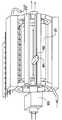
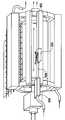
도 7은 발명의 일실시예에 따른 플랫폼을 포함하는 광학 기록 장치의 도면.7 is a view of an optical recording apparatus including a platform according to an embodiment of the invention.
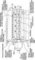
도 8은 발명의 일실시예에 따른 광학 기록 장치의 도면.8 is a view of an optical recording apparatus according to an embodiment of the present invention.
도 9A-9C는 발명의 일실시예에 따른 광학 기록 장치의 광학 기록 헤드에 포함된 광학 채널의 도면.9A-9C are diagrams of optical channels included in an optical recording head of an optical recording apparatus according to an embodiment of the present invention.
도 9D-9E는 발명의 일실시예에 따른 광학 라이팅 장치를 이용하여 제조될 수 있는 2차원 팬-아웃 패턴의 도면.9D-9E are diagrams of a two-dimensional fan-out pattern that may be fabricated using an optical writing apparatus according to an embodiment of the invention.
도 9F, 9G, 9H는 도 9B나 9C에 사용될 수 있는 모듈러 소자들의 도면.Figures 9F, 9G, 9H are diagrams of the modular elements that can be used in Figures 9B and 9C.
도 10A는 발명의 일실시예에 따른 광학 기록 헤드의 도면.10A is a view of an optical recording head according to an embodiment of the present invention.
도 10B는 발명의 일실시예에 따른 패턴 인쇄 방법의 도면.10B is a diagram of a pattern printing method according to an embodiment of the invention.
도 10C는 발명의 일실시예에 따른 광학 기록 헤드의 도면.10C is a view of an optical recording head according to an embodiment of the invention.
도 10D-10G는 발명의 일실시예를 이용하여 생성되는 기록사항의 도면.Figures 10D-10G are diagrams of recorded matters generated using one embodiment of the invention.
도 10H는 일례의 레이저 스캐너의 도면.10H is a diagram of an example laser scanner.
도 11은 발명의 일실시예에 따라 하우징에 둘러싸인 처리 플랫폼의 도면.11 is a view of a processing platform surrounded by a housing in accordance with one embodiment of the invention.
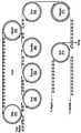
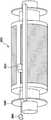
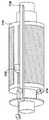
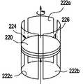
도 12A는 발명의 일실시예에 따른 원통형 스테이지의 도면.12A is a view of a cylindrical stage according to one embodiment of the invention.
도 12B는 소재가 캡처되거나 통과될 수 있도록 처리 트랙 내에서 원통형 스테이지가 배열될 수 있는 방식을 도시하는 도면.12B illustrates a manner in which a cylindrical stage can be arranged within a processing track such that a material can be captured or passed through;
도 12C는 직렬로 배열된 복수의 원통형 스테이지의 도면.Figure 12C is a view of a plurality of cylindrical stages arranged in series.
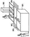
도 13은 일실시예에 따른 처리 유닛의 도면.13 is a diagram of a processing unit according to one embodiment.
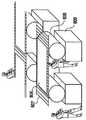
도 14A와 14B는 도 13의 처리 유닛의 일례의 배열들의 도면.Figures 14A and 14B are diagrams of an example arrangement of the processing unit of Figure 13;
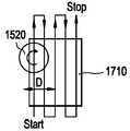
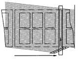
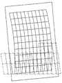
도 15A와 15B는 종래의 단일 플랫베드 머신(도 15A)과 일실시예에 따른 원통형 머신(도 15B)에 필요한 플로어 공간의 비교도.Figures 15A and 15B show a comparison of the floor space required for a conventional single flatbed machine (Figure 15A) and a cylindrical machine (Figure 15B) according to one embodiment.
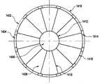
도 16은 실린더의 일실시예의 단면도.16 is a cross-sectional view of one embodiment of a cylinder;
도 17은 일실시예에 따른 조정가능한 밸런스 웨이트를 포함하는 실린더의 도면.17 is a view of a cylinder including an adjustable balance weight in accordance with one embodiment.
도 18A는 일실시예에 따른 원통형 스테이지의 수평 배향도.18A is a horizontal orientation view of a cylindrical stage in accordance with one embodiment.
도 18B는 일실시예에 따른 원통형 스테이지의 수직 배향도.18B is a vertical orientation view of a cylindrical stage in accordance with one embodiment.
도 19는 일실시예에 따른, 소재와 면하는 다공질 에어 쿠션을 가진 비-접촉 푸셔의 도면.19 is a view of a non-contacting pusher having a porous air cushion facing the workpiece, according to one embodiment.
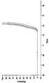
도 20은 단축 방향으로 휘어진 글래스 표면의 응력, 글래스 두께, 그리고, 실린더의 직경 간의 관계를 나타내는 실린더 직경 대 글래스 두께의 그래프.20 is a graph of the cylinder diameter versus glass thickness showing the relationship between the stress on the surface of the glass curved in the minor axis direction, the thickness of the glass, and the diameter of the cylinder.
도 21A와 21B는 일례의 실시예에 다른 프리-스트레싱 장치의 도면.21A and 21B are views of a pre-straining apparatus according to an exemplary embodiment.
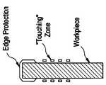
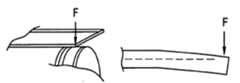
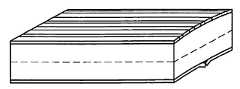
도 22A-22D는 취급 중 손상을 방지하기 위해 소재의 에지를 보호하기 위한 보호 코팅의 도면.Figures 22A-22D illustrate a protective coating for protecting the edges of a material to prevent damage during handling.
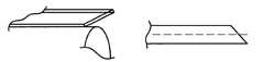
도 23A-23D는 발명의 일실시예에 따른, 글래스의 내측 부분과 같은 높이로 에지가 드레싱되는 것을 방지하는 방법의 도면.Figures 23A-23D illustrate a method of preventing an edge from being dressed to the same height as the inner portion of the glass, according to one embodiment of the invention.
도 24A와 24B는 발명의 일실시예에 따른, 글래스 에지의 절단 방법의 도면.24A and 24B are diagrams of a method of cutting a glass edge, according to an embodiment of the invention.
도 25A-25C는 브리틀한 필름에 크랙이 형성되는 방식을 나타내는 도면. 도 23A에 도시되는 바와 같이, 글래스는 위쪽 및 아래쪽 모두에 필름을 가질 수 있고, 중립층이 중간에 형성될 수 있다.25A-25C are diagrams illustrating a manner in which cracks are formed in a brittle film. As shown in Fig. 23A, the glass may have a film on both the upper and lower sides, and a neutral layer may be formed in the middle.
도 26은 ITO 필름의 응력 변형에 따라 저항이 어떻게 증가하는 지를 나타내는 그래프.26 is a graph showing how the resistance increases with the strain of the ITO film.
도 27은 일실시예에 따라, 실린더에 로딩되기 전에 소재(가령, 글래스)의 온도를 제어하는 장치의 도면.27 is an illustration of an apparatus for controlling the temperature of a workpiece (e.g., glass) prior to loading into a cylinder, according to one embodiment.
도 28A와 28B는 종래의 원통형 좌표계의 도면.28A and 28B are diagrams of a conventional cylindrical coordinate system.
도 29는 일실시예에 따른 원통형 좌표계의 도면.29 is a view of a cylindrical coordinate system according to one embodiment.
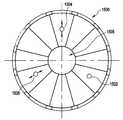
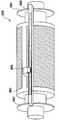
도 30은 일실시예에 따라, 실린더에 좌표계를 구축하기 위한 장치의 도면.30 is an illustration of an apparatus for establishing a coordinate system in a cylinder, according to one embodiment.
도 31A는 회전축 위치의 불확실성, 에지 코드나 노이즈의 비선형성 등등과 같은 에러를 나타내는 도면.31A shows errors such as uncertainty of the position of the rotational axis, nonlinearity of the edge code or noise, and the like.
도 31B는 일실시예에 따라, 인코더 디스크에 대한 각도 측정 개선을 위한 장 치.Figure 31B is an apparatus for improving the angular measurement of an encoder disc, in accordance with one embodiment.
도 32는 일실시예에 따라 축방향 측정을 수행하는 장치의 도면.32 illustrates an apparatus for performing axial measurement in accordance with one embodiment.
도 33은 일실시예에 따라 축방향 측정을 수행하는 장치의 도면.33 illustrates an apparatus for performing axial measurement in accordance with one embodiment.
도 34는 일실시예에 따른 축방향 측정을 수행하기 위한 또다른 장치의 도면.34 is a diagram of another apparatus for performing axial measurement in accordance with one embodiment.
도 35는 일실시예에 따른 공통 좌표계를 생성 및 이용하는 장치의 도면.35 is an illustration of an apparatus for creating and using a common coordinate system in accordance with one embodiment.
도 36A와 36B는 일실시예에 따라, 소재가 롤링되거나 실린더 상에서 구부러질 때, 측정치를 이용하여 플랫한 소재 상에서 좌표계를 연산하는 방법의 도면.36A and 36B are diagrams of a method of computing a coordinate system on a flat workpiece using measurements, when the workpiece is rolled or bent on a cylinder, according to one embodiment.
도 36C는 일실시예에 따라, 글래스의 내면과 외면의 위치를 측정하는 장치의 도면.36C is a view of an apparatus for measuring the position of the inner and outer surfaces of a glass, according to one embodiment.
도 36D와 36E는 추상적 표준 좌표로부터 툴 및 스테이지 좌표로 변환하는 방법 및 이에 대한 역변환의 방법의 도면.Figures 36D and 36E illustrate a method of transforming from abstract standard coordinates to tool and stage coordinates and a method of inverse transformation thereto.
도 37A와 37E는 일실시예에 따른 마스크 얼라이너의 도면.37A and 37E are views of a mask aligner in accordance with one embodiment.
도 38A는 일실시예에 따른 프로젝션 시스템의 상세도.38A is a detailed view of a projection system according to one embodiment.
도 38B-38C는 일실시예에 따라 실린더 상의 필드의 휨을 보상하기 위한 방법의 도면.Figures 38B-38C illustrate a method for compensating deflection of a field on a cylinder in accordance with one embodiment.
도 38D는 일실시예에 따른 프로젝션 얼라이너의 도면.38D is a view of a projection aligner in accordance with one embodiment.
도 38E는 기판 위 영역의 종래 사용의 도면.38E is a diagram of a conventional use of a region above a substrate;
도 38F는 일실시예에 의해 가능해진 용도의 도면.Figure 38F is an illustration of an application enabled by one embodiment.
도 39는 풀-필드 마스터로부터 인쇄를 행하는 롤 프린터의 도면.39 is a view of a roll printer for performing printing from a full-field master;
도 40은 멀티-오퍼레이션 시스템의 일실시예 도면.40 is an embodiment of a multi-operation system;
도 41은 일실시예에 따른 열 전달 패턴처리 장치의 도면.41 is a view of an apparatus for processing a heat transfer pattern according to an embodiment;
도 42A와 42B는 재사용된 도너 필름의 도면.42A and 42B are diagrams of a reused donor film.
도 43은 일실시예에 따른 현상 시스템의 도면.43 is a view of a developing system according to one embodiment.
도 44는 일실시예에 따른 실린더 스테이지를 이용한 진공 또는 폐쇄 환경 처리의 도면.44 is a view of a vacuum or closed environment process using a cylinder stage in accordance with one embodiment;
도 45는 여러가지 검사 및 수리 툴을 포함하는 시스템의 도면.45 is a diagram of a system including various inspection and repair tools.
도 46A와 46B는 일실시예에 따른 블랙 매트릭스 형성 방법의 도면.46A and 46B illustrate a method of forming a black matrix according to one embodiment.
도 47은 일실시예에 따른 블랙 매트릭스 형성 방법의 도면.47 illustrates a method of forming a black matrix in accordance with one embodiment.
도 48은 일실시예에 따른, 처리 플랫폼을 포함하는 툴에 의해 덮힌 실린더 영역의 도면.Figure 48 is a view of a cylinder region covered by a tool including a processing platform, in accordance with one embodiment.
도 49A-49D는 일실시예에 따라, 툴의 순차적 임의-액세스 이동을 수행하기 위한 방법의 도면.49A-49D illustrate a method for performing a sequential random-access movement of a tool, according to one embodiment.
도 50A-50C는 툴과 실린더 제어 시스템들의 위치 에러 도입에 의해 생성되는 의동적 왜곡이, 처리 후 발생될 것으로 예측되거나 소재 상에 이미 존재하는 왜곡과 어떻게 매칭될 수 있는 지를 나타내는 도면.Figures 50A-50C illustrate how the dynamic distortions of the tool and cylinder control systems generated by the introduction of position errors can be predicted to occur after processing or can be matched with distortion already present on the workpiece.
도 51은 일실시예에 따라, 층들 간에 누적된 계통적 왜곡 및 잔류 비계통적 오버레이 에러를 교정하기 위한 방법의 순서도.51 is a flowchart of a method for calibrating accumulated systematic distortion and residual non-systematic overlay errors between layers, in accordance with one embodiment;
도 52는 일실시예에 따라 동시에 인쇄된 화소들의 일례의 공간 배열의 도면.52 is a diagram of a spatial arrangement of an example of simultaneously printed pixels according to one embodiment.
도 53은 동시에 인쇄되는 멀티플 필드의 도면.Figure 53 is a diagram of multiple fields printed simultaneously.
도 54A-54D는 일실시예에 따라, 모이레 효과를 약화시키고 이러한 발생을 억 제하는 방법의 도면.Figures 54A-54D illustrate a method of weakening the moire effect and suppressing such an occurrence, in accordance with one embodiment.
도 55는 소재가 회전하는 경우, 기록 헤드가 회전하는 경우, 그리고 의도적 왜곡이 도입되는 경우의 실시예 도면.FIG. 55 is an embodiment of a case in which a material rotates, a recording head rotates, and intentional distortion is introduced; FIG.
도 56 및 도 57은 일실시예에 따라 소재 패턴을 회전시키는 두가지 방법의 도면.56 and 57 are views of two methods for rotating a workpiece pattern according to one embodiment.
도 58은 일실시예에 따른 플랫폼의 도면.58 is a view of a platform according to one embodiment.
도 59, 60, 61, 61A, 61B는 일실시예에 따른 범용 플랫폼의 도면.59, 60, 61, 61A, 61B are views of a general purpose platform according to an embodiment.
도 62는 소재의 고속 패턴처리를 위한 도 560의 플랫폼의 일례의 공정의 도면.Figure 62 is a drawing of an example process of the platform of Figure 560 for high speed pattern processing of a workpiece.
도 63은 스캐닝 중 스테이지 및 카운터 매스의 위치에 대한 다이어그램.Figure 63 is a diagram of the position of the stage and counter mass during scanning.
도 64A-64E는 일실시예에 따라 x 방향 및 y 방향으로 연속적인 스캐닝을 이용하여 영역을 충진하는 방법의 도면.Figures 64A-64E illustrate a method of filling regions using continuous scanning in the x and y directions, according to one embodiment.
도 65A는 일실시예에 따른 단일-포인트 기록 유닛들의 단일 링을 가진 로터 스캐너 도면.65A is a rotor scanner with a single ring of single-point recording units according to one embodiment.
도 65B는 일실시예에 따른, 각각의 기록 유닛에 대해 필요한 조정과, 소재의 에지들 간의 순차적으로 라인들을 기록하는 단일-링 단일-포인트 스캐너의 단순화된 도면.65B is a simplified illustration of a single-ring single-point scanner that records the sequential lines between the edges of a material and the necessary adjustments for each writing unit, according to one embodiment.
도 65C는 일실시예에 따른, 각각의 기록 유닛에 대해 필요한 조정과, SLM 필드로부터 이미지를 구축하는 공간광 변조기(SLM)을 이용하는 로터 스캐너의 도면.65C is a diagram of a rotor scanner that utilizes a spatial light modulator (SLM) to make necessary adjustments for each recording unit and to build an image from the SLM field, in accordance with one embodiment.
도 66은 일실시예에 따른 기록 장치의 도면.66 is a view of a recording apparatus according to an embodiment;
도 67은 일실시예에 따른 소재들 간 교정 센서들의 배열 도면.67 is an arrangement view of calibration sensors between materials according to an embodiment;
도 68은 일실시예에 따른 교정 센서의 측면도.68 is a side view of a calibration sensor according to one embodiment;
도 69는 일실시예에 따른 교정 센서의 개략적 도면.69 is a schematic diagram of a calibration sensor according to one embodiment.
도 70은 일실시예에 따른 조합형 광학 기록 유닛과 광학 측정 유닛의 도면.70 is a view of a combined optical recording unit and an optical measuring unit according to an embodiment;
도 71A-71C는 일실시예에 따른 디스크형 기록 장치의 여러가지 구현예 및 방위각들의 도면.71A-71C are views of various embodiments and azimuth angles of a disc-shaped recording apparatus according to an embodiment.
도 72A-72C는 일실시예에 따른 링-타입 기록 장치의 여러가지 구현예 및 방위각들의 도면.72A-72C are views of various implementations and azimuth angles of a ring-type recording device in accordance with one embodiment.
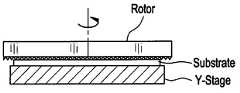
도 73은 일실시예에 따른 수평 배향 원통형 스테이지/홀더의 도면.73 is a view of a horizontally oriented cylindrical stage / holder in accordance with one embodiment.
도 74는 일실시예에 따른 기록 장치를 이용하여 기록될 수 있는 플랫한 소재의 도면.74 is a view of a flat material that can be recorded using a recording apparatus according to an embodiment;
도 75는 일실시예에 따른 오토 포커스 배열의 도면.75 is a view of an autofocus arrangement in accordance with one embodiment.
도 76은 일실시예에 따른 교정 센서의 평면도.76 is a plan view of a calibration sensor according to an embodiment;
도 77은 일실시예에 따른 기록 장치의 사시도.77 is a perspective view of a recording apparatus according to an embodiment;
도 78은 일실시예에 따른 기록 장치의 도면.78 is a view of a recording apparatus according to an embodiment;
도 79는 도 15에 도시된 기록 장치(1520)의 평면도.79 is a plan view of the
도 80은 일실시예에 따른 기록 장치의 도면.80 is a view of a recording apparatus according to an embodiment;
도 81A는 일실시예에 따른 기록 장치의 측면도.81A is a side view of a recording apparatus according to an embodiment;
도 81B는 도 81A에도시된 기록 장치의 평면도.81B is a plan view of the recording apparatus shown in Fig. 81A. Fig.
도 82는 일실시예에 따라 카테시안 그리드를 휨 좌표계로 변환하는 방법의 도면.82 illustrates a method of transforming a Cartesian grid into a warp coordinate system in accordance with one embodiment;
도 83은 실린더 상에 소재를 홀딩하는 진공 배열의 도면.83 is a view of a vacuum arrangement for holding a material on a cylinder;
도 84는 일실시예에 따른 기록 장치의 도면.84 is a view of a recording apparatus according to an embodiment;
도 85는 도 78에 도시된 패턴 발생기의 상세도.FIG. 85 is a detailed view of the pattern generator shown in FIG. 78; FIG.
도 86A-86E는 일실시예에 따라, x 방향 및 y 방향으로 연속 스캐닝하는 방법의 도면.Figures 86A-86E illustrate a method of continuous scanning in the x and y directions, according to one embodiment.
도 87-90은 일실시예에 따른 플랫베드 플랫폼의 도면.87-90 are views of a flatbed platform in accordance with one embodiment.
도 91은 스캐닝 중 스테이지 및 카운터 매스의 위치에 대한 다이어그램.91 is a diagram of the position of the stage and counter mass during scanning;
도 92는 일실시예에 따른 교정 시스템의 도면.92 is a diagram of a calibration system in accordance with one embodiment.
도 93은 일실시예에 따른 교정 방법의 도면.93 is a diagram of a calibration method in accordance with one embodiment.
도 94A-94K는 일실시예에 따라, 소재에 대한 로터 스캐너의 방향과 관련한 소재 헤드의 여러가지 위치를 나타내는 도면.94A-94K are views showing various positions of a workpiece head in relation to the orientation of a rotor scanner relative to a workpiece, according to one embodiment.
도 95A-95E는 로터 스캐너의 회전 방향에 대한 SLM 배열과 소재 배열의 도면.95A-95E are views of an SLM arrangement and a workpiece arrangement for the direction of rotation of a rotor scanner.
본 발명의 실시예들을 대형 기판을 처리하기 위한 플랫폼을 제공한다. 발명의 일실시예에 다른 플랫폼은 질량이 작고, 기계적 오버헤드가 작으며, 다양한 처리 툴에 용이하게 일체화될 수 있다.Embodiments of the present invention provide a platform for processing large substrates. Other platforms in one embodiment of the invention are small in mass, small in mechanical overhead, and easily integrated into various processing tools.
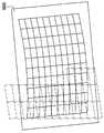
도 2A는 일실시예에 따른 플랫폼을 도시한다. 도 2A의 플랫폼은 프레임(202)을 포함할 수 있다. 프레임(202)은 상부 및 하부 지지 구조(213U, 213L)와 단부 지 지 구조(214L, 214R)를 포함할 수 있다. 지지 구조(213U, 213L, 214L, 214R)는 금속성 물질의 연속적 피스(가령, 시트 금속)로 만들어질 수 있고, 온도 제어를 위해 튜브(207)를 내장할 수 있다. 지지 구조(213U, 213L, 214L, 214R)의 온도는 방향(217)을 따라 튜브(207)를 통과하는 유체 흐름(가령, 공기, 액체, 기체, 등등)에 의해 제어될 수 있다. 대안으로, 지지구조(213U, 213L, 214L, 214R)가 조각조각 형태로 형성될 수 있고, 이 경우에 각각의 지지 구조가 개별적으로 형성되어 차후에 조립될 수 있다.2A illustrates a platform according to one embodiment. The platform of Figure 2A may include a
각각의 단부 지지 구조(214L, 214R)는 다수의 장착 표면(211)들을 포함하는 데, 이 장착 표면에는 다수의 툴바(210)들이 배열될 수 있고, 장착되거나 고정될 수 있다. 실린더나 원통형 스테이지(201)가 프레임(202) 내에 배열될 수 있다. 실린더(201)는 약 1미터의 직경, 2미터의 길이를 가질 수 있다. 실린더(201)는 베어링(216)을 이용하여 회전축(212) 상에 장착될 수 있다. 모터(203)같은 구동 장치가실린더축(212)의 한 단부에 부착될 수 있다. 구동 장치(203)는 회전축(212)을 구동시켜서, 실린더(201)로 하여금 방향(218)으로 회전하게 할 수 있다. 실린더(201)는 약 500kg일 수 있으며, 베어링(216)은 가령, 유체 베어링(hydrostatic fluid bearings)일 수 있다. 그러나, 임의의 적절한 베어링이 사용될 수도 있다. 유체는 가령, 에어, 액체, 기체 등등일 수 있다. 유체 베어링은 당 분야에 잘 알려져있으며, 따라서, 구체적 설명은 생략한다.Each
한가지 예에서, 직경 1미터, 길이 2.5미터의 실린더가 유체 베어링에 의해 지지될 수 있다. 이 축은 로터의 확장부일 수도 있고, 고정될 수도 있다.In one example, a cylinder with a diameter of 1 meter and a length of 2.5 meters can be supported by a fluid bearing. This axis can be an extension of the rotor or it can be fixed.
도 3A-3D는 일실시예에 따라 유체 베어링을 배열하는 여러가지 방식을 제시하고 있다. 도 3A-3C는 수평 실린더용 베어링 배열을, 도 3D는 수직 실린더용 베어링 배열을 제시하고 있다. 베어링 표면은 도 3A-3D에서 굵은 선으로 표시된다.Figures 3A-3D present various schemes for arranging fluid bearings in accordance with one embodiment. Figures 3A-3C show the bearing arrangement for the horizontal cylinder and Figure 3D show the bearing arrangement for the vertical cylinder. The bearing surface is shown in bold lines in Figures 3A-3D.
도 3E는 실린더 상의 휨 모멘트(bending force)를 제거할 수 있는 베어링의 배열로서, 회전 중 원심력 효과로 인한 휨을 억제할 수 있다. 수평 방향으로, 이 배열은 한 단부에 유체 베어링이 배열되며, 이 배열이 탄성력에 의해 유체 베어링에 대해 푸쉬될 수 있다. 탄성력은 베어링이 압력과 진공 모두를 이용할 경우 베어링 자체에 의해 생성될 수 있다. 이러한 방식으로, 실린더나 축의 온도 팽창에 따라, 베어링이 형성되지 않을 수도 있다.FIG. 3E is an arrangement of bearings capable of eliminating the bending force on the cylinder, and can suppress the warping due to the centrifugal force effect during rotation. In the horizontal direction, this arrangement has fluid bearings arranged at one end, and this arrangement can be pushed against the fluid bearing by elastic force. The elastic force can be generated by the bearing itself if the bearing uses both pressure and vacuum. In this way, depending on the temperature expansion of the cylinder or the shaft, the bearing may not be formed.
도 2A에서, 프레임(202)과 실린더(201)의 온도는 강제 냉각에 의해 제어될 수 있다. 강제 냉각(forced cooling)은 방향(206)으로 회전 축(2120을 통해 유체를 흐르게 함으로서 수행될 수 있다. 프레임(202)과 실린더(201)의 온도는 섭씨 0도와 0.01도 사이의 온도로 제어될 수 있다. 예를 들어, 실린더의 온도는 섭씨 0.05도 또는 0.01도로 제어될 수 있다.In Fig. 2A, the temperature of the
도 2A에서, 처리 플랫폼은 실린더(201)에 소재를 이송시키기 위한 컨베이어(208)를 또한 포함할 수 있다. 소재를 실린더(201)로 로딩하거나 실린더(201)로부터 언로딩하는 것은 도 18A 및 도 18B를 참고하여 상세하게 설명될 것이다.In Fig. 2A, the processing platform may also include a
일실시예에 따른 처리 플랫폼은 모듈러 시스템으로 구성될 수 있고, 이 경우에, 원통형 스테이지에 한 개 또는 여러개의 툴바들이 구성될 수 있다. 각각의 툴바는 한개 이상의 툴을 가질 수 있다. 그 결과, 단일 툴만을 이용하여 종래의 처리 속도로 단일 기능이 구현될 수 있다. 일례의 실시예들은 단일 툴바에 복수의 툴들을 이용하여, 또는, 복수의 툴 바에 복수의 툴을 이용하여, 더 높은 용량을 취급할 수도 있다. 동일한 시스템에 복수의 기능들이 구성될 수 있다. 일실시예에 따르면, 처리 툴들은 처리 결과 분석 및 소재 정렬을 위한 처리 기능 및 방법들같이 복수의 기능들을 가질 수 있다.The processing platform according to one embodiment may be configured as a modular system, in which case one or more toolbars may be configured on the cylindrical stage. Each toolbar can have one or more tools. As a result, a single function can be implemented at a conventional processing rate using only a single tool. Exemplary embodiments may handle a higher capacity using a plurality of tools on a single toolbar, or using a plurality of tools on a plurality of toolbars. A plurality of functions can be configured in the same system. According to one embodiment, the processing tools may have multiple functions, such as processing functions and methods for processing result analysis and material alignment.
표준화된 인터페이스를 가진 모듈러 플랫폼 설계는 활용성(flexibility)을 증가시킬 수 있다. 표준화된 인터페이스는 기계적 인터페이스, 전기적 인터페이스, 통신 인터페이스, 좌표계, 진단 루틴, 사용자 인터페이스 표현, 등등을 포함할 수 있다. 실린더 스테이지에 여러가지 툴들이 장착될 수 있으나, 동일한 툴이 모듈러 시스템에 구성된 플랫-베드 스테이지에 또한 사용될 수 있어서, 모듈러 시스템에서의 활용성(flexibility)을 증가시킨다. 모듈러 시스템은 서로 다른 디스플레이 제작자들이 서로 다른 스크린 크기에 대해 고정될 필요가 없고, 따라서, 동일 세대일 지라도 서로 다른 기판 크기에 대해 고정될 필요가 없다. 재사용가능한 인터페이스 및 컴포넌트들을 가진 모듈 방식의 접근법은 주문형 방식과 관련된 비용을 절감시킬 수 있다.Modular platform design with standardized interfaces can increase flexibility. A standardized interface may include a mechanical interface, an electrical interface, a communication interface, a coordinate system, a diagnostic routine, a user interface representation, and so on. Various tools may be mounted on the cylinder stage, but the same tool may also be used in a flat-bed stage configured in a modular system, thereby increasing the flexibility in the modular system. The modular system does not require different display manufacturers to be fixed for different screen sizes and therefore need not be fixed for different substrate sizes, even in the same generation. A modular approach with reusable interfaces and components can reduce costs associated with custom methods.
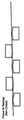
도 2B는 일실시예에 따른 모듈러 시스템을 도시한다. 도시되는 바와 같이, 모듈러 시스템은 스테이지, 툴바, 그리고 툴을 포함할 수 있다. 인터페이스들의 일부분이 모듈들 간의 선으로 표시된다.Figure 2B illustrates a modular system in accordance with one embodiment. As shown, the modular system may include a stage, a tool bar, and a tool. Portions of the interfaces are indicated by lines between the modules.
일부 인터페이스들이 표준화되어 모듈들이 교환될 수 있다. 이는 툴바 및 툴용 또는 소프트웨어용 표준화 운동학적 마운트같은 기계적 레스트를 포함한다. 표 준화된 소프트웨어 인터페이스는 동일한 공정들이 모듈들에 의해 그리고 모듈 상에서 수행될 수 있게 한다.Some interfaces are standardized so that modules can be exchanged. This includes mechanical rests, such as standardized kinematic mounts for toolbars and tools or software. A standardized software interface allows the same processes to be performed by modules and on modules.
추가적으로, 모듈들 중 일부는 공통 좌표계를 가질 수 있다. 예를 들어, 동일한 결함에 대해 검사 카메라와 수리 툴이 동일한 좌표를 이용할 수 있다. 한가지 예에서, 공통 좌표계는 소재 상의 좌표들을 참조할 수 있고, 특히, 표준화된 상태, 휨, 응력, 온도 상태, 공정 완료후 섭씨 22도에서 전면이 플랫한 조건에서 응력없는 상태에서의 소재 상의 좌표를 참조할 수 있다. 공통 좌표계는 동일한 방식으로 배향될 수 있고, 동일한 위치에서 원점을 가지며, 하지만 일부 예에서는 좌표계가 여러가지 툴과 툴바 사이에서 정확하게 (나노미터 레벨까지) 정렬될 필요가 있다.Additionally, some of the modules may have a common coordinate system. For example, the same coordinates can be used by the inspection camera and the repair tool for the same defect. In one example, the common coordinate system can refer to the coordinates on the workpiece, and in particular the coordinates of the workpiece in the stressed state at normal conditions, bending, stress, temperature conditions, flat front at 22 degrees Celsius after completion of the process Can be referred to. The common coordinate system can be oriented in the same way, with the origin at the same position, but in some instances the coordinate system needs to be precisely aligned (to the nanometer level) between various tools and toolbars.
공통 좌표계를 이용할 때, 하드웨어 및 교정의 상당 부분이 추상화될 수 있다. 예를 들어, 표준화된 상태, 스테이지 상의 소재의 왜곡, 온도, 또는 정렬 상태, 툴의 정렬 상태 등등에서 소재를 위한 공통 좌표계에는 MOVE TO 공정만이 주어질 수 있고, 좌표 변환은 낮은 추상층(the lower abstraction layers)(가령, 머신, 소재 제어, 또는 교정 시스템)에 의해 교정될 수 있다.When using a common coordinate system, much of the hardware and calibration can be abstracted. For example, in a common coordinate system for a material in a normalized state, distortion of a material on a stage, temperature or alignment state, tool alignment, etc., only a MOVE TO process may be given, abstraction layers (e. g., a machine, material control, or calibration system).
도 2B를 참조할 때, 스테이지 모듈들은 원통형 스테이지(8301), 플랫-베드 스테이지(8302), 그리고, "스테이지-레스" 스테이지("stage-less" stage)를 포함할 수 있으며, 이때, 처리 또는 측정이 트랜스포트 컨베이어(8303) 상에서 이루어진다. 스테이지들은 스테이지 컨트롤러(8306)에 대한, 그리고, 한 개 이상 종류의 툴바들에 대한 표준 인터페이스를 가지며, 툴 무브먼트(8305)가 있을 수도, 툴 무브먼트(8304)가 없을 수도 있다. 복수의 툴 타입(8307, 8308, 8309, 8310)이 한개 이 상의 툴바에 장착될 수 있고, 툴바들은 툴 제어 하드웨어 및 소프트웨어, 교정 소프트웨어, 진단 장치 등등을 지닌 데이터 시스템과 인터페이싱될 수 있다. 모듈러 시스템은 동일한 시스템에 대해 복수의 동작을 동시에 수행할 수 있다.Referring to Figure 2B, the stage modules may include a
도 2A를 참조할 때, 마우팅 표면(211)에 한개 이상의 툴바(210)가 배열되거나 장착될 수 있다. 그러나, 발명의 일실시예에 따르면, 플랫폼들이 임의의 수 및 임의의 종류의 툴들을 포함하는 임의의 수의 툴바를 포함할 수 있다.Referring to FIG. 2A, one or
도 4는 일실시예에 따른 플랫폼을 도시한다. 도시되는 바와 같이, 도 4의 플랫폼은 도 2A의 플랫폼과 실질적으로 유사하다. 단지, 도 4의 플랫폼은 추가적인 툴바(302)를 포함하며, 이 툴바(302)에는 툴(301)이 장착되어 있다. 구동 장치(203)는 임의의 각도로 스테이지(201)를 회전시킬 수 있고, 툴(301)은 툴바(302)를 따라 미끄러질 수 있다. 그래서, 툴(301)은 실린더(201) 상에 로딩되는 소재의 표면 위 임의의 지점에 액세스할 수 있다.4 illustrates a platform according to one embodiment. As shown, the platform of Figure 4 is substantially similar to the platform of Figure 2A. 4 includes an
도 4에서, 툴바(302)는 소재 상에 좀더 정확한 좌표계를 구성하기 위해 한개 이상의 측정 장치(301)를 포함할 수 있다. 좌표계는 글래스의 휨에 대한 교정치를 고려하여 연산될 수 있다. 예를 들어, 소재(가령, 글래스 시트)가 차후에 플랫한 상태로 놓였을 때 실제 좌표를 제공하기 위한 것이다. 플랫한 좌표계의 연산은 아래에서 상세하게 설명될 것이다.In Figure 4, the
한개 이상의 실시예에서, 측정 장치(301)는 소재 상에 앞서 형성되거나 패턴처리된 층의 특징부들과 글래스의 표면 상의 기준들을 판독하기 위한 광학 소자들을 포함할 수 있다. 측정 장치(301)의 광학 소자들은 고정될 수도 있고, 툴바(302) 를 따라 미끄러질 수도 있어서 소재 상의 임의의 지점에 액세스할 수도 있다. 측정 장치(301)로부터의 데이터는 다양한 동작이나 기능 구현에 사용될 수 있다. 예를 들어, 측정 장치(301)로부터의 데이터가 고속 처리/코팅/에칭에 의해 생성되는 왜곡 평가에 사용되는 측정에 사용될 수 있다. 측정 장치는 형성된 패턴에 대한 분석, 검사, 패턴처리, 또는 처리 툴들의 정렬에 또한 사용될 수 있어서, 현 동작(가령, 패턴처리)과 이전 패턴 간의 좀더 정교한 오버레이를 위해 온-더-플라이로 왜곡 맵을 생성할 수 있다. 그리고, 좌표계나 지지 구조의 흔들림이나 왜곡을 모니터링하는 데 사용될 수 있다.In one or more embodiments, the measuring
일례의 처리 플랫폼은 측정 장치를 가진 툴바만을 포함하도록 구성되어, 기판 측정 시스템으로 불릴 수 있다. 기판 측정 시스템은 수십 나노미터 수준의 정확도를 가질 수 있다.An exemplary processing platform may be configured to include only a tool bar with a measurement device, which may be referred to as a substrate measurement system. The substrate measurement system can have an accuracy of several tens of nanometers.
툴은 툴바를 따라 미끄러지다가 분석을 위해 한개 이상의 위치에서 정지할 수 있다. 예를 들어, 현미경같은 툴은, 툴이 정지하고 비디오이미지를 운영자에게 전송할 때, 소재 상에 자동적으로 포커싱될 수 있다. 정밀 위치설정이 운영자에 의해 또는 이미지 인지에 의해 이루어질 수 있기 때문에, 툴이 특정 위치를 결정할 때의 정확도는 적정한 수준이기만 하면 된다. 다용도 분석 플랫폼을 생성하기 위해 동일 플랫폼에 다른 분석적 기기들이 일체화될 수도 있다. 다른 분석적 기기의 예로는 엘립소미터, 리플렉토미터, 스캐터로미터, FTIR 및 다양한 종류의 카메라같은 광학 기기들과, STM, AFM, 니어 필드 광학 프로브, 스캐닝 자기 프로브, 켈빈 프로브, 프로필로미터같은 스캐닝 프로브 기기, 포톤, 전자, 이온, 원자, 또는 X-선을 이용하는 표면 분석 툴, 접촉각 프로브, 온도 프로브, 음향 마이크로스코프, 등등과 같은 화학적/물리적 프로브, 그리고, 4점 프로브 및 그외 다른 기기들과 같은 전기적 테스트 기기들이 있다.The tool can slide along the toolbar and stop at one or more locations for analysis. For example, a tool such as a microscope may be automatically focused on a material when the tool is stopped and the video image is transmitted to the operator. Since the precise positioning can be done by the operator or by the image, the accuracy only when the tool determines a particular position is reasonable. Other analytical instruments may be integrated into the same platform to create a versatile analytical platform. Examples of other analytical instruments include optical instruments such as ellipsometers, reflectometers, scatterometers, FTIR and various types of cameras, as well as STM, AFM, nearfield optical probes, scanning magnetic probes, Kelvin probes, Chemical / physical probes such as surface analysis tools, contact angle probes, temperature probes, acoustic microscopes, etc., using the same scanning probe instrument, photon, electron, ion, atom or X-ray, There are electrical test instruments such as
도 4의 플랫폼은 툴바용의 추가적으로 자유로운 복수의(가령, 4개의) 위치들을 가지며, 복수의(가령, 5개의) 기기들을 홀딩할 수 있다. 각각의 기기는 스테이지의 전체 폭을 스캐닝한다. 일실시예에 따른 플랫폼들은 임의의 수의 툴바들을 포함할 수 있으며, 복수의 툴들이 각각의 툴 바에 장착될 수 있다.The platform of Figure 4 has an additional free (e.g., four) locations for the toolbar and can hold multiple (e.g., five) devices. Each device scans the entire width of the stage. Platforms according to one embodiment may include any number of toolbars, and a plurality of tools may be mounted on each toolbars.
소재는 TFT 스크린이나 그외 다른 종류의 디스플레이 장치를 제작하는 데 사용되는 반도체(가령, 실리콘) 기판일 수 있다. 사용가능한 글래스 크기는 실린더 크기에 따라 좌우될 수 있다. 표 1은 여러가지 실린더들에 대해 이용가능한 글래스 크기들을 도시한다. 도시되는 바와 같이, L은 길이를, D는 실린더 스테이지의 직경을 나타낸다.The material may be a semiconductor (e.g., silicon) substrate used to fabricate a TFT screen or other type of display device. The usable glass size may depend on the cylinder size. Table 1 shows the available glass sizes for various cylinders. As shown, L represents the length and D represents the diameter of the cylinder stage.
표 1Table 1

길이 3000mm, 직경 1000mm의 플랫폼에 대해 G9(2400x2800mm)이 표 1에서 가장 큰 표준 크기 글래스로 도시되지만, 플랫폼은 더 큰 글래스 시트를 취급할 수 있다. 가령, 실린더가 클 경우 4m x 6m 까지도 가능하다.For platforms with a length of 3000 mm and a diameter of 1000 mm, the platform is capable of handling larger glass sheets, although G9 (2400 x 2800 mm) is shown in Table 1 as the largest standard size glass. For example, if the cylinder is large, it can be up to 4m x 6m.
TFT 디스플레이들은 칼라 필터에 대해 한개의 글래스 시트와 트랜지스터 어레이에 대해 한개의 글래스 시트, 즉, 총 두개의 글래스 시트를 포함할 수 있다. 두 글래스 시트 모두 유사한 처리과정을 통해 제작될 수 있다. 가령, 박막의 블랭킷 증착, 포토리소그래피에 의한 패턴처리, 그리고 에칭에 의해 제작될 수 있다. 각각의 글래스 시트는 0.5 mm 내지 0.7mm의 두께를 가질 수 있고, 2m x 3m 까지의 크기가 가능하다. 그러나 글래스의 두께나 크기가 이와 다를 수도 있다.TFT displays may include one glass sheet for the color filter and one glass sheet for the transistor array, i.e., a total of two glass sheets. Both glass sheets can be made through a similar process. For example, blanket deposition of thin films, patterning by photolithography, and etching. Each glass sheet may have a thickness of from 0.5 mm to 0.7 mm and may be up to 2 m x 3 m in size. However, the thickness and size of the glass may be different.
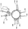
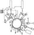
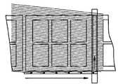
도 5는 일실시예에 따른 플랫폼을 제시한다. 도 5의 플랫폼은 도 2A의 플랫폼과 유사하지만, 도 5의 플랫폼은 측정 툴바(402)와 검사 툴바(404)를 포함하는 점에 차이가 있다. 검사 툴바(404)는 복수의(가령, 4개의) 광학 검사 헤드(406)를 포함할 수 있다. 광학 검사 헤드(406)는 서로 같은 것일 수도 있고, 서로 다른 것일 수도 있다.Figure 5 illustrates a platform according to one embodiment. The platform of FIG. 5 is similar to the platform of FIG. 2A, but differs in that the platform of FIG. 5 includes a
도 5와 관련하여, 화살표로 표시되는 바와 같이, 실린더(201)는 회전할 수 있고, 광학 헤드(404)는 툴바(404)를 따라 슬라이딩하여 실린더 상에 로딩된 소재의 전체 폭을 덮을 수 있다. 각각의 광학 헤드(406)는 카메라로 소재의 스트라이프를 판독할 수 있고, 판독된 스트라이프를 공지된 기준 패턴에 비교할 수 있다. 기준 패턴은 동일한 스트라이프의 시간 지연된 부분일 수 있고, 데이터베이스로부터 얻은 기준 패턴이거나, 동일한 또는 또다른 툴바 상의 또다른 툴로부터의 패턴일 수도 있다. 판독된 스트라이프를 동일한 스트라이프의 시간지연된 부분과 비교하거나, 또다른 툴로부터의 패턴과 비교하는 것은, 다이-투-다이 검사(die-to-die inspection)로 불리며, 판독된 스트라이프를 데이터베이스로부터 얻은 기준 패턴과 비교하는 것은, 다이-투-데이터베이스 검사(die-to-database inspection)로 불린다. 일례의 실시예들은 개별적으로 또는 조합하여 각각의 방법을 이용할 수 있다.5, the
예를 들어, 다이-투-다이 검사는 주기적인 패턴의 부분들에 대해 사용될 수 있고, 다이-투-데이터베이스 검사는 주기적이지 않은 패턴 부분들에 대해 사용될 수 있다. 복수의 툴이 구성되면, 여러 상황에 다이-투-데이터베이스 검사를 이용할 수 있다. 광학 검사 헤드(406)는 시간 지연 및 일체화(TDI) 카메라같은 카메라일 수 있다. TDI 카메라는 움직이는 물체에 대해 날카로운 이미지를 제공할 수 있다.For example, a die-to-die inspection can be used for portions of the periodic pattern, and a die-to-database inspection can be used for non-periodic pattern portions. Once multiple tools are configured, a die-to-database scan can be used for a variety of situations. The
도 6은 일실시예에 따른 플랫폼을 도시한다. 도 6의 플랫폼은 도 2A에 도시된 플랫폼과 유사하다. 다만, 도 6의 플랫폼은 복수의(가령, 두개의) 패턴처리 툴바(502, 504)를 포함하는 점에 차이가 있다. 각각의 패턴처리 툴바(502, 504)는 한개 이상의 잉크제트 기록 헤드(506)를 포함할 수 있다. 예를 들어, 툴바(502, 504)는 두개의 잉크제트 기록 헤드를 포함한다. 각각의 잉크 제트 헤드(506)는 실린더(201)가 회전할 때 스타라이트 모양의 영역을 기록하거나 충진할 수 있다. 잉크제트 기록 헤드가 툴바(502, 504)를 따라 축방향으로 슬라이딩될 때 이 스트라이프는 실린더(201)의 회전을 통해 동시 스캐닝으로 인해 비스듬한 각도를 가질 수 있다. 잉크제트 헤드(506)는 오버래핑 스타라이프를 기록할 수 있고, 패턴처리, 기록, 또는 인쇄 공정은 두개 이상의 패스에 연계될 수 있다. 다시 말해서, 잉크제트 기록 헤드(506)는 소재의 동일 부분을 두번 이상 지나게 된다.6 illustrates a platform according to one embodiment. The platform of Figure 6 is similar to the platform shown in Figure 2A. 6 differs in that the platform of FIG. 6 includes a plurality of (e.g., two)
소재는 칼라 필터 생산용 기판일 수 있고, 잉크제트 기록 헤드(506)는 칼라 필터 도트와 블랙 매트릭스 패턴들을 인쇄할 수 있다. 잉크제트 기록 헤드는 스페 이서, LCD 액체 자체, 레지스트, 폴리이미드, 유기/무기 유전체, 패시베이션, 또는 보호 필름, 유기 LED용 액티브층, 금속 및 무기층용 프리커서 등등을 인쇄할 수도 있다.The material may be a substrate for producing a color filter, and the ink
도 7은 일실시예에 따른 플랫폼을 포함하는 광학 라이터(optical writer)를 제시한다. 도시되는 바와 같이, 도 7의 광학 라이터는 도 2A의 플랫폼을 포함할 수 있고, 한개 이상의 추가 툴바(602)를 포함할 수 있다. 툴바(602)는 한개 이상의 툴(604)을 포함하는 단일 패턴처리 툴바일 수 있다. 본 예에서, 툴바(602)는 단일 툴(604)을 포함할 수 있고, 이 툴(604)은 레이저 스캐너를 포함하는 광학 기록 헤드일 수 있다. 레이저 스캐너는 다각형 레이저 스캐너일 수 있고, 또는 그외 다른 적절한 레이저 스캐너일 수 있다. 그러나 도 7과 관련하여 다각형 레이저 스캐너를 참고하여 설명이 이어질 것이다. 툴바(602)에 고정된 레이저(608)는 레이저 스캐너에 레이저 빔(606)을 제공한다. 레이저(608)는 펄스형 엑시머 레이저, 연속 레이저, 변조 연속 레이저 등등 중 한가지일 수 있다. 그러나, 도 7은 약 100ns의 주기를 가진 펄스형 레이저를 참고하여 설명될 것이다. 한가지 예에서, 레이저(608)의 파장은 약 1.06 미크론이며, 펄스 반복 속도는 약 50kHz다. 펄스 에너지는 약 10mJ이고, 총 에너지는 약 500W다. 레이저 펄스는 전자 회로(도시되지 않음)에 의해 트리거링될 수 있다. 전자 회로는 다음 펄스의 시간 위치를 연산할 수 있어서, 실린더 스캐닝, 툴 스캐닝, 그리고 서브-스캐닝(가령, 툴 위치에 대한 스캐닝) 등등과 같은 스캐닝 움직임에 기초하여 소재 상의 구체적 위치를 조명할 수 있다.Figure 7 illustrates an optical writer including a platform according to one embodiment. As shown, the optical writer of Fig. 7 may include the platform of Fig. 2A and may include one or more
도 7의 광학 라이터는 기판에 반도체 소자를 직접 형성하는 것처럼, 레지스 트를 이용하지 않으면서 패턴을 형성하기에 적합하다. 이를 직접 구조형성법(direct structuring)이라 부른다. 직접 구조형성의 예로는 레이저 애블레이션, 열 전달 리소그래피, 등등이 있다. 직접 구조형성 프로세스에 따라, 파장이 다를 수 있다. 예를 들어, 레이저 빔(606)의 파장이 1.06nm 내지 0.193 nm 일 수 있다. 추가적으로, 또는 앞서에 대한 대안으로, 펄스 에너지가 높거나 낮을 수 있고, 펄스 반복 주파수가 높거나 낮을 수 있으며, 한개 이상의 스캐너 툴을 가진 복수의 툴바들이 직접 구조형성 프로세스에 따라 사용될 수 있다.The optical writer of Fig. 7 is suitable for forming a pattern without using a resistor, such as directly forming a semiconductor element on a substrate. This is called direct structuring. Examples of direct structure formation include laser ablation, heat transfer lithography, and the like. Depending on the direct structure formation process, the wavelengths may be different. For example, the wavelength of the
툴(604)의 레이저 스캐너는 특정 응용분야에 따라 다양한 방식으로 구현될 수 있다. 예를 들어, 레이저 스캐너가 갈바노미터, 다각형, 홀로그래픽 소자 또는 마이크로미캐니컬 소자, 음향-광학 또는 전계-광학 소자 또는 실린더나 툴의 기계적 스캐닝일 수 있다. 추가적으로 또는 이에 대한 대안으로, 광선을 스캐닝하는 일례의 방법들은 음향-광학, 전계-광학, 회전 또는 발진 기계식 또는 마이크로기계식, 그리고 홀로그래픽 스캐닝, 실린더나 툴에 의한 스캐닝 등등이 있을 수 있다.The laser scanner of the
일실시예에 따른 광학 라이터는 포톤 에너지나 열을 이용하여 잠재적인 또는 직접적인 패턴을 생성하는 데 사용될 수 있다. 잠재적인 또는 직접적인 패턴들은 포토레지스트, 에멀젼, 금속이나 합금 필름, 유기 필름, 또는 그외 다른 감광 물질에 기록될 수 있다. 또다른 실시예에서, 물질이 애블레이션에 의해 제거될 수 있고, 패턴 형성은 레이저-유도 화학 반응, 레이저-유도 표면 에너지/화학물질 변화, 도너 필름이나 소재로부터의 레이저-유도 물질 전이에 따라 좌우될 수 있다. 일실시예에 따르면, 광학 라이터가 소재의 패턴처리를 위해 원자 빔이나 대전 입자 빔 을 이용할 수 있다.An optical writer according to one embodiment can be used to generate a potential or direct pattern using photon energy or heat. Potential or direct patterns can be recorded in a photoresist, emulsion, metal or alloy film, organic film, or other photosensitive material. In yet another embodiment, the material can be removed by ablation and the patterning is dependent on laser-induced chemical reactions, laser-induced surface energy / chemical changes, laser-induced material transfer from the donor film or material . According to one embodiment, the optical writer may use an atomic beam or a charged particle beam for patterning the workpiece.
광학 기록 헤드를 이용할 때, 패턴들은 한개 이상의 스캐닝 레이저 빔에 의해 형성될 수 있어서, 렌즈 어레이로부터 한개 이상의 개별적으로 변조된 어레이의 스팟들을 이용하여, 또는 1차원 또는 2차원적인 공간 광 변조기를 이용하여 투사될 수 있다. 레이저 빔의 파장은 EUV, 과진공 UV, deep UV, mid UV, near UV, 가시광, 근적외선에서 원적외선까지, 또는 이들 간의 조합 내에서 선택될 수 있다. 한개의 파장을 가진 복사광 생성을 위해 갈륨 나이트라이드의 밴드갭을 이용한 레이저에 의한 조명은 미국특허 7,098,993 호에 상세하게 개시되어 있다. 대안으로, 레이저 빔의 파장이 1nm 내지 100 미크론 사이에서 선택될 수 있다. 레이저(608)는 연속, 또는 준연속, 또는 직접 변조형 또는 펄스형일 수 있다. 레이저 기록 장비의 여러 실시예들은 GDSII, Gerber, OASIS 포맷 등등과 같은 벡터형 또는 알고리즘형 포매으로 입력 패턴 사양을, 데이터 경로에 의한 광학 기록 하드웨어를 위한 변조 신호로 변환시킬 수 있다.When using an optical recording head, the patterns can be formed by one or more scanning laser beams, so that the spots of one or more individually modulated arrays from the lens array, or by using a one- or two-dimensional spatial light modulator Can be projected. The wavelength of the laser beam may be selected within EUV, vacuum UV, deep UV, mid UV, near UV, visible, far infrared to far infrared, or combinations thereof. Laser illumination using a bandgap of gallium nitride for generating one wavelength of radiation is disclosed in detail in U.S. Patent No. 7,098,993. Alternatively, the wavelength of the laser beam may be selected between 1 nm and 100 microns. The
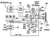
도 8은 일실시예에 따른 광학 라이터(optical writer)의 도면이다. 도 8의 광학 라이터는 도 7의 광학 라이터와 유사하다. 다만, 도 8의 광학 라이터는 복수의 연속 다이오드 레이저 채널들을 포함하는 광학 라이팅 헤드(702)를 구비하고 있는 점에 차이가 있다. 본 실시예에서, 레이저 다이오드들은 406nm의 파장을 가진 레이저 빔을 발생시킬 수 있다. 각각의 레이저 다이오드는 소재 상의 주어진 스팟을 향해 레이저 빔을 방사할 수 있다. 광학 기록 헤드(702)는 복수의 레이저 다이오드(가령, 12,000개)를 포함할 수 있다. 실린더가 회전할 때 기록되는 평행한 선 들의 수가 레이저 다이오드들의 수와 같도록 레이저 다이오드들이 배열될 수 있다. 8 is a diagram of an optical writer according to an embodiment. The optical writer in Fig. 8 is similar to the optical writer in Fig. However, the optical writer of FIG. 8 differs in that it has an
10nm/s의 회전 속도에서, 6m2의 소재 면적은 분당 1미크론2의 화소들로 기록되거나 커버될 수 있다. 레이저 다이오드들은 약 10MHz의 온/오프 속도로 직접 변조될 수 있다.At a rotational speed of 10 nm / s, the material area of 6 m2 can be recorded or covered with 1 micron2 pixels per minute. The laser diodes can be directly modulated with an on / off speed of about 10 MHz.
도 8에서, 광학 기록 헤드(702)는 프로젝션 광학 소자들을 추가로 포함할 수 있다. 도 9A는 광학 기록 헤드(702)에 포함된 일례의 프로젝션 광학 소자들을 도시한ㄷ.In Fig. 8, the
도 9A와 9B는 도8의 광학 기록 헤드 툴에 적층된 광학 채널들의 실시예들을 제시한다.Figures 9A and 9B illustrate embodiments of optical channels stacked on the optical recording head tool of Figure 8;
도 9A에서, 광학 채널(800A)은 레이저 다이오드(802A)로부터 출력되는 레이저 빔의 품질을 정형 및 클리닝하기 위한 공간 필터(806A)를 포함할 수 있다. 도 9A는 광원(802A)(가령, 레이저 다이오드)이 (레이저 다이오드로의 전류 변조에 의해) 변조될 수 있는 간단한 배열을 제시한다. 이 빔은 렌즈(808A)에 의해 소재 상에 포커싱될 수 있다. 현실세계의 레이저 다이오드들의 빔 품질은 고품질 리소그래피용으로 충분하지 않을 수 있고, 도 9A는 공간 필터(804A, 804B)에 의해 필터링되는 빔을 도시한다. 일실시예에 따르면, 광원이 변조되지 않고 외부 변조기가 사용될 수 있다.In FIG. 9A, the optical channel 800A may include a
도 9B는 일실시예에 따른 또다른 광학 채널을 제시한다. 도 9B의 광학 채널은 개별적으로 변조되는 복수의 빔들을 포함할 수 있다.9B illustrates another optical channel in accordance with one embodiment. The optical channel of Figure 9B may comprise a plurality of individually modulated beams.
도 9B에서, 레이저 광원(802B)으로부터의 레이저 빔은 빔 스플리터나 팬-아웃 소자(가령, 팬-아웃 회절 광학 소자 DOE)에 의해 분리될 수 있고, 복수의 빔들이 개별적으로 변조되어(가령, 투과 장치로 나타나는 것처럼 전계광학 또는 마이크로미캐니컬 변조기들을 이용. 하지만, 일례의 실시예들이 반사 변조기, 음향광학 변조기, 또는 그외 다른 적절한 타입의 변조기에도 적용될 수 있음) 소재 상에 투영될 수 있다. 본 예에서, 단일 레이저 광원(802B)이 복수의 변조 빔들(가령, 32개)을 제공할 수 있고, 빔 당 단가가 절감될 수 있다. 한개 이상의 실시예에서, 12,000개의 레이저 빔들이 12,000/32, 즉, 375개의 광학 채널들에 의해 생성될 수 있다. 즉, 각각의 채널은 32개의 빔들을 생성한다.9B, the laser beam from the
도 9C는 렌즈 어레이(810C)를 추가한 점을 제외하고는 도 9B의 실시예와 유사하다. 렌즈 어레이는 나머지 광학 소자들이 비교적 작은 개구수(NA)로 구성될 수 있게 하고, 따라서, 단순화될 수 있다. 시스템의 분해능은 렌즈 어레이의 개구수에 의해 결정되며, 이는 상당히 높을 수 있다(가령, NA=0.25). 렌즈 어레이 소자들이 또한 작을 수 있고, 더 짧은 촛점 길이를 가질 수 있으며, 축 상에서만 사용될 수 있다. 작은 렌즈들은 큰 렌즈에 비해 구체적 웨이브프론트 품질로 만들기가 용이하며, 렌즈(808B)가 6-10개의 광학 소자들을 필요로할 때, 각각의 렌즈 어레이 소자들이 한개의 (구형) 굴절 표면일 수 있다. 도 9C의 왜곡은 어레이의 제작 허용공차에 의해 제어될 수 있고, 도 9B에서처럼 렌즈(808B)의 렌즈 소자들의 정렬에 의해서는 제어될 수 없다.Figure 9C is similar to the embodiment of Figure 9B, except that a
상술한 바와 같이, 도 9C의 광학 채널은 도 9B의 광학 채널과 유사하다. 그 러나, 도 9C의 광학 채널은 렌즈 어레이(808C)를 추가로 포함하고 있는 점에 차이가 있다. 렌즈 어레이(808C)는 렌즈에 요구되는 에텐듀(etendue)(가령, 개구수와 필드의 곱)를 완화시킬 수 있다. 왜냐하면, 각각의 렌즈가 축 상에 단일 포인트만을 이미징하기 때문이다. 렌즈 어레이는 각각의 빔에 대해 단일 (비구면) 표면을 가질 수 있다.As described above, the optical channel in Fig. 9C is similar to the optical channel in Fig. 9B. However, there is a difference in that the optical channel of Fig. 9C further includes a
축 상에 사용되는 작은 렌즈들의 경우, 단일 표면의 광학적 품질이 적당할 수 있다. 렌즈 어레이(808C)는 회절 렌즈 소자들을 이용함으로서, 또는 굴절 표면을 장착하거나 에칭함으로서 생성될 수 있다. 각각의 레이저 빔을 복수의 빔으로 나누는 렌즈 어레이를 이용하는 경우, 도 9A에 도시된 바와 같이 채널 당 한개의 레이저를 갖추는 경우에 비해 비용을 절감할 수 있다.For small lenses used on an axis, the optical quality of a single surface may be adequate. The
도 9D는 표면-충진 패턴에 부착될 수 있는 138개의 빔들의 (806C) 위치에서의 모습을 2차원 팬-아웃 패턴으로 도시한다. 이러한 팬-아웃 패턴을 생성할 수 있는 렌즈 어레이는 도 9E에 도시되는 렌즈 어레이(808C)와 유사하다. 단지, 본 예에서는 프로젝션 시스템의 이미지 역전을 위해 렌즈 어레이가 180도 회전할 수 있다는 점에 차이가 있을 뿐이다. 일례의 실시예들은 렌즈들을 적층하기 위해 6각형 패턴을 가지며, 회전 및 잘려질 수 있어서, 툴이 실질적으로 동등하게 이격된 138개의 평행선들을 소재 상에 그릴 수 있다. 툴이 실린더와 동시에 연속적으로 이동할 경우, 빔 패턴은 조합된 스캐닝 각도로 회전될 수 있다. 빔 패턴의 롬빅 인벨롭(rhombic envelope)은 다음 스트라이프에 대한 부드러운 전이를 제공할 수 있다. 왜냐하면, 좌측 스트라이프로부터 점점 더 적은 수의 빔들이 제공되며, 반면에 우 측 스트라이프로부터는 점점 더 많은 수의 빔들이 제공되기 때문이다. 대안으로, 스트라이프 경계 부근에서 라인들이 두번 기록될 수 있다. 즉, 좌측에 한번, 우측에 한번 기록될 수 있다. 반면에, 전체 노광 도즈가 비-오버랩 영역에서처럼 오버래핑 지역에서도 동일하게 유지되어, 사용되는 파워가 절감될 수 있다.FIG. 9D shows a view at a location of 138
도 9F, 9G, 9H는 도 9B 또는 9C에 사용될 수 있는 모듈러 소자들을 도시한다. 도 9F는 (806B) 또는 (806C)에 대응하는 모듈러 소자들의 성긴 어레이를 도시한다. 모듈러 소자들의 성긴 어레이는 격자 광 밸브에 기초한 모듈러 패치들의 어레이일 수 있다. 이러한 패치가 도 9G에 상세하게 제시된다. 반사 미러 스트립들이 반사 상태로 설정될 수도 있고(이 경우에 모든 반사 표면적들이 동일 상태에 있음), 비-반사 상태로 설정될 수도 있다(이 경우에 일부 스트립들은 소멸 간섭을 일으킬 수 있는 위치로 정전적으로 당겨져서, 비-반사 상태가 생성되는 것임). 도 9H에서, 서로 다른 마이크로미캐니컬 반사 변조기 패치가 도시된다. 본 예에서, 틸팅 미러가 레이저 빔을 또다른 방향으로 점반사 방식으로 보냄으로서(가령, DMD-타입 미러) 또는 회절에 의해서(가령, 회절 마이크로미러), 반사를 소멸시킬 수 있다. 이는 당 분야에 잘 알려져 있다. 일례의 실시예에서는 전계광학 변조기들의 어레이나 액정 셔터를 이용한다.Figures 9F, 9G, 9H illustrate modular elements that can be used in Figures 9B or 9C. 9F shows a coarse array of modular elements corresponding to 806B or 806C. The coarse array of modular elements may be an array of modular patches based on a grating light valve. This patch is shown in detail in FIG. 9G. The reflective mirror strips may be set to a reflective state (in which case all reflective surface areas are in the same state) and may be set to a non-reflective state (in which case some of the strips may be set to a position Is totally pulled, resulting in a non-reflective state). In Figure 9H, different micromanicular reflective modulator patches are shown. In this example, reflection can be extinguished by sending a laser beam in a point reflection manner (e.g., a DMD-type mirror) or diffraction (e.g., a diffractive micromirror) in a tilting mirror. This is well known in the art. In an exemplary embodiment, an array of field optical modulators or a liquid crystal shutter is used.
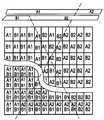
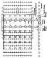
도 52는 일실시예에 따른, 동시에 인쇄되는 화소들의 공간 배열을 도시한다. 도 52의 화살표는 스캐닝 방향을 나타낸다.52 illustrates a spatial arrangement of simultaneously printed pixels, according to one embodiment. Arrows in Fig. 52 indicate the scanning direction.
도 52에서, (5000A-5000C)는 화소들의 치밀한 매트릭스다. 가령, 직사각형의 각 변들과 함께 정렬되는 어레이의 행과 열들을 가진 장방형 공간 광 변조기의 이 미지들이다. (5000A)는 기록 방향에 평행한 화소 그리드를 가진 공간 광 변조기(SLM)를 도시한다. 다시 말해서, (5000A)에서는 스캐닝 방향으로 정렬되고, (5000B)에서는 45도 회전되며, (5000C)는 이와는 다른 각도로 회전한다. (5000D, 5000E, 5000F)는 45도만큼 SLM 변에 대해 회전한 어레이를 가진 치밀한 매트릭스의 이미지들로서, 각각 0도, 45도, 그리고 제 3의 각도만큼 회전한 경우를 도시한다. (5000G)는 스캐닝 중 여러 다른 위치에서 행들이 나타나도록 회전된 성긴 매트릭스다. (5000H)는 화소들의 성긴 라인으로서, 영역 충진이 바람직할 경우, 영역을 채우기 위해 복수의 패스들을 요구할 수 있다. (5000I)는 1차원 공간 광 변조기의 이미지를 나타내는 치밀한 단일 라인을 도시한다. (5000J)와 (5000K)는 스캐닝 방향으로 변위된 화소들을 가진 단일 라인이다.In Fig. 52, (5000A-5000C) is a dense matrix of pixels. For example, images of a rectangular spatial light modulator with rows and columns of arrays aligned with each side of the rectangle. (5000A) shows a spatial light modulator (SLM) having a pixel grid parallel to the recording direction. In other words, (5000A) is aligned in the scanning direction, (5000B) is rotated 45 degrees, and (5000C) is rotated at an angle different from this. (5000D, 5000E, 5000F) are dense matrix images with arrays rotated about 45 degrees with respect to the sides of the SLM, respectively, and rotated by 0 degree, 45 degree, and a third angle, respectively. (5000G) is a sparse matrix rotated so that rows appear at several different locations during scanning. (5000H) is a sparse line of pixels, which may require a plurality of passes to fill the area if area filling is desired. RTI ID = 0.0 > 5000I < / RTI > shows a dense single line representing an image of a one-dimensional spatial light modulator. (5000J) and (5000K) are single lines with pixels displaced in the scanning direction.
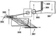
도 10A와 10C는 일실시예에 따른 광학 기록 헤드를 도시한다. 도 10A 및 도 10C의 광학 기록 헤드는 일실시예에 따른 광학 라이터의 툴바에 포함될 수 있다.10A and 10C illustrate an optical recording head according to an embodiment. The optical recording head of Figs. 10A and 10C can be included in the toolbar of the optical writer according to an embodiment.
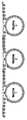
도 10A는 격자 광 밸브(GLV)같은 1차원 공간 광 변조기(3902)에 기초한 기록 헤드를 도시한다. 한 라인의 변조기 소자(3903)들이 복수의 광원(3907)에 의해 조명될 수 있다. 이때, 광원(3907)의 예로는 LED, 레이저 다이오드, 광섬유 연결 레이저 다이오드, 가스 레이저, 엑시머 레이저, 고상 레이저(파장 변환 유/무 가능), 등등이 있다. 이러한 조명 광학 소자들은 왜상(anamorphic) 광학 소자(3908)들을 가질 수 있다. 이는 변조기 소자들에 대해 한개의 광원으로부터 광을 퍼지게 할 수 있고, 이때, 모든 광은 변조기 소자들의 라인 사이의 방향으로 한 라인으로 컬렉팅된다. 1차원 공간광 변조기의 각각의 소자는 한개 이상의 광원에 의해 조명될 수 있고, 공간광 변조기에 대해 간섭 패턴을 생성하지 않기 위해 각도, 편광, 또는 파장에 의해 서로 분리될 수 있다. 소재(3901) 상의 포커싱 렌즈 시스템을 이용하여 이미지(3904)가 형성될 수 있고, 광학 헤드와 소재 간의 상대적 움직임이 스트라이프(3905)를 생성할 수 있다.10A shows a recording head based on a one-dimensional spatial
공간광 변조기 라인의 이미지는 소재의 축에 대해 평행할 수도 있고, 평행하지 않을 수도 있다.The image of the spatial light modulator line may or may not be parallel to the axis of the workpiece.
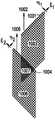
도 10B는 공간 광 변조기(3912, 3913, 등등)의 일련의 이미지들에 의해 패턴(3911, 3917, 3918, 3915, 3916, 3914)을 기록하는 방식을 도시한다. 공간광 변조기 이미지 간의 각도는 "mura"라고 불리는 모이레 효과의 도입을 감소시킨다. 이는 아래에서 상세하게 설명될 것이다. 도 10C는 일실시예에 따른 2차원 공간광 변조기에 기초한 기록 헤드를 도시한다. 한개 이상의 광원이 기록 헤드의 조명 경로의 필드 스탑(field stop)을 조명한다. 렌즈(3908)는 조명 애퍼처(3907) 상에 광을 포커싱시킬 수 있다. 이 조명 애퍼처(3907)는 공간광 변조기(3902)의 액티브 영역(3903)을 조명하는 광의 각도 콘텐트를 결정할 수 있다. 공간 광 변조기는 2차원적인 복수의 마이크로미캐니컬 미러들을 가질 수 있다. 가령, 회절 미러나 틸팅 미러를 가질 수 있다. 또는, 전계광학형 또는 액정 공간광 변조기를 가질 수 있다. 도 10A에 도시되는 바와 같이, 소재(3901) 상에 이미지(3904)가 형성될 수 있고, 복수개의 이미지들이 함께 붙게 되어 스트라이프(3905)를 형성할 수 있다.Fig. 10B shows a manner of
도 10C의 기록 헤드는 x-y 대칭 이미지를 제공하는 두개의 일차원 공간광 변조기의 배열을 도시한다. 두개의 1차원 공간광 변조기(1001, 1004)는 이동 방 향(1002, 1005)에 대해 +/- 45도만큼 기울어질 수 있다. 순차적 방식으로 사용되는 한개의 공간광 변조기, 또는 개별적인 두개의 공간광 변조기가 구성될 수 있다. 공간광 변조기는 스트라이프(1003, 1006)를 기록할 수 있다. 두개의 스트라이프들이 오버랩(1007)되는 경우에, 이미지는 x-y 대칭이다. 이는 도 10E에 도시되고 있다. 도시되는 바와 같이, x와 y는 소재의 좌표들이다. 이동 방향은 y에 대해 평행하다. 공간광 변조기(η)에 수직인 방향으로 이미징은 인코히어런트하며, 공간광 변조기(ξ)에 평행한 방향으로 이미지는 부분적으로 코히어런트하다. 오버랩 영역(1007)에서, 이미지는 제 1 노광 및 제 2 노광의 합일 수 있다. 이때, 도 10E에 제시되는 바와 같이, 제 1 노광과 제 2 노광 간에 ξ과 η이 교환될 수 있다.The recording head of Fig. 10C shows an arrangement of two one-dimensional spatial light modulators providing an x-y symmetric image. The two one-dimensional spatial
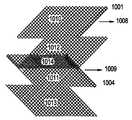
도 10F에서, 이동 방향이 y로부터 x로 변경되면, 시스템은 +/-45도의 회전을 이용하여 실질적으로 동일한 성질로 기록을 행할 수 있다. 두개의 공간광 변조기를 배치함에 따라, 오버랩이, 현재 기록된 것(1010, 1011)과 그 이전에 기록된 것(1012, 1013) 간에, 또는, 두개의 공간광 변조기(1007)로 단일 패스에서 발생할 수 있다. 두개의 공간광 변조기를 서로 90도로 배열하여, 이 변조기들을 도 10E와 10F에서 도시되는 바와 같이 공간광 변조기의 각도로부터 45도만큼 이동시킴으로서, 성긴 패턴들을 기록함에 있어 높은 유연성을 제공할 수 있다. 스테이지는 수평 방향으로 또는 수직 방향으로 스캐닝을 할 수 있으며, 효율적으로 기록하도록 이 두 방향 모두가 해당 면적을 커버한다.In Fig. 10F, if the direction of movement is changed from y to x, the system can perform recording with substantially the same property using a rotation of +/- 45 degrees. By arranging the two spatial light modulators, an overlap can be made between the currently recorded one 1010 and 1011 and the one previously recorded 1012 and 1013, or two
도 10G는 일례의 패턴을 도시한다. 기판(1020)은 8개의 디스플레이(1021)를 가진다. 각각의 디스플레이는 중앙의 규칙적인 어레이 영역과, 덜 규칙적인 주변 영역을 가질 수 있다. 이 두개의 영역들은 서로 다른 방법을 이용하여 노광될 수 있다. 가령, 규칙적 영역은 작은 마스크의 반복을 이용하여 노광될 수 있고, 주변 영역은 마스크없는 노광을 이용하여 노광될 수 있다. 주변 영역은 홀로 스캐닝될 수 있다. 가령, 먼저 수직 주변 영역이 스캔되고 그후 수평 영역이 스캔될 수 있다. 순서도 물론 바뀔 수 있다. 도 10E에 도시되는 바와 같이, 이 방법은 모이레 효과(mura 효과)를 감소시키기 위해 소재의 좌표 방향들이 서로 이격될 때 사용되고 일반화될 수 있다. 실시예들이 1차원 공간광 변조기에 대해 언급되고 있으나, 한 라인을 따라 한개 이상의 레이저 빔으로 스캐닝을 행하는 다른 기록 기법에도 마찬가지로 적용될 수 있다. 레이저 스캐너들은 상술한 바와 같이 동일한 x-y 비대칭을 가질 수 있고, 따라서, 스트라이프 방향에 관해 유연성을 증가시킬 수 있다.FIG. 10G shows an example pattern.
도 10H는 일례의 레이저 스캐너를 도시한다. 도시되는 바와 같이, 한개 이상의 광원(4702)(가령, 레이저 다이오드, 가스 레이저, 고상 레이저, LED, 연속형, 펄스형, 직접형, 또는 팬-아웃 요소를 통과하는 형태, 등등)이 소재(4704) 상에 스팟(4703)으로 이미징될 수 있다. 스팟은 광학 스캐너(4702)에 의해 소재 위에서 스캐닝된다. 다각형 스캐너가 도시되고 있지만, 전계광학형, 마이크로미캐니컬형, 공진형, 갈바노미터, 프리즘, 홀로그래픽형, 등등의 다른 스캐너들도 사용될 수 있다. 광학 소자들과 소재 간의 상대적 움직임이 스트라이프(4705)를 생성한다.Figure 10H shows an example laser scanner. As shown, one or more light sources 4702 (e.g., laser diode, gas laser, solid state laser, LED, continuous, pulsed, direct, or fan- Gt; 4703 < / RTI > The spot is scanned on the workpiece by the
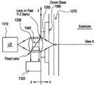
광학 기록 헤드는 정렬 및 포커싱을 위한 카메라 및 센서들을 추가로 포함할 수 있다. 포커싱은 높이 맵을 이용하여 피드-포워드 포커스 시스템에 의해 수행될 수 있고, 이는 스캐닝 전 또는 후에 생성될 수 있다. 높이 맵(height map)은 피드- 포워드 포커스 교정에 사용될 수 있다.The optical recording head may further include a camera and sensors for alignment and focusing. Focusing can be performed by a feed-forward focus system using a height map, which can be generated before or after scanning. The height map can be used for feed-forward focus calibration.
순수한 피드백 포커스 시스템에 비해, 피드-포워드 포커스 시스템은 노이즈를 억제하고 동적 성질을 개선시킬 수 있다. 피드백 시스템은 순간적인 센서 정보를 이용하여 포커스를 교정할 수 있다. 그 결과, 서보 래그(servo lag)라고 알려진 바와 같이, 측정보다 나중에 교정이 이루어진다. 서보 래그를 감소시키기 위해, 전체 서보 루프의 속도가 증가될 수 있다. 그러나, 루프가 빠를수록 노이즈가 증가한다. 피드-포워드 시스템에서는 측정치들이 수거되고 필터링되어 차후 스캔시 사용을 위해 저장될 수 있다. 본 예에서는 래그없이 교정이 이루어질 수 있고, 따라서, 필요한 포커스의 슬루-레이트를 수용하기 위해 서보의 대역폭만이 충분하면 되며, 이 대역폭은 서보 래그에 독립적이다. 포커스 시스템의 동역학은 개선된 동적 성질을 제공할 수 있다.Compared to a pure feedback focus system, the feed-forward focus system can suppress noise and improve dynamic properties. The feedback system can calibrate the focus using instantaneous sensor information. As a result, calibration is performed later than the measurement, known as servo lag. To reduce the servo lag, the speed of the entire servo loop can be increased. However, the faster the loop, the higher the noise. In a feed-forward system, measurements may be collected and filtered and stored for later use in a scan. In this example, calibration can be done without lag, and therefore only the bandwidth of the servo needs to be sufficient to accommodate the slew-rate of the required focus, and this bandwidth is independent of servo lag. The dynamics of the focus system can provide improved dynamic properties.
정렬 및 포커싱을 위한 카메라들은 소재 상에 존재하는 패턴이나 기준점(fiducials)들의 이미지들을 픽업할 수 있고, 컨트롤러가 소재의 왜곡을 실시간으로 연산할 수 있다. 카메라들은 실린더가 정적일 때 이미지를 찍을 수 있고, 펄스형 조명으로 움직임을 정지(freezing)시킬 수 있으며, 고속 스캐닝을 하면서 고품질 캡처를 위해 TDI 센서를 이용할 수 있다.The cameras for alignment and focusing can pick up images of patterns or fiducials present on the material, and the controller can calculate the distortion of the material in real time. Cameras can capture images when the cylinder is stationary, freeze motion with pulsed illumination, and use TDI sensors for high-quality capture while scanning at high speed.
도 10B는 도 10A 또는 10C의 광학 기록 헤드를 이용하여 기록된 패턴을 도시한다.FIG. 10B shows a pattern recorded using the optical recording head of FIG. 10A or 10C.
도 10B에서, 1차원 공간광 변조기(또는 이와 대등한 레이저 스캐너)의 이미지는 데이터의 축에 대해 회전될 수 있다. 데이터는 데이터의 좌표계에 라스터링될 수 있고(3914), 기록 하드웨어의 그리드에 리-매핑될 수 있다(3919). 한개 이상의 실시예에서, 라스터링은 회전하는 하드웨어의 그리드에서 수행될 수 있다. 예를 들어, 하드웨어에 의해 기록되는 각각의 데이터 요소가 기하학적 값(가령, 기본 화소)에 할당될 수 있다. 기본 화소는 오버랩없이 영역을 충진할 수 있다. 라스터링 하드웨어는 각 화소의 오버랩 영역을 패턴의 기록된 특징부들로 연산할 수 있다(또는 기록되지 않은 특징부들로 연산할 수 있다).In Fig. 10B, the image of the one-dimensional spatial light modulator (or its equivalent laser scanner) can be rotated about the axis of the data. The data may be rasterized (3914) to the coordinate system of the data and re-mapped (3919) to the grid of the recording hardware. In one or more embodiments, rastering may be performed on a rotating hardware grid. For example, each data element recorded by the hardware may be assigned to a geometric value (e.g., a base pixel). The basic pixel can fill the region without overlap. The rastering hardware may (or may) calculate the overlap region of each pixel with the recorded features of the pattern (or may be computed with the unrecorded features).
일례의 실시예에서, 웨이트 함수가 각 화소의 영역에 대해 할당될 수 있다. 따라서, 화소 맵이 웨이팅된 오버랩이 된다. 추가적으로, 웨이팅된 오버랩 연산에 사용되는 화소들은 부분적으로 오버래핑될 수 있다. 가령, 화소들에 대한 웨이트 함수들이 기본 영역 바깥에 서포트를 가질 수 있다. 다중 노광 패스들이 기록될 경우, 이 패스들은 라스터링되어 서로 다른 그리드 오프셋으로 기록되어, 화소 맵이 두개 이상의 패스 사이에서 서로 다른 결과를 도출한다.In an exemplary embodiment, a weight function may be assigned for each pixel region. Therefore, the pixel map becomes the weighted overlap. Additionally, the pixels used in the weighted overlap operation may be partially overlapping. For example, weight functions for pixels may have support outside the base area. When multiple exposure passes are written, the passes are rasterized and written with different grid offsets, resulting in pixel maps having different results between two or more passes.
도 11은 일실시예에 따른, 하우징에 둘러싸인 처리 플랫폼을 도시한다. 하우징(102)에 포함된 처리 플랫폼은 일실시예에 따른 임의의 처리 플랫폼일 수 있다. 하우징(102)은 진동 차단, 온도 제어, 오염 제어, 그리고 스테이지 조작용 제어 장치들을 위한 그외 다른 컴포넌트들을 하우징할 수도 있다. 도 11의 하우징은 소재를 로딩 및 언로딩시키기 위한 수단들을 또한 구비할 수 있다.Figure 11 illustrates a processing platform surrounded by a housing, according to one embodiment. The processing platform included in the
일실시예에 따른 원통형 스테이지는 다양한 방식으로 배향될 수 있고, 두개 이상의 방향으로 소재를 로딩 및 언로딩시킬 수 있다. 원통형 스테이지가 두개 이상의 방향으로 로딩 및 언로딩되기 때문에, 처리 트랙에서 물질 흐름을 제어 및 변 화시키기 위한 로보트 핸들러(robotic handler)가 생략될 수 있다.The cylindrical stage according to one embodiment can be oriented in various manners and can load and unload materials in two or more directions. Since the cylindrical stage is loaded and unloaded in two or more directions, a robotic handler for controlling and changing the material flow in the processing track can be omitted.
도 12A는 일실시예에 따른, 복수의 입력 및 출력을 가진 실린더 배열을 도시한다.12A shows a cylinder arrangement with a plurality of inputs and outputs, according to one embodiment.
도 12B는 소재가 캡처되거나 패스될 수 있도록 처리 트랙 내에서 원통형 스테이지가 어떻게 배열되는 지를 도시한다. 도시되는 바와 같이, 처리 트랙(1102) 상에 실린 한개 이상의 소재(1100)는 소재의 요망 순서에 따라, 원통형 스테이지(1104)를 통과하거나, 원통형 스테이지(1104)에 의해 캡처된다. 예를 들어, 소재(1100)가 지연될 필요가 있을 경우, 소재(1100)는 원통형 스테이지(1104)에 의해 처리 트랙(1102)으로부터 벗어날 수 있다. 원통형 스테이지(1104) 상에 있을 때, 다른 소재들이 원통형 스테이지(1104)를 통과하여 소재(1100)보다 먼저 처리될 수 있다. 다른 한편, 어떤 지연도 필요치 않을 경우, 소재(1100)는 원통형 스테이지(1104)를 통과하고 처리 트랙(1102) 상에서 계속 진행하게 된다. 이 배열은 품질 제어를 샘플링하는 데 사용되는 것처럼 분석 기기용으로 사용될 수 있다.Figure 12B shows how the cylindrical stage is arranged within the processing track so that the workpiece can be captured or passed. As shown, one or more workpieces 1100 placed on a
원통형 스테이지는 소재를 캡처하고, 홀딩하고, 트랙 상의 소재 순서를 변화시키기 위해 일정 시간 이후에 소재를 다시 내보내는 데 사용될 수 있다. 당 분야에 잘 알려진 바와 같이, 순서대로 놓여있는 두 요소의 순서를 바꾸는 것은 임의적 소팅을 가능하게 하는 상당히 기본적인 동작이며, 소재를 캡처 또는 홀딩하는 기능은 소재의 소팅을 가능하게 한다.The cylindrical stage can be used to capture and hold the material, and to re-export the material after a certain time to change the order of the material on the track. As is well known in the art, changing the order of two elements that are placed in order is a fairly basic operation that allows for arbitrary sorting, and the ability to capture or hold a material enables sorting of the material.
도 12C는 직렬로 배열되는 복수의 원통형 스테이지를 도시한다. 도 12C가 세개의 원통형 스테이지를 도시하고 있으나, 유사한 배열에서는 임의의 숫자의 원통 형 스테이지들을 포함할 수 있다. 도 12C의 각각의 원통형 스테이지는 도 12B에 도시된 원통형 스테이지와 실질적으로 동일하며, 소재를 통과 및 캡처하는 기능을 가진다. 도 12C에 도시되는 배열을 이용할 때, 직렬 연결된 원통형 스테이지들의 수에 총 처리량이 상관될 수 있다. 예를 들어, 원통형 스테이지들이 많을수록, 총 처리량이 커진다. 임의의 소재가 임의의 머신에 전달되어, 처리되고, 다시 처리 트랙 상의 물질 흐름으로 되돌아올 수 있다. 이는 장비의 세 조각들의 조합된 용량을 이용함에 있어 유연성을 개선시킨다. 원통형 스테이지는 세가지 종류의 장비일 수도 있으며, 또는, 소재들 간에 순서를 소팅하거나 변화시키기 위해 사용될 수 있다.Figure 12C shows a plurality of cylindrical stages arranged in series. Although Figure 12C illustrates three cylindrical stages, similar arrangements may include any number of cylindrical stages. Each cylindrical stage of Fig. 12C is substantially the same as the cylindrical stage shown in Fig. 12B, and has the function of passing and capturing material. When using the arrangement shown in FIG. 12C, the total throughput can be correlated to the number of cascaded stages in series. For example, the greater the number of cylindrical stages, the greater the total throughput. Any material may be delivered to any machine, processed, and then returned to the material flow on the processing track again. This improves flexibility in taking advantage of the combined capacity of the three pieces of equipment. The cylindrical stage may be of three types of equipment or may be used to sort or change orders between materials.
소재들이 처리될 수 있고, 소재들의 흐름이 원통형 스테이지를 이용하여 변화될 수 있기 때문에, 도 13에 도시된 바와 같이 좀 더 컴팩트한 처리 유닛들이 실현될 수 있다.Since the materials can be processed and the flow of materials can be changed using a cylindrical stage, more compact processing units as shown in Fig. 13 can be realized.
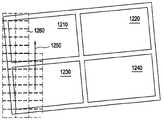
도 13은 일실시예에 따른 처리 유닛을 도시한다. 도 13의 처리 유닛은 리소그래피나 에칭용으로 사용될 수 있다. 도 13에서, 소재는 좌측으로부터 들어온다(가령, stocker로부터 제공된다). 소재는 포토레지스트로 코팅될 수 있고 코팅 스테이션(800)에서 베이킹될 수 있다. 코팅 및 베이킹 이후에, 소재는 노광 스테이션(802)에서 노광될 수 있고 디벨로퍼(804)에서 현상될 수 있다. 현상 후, 소재 상의 결과적인 레지스트 패턴은 검사 스테이션(808)에 의해 검사될 수 있다. 레지스트 패턴이 검사를 통과하지 못할 경우, 소재는 스트립 스테이션(810)에서 벗겨져서, 코팅 스테이션(800)으로 되돌아간다.13 shows a processing unit according to one embodiment. The processing unit of Fig. 13 can be used for lithography or etching. In Fig. 13, the material enters from the left (e.g., provided by stocker). The material may be coated with a photoresist and baked at the
도 13에서, 레지스트 패턴이 검사를 통과할 경우, 소재가 에칭 스테이 션(806)에서 에칭될 수 있고, 검사 스테이션(812)에서 다시 검사될 수 있다. 소재가 검사를 통과하거나 수리가능한 결함을 가질 경우, 소재는 stocker나 수리 스테이션에 출력될 수 있다. 소재가 검사에 실패할 경우, 가령, 소재가 수리불가능한 경우, 소재는 스크랩으로 출력되고 폐기된다.13, when the resist pattern passes the inspection, the material may be etched in the
검사 스테이션(808)에서 소재를 검사함으로서, 그리고 필요시 소재를 재회전시킴으로서, 레지스트 이미지의 결함들이 양품률 결정에서 빠질 수 있다. 유사한 프로세스들이 종래의 플랫베드 머신을 이용하여 수행될 수 있지만, 플랫베드 머신과 로보트 핸들러에 의해 수행되는 동일한 프로세스가 본 발명의 실시예에 의해 요구되는 것에 비해 수배나 큰 면적(가령, 풋프린트)을 차지할 수 있다.By inspecting the material at the
좀 더 컴팩트한 검사-및-재회전과, 검사-및-수리 루프를 구축한다는 것은 본 산업 분야에서 가치있는 일이다. 왜냐하면, TV 크기의 디스플레이 장치들을 결함으로 인한 양품률 손실없이 제작하는 것은 어렵기 때문이다. 장치당 면적이 크고, 모 글래스당 장치 수가 작을 경우, 단일 결함의 경제적 손실이 증가할 수 있다. 장치를 완성한 후 결함을 수리하지 못할 수 있다. 왜냐하면, 결함이 박막 스택에 내장되기 때문이다. 결함 치료 방법은 결함이 생성된 직후 결함을 검사하여 수리하는 과정들을 포함한다. 이렇게 함으로서, 결함들이 양품률 손실로부터 효과적으로 빠질 수 있다. 생산 비용 중에서 70%는 재료비고, 10%는 봉급이며, 20%는 장비의 감가상각비다. 따라서, 양품률 향상은 생산의 경제적 측면에서 상당한 영향을 미칠 수 있고, 추가적인 장비 투자가 물질 낭비 절감 및 생산성 향상에 의해 손쉽게 복원될 수 있다.Building a more compact inspection-and-re-assembly, inspection-and-repair loop is a valuable asset in this industry. This is because it is difficult to manufacture TV-sized display devices without loss of yield due to defects. If the area per unit is large and the number of devices per mos glass is small, the economic loss of single defects may increase. After completing the device, the defects may not be able to be repaired. This is because the defect is embedded in the thin film stack. The defect repair method includes a process of inspecting and repairing a defect immediately after the defect is generated. By doing so, the defects can effectively fall out of the yield rate loss. Of the production costs, 70% is for material remarks, 10% for salary, and 20% for equipment depreciation. Thus, the improvement in yield can have a significant impact on the economics of production, and additional equipment investment can be easily restored by reducing material waste and increasing productivity.
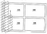
도 13의 처리 유닛은 도 14A 및 도 14B에 각각 도시되는 바와 같이 수평으로 또는 수직으로, 즉, 복수의 방식으로 배향될 수 있다.The processing unit of Fig. 13 can be oriented horizontally or vertically, that is, in a plurality of ways, as shown in Figs. 14A and 14B, respectively.
도 14A와 14B는 도 13의 처리 유닛의 일례의 배향을 도시한다. 도 14A에서는 처리 유닛이 수평으로 배열되며, 도 14B에서는 처리 유닛이 수직으로 배열된다.14A and 14B show an example orientation of the processing unit of Fig. In Fig. 14A, the processing units are arranged horizontally, and in Fig. 14B, the processing units are arranged vertically.
도 15A와 15B는 종래의 단일 플랫베드 머신(도 15A)과, 일실시예에 따른 원통형 머신(도 15B)에 요구되는 플로어 공간의 비교도이다. 도시되는 바와 같이, 단일한 장비는 트랙을 따라 위치하고 로봇을 구비한 종래의 플랫베드 장비에 비해, 트랙에 설비된 실린더 스테이지를 이용하여 수배 작을 수 있다. 도 15A와 15B는 원통형 스테이지에 기초한 장비로 공장을 짓는 것을 도시하며, 운영자들의 머리 위에서 진행하는 트랙들이 장비에 대한 접근가능성과 서비스성질을 향상시킨다. 공장 내 천정에서 바닥까지 공기 흐름 때문에, 처리 트랙과 처리 트랙에 실린 소재들이 위쪽으로부터의 오염에서 보호받게 된다. 추가적으로, 원통형 스테이지를 이용할 때, 일실시예에 따르면, 오염의 근원(가령, 사람)을 처리 영역 아래로 위치하게 할 수 있다.15A and 15B are comparative diagrams of floor space required for a conventional single flatbed machine (Fig. 15A) and a cylindrical machine according to an embodiment (Fig. 15B). As shown, a single piece of equipment can be several times smaller, using a cylinder stage mounted on a track, as compared to conventional flatbed equipment located along a track and equipped with robots. Figures 15A and 15B illustrate building a factory with equipment based on a cylindrical stage, with tracks traveling on the heads of operators improving accessibility and serviceability of the equipment. Because of the airflow from the ceiling to the floor in the plant, the materials on the treatment tracks and treatment tracks are protected from contamination from above. Additionally, when using a cylindrical stage, according to one embodiment, a source of contamination (e.g., a person) may be positioned below the processing region.
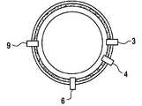
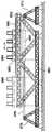
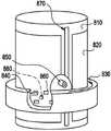
도 16은 실린더의 일실시예의 단면도다. 실린더는 비교적 뻣뻣한 편이고 경량이다. 도 16에 도시되는 바와 같이, 실린더는 베어링에게로 뻗어가는 중앙 튜브(1412)를 포함한다. 튜브(1412)는 축으로 작용하고 이 축 둘레로 실린더가 회전할 수 있다. 튜브(1412)는 알루미늄, 강철, 합금, 등등으로 구성될 수 있다. 실린더는 축(1406) 둘레 중앙에 위치한 큰 튜브일 수 있고, 내부 벽(1418)들의 웹(web)을 이용하여 앵커링될 수 있다. 내부 벽(1418)들은 알루미늄으로 구성될 수 있다. 가령, 알루미늄 스트럿(aluminium struts)으로 구성될 수 있다. 내부 벽(1418)들은 실린더 온도 제어를 위해 공기를 공급하는 부분들을 형성할 수 있다.16 is a cross-sectional view of one embodiment of a cylinder. The cylinder is relatively stiff and lightweight. As shown in FIG. 16, the cylinder includes a
제 2 튜브(1416)가 튜브 외측에 배열되어 실린더 표면을 형성할 수 있다. 제 2 튜브(1416)는 가령, 알루미늄, 티타늄, 스틸, 합금 물질 등으로 구성될 수 있고, 두께가 10mm 정도이다. 표면층(1410)과 제 2 튜브(1416) 간의 공간은 구획들로 나누어져서, 실린더에 소재를 클램핑하기 위해 진공을 만드는 데 사용될 수 있다. 표면층(1410) 두께는 약 4mm다. 표면층은 다공질화되어 진공을 위한 경로를 만들 수 있다.A
실린더의 표면은 여러가지 동작을 위해 서로 다르게 구성될 필요가 있다. 예를 들어, 테플론 코팅된 스테이지들이 당 분야에서 비활성인 점, 세정이 용이한 점, 그리고 스크래치가 없는 점 등의 요인때문에 잘 알려져 있다. 광학적 기록이나 광학적 판독을 위해서는, 실린더 표면으로부터의 반사, 투명한 소재의 뒷면으로부터의 반사, 그리고, 이들 간의 간섭 효과 등이 바람직하지 못할 수 있다. 특히, 레이저 광이 사용될 때 바람직하지 못할 수 있다. 최종 제품에 나타날 수 있는 뉴튼 링(Newton rings)을 위해 세심한 설계가 요구된다. 비-반사형 실린더가 이러한 뉴튼 링들을 처방할 수 있다. 가령, 레이저 파장에 대해 반사율이 낮은 애노드화된 티타늄으로부터 생성된 실린더가 비-반사형 실린더로 사용될 수 있다.The surface of the cylinder needs to be configured differently for various operations. For example, Teflon coated stages are well known for their inertness in the art, ease of cleaning, and absence of scratches. For optical writing or optical reading, reflection from the cylinder surface, reflection from the back surface of the transparent material, and interference effect between them may not be desirable. In particular, it may be undesirable when laser light is used. Careful design is required for Newton rings that may appear in the final product. Non-reflective cylinders can prescribe these Newton rings. For example, a cylinder produced from an anodized titanium having a low reflectance for a laser wavelength can be used as a non-reflective cylinder.
대안으로, 실린더 표면의 한 점에서 다른 점까지 상태가 급속하게 변하도록 실린더 표면의 표면 러프니스 또는 프로파일이 구성될 수 있다. 실린더는 기판을 일부 지점에서만 터치할 수 있고, 이 지점들은 비교적 적은 수일 수 있고 임의적으 로 분포될 수 있다.Alternatively, the surface roughness or profile of the cylinder surface may be configured such that the condition rapidly changes from one point to another on the cylinder surface. The cylinder can touch the substrate only at some points, and these points can be relatively small and arbitrarily distributed.
또다른 실시예에서, 실린더는 습식의 외양을 가지는 표면으로 덮힐 수 있다. 가령, 액체나 점성탄성체, 또는 점성 폴리머인 표면으로 덮힐 수 있다. 앞서 설명한 변화하는 반사율은 실린더 외면의 반사로부터 나타나며, 만약 이 표면이 매끄럽고 소재에 가까울 경우, 뉴튼 링에 의해 악화될 수 있다. 본 예에서, 소재와 공기 간에, 그리고 공기와 실린더 간에 분리된 표면들이 존재하지 않는다. 게다가, 소재로부터 실린더까지 직접 단 한개의 단일 인터페이스만이 존재한다. 소재와 실린더 간의 에어 트래핑을 방지하기 위해, 실린더 표면 물질은 점성의 소프트한 폴리머층이나 얇은 점성탄성층처럼, 탄성을 어느정도 지녀야 한다.In yet another embodiment, the cylinder may be covered with a surface having a wet appearance. For example, a liquid, a viscous elastic, or a viscous polymer. The varying reflectance described above appears from the reflection of the outer surface of the cylinder and can be exacerbated by Newton rings if the surface is smooth and close to the material. In this example, there are no separate surfaces between the material and the air and between the air and the cylinder. In addition, there is only one single interface directly from the material to the cylinder. In order to prevent air trapping between the material and the cylinder, the surface material of the cylinder must have some elasticity, such as a soft, soft polymer layer or a thin viscous elastic layer.
소재가 실린더에 롤링되기 때문에, 접촉이 이루어지기 전에 에어가 푸쉬될 수 있고, 거품없이 연속적인 광학적 접촉이 달성될 수 있다. 마찬가지로, 기판이 언로딩될 때 점성 표면으로부터 깨끗하게 표면이 벗겨질 수 있다. 실린더 표면은 입자들을 줏을 수 있지만, 클리닝 표면에 대한 롤링이나 스위핑에 의해 오염 및 입자로부터 실린더 표면이 주기적으로 세정될 수 있다.Since the material is rolled onto the cylinder, air can be pushed before contact is made, and continuous optical contact without bubbles can be achieved. Likewise, when the substrate is unloaded, the surface can be cleanly removed from the viscous surface. The surface of the cylinder can be focused on particles, but the surface of the cylinder can be cleaned from contamination and particles by rolling or sweeping against the cleaning surface.
도 16의 실린더의 길이는 약 2m이고, 실린더의 공진 주파수는 휨 모드에서 약 500Hz다. 공진 주파수는 실린더의 스티프니스(stiffness)를 측정하는 데 사용될 수 있다. 고속 동작의 경우, 조정가능한 밸런스 웨이트가 여러가지 글래스 두께 사이에서 웨이트 차이를 보정하는 데 사용될 수 있다.The length of the cylinder in Fig. 16 is about 2 m, and the resonance frequency of the cylinder is about 500 Hz in the bending mode. The resonant frequency can be used to measure the stiffness of the cylinder. In the case of high-speed operation, an adjustable balance weight can be used to correct the weight difference between various glass thicknesses.
도 17은 일실시예에 따라 조정가능한 밸런스 웨이트를 포함하는 실린더를 도시한다. 도시되는 바와 같이, 실린더(1500)는 조정가능한 또는 고정된 복수의 웨이 트(1502, 1504, 1506)를 포함할 수 있다. 도 17에서는 세개의 조정가능한 웨이트만을 도시하고 있으나, 임의의 수의 조정가능한 웨이트가 사용될 수 있다. 웨이트(1502)가 고정될 수 있고, 웨이트(1504, 1506)는 액츄에이터를 이용하여 실린더(12500)의 중심으로부터 가깝게 또는 멀리 이동하거나 조정될 수 있다. 조정가능한 웨이트(1504, 1506)는 정적 및 동적 밸런싱용으로 사용될 수 있다. 웨이트(1504, 1506)를 조정함으로서, 단면에서의 실린더(1500)의 무게중심은 회전축(1508) 상에 머물게 된다. 웨이트들이 각각의 단부와 한개의 중간 위치에 배열될 경우, 실린더는 제 1 휨 모드에 대해 정적으로 또는 동적으로 밸런싱될 수 있다. 동적 밸런싱은 회전 중 실린더를 휘게 하거나 베어링에 가해지는 가속도 또는 측정된 힘에 기초하여 컴퓨터 제어 하에서 수행될 수 있다.Figure 17 illustrates a cylinder including an adjustable balance weight in accordance with one embodiment. As shown, the
도 18A는 일실시예에 따른 원통형 스테이지의 수평 배향을 도시한다. 도 18B는 일실시예에 따른 원통형 스테이지의 수직 배향을 도시한다. 실린더를 수평으로 로딩할 때(도 18A 참고), 소재를 컨베이어 벨트로부터 취할 수 있다. 실린더를 수직으로 로딩할 때(도 18B 참고), 실린더는 가이드 레일 시스템으로부터 로딩될 수 있다. 수평으로 로딩될 때, 소재는 중력에 의해 제자리에 유지될 수 있다. 중력에 부가하여, 수평으로 로딩된 실린더들은 소재를 제자리에 래칭하기 위해 실린더 상에서 소재의 에지들을 아래로 강제하게 하는 푸셔에 의해 제자리에 유지될 수 있다. 소재들은 그 표면이 실린더 표면을 가깝게 따르는 것을 보장하기 위해 진공에 의해 유지될 수 있다. 소재의 단분에서는 소재의 탄성력이 근원힘이 될 수 있다. 따라서, 소재의 단부에서는 실린더에 견고하게 조여져야 한다. 소재의 에지를 캡처 하거나 릴리스하기 위해 제어되는 래치가 사용될 수 있다. 에지가 언로딩을 위해 릴리스될 때, 푸셔는 힘을 넘겨서 소재의 단부를 따르게 되고 이때 언롤링된다. 푸셔는 접촉 타입일 수도 있고 비접촉식일 수도 있다.18A shows the horizontal orientation of a cylindrical stage in accordance with one embodiment. Figure 18B shows the vertical orientation of a cylindrical stage in accordance with one embodiment. When loading the cylinder horizontally (see Fig. 18A), the material can be taken from the conveyor belt. When vertically loading the cylinder (see FIG. 18B), the cylinder can be loaded from the guide rail system. When loaded horizontally, the workpiece can be held in place by gravity. In addition to gravity, horizontally loaded cylinders can be held in place by a pusher that forces the edges of the material down on the cylinder to latch the material in place. The materials can be held by vacuum to ensure that the surface follows the cylinder surface closely. In a single section of the material, the elastic force of the material can be the source force. Therefore, the end of the material must be tightly fastened to the cylinder. A latch controlled to capture or release the edge of the material may be used. When the edge is released for unloading, the pusher follows the end of the material with the force being released and is then unrolled. The pusher may be of a contact type or of a non-contact type.
도 19는 일실시예에 따라 소재에 면하는 다공질 에어 쿠션을 가진 비접촉 푸셔를 도시한다. 도시되는 바와 같이, 비접촉 푸셔(1702)는 소재가 실린더(1700)에 로딩되는 곳에 배열된다. 또다른 비접촉 푸셔(1704)는 소재가 실린더(1700)로부터 언로딩되는 곳에 배열된다.Figure 19 illustrates a non-contact pusher having a porous air cushion facing a material in accordance with one embodiment. As shown, the
일실시예들은 종래의 장비보다 작고 가볍고 정밀한 디스플레이나 솔라 패널을 제작하기 위한 장비를 만드는 방법 및 장치를 제공한다. 실린더 스테이지를 이용하는 실시예들의 응용성과 유용성은, 글래스 크기보다 훨씬 작은 실린더 상에 글래스가 롤링될 수 있는 지 여부에 따라 좌우될 수 있다. 일실시예들은 직경 1m의 실린더를 이용할 수 있다. 글래스의 강도는 응력을 받은 상태에서 글래스 상에서 전파될 수 있는 글래스 표면의 임의적인 마이크로크랙들에 의해 저하될 수 있다. 마이크로크랙들이 글래스의 강도를 저하시킬 경우, 글래스의 허용가능한 응력은 글래스 면적의 함수일 수 있다. 글래스를 조심스럽게 취급할수록, 손상된 크랙을 가진 글래스의 확률이 작아진다. 불량 확률은 크랙을 전파시키는 데 필요한 에너지같은 글래스의 성질에도 또한 좌우된다. 디스플레이 제작에 사용되는 글래스는 이러한 성질을 고려하여 개발되고 있으며, 표준 글래스보다 강도가 높은 편이다. 글래스를 코팅시킴으로서 불량 확률을 낮출 수도 있다. 코팅은 마이크로크랙들을 브리징(bridging)할 수 있다. 글래스 시트 파괴의 일부분은 글래스 시트의 에지에서 시 작된다. 이 에지들은 글래스를 커팅할 때 또는 취급 중에 손상될 가능성이 높다. 글래스 시트는 스코어링되어 적정한 크기로 커팅될 수 있다. 일례의 스코어링 프로세스(scoring process)에서, 롤러는 스코어링 라인에서 미세한 크랙들을 생성한다. 글래스가 스코어링 라인에 대해 나중에 휘게될 경우, 글래스가 파괴될 수 있다. 그러나, 롤러를 이용한 스코어링은 커팅 에지에서 작은 크랙들을 남길 수 있다. 이러한 크랙들은 글래스에 응력이 가해질 때 글래스 내로 전파할 수 있고, 표면 손상에 비해 낮은 스트레스 레벨에서도 파괴를 일으킬 수 있다. 스코어링은 레이저나 다이아몬드를 이용하여 수행될 수 있다. 레이저 스코어링은 당 분야에 잘 알려져 있으며, 크랙이 없는 에지를 생성할 수 있다. 레이저 스코어링이 당 분야에 잘 알려져 있기에, 추가적인 설명은 생략한다.One embodiment provides a method and apparatus for making a device for making a small, light and precise display or solar panel than conventional equipment. The applicability and usability of embodiments employing a cylinder stage may depend on whether the glass can be rolled on a cylinder much smaller than the glass size. One embodiment may utilize a cylinder with a diameter of 1 m. The strength of the glass can be reduced by any microcracks on the glass surface that can propagate on the glass under stressed conditions. When microcracks degrade the strength of the glass, the allowable stress of the glass may be a function of the glass area. The more careful handling of the glass, the lower the probability of glass with damaged cracks. The failure probability also depends on the nature of the glass, such as the energy required to propagate the cracks. The glass used in the display production is being developed in consideration of this property, and it has a higher strength than the standard glass. By coating the glass, the probability of failure can be lowered. The coating is capable of bridging micro cracks. Part of the glass sheet breakage starts at the edge of the glass sheet. These edges are most likely to be damaged during cutting or handling of the glass. The glass sheet can be scored and cut to the proper size. In an exemplary scoring process, the rollers produce fine cracks in the scoring line. If the glass bends later with respect to the scoring line, the glass may be destroyed. However, scoring with rollers can leave small cracks at the cutting edge. These cracks can propagate into the glass when the glass is stressed and can cause failure at lower stress levels than surface damage. Scoring can be performed using lasers or diamonds. Laser scoring is well known in the art and can produce crack-free edges. Since laser scoring is well known in the art, further explanation is omitted.
도 20은 단축방향 휜 글래스의 표면의 응력과, 글래스 두께, 그리고 실린더 직경 간의 관계를 나타내는 실린더 직경 대 글래스 두께의 그래프다. 글래스는 0.5 ~ 0.7mm 의 두께를 가질 수 있다. 도 20의 점선은 0.5mm, 0.62mm. 그리고, 0.7mm의 글래스 두께를 표시한다. 도 20에 도시되는 바와 같이, 1m 직경의 실린더는 0.7mm 두께의 글래스에 대해 50MPa을 제공하고, 0.5mm 두께의 글래스에 대해 37MPa을 제공한다. 글래스는 최대 3095mm 길이를 가질 수 있다. 가령, 1.0m 직경의 실린더를 필요로한다. 본 발명의 일실시예에 따르면, 1m 직경에 대해 휘어질 때 글래스 파괴 확률은 로딩 동작 당 1/100,000의 수준이어야 한다. 이 확률을 보장하기 위해, 글래스 시트는 로딩 이전에, 약간 더 높은 응력으로 미리 응력처리될 수 있다. 마이크로크랙들을 가진 글래스 시트들은 사전응력처리 중 파괴될 수 있고, 따 라서 제거될 수 있다. 손상없이 사전응력 테스트를 거친 글래스는 처리과정 중 파괴될 확률이 적다.20 is a graph showing the relationship between the stress on the surface of uniaxial warp glass, the glass thickness, and the cylinder diameter versus the cylinder diameter versus glass thickness. The glass may have a thickness of 0.5 to 0.7 mm. The dotted lines in Fig. 20 indicate 0.5 mm, 0.62 mm. Then, a glass thickness of 0.7 mm is displayed. As shown in Fig. 20, a 1 m diameter cylinder provides 50 MPa for a 0.7 mm thick glass and 37 MPa for a 0.5 mm thick glass. The glass can have a maximum length of 3095 mm. For example, a 1.0 m diameter cylinder is required. According to one embodiment of the present invention, the probability of glass breakage when bent against a 1 m diameter should be at a level of 1 / 100,000 per loading operation. To ensure this probability, the glass sheet can be pre-stressed with a slightly higher stress prior to loading. Glass sheets with micro-cracks can be destroyed during pre-stressing and can therefore be removed. Pre-stressed glass without damage is less likely to be destroyed during processing.
도 21A와 21B는 일실시예에 따른 사전응력 장치들을 도시한다.Figures 21A and 21B illustrate pre-stressing devices according to one embodiment.
도 21A에 따르면, 롤러를 이용하여 브리틀한 소재(가령, 글래스 시트)에 사전응력(pre-stress)이 가해진다. 예를 들어, 도 21A에 도시되는 바와 같이 롤러를 통해 소재에 응력이 공급될 수 있고, 제어되는 방향으로 소재에 휨 응력이 가해질 수 있다. 도 21B는 비접촉식 에어 쿠션으로 롤러를 대체한 유사한 장치를 도시한다. 도 21A와 21B가 양쪽으로 대칭인 휨 모멘트를 도시하고 있지만, 롤러간 거리를 변화시킴으로서(또는 에어 패드들 간 거리를 변화시킴으로서), 응력이 비대칭이 될 수 있다.According to Fig. 21A, a pre-stress is applied to a material (e.g., a glass sheet) that has been brittle using a roller. For example, as shown in Fig. 21A, stress can be applied to the material through the roller, and bending stress can be applied to the material in the controlled direction. Figure 21B shows a similar device replacing the roller with a non-contact air cushion. Although Figures 21A and 21B illustrate bending moments that are symmetrical on both sides, the stress can be asymmetric by changing the inter-roller distance (or by changing the distance between the air pads).
글래스가 취급되고 있을 때 에지를 손상으로부터 보호하기 위해, 도 22B-22D에 도시되는 바와 같이 에지가 코팅될 수 있고, 글래스 시트를 취급하는 로보트들이 에지로부터 수밀리미터 내에서 밴드와 익스트림 에지를 터치하지 않도록 설계될 수 있다. 글래스 시트 상의 취급 밴드는 가령, 20mm 폭을 가질 수 있고, 실제 에지는 도 22A에 도시되는 바와 같이 취급 영역으로부터 배제될 수 있다. 에지는 (도 22C의 취급 영역을 포함하여) 도 22B에 도시되는 바와 같이 취급 영역 외부에서 코팅될 수 있고, 또는 전체 표면이 도 22D에 도시되는 바와 같이 코팅될 수 있다.To protect the edge from damage when the glass is being handled, the edges can be coated as shown in Figures 22B-22D, and the robots handling the glass sheet do not touch the band and extreme edges within a few millimeters from the edge . The handling band on the glass sheet may, for example, have a width of 20 mm and the actual edge may be excluded from the handling area as shown in Fig. 22A. The edge may be coated outside the handling area as shown in Figure 22B (including the handling area of Figure 22C), or the entire surface may be coated as shown in Figure 22D.
도 23A-23D는 일실시예에 다른, 글래스의 내측부와 동일한 레벨에 놓인 에지에서 응력이 형성되는 것을 방지하는 방법을 제시한다. 글래스가 휘어질 때, 외면이 팽창될 수 있고, 인장 응력을 받을 수 있다. 이때 내면은 압축될 수 있고 압축 응력을 받을 수 있다. 글래스 시트 내부에는 휨으로 인한 응력의 변화가 나타나지 않는 위치가 존재한다. 이를 중립층(neutral layer)이라 부른다. 중립층이 외면에 더 가깝도록 글래스 에지가 수정될 경우, 에지 근처의 인장 응력의 크기가 감소될 수 있다. 도 23A에서, 글래스는 압축으로부터 응력이 생성되는 경우에 비교적 날카로운 각이 생성되도록 하는 각도에서 절단될 수 있고, 응력이 인장 응력일 때 둔각이 생성되도록 하는 각도에서 절단될 수 있다. 둔각은 크랙을 일으킬 가능성이 적고, 글래스 시트에 대한 허용가능한 응력이 증가할 수 있다. 절단 측부와 외면 간의 코너가 글래스 커팅으로부터 임의의 크랙과 함께 제거될 수 있도록, 에지가 성형될 수 있다(가령, 그라인딩되거나 폴리싱될 수 있다). 도 23C에 도시되는 바와 같이, 에지를 휘게하는 글래스 상의 응력층을 형성함으로서 또는 열이나 레이저를 이용하여 에지가 내측으로 휘어질 수 있다. 마지막으로, 도 23D에 도시되는 바와 같이, 글래스는 클램핑 힘에 의해 내측으로 힘을 받을 수 있다. 가령, 내측에 진공이 형성되거나, 외측에 기계적 압력이 주어질 수 있다.Figures 23A-23D illustrate a method for preventing stress from forming at edges lying on the same level as the medial side of the glass, different from the one embodiment. When the glass is warped, the outer surface can expand and can be subjected to tensile stress. At this time, the inner surface can be compressed and can receive compressive stress. There is a position in the glass sheet where there is no change in stress due to warping. This is called the neutral layer. When the glass edge is modified such that the neutral layer is closer to the outer surface, the magnitude of the tensile stress near the edge can be reduced. In Fig. 23A, the glass can be cut at an angle to cause a relatively sharp angle to be produced when stress is generated from compression, and at an angle such that an obtuse angle is generated when the stress is tensile. The obtuse angle is less likely to cause cracking, and the allowable stress on the glass sheet can be increased. The edge can be shaped (e.g., can be ground or polished) so that the corner between the cut side and the outer surface can be removed with any cracks from the glass cut. As shown in FIG. 23C, the edges can be bent inward by forming a stress layer in the glass that warps the edges, or by using heat or a laser. Finally, as shown in Figure 23D, the glass can be forced inward by the clamping force. For example, a vacuum may be formed inside, or mechanical pressure may be given to the outside.
도 24A와 24B는 일실시예에 따라 글래스 에지를 커팅하는 방법들을 제시한다.. 글래스는 종래의 방식으로 스코어링될 수 있고, 커팅을 절단할 때 전단력이 가해질 수 있다. 휨과 전단력의 조합에 의해 결사진 절단면이 제공된다.24A and 24B illustrate methods of cutting a glass edge in accordance with one embodiment. Glass can be scored in a conventional manner and a shearing force can be applied when cutting the cut. A combination of bending and shearing forces provides a cut surface.
처리 단계들 중, 글래스 상에 브리틀한 필름이 존재할 때, 브리틀한 필름이 휨의 결과로 크랙되지 않음을 보장하는 것이 매우 중요하다. 도 25A-25C는 브리틀한 필름에 크랙들이 어떻게 형성되는 지를 보여준다. 도 25A에 제시되는 바와 같이, 글래스는 위와 아래에 필름을 가질 수 있고, 중간에 중립층이 형성될 수 있다. 소정 크기의 휨(가령, 응력변형)에서, 도 25B에 도시되는 바와 같이 필름의 결함으로부터 크랙들이 전파되기 시작한다. 글래스가 휘어질 때, 더 많은 크랙들이 평행선들을 따라 전파하며, 필름이 파괴될 수 있다. 이는 ITO, 실리콘, 실리콘다이옥사이드같은 필름에서 1% 이상의 응력변형시 통상적으로 나타난다. 짧은 크랙의 전파를 정량화하기는 매우 어려울 수 있고, 필름의 성질, 필름 및 글래스의 영 상수 간의 매칭, 필름의 접착도, 필름 내 결함의 분포 등등에 좌우될 수 있다. 그러나, 글래스가 휘어지지 않을 때 필름 내 내재 응력(built-in stress)을, 글래스가 휘어질 때 필름의 응력에 대해 비교함으로서 안전한 레벨의 응력을 추정할 수 있다. 내재응력은 약 0.1~0.5%의 응력변형에 해당하며, 글래스의 휨은 통상적으로 0.08%로 기여한다. 그 결과, 휨에 의해 야기되는 응력은 필름 내 크랙의 형성에 그다지 큰 영향을 미치지 않는다. 본 예에서, 휨으로부터 부가된 응력은 글래스가 펼쳐지거나 압축될 때 발생할 수 있다. 도 25C는 압축 응력 하에서 글래스 버클링 파괴의 예를 도시한다.Of the processing steps, it is very important to ensure that when a brittle film is present on the glass, the brittle film is not cracked as a result of bending. Figures 25A-25C show how cracks are formed on the brittle film. As shown in Fig. 25A, the glass may have a film above and below, and a neutral layer may be formed in between. At a predetermined amount of warpage (e.g., strain), cracks begin to propagate from the defects of the film as shown in Fig. 25B. As the glass bends, more cracks propagate along the parallel lines and the film can break. This is commonly seen in strains of 1% or more in films such as ITO, silicon, and silicon dioxide. Quantifying the propagation of short cracks can be very difficult and can depend on the nature of the film, the matching between the film and the zero constant of the glass, the adhesion of the film, the distribution of defects in the film, and so on. However, it is possible to estimate a safe level of stress by comparing the built-in stress in the film when the glass is not bent, against the stress of the film when the glass is bent. The inherent stress corresponds to a stress strain of about 0.1-0.5%, and the deflection of the glass typically contributes 0.08%. As a result, the stress caused by the warp does not significantly affect the formation of cracks in the film. In this example, stresses added from warpage can occur when the glass is unfolded or compressed. 25C shows an example of glass buckling failure under compressive stress.
도 26은 ITO 필름에서 응력변형과 함께 저항이 어떻게 증가하는 지를 도시한다. 이 내용은 Y.Leterrier를 대표 저자로 하는 "Mechanical properties of transparent functional thin films for flexible displays", 46th Annual Technical Conference Porceedings (2003) ISSN 0737-5921 에 개시된 내용에 해당한다. 날카로운 증가는 평행한 긴 크랙들의 발전을 나타내고, 날카로운 니(knee) 부분 이전의 완만한 증가는 결함 주위로 짧은 크랙들이 형성됨을 나타낸다. 이 그래프는 브리틀한 ITO 필름으로 덮힌 플라스틱 기판에 적용될 수 있고, 글래스 상의 ITO 필름의 거동을 표시하는 예로 취급될 수 있다.Fig. 26 shows how the resistance increases with strain in the ITO film. This content corresponds to the disclosure of "Mechanical properties of transparent functional thin films for flexible displays", 46th Annual Technical Conference Papers (2003) ISSN 0737-5921, by Y. Leterrier. A sharp increase indicates the development of parallel long cracks, and a gradual increase prior to the sharp knee portion indicates that short cracks are formed around the defect. This graph can be applied to a plastic substrate covered with a brittle ITO film and can be treated as an example of the behavior of an ITO film on a glass.
기판은 글래스, 플라스틱, 스틸, 페이퍼, 또는 그외 다른 시트 물질일 수 있다. 예를 들어, 기판이 디스플레이-그레이드 글래스일 경우, 기판이 약 4ppm/K 의 열팽창계수를 가질 수 있다. ITO같은 브리틀한 필름은 더 높은 열팽창계수를 가질 수 있다. 고온에서 필름이 증착될 경우, 미스매치에 의해 필름에는 냉각 이후 인장 응력이 커지게 된다. 실린더 외측에 위치한 소재의 휨은 휘어진 상태일 때 인장 응력을 부가하게 된다. 이 스테이지는 온도에 의해 제어될 수 있어서, 높은 정밀도로 스테이지의 형태와 크기를 제어할 수 있다. 글래스가 실린더에 롤링될 때, 또는 플랫 베드 상에 놓여 클램핑될 때 글래스는 이 스테이지의 온도에 적응되거나, 글래스가 로딩되기 전에 온도에 따라 수축되거나 팽창될 수 있다. 이러한 수축이나 팽창은 온도 변화에 의해 야기되는 응력을 완화시키는, 스테이지와 소재 간의 스케일 및 크립(creep)의 변화같은 문제점들을 일으킬 수 있다.The substrate may be glass, plastic, steel, paper, or other sheet material. For example, if the substrate is a display-grade glass, the substrate may have a thermal expansion coefficient of about 4 ppm / K. Brittle films such as ITO may have a higher coefficient of thermal expansion. When a film is deposited at a high temperature, the tensile stress is increased after cooling by the mismatch. The flexure of the material located outside the cylinder adds tensile stress when it is bent. This stage can be controlled by temperature, so that the shape and size of the stage can be controlled with high precision. The glass can be adapted to the temperature of the stage when the glass is rolled into the cylinder, or clamped on the flatbed, or it can contract or expand depending on the temperature before the glass is loaded. Such shrinkage or expansion can cause problems such as a change in the scale and creep between the stage and the workpiece, which relaxes the stress caused by the temperature change.
일실시예에 따르면, 소재 표면 위 임의의 지점의 어레이에서 온도가 측정될 수 있고, 소재의 온도 변형이 연산될 수 있으며, 좌표계가 교정될 수 있다. 본 예의 실시예는 소재가 비교적 빠르게 이동하는 도 61A와 61B에 도시되는 바와 같이, "로우-풋프린트(low-footprint)"에 적합할 수 있다.According to one embodiment, the temperature can be measured in an array at any point on the work surface, the temperature variation of the work can be calculated, and the coordinate system can be calibrated. The embodiment of the present example may be suitable for a "low-footprint" as shown in Figures 61A and 61B where the material moves relatively quickly.
또다른 실시예에서, 기판은 시스템의 스테이지로 로딩 및 클램핑되기 전에 강제적으로 템퍼링될 수 있다. 소재를 템퍼링하는 시스템은 필터링된 템퍼링 에어플로를 가져서, 기판이 고체 구조를 터치하지 않는 것을 보장할 수 있다. 강한 에어플로로, 기판은 0.7mm 두께보다 작거나 같은 기판의 열에 대한 짧은 확산 시간으 로 인해 수초 내에서 템퍼링될 수 있다.In yet another embodiment, the substrate can be forcibly tempered prior to loading and clamping to the stage of the system. The system for tempering the material may have a filtered tempering air flow to ensure that the substrate does not touch the solid structure. With strong airflow, the substrate can be tempered in a matter of seconds due to the short diffusion time for the heat of the substrate less than or equal to 0.7 mm thick.
도 27은 실린더에 로딩되기 전에 소재의 온도를 제어하는 시스템을 도시한다. 소재(2518)는 컨베이어 벨트(2520) 상에서 이동할 수 있고, 온도 안정화 장치(2500) 하에서 통과할 수 있다. 이때, 주어진 온도의 필터링된 에어가 강제 공급된다.Figure 27 shows a system for controlling the temperature of a workpiece before it is loaded into the cylinder. The
도 27과 관련하여, 팬이나 송풍기(2502, 2504)가 비교적 고압의 에어플로를 발생시키며, 이러한 에어플로는 입자 필터(2508)와 열 교환기(2506)에 의해 필터링되고 템퍼링된다. 이 장치(2500)는 소재(2518)와 직접 접촉하지 않을 수 있고, 대신에, 에어가 이 장치에 공급되어 장치(2500)와 소재(2518) 간의 갭(2514)에 에어 출력을 항상 도출할 수 있다. 소재(2518)가 실린더(2516)보다 고온일 경우, 열 교환기(2506)가 소재(2518)의 온도를 낮출 수 있다.27, fans or
상술한 바와 같이, 장비의 여러 다른 요소들은 플레이트 상의 위치를 참조로 하여 공통 좌표계를 가질 필요가 있다. 플랫폼을 이용할 때, 일실시예에 따르면(가령, 측정 및 패턴처리 실시예), 3미크론 이상의 총 정확도와, 1미크론 이상의 복수의 툴들 간의 차이 정확도를 가지는 고정밀 좌표계가 필요할 수 있다.As described above, various other elements of the apparatus need to have a common coordinate system with reference to the position on the plate. When using a platform, according to one embodiment (e.g., a measurement and pattern processing embodiment), a high precision coordinate system with a total accuracy of 3 microns or more and a difference accuracy between a plurality of tools of 1 micron or more may be required.
일실시예에 따르면, 복수의 툴들 간의 차이 정확도는 100 나노미터 이상일 수 있다. 이러한 수준의 정확도는 의도적인 정확도 구조의 결과다. 표준화된 공통 좌표계를 생성하는 것은 여러개의 요소들을 가질 수 있다. 즉, 스테이지 좌표계의 생성, 스테이지 좌표계에 대한 툴의 정렬, 스테이지 상에서의 소재 정렬, 클램핑에 의해 유도되는 왜곡의 교정, 온도 교정, 또는 처리 왜곡에 대한 교정을 가질 수 있 다.According to one embodiment, the difference accuracy between the plurality of tools may be greater than 100 nanometers. This level of accuracy is the result of an intentional accuracy structure. Creating a standardized common coordinate system can have several elements. That is, it can have the creation of a stage coordinate system, the alignment of the tool with respect to the stage coordinate system, the alignment of the material on the stage, the correction of distortion induced by clamping, the temperature correction, or the processing distortion.
도 28A와 28B는 종래의 원통형 좌표계를 도시한다. 그러나, 이 좌표계에 요구되는 정확도는 트랜지스터 어레이와 칼라 필터 간에 그리고 플랫베드 시스템에서 생성되는 다른 층들과의 더 작은 오버레이 에러를 보장하기 위해, 플랫한 상태에서 글래스의 정확도에 해당한다. 통상적으로, 이 좌표계는 플랫한 상태에서 규정되지만 휨에 의해 왜곡될 수도 있다.28A and 28B show a conventional cylindrical coordinate system. However, the accuracy required for this coordinate system corresponds to the accuracy of the glass in a flat state, to ensure a smaller overlay error between the transistor array and the color filter and with other layers created in the flatbed system. Normally, this coordinate system is defined in a flat state, but may be distorted by bending.
도 29는 일실시예에 따른 원통형 좌표계를 도시한다. 도시되는 바와 같이, 좌표축은 실린더 스테이지의 방향에 대해 규정되고 명칭을 부여받는다. 예를 들어, 축 방향은 툴 방향이라 불린다. 왜냐하면, 이 축을 따라 툴이 툴바 상에서 슬라이되기 때문이다. 접선축은 드럼축이라 불린다. 반경방향 축은 포커스 축이라 불린다.Figure 29 shows a cylindrical coordinate system according to one embodiment. As shown, the coordinate axes are defined and named for the orientation of the cylinder stage. For example, the axial direction is called the tool direction. This is because the tool is slid on the toolbar along this axis. The tangential axis is called the drum axis. The radial axis is called the focus axis.
도 30은 일실시예에 따른 실린더 상에 좌표계를 구축하는 장치를 제시한다. 도시되는 바와 같이, 각도 인코더 디스크(2802)가 실린더(2804)와 함께 회전하며, 선형 인코더(2806)가 툴축을 따라 배열될 수 있다. 툴바(2808)는 각도 인코더 디스크(2802)를 기준으로 하며, 툴에 의해 사용되는 스케일을 제공한다. 각도 인코더 디스크(2802)는 회전축 위치의 불확실성, 각도 코드의 비선형성, 또는 도 31A에 도시되는 바와 같은 노이즈 등등과 같은 에러의 문제점을 내포하고 있다.30 shows an apparatus for constructing a coordinate system on a cylinder according to an embodiment. As shown, the
도 31B는 일실시예에 따라 인코더 디스크에 대한 각도 측정을 개선시키는 장치를 도시한다. 인코더 디스크당 두개 이상의 판독 헤드가 사용될 수 있고, 판독치들 간의 합과 차로부터 각도가 계산될 수 있다. 도 31B에 도시되는 바와 같이, 클 럭 위치 3, 4, 6, 9에서 판독 헤드의 경우, 회전축이 인코더의 축 중앙에 위치하지 않을 경우, 에러가 사인파-형태의 에러일 수 있다. 3시와 9시 사이의 차이는 윗방향 및 아랫방향의 축의 움직임을 식별한다. 3시와 9시 사이의 평균이 6시에 비교될 때, 사인파 에러 성분이 수평 방향으로 축의 움직임을 제공할 수 있다. 축이 중앙에 위치하지 않는다고 결정될 때, 3시와 4시 간의 차이가 짧은 주기의 비선형 에러의 표시로 사용될 수 있다. 마지막으로, 실린더의 각도로 판독 헤드들 사이에서 움직이는 동일한 에러를 식별함으로서 평균치와 통계치에 의해 임의-노이즈형 에러들이 감소될 수 있다. 상술한 방법들을 이용하여, 수십 나노미터 수준의 실린더표면 상의 에어를 가진 좀 더 신뢰성있는 각도 스케일을 구축하는 데 상용 각도 인코더가 사용될 수 있다.Figure 31B illustrates an apparatus that improves the angular measurement for an encoder disk in accordance with one embodiment. Two or more readheads may be used per encoder disk, and an angle may be calculated from the sum and the difference between the readings. As shown in FIG. 31B, in the case of a readhead at
도 32는 일실시예에 따라 축방향 움직임을 수행하는 장치를 제시한다. 장치(3000)는 간섭계(3004)를 포함할 수 있다. 간섭계(3004)는 툴(3002)과 인코더 디스크(3006) 간의 차이 움직임을 수행할 수 있다.32 illustrates an apparatus for performing axial motion in accordance with one embodiment.
도 33은 일실시예에 따라 축방향 측정을 수행하는 장치를 도시한다. 도 33과 관련하여, 고정된 구조(3106) 상의 이너시아 센서(3102)와 실린더(3100) 상의 이너시아 센서(3104)에 의해 각도가 측정될 수 있다. 센서(3102)에 대한 센서(3104)의 위치를 제공하기 위해 가속도 차이가 두배로 배가될 수 있다. 실린더의 회전 속도에 따라, 도 32 나 도 33의 장치가 더 우수한 정확도를 제공할 수 있다.33 illustrates an apparatus for performing axial measurement in accordance with one embodiment. 33, the angle can be measured by the
도 34는 일실시예에 따라 축방향 측정을 수행하기 위한 또다른 장치를 도시한다. 도시되는 바와 같이, 도 34의 장치는 실린더(3206)의 각각의 둘레에 위치한 한개 이상의 선형 인코더(3204)와 조합하여 툴바(3202) 상에 한개 이상의 선형 인코더(3200)를 포함할 수 있다. 도 34의 장치를 이용하여, 실린더(3206)의 중심과 논-라운드니스(non-roundness: 즉, 둥글지 못한 결점)으로부터 발생하는 소정의 에러들이 교정될 수 있다(측정치로부터 배제될 수 있다).34 illustrates another apparatus for performing axial measurement in accordance with one embodiment. As shown, the apparatus of FIG. 34 may include one or more
도 35는 일실시예에 따라 공통 좌표계를 생성 및 이용하는 장치를 도시한다. 도시되는 바와 같이, 실린더(3308)에 룰러(3306)가 부착되어, 기준점이 각각의 툴바(3302)를 지날 때 룰러(3308)의 위치가 카메라(3304)에 의해 픽업될 수 있다. 기준점들은 2차원 표시(가령, 체브론 마크)를 가질 수 있고, 카메라(3304)는 x 및 y 위치를 제공할 수 있다. 동일한 과정이 각각의 툴바(3302)에 대해 수행된 후, 각각의 툴바(3302)는 소재 상의 좌표계를 참조한다.Figure 35 illustrates an apparatus for creating and using a common coordinate system in accordance with one embodiment. As shown, a
소재가 휘어지면, 소재의 외면이 팽창되고 내면은 수축될 수 있다. 중립층은 고체 물질의 균일한 슬랩을 포함할 수 있고, 이는 불변으로 남을 수 있다. 이러한 중립층은 슬랩의 중심에 위치하며, 표면들에서의 수축 및 팽창은 같은 크기, 다른 부호를 가지게 된다.When the material is warped, the outer surface of the material may expand and the inner surface may contract. The neutral layer may comprise a uniform slab of solid material, which may remain unchanged. This neutral layer is located at the center of the slab, with shrinkage and expansion at the surfaces of the same size and different sign.
도 36A와 36B는 일실시예에 따라 소재가 실린더 상에서 롤링되거나 휘어질 때 얻어지는 측정치를 이용하여 플랫한 소재 상의 좌표계를 연산하는 방법을 제시한다. 일실시예에 따르면, 실린더 각도는 중립면을 따르는 위치로 변환될 수 있다. 이를 위해, 각도 리잘버(angle resolver)(가령, 인코더)의 축으로부터의 거리가 소재의 내면 및 외면의 반경 방향 위치 및 공지된 축 위치를 이용하여 연산될 수 있다. 중립층의 로컬 곡률 반경이 연산될 지점 근처의 외면 및 내면의 측정치로부터 도출될 수 있다. 중립층의 로컬 곡률반경은 표면의 팽창을 연산하는 데 사용될 수 있다.36A and 36B illustrate a method of computing a coordinate system on a flat workpiece using measurements obtained when a workpiece is rolled or bent on a cylinder, according to one embodiment. According to one embodiment, the cylinder angle can be converted to a position along the neutral plane. To this end, the distance of the angle resolver (e.g., encoder) from the axis can be calculated using the radial position of the inner and outer surfaces of the workpiece and the known axis position. The local curvature radius of the neutral layer can be derived from measurements on the outer and inner surfaces near the point at which it is to be calculated. The local curvature radius of the neutral layer can be used to calculate the expansion of the surface.
도 36A는 이상적인 경우를 도시하고, 도 36B는 글래스 두께의 변화, 둥글지 않은 실린더, 점들 간에 변화하는 곡률의 중심 등의 요인을 가진 좀 더 현실적인 경우를 도시한다. 실린더 축에 수직인 단면에서 에러가 나타나며, 소재의 두께 변화와 실린더의 곡률은 2차원적 성질을 가져서, 표면에 대한 팽창 텐서로 기여한다. 이 팽창 텐서는 실린더 상에서 롤링될 때 글래스의 왜곡 필드(distortion field)를 얻기 위해 일체화될 수 있다.36A shows an ideal case, and FIG. 36B shows a more realistic case with factors such as a change in glass thickness, a non-rounded cylinder, a center of curvature changing between points, and the like. Errors appear on the cross section perpendicular to the cylinder axis, and the thickness variation of the material and the curvature of the cylinder have two-dimensional properties, contributing to the expansion tensor for the surface. This dilation tensor can be integrated to obtain the distortion field of the glass when it is rolled on the cylinder.
도 36C는 일실시예에 따라 글래스의 내면 및 외면의 위치를 측정하는 장치를 제시한다. 도 36C의 장치는 실린더의 축을 기준으로 할 수 있다. 필름 코팅된 소재를 이용하는 예에서, 필름의 응력은 소재를 자유로운 상태로 휘게할 것이다. 실린더에 클램핑될 때, 곡률은 실린더와 소재 두께에 의해 결정될 수 있다. 그러나, 필름 응력은 소재에 응력을 생성하여, 중립층을 변위시키고 측면 방향 왜곡을 야기할 수 있다. 필름의 응력은 중립층의 연산에 포함될 수 있고, 플랫한 좌표계의 연산을 보상할 수 있다.Figure 36C shows an apparatus for measuring the position of the inner and outer surfaces of a glass according to one embodiment. The apparatus of Figure 36C can be based on the axis of the cylinder. In the example using a film-coated material, the stress of the film will bend the material free. When clamped to the cylinder, the curvature can be determined by the cylinder and the material thickness. However, film stress can create stress in the material, displacing the neutral layer and causing lateral distortion. The stress of the film can be included in the calculation of the neutral layer, and the calculation of the flat coordinate system can be compensated.
도 36D는 표준화된 소재 좌표 x와 y로의 이동 명령이 특정 툴 및 스테이지 좌표로 스테이지 및 툴을 이동시키라는 명령으로 어떻게 변환될 수 있는 지를 상세하게 제시한다. 표준화된 소재 좌표들은 소재가 요망 상태 또는 지정 상태에 있을 때, 또는 나중에 있게 될 때, 소재 상의 좌표에 해당한다. 가령, 섭씨 22도의 균일한 온도에서 플랫한 프론트 사이드에서 응력을 받지 않은 상태의 좌표에 해당한다. 더우기, 기판이 처리된 후 특정 시간이 경과한 후가 표준화된 상태일 수 있다. 또한 칼라 필터용 트랜지스터 어레이같이 또다른 패널에 매칭될 수 있다. 서로 다른 시간에 있는 소재가 응력없는 상태가 아닐 수도 있고, 플랫하지도 않으며, 특정 온도에서 완료된 상태에 놓이지 않을 수 있지만, 표준화된 상태에서 소재 상의 표면 위의 점과 소재 상의 점 간의 일대일 대응관계가 여전히 존재할 수 있다.Figure 36D details how the move command to standardized workpiece coordinates x and y can be converted to a command to move the stage and tool to specific tool and stage coordinates. The standardized workpiece coordinates correspond to the coordinates on the workpiece when the workpiece is in a desired or specified state, or when it is later. For example, at a uniform temperature of 22 degrees Celsius, it corresponds to the unstressed coordinate at the flat front side. Furthermore, it may be normalized after a certain period of time has elapsed since the substrate was processed. It can also be matched to another panel, such as a transistor array for color filters. The material at different times may not be stress free, is not flat, and may not be in a finished state at a certain temperature, but a one-to-one correspondence between the points on the surface and the points on the material in the normalized state is still Can exist.
완료되고, 템퍼링되며, 플랫한, 그리고 응력없는 소재 상에 특정 x, y 좌표에 나타날 크로스(cross)를 그리기 위해, 크로스가 그려져야 할 지점이 매 시간 상의 지점마다 존재한다. 크로스를 그리기 위한 머신은 툴 및 스테이지 좌표에 의해 제어될 수 있다. 도 36D는 추상적 좌표에 대해 스테이지 및 툴 좌표들이 어떻게 위치할 수 있는 지를 도시한다.In order to draw a cross that will appear on a specific x, y coordinate on a completed, tempered, flat, and stress free material, there is a point where the cross should be drawn every point on time. The machine for drawing the cross can be controlled by tool and stage coordinates. Figure 36D shows how stage and tool coordinates can be located for abstract coordinates.
도 36D와 관련하여, 툴을 표준 소재 x, y 좌표 지점으로 이동(S3600D)시킨 후, 표준화된 좌표가 스케일 에러에 대해, 그리고, 현 시간과 표준화 상태 간의 온도 차이로부터 발생하는 스케일 에러에 대해 교정될 수 있다(S3602D). S3604D에서, 고온 어닐링으로 인한 수축같은 임의의 알려진 계통적 왜곡이 교정될 수 있다. S3606D에서, 클램핑 및 휨 왜곡이 추가적으로 교정될 수 있다. 예를 들어, 이 범주에서, 휨은 휨으로 인한 외면의 팽창일 수 있고, 클램핑은 그외 다른 알려진 왜곡에 해당한다(가령, 홀딩 힘으로 인한 압축). 일실시예에 따르면, 얇은 소재를 스테이지에 적절히 정렬시키면서 부착하는 것이 비교적 어려울 수 있다. 따라서, 소재를 스테이지에 부착시킨 후 스테이지에 대한 오정렬을 측정하는 것이 용이할 수 있다. 본 예에서, 시스템은 머신 좌표로 소재의 위치를 측정하는 정력 센서를 가질 수 있다. 측정된 오정렬은 소재의 좌표계에 소프트웨어적으로 적용될 수 있다.Referring to Figure 36D, after the tool is moved to the standard material x, y coordinate point (S3600D), the standardized coordinates are calibrated for the scale error and for the scale error arising from the temperature difference between the current time and the normalized state (S3602D). In S3604D, any known systematic distortion such as shrinkage due to high temperature annealing can be corrected. At S3606D, the clamping and bending distortion can be further corrected. For example, in this category, warpage can be the expansion of the outer surface due to bending, and clamping corresponds to other known distortions (e.g. compression due to holding force). According to one embodiment, it may be relatively difficult to attach the thin material while properly aligning it with the stage. Therefore, it is easy to measure the misalignment with respect to the stage after attaching the work to the stage. In this example, the system may have an energetic sensor that measures the position of the material in machine coordinates. The measured misalignment can be applied to the coordinate system of the material in software.
도 36D의 S3608D에서, 교정된 좌표들은 스테이지에 대한 오정렬에 관해 교정될 수 있다. 이 시점에서, 소재 좌표는 스테이지 및 툴에 대한 좌표나 제어 매개변수로 변환될 수 있다(S3610D). 축 상의 각도 인코더와 실린더 스테이지를 이용하여, S3610D에서의 변환은 축을 따르는 툴 거리와 각도를 원통형 좌표로 변환하는 과정을 포함한다. 툴이 매니퓰레이터, 카메라, 또는 공간광 변조기같은 내부 좌표를 가질 경우, 이 내부 좌표들이 또한 연산될 수 있다.In S3608D of Figure 36D, the corrected coordinates may be corrected for misalignment for the stage. At this point, the workpiece coordinates may be converted to coordinates and control parameters for the stage and tools (S3610D). Using the angle encoder and cylinder stage on the axis, the transformation in S3610D involves converting the tool distance and angle along the axis to cylindrical coordinates. If the tool has internal coordinates such as a manipulator, a camera, or a spatial light modulator, these internal coordinates may also be computed.
S3612D에서, 툴 오프셋이 좌표에 적용될 수 있다. 두개 이상의 툴이나 툴바가 사용될 경우, 툴 오프셋이 각각의 툴에 대해 측정되어, 이러한 교정에 사용하기 위해 저장될 수 있다. 일실시예에 따르면, 각각의 툴의 오프셋은 툴의 속성에 적합한 공통 기준에 대해 측정될 수 있다. 툴이 카메라나 검출기일 경우, 공통 기준은 공통 기준점(fiducial)일 수 있다. 툴이 광 빔을 가진 노광 툴일 경우, 공통 기준은 카메라, 검출기, 등등일 수 있다. 기준이 용이치않거나 실용적이지 않은 의 툴의 경우(가령, 마이크로디스펜서)에, 보조 정렬 시스템(가령, 보조 검출기, 카메라, 광원, 등등)이 사용될 수 있다. 변환된 그리고 교정된 스테이지 및 툴 좌표에 따라 툴 및 스테이지가 이동될 수 있다(S3614D).At S3612D, a tool offset can be applied to the coordinates. If more than one tool or toolbar is used, the tool offsets can be measured for each tool and stored for use in these calibrations. According to one embodiment, the offset of each tool can be measured against a common reference that is appropriate for the attribute of the tool. If the tool is a camera or a detector, the common reference may be a common fiducial. When the tool is an exposure tool with a light beam, the common reference may be a camera, a detector, An auxiliary alignment system (e.g., ancillary detectors, cameras, light sources, etc.) may be used in the case of tools of poor or non-practical criteria (e.g., microdispensers). The tool and stage may be moved according to the transformed and calibrated stage and tool coordinates (S3614D).
도 36E는 툴 및 스테이지 좌표들을 표준 소재 좌표들로 변환하는 방법을 제시한다. 다시 말해서, 도 36E의 방법은 도 36D에 제시된 방법의 역이다. 도시되는 바오 같이, 특정 세트의 스테이지 및 툴 좌표들이 레코딩되고, 이들이 추상적인 소재 좌표로 변환될 수 있다. 도 36D 및 36E 각각에 도시된 방법들이 특정 순서로 설 명되지만, 이는 이해를 돕기 위한 것일 뿐이다. 이 도면들에 도시된 방법의 단게들 간의 순서가 역전될 수 있고, 한개 이상의 단계들이 생략될 수 있으며, 두개 이상의 단계들이 한 단계로 통합될 수도 있다.Figure 36E shows a method for transforming tool and stage coordinates into standard workpiece coordinates. In other words, the method of Figure 36E is the inverse of the method shown in Figure 36D. As shown, a particular set of stage and tool coordinates are recorded and they can be transformed into abstract material coordinates. The methods shown in each of Figures 36D and 36E are described in a particular order, but this is for the sake of understanding only. The order of the stages of the method shown in these figures may be reversed, one or more steps may be omitted, and two or more steps may be merged into one step.
도 36E와 관련하여 S3614E에서, 스테이지 및 툴 좌표들이 입력될 수 있고, 툴 오프셋이 S3612E에서 교정될 수 있다. 툴 및 스테이지 좌표들은 S3610E에서 표준 소재 좌표로 변환될 수 있다. S3608E에서, 교정된 좌표는 스테이지에 대한 오정렬과 관련하여 추가적으로 교정될 수 있다. S3606E에서, 클램핑 및 휨 왜곡이 추가적으로 교정될 수 있다. 예를 들어, 이 범위에서, 휨은 휨으로 인한 외면의 팽창일 수 있고, 클램핑은 그외 다른 잘 알려진 왜곡(가령, 홀딩 힘으로 인한 압축)일 수 있다. 일실시예에 따르면, 얇은 소재를 스테이지에 적절한(가령, 완벽한) 정렬로 부착시키는 것이 어려울 수 있다. 따라서, 스테이지에 소재를 부착시킨 후 스테이지에 대한 오정렬을 측정하는 것이 용이할 수 있다. 본 예에서, 시스템은 머신 좌표로 소재의 위치를 측정하는 정렬 센서들을 가질 수 있다. 측정된 오정렬을 소프트웨어적으로 소재의 좌표계에 적용될 수 있다.In S3614E with respect to Fig. 36E, the stage and tool coordinates can be entered, and the tool offset can be corrected in S3612E. Tool and stage coordinates can be converted to standard workpiece coordinates in S3610E. In S3608E, the calibrated coordinates may be further calibrated with respect to misalignment for the stage. At S3606E, the clamping and bending distortion can be further corrected. For example, in this range, warpage can be the expansion of the outer surface due to bending, and clamping can be any other well known distortion (e.g. compression due to the holding force). According to one embodiment, it may be difficult to attach the thin material to the stage in an appropriate (e.g., perfect) alignment. Therefore, it is easy to measure the misalignment with respect to the stage after attaching the material to the stage. In this example, the system may have alignment sensors that measure the position of the material in machine coordinates. The measured misalignment can be applied to the coordinate system of the material in software.
S3604E에서, 고온 어닐링으로 인한 수축 등과 같은 잘 알려진 계통적 왜곡들이 교정될 수 있다. 표준화된 좌표는 S3602E에서 스케일 에러와, 표준화된 상태와 시간 상의 현 시점 간의 온도 차이로부터 발생하는 스케일 에러에 대해 교정될 수 있다. 표준 소재 x, y 좌표점들이 S3600E에서 출력될 수 있다.In S3604E, well known systematic distortions such as shrinkage due to high temperature annealing and the like can be corrected. Standardized coordinates can be corrected for scale errors in S3602E and scale errors resulting from the temperature difference between the normalized state and the current time point in time. Standard material x, y coordinate points can be output on the S3600E.
도 37A와 37B에서는 일실시예에 따른 마스크 얼라이너를 도시한다. 도 38A-38D는 일실시예에 따른 마스크 얼라이너를 도시한다. 소재는 고속 스테이지에 클램 핑될 수 있다. 스테이지가 실린더일 수 있다. 다른 시스템들과 비교할 때, 툴바가 복잡하고 대형일 수 있다. 툴바를 따라 슬라이딩하는 툴은 마스크의 일부분으로부터 이미지를 투사시키는 광학 프로젝션 시스템일 수 있다. 프로젝션 툴이 스캐닝 중일 때, 마스크는 툴에 대해 스캐닝을 행하여, 고정적 이미지가 소재 상에 생성될 수 있다.37A and 37B illustrate a mask aligner according to one embodiment. Figures 38A-38D illustrate a mask aligner according to one embodiment. The material can be clamped to the high-speed stage. The stage may be a cylinder. Compared to other systems, the toolbars can be complex and large. A tool that slides along a toolbar may be an optical projection system that projects an image from a portion of the mask. When the projection tool is scanning, the mask scans the tool so that a static image can be created on the material.
도 37A는 마스크로부터 소재까지 오정렬을 가진 블랙 박스로 프로젝션 광학계를 도시한다. 배율은 2-5배일 수 있고, 가령, 3배일 수 있다. 마스크의 면적은 소재보다 9배 작을 수 있다. 일실시예에 따르면, 마스크는 전체 소재의 패턴의 이미지를 포함할 수 있다. 따라서, 소재가 2.4 x 2.8m2 일 경우, 마스크는 0.8 x 0.83 m2일 수 있다. 다른 배율이 사용될 수도 있다. 배율이 작을수록(가령, 2배 또는 2.5배일 경우), 마스크에 대한 요건이 완화될 수 있다. 그러나, 노광 장비에서 마스크의 취급 및 스캐닝이 어려워지고 비싸질 수 있다. 역으로, 배율이 높을 경우(가령, 4배 또는 5배), 프로젝션 시스템의 기계적 설계가 용이해지고, 마스크 블랭크가 작아질 수 있다. 그러나 이와 동시에, 프로젝션 시스템의 광학적 복잡도와 마스크에 대한 패턴처리 요건이 어려워질 수 있다.37A shows a projection optical system with a black box with misalignment from the mask to the workpiece. The magnification may be 2-5 times, for example, three times. The area of the mask may be 9 times smaller than the material. According to one embodiment, the mask may comprise an image of a pattern of the entire material. Therefore, when the material is 2.4 x 2.8m2 days, the mask may be a 0.8 x 0.83 m2. Other magnifications may be used. The smaller the magnification (e.g., 2x or 2.5x), the less the requirement for the mask. However, mask handling and scanning in exposure equipment can be difficult and expensive. Conversely, when the magnification is high (e.g., 4 times or 5 times), the mechanical design of the projection system is facilitated and the mask blank can be made smaller. At the same time, however, the optical complexity of the projection system and the pattern processing requirements for the mask can become difficult.
도 38A-38C는 일실시예에 따른 프로젝션 시스템의 상세도다. 그려진 스트라이프는 소재 상에서 140mm 폭을 가질 수 있으며, 툴 축을 따라 나타나는 스캐닝 속도는 약 1m/s일 수 있다. 스트라이프들 간에 20mm의 오버랩이 존재한다. 그 결과, 처리량은 0.1m2/s 또는 6m2/60초가 된다. 노광된 패턴은 소재 상의 앞서 생성된 패 턴의 공지된 왜곡을 매칭시키도록 왜곡될 수 있고, 패턴처리, 응력, 고온처리, 왜곡된 요소에 대한 매칭 등으로 인해 프로세스에 발생하거나 나중에 나타날 수 있는 왜곡을 예상하여 왜곡될 수 있다. 툴 축을 따라 나타나는 의도적 왜곡은 프로젝션 시스템의 속도에 대한 마스크의 스캐닝 속도의 작은 변화를 이용하여 생성될 수 있다. 접선 방향으로 작은 왜곡이 생성될 수 있다. 가령, 실린더의 작은 각도 변화에 의해, 프로젝션 시스템 내 컴포넌트들 중 하나의 기계적 오프셋이나 틸트에 의해, 또는, 스캔 방향에 수직인 방향으로 마스크의 작은 움직임에 의해 이러한 접선 방향의 왜곡이 생성될 수 있다.38A-38C are details of a projection system according to one embodiment. The drawn stripe may have a width of 140 mm on the workpiece, and the scanning speed along the tool axis may be about 1 m / s. There is an overlap of 20 mm between the stripes. As a result, the throughput is 60 seconds to 0.1m2 / s or 6m2 /. The exposed pattern can be distorted to match known distortions of previously generated patterns on the material and distortions that may occur or may occur in the process due to pattern processing, stress, high temperature processing, matching to distorted elements, And thus can be distorted. Intentional distortions along the tool axis can be created using small changes in the scanning speed of the mask relative to the speed of the projection system. A small distortion may be generated in the tangential direction. This tangential distortion can be generated, for example, by small angular changes of the cylinder, by mechanical offset or tilt of one of the components in the projection system, or by small movement of the mask in a direction perpendicular to the scan direction .
마스크는 플랫할 수 있다. 하지만, 실린더 상의 광학 필드는 곡선 형태일 수 있다. 곡선형 필드는 링 필드 시스템에서 교정될 수 있다.The mask can be flat. However, the optical field on the cylinder may be curved. The curved field can be calibrated in the ring field system.
도 38B는 링 필드 시스템(Offner 타입)을 도시한다. 플랫한 링을 형성하는 최적의 광학적 품질의 필드를 가진다. 그러나, 실린더 상의 필드는 스트라이프의 상부 및 하부에서 미러로부터 2밀리미터만큼 이격되어 휘어질 수 있다.Figure 38B shows a ring field system (Offner type). And has a field of optimal optical quality forming a flat ring. However, the field on the cylinder can be warped by 2 millimeters from the mirror at the top and bottom of the stripe.
도 38C는 일실시예에 따른 실린더 상의 필드에서 휘어짐을 보상하기 위한 방법을 제시한다. 일실시예에 따르면, 실린더 표면이 광학계의 축과 관련하여 틸트될 수 있다. 틸트된 링 필드(ring field)는 실린더 표면과 첫번째 및 두번재 순서로 맞추어질 수 있다. 필드를 틸팅함으로서, 텔레센트리서티(telecentricity) 또는 "랜딩-앵글(landing-angle)" 에러가 발생할 수 있다. 텔레센트리서티 에러는 애퍼처 위치의 변경에 의해 보상될 수 있다.Figure 38C illustrates a method for compensating warpage in a field on a cylinder according to one embodiment. According to one embodiment, the cylinder surface can be tilted relative to the axis of the optical system. The tilted ring field can be aligned with the cylinder surface in the first and second order. By tilting the field, telecentricity or "landing-angle" errors may occur. The telecentricity error can be compensated for by changing the aperture position.
도 38B에서, 이는 Offner 시스템이 시스템 애퍼처로 기능하는 중앙 플랫 미 러의 변화로 도시된다. 실린더에 수직인 광학축을 가진 구성이 빗금으로 표시되고 틸트된 것이 실선으로 표시된다. 광학 축과 실린더 간의 각도는 실린더의 반경과 메인 미러에 따라 좌우되며, 최적으로 실린더의 표면을 따르는 포커스 표면을 제시하기 위해 레이 트레이싱(ray tracing)에 의해 결정될 수 있다. 오프셋 애퍼처와 틸트된 촛점면은 수차 증가를 야기하며, 이는 추가적인 표면이나 디센터(decenter)에 의해 교정될 수 있고, 또는 일부 표면들을 비-구면으로 만듦으로서 교정될 수 있다.In Figure 38B, this is illustrated by a change in the central flat mirror in which the Offner system functions as a system aperture. The configuration with the optical axis perpendicular to the cylinder is indicated by a hatch and the tilted configuration is indicated by a solid line. The angle between the optical axis and the cylinder is dependent on the radius of the cylinder and the main mirror, and can be determined by ray tracing to best present a focus surface along the surface of the cylinder. The offset aperture and tilted focal plane cause an aberration increase, which can be corrected by an additional surface or decenter, or can be corrected by making some surfaces non-spherical.
일실시예에 따른 프로젝션 시스템은 전체 글래스 패턴을 포함하는 마스크의 배율과, 실린더 스테이지를 갖추도록 구성되어, 아래의 장점들을 가질 수 있다. 가령, 실린더 스테이지는 플랫베드 스테이지로 가능한 것에 비해 더 큰 글래스들을 사용할 수 있게 하고, 실시간 측정에 기초하여 패턴 내의 왜곡을 보상할 수 있게 하며, 반복적인 마스크 패턴에 의해 글래스의 레이아웃이 제한되지 않을 수 있게 한다. 관련 기술 분야에서, 일대일 스케일로 단일 마스크의 네개 또는 6개의 이미지들이 글래스 상에 인쇄된다(도 38E 참조). 어떤 디스플레이도 스티칭없이는 마스크 크기보다 크게 만들 수 없다(일반적으로 글래스의 1/4에 해당). 스티칭(가령, 마스크의 작은 영역들로부터 큰 연속 패턴들을 조립)은 바람직하지 않은 프로세스다. 왜냐하면, 양품률 및 처리량 손실의 문제점을 가지고 있기 때문이다. 일례의 실시예에서 글래스 상의 면적이 도 38F에 도시되는 것처럼 좀더 자유롭게 사용될 수 있다. 글래스 시트의 이용과 출력 값을 최적화시키는 방식으로 작은 대형 디스플레이들이 믹싱될 수 있다. 이러한 방식으로, 일례의 실시예들은 대형 LCD 스크린 들을 제작할 수 있게 하고, 다른 디스플레이 기술에 의해 만들어지는 대형 스크린들을 제조할 수 있게 한다.The projection system according to one embodiment may be configured to have a cylinder stage and a magnification of the mask including the entire glass pattern, and may have the following advantages. For example, the cylinder stage allows larger glass to be used compared to what is possible with a flatbed stage, allows distortion in the pattern to be compensated based on real-time measurements, and the layout of the glass is not limited by the repetitive mask pattern Let's do it. In the related art, four or six images of a single mask on a one-to-one scale are printed on the glass (see FIG. 38E). No display can be made larger than the mask size without stitching (typically 1/4 of the glass). Stitching (e.g., assembling large continuous patterns from small areas of the mask) is an undesirable process. This is because it has problems with yield and throughput loss. In an exemplary embodiment, the area on the glass can be used more freely as shown in Figure 38F. Smaller large displays can be mixed in a way that optimizes the use of glass sheets and output values. In this manner, the exemplary embodiments allow the fabrication of large LCD screens and the fabrication of large screens made by other display technologies.
도 37C-37E는 또다른 실시예에 따른 마스크 얼라이너를 도시한다. 마스크 얼라이너는 반사 마스크를 포함할 수 있다. 마스크는 광학적 품질을 가진 한개의 표면을 갖춘 글래스나 다른 물질에 사용될 수 있다. 기판은 글래스, 세라믹, 또는 복합 물질일 수 있으며, 카본 섬유 스티프 플레이트로 퓨징된 얇은 글래스 슬랩같은 하이브리드 기판일 수도 있다.37C-37E illustrate a mask aligner according to another embodiment. The mask aligner may include a reflective mask. Masks can be used for glass or other materials with one surface with optical quality. The substrate may be a glass, ceramic, or composite material and may be a hybrid substrate such as a thin glass slab fused with a carbon fiber stiff plate.
일례의 실시예를 이용하여, 카본 섬유 플레이트와 세라믹들의 열팽창계수가 0에 가까울 수 있다. 카본은 비교적 가볍고 높은 스티프니스(stiffness)를 가진다. 이는 마스크 취급 시스템과 마스크 상에 중력 및 관성력을 감소시킬 수 있다. 투과 마스크를 이용할 때, 물질의 두께를 통과하는 광학적 품질은 비교적 중요할 수 있고, 비교적 큰 마스크들은 점점 비싸지고 있다. 왜냐하면, 큰 부피의 광학적 품질 물질(가령, 퓨즈드 실리카)을 포함하기 때문이다.Using the exemplary embodiment, the thermal expansion coefficient of the carbon fiber plate and ceramics may be close to zero. Carbon is relatively light and has high stiffness. This can reduce gravity and inertial forces on the mask handling system and the mask. When using a transmissive mask, the optical quality through the thickness of the material may be relatively important, and relatively large masks are becoming increasingly expensive. Because it contains a large volume of optical quality material (e.g., fused silica).
도 37C는 반사 마스크를 도시하며, 도 37D에서는 반사 마스크가 플랫베드 스테이지로 사용되며, 37E에서는 원통형 스테이지가 사용된다. 대안으로, 반사 마스크가 비교적 높은 반사 성질을 지니고, 흡수 또는 반사 방지 필름의 패턴을 가질 수 있다. 마스크는 비교적 높은 반사 성질을 가지면서, 깊이 구조를 가져서, 광의 회절에 의해 선명하고 어둡고 부가적으로 선명한 위상 편이 영역들을 생성할 수 있다.37C shows a reflection mask. In Fig. 37D, the reflection mask is used as a flat bed stage, and in 37E, a cylindrical stage is used. Alternatively, the reflective mask has a relatively high reflectivity and may have a pattern of absorbing or antireflective films. The mask has a deep structure, with relatively high reflection properties, and can produce sharp, dark and additionally clear phase shift regions by diffraction of light.
도 38D는 원통형 스테이지를 갖춘 확대 마스크 얼라이너를 도시한다. 도 38D 의 스캐닝은 도 38A에서 스캐닝 방향에 수직인 방향으로 이루어진다. 실린더는 일정한 속도로 회전하며, 마스크는 M배 작은 속도의 수직 선형 모션으로 이를 트래킹한다. 이때, M은 마스크로부터 소재까지의 배율이다. 이 실시예는 도 38A에 도시된 것보다 간단하다. 왜냐하면, 필드가 플랫하고 광학계가 좀더 천천히 움직이기 때문이다. 다른 한편으로는 기계적인 오버헤드가 존재할 수 있다. 왜냐하면, 마스크가 실린더에 투사될 때마다 리트레이스 스트로크(retrace stroke)를 마스크가 수행하여야 하기 때문이다. 일실시예에 따르면, 소재에 필요한 것보다 실린더가 클 수 있고, 소재는 마스크가 리트레이싱하는 동안 실린더 상에 갭을 가질 수 있다. 또다른 실시예에서, 마스크는 실린더가 아이들 턴을 행하는 동안 리트레이싱을 수행한다. 다시 말해서, 실린더의 매 두 턴마다 노광이 이루어지며, 각각의 노광 턴 사이에서 마스크가 리트레이싱을 행한다. 역방향의 회전 움직임을 실린더가 구현하느 것도 가능하다. 그러나, 이는 더 높은 관성력, 더 큰 모터, 더 큰 에너지 소모를 야기한다.Figure 38D shows an enlarged mask aligner with a cylindrical stage. The scanning of Fig. 38D is performed in a direction perpendicular to the scanning direction in Fig. 38A. The cylinder rotates at a constant speed, and the mask tracks it with a vertical linear motion with M times smaller velocity. At this time, M is the magnification from the mask to the material. This embodiment is simpler than that shown in Fig. 38A. This is because the field is flat and the optical system moves more slowly. On the other hand there may be mechanical overhead. This is because the mask must perform a retrace stroke every time the mask is projected onto the cylinder. According to one embodiment, the cylinder may be larger than needed for the material, and the material may have a gap on the cylinder while the mask is retracing. In another embodiment, the mask performs retrace while the cylinder makes an idle turn. In other words, exposure is performed every two turns of the cylinder, and the mask performs retrace between each exposure turn. It is also possible for the cylinder to implement a reverse rotational movement. However, this results in higher inertia forces, larger motors, and greater energy consumption.
디스플레이용 일부 제작 프로세스는 신문에 책을 인쇄하는 것과 유사하게 롤 프린팅에 의해 구현될 수 있다. 디스플레이 상의 모든 층들이 크기 및 정렬 에러에 대해 모두 동등하게 민감한 것은 아니다. 일실시예에 따른 원통형 스테이지는 롤 다양한 형태의 롤 프린팅에 적합하다. 일실시예에서는 더 높은 차원의 정확도를 보장한다. 가령, 좌표계를 좀더 정확하게 생성할 수 있고, 프린터의 내부 좌표계에 소재를 좀더 정확하게 정렬할 수 있다.Some production processes for the display may be implemented by roll printing similar to printing a book on a newspaper. Not all layers on the display are equally sensitive to both size and alignment errors. The cylindrical stage according to one embodiment is suitable for roll printing of various types of rolls. In one embodiment, a higher dimensional accuracy is assured. For example, you can create a more accurate coordinate system and more precisely align the material in the printer's internal coordinate system.
도 39는 풀-필드 마스터(3702)로부터 인쇄하는 데 사용되는 일례의 롤 프린 터들을 도시한다. 가령, 잉크로 패턴을 생성하기 위해 실리콘 러버를 이용하는 워터리스 마스터(waterless master)나 오프셋 마스터를 풀-필드 마스터의 예로 들 수 있다. 한 예에서, 마스터(3702)는 소재(3710)를 이용하여 직접 실린더(3708)에 대해 가압될 수 있다. 또는, 트랜스퍼 롤(3704)을 이용할 수 있다. 도 39는 잉크제트 헤드(3714)에 의해 증착되는 잉크 패턴을 가진 트랜스퍼 롤(3716)을 도시한다. 잉크제트 헤드(3712)가 소재(3710) 상에 직접 인쇄될 수도 있다.Figure 39 shows one example of roll printers used to print from the full-
반도체 리소그래피에 있어서, 임프린트("nano-imprint") 기술이 점점 인기를 얻고 있다. 기판 위 폴리머 필름에 템플릿이 기계적으로 가압될 수 있고, 비교적 높은 분자 수준 분해능이 달성될 수 있다. 이 패턴은 반도체나 다른 소자들을 차후 공정에서 제작할 때 마스크(가령, 에칭 마스크, 임플랜테이션 마스크, 등등)로 사용되거나 소자 내의 한가지 기능으로 작용할 수 있다. 임프린팅 프로세스는 디스플레이 제작 중 개선된 결함 성질이나 비교적 높은 분해능을 제공할 수 있다. 도 39는 소재 상에 임프린팅을 위한 임프린팅 템플릿(3706)을 도시한다. 임프린팅된 패턴의 형성은 열 엠보싱, 열 경화, 폴리머의 광경화 등등에 의해 수행될 수 있다.In semiconductor lithography, imprint ("nano-imprint") technology is becoming increasingly popular. The template can be mechanically pressed onto the polymer film on the substrate, and a relatively high molecular level resolution can be achieved. This pattern may be used as a mask (e.g., etch mask, implantation mask, etc.) or act as a function in the device when fabricating semiconductors or other devices in subsequent processes. The imprinting process can provide improved defect properties or relatively high resolution during display fabrication. Figure 39 shows an
도 39와 관련하여, 마스터(3702)와 트랜스퍼 롤(3704, 3716)은 정밀 구동 및 제어 시스템에 의해 구동될 수 있다. 이는 소재(3710)의 표면 위 패턴의 정확한 위치설정을 가능하게 한다.39, the
실린더를 이용할 때, 한개 이상의 소재에 대해 동시에 복수의 동작이 수행될 수 있다. 플랫베드 시스템 상에서보다 서로로부터 차폐를 위해 여러가지 동작들이 용이할 수 있고, 소재는 동시에 여러쪽으로부터 액세스가능하다.When a cylinder is used, a plurality of operations can be performed simultaneously for one or more workpieces. Various operations may be facilitated for shielding from each other than on a flatbed system, and the material may be accessed from multiple sources at the same time.
도 40은 멀티-오퍼레이션 시스템의 일실시예를 제시한다. 도 40과 관련하여, 공간광 변조기(3804)를 이용하는 열 전달 장치(3802)가 제시된다. 레이저(가령, 펄스형 레이저)(3806)가 공간광 변조기(3804)를 조명하고, 이 레이저가 도너 필름(3808) 상에 패턴처리된 광 스팟을 생성할 수 있다. 패턴처리된 광 스팟은 데이터 경로(3810)에 의해 공간광 변조기(3804)로 로딩되는 데이터의 이미지일 수 있다. 열 에너지가 열 전달 물질로 하여금 도너 필름(3808)을 남게 하고 소재(3800)에 부착되게 할 수 있다.Figure 40 illustrates one embodiment of a multi-operation system. Referring to FIG. 40, a
도 40과 관련하여, 멀티-오퍼레이션 시스템은 투과 마스크를 이용하는 또다른 열 전달 툴(3812)을 추가로 포함할 수 있다. 툴(3802, 3812) 모두는 패턴을 생성하는 데 사용되지만, 도너 필름 제거후 부스러기(debris)나 입자를 남길 수 있다. 멀티-오퍼레이션 시스템은 느슨한 입자들의 제거를 위해 소재(3800)의 표면을 세정하는 습식 스크러버(3814)를 추가로 포함할 수 있다. 도 40의 멀티-오퍼레이션 시스템에는 에어 나이프나 에어 배리어(3816)가 포함될 수 있다. 에어 배리어(3816)는 소재(3800)의 표면과 접촉하지 않는 물리적 배리어이며, 대신에, 소재(3800)의 표면 위에 가입된 에어의 플랫 시트를 공급할 수 있어서, 물방울이 밀려나게 되고 통과되지 못하게 된다. 에어 배리어(3816)는 스크러버(3814)로부터의 스플래시같은 부스러기로부터 멀티-오퍼레이션 시스템의 다른 툴들을 보호한다.40, the multi-operation system may further include another
도 40과 관련하여, 느슨한 입자들의 제거를 위해 소재(3800)의 표면을 세척하기 위해 핫 에어 드라이어(3818)와 CO2 스노우 블래스터(3820)가 멀티오퍼레이션 시스템에 또한 포함될 수 있다.40, a
도 41은 일실시예에 따른 열 전달 장치의 일부분을 도시한다. 도시되는 바와 같이, 도너 필름(3902)이 소재(3904)에 대해 가압될 수 있다. 도너 필름은 도 41에 도시되는 바와 같이 실린더의 곡면 위에서 스트레칭됨으로서 소재와 접촉하도록 가압될 수 있다. 다른 실시예에서는 가압 가스, 기계적 롤링 등에 의해 필름을 접촉하게 밀어낼 수 있다. 도너 필름(3902)이 투과성 캐리어 필름일 수 있고, 이때, 소재(3904)는 열 전달 물질과 면한다. 한개 이상의 인터페이스층들이 트랜스퍼 물질과 캐리어 필름 사이에 형성될 수 있고, 이는 레이저 에너지의 흡수를 증가시킬 수 있다. 펄스형 레이저 빔(3906)이 도너 필름(3902)을 투과하여 열 전달 물질을 가열한다. 일실시예에 따르면, 열 전달 물질이 녹아서 소재(3904)에 들러붙는다. 그러나, 타실시예에서는 인터페이스층이 에너지 흡수로 인해 파열되어 열 전달 물질을 소재(3904)에 접촉하게 만들 수 있다. 도너 필름(3902)이 소재(3904)로부터 이격될 때, 영역(3908)같은 열전달된 영역들이 소재(3904)에 들러붙을 수 있고, 열전달되지 않은 영역(가령, 영역(3910))은 도너 필름(3902) 상에 유지될 수 있다. 또다른 실시예에서는 인버스 트랜스퍼를 이용한다. 이 경우에는 패턴처리될 필름이 이미 소재 상에 위치한다. 열 전달 물질이 제거되는 영역에서는 광선으로 캐리어 필름에 퓨징되거나 광화학적으로 결합될 수 있다. 필름이 소재로부터 벗겨질 때, 패턴처리될 필름 부분이 소재를 떠나 캐리어 필름을 따르게 된다.41 shows a portion of a heat transfer device according to one embodiment. As shown, the
도 42A는 칼라 필터 내 한개의 칼라가 기록된 후 일례의 도너 필름을 도시한다. 도 42B는 열 전달 물질을 경제성있게 하기 위해 세번 재사용한 도너 필름을 도 시한다. 도너 필름이 사용될 때마다, 도너 필름이 변위되어, 비사용 영역이 사용될 수 있게 된다. 칼라 필터들은 간단한 정규 패턴일 수 있고, 사용되는 피그먼트는 비교적 고가이다. 동일한 방법이 LED 스택들의 패치를 증착하는 데 사용될 수 있고, 이때, LED 디스플레이 패널에 여러가지 칼라들이 가능하다.Figure 42A shows an exemplary donor film after one color in the color filter is recorded. Figure 42B illustrates a donor film that has been reused three times in order to make the heat transfer material economical. Every time the donor film is used, the donor film is displaced so that the unused area can be used. The color filters can be simple regular patterns, and the pigments used are relatively expensive. The same method can be used to deposit the patches of the LED stacks, where various colors are possible on the LED display panel.
일실시예에 따르면, 글래스 패널들이 실린더 상의 휨에 대해 견뎌야 한다. 이것이 달성되면, 여러 다른 종류의 처리 장비가 실린더를 이용하여 구현될 수 있다. 전체 팩토리들이 원통형 머신이나 처리조작에 기초하여 이루어진다. 소재는 실린더 상에 롤링 업될 수 있고 조여질 수 있다. 소재에 화학적 또는 물리적 프로세스가 수행될 수 있고 반도체 소자들이 그 표면 위에 형성될 수 있다. 이때 실린더와 소재는 비교적 저속으로 회전 중일 수 있다. 프로세스가 실시간으로 모니터링될 수 있도록 모니터링 기기가 장착될 수 있다. 소재가 언로딩 이전에 세정되고 건조될 수 있다. 화학적 프로세스는 예를 들어 에칭 프로세스를, 물리적 프로세스는 예를 들어 용매에 용해된 폴리머로의 코팅일 수 있다.According to one embodiment, the glass panels must withstand bending on the cylinder. Once this is achieved, several different types of processing equipment can be implemented using cylinders. Whole factories are made based on cylindrical machines or processing operations. The material can be rolled up on the cylinder and tightened. A chemical or physical process may be performed on the material and semiconductor elements may be formed on the surface thereof. At this time, the cylinder and the material may be rotating at a relatively low speed. A monitoring device can be mounted so that the process can be monitored in real time. The material may be cleaned and dried prior to unloading. The chemical process may be, for example, an etching process, and the physical process may be, for example, a coating of a polymer dissolved in a solvent.
도 43은 일실시예에 따른 현상 또는 처리 시스템을 도시한다. 도 43의 현상 시스템은 습식 처리 시스템일 수 있다.Figure 43 illustrates a development or processing system in accordance with one embodiment. The developing system of Fig. 43 may be a wet processing system.
도 43과 관련하여, 복수의 액체 디스펜서(4102)가 복수의 에어 배리어(4104)와 핫-에어 건조 섹션(4106)에 의해 분리된다. 도 43의 현상 시스템은 두개의 일체형 기기(4108, 4110)를 또한 포함할 수 있다. 기기(4110)는 처리 중 또는 처리 후 패턴의 실제 이미지를 형성하는 선폭 측정 기기를 포함하는 현미경일 수 있다. 기기(4108)는 표면으로부터 회절되는 광의 이미지를 형성하는 스캐터로미 터(scatterometer)일 수 있다. 일실시예에 따르면, 기기(4108, 4110)는 동일한 프로세서 상에 일체화될 수도 있고, 각각의 기기(4108, 4110)가 개별적인 프로세서에 일체화될 수도 있다.43, a plurality of
도 44는 일실시예에 따라 실린더 스테이지를 이용하여 반도체 및 그외 다른 소자들을 형성하기 위한 진공 또는 폐환경 프로세스들의 예를 도시한다. 실린더(5101)는 반구형으로 밀폐된 베셀(5102) 내에 위치한다. 베셀(5102)은 액세스 포인트(5105)를 통해 도입되는 진공(일례에 해당함)을 이용하여 밀폐될 수 있다. 대안으로, 밀폐된 베셀(5102)의 대기를 제어하기 위해 엑세스 포인트(5105)가 사용될 수 있다. 로드-락(load-lock)(5103)이 차동적으로 펌핑되어 소재(5104)가 진공을 유지하면서 챔버 내로 로딩된다. 머신이 로딩된 후, 로드-락(5103)이 닫힐 수 있다.Figure 44 illustrates an example of vacuum or lung environment processes for forming semiconductors and other elements using a cylinder stage in accordance with one embodiment. The
도 44와 관련하여, 밀폐된 베셀(5102) 내에서는 실린더 스테이지가 스퍼터링 프로세스(5100A), 플라즈마 에칭 프로세스(5100B), 유도형 플라즈마 에칭이나 증착(5100C), 포톤, 전자 또는 이온 빔 러빙(5100D), 또는 레이저 어닐링/재결정화(5100E)에 사용될 수 있다. 이러한 프로세스들 각각은 당 분야에 잘 알려져 잇어서 이에 관한 상세한 설명은 생략한다. 추가적으로, 프로세스(5100A-E)들만이 논의되지만, 도시된 종류보다 더 많은 프로세스들이 유사한 시스템을 이용하여 구현될 수 있다. 일실시예에 따르면, 실린더나 원통형 스테이지들이 검사 또는 수리용 인프러스트럭처로 사용될 수도 있다.Referring to Figure 44, in a sealed
도 45에서는 일실시예에 따른 복수의 검사/수리 툴을 포함하는 일례의 시스 템이 제시된다. 한개의 머신이 검사용만으로, 결함 리뷰용만으로, 수리용으로만, 또는 이들의 조합적 용도로, 한개 이상의 툴을 가질 수 있다. 표준화된 인터페이스와 모듈러 유닛들이 여러가지 작업들을 위한 시스템을 구성할 수 있는 유연성을 제공할 수 있다. 예를 들어 도 45에 도시되는 바와 같이, 툴들이 결함 리뷰 및 가이딩 현미경(4302), 물질 제거에 의한 암 수리(dark repair)를 위한 레이저 재퍼(laser zapper)(4306), 외부 물질 제거용 마이크로미캐니컬 나이프(4304), 물질 손실을 충진시키기 위한 잉크제트 헤드(4308)(가령, 칼라 필터의 경우에 해당), 물질 첨가를 위한 마이크로피펫(4310), 물질 첨가용 보조 증착 툴(4312), 패턴을 이동한 패턴에 비교하거나 데이터베이스 표현에 비교하기 위한 광학 검사 헤드(4314), 스펙트럼 분석을 위해 퓨리에 공간에 이미지를 형성하는 광학 검사 툴(4316), 분석, 섹션 형성, 결함 수리를 위한 전자 또는 이온 빔을 이용한 마이크로-진공 셀(4318), 금속 또는 반도체 패턴의 전기적 테스트를 위한 용량성 프로브(4320), 표면의 전위를 감지하기 위한 켈빈 프로브(4322), 소재를 전압으로 여기시키고 임피던스를 감지하기 위한 접촉 프로브(4324) 등을 툴의 예로 들 수 있다. 돌출부들을 마모하도록 그라인딩해내는 마이크로그라인더는 도시되지 않고있다. 상술한 바에 추가하여, 임의의 적절한 툴이 도 43의 인프러스트럭처에 포함될 수 있다.FIG. 45 shows an exemplary system including a plurality of inspection / repair tools according to an embodiment. A single machine may have more than one tool for inspection only, defect review only, repair only, or a combination of these. Standardized interfaces and modular units can provide the flexibility to configure the system for various tasks. For example, as shown in FIG. 45, the tools may include a defect review and guiding
도 46A와 46B는 일실시예에 따라 블랙 매트릭스를 형성하는 방법들을 제시한다. 블랙 매트릭스는 LCD-TFT 디스플레이의 칼라 필터의 일부분이다. 디스플레이는 액정 물질을 사이에 둔 두개의 글래스 패널을 포함한다. 한개의 패널은 트랜지스터 어레이를 포함하고, 이들은 액정과 함께 광 밸브를 형성한다. 칼라 필터는 칼라 패치를 가진 다른 글래스 패널일 수 있고, 이는 디스플레이로 하여금 강한 포화 칼라를 생성하게 한다. 투명한 칼라 패치 주위로 블랙 매트릭스가 존재하며, 이는 칼라 필터 패치 둘레로 광 누출을 감소시킴으로서, 그리고, 트랜지스터가 블랙 광 유닛으로부터의 광에 의해 교란되는 기능을 가지는 것을 방지함으로서, 포화(saturation)를 개선시킨다. 블랙 매트릭스는 금속 메시일 수 있고, 또는, 암 피그먼트 레진에 형성된 메시일 수도 있다.Figures 46A and 46B illustrate methods for forming a black matrix in accordance with one embodiment. The black matrix is part of the color filter of the LCD-TFT display. The display includes two glass panels with liquid crystal material therebetween. One panel includes a transistor array, which together with the liquid crystal forms a light valve. The color filter may be another glass panel with a color patch, which causes the display to produce a strong saturated color. There is a black matrix around the transparent color patches that improve saturation by reducing light leakage around the color filter patches and by preventing the transistor from having the function of being disturbed by the light from the black light unit. . The black matrix may be a metal mesh, or it may be a mesh formed on an arm pigment resin.
도 46A와 관련하여, 표면의 일부분을 또는 전체를 덮는 잉크제트 헤드에 의해 굵은 블랙 폴리머 패턴이 증착될 수 있다. 이는 완성된 블랙 매트릭스를 포함할 것이다. 잉크제트 헤드가 충분하게 정확한 것이 아닐 수 있고 블랙 매트릭스가 기하학적으로 중요할 수 있기 때문에, 최종 블랙 매트릭스의 면적이 에지 둘레의 안전 가장자리(safety margin)를 가진 채로 인쇄될 수 있다.With reference to FIG. 46A, a thick black polymer pattern can be deposited by an ink jet head that covers a portion or all of the surface. This will include the completed black matrix. Since the ink jet head may not be sufficiently accurate and the black matrix may be geometrically important, the area of the final black matrix may be printed with a safety margin around the edge.
도 46B에 도시되는 바와 같이, 블랙 매트릭스가 세정될 수 있고, 구멍들의 크기가 최종 측정치로 조정될 수 있다. 가령, 레이저 애블레이션을 이용할 수 있다. 스트라이프들 간의 오버랩과 복수의 패스들이 가시적인 부작용(가령, mura)들을 감소시키는 데 사용될 수 있다. 도 46B에 도시되는 바와 같이, 두 패스에서의 필드들 간의 에지들이 오프셋되는 2-패스 동작이 사용될 수 있다. 도 46B에 두가지 예가 도시된다. 사례 1에서(인터레이스), 각각의 구멍은 한번만 노광된다. 그러나 모든 구멍들을 형성하기 위해 복수의(가령, 두번의) 패스가 요구된다. 패스들 간에 스트라이프나 필드 경계들이 변위되며, 따라서 경계부의 가시도가 감소한다.As shown in Figure 46B, the black matrix can be cleaned and the size of the holes can be adjusted to the final measurement. For example, laser ablation can be used. Overlap between stripes and multiple passes can be used to reduce visible side effects (e.g., mura). As shown in Figure 46B, a two-pass operation may be used in which edges between fields in two passes are offset. Two examples are shown in Figure 46B. In Case 1 (interlaced), each hole is exposed only once. However, multiple (e.g., two) passes are required to form all the holes. Stripe or field boundaries are displaced between passes, thus reducing the visibility of the boundaries.
사례 2(다중 노광)에서, 각각의 구멍은 복수의 패스로 노광되며, 사례 1에서처럼, 필드나 스트라이프 경계부들이 패스들 간에 변위된다. 역시 필드 경계부들의 가시도가 감소한다. 철자 A와 B는 어떤 구멍들이 패스 A 또는 B에서 노광되는 지를 도시한다. 사례 1 및 사례 2에서, 두 패스들 간에 유효 블렌딩이 그 결과에 해당하며, 따라서, 최종 블랙 마스크에서 필드의 가시도가 감소한다. 일례의 실시예들은 N회의 패스들로 일반화될 수 있고, 이때, N은 1보다 큰 정수다. 일실시예들은 블랙 매트릭스 패턴에 제한되지 않으며, 필드 경계부에 대해 시각적으로 민감한 유사한 패턴에도 적용될 수 있다.In Case 2 (multiple exposures), each hole is exposed in a plurality of passes, and as in
도 47은 도 46B와 유사한 또다른 경우를 제시하지만 필드들 간에 비스듬한 경계부를 가지는 점에 차이가 있다. 이는 최종 디스플레이에서 필드의 가시도를 추가적으로 감소시킨다. 도 47은 앞서 설명한 사례 1, 2와 유사하다. 단지, 필드나 스트라이프 경계부들이 서로 다른 각도로 경사진 점에 차이가 있다. 경사진 경계부들은 필드들 간 경계부들을 눈으로 파악하기 어렵게 할 수 있다. 왜냐하면, 눈은 수평축 및 수직축 방향으로 더 민감하기 때문이고, 필드 경계부들이 좀더 혼란스런 방식으로 TFT-패널을 크리스-크로싱(criss-crossing)하기 때문이다.Fig. 47 shows another case similar to Fig. 46B, but differs in that it has an oblique boundary between the fields. This further reduces the visibility of the field in the final display. 47 is similar to the
도 48은 일실시예에 따라 처리 영역에 포함되는 툴에 의해 커버되는 실린더의 영역을 도시한다. 도시되는 바와 같이, 소재가 실린더(4606)로 롤링되어 들어갈 수 있다. 툴바 상의 툴(4604)에 의해 스캐닝되는 영역(4602)이 도시된다. 실린더가 회전할 때, 소재의 각 부분에 액세스할 수 있고, 1회전 후 동일 지점에 다시 도달한다. 도 48의 우측부에서처럼, 이는 플랫해진 글래스로 표현될 수 있고, 각각의 회전은 소재의 개별적 이미지에 의해 나타난다. 좌측의 소재의 한 지점은 우측의 두 개별 지점에 의해 표시된다. 그림이 계속되면 지점들의 수가 늘어날 것이다. 우측의 도면은 실린더 상의 갭 사이에서 툴의 움직임을 시각화하는 데 사용될 수 있다. 우측의 그래프에서의 가장 짧은 거리는 실린더 상의 가장 짧은 거리에 해당한다.Figure 48 illustrates a region of a cylinder covered by a tool included in a processing region according to one embodiment. As shown, the workpiece can be rolled into the
도 49A는 일실시예에 따라 툴을 순차적이고 임의적-액세스 방식으로 이동시키는 방법을 도시한다. 비록 단일 툴이 소재의 에지를 가로지를 수 있지만, 이 툴은 다음 지점에 대해 가장 짧은 거리를 이동할 수 있다. 툴과 실린더는 임의적 액세스를 위해 서로에 독립적으로 제어될 수 있다.49A illustrates a method of moving a tool in a sequential, random-access manner in accordance with one embodiment. Although a single tool can traverse the edge of the material, the tool can move the shortest distance to the next point. The tool and the cylinder can be controlled independently of each other for random access.
도 49B에서, 두개의 툴이 단위 시간 당 여러개의 포인트들로 두번 임의적으로 액세스하기 위해 독립적으로 제어될 수 있다. 두개의 툴 모두가 동시에 동일한 접선 좌표로 지점들에 액세스할 수 있고, 이 지점들이 대칭으로 위치하거나 툴 축을 따라 반복적으로 위치할 경우, 툴은 동일한 움직임을 수행할 수 있고, 또는, 툴이 도시되는 바와 같이 나머지 움직임의 미러 이미지를 수행할 수 있다.In Figure 49B, two tools can be independently controlled to randomly access twice at multiple points per unit time. If both tools can simultaneously access points at the same tangential coordinates and the points are positioned symmetrically or repeatedly positioned along the tool axis, then the tool can perform the same motion, The mirror image of the remaining motion can be performed.
도 49C는 일정 속도로 실린더가 회전하는 고속 스캐닝 모드를 도시하며, 이때 툴은 회전 방향에 수직인 표면을 스캔한다.49C shows a high-speed scanning mode in which the cylinder rotates at a constant speed, at which time the tool scans the surface perpendicular to the direction of rotation.
도 49D에서 실린더는 저속으로 회전하고, 툴은 고속으로 스캐닝된다. 도시되는 바와 같이, 두개의 툴들이 실린더의 저속 스테핑 모션과 동기화되어 스캐닝되고, 그후 실린더가 다음 영역으로 회전된다.In Figure 49D, the cylinder rotates at low speed and the tool is scanned at high speed. As shown, the two tools are scanned in synchronism with the slow stepping motion of the cylinder, and then the cylinder is rotated to the next area.
도 49A-49D에 도시된 모든 스캐닝 모드들은 용도를 가진다. 추가적으로, 이 모드들의 조합이 사용될 수도 있다. 도 49A-49D에 도시된 스캐닝 모드들을 지원하기 위해, 실린더와 툴이 DC 모터, 선형 모터, 또는 고정되거나 움직이고 있을 때 위치 제어될 수 있는 유사한 구동 시스템들을 가질 수 있다. 이러한 모션 시스템을 구성함으로서, 기기 플랫폼, 결함 리뷰 및 수리 스테이션, 등등에 유연성과 속도를 제공할 수 있다.All of the scanning modes shown in Figures 49A-49D have uses. Additionally, a combination of these modes may be used. To support the scanning modes shown in FIGS. 49A-49D, the cylinder and tool may have a DC motor, a linear motor, or similar drive systems that can be position-controlled when stationary or moving. By configuring such a motion system, it is possible to provide flexibility and speed to the instrument platform, defect review and repair station, and so on.
도 50A-50C는 툴 및 실린더 제어 시스템에서 위치 에러 도입에 의해 생성되는 의도적 왜곡이 처리 후 발생할 것으로 예측되거나 소재에 기존재하는 왜곡과 어떻게 매칭될 수 있는 지를 도시한다.Figures 50A-50C illustrate how intentional distortions created by the introduction of position errors in a tool and cylinder control system can be predicted to occur after processing or can be matched with distortion existing in the material.
도 50A는 소재 상에 형성된 이상적 패턴을 도시한다. 도 50B는 도 50A에서와 동일한 패턴을 도시하지만 고온 단계에 의해 왜곡된 후의 패턴에 해당한다. 도 50C는 제 1 층 위에 형성되어 패턴처리된 제 2 층을 도시하며, 제 1 층의 왜곡에 매칭되도록 왜곡된 것이다. 왜곡을 실시간으로 측정 및 교정하는 기능에 의해, 더 소형의 트랜지스터의 더 작은 블랙 매트릭스 허용공차를 이용할 수 있다. 이는 높은 투과율을 가진 고속 디스플레이를 가능하게 한다.Figure 50A shows an ideal pattern formed on a workpiece. 50B shows the same pattern as in Fig. 50A but corresponds to the pattern after being distorted by the high temperature step. Figure 50C shows a second layer formed and patterned on the first layer, distorted to match the distortion of the first layer. By virtue of the ability to measure and correct distortion in real time, smaller black matrix tolerances of smaller transistors can be used. This enables high-speed display with high transmittance.
도 50A-50C에서 글래스를 처리할 때에 대한 대안은, 워페이지(warpage)가 나타날 것으로 예상되는 제 1 층의 패턴을 왜곡시키는 것일 수 있다. 이는 더 작은 기하학적 허용공차를 가진 최종 제품을 제공한다. 일실시예에 따르면, 워페이지가 발생하기 전의 사전왜곡과, 층에 잔류 또는 비-계통적 워페이지(warpages)들의 사후왜곡이 사용될 수 있다. 이는 더 우수한 기하학적 정확도나 내부 오버레이를 가진 제품을 제공할 수 있다.An alternative to processing the glass in Figures 50A-50C may be to distort the pattern of the first layer where warpage is expected to appear. This provides a finished product with a smaller geometric tolerance. According to one embodiment, pre-distortion before a warp occurs and post-warp of residual or non-systematic warpages in the layer may be used. This can provide products with better geometric accuracy or internal overlays.
도 51은 일실시예에 따라, 누적된 계통적 왜곡과 (층들 간의) 잔류 비-계통적 오버레이 에러들을 교정하는 방법의 순서도다.51 is a flowchart of a method for correcting accumulated systematic distortion and residual non-systematic overlay errors (between layers), according to one embodiment.
도 53에서 처리량 증가를 위해 복수의 필드들이 동시에 인쇄될 수 있다.In Fig. 53, a plurality of fields can be simultaneously printed for increasing the throughput.
광학적으로 기록된 패턴들과, 잉크제트 인쇄된 패턴들의 공통적 문제점은 "mura" 현상이다. mura 형성은 필드나 스트라이프의 가시성으로 인한, 또는, 패턴과 기록 메커니즘 간의 모이레 효과로 인한, 가시 밴드나 패턴의 형성을 의미한다.A common problem with optically recorded patterns and inkjet printed patterns is the "mura" phenomenon. mura formation refers to the formation of visible bands or patterns due to the visibility of the field or stripe, or due to the moir effect between the pattern and the recording mechanism.
일실시예에서는 x축 및 y축 방향으로의 반복에 의해 디스플레이 패턴에 광학 필드들을 조합하는 방법을 제시한다. 필드들은 공간광 변조기 필드일 수 있고, 디스플레이를 만들기 위한 스테퍼 필드일 수도 있으며, 레이저 스캐닝 툴의 스캔 브러시일 수도 있다. 필드들 간의 스티칭 부작용이 나타날 경우, 디스플레이를 통해 동일한 행이나 열에 스티칭 부작용이 나타날 수 있고, 이는 선폭이나 스트레이 커패시턴스에 영향을 미칠 수 있다. 스티칭 부작용은 최종 디스플레이에서 눈에 보이는 부작용(즉, 결함)으로 나타날 수 있다.In one embodiment, a method of combining optical fields in a display pattern by repetition in the x and y axis directions is presented. The fields can be a spatial light modulator field, a stepper field for making a display, or a scan brush of a laser scanning tool. If stitching side effects occur between fields, stitching side effects can appear in the same row or column through the display, which can affect line width or stray capacitance. Stitching adverse effects can be seen as visible side effects (i.e., defects) in the final display.
도 54A-54D는 모이레 효과를 약화시키거나 mura 발생을 억제하는 방법을 도시한다. 도시되는 바와 같이, 일실시예에서, 패턴은 기록 메커니즘의 축에 대해 회전할 수 있다.Figures 54A-54D illustrate methods for attenuating the moire effect or inhibiting mura generation. As shown, in one embodiment, the pattern is rotatable about the axis of the recording mechanism.
도 54A와 관련하여, 화살표(1250)는 스탬프(1260)에 대한 소재의 회전 방향을 표시한다. 도 54A에서, 회전 방향은 공간광 변조기 칩의 측부 중 하나에 대해 평행할 수 있다. 도 54B에서 소재는 소재 홀더 상에 래핑될 수 있으며, 소재 홀더의 중앙축과 평행하지 않을 수 있다. 공간광 변조기는 회전 방향과 평행한 외측부 중 하나와 함께 로터 스캐너에 배열될 수 있다.54A, an
도 54C에서, 공간광 변조기는 회전 방향에 평행한 외측부없이 로터 스캐너에 배열된다. 소재들은 소재 홀더의 중앙축에 평행하게 그 대칭축 중 하나와 함께 배열될 수 있다. 도 54D에서, 소재의 어떤 측부도 회전 방향이나 공간광 변조기의 측부와 평행하지 않다.In Fig. 54C, the spatial light modulator is arranged in the rotor scanner without the lateral portion parallel to the direction of rotation. The materials may be arranged with one of their symmetry axes parallel to the central axis of the material holder. In Figure 54D, no side of the material is parallel to the direction of rotation or the side of the spatial light modulator.
도 55는 소재(5500)가 회전하고, 기록 헤드가 회전하며, 의도적 왜곡이 도입되는 실시예를 도시한다. 도 56과 57은 일실시예에 따라 소재 패턴을 회전시키는 방법을 제시한다.55 shows an embodiment in which the
도 56에서는 전체 소재(5600)가 회전할 수 있고, 도 57에서는 소재(5700)가 직선으로 장착될 수 있고 소재 상의 패턴(5702)이 회전할 수 있다. 도 56 및 57에 제시되는 방법에서, 기록 헤드에 의해 스캐닝되는 영역의 일부분이 회전 패턴으로 인해 소실될 수 있다.In Fig. 56, the
mura 및 모이레 효과를 감소시키기 위해, 패턴의 서로 다른 축들이 서로에 대해 회전될 수 있다. 예를 들어, 패턴이 위치하는 축, 라이터 내 화소들의 축, 기록 메커니즘의 스트라이프 축, 또는 스티칭된 필드들의 충만 방향들이 서로에 대해 회전될 수 있다. 이 축들을 서로의 정렬로부터 회전시킴으로서 mura 효과를 감소시킬 수 있다. mura의 한가지 근원은 기록 하드웨어에서 화소 행이나 화소 열들 간의 거동의 차이에 있다. 패턴이 정렬될 경우, 디스플레이 장치의 한 열 내 모든 화소는 좌측 에지를 인쇄되게 하고, 전형적이지 않은 하드웨어 열을 남기게 된다. 마찬가지로, 필드들이 패턴 축을 따라 반복될 경우, 필드 경계부가 전체 디스플레이 사 이에서 화소 행의 에지 상에 계통적으로 나타날 수 있다. 이 축들을 서로로부터 비교적 작은 각도로 회전시킴으로서, 여러가지 하드웨어 화소 행들이 단일 디스플레이 화소 행에 기여함을 보장할 수 있다. 마찬가지로, 필드 경계부는 디스플레이 화소 에지 상에 위치할 수 있으나, 다음 필드에서는 그 외 다른 곳에 위치할 수 있다.To reduce mura and moiré effects, different axes of the pattern may be rotated relative to each other. For example, the axis on which the pattern is located, the axis of pixels in the lighter, the stripe axis of the recording mechanism, or the fullness direction of the stitched fields may be rotated relative to each other. By rotating these axes from each other's alignment, the mura effect can be reduced. One source of mura is the difference in behavior between pixel rows or columns of pixels in the recording hardware. When the pattern is aligned, all pixels in a column of the display device will cause the left edge to be printed, leaving a non-typical hardware row. Likewise, if the fields are repeated along the pattern axis, the field boundary may appear systematically on the edge of the pixel row between the entire display. By rotating these axes at relatively small angles from each other, it is possible to ensure that various hardware pixel rows contribute to a single display pixel row. Likewise, the field boundary may be located on the edge of the display pixel, but may be located elsewhere in the next field.
mura 효과를 감소시키는 각도는 약 0.01 내지 0.05 라디안일 수 있고, 기록 메커니즘, 스케일, 그리고 패턴의 타입에 따라 특정 각도가 좌우될 수 있다. 이 각도는 한가지 기록 잡으로부터 다음 기록 잡(기록 하드웨어에 내장되고 고정된 기록 잡)으로 조정가능하다.The angle that reduces the mura effect may be about 0.01 to 0.05 radians, and a particular angle can depend on the recording mechanism, scale, and type of pattern. This angle is adjustable from one recording job to the next recording job (a recording job embedded in the recording hardware and fixed).
상술한 바와 같이, 스테이지 움직임, 광학 기록 헤드, 그리고 패턴의 조합에 여러가지 축들이 존재한다. 정렬되는 축의 수가 적을수록 우수하다. 2차원 공간광 변조기의 두개의 축 또는 레이저 라이터의 스캔과 스트라이프의 축들이 서로 수직일 필요가 없다. 기록 채널의 필드와 패턴, 그리고, 스테이지 트래블에는 여러가지의 가능한 좌표축 구성이 존재한다. 예를 들어, 필드들이 패턴의 축들과는 다른 두개의 축을 따라 반복될 수 있다. 또다른 예에서, 공간광 변조기 필드 내 화소 매트릭스의 축들은 패턴의 축들과 소정의 각도를 형성한다. 본 예에서, 레이저 스캐너의 스캔축과 스트라이프는 2차원 공간광 변조기의 축과 대등한 것으로 간주될 수 있다.As described above, there are various axes in the combination of the stage motion, the optical recording head, and the pattern. The smaller the number of aligned axes, the better. The two axes of the two-dimensional spatial light modulator or the axes of the scan and stripe of the laser writer need not be perpendicular to each other. There are various possible coordinate axis configurations for the fields and patterns of the recording channels and the stage travel. For example, fields can be repeated along two axes different from the axes of the pattern. In another example, the axes of the pixel matrix in the spatial light modulator field form an angle with the axes of the pattern. In this example, the scan axis and the stripe of the laser scanner can be regarded as equal to the axis of the two-dimensional spatial light modulator.
도 64A-64E는 일실시예에 따라 x 및 y 방향으로 연속 스캐닝을 이용하여 영역을 충진하는 방법을 도시한다.Figures 64A-64E illustrate a method of filling regions using continuous scanning in the x and y directions, according to one embodiment.
도 64A는 툴 축을 따라 x 방향으로 화소들의 어레이를 도시한다. 이 어레이는 일정 속도로 움직일 수 있고, 실린더가 1회 회전한 후 어레이가 인쇄 패턴에 스티칭된다. 어레이가 충분히 조밀하지 않을 경우, 스캐닝 속도가 절반으로 감소되어 어레이의 폭을 이동하는 데 2회의 회전이 필요하게 된다. 스캐닝 속도는 어레이의 밀도에 따라 조금 더 또는 조금 덜 감소될 수 있다. 어레이는 툴 축에 평행할 수도 있고, 평행하지 않을 수도 있다.64A shows an array of pixels in the x direction along the tool axis. The array can be moved at a constant speed and the array is stitched to the print pattern after the cylinder has rotated once. If the array is not sufficiently dense, the scanning speed is reduced by half and two rotations are required to move the array width. The scanning speed may be slightly or slightly less depending on the density of the array. The array may or may not be parallel to the tool axis.
도 64B는 툴 축에 어레이가 평행하지 않은 실시예에 따른 패턴처리 방법을 도시한다. 도 64C에서는 y축에 평행한 어레이가 x 방향 및 y 방향으로의 연속 스캐닝에 의해 표면을 충진하는 데 사용된다.64B shows a pattern processing method according to an embodiment in which the array on the tool axis is not parallel. 64C, an array parallel to the y-axis is used to fill the surface by continuous scanning in the x and y directions.
도 64D는 도 64A-64C에 도시되는 경우보다 어레이가 덜 치밀한 경우를 도시한다. 본 예에서, 덜 치밀한 어레이에서 보이드를 채우기 위해 제 2 어레이가 필요하다. 제 2 어레이는 도 65D에 도시된 바와 같은 물리적 어레이일 수 있고, 또는 차후 패스에서 동일 어레이일 수 있다.FIG. 64D shows a case where the array is less dense than the case shown in FIGS. 64A-64C. In this example, a second array is needed to fill the voids in a less dense array. The second array may be a physical array as shown in Figure 65D, or it may be the same array in a later pass.
도 64E에서는 높이 방향으로 놓인 두개의 패스들을 도시한다. 두 패스 중 첫번째 패스는 우측으로 스캐닝을 행하고, 두번째 패스는 좌측으로 스캐닝을 행한다. x 및 y 방향으로의 동시 스캐닝은 비스듬한 각도를 제공하고, 두개의 패스는 서로 반대의 각도를 가질 수 있다. 이는 결과적인 스트립들의 가시도를 감소시킬 수 있다. 두 패스는 동일한 화소 어레이로 순차적으로 기록될 수 있고, 또는, 서로 반대인 x 방향으로 이동하는 두개의 화소 어레이들로 (동시에) 기록될 수 있다. 두개의 화소 어레이들이 두개의 툴바 상에 배열된 두개의 물리적 기록 헤드일 수 있다. 도 58에 도시된 시스템은 x 방향으로의 스캔과 y 방향으로의 역 스캔을 행하면서, 단일 동작으로 두개의 패스를 기록하는 데 사용될 수 있다.Figure 64E shows two paths lying in the height direction. The first path of the two passes is scanned to the right, and the second path is scanned to the left. Simultaneous scanning in the x and y directions provides an oblique angle, and the two passes can have opposite angles. This can reduce the visibility of the resulting strips. The two passes may be sequentially written to the same pixel array, or may be written (simultaneously) to two pixel arrays moving in opposite x directions. Two pixel arrays can be two physical recording heads arranged on two toolbars. The system shown in Fig. 58 can be used to record two passes in a single operation while performing a scan in the x direction and a reverse scan in the y direction.
도 58-63과 도 71A-71C, 도 72A-72C는 또다른 실시예에 따른 도 2B의 모듈러 시스템의 스테이지들을 도시한다. 각각의 실시예는 비교적 큰 기판들의 패턴처리를 가능하게 하며, 그 처리 속도도 빠르고 정밀도도 높다. 실린더 스테이지의 경우와 동일한 컴포넌트및 통신 및 제어 인터페이스를 이용함으로서, 여러가지 성질이 유사하다. 정밀도, 처리 속도, 플로어 공간, 기판의 크기, 가요성, 등등과 같은 성질에 기초하여 선택을 행할 수 있다.Figures 58-63 and Figures 71A-71C, 72A-72C illustrate stages of the modular system of Figure 2B according to yet another embodiment. Each embodiment enables pattern processing of relatively large substrates, and the processing speed thereof is also fast and the precision is high. By using the same components and communication and control interfaces as in the case of cylinder stages, various properties are similar. Selection can be made based on properties such as precision, processing speed, floor space, substrate size, flexibility, and the like.
도 58은 일실시예에 따른 플랫베드 플랫폼을 도시한다. 도 58의 플랫폼은 트러스같은 용도의 경량 프레임일 수 있다. 그러나, 일실시예는 튜브 내에서 흐르는 유체에 의해 온도 제어될 수 있는 얇은 벽체형 튜브로 구성될 수 있다. 프레임은 소재(5803)를 지지하는 고정 스테이지 탑(5802)에 대해 견고한 지지체를 제공할 수 있다. 한개 이상의 툴바가 스테이지 사이에서 뻗어갈 수 있고, 복수의 툴바가 가능하다. 공통 좌표계를 위한 인프러스트럭처와, 표준화된 시트, 픽스처, 그리고 커넥터들이 한개 이상의 툴바 상의 한개 이상의 툴과 함께 스테이지를 구성하는 것을 용이하게 한다. 도면에서는 네개의 바(5804)를 가진 예를 제시한다. 각각의 툴바는 한개 이상의 툴(5805)를 가질 수 있다. 툴들은 원통형 스테이지에 관련하여 앞서 설명한 바와 유사한 방식으로 배열되거나 장착될 수 있다. 툴바의 수와, 각 툴바에 부착된 툴의 수는, 응용분야 및 필요 용량에 따라 구성될 수 있다.58 illustrates a flatbed platform according to one embodiment. The platform of Figure 58 may be a lightweight frame for truss use. However, one embodiment can be constructed of a thin walled tube that can be temperature controlled by a fluid flowing in the tube. The frame may provide a rigid support for the fixed
도 58은 툴바들이 어떻게 움직일 수 있는 지, 툴바들이 소재 상의 임의의 지 점에 어떻게 액세스할 수 있는 지, 그리고 툴바들이 로딩 및 언로딩을 위해 경로(점선)으로부터 어떻게 이동할 수 있는 지를 도시한다. 도 58은 툴바 어셈블리를 구동하는 선형 모터(5807)를 도시하며, 플로어 상에 개별적으로 세워져있는 두개의 지지체(5709, 5710) 사이에서 나타나는 라드(rod, '봉'을 의미함)(5708)에 선형 모터의 스테이터가 부착된다. 또다른 실시예에서는 자유롭게 움직이는 카운터 매스(도시되지 않음)가 스테이터에 연결되어 선형 모터의 어떤 부분도 접지부에 연결되지 않는다. 선형 모터는 공통의 무게 중심을 유지하면서 툴바 어셈블리와 카운터 매스 사이에 힘을 가함으로서 툴바 어셈블리와 카운터 매스를 이동시킬 수 있다. 접지부와 카운터 매스 사이에 약한 힘을 가하는 모터를 포함하는 별도의 시스템이 움직임 범위 내에서 중앙에 카운터 매스를 유지시킬 수 있다.58 shows how toolbars can be moved, how toolbars can access any point on the material, and how toolbars can move from a path (dotted line) for loading and unloading. Figure 58 shows a
도 59는 일실시예에 따른 플랫베드 플랫폼을 도시한다. 도 58의 실시예와 유사하지만 셔틀(5902) 형태의 이동가능한 스테이지 탑과 고정식 툴바(5901)를 구비한 점에서 차이가 있다. 셔틀은 경량 설계로서, 카본 섬유로 만든다. 소재(5903)는 진공으로 유지되며, 셔틀은 에어 쿠션 상에서 플로팅(floating)된다. 선형 모터는 스테이지의 끝에서 끝까지 셔틀을 밀어내게 되고, 툴바는 소재 상에서 처리를 행한다.59 illustrates a flatbed platform according to one embodiment. It differs from the embodiment of Figure 58 in that it has a
도 60에서는 처리되고 있는 소재(6001)의 일부분(6002)만이 스테이지 상에 위치하고 그 단부들이 컨베이어(6003) 상에 의지하고 있는 상태의 "로우-풋프린트" 플랫베드 스테이지를 도시한다. 일례의 실시예에서, 소재는 에어 쿠션(6004) 상에서 가장 적절하게 플로팅될 수 있고, 이 에어 쿠션은 석션(suction)과 압력을 가지 며, 에어 패드 표면으로부터 지정 거리(가령, 30미크론) 내에서 소재를 홀딩할 것이다. 소재의 이동은 용이하게 제어되어야만 하며, 도 60은 소재의 구동과 그 움직임의 모니터링을 위한 휠(6005)을 도시한다.60 shows a "low-footprint" flat bed stage in which only a
도 61 및 61A는 xy-계측을 참조하여 도 60의 "로우-풋프린트 스테이지"를 상세하게 표현하는 평면도다. 기판(6101)은 컨베이어(6102) 상의 시스템으로 상향 이동한다. 상기 시스템을 통한 이송은 롤러(6106, 6107)에 의해 안내되고 모니터링된다. 롤러들은 기준점(fiducials)들이 카메라의 캡처 필드들 외부로 벗어나지 않도록 충분하게 움직임을 안정화시키며, 기준점들 간에 근사 과표 시스템을 제공한다. 기판은 측정될 필요가 있는 기준점(6103)들의 어레이를 가진다. 복수의 카메라(6104)들이 한개 이상의 룰러(rulers)(6105) 상에 위치하여, 기판이 시스템을 통과할 때 이들이 기준점들을 볼 수 있을 것이다. 이 동작의 기본 모드는 기판이 여녹적으로 움직이고, 기판이 움직이는 동안 카메라가 이미지를 획득하는 것이다. 이는 이미지를 프리징(freezing)하는 짧은 펄스들에 의한 조명을 이용함으로서 또는 TDI(time delay and integrate) 카메라에 의해 수행될 수 있다. 모이레 비팅같은 다른 기법들도 특정 기준점들에 있어서 가능하다. 카메라들은 어떤 면에서 잉여적인 측면이 있으며, 기준점들 중 한개 또는 복수개가 두개 이상의 카메라에서 캡처된다. 카메라는 정확하게 알려진 위치들을 가진다. 이는 잘 알려진 "골든" 샘플 기판의 측정에 의해 교정된다. 잉여 움직임(redundant measurements)들에 의해 테스트 기판 상의 기준점들의 위치가 정확하게 결정될 수 있다. 도 61A의 시스템은 기판이 이를 통과한 후 기준점들의 정확한 왜곡 맵을 제시한다.61 and 61A are plan views detailing the "low-footprint stage" of Fig. 60 with reference to xy-measurements. The
도 61B는 정확한 좌표 시스템의 계측 및 확립을 위한 개선된 광학 시스템을 도시한다. 제 1 패턴층과 함께(일례에 해당함) 기판(6110)의 측부를 따라 한개 이상의 연속 또는 반-연속 밴드(6111)가 인쇄된다. 개별적인 세트의 전용 카메라(6112)들이 기판과 함께 밴드의 움직임을 측정한다. 밴드의 정확도는 측정의 정확도의 일부분이 아님을 주목하여야 한다. 밴드의 정확도는 전용 카메라들의 상대적 배치 정확도로부터 나타난다. 전용 카메라들은 기판의 한쪽에 세개, 다른 한쪽에 한개씩 배열될 수 있다. 도 61B의 계측 기법은 계측용으로도 사용될 수 있고, 패턴 노광시 좌표 시스템을 구축하는 데도 사용될 수 있다.61B shows an improved optical system for measurement and establishment of a precise coordinate system. One or more continuous or
도 62는 일실시예에 따른 소재의 고속 패터닝을 위한 플랫베드 플랫폼의 일례의 동작예를 제시한다. 본 예는 도 59와 관련하여 설명될 것이다. 그러나, 일실시예에 따른 다른 플랫베드 플랫폼들이 이와 유사하게 동작할 수 있다. 플랫폼은 실질적으로 동일한 타입의 경량 보드 프레임과 플로팅 경량 스테이지를 구비할 수 있고, 이를 차후부터 "셔틀"이라 부른다.62 illustrates an example of operation of an example of a flat bed platform for rapid patterning of a material in accordance with one embodiment. This example will be described with reference to FIG. However, other flatbed platforms in accordance with one embodiment may operate similarly. The platform may have substantially the same type of lightweight board frame and floating lightweight stage, which will be referred to hereinafter as "shuttle. &Quot;
도 62와 관련하여, 일례의 기록 동작에서, 셔틀(6201)은 각 스트로크의 단부에 위치한 스탑(6202, 6203)들 간에서 바운싱된다. 카운터 매스(6204, 6205)들이 스탑들과 연계될 수 있고, 슬라이드(6206, 6207)들을 통해 자유롭게 움직일 수 있다. 하지만, 선형 모터(6208, 6209)들의 힘에 의해 영향받을 수 있다. 스테이지가 카운터 매스에 반해 바운싱될 때, 스테이지는 운동 에너지의 일부분을 상실할 수 있다. 임팩트 중 힘은 임팩트 중 압축되는 스프링(6210, 6211)의 스프링 상수에 의해 제어될 수 있다. 스테이지는 스트로크의 양 단부에서 바운싱되며, 선형 모터에 의해 개별적으로 제어될 수 있는 카운터 매스들이 두개 이상 존재할 수 있다. 또는 고정된 라드(rod)에 의해 스탑에 결합될 수 있는 카운터 매스가 한개 이상 존재할 수 있다. 또다른 선형 모터(6212)가 스테이지 아래에 위치하여, 스테이지가 움직임을 시작할 때 제 1 임팩트를 향해 스테이지를 가속시킬 수 있다. 이 선형 모터는 임의의 위치로 스테이지를 이동 및 정지시키는 데도 사용될 수 있고, 스캐닝 중 일정 속도를 유지하는 데 사용될 수도 있다. 스테이지는 일정 속도로 동작하면서 좌측 또는 우측으로 이동할 수 있고, 바운싱에도 사용될 수 있다. 스프링의 스티프니스는 스테이지의 동작 바운스 내에서 최대 가속이 이루어지도록 선택될 수 있다. 소재가 스테이지 상에서 미끄러지게 하면 안될 것이며, 스테이지에서 과량의 진동이 발생하여서도 안될 것이다. 동작 순서는 다음과 같다. 즉, 셔틀이 스테이지의 중심으로부터 동작을 시작한다. 선형 모터는 이를 우측으로 던지며, 이때의 가속도는 기판이 셔틀 상에서 미끄러지지 않도록 하는 정도로 알려져 있다. 우측의 선형 모터는 우측의 카운터 매스를 좌측으로 가속시켜서, 카운터 매스가 소정의 속도로 셔틀과 만나게 된다. 임팩트 시에, 카운터 매스로부터의 임펄스는 셔틀에 전달되고 셔틀은 이를 좌측으로 슈팅한다. 선형 모터(6212)와 함께 제어 시스템은 지정 속도로 셔틀을 이동하게 한다. 임팩트 후 우측으로 이동한 우측 카운터 웨이트는 제동이 걸리고 그 속도가 역전되어 되돌아올 때 셔틀을 한번 더 타격한다. 셔틀이 스테이지를 따라 좌측으로 이동하면, 셔틀은 우측으로 이동하는 좌측 카운터 웨이트와 만나게 되어 충돌을 일으키고 우측으로 다시 슈팅된다. 좌측 카운터 웨이트는 임팩트 후 좌측으로 이동하게 되고, 천천히 방향을 바꾸어서 좌측으로 되돌아올 때 셔 틀을 타격하게 된다. 셔틀은 두개의 라켓들 간의 테니스 볼처럼 움직인다. 시스템은 셔틀이 대부분의 시간을 고속으로 움직이도록 설계되며, 임팩트시 소모되는 시간은 제한되고, 임팩트 중의 힘 역시 제한된다. 대부분의 운동 에너지가 바운스 중 유지되며, 손실되는 운동 에너지는 카운터 웨이트(바운싱 매스)의 움직임과 선형 모터(6212)에 의해 보상된다.62, in an exemplary write operation,
스테이지의 웨이트를 감소시키기 위해, 스테이지가 지지 구조 상에서 플로팅되는 패드와, 소재를 홀딩하는 다른 패드들을 갖춘 리프 스프링으로 구성될 수 있다. 대안으로, 이 스테이지의 형태가 지지 표면의 형태에 의해 결정될 수 있다.To reduce the weight of the stage, the stage may consist of a pad floating on the support structure and a leaf spring with other pads holding the workpiece. Alternatively, the shape of this stage may be determined by the shape of the support surface.
도 63은 스캐닝 중 스테이지와 카운터 매스들의 위치에 대한 도면이다. 도 63은 종이에 수직인 방향으로 일정 속도로 스캐닝을 행하는 툴의 위치를 또한 도시한다. 스테이지가 우측으로 스캐닝을 행하고 있을 때, 소재 사이에서 툴에 의해 비스듬한 사선의 궤적이 그려지며, 바운스 후, 이와는 다른 각도로 또다른 사선의 궤적이 그려진다. 툴 폭, 스테이지 속도, 그리고 툴 속도 간의 적절한 관계를 이용하여, 두개의 인접 패스들이 서로의 위에 기록될 수 있다. 두 패스들 모두 스테이지의 스캐닝 축에 경사진 스트립들을 가질 수 있다. 이는 도시되는 바와 같이 패턴 내 주기적인 결함을 감소시킬 수 있다.63 is a view of the positions of the stage and the counter masses during scanning. Figure 63 also shows the position of the tool for scanning at a constant speed in a direction perpendicular to the paper. When the stage is scanning to the right side, a trajectory of an oblique oblique line is drawn between the workpieces by the tool, and after the bounce, another oblique trajectory is drawn at an angle different from this. Using the appropriate relationship between tool width, stage speed, and tool speed, two adjacent passes can be written on top of each other. Both passes can have inclined strips on the scanning axis of the stage. This can reduce periodic defects in the pattern as shown.
소재의 길이가 2.8m일 때, 바운스 중 가속도는 10g 이고, 일정 속도는 6m/s 다 이때, 바운스 시간을 포함한 평균 스캐닝 속도는 대략 5m/s 다. 카운터 매스와 스테이지 간에 모멘텀이 전파될 수 있고, 이때, 카운터 매스와 스테이지 중 어느 것도 지지 구조나 플로어에 연결되지 않는다. 바운스 카운터 매스가 스테이지보다 훨신 낮은 속도로 처진 후, 선형 모터는 동일한 카운터 매스로 다음 바운드까지 카운터 매스의 속도를 감속시키고 역전시킨다. 두 카운터 매스가 한개의 라드와 연결될 경우, 또는, 단일 카운터 메스가 스테이지의 중심에 배열돌 경우, 선형 모터에 대한 수요가 감소할 것이다. 본 예에서, 각 단부에서의 바운스는 카운터 매스의 속도를 역전시키고, 카운터 매스의 움직임은 스테이지의 움직임과 실질적으로 유사하다. 단지 더 느리고, 범위가 적다는 점에서 차이가 있을 뿐이다.When the length of the material is 2.8 m, the acceleration during bounce is 10 g and the constant speed is 6 m / s. In this case, the average scanning speed including bounce time is approximately 5 m / s. Momentum can propagate between the counter mass and the stage, where neither the counter mass nor the stage is connected to the support structure or floor. After the bounce counter mass strikes at a much lower speed than the stage, the linear motor decelerates and reverses the speed of the counter mass to the next bound with the same counter mass. If two counter masses are connected to one rod, or if a single counter knife is arranged in the center of the stage, the demand for a linear motor will decrease. In this example, the bounce at each end reverses the speed of the counter mass, and the motion of the counter mass is substantially similar to the motion of the stage. It only differs in that it is slower and has less scope.
일실시예에 따르면, 로터 스캐너는 링의 형태를 취할 수 있다. 본 예에서, 복수의 광학 기록 유닛들 각각이 배열 및 구성되어 한개 이상의 레이저 빔 형태로 전자기파를 방사한다. 레이저 빔은 두개 이상의 방향으로 방사될 수 있다. 일실시예에 따르면, 레이저 빔들은 두개 이상의 평행한 방향으로 방사될 수 있다. 일실시예에 따르면, 레이저 빔은 링-형태의 로터 스캐너 내부에 위치한 원통형 홀더 상에 배열되는 소재를 향해 내측으로 반경 방향으로 방사될 수 있다.According to one embodiment, the rotor scanner may take the form of a ring. In this example, each of the plurality of optical recording units is arranged and configured to emit electromagnetic waves in the form of one or more laser beams. The laser beam can be emitted in two or more directions. According to one embodiment, the laser beams can be emitted in two or more parallel directions. According to one embodiment, the laser beam can be radially radially inward toward the material arranged on a cylindrical holder located inside the ring-shaped rotor scanner.
일실시예에 따르면, 로터 스캐너는 디스크 형태를 취할 수 있다. 본 예에서, 복수의 광학 기록 유닛 각각은, 디스크-형 로터 스캐너를 부분적으로 둘러싸도록 배열되는 한개 이상의 소재를 향해 외향으로 그리고 반경방향으로 한개 이상의 레이저 빔 형태의 전자기파를 방사하도록 구성될 수 있다. 대안으로, 디스크-형 로터 스캐너가 링-형태를 취할 수 있다.According to one embodiment, the rotor scanner may take the form of a disk. In this example, each of the plurality of optical recording units may be configured to emit electromagnetic waves in the form of one or more laser beams outwardly and radially toward one or more workpieces arranged to partially surround the disk-type rotor scanner. Alternatively, the disc-shaped rotor scanner may take the form of a ring.
설명의 명료함을 위해, 외측 반경 방향으로 한개 이상의 레이저 빔 형태의 전자기파를 방사하도록 구성되는 광학 기록 유닛들을 포함하는 로터 스캐너를 디스크 로터 스캐너라 부를 것이다. 또한, 내측 반경 방향으로 한개 이상의 레이저 빔 형태의 전자기파를 방사하도록 구성되는 광학 기록 유닛들을 포함하는 로터 스캐너는 링 로터 스캐너라 부를 것이다. 축방향으로 한개 이상의 레이저 빔 형태의 전자기파를 방사하도록 구성되는 로터 스캐너는 축방향 로터 스캐너라 부를 것이다. 이후, 디스크 로터 스캐너와 링 로터 스캐너 모두에 적용가능한 실시예들에 관하여 논의할 때, 디스크 로터 스캐너와 링 로터 스캐너는 집합적으로 "로터 스캐너"라 불릴 것이다.For clarity of explanation, a rotor scanner comprising optical recording units configured to radiate electromagnetic waves in the form of one or more laser beams in the outer radial direction will be referred to as a disc rotor scanner. A rotor scanner including optical recording units configured to radiate electromagnetic waves in the form of one or more laser beams in the inner radial direction will also be referred to as a ring rotor scanner. A rotor scanner configured to emit electromagnetic waves in the form of one or more laser beams in the axial direction will be referred to as an axial rotor scanner. Hereinafter, when discussing the embodiments applicable to both the disk rotor scanner and the ring rotor scanner, the disk rotor scanner and the ring rotor scanner will collectively be referred to as a "rotor scanner ".
소재는 가요성일 수 있다. 그리고 요망 반경을 유지하기 위해 원통형 지지체를 필요로할 수 있다. 소재의 내측부는 원통 형태를 가진다고 가정할 수 있다. 그러나, 실린더 축에 평행한 에지에서는 휨 모멘트가 나타나 적절한 휨 반경에서 소재를 휘게 만들 수 있다. 이러한 휨 모멘트는 수 kg*cm 수준의 크기이며, 길이를 가진 클램프에 의해 도입될 수 있다. 이 클램프는 소재가 머신에 로딩됨에 따라 소재를 지지할 수도 있다.The material may be flexible. And may require a cylindrical support to maintain the desired radius. It can be assumed that the medial part of the material has a cylindrical shape. However, bending moments appear at the edges parallel to the cylinder axis, which can warp the material at an appropriate bending radius. These bending moments are of the order of a few kilograms * cm and can be introduced by clamps of length. The clamp may support the material as it is loaded into the machine.
소재는 +/-70미크론의 두께 허용공차를 가질 수 있고, 약 1500mm의 길이에 대해 약 20미크론보다 작은 변화를 가질 수 있다. 이러한 변화는 포커스 위치를 교란시킬 수 있고, 소재의 형태나 포커스에서 교정될 수 있다. 예를 들어, 로터 스캐너로부터의 형태가 측정될 수 있고, 소재의 형태가 교정될 수 있다. 액티브 소재 형태는 기록 존 내에서만 교정될 수 있다. 본 예에서, 커렉터 하드웨어는 로터 스캐너 어셈블리와 함께 따라가게 되며, 이는 액츄에이터의 수를 감소시킬 수 있다. 커렉터 이용을 통해 더 짧은 피사계심도(depth of field)를 가진 광학 장치를 이용할 수 있다.The material may have a thickness tolerance of +/- 70 microns and may have a variation of less than about 20 microns for a length of about 1500 mm. This change can disturb the focus position and can be corrected in shape or focus of the material. For example, the shape from the rotor scanner can be measured and the shape of the workpiece can be calibrated. The active material form can only be calibrated in the recording zone. In this example, the controller hardware follows along with the rotor scanner assembly, which can reduce the number of actuators. With the use of a coupler, an optical device with a shorter depth of field can be used.
로터 스캐너는 회전축의 위치나 로터 스캐너의 길이방향 위치를 제어할 수 있는 베어링 패드(가령, 에어 베어링 패드)들에 의해 지지될 수 있다. 회전 방향의 위치설정은 패턴의 타이밍에 의해 조정될 수 있다. 축 방향의 동적 위치설정은 설계에 따라, 이미지 평면을 이동시키도록 액티브 컴포넌트들을 필요로할 수 있다.The rotor scanner can be supported by bearing pads (e.g., air bearing pads) that can control the position of the rotating shaft or the longitudinal position of the rotor scanner. The position setting in the rotational direction can be adjusted by the timing of the pattern. Axial dynamic positioning may require active components to move the image plane according to design.
로터 스캐너 위치는 여러가지 방법들에 의해 결정될 수 있다. 예를 들어, 링 로터 스캐너에서는 주변부 상의 마크들이 광학적으로 검출될 수 있고, 로터 스캐너의 위치가 이 마크들이나 위치들 사이에서 보간될 수 있다. 공기 마찰이 감소(가령, 0.1N 수준으로 감소)할 수 있고, 속도가 증가할 수 있다. 마커들 간의 시간은 더 짧을 수 있고, 이러한 "마커들 간의 시간"의 제곱과 함께 잔류 응력으로 인한 변형이 감소할 수 있다. 수직축을 가진 실시예에서는 로터 스캐너의 내부 가속계들이 더 정확한 피드백 신호를 구현하도록 구성될 수 있다. 피드백 신호는 속도 제어에 사용될 수 있다. 수평축을 가진 실시예에서도 가속계가 사용될 수 있다. 하지만, 이 경우에, 무게 중심의 방향이 보이지 않도록 가속계가 밸런싱될 필요가 있다. 간섭계 외에 그외 다른 적절한 방법도 물론 사용될 수 있다.The position of the rotor scanner can be determined by various methods. For example, in a ring rotor scanner marks on the periphery can be optically detected and the position of the rotor scanner can be interpolated between these marks or positions. Air friction can be reduced (e.g., to a level of 0.1 N), and the speed can be increased. The time between markers can be shorter and the strain due to residual stress can be reduced with this square of "time between markers ". In embodiments with vertical axes, the internal accelerometers of the rotor scanner may be configured to implement a more accurate feedback signal. The feedback signal can be used for speed control. Accelerometers can also be used in embodiments having a horizontal axis. However, in this case, the accelerometer needs to be balanced so that the direction of the center of gravity is not visible. In addition to the interferometer, other suitable methods may of course be used.
스캐너 로터의 속도 차이는 내부 회전 가속계를 이용하여 측정될 수 있으며, 회전 속도가 개선될 수 있다. 로터 스캐너의 각위치(angular position)는 로터 스캐너의 외측 에지 둘레로 복수의 마커(가령, 광학 마커)들을 배치하여 측정될 수 있다. 제어 시스템이 이 마커들을 로터 위치의 절대 측정치로 이용할 수 있고, 시간에 의해 "사이 위치"를 보간할 수 있다. 보간의 정확도는 내부 회전 가속계를 이용할 때 높아질 수 있다.The speed difference of the scanner rotor can be measured using the internal rotation accelerometer, and the rotation speed can be improved. The angular position of the rotor scanner can be measured by placing a plurality of markers (e.g., optical markers) around the outer edge of the rotor scanner. The control system can use these markers as an absolute measure of the rotor position and interpolate the "interpolation position " by time. The accuracy of the interpolation can be increased when using the internal rotational accelerometer.
로터는 거리 센서, 베어링 패드로부터의 압력 신호, 또는 그외 다른 적절한 측정 장치를 이용하여 밸런싱될 수 있다. 일실시예에 따르면, 로터 스캐너가 베어링, 에어 베어링, 에어 베어링 패드, 등에 의해 지지될 수 있다.The rotor may be balanced using a distance sensor, a pressure signal from the bearing pads, or any other suitable measuring device. According to one embodiment, the rotor scanner may be supported by bearings, air bearings, air bearing pads, and the like.
일실시예에 따르면, 거의 조정없이 로터에 데이터가 스트리밍되도록 패턴을 렌더링함으로서 데이터 전송이 용이해질 수 있다. 본 예에서, 데이터는 사전왜곡된 방식으로 렌더링되어, 각각의 아크가 메모리 내 데이터 열로 표현되도록 데이터가 저장된다. 소재가 기록됨에 따라, 메모리 매트릭스의 좌측에서 우측으로 열들이 판독되며(가령, 차례로), 데이터가 로터 스캐너에 전송될 수 있다.According to one embodiment, data transmission may be facilitated by rendering the pattern so that data is streamed to the rotor with little or no adjustment. In this example, the data is rendered in a pre-distorted manner so that the data is stored such that each arc is represented by an in-memory data stream. As the material is written, the rows are read (e.g., in turn) from left to right of the memory matrix, and data can be transferred to the rotor scanner.
도 65A는 일실시예에 따른 단일 포인트 광학 기록 유닛의 단일 링을 가진 로터 스캐너를 도시한다. 도 65B는 소재의 에지에서 에지까지 순차적으로 라인들을 기록하는 단일 링, 단일-포인트 스캐너를 단순화시킨 도면으로서, 각각의 기록 유닛에 대해 필요한 조정사항을 나타내고 있다. 도 65C는 공간광 변조기 필드("스탬프")로부터 이미지를 발생시키기 위해 공간광 변조기를 이용하는 로터 스캐너의 실시예를 제시하며, 이때, 각각의 기록 유닛에 대해 필요한 조정사항들을 나타내고 있다.65A shows a rotor scanner with a single ring of a single point optical recording unit according to one embodiment. 65B is a simplified version of a single ring, single-point scanner that sequentially records lines from edge to edge of the workpiece, showing the necessary adjustments for each write unit. 65C illustrates an embodiment of a rotor scanner that utilizes a spatial light modulator to generate an image from a spatial light modulator field ("stamp"), wherein necessary adjustments are shown for each write unit.
도 65A와 관련하여, 패턴 발생 장치는 로터 스캐너(1)를 포함할 수 있다. 로터 스캐너(1)는 디스크 형태일 수 있고, 한개 이상의 기록 헤드(10)를 포함할 수 있다. 각각의 기록 헤드(10)는 반경 방향으로 광을 방사할 수 있다. 로터 스캐너(1) 둘레로 소재(20)가 위치할 수 있다. 로터 스캐너(1)는 회전가능하며, 일정한 속도로 회전할 수 있다. 그 중앙에 파워 슬립 링(power slip ring)이배치될 수 있 다. 파워 슬립 링은 그래파이트/구리 슬립 링일 수도 있고, 비접촉식 HF 변압기 슬립 링일 수도 있고, 무마찰 슬립 링일 수도 있고, 또는 그외 다른 적절한 슬립 링일 수도 있다. 일실시예에 따르면, 보통의 슬립 링들에 흔한 먼지를 감소시키거나 제거할 수 있다.With reference to Fig. 65A, the pattern generating device may include a
도 65A와 관련하여, 소재 곡면의 반경이 디스크 로터 스캐너의 반경보다 크도록, 또는, 광학 시스템의 포커스 스팟이 매칭되도록, 소재가 휘어질 수 있다. 대안으로, 링 로터 스캐너의 실시예에서, 소재 곡면의 반경이 링 로터 스캐너의 반경보다 작도록, 또는, 광학 시스템의 포커스 스팟이 매칭되도록, 소재가 휘어질 수 있다. 소재가 휘거나 곡면을 나타내는 실시예에서, 소재는 글래스 소재, 플라스틱 소재 등등과 같이 요망 곡률로 휘어지는 소재일 수 있다.With reference to Fig. 65A, the workpiece may be warped such that the radius of the workpiece surface is larger than the radius of the disk rotor scanner, or the focus spot of the optical system is matched. Alternatively, in the embodiment of the ring rotor scanner, the workpiece may be warped such that the radius of the workpiece surface is smaller than the radius of the ring rotor scanner, or the focus spot of the optical system is matched. In embodiments in which the material is curved or curved, the material may be a material curved with a desired curvature, such as a glass material, a plastic material, or the like.
180도 범위의 곡률로 소재가 휘어지는 실시예에서, 디스크 로터 스캐너는 가령, 1.4 미터의 직경을 가질 수 있다. 디스크 기록 헤드 둘레로 소재가 180도 감길 때 위 예에서보다 작은 약 1.3 미터의 휨 반경이 사용될 수 있다. 대략 180도로 감긴 글래스용 원통형 지지체는 1 미터와 2미터 사이의 반경을 가질 수 있다.In embodiments where the material warps with a curvature in the range of 180 degrees, the disk rotor scanner may have a diameter of, for example, 1.4 meters. When the material is wound 180 degrees around the disc recording head, a bending radius of about 1.3 meters smaller than in the above example can be used. A cylindrical support for glass, which is wrapped approximately 180 degrees, may have a radius between 1 meter and 2 meters.
한번에 한개의 소재를 기록하는 시스템에서, 소재는 약 360도까지 휘어질 수 있다. 소재는 약 2미터 내지 3미터 사이에 있을 수 있고, 심지어 6미터까지의 범위를 가질 수 있다. 단일 글래스용의 해당 실린더는 약 0.35 내지 0.6미터의 반경을 가질 수 있으며, 최대 1미터의 반경을 가질 수 있다. 약 1.3미터의 반경을 가진 글래스 소재를 휘게 하면, 1mm의 소재 두께당 31 MPa 수준의 응력이 생성된다. 약 0.7mm의 소재 두께의 경우, 응력은 22Mpa 수준이며, 이는 안전한 응력의 일부분에 불과하다.In a system that records one material at a time, the material may be warped to about 360 degrees. The material can be between about 2 meters and 3 meters, and can even range up to 6 meters. The cylinder for a single glass can have a radius of about 0.35 to 0.6 meters and can have a radius of up to 1 meter. When a glass material having a radius of about 1.3 meters is bent, a stress of 31 MPa is generated per 1 mm of the material thickness. For a material thickness of about 0.7 mm, the stress is at the level of 22 MPa, which is only a fraction of the safe stress.
또다른 예에서, 소재가 120도 범위의 곡률로 래핑될 경우, 디스크 로터 스캐너는 약 2.1미터의 직경을 가질 수 있다. 이 경우에, 약 2 내지 3m의 반경을 가진 원통형 지지체를 이용하는 것이 적절하다. 이러한 예에서, 패턴 발생기의 전체 폭은 종래의 패턴 발생기나 기록 장치의 폭(가령, 2m)보다 작다. 소재는 시트 형태로 잘린 형태일 수도 있고, 또는, 가령, 디스플레이나 솔라 패널 용의 롤-투-롤 처리를 위한 연속 형태일 수도 있다.In another example, when the workpiece is wrapped with a curvature in the range of 120 degrees, the disk rotor scanner may have a diameter of about 2.1 meters. In this case, it is appropriate to use a cylindrical support having a radius of about 2 to 3 m. In this example, the overall width of the pattern generator is less than the width of a conventional pattern generator or recording device (e.g., 2 m). The material may be in the form of a sheet cut, or it may be a continuous form for, for example, a roll-to-roll process for a display or a solar panel.
도 65A와 관련하여, 로터 스캐너가 반시계 방향으로 회전할 수 있다. 그러나, 로터 스캐너가 시계 방향으로 회전할 수도 있다. 도 65A에 도시되는 바와 같이, 로터 스캐너(1)는 상향 수직 방향(50)으로 움직일 수 있다. 그러나, 로터 스캐너가 하향으로 또는 수평 방향으로 이동할 수 있다는 것을 당 업자라면 용이하게 이해할 수 있을 것이다. 소재(20)에 인쇄될 패턴은 기록 헤드(10)의 변조에 의해 결정될 수 있다. 동작 중(가령, 패턴처리나 기록 중), 기록 헤드(10)로부터의 전자기파 방사는 소재(20) 상에 나선형 패턴(30)을 형성할 수 있다.With reference to Fig. 65A, the rotor scanner can be rotated counterclockwise. However, the rotor scanner may rotate clockwise. As shown in FIG. 65A, the
소재(20)의 길이방향 스캔은 소재(20)나 로터 스캐너(1)를 이동시킴으로서 구현될 수 있다. 로터 스캐너(1)가 소재(20)나 소재 홀더(도시되지 않음)보다 얇을 수 있기 때문에, 로터 스캐너(1)가 이동할 수 있고, 소재(2)는 추가적인 길이를 필요로하지 않으면서 기록될 수 있다. 로터 스캐너(1)의 회전없는 부분이나 베어링 패드들이 축방향 스캔을 수행할 수 있고 또는 그외 다른 기능들을 수행할 수 있다.The longitudinal scanning of the workpiece 20 can be realized by moving the workpiece 20 or the
로터 스캐너(1)는 베어링 패드에 의해 지지될 수 있다. 본 예에서, 링 설계 는 내측 링 반경 상에 베어링 패드들을 위한 추가적인 공간을 가질 수 있다.The
로터 스캐너(1)가 밸런싱될 수 있다. 가령, 매우 정확하게 밸런싱될 수 있다. 가령, 베어링 압력 패드에서의 백-압력 변화에 의해, 또는 그외 다른 위치 센서에 의해, 잔류 언밸런스가 용이하게 검출될 수 있다. 로터 스캐너를 연속적으로 밸런싱하는 자동 밸런싱 시스템이 사용될 수도 있다. 로터 스캐너(1)에 대한 교란은 로터 스캐너와 로터 스캐너 쉴드(shield) 간의 에어플로의 결과일 수 있다. 로터 스캐너와 로터 스캐너 쉴드 간의 에어플로가 얇은 판 형태로 강제될 경우, 적절히 작은 간격을 선택함으로서(가령, 5m/s에서 수 mm 수준), 동작 조건의 안정성이 높아질 수 있다. 얇은 판 형태의 에어플로는 힘을 유도할 수 있다. 일실시예에 따르면, 마찰에 대한 파워 손실이 감소할 수 있고(가령, 수 와트 수준으로 감소할 수 있고), 로터 스캐너가 적절한 모터에 의해 구동될 수 있다. 예를 들어, 5m/s에서 1mm 갭의 마찰은 m2 당 0.5W의 손실을 가질 수 있다. 베어링 패드는 더 작은 간격 또는 더 큰 드래그를 가질 수 있으며, 더 작은 면적만큼 오프셋될 수 있다. 모터는 회전 중 균일한 토크를 가지는 구동 시스템을 가질 수 있다.The
디스크 로터 스캐너(1)에 포함된 광학 기록 유닛들의 수는 기록 속도에 기초할 수 있다. 일실시예에 따르면, 기록 유닛들은 데이터 채널로부터 데이터를 높은 데이터 속도(가령, 200, 400, 500, 또는 그 이상의 Gbit/sec)로 공급받을 수 있다. 이 머신이 생산에 사용될 수 있기 때문에, 패턴은 항상 똑같을 수 있다. 패턴이 로터 스캐너 내부에 로컬하게 저장되면, 로터 스캐너가 스테이셔너리 상태일 때 (종 래의 고속 링크를 통해) 저속으로 로딩될 수 있다. 패턴은 메모리에 상주할 수 있다. 가령, 영구히 상주할 수 있다. 이는 회전 데이터 조인트를 방지할 수 있다.The number of optical recording units included in the
도 1A 및 1B에 도시되는 바와 같이, 광학 기록 유닛이 단일 포인트 레이저 다이오드일 수 있다. 레이저 다이오드는 청색, 적색, 자색, 등등과 같이 사용의 파장을 가질 수 있다. 레이저 다이오드의 파워는 가령, 단일 모드의 경우 5mW 내지 65mW 일 수 있으며, 다중 모드 다이오드의 경우 5mW 내지 300mW 범위일 수 있다. 레이저 다이오드의 전계-광학 효율은 가령, 13%일 수 있다. 레이저 다이오드들은 광학 파워 소스와 변조기로 기능할 수 있으며, 동시에 두가지 모두로 기능할 수도 있다. 도 65C에 도시되는 바와 같이, 광학 기록 유닛은 공간광 변조기일 수 있다.As shown in Figs. 1A and 1B, the optical recording unit may be a single-point laser diode. The laser diode may have a wavelength of use, such as blue, red, purple, and so on. The power of the laser diode may be, for example, 5 mW to 65 mW for a single mode and 5 mW to 300 mW for a multimode diode. The field-optical efficiency of the laser diode may be, for example, 13%. Laser diodes can function as optical power sources and modulators, and they can function both at the same time. As shown in Fig. 65C, the optical recording unit may be a spatial light modulator.
로터 스캐너의 회전축은 수직일 수도, 수평일 수도 있으며, 그 사이의 임의의 각도로 기울어질 수도 있다. 수직축 배열은 광학 기록 유닛의 가속도를 일정하게 유지할 수 있다. 수평축 배열은 소재를 효율적으로 취급할 수 있으면서도, 중력에 반하는 힘을 가하려고 노력할 필요성이 적다.The rotational axis of the rotor scanner may be vertical, horizontal, or may be inclined at any angle therebetween. The vertical axis arrangement can keep the acceleration of the optical recording unit constant. The horizontal axis arrangement is able to handle the material efficiently, but there is little need to try to apply force against gravity.
도 71A-71C는 일실시예에 따른 기록 장치의 여러가지 구현 및 배향 예를 제시한다. 도 71A-71C와 관련하여 아래에서 설명되는 디스크 로터 스캐너는 도 65A의 디스크 로터 스캐너(1)와 실질적으로 동일한 것이다. 따라서, 이에 관한 상세한 설명은 생략하기로 한다.71A-71C illustrate various implementations and orientations of a recording apparatus according to one embodiment. The disk rotor scanner described below with respect to Figures 71A-71C is substantially the same as the
도 71A와 관련하여, 기록 장치(700)는 홀더(710), 디스크 로터 스캐너(730), 그리고, 한개 이상의 광학 기록 유닛(740)을 포함할 수 있다. 일실시예에 따르면, 디스크 로터 스캐너(730)가 복수의 광학 기록 유닛(740)을 포함할 수 있다.71A, the recording apparatus 700 may include a
소재(720)가 소재 홀더(710) 내부에 배열될 수 있다. 형성된 소재 홀더(710)의 중앙축이 가령, 수평으로 배열될 수 있다. 소재 홀더(710)가 고정 위치로 유지될 수 있고, 이때 디스크 로터 스캐너(730)는 중앙축에 평행한 방향으로 이동 및 회전할 수 있다. 광학 기록 유닛(740)은 한개 이상의 행으로(도 71A에서는 두개의 행을 따라) 디스크 로터 스캐너의 외측 에지 상에 배열될 수 있다. 광학 기록 유닛(740)이 소재 홀더(710)의 내면에 면할 수 있다. 대안으로, 단일 행 또는 두개 이상 행의 광학 기록 유닛(740)들이 사용될 수 있다.The
도 71B와 관련하여, 소재 홀더(710)의 중앙축이 수직으로 배열될 수 있다. 소재(720)는 도 71A와 관련하여 설명한 바와 같이 소재 홀더(710) 내부에 배열될 수 있다. 소재(720)가 소재 홀더(710)에 힘에 의해 고정될 수 있다. 이 힘은 소재(720)를 평탄하게 펴게 된다. 대안으로, 소재(720)가 진공 노즐에 의해 소재 홀더(710)에 고정될 수 있다. 본 예에서, 소재(720)는 소재(720)와 홀더(710) 간의 에어를 제거함으로서 홀더(710)에 고정될 수 있다. 소재(720)와 소재 홀더(710)는 고정되고, 이때, 디스크 로터 스캐너(730)가 회전하고 수직으로 이동할 수 있다.71B, the center axis of the
도 71C와 관련하여, 도 71C의 기록 장치는 도 71B와 관련하여 앞서 설명한 기록 장치와 실질적으로 유사하다. 그러나 도 71C의 기록 장치의 경우에는 소재(720)와 소재 홀더(710)가 회전하며, 이때, 디스크 로터 스캐너(730)가 수직 방향으로 이동한다.71C, the recording apparatus of FIG. 71C is substantially similar to the recording apparatus described above with reference to FIG. 71B. However, in the case of the recording apparatus of FIG. 71C, the
도 66은 일실시예에 따른 기록 장치를 도시한다. 도시되는 바와 같이, 도 66의 기록 장치는 복수의 소재를 동시에 패턴처리하는 데 사용될 수 있다. 도 66의 기록 장치가 세개의 소재(222A, 222B, 222C)를 동시에 패턴처리하는 점에 관하여 설명되겠지만, 임의의 숫자의 소재들이 동시에 패턴처리될 수도 있다. 도 66의 로터 스캐너(220)는 도 65A의 로터 스캐너(1)와 실질적으로 동일하다.66 shows a recording apparatus according to an embodiment. As shown, the recording apparatus of Fig. 66 can be used for simultaneously patterning a plurality of workpieces. Although the recording apparatus of Fig. 66 will be described with respect to simultaneous patterning of the three materials 222A, 222B, and 222C, any number of materials may be patterned simultaneously. The
도 66A과 관련하여, 소재(222A, 222B, 222C)는 로터 스캐너(220)를 부분적으로 둘러싼다. 도시되는 바와 같이, 구멍(224, 226, 228)이 각각의 소재(222A, 222B, 222C) 사이에 남을 수 있다. 검출기 또는 교정 센서가 소재들 간 각각의 공간에 배치될 수 있다. 일실시예에 따르면, 검출기나 교정 센서가 로터 스캐너(22)의 위치, 포커스, 또는 파워를 모니터링할 수 있다. 로터 스캐너(220)가 요망 위치로부터 오정렬될 경우, 이는 도즈, 변조 지연, 타이밍, 이미지 왜곡, 또는 그외 다른 적절한 방식을 이용하여 보상될 수 있다.With respect to Figure 66A, workpiece 222A, 222B, and 222C partially surround
도 67은 구멍(224, 226, 228)에 배치된 복수의 교정 센서(310, 320, 330)를 각각 도시한다. 도 67에 도시되는 바와 같이, 세개의 소재들이 기록 장치들에 의해 유지되고 세개의 교정 센서들이 사용된다. 일실시예에 따르면, 기록 장치에 동시에 배열된 소재들의 수에 교정 센서들의 수가 상관될 수 있다. 일실시예에 따르면, 교정 센서들의 수가 소재의 수와 동일하다.67 shows a plurality of
도 68은 일실시예에 따라 교정 센서를 포함하는 도 66의 기록 장치의 일부분을 평면도로 도시한다. 도 76은 도 68의 평면도에 대응하는 측면도다.68 shows a top view of a portion of the recording apparatus of FIG. 66, including a calibration sensor, in accordance with one embodiment. 76 is a side view corresponding to the plan view of FIG. 68; FIG.
도 68과 도 76에 관련하여, 교정 센서(400)는 로터 스캐너(430)의 광학 리고 유닛으로부터 방사되는 전자기파의 특성에 기초하여 로터 스캐너(430)의 개별 빔(410)들의 위치 및 파워를 검출하고 이를 포커싱시킬 수 있다. 일실시예에 따르 면, 교정 센서(400)는 로터 스캐너(430)의 위치(가령, 패턴 발생 장치가 수직으로 배향될 경우 로터 스캐너의 수직 위치)를 측정하기 위한 간섭계를 포함할 수 있다. 간섭계는 당 분야에 잘 알려져 있고, 따라서 상세한 설명은 생략한다. 로터 스캐너(430)는 로터 스캐너(1, 220)와 실질적으로 동일하다. 따라서 구체적 설명은 생략한다.68 and 76, the
홀더 상에서 단일 소재(420)가 래핑될 경우, 교정 센서(410)는 소재(420)의 에지들 사이에 배열될 수 있다. 일실시예에 따르면, 소재(420)가 홀더 상에서 래핑될 수 있다. 로터 스캐너(430)는 래핑된 소재(420) 내부에서 회전할 수 있다. 일실시예에 따르면, 스캐너 베이스(440)와 로터 스캐너(430) 간의 거리가 레이저 간섭계나 그외 다른 적절한 기술을 이용하여 측정될 수 있다.The
도 69는 일실시예에 따른 교정 센서(400)의 개략적 도면이다. 교정 센서(400)는 로터 스캐너의 광학 기록 유닛으로부터 방사되는 전자기파가 통과하는 렌즈 어셈블리(510)를 포함할 수 있다. 전자기파는 빔 스플리터(520)에 의해 부분적으로 반사될 수 있다. 전자기파의 제 1 부분이 빔 스플리터(520)를 통과할 수 있고 제 1 4분 검출기(550)에 방사될 수 있다. 전자기파의 제 2 부분은 빔 스플리터(520)에 의해 반사되어, 원통형 렌즈(530)에 의해 포커싱되고 포커스 검출기(550)에 입사된다. 제 1 가분 검출기(550)는 복수의 사분 검출기(A, B, C, C: 집합적으로 560)를 추가로 포함할 수 있다. 포커스 검출기(540)는 복수의 4분 검출기(E, F, G, H, 집합적으로 570)를 포함할 수 있다.69 is a schematic diagram of a
일실시예에 따르면, 4분 검출기(550)가 수식 (A+C)-(B+D)를 이용하여 Y-척 도(Y-measure), 수식 (A+B)-(C+D)를 이용하여 로터 스캐너의 타이밍, 그리고, 수식 (A+B+C+D)를이용하여 로터 스캐너의 이네이블을 결정할 수 있다. 포커스 검출기(540)는 수식 (E+H)-(F+G)를이용하여 기록 유닛에 의해 방사되는 빔의 포커스를 결정할 수 있다. 포커스 검출기는 (축상의) 난시(astigmatic) 광학 시스템을 이용하여 디-포커스를 측정하는 임의의 적절한 장치일 수 있다. 난시(astigmatism)는 원통형 렌즈(540)를 이용하여 부가된다. 원통형 렌즈(540)는 실린더의 회전축에 수직인 축을 따라 파워를 더한다. 실린더의 축은 실린더가 검출기(E, H)의 중심을 관통하도록 기울어질 수 있다.According to one embodiment, the 4-
실린더 렌즈를 이용하여, 두가지 파워를 가진 이미징 시스템이 구현될 수 있다. 한 방향(D1)에서 실린더가 파워를 추가하고, 또다른 방향(D2)에서는 파워를 추가하지 않는다.Using a cylinder lens, an imaging system with two powers can be implemented. The cylinder adds power in one direction D1 and does not add power in the other direction D2.
포커스 위치가 파워(D1)과 매칭될 경우, 검출기(ㄸ, H)의 중심을 통과하는 라인 이미지가 생성된다. 역으로, 포커스 포인트 위치가 파워(D2)와 매칭될 경우, 검출기(F, G)의 중심을 따라 라인 이미지가 생성된다. 따라서, 차이 (E+H)-(F+G)가 포커스 포인트의 위치에 비례한다.When the focus position is matched with the power D1, a line image passing through the center of the detectors H and H is generated. Conversely, when the focus point position matches the power D2, a line image is generated along the center of the detectors F, G. Therefore, the difference (E + H) - (F + G) is proportional to the position of the focus point.
도 69의 교정 센서는 광학 기록 유닛들의 포커스, 파워, 또는 위치를 교정하는 데 사용될 수 있다. 예를 들어, 도 69의 포커스 검출기(540)와 위치 검출기(550)는 각각의 광학 기록 유닛 내 포커스 및 위치 검출기를 교정하는 데 사용될 수 있다. 포커스 및 위치 검출기와 각각의 광학 기록 유닛은 아래 도 70과 관련된 설명에서 더욱 상세하게 논의될 것이다.The calibration sensor of FIG. 69 can be used to calibrate the focus, power, or position of optical recording units. For example, the
도 70은 일실시예에 따른 광학 기록 유닛을 도시한다. 도 70의 광학 기록 유닛(600)은 도 71A-71C의 광학 기록 유닛(740)이나 도 72A-72C의 광학 기록 유닛(840)으로 사용될 수 있다.70 shows an optical recording unit according to an embodiment. The
도 70과 관련하여, 광학 기록 유닛(600)은 패턴 데이터를 청색 레이저 다이오드(660) 용의 변조 신호로 변환하는 디지털-아날로그 컨버터(DAC, 가령, 고속 DAC)(610)를포함할 수 있다. 패턴 데이터는 데이터 채널을 통해 수신될 수 있다. 데이터 채널은 광섬유 케이블, RF 링크(RF 변압기의 중심을 통과하는 RF 링크), 또는 그외 다른 적절한 데이터 채널로서, 고속 데이터 속도(가령, 200Gbit/s, 400 Gbit/s, 500Gbit/s)를 제공할 수 있는 것 등등일 수 있다.70,
DAC(610)에 의해 발생된 변조 신호들은 파워 컨트롤러(620)에 출력될 수 있다. 파워 컨트롤러(620)는 DAC(610)로부터의 변조 신호와, 파워 검출기(630)에 의해 출력되는 파워 제어 신호들에 기초하여 청색 레이저(660)의 파워를 제어할 수 있다. 청색 레이저(660)는 파워 컨트롤러(620)로부터 출력되는 파워 제어 신호에 기초하여 소재(665)를 패턴처리하기 위해 전자기파(가령, 청색 레이저광)을 방사할 수 있다. 청색 레이저(66)로부터 출력되는 청색 레이저 광은 렌즈 어셈블리(670)를 통과하며, 이 과정에서 빔이 텔레센트릭 형태가 될 수 있다. 렌즈 어셈블리(670)를 통과한 후, 텔레센트릭 청색 레이저는 빔 스플리터(680)에 입사될 수 있다. 빔 스플리터(680)는 렌즈 어셈블리(650)를 향하여 그 일부분을 지향시킨다. 청색 레이저 광의 나머지 부분은 빔 스플리터(680)를 통과하여 포커스 렌즈 어셈블리(690)에 의해 소재 상에 포커싱될 수 있다.The modulation signals generated by the
청색 레이저 광 중 리디렉션된 부분은 렌즈 어셈블리(650)에 의해 포커싱되고, 적색 블록(640)을 통과하여, 파워 검출기(630)에 입사된다. 파워 검출기(630)는 입사되는 청색 레이저 광의 파워를 검출하고, 검출된 레이저 파워를 나타내는 파워 제어 신호를 출력한다. 적색 블록(640)은 입사되는 (모든)적색 레이저 광을 실질적으로 차단(가령, 흡수, 반사, 등등)할 수 있다.The redirected portion of the blue laser light is focused by the
적색 레이저 다이오드(655)도 적색 레이저 광 형태의 전자기파를 방사할 수 있다. 적색 레이저 광은 소재의 위치설정, 포커스 제어, 그리고 형태 결정에 사용될 수 있다. 일실시예에 따르면, 적색 레이저 광이 텔레센트릭 렌즈 어셈블리(645)를 통과하여 빔 스플리터(615) 상에 입사될 수 있다. 텔레센트릭 렌즈 어셈블리(645)는 앞서 설명한 텔레센트릭 렌즈 어셈블리(670)와 실질적으로 동일한 것이다. 따라서, 이에 관한 구체적 설명은 생략한다. 빔 스플리터(615)가 적색 레이저 광을 투과시켜 빔 스플리터(680)로 향하게 하고, 빔 스플리터(680)는 적색 레이저 광을 소재(665)로 향하게 한다. 적색 레이저 광은 소재(665)에 의해 반사되어 다시 빔 스플리터(680)을 향하게 되고, 빔 스플리터(680)는 적색 레이저 광을 빔 스플리터(615)로 향하게 한다. 빔 스플리터(615)는 적색 레이저 광을 원통형 렌즈(635) 및 청색 레이저 블록(625)을 통해 포커스 및 위치 검출기(685)로 향하게 한다. 청색 레이저 블록(625)은 이 블록에 입사되는 모든 청색 레이저 광을 실질적으로 차단할 수 있다.The
포커스 및 위치 검출기(685)는 포커스 Z 서보(675)에 위치설정 신호들을 출력할 수 있다. 포커스 Z 서보(675)는 위치 검출기(685)로부터 위치설정 신호들과 교정 데이터를 수신하며, 데이터 연결(가령, 1kHz 대역폭 데이터 라인)을 통해 렌즈 어셈블리(690)의 위치를 제어할 수 있다. 가령, 포커스 Z 서보(675)는 포커스 및 위치 검출기(685)로부터의 신호 형태에 따라, X 방향, Y 방향, 또는 Z 방향으로 렌즈 어셈블리(690)를 이동시킬 수 있다. 포커스 에러같은 잘 알려진 왜곡들을 교정하기 위해 제어 루프 신호들이 제어 시스템으로부터의 피드 포워드 신호에 의해 보완될 수 있다.The focus and
일실시예에 따르면, 소재의 위치나 형태가 소재 위의 전자기파 감광층에 영향을 미치지 않는 파장을 가진 레이저 다이오드들을 이용하여 결정될 수 있다. 일실시예에 따르면, 청색 레이저 다이오드는 전자기파 감광층에 영향을 미칠 수 있고, 적색 레이저 다이오드는 소재의 위치 및 형태 측정에 사용될 수 있다. 소재를 노광시키는 레이저 다이오드와, 측정에 사용되면서 전자기파 감광층에 영향을 미치지 않는 레이저 다이오드가 기록 헤드(로터)에 배열될 수 있다.According to one embodiment, the position and shape of the workpiece can be determined using laser diodes having wavelengths that do not affect the electromagnetic wave-sensitive layer on the workpiece. According to one embodiment, the blue laser diode can affect the electromagnetic wave sensitive layer, and the red laser diode can be used to measure the position and shape of the material. A laser diode for exposing the material and a laser diode which is used for measurement and does not affect the electromagnetic wave sensitive layer can be arranged in the recording head (rotor).
도 75는 일실시예에 따라 포커싱 및 위치 결정을 위한 광학 기록 유닛의 오토 포커스 배열을 상세하게 도시하고 있다. 레이저 다이오드(1310)로부터 방사된 전자기파(가령, 레이저 빔)는 렌즈 어셈블리(1330)에 입사되고, 렌즈 어셈블리(1330)는 빔을 텔레센트릭 빔으로 만든다. 텔레센트릭 빔은 빔 스플리터(1340)에 입사될 수 있고, 빔 스플리터(1340)는 이 빔을 렌즈 어셈블리(1350)로 향하게 한다. 렌즈 어셈블리(1350)는 소재(1370)에 빔을 포커싱시킨다. 렌즈 어셈블리(1350)와 소재(1370) 사이에 커버 글래스(1360)가 배열되어, 렌즈 어셈블리(1350)를 보호할 수 있다. 빔이 소재(1370)에 입사되면, 빔은 다시 반사되어 렌즈 어셈블 리(1350)를 통해 빔 스플리터(1340)로 향할 수 있다. 빔 스플리터(1340)는 반사된 빔을 검출기(1320)로 향하게 하여, 레이저 빔의 포커스를 검출하게 한다. 검출기(1320)는 잘 알려진 적절한 방식으로 레이저 빔의 포커스를 검출할 수 있다. 레이저 포커스 검출 방법들이 당 분야에 잘 알려져 있기에 구체적인 설명은 생략한다. 렌즈 어셈블리(1350)는 검출기(1320)로부터 판독된 사항에 기초하여 임의의 방향으로 이동할 수 있다.Figure 75 shows in detail the autofocus arrangement of an optical recording unit for focusing and positioning according to an embodiment. An electromagnetic wave (for example, a laser beam) radiated from the
도 70과 관련하여, 각각의 광학 기록 유닛(600)은 파워, 위치, 포커스 매개변수들 각각에 대해 설정 값을 가질 수 있다. 광학 기록 유닛(600)이 도 69의 교정 센서를 통과할 때, 광학 기록 유닛(600)은 각각의 설정 매개변수 값이 교정 센서에 의해 측정되는 매개변수 값(가령, 파워, 위치, 포커스 값)에 어떻게 상관되는 지에 관한 데이터를 획득한다. 광학 기록 유닛(600)에 저장된 설정 값과 측정된 값들 간의 차이나 에러가 조정을 위해 기록 헤드에 전달된다. 가령, 기록 헤드의 내부 스케일을 오프셋시키기 위해 기록 헤드에 전달된다. 이러한 조정은 가령, 각각의 광학 기록 유닛이 교정 센서를 통과할 때마다 수행될 수 있다. 그러나, 이러한 조정이 이보다 드물게 수행될 수도 있다.70, each
일실시예에 따르면, 파워, 포커스, 또는 위치의 교정은 각각의 포커스, 파워, 그리고, 위치의 교정 소스가 공통이라면 여러 다른 교정 센서에서 이루어질 수 있다. 즉, 예를 들어, 각각의 기록 헤드가 포커스용으로 동일한 교정 센서, 파워용으로 동일한 교정 센서, 그리고, x 위치에 대해 도일한 교정 센서, y 위치에 대해 동일한 교정 센서를 이용할 경우, 서로 다른 교정 센서를 이용하여 교정될 수 있 다. 파워는 레지스트의 파장 감도 변화를 보상하기 위해 파장에 종속된 방식으로 측정될 수 있다.According to one embodiment, calibration of power, focus, or position may be made at different calibration sensors if the calibration source of each focus, power, and position is common. That is, for example, when each recording head uses the same calibration sensor for focus, the same calibration sensor for power, and the same calibration sensor for the x position and the same position for the y position, Can be calibrated using a sensor. The power can be measured in a wavelength dependent manner to compensate for changes in the wavelength sensitivity of the resist.
도 92는 일실시예에 따른 교정 시스템을 도시한다. 도시되는 바와 같이, 교정 시스템은 검출기(3100), 제어 유닛(3102), 그리고 기록 헤드(3104)를 포함한다. 검출기(3100)는 교정 센서일 수도 있고, 한개 이상의 광학 기록 유닛의 포커스, 파워, 또는 위치를 검출하는 기능을 가진 임의의 광학 검출기일 수 있다. 제어 유닛(3102)은 컴퓨터나 프로세서 상에서 실행가능한 소프트웨어의 형태로 구현될 수 있다. 기록 헤드(3104)는 복수의 광학 기록 유닛들을 포함하는 기록 헤드일 수 있으며, 그 중 한개 이상의 광학 기록 유닛이 도 70에서 설명한 광학 기록 유닛일 수 있다. 그러나, 소재를 노광시키고 소재에 패턴을 발생시킬 수만 있다면 기록 헤드는 임의의 기록 헤드일 수 있다. 검출기(3100), 제어 유닛(3102), 또는 기록 헤드(3104) 각각이 데이터 채널을 통해 연결될 수 있다. 데이터 채널은 HF 변압기의 중심을 통과하는 RF 링크, 광섬유 케이블, 또는 그외 다른 적절한 데이터 채널일 수 있다. 도 92의 교정 시스템의 동작 예가 도 93과 관련하여 설명될 것이다.92 shows a calibration system according to one embodiment. As shown, the calibration system includes a
도 93은 일실시예에 따른 교정 방법을 제시한다. 상술한 바와 같이, 도 93의 방법은 도 92의 교정 시스템을 이용하여 수행될 수 있다. 도 93의 방법은 한개 이상의 기록 헤드(가령, 도 68의 430)와 연계하여 한개 이상의 교정 센서(가령, 도 68의 400)에 의해 수행될 수도 있다. 본 예에서, 제어 유닛(3102)은 도 70의 파워 제어 유닛(620)과 포커스 Z 서보(675)에 대응하며, 검출기(3100)는 도 69의 4분 검출기(550), 도 69의 포커스 검출기(540), 그리고, 도 70의 파워 검출기(630)에 대 응한다. 도 30에 도시된 실시예에서, 도 69의 4분 검출기(550), 도 69의 포커스 검출기(540), 그리고 도 70의 파워 검출기(630)는 검출기(3100)에 배치될 수 있고, 파워 제어 유닛(620)과 포커스 Z 서보(675)는 제어 유닛(3102)에 배치될 수 있다. 대안으로, 그외 다른 구조도 가능하다.93 shows a calibration method according to an embodiment. As described above, the method of FIG. 93 can be performed using the calibration system of FIG. The method of FIG. 93 may be performed by one or more calibration sensors (e.g., 400 of FIG. 68) in conjunction with one or more recording heads (e.g., 430 of FIG. 68). In this example, the
도 93과 관련하여, 단계 S3110에서, 기록 헤드(3104)의 광학 기록 유닛이 통과할 때 검출기(3100)는 광학 기록 유닛의 한가지 이상의 특성을 검출할 수 있다. 예를 들어, 검출기(3100)는 광학 기록 유닛으로부터 방사되는 전자기파(가령, 레이저 광)의 포커스, 위치, 또는 파워같은 특성을 검출할 수 있다. 검출기(3100)는 제어 유닛(3102)에 한개 이상의 검출된 특성을 전송할 수 있다.93, in step S3110, when the optical recording unit of the
단계 S3112에서, 제어 유닛(3102)은 검출된 특성과, 이에 대응하는 설정 매개변수 값 간의 상관관계를 결정한다. 예를 들어, 검출된 포커스 특성이 포커스 설정 값과 비교될 수 있고, 검출된 파워 특성이 파워 설정 값과 비교될 수 있으며, 검출된 위치 특성이 설정 위치 값과 비교될 수 있다. 설정 매개변수 값들은 가령, 실험적 데이터에 기초하여 사람에 의해 설정될 수 있다. 일실시예에 따르면, 검출된 각각의 특성과 이에 대응하는 설정 매개변수 값에 관련된 상관도는 설정 값과 측정된 특성 값 간의 에러 또는 차이일 수 있다.In step S3112, the
단계 S3114에서, 제어 유닛(3104)은 결정된 상관도에 기초하여 기록 헤드를 조정할 수 있다. 예를 들어, 결정된 상관도는 기록 헤드(3104)의 내부 스케일을 오프셋시키는 데 사용될 수 있다.In step S3114, the
이 방법의 단일 반복만이 도 93에 제시되고 있으나, 가령, 각각의 광학 기록 유닛이 교정 센서를 통과할 때마다, 여기서 설명한 동작이 수행될 수 있다. 그러나 이보다 드물게 수행될 수도 있다.Only a single repetition of this method is shown in Figure 93, but each time the optical recording unit passes through the calibration sensor, the operation described herein can be performed. However, it may be performed more rarely.
도 72A-72C는 일실시예에 따르면, 링-타입 기록 장치의 여러가지 구현예 및 배향을 도시한다.72A-72C illustrate various implementations and orientations of a ring-type recording apparatus, according to one embodiment.
도 72A와 관련하여, 기록 장치는 홀더(810), 로터 스캐너(830), 그리고 한개 이상의 광학 기록 유닛(840)을 포함할 수 있다. 홀더(810)의 외측에 소재(820)가 배열될 수 있다. 소재(820)는 진공 노즐(850)을 이용하여 홀더(810)에 고정될 수 있다. 로터 스캐너(83)가 소재 홀더(810) 외측으로 회전할 수 있고, 광학 기록 유닛(840)들은 홀더(810)의 중앙축을 향해 내측 반경 방향으로 광을 방사할 수 있다. 일실시예에 따르면, 광학 기록 유닛(840)은 가령, 단일 포인트 레이저 다이오드, 멀티-포인트 레이저 다이오드, 또는 공간 광 변조기일 수 있다. 레이저 다이오드들은 청색, 적색, 자색 등과 같이 상용화되어 사용되는 임의의 파장일 수 있다. 레이저 다이오드의 파워는 가령, 단일 모드의 경우 5mW 내지 65mW일 수 있고, 다중 모드의 경우 5mW 내지 300mW 일 수 있다. 레이저 다이오드의 전계 광학 효율은 가령, 13%일 수 있다. 레이저 다이오드는 광학적 파워 소스로 기능할 수도 있고 변조기로 기능할 수도 있다. 동시에 두가지 모두로 기능할 수도 있다. 공간 광 변조기(840)는 부분 투과성 공간광 변조기일 수 있고, 소재(820) 상에 패턴(860)이나 스탬프를 생성할 수 있다. 공간광 변조기는 당 분야에 잘 알려져 있어서 더이상 상세하게 언급하지 않는다. 도 72A에 도시된 바와 같이, 소재 홀더(810)의 중앙축이 수평으로 배향될 수 있다.72A, the recording apparatus may include a
도 72A와 관련하여, 동작시에, 링 로터 스캐너(830)는 홀더(810)의 중앙축 둘레로 회전할 수 있고, 홀더(810)의 중앙축에 평행하게 홀더(810)에 대해 축방향으로 이동할 수 있다. 추가적으로, 홀더(810)는 링 로터 스캐너(830)의 방향과는 반대의 회전 방향으로 중앙 축 둘레로 회전할 수 있다.72A, in operation, the
도 72B는 래핑된 소재(820)를 홀딩하는 원통형 홀더(810)와, 회전하는 기록 헤드(830)를 포함하는 실시예를 제시한다. 도 72B와 관련하여, 소재 홀더는 교정 센서(850)를 배열하기 위한 슬릿(870)을 포함한다. 교정 센서(850)는 고정될 수도 있고 이동가능할 수도 있다. 기록 헤드(830)는 소재(820)에 패턴(860)을 생성하는 복수의 광학 기록 유닛(840)을 포함한다. 기록되는 패턴이 높은 정밀도로 정렬될 수 있도록, 그래서, 오버레이 정밀도를 높일 수 있도록, 소재(820) 상의 패턴을 정렬 카메라(880)가 캡처할 수 있다.FIG. 72B illustrates an embodiment that includes a
도 72C는 래핑된 소재(820)를 홀딩하는 회전하는 원통형 홀더(810)와, 고정된 기록 헤드(830)를 포함하는 실시예를 제시한다. 기록 헤드(830)는 소재(820) 상에 패턴(860)을 생성하는 복수의 광학 기록 유닛(840)들을 포함할 수 있다. 도 72C의 광학 기록 유닛(840)은 도 72A의 광학 기록 유닛(840)과 실질적으로 동일하다. 도 72B에서처럼, 기록 헤드(830)는 복수의 기록 유닛(840)들을 포함할 수 있으나, 도면에서는 한개의 기록 유닛(840)만이 도시되고 있다.72C illustrates an embodiment that includes a rotating
도 73은 일실시예에 따른 원통형 스테이지나 홀더(910)의 수평 배향을 도시한다. 수평으로 로딩될 때, 소재(920)는 중력에 의해 제자리에 유지될 수 있다. 소재(920)는 진공에 의해 유지되어, 소재의 표면이 실린더(910)의 표면에 가깝게 배 치되는 것을 보장할 수 있다. 소재(920)의 단부들은 래치(930)에 의해 실린더에 견고하게 조여질 수 있다. 래치(930)는 소재(920)의 단부들을 캡처하거나 릴리스하도록 제어될 수 있다.Figure 73 illustrates the horizontal orientation of a cylindrical stage or
소재는 적절한 형태를 취하기 위해 원통형 지지체 표면에 대해 당겨지거나 밀려날 수 있다. 또다른 예로서, 진공 클램프나 그외 다른 적절한 클램프가 사용될 수 있다. 원통형 부분을 따르는 에지들은 중심으로부터 또는 곡면으로부터 국부적으로 멀어지도록 휘어질 수 있다. 이러한 휨은 픽스처 시스템(가령, 진공 픽스처 시스템)에 의해 제약될 수 있다.The material can be pulled or pushed against the cylindrical support surface to take the proper shape. As another example, a vacuum clamp or other suitable clamp may be used. The edges along the cylindrical portion can be bent away from the center or locally away from the curved surface. This deflection can be constrained by a fixture system (e.g., a vacuum fixture system).
도 83은 실린더 상에서 소재를 홀딩하기 위한 진공 배열을 도시한다. 도시되는 바와 같이, 진공 및 압력 장치가 교대로 배열될 수 있다. 푸쉬-풀 진공 클램핑 시스템이 x-y 평면에서의 소재 변형에 대한 반작용을 위해 사용될 수 있다. 도 83에 도시되는 바와 같이, 시스템은 더 긴밀하게 배치된 압력 및 진공 구멍들을 가질 수 있다(가령, 밀리미터 스케일 간격). 진공 구멍들은 소재를 홀딩하고 변형을 감소시킬 수 있으며, 압력 패드들은 지지 표면으로부터 소재를 멀리 떨어지게 한다. 소재는 지지 표면을 터치하지 않을 수 있고, 지지 표면으로부터 수미크론(가령, 1, 2, 10, 20 미크론 등등) 거리에서 지지될 수 있다. 이는 소재로 하여금 소재의 평면에서 자연스런 형태를 좀더 자유롭게 취할 수 있게 한다. 도 82의 진공 배열이나 이와 유사한 배열이 각각의 실시예와 연계하여 사용될 수 있다.83 shows a vacuum arrangement for holding a material on a cylinder. As shown, the vacuum and pressure devices can be alternately arranged. A push-pull vacuum clamping system can be used for reaction to material deformation in the x-y plane. As shown in Figure 83, the system may have more closely spaced pressure and vacuum holes (e.g., millimeter scale spacing). The vacuum holes can hold the material and reduce deformation, and the pressure pads cause the material to move away from the support surface. The workpiece may not touch the support surface and may be supported at a distance of several microns (e.g., 1, 2, 10, 20 microns, etc.) from the support surface. This allows the material to take a more natural form in the plane of the material. The vacuum arrangement of Figure 82 or similar arrangement can be used in conjunction with each embodiment.
도 74는 일실시예에 따라 패턴처리될 수 있는 플랫한 상태의 소재(1020)를 도시한다.74 shows a
도 94A-94K는 글래스에 대한 로터 스캐너의 방향과 관련하여 한개의 기록 헤드의 복수의 위치들을 도시한다. 도 94A-94K의 각각의 화살표는 스캐닝 방향을 나타낸다.94A-94K show a plurality of positions of one recording head with respect to the orientation of the rotor scanner relative to the glass. Each arrow in Figures 94A-94K shows the scanning direction.
도 94A-94C는 장방형의 변들과 함께 정렬된 어레이의 행 및 열을 가지는 장방형 공간광 변조기의 이미지들에 해당하는 치밀한 화소 매트릭스들을 도시한다. 도 94A는 기록 방향에 평행한 화소 그리드를 배치한 공간광 변조기를 도시한다. 도 94B는 기록 방향에 대해 기울어진 SLM 화소 그리드를 도시한다. 도 94C는 기록 방향에 대해 기울어진 SLM 화소 그리드를 도시하며, 도 94C의 기울어짐은 도 94B의 화소 그리드 축의 기울어짐보다 작다.94A-94C show dense pixel matrices corresponding to images of a rectangular spatial light modulator having rows and columns of arrays aligned with sides of a rectangle. 94A shows a spatial light modulator in which a pixel grid parallel to the recording direction is arranged. 94B shows an SLM pixel grid tilted with respect to the recording direction. 94C shows an SLM pixel grid tilted with respect to the writing direction, and the slope of Fig. 94C is smaller than the slope of the pixel grid axis of Fig. 94B.
도 94D-94F는 SLM 변에 대해 가령, 0도, 45도, 그리고 제 3의 각도로 회전한 어레이를 가진 치밀한 매트릭스의 이미지를 도시한다. 도 94D는 기록 방향에 대해 45도 기울어진 화소 그리드를 가진 공간광 변조기를 도시한다. 일실시예에 따르면, 화소 그래드가 도 94A-94C에 도시된 바와 같이 SLM 칩의 외측 에지의 에지들과 평행하지 않을 수 있다.94D-94F illustrate an image of a dense matrix with arrays rotated at a third angle, e.g., 0 degrees, 45 degrees, for SLM sides. 94D shows a spatial light modulator having a pixel grid tilted at 45 degrees relative to the recording direction. According to one embodiment, the pixel grades may not be parallel to the edges of the outer edge of the SLM chip, as shown in Figures 94A-94C.
도 94E에서는 SLM 칩이 기울어진 모습을 도시하며, 이때, 화소 그리드의 축들 중 하나가 기록 방향에 대해 평행할 수 있다.Figure 94E shows an SLM chip tilted, wherein one of the axes of the pixel grid may be parallel to the recording direction.
도 94F에서는 SLM 칩이 기울어진 모습을 도시하며, 이때, SLM 칩의 외측 에지나 화소 그리드 축들 중 어떤 축도 기록 방향에 대해 평행하지 않다. 화소들의 매트릭스의 변들의 축이나, 화소 그리드의 축들은 기록 패턴의 축이나 기록 중의 이동 축에 대해 회전할 수 있다. 따라서, 도 95B-95D와 관련하여 아래에서 설명되 는 바와 같이 네 세트 이상의 좌표 방향들을 제공할 수 있다.94F shows an SLM chip tilted, wherein no axis of the outer edge of the SLM chip or the pixel grid axes is parallel to the writing direction. The axes of the sides of the matrix of pixels or the axes of the pixel grid can rotate about the axis of the recording pattern or the moving axis during recording. Accordingly, it is possible to provide more than four sets of coordinate directions as described below with respect to Figures 95B-95D.
도 94G는 스캐닝 중 여러가지 위치에 행들이 위치하도록 회전되거나 휘어지는 비교적 성긴 매트릭스를 도시한다. 일실시예에 따르면, 이 영역이 한번 또는 여러번의 스캐닝으로 채워질 수 있다. 도 94G에서, 복수의 레이저 다이오드나 팬-아웃 엘리먼트로부터의 빔(도 9B, C, 참조)이 기록 방향에 대해 기울어져 있다.94G shows a relatively coarse matrix that is rotated or warped such that rows are located at various locations during scanning. According to one embodiment, this area may be filled with one or more scans. In Figure 94G, beams from a plurality of laser diodes or fan-out elements (see Figures 9B, C) are tilted with respect to the recording direction.
도 94H는 도 9B, C에서와 같은 팬-아웃 엘리먼트로부터의 빔이나 복수의 레이저 다이오드들이 기록 방향에 대해 수직으로 배열될 수 있는, 비교적 성긴 행의 화소들을 도시한다. 도 94H에 도시된 실시예들을 이용할 경우, 요망 영역을 채우는 데 복수의 패스들이 요구된다.Figure 94H shows the pixels in a relatively coarse row where the beam from the fan-out element, such as in Figures 9B, C, or a plurality of laser diodes can be arranged perpendicular to the writing direction. When using the embodiments shown in Figure 94H, multiple passes are required to fill the desired area.
도 94I는 복수(가령, 17개)의 레이저 다이오드나 빔들이 기록 방향에 대해 수직으로 배열되는 1차원 공간광 변조기의 이미지에 해당하는 화소들의 비교적 치밀한 행을 도시한다.Figure 94I shows a relatively compact row of pixels corresponding to an image of a one-dimensional spatial light modulator in which a plurality (e.g., 17) of laser diodes or beams are arranged perpendicular to the recording direction.
도 94J와 94K는 스캐닝 방향으로 변위되는 화소들을 가진 단일 행들을 도시한다. 도 94J는 기록 방향에 대해 기울어진 행에 위치한 복수(가령, 12개)의 레이저 다이오드나 빔을 도시한다. 도 94K는 일실시예에 따라 기록 방향에 대해 기울어진 복수(가령, 17개)의 레이저 다이오드나 빔들의 라인을 도시한다. 도 94A-K의 화소들은 또다른 예에서 잉크-제트 노즐일 수 있다.94J and 94K show single rows with pixels displaced in the scanning direction. Figure 94J shows a plurality (e.g., twelve) of laser diodes or beams located in rows tilted with respect to the writing direction. 94K illustrates a plurality of (e.g., 17) laser diodes or lines of beams that are tilted relative to the writing direction in accordance with one embodiment. 94A-K may be an ink-jet nozzle in another example.
광학적으로 기록된 패턴과, 잉크제트 인쇄된 패턴들에서의 공통된 문제점은 "Mura" 현상이 나타난다는 것이다. Mura 형성은 패턴과 기록 메커니즘 간의 모이레 효과에 기인하거나, 필드나 스트라이프가 눈에 보임에 따라 눈에 보이는 밴드나 패 턴들이 형성되는 것을 의미한다. Mura는 PCB 및 PCB 마스크처럼 다른 레이저에 의해 기록된 패턴들의 문제가 아니라 이미지 장치들에 대한 문제다.A common problem with optically recorded patterns and inkjet printed patterns is that a "Mura" phenomenon occurs. Mura formation is due to the moire effect between the pattern and the recording mechanism, or the formation of visible bands or patterns as the field or stripe is visible. Mura is a problem with imaging devices, not PCB or PCB masks, which are patterns recorded by other lasers.
일실시예에 따르면, x 축 및 y 축을 따라 반복에 의해 디스플레이 패턴에 광학 필드들을 조합하는 방법이 제공된다. 이 필드들은 가령, SLM 필드, SLM 화소 패턴, 또는 다이오드들의 어레이처럼 또다른 기록 메커니즘에 의해 형성되는 화소들의 어레이일 수 있다.According to one embodiment, a method is provided for combining optical fields in a display pattern by repetition along the x and y axes. These fields may be, for example, an array of pixels formed by another recording mechanism, such as an SLM field, an SLM pixel pattern, or an array of diodes.
도 95A와 관련하여 앞서 설명한 바와 같이, 공지 기술에 따른 배열은 고정밀도의 패턴 발생기에 사용되며, 수용가능한 수준의 Mura 결함을 생성할 수 있다. 그러나, 일실시예에서는 종래의 패턴 발생기보다 100 배 심지어 1000배 큰 처리량을 가진 기록 시스템이 제공되며, 이때의 Mura 감소 요건도 실질적으로 동일하게 유지된다. 고속이며, 화소들이 큰 복수의 기록 유닛들이나 복수의 기록 헤드들은, 기록되는 패턴에 더 많은 기하학적 에러를 도출할 수 있다. 도 95B-95D와 관련하여 상세하게 설명되겠지만, 기록 헤드의 축과 패턴은 서로에 대해 회전할 수 있어서, 단일 화소가 인접 화소들의 에지 상에 반복적으로 인쇄되지 않게 된다. 더우기, 기록 유닛에 의해 생성되는 화소 그리드와 이동 시스템 간의 축들이 서로에 대해 회전할 수 있다. 패턴은 이동 축, 또는 화소 그리드와 함께 정렬될 수 있으며, 이들 중 어느 것과도 정렬되지 않을 수도 있다. 회전은 0도, 45도, 90도와는 다른 각도일 수 있다.As described above with respect to Figure 95A, the arrangement according to the known art is used in high precision pattern generators and is capable of producing acceptable levels of Mura defects. However, in one embodiment, a recording system having a throughput that is 100 times or even 1000 times greater than conventional pattern generators is provided, wherein the Mura reduction requirements remain substantially the same. A plurality of recording units or a plurality of recording heads, which are high-speed and large in pixels, can derive more geometrical errors in the recorded pattern. As will be described in more detail with reference to Figures 95B-95D, the axes and patterns of the recording heads can rotate relative to each other such that a single pixel is not repeatedly printed on the edges of adjacent pixels. Furthermore, the axes between the pixel grid and the moving system generated by the recording unit can rotate relative to each other. The pattern may be aligned with the moving axis, or the pixel grid, and may not be aligned with any of them. The rotation may be at an angle other than 0 degrees, 45 degrees, and 90 degrees.
도 95A와 관련하여 설명한 바와 같이, 회전 방향은 종래 기술의 SLM 칩의 변에 평행하다.As described in connection with Figure 95A, the direction of rotation is parallel to the sides of the SLM chip of the prior art.
도 95B-95E에서는 패턴의 모이레 효과를 약화시키거나 Mura 발생을 억제하는 실시예가 제시된다. 도시되는 바와 같이, 이동 시스템이나 기록 메커니즘의 축에 대해 패턴이 회전할 수 있다.Figures 95B-95E illustrate embodiments that weaken the moire effect of the pattern or inhibit Mura generation. As shown, the pattern can be rotated about the axis of the moving system or recording mechanism.
예를 들어, 도 95B-95E는 공간광 변조기 패턴과 관련하여 논의될 것이다. 그러나, 유사한 원리를 다른 실시예에도 적용할 수 있다.For example, Figures 95B-95E will be discussed with respect to the spatial light modulator pattern. However, similar principles can be applied to other embodiments.
도 95B에서는 소재가 소재 홀더 상에 래핑되고, 소재가 소재 홀더의 중앙축에 평행하지 않다. 공간광 변조기, 보다 일반적으로 말하자면 기록 유닛이, SLM 칩의 외측 변과 함께 로터 스캐너 내에 배열될 수 있다. 보다 일반적으로, 스캐닝 방향과 평행하게 기록 유닛에 의해 패턴에 형성되는 화소들 간의 축들과 함께 로터 스캐너에 배열될 수 있다. 예를 들어, 스캐닝 방향과 SLM 필드가 정렬되고, 이때, 소재는 SLM 패턴의 변들과 스캐닝 방향에 대해 회전한다. 이러한 소재의 회전으로, 스티칭 부작용의 효과가 장치의 단일 라인을 따라 더이상 누적되지 않을 것이다. 그러나, 라인에서 라인까지 통과하여 교란을 여러 라인으로 확산시킬 것이다. 추가적으로, 기록 매커니즘과 패턴의 주파수 컴포넌트들 간의 변조간 산물에 해당하는 모이레 패턴이 최종 디스플레이에서 보이지 않게 고주파수로 재배치될 수 있다.95B, the workpiece is wrapped on the workpiece holder, and the workpiece is not parallel to the center axis of the workpiece holder. A spatial light modulator, more generally a recording unit, may be arranged in the rotor scanner with the outer sides of the SLM chip. More generally, it can be arranged in the rotor scanner with the axes between the pixels formed in the pattern by the recording unit in parallel with the scanning direction. For example, the scanning direction and the SLM field are aligned, wherein the material rotates about the sides of the SLM pattern and the scanning direction. With this rotation of the material, the effect of stitching side effects will no longer accumulate along a single line of the device. However, it will propagate from line to line and spread disturbances to multiple lines. Additionally, the moiré pattern corresponding to the modulation between the recording mechanism and the frequency components of the pattern can be rearranged at high frequencies invisibly in the final display.
도 95C에서는 SLM 칩 또는 기록 유닛에 의해 형성되는 유사한 화소 맵이 회전 방향에 대해 평행하지 않은 좌표축을 가지면서 로터 스캐너에 배열될 수 있다. 소재들은 소재 홀더의 중앙 축에 평행한 대칭축을 가지면서 배열될 수 있다.In Figure 95C a similar pixel map formed by the SLM chip or the recording unit can be arranged in the rotor scanner with coordinate axes not parallel to the direction of rotation. The materials may be arranged with an axis of symmetry parallel to the central axis of the material holder.
도 95D에서는 모든 세 좌표계들이 서로 평행하지 않게 배열된다. 도 94A-K 중 한가지 이상과 관련하여, 서로에 대해 회전할 수 있는 네개의 좌표계를 규정할 수 있다. 두개, 세개, 네개의 좌표계들이 서로에 대해 비스듬하게 기울어져서 Mura 효과를 감소시킬 수 있다.In Figure 95D, all three coordinate systems are arranged so that they are not parallel to each other. With respect to one or more of Figures 94A-K, four coordinate systems that can rotate relative to each other can be defined. Two, three, and four coordinate systems can be tilted at an angle to each other to reduce the Mura effect.
도 95E에서는 소재가 회전하고, SLM 필드가 회전하며, 의도적 왜곡이 도입되어, 차후 공정 중 예측되는 왜곡이나 앞선 층에서 측정된 왜곡을 교정할 수 있다.In Figure 95E, the material rotates, the SLM field rotates, and intentional distortion is introduced, which can correct distortions that are predicted during the next process or distortions measured in the preceding layer.
Mura 효과를 감소시키기 위해 소재와 SLM 패턴의 측부들 간의 각도는 약 0.01 라디안보다 크거나 같을 수 있다. 가령, 0.01 내지 0.005 라디안 사이일 수 있다. 그러나, 패턴의 기록 메커니즘, 스케일, 그리고 타입에 따라 사용되는 각도가 다를 수 있다. 이 각도는 한개의 기록 잡으로부터 다음 기록 잡까지 조정가능하고, 다른 한편, 기록 하드웨어에 내장되고 고정될 수도 있다.To reduce the Mura effect, the angle between the sides of the material and the SLM pattern may be greater than or equal to about 0.01 radian. For example, between 0.01 and 0.005 radians. However, the angle used may vary depending on the recording mechanism, scale, and type of pattern. This angle can be adjusted from one recording job to the next recording job, and on the other hand, it can be embedded and fixed in the recording hardware.
도 86A-86E는 일실시예에 따른 x 및 y 방향으로의 연속 스캐닝 방법을 제시한다.Figures 86A-86E illustrate a continuous scanning method in the x and y directions, according to one embodiment.
도 86A는 툴 축을 따라 x-방향으로 화소들의 어레이를 도시한다. 이 어레이는 일정 속도로 이동할 수 있고, 실린더가 1회전한 후 어레이가 인쇄 패턴에 들러붙을 수 있다. 어레이가 충분히 치밀하지 않을 경우, 스캐닝 속도가 절반으로 떨어져서, 어레이의 폭을 이동시키는 데 2회전이 필요할 수 있다. 스캐닝 속도 역시 어레이 밀도에 따라 감소할 수 있다. 어레이가 툴 축에 대해 평행할 수도 있고, 평행하지 않을 수도 있다.86A shows an array of pixels in the x-direction along the tool axis. The array can move at a constant speed and the array can stick to the print pattern after one revolution of the cylinder. If the array is not sufficiently dense, the scanning speed is halved, and two rotations may be required to move the array width. The scanning speed may also decrease with array density. The array may or may not be parallel to the tool axis.
도 86B는 일실시예에 따른 패턴처리 방법을 제시하며, 이 경우에 어레이는 툴 축에 대해 평행하지 않다.86B illustrates a pattern processing method according to one embodiment, in which case the array is not parallel to the tool axis.
도 86C에서는 소재의 y축에 평행하면서 툴축에 수직인 어레이가 도시된다. 본 실시예에서, 소재 표면은 x 및 y 방향으로의 연속 스캐닝에 의해 패턴처리된다.86C shows an array that is parallel to the y axis of the workpiece and perpendicular to the tool axis. In this embodiment, the workpiece surface is patterned by continuous scanning in the x and y directions.
도 86D는 도 86A-86C에 도시된 것보다 성긴 형태의 어레이에 대한 실시예를 제시한다. 본 예에서, 덜 치밀한 어레이 내 보이드를 채우기 위해 제 2 어레이가 필요하다. 제 2 어레이는 차후의 패스에서 동일한 어레이일 수도 있고 물리적인 어레이일 수도 있다.Figure 86D illustrates an embodiment for an array of sparse forms than that shown in Figures 86A-86C. In this example, a second array is needed to fill the voids in the less dense array. The second array may be the same array in a future pass or a physical array.
도 86E는 서로의 위에 놓인 두개의 패스들을 도시한다. 두 패스 중 첫번째 패스는 우측으로 스캐닝을 행하며, 두번째 패스는 좌측으로 스캐닝을 행한다. x와 y의 동시 스캐닝은 비스듬한 각도를 제공할 수 있고, 두개의 패스들은 반대 각도를 가질 수 있다. 이는 결과적인 스트라이프의 가시도를 감소시킬 수 있다. 두개의 패스는 동일한 화소 어레이로 순차적으로 기록될 수도 있고, 또는 서로 반대인 x-방향으로 이동하는 두개의 화소 어레이로 동시에 기록될 수도 있다. 두개의 화소 어레이들이 서로 다른 두개의 툴바 상에 배열되는 두개의 물리적 기록 헤드일 수 있다. x 방향으로의 연속 스캐닝과 y 방향으로의 레시프로케이팅 스캐닝을 행하는 도 87에 도시되는 시스템은 단일 동작으로 두개의 패스를 기록하는 데 사용될 수 있다.Figure 86E shows two passes over each other. The first pass of the two passes scans to the right, and the second pass scans to the left. Simultaneous scanning of x and y can provide an oblique angle, and two passes can have opposite angles. This can reduce the visibility of the resulting stripe. The two passes may be sequentially written to the same pixel array, or may be simultaneously written into two pixel arrays moving in opposite x-directions. The two pixel arrays may be two physical recording heads arranged on two different toolbars. The system shown in Fig. 87, which performs continuous scanning in the x direction and reciprocating scanning in the y direction, can be used to record two passes in a single operation.
상술한 바와 같이, 비스듬한 기록이 가능하고, 이는 원통형 모션을 가진 기록 시스템에 대해 지극히 자연스럽다. 그러나, 비스듬한 기록이 플랫베드 라이터에도 또한 유익하다.As described above, oblique recording is possible, which is extremely natural for a recording system with cylindrical motion. However, oblique recording is also beneficial for flatbed writers.
도 84는 일실시예에 따른 기록 장치를 제시한다. 도시되는 바와 같이, 기록 장치는 소재(2202)에 패턴을 발생시키기 위한 로터 스캐너(2200)를 포함할 수 있 다. 도 84의 실시예는 도 65, 71A, 71B, 71C에 도시된 실시예들과 실질적으로 유사하다. 다만 도 84의 실시예는 소재 형태 컨트롤러(2204)를 추가로 포함할 수 있다. 소재 형태 컨트롤러(2204)는 로터 스캐너(2200)와 같은 방향으로 스캐닝을 행할 수 있다. 일실시예에 따르면, 소재 형태 컨트롤러가 소재(2202)를 스캔함에 있어서, 소재 형태 컨트롤러(2204)와 로터 스캐너가 일정한 수평 정렬 상태를 유지하게 된다.84 shows a recording apparatus according to an embodiment. As shown, the recording apparatus may include a
도 77은 일실시예에 따른 기록 장치의 사시도다. 도 77의 로터 스캐너는 도 74에 도시되는 소재와 같은 플랫한 소재를 패턴처리하는 데 사용될 수 있다.77 is a perspective view of a recording apparatus according to an embodiment; The rotor scanner of Fig. 77 can be used for patterning a flat material such as the material shown in Fig.
도 77과 관련하여, 로터 스캐너(1520)는 로터 스캐너(1520)의 플랫한 부분(가령, 상부 또는 하부 표면)에 배열되는 복수의 광학 기록 유닛들을 포함할 수 있다. 복수의 광학 기록 유닛들이 배열됨에 있어, 기록 유닛들이 로터 스캐너(150)에 대해 축방향으로 전자기파를 방사되게 한다. 일실시예에 따르면, 광학 기록 유닛들이 로터 스캐너(1520)의 하부의 외측 에지 둘레로 배열될 수 있다. 도시되는 바와 같이, 로터 스캐너(1520)는 소재(1510)의 표면을 따라 이동하거나 회전할 수 있다. 로터 스캐너(1520)의 폭은 소재(1510)의 폭을 덮을 수 있다. 일실시예에 따르면, 로터 스캐너가 가변적 방향으로 소재를 스캔할 수 있고, 호가 0도, 45도, 또는 90도로 접하지 않도록 하는 각도로 소재 사이에서 뻗어가거나 비교적 얕은 형태를 형성할 수 있다. 이러한 형태는 굵거나 휨없는 마스크와 함께 사용될 수 있다.77, the
도 79는 도 77에 도시된 기록 장치의 평면도다. 도 79와 관련하여, 로터 스캐너(1520)의 직경 D는 소재(1710)의 폭보다 작다. 일실시예에 따르면, 로터 스캐 너가 소재(1710)에 대해 전후방으로 트래킹/스캐닝을 행하여, 전체 소재(1710)를 커버할 수 있게 한다. 일실시예에 따르면, 로터 스캐너(1520)가 로터 스캐너의 이동 방향에 관계없이 연속적으로 기록을 행할 수 있다. 일실시예에 따르면, 로터 스캐너가 단일 방향으로 기록을 행할 수 있다.Fig. 79 is a plan view of the recording apparatus shown in Fig. 77; Fig. 79, the diameter D of the
도 80은 일실시예에 따른 기록 장치의 일부분에 대한 평면도다. 도 80의 실시예는 도 79와 관련하여 설명한 실시예와 유사하다. 다만, 도 80의 실시예에서는 두개 이상의 로터 스캐너(1810, 1815)가 추가될 수 있다. 일실시예에 따르면, 로터 스캐너(1810, 1815)가 동일한 소재(1820)를 동시에 패턴처리할 수 있다.80 is a plan view of a portion of a recording apparatus according to an embodiment. The embodiment of Fig. 80 is similar to the embodiment described with reference to Fig. However, in the embodiment of FIG. 80, two or
도 81A에서는 일례에 따른 로터 스캐너의 측면도를 도시한다. 도 81B에서는 도 81A에 도시된 로터 스캐너의 평면도를 도시한다. 도 81A와 81B에 도시된 실시예에서, 로터 스캐너(1520)의 직경 D는 소재의 폭보다 크다. 도 81A와 81B의 로터 스캐너는 소재 이동 방향에 평행하게 소재의 측부에서 레이저 다이오드들을 트래킹할 수 있다. 도 81A와 도 81B에 도시되는 이러한 트래킹/스캐닝은 레이저 다이오드의 도즈가 동일한 경우에, 소재 중간의 도즈보다 소재 측부에서 더 높은 도즈를 야기한다. 이는 소재의 중앙부를 패턴처리할 때 화소나 다이오드의 도즈를 증가시킴으로서 보상될 수 있다.81A shows a side view of a rotor scanner according to an example. 81B shows a top view of the rotor scanner shown in Fig. 81A. In the embodiment shown in Figures 81A and 81B, the diameter D of the
도 78은 일실시예에 따른 기록 장치의 사시도다.78 is a perspective view of a recording apparatus according to an embodiment;
도 78과 관련하여, 기록 장치는 소재(1610)가 고정되는 원형 스테이지(1630)를 포함할 수 있다. 원형 스테이지(1630)의 직경에 걸치도록 기록 헤드(1620)가 배열될 수 있다. 기록 헤드(1620)의 표면부에는 복수의 광학 기록 유닛들이 배열될 수 있고, 광학 기록 헤드에 의해 방사되는 전자기파가 기록 중에 소재(1610) 상에 입사된다. 일례의 동작에서, 원형 스테이지는, 따라서, 소재(1610)는 회전하고, 이때, 기록 헤드(1620)는 원형 스테이지(1610)의 회전축에 수직으로 이동한다.With reference to Fig. 78, the recording apparatus may include a
도 85는 도 78에 도시된 패턴 발생기의 상세도다.FIG. 85 is a detailed view of the pattern generator shown in FIG. 78; FIG.
도 82는 일실시예에 따른 로터 스캐너 내 비-카테시안 좌표계를 도시한다. 예를 들어, 좌표계가 휘어질 수 있다. 본 예에서, 카테시안 그리드의 화소들을, 소재에 대해 회전 화소들에 의해 규정되는 휜 좌표계의 화소들로 변환하기 위해 패턴처리 전, 중, 또는 후에 메모리 매핑이 수행될 수 있다. 기록 헤드 내 단일 화소에 의해 생성되는 각각의 원에 대하여, 카테시안 그리드로부터 휜 좌표계로 변환이 이루어질 수 있다.82 illustrates a non-Cartesian coordinate system in a rotor scanner according to one embodiment. For example, the coordinate system may be warped. In this example, the memory mapping may be performed before, during, or after pattern processing to convert the pixels of the Cartesian grid into pixels of the fin coordinate system defined by the rotating pixels for the workpiece. For each circle generated by a single pixel in the recording head, a conversion from the Cartesian grid to the fin coordinate system can be made.
도 87-90은 일실시예에 따른 플랫베드 플랫폼을 도시한다.87-90 illustrate a flatbed platform in accordance with one embodiment.
도 87은 일실시예에 따른 플랫베드 플랫폼을 도시한다. 도 87의 플랫폼은 트러스 용도의 경량 프레임일 수 있다. 그러나, 튜브 내로 흐르는 유체에 의해 온도 제어되는 얇은 벽체형 튜브로 구성될 수도 있다. 이 프레임은 고정형 스테이지 스탑에 대해 좀더 견고한 지지체를 제공할 수 있다. 소재의 표면 근처에 툴바라 불리는 기계적 지지 구조에 기록 헤드들이 배열될 수 있다. 한개 이상의 툴바가 스테이지를 가로질러 뻗어간다. 각각의 툴바는 한개 이상의 툴(가령, 기록 헤드)를 포함한다. 이 툴들은 원통형 스테이지와 관련하여 앞서 설명한 것과 유사한 방식으로 장착될 수 있다. 툴바들은 픽스처나 툴을 가질 수 있다. 툴바와 툴바에 부착된 툴들의 수는 응용분야와 필요 용량에 따라 구성될 수 있다.87 shows a flatbed platform according to one embodiment. The platform of Figure 87 may be a lightweight frame for truss use. However, it may also be composed of a thin walled tube whose temperature is controlled by the fluid flowing into the tube. This frame can provide a more rigid support for a stationary stage stop. The recording heads may be arranged in a mechanical support structure, called a tool bar, near the surface of the workpiece. One or more toolbars stretch across the stage. Each of the toolbars includes one or more tools (e.g., a recording head). These tools can be mounted in a manner similar to that described above with respect to the cylindrical stage. Toolbars can have fixtures or tools. The number of tools attached to the toolbars and toolbars can be configured according to the application and capacity requirements.
도 87은 툴바(2501)들이 소재(2503) 상의 임의의 지점에 어떻게 액세스하는 지, 그리고, 로딩 및 언로딩을 위해 툴바들이 경로로부터 어떻게 빠져나갈 수 있는 지를 도시한다. 도 87의 플랫폼은 툴바 어셈블리(2506)를 구동시키기 위해 선형 모터(2504)를 포함할 수 있다. 선형 모터는 플로어 상에 개별적으로 직립해있는 지지체(2508, 2510) 사이에서 뻗어가는 라드(2502)에 부착될 수 있다. 자유롭게 이동하는 카운터 매스(도시되지 않음)가 사용되어, 선형 모터의 어떤 부분도 지면에 연결되지 않는다. 선형 모터는 공통적이면서 고정적인 무게중심을 유지하면서, 툴바 어셈블리(2506)와 카운터 매스 사이에 힘을 가하여 툴바 어셈블리(2506)와 카운터 매스를 이동시킬 수 있다.87 shows how the
지면과 카운터 매스 사이에 약한 힘을 가하는 모터를 포함하는 별도의 시스템이 이동 범위 내에서 카운터 매스로 하여금 중심을 유지하게 할 수 있다.A separate system, including a motor that applies a weak force between the ground and the counter mass, can cause the counter mass to remain centered within the travel range.
이동 스테이지는 베어링 위에서 슬라이딩할 수 있고, 진공이나 정전력, 또는 그외 다른 적절한 클램핑 수단을 이용하여 소재를 홀딩할 수 있다. 이동 스테이지는 머신의 좌표계에 대해 스테이지의 위치를 정확하게 모니터링하고 제어할 수 있다. 도 87의 플랫폼은 계측, 패턴처리, 등등의 여러 공정에 적합할 수 있다.The moving stage can slide on the bearing and hold the material using vacuum, electrostatic force, or any other suitable clamping means. The moving stage can accurately monitor and control the position of the stage relative to the machine's coordinate system. The platform of Figure 87 may be suitable for various processes such as metrology, pattern processing, and the like.
도 88은 일실시예에 따른 플랫베드 플랫폼을 도시한다. 도 88의 실시예는 도 87의 플랫베드 플랫폼과 유사하다. 단지, 도 88의 플랫베드 플랫폼에서는 여러개의 툴바(가령, 다섯개의 툴바)들이 한개의 고정된 위치에 장착되는 점에 차이가 있다. 본 예에서, 소재(2601)는 경량 셔틀(2602) 상에서 전후로 셔틀링할 수 있다.88 illustrates a flatbed platform in accordance with one embodiment. The embodiment of FIG. 88 is similar to the flatbed platform of FIG. In the flatbed platform of FIG. 88, however, there is a difference in that a plurality of tool bars (for example, five tool bars) are mounted in one fixed position. In this example, the
도 88과 관련하여, 스테이지는 지지체 형태와 마찬가지로 비교적 경량일 수 있다. 스테이지는 선형 모터에 의해 구동되고, 모터로부터의 반응 힘은 카운터 매스에 의해, 또는 지면에 대한 개별적 연결에 의해 스테이지의 지치체로부터 분리된다. 스테이지는 베어링 상에서 슬라이딩할 수 있고, 진공이나 정전력, 또는 그외 다른 클램핑 수단을 이용하여 소재를 홀딩할 수 있다.88, the stage may be comparatively lightweight as in the case of the support. The stage is driven by a linear motor and reaction forces from the motor are separated from the tails of the stage by counter masses or by separate connections to the ground. The stage can slide on the bearing and hold the material using vacuum, electrostatic force, or other clamping means.
도 89는 소재(2701)가 툴바 아래를 지나고 이러한 패스 과정에서 패턴처리되는 실시예를 제시한다. 소재는 컷 쉬트 형태일 수도 있고, 롤-투-롤 엔들리스 밴드일 수도 있다. 상술한 바와 같이, 패턴처리는 포토레지스트 노광, 필름의 열감지 레지스트의 패턴처리, 표면의 광활성반응, 애블레이션, 열 전달, 또는 광빔의 열이나 포톤 에너지에 대한 반응을 이용하는 유사한 공정들을 포함할 수 있다. 일실시예에 따르면, 광은 EUV(가령, 최소 5nm)로부터 IR(가령, 최대 20 미크론) 까지의 파장을 가진 전자기파를 의미한다.89 shows an embodiment in which the material 2701 passes under the tool bar and is patterned in this pass process. The material may be a cut sheet form or a roll-to-roll endless band. As discussed above, pattern processing may include similar processes that utilize photoresist exposure, pattern processing of thermal sensitive resist of the film, photoactive reaction of the surface, ablation, heat transfer, or reaction of the light beam to heat or photon energy have. According to one embodiment, light means an electromagnetic wave having a wavelength from EUV (e.g., at least 5 nm) to IR (e.g., up to 20 microns).
도 90은 일실시예에 따른 소재의 고속 패턴처리를 위한 플랫베드 플랫폼의 일례의 동작을 도시한다. 본 동작예가 도 88과 관련하여 설명될 것이지만, 다른 플랫베드 플랫폼도 마찬가지 방식으로 동작할 수 있다. 이 플랫베드 플랫폼은 동일한 종류의 경량 보드 프레임과 플로팅 경량 스테이지를 가질 수 있다. 이는 셔틀(2804)이라고도 불린다.90 illustrates an exemplary operation of a flatbed platform for high speed pattern processing of a blank according to one embodiment. While this example of operation will be described in conjunction with FIG. 88, other flatbed platforms may operate in a similar manner. This flatbed platform can have the same kind of lightweight board frame and floating lightweight stage. This is also called
도 90과 관련하여, 지지체(2806)의 각 단부에 배치된 카운터 매스(2802)들 사이에서 셔틀(2804)이 발진(가령, 바운스)할 수 있다. 카운터 매스(2802)가 위치 A와 B 사이를 슬라이드(2810)를 통해 자유롭게 이동할 수 있으나, 선형 모터의 힘에 의해 영향받을 수 있다. 셔틀(2804)이 카운터 매스(2802)를 가격할 경우, 셔 틀(2804)은 그 운동 에너지의 일부분을 상실한다. 임팩트 중 힘은 임팩트 중 압축되는 스트링(2812)의 스프링 상수에 의해 제어될 수 있다. 각 스트로크의 단부에서, 셔틀(2804)은 카운터 매스(2802)에 충돌한다. 카운터 매스(2802)는 한개 이상의 선형 모터에 의해 개별적으로 제어되거나 고정 라드(2814)에 의해 조인될 수 있다.90, the
셔틀(2804) 아래에 선형 모터가 또한 배열되어, 셔틀(2804)이 움직임을 시작할 때 셔틀(2804)을 제 1 임팩트를 향해 가속시킬 수 있다. 선형 모터는 셔틀(2804)을 임의의 위치로 이동시키거나 정지시키는 데 사용될 수 있으며, 스캐닝 중 일정 속도를 유지하는 데 사용될 수 있다. 셔틀(2804)은 도 90에서 일정한 속도로 좌측으로 이동하거나 우측으로 이동할 수 있다. 스프링(2812)의 스티프니스 선택은 최대 가속이 요망 범위 내에 있도록, 소재가 스테이지 상에서 슬라이딩되지 않도록, 그리고, 이 스테이지에서 과량의 진동이 발생되지 않도록 이루어질 수 있다.A linear motor under the
일실시예에 따르면, 스테이지가 지지 구조 상에서 플로팅되는 패드들과, 소재를 홀딩하는 그외 다른 패드들을 가진 리프 스프링으로 구성될 수 있다. 가용성이면서 경량인 셔틀을 이용하여, 스테이지의 형태가 지지 표면의 형태에 의해 결정될 수 있다.According to one embodiment, the stage may consist of a leaf spring having pads floating on the support structure and other pads holding the workpiece. Using a soluble and lightweight shuttle, the shape of the stage can be determined by the shape of the support surface.
도 91은 스캐닝 중 스테이지와 카운터 매스들의 위치에 대한 다이어그램이다. 도 91은 종이에 대해 수직 방향으로 일정 속도로 스캐닝하는 툴의 위치를 도시한다. 스테이지가 우측으로 스캐닝을 행할 때, 소재 사이에서 툴에 의해 비스듬한 라인의 궤적이 그려지고, 바운스 후, 이와는 다른 각도의 비스듬한 라인이 또한 그려진다. 툴 폭, 스테이지 속도, 그리고 툴 속도 간에 적절한 관계를 이용하여, 두개의 인접 패스들이 서로 위에 기록될 수 있다. 두 패스들 모두 스테이지의 스캐닝 축에 대해 기울어진 스트라이프를 가질 수 있고, 이는 도시되는 바와 같이 패턴의 주기적 결함을 감소시킨다.91 is a diagram of the positions of the stage and the counter masses during scanning. 91 shows the position of the tool for scanning at a constant speed in a direction perpendicular to the paper. When the stage performs the scanning to the right, the trajectory of the oblique line is drawn by the tool between the workpieces, and after the bounce, the oblique lines at different angles are also drawn. Using the appropriate relationship between tool width, stage speed, and tool speed, two adjacent passes can be written on top of each other. Both passes may have a tilted stripe with respect to the scanning axis of the stage, which reduces periodic defects of the pattern as shown.
소재 길이가 2.8m 일 경우, 바운스 중 10g의 힘으로 가속하고 6m/s의 속도로 이동시킬 경우, 바운스 시간을 포함한 평균 스캐닝 속도는 대략 5m/s다. 카운터 매스(2802)와 스테이지 간에 모멘텀이 전달될 수 있으며, 이들 중 어느 것도 지지 구조나 플로어에 연결되지 않는다. 바운스 이후 카운터 매스(2802)는 스테이지보다 훨씬 작은 속도로 퇴각하며, 선형 모터는 속도를 줄이고, 동일한 카운터 매스를 이용한 다음 임팩트시까지 카운터 매스의 속도를 역전시킨다.When the material length is 2.8 m, the bounce speed is accelerated by a force of 10 g, and when moving at a speed of 6 m / s, the average scanning speed including the bounce time is approximately 5 m / s. Momentum can be transferred between the
카운터 매스(2802)가 라드에 의해 연결될 경우, 또는, 스테이지의 중심에 단일 카운터 매스가 배열될 경우, 선형 모터에 대한 수요가 감소될 수 있다. 본 예에서, 각 단부에서의 바운스가 카운터 매스의 속도를 역전시키고, 카운터 매스의 이동은 스테이지의 이동과 유사하다. 단, 카운터 매스의 이동이 더 느리고 범위 역시 작을 뿐이다.If the
일실시예에 따르면, 패턴들이 LCD같은 전자 디스플레이 장치에 사용될 소재 상에서 기록될 수 있다. 본 예에서, 1500mm보다 큰 소재가 사용될 수 있다. 복수의 기록 유닛(가령, 5개 이상)을 가진 광학 기록 헤드(가령, 로터 스캐너)가 사용될 수 있다. 소정의 데이터 속도(가령, 100, 200, 400Gbit/sec, 또는 그 이상)를 가진 데이터 채널이 데이터를 제공할 수 있고, 소재와 광학 기록 헤드는 회전 평면에 대해 45도와 135도 사이의 각도로 한 평면에서 서로에 대해 이동할 수 있다. 예를 들어, 회전 평면이 이동 평면에 수직일 수 있다.According to one embodiment, the patterns may be recorded on a material to be used in an electronic display device such as a LCD. In this example, a material larger than 1500 mm can be used. An optical recording head (e.g., a rotor scanner) having a plurality of recording units (e.g., five or more) can be used. A data channel having a predetermined data rate (e.g., 100, 200, 400 Gbit / sec, or more) may provide data and the material and optical recording head may be rotated at angles between 45 and 135 degrees relative to the plane of rotation They can move relative to each other in a plane. For example, the rotation plane may be perpendicular to the movement plane.
소재에 대하여 실시예들이 제시되지만, 소재의 수에 관계없이 실시예들을 적용할 수 있다. 일실시예에 따른 기록 장치들은 종래의 패턴 발생 시스템과 연계하여 사용될 수 있다.Although embodiments are shown for a material, embodiments can be applied regardless of the number of materials. Recording apparatuses according to one embodiment can be used in conjunction with a conventional pattern generating system.
일실시예에 따르면, 기록된 패턴이 스트라이프로 나누어지지 않는다. 비-간섭 화소들을 가진 일실시예에 따르면(가령, 도 65A, 도 94G-94K), 이미지가 소재의 한 변으로부터 소재의 다른 한 변까지 뻗어가는 평행선들로부터 이미지를 구성할 수 있다.According to one embodiment, the recorded pattern is not divided into stripes. According to one embodiment with non-interfering pixels (e.g., Figs. 65A, 94G-94K), an image can form an image from parallel lines extending from one side of the workpiece to the other side of the workpiece.
일실시예에 따르면, 가령, 도 65A를 참조하면, 라인들이 에지로부터 에지까지 기록될 수 있고, 기록 유닛에 의해 순서대로 기록될 수 있다. 두개의 인접 라인들이 두개의 인접 기록 유닛들에 의해 기록되어, 한 라인으로부터 다음 라인으로의 기계적인 움직임이나 드리프트에 의해 소재나 기록 헤드가 이동하는 가능성(위험도)를 감소시킬 수 있다. 순차적으로 기록된 에지-투-에지 패턴의 로컬 에러들이 감소되고, Mura 효과가 감소될 수 있다.According to one embodiment, for example, referring to Figure 65A, lines may be written from edge to edge and written in order by the write unit. Two adjacent lines are recorded by two adjacent recording units so that the possibility (risk) that the material or the recording head moves by mechanical movement or drift from one line to the next can be reduced. The local errors of the sequentially recorded edge-to-edge patterns can be reduced, and the Mura effect can be reduced.
도 65A와 유사한 실시예에서, 하지만 기록 유닛들의 링이 두개 이상이고(가령, 도 71A), 또는, 비-간섭 화소들이나 기록 유닛들의 배열을 가진 실시예에서(도 94G-94K 참조), 라인들이 순차적으로 기록되지 않을 수 있다. 그러나, 실린더 둘레로 복수의 기록 유닛들이 분포될 때, 두개의 인접 라인들이 기록 헤드의 둘레 상에 서 서로 인접하게 기록 유닛들에 의해 여전히 기록될 수 있다. 추가적으로, 실린더 둘레로 배열되는 복수의 기록 유닛들이 라인들 간의 진동이나 드리프트에 대한 자유도를 여전히 제한할 수 있다.In an embodiment similar to FIG. 65A, but in an embodiment with two or more rings of recording units (e.g., FIG. 71A) or with an arrangement of non-interfering pixels or recording units (see FIGS. 94G-94K) It may not be sequentially recorded. However, when a plurality of recording units are distributed around the cylinder, two adjacent lines can still be recorded by the recording units adjacent to each other on the periphery of the recording head. Additionally, a plurality of recording units arranged around the cylinder may still limit the degree of freedom for vibration or drift between the lines.
공간광 변조기를 이용하여 동시에 인접 화소들의 어레이를 형성하는 실시예에서, 인접 어레이들이 순차적으로 빠른 시간안에 기록될 수 있어서, 화소 어레이들 간의 스티칭 영역을 감소시킬 수 있다. 동일한 교정 센서에 대해 기록 유닛들을 교정하고 복수의 기록 유닛들로 나선형 스캐닝을 행할 때, 기록 유닛들로부터의 이미지들 간의 미스매치가 감소할 수 있다. 이 경우에, 이미지들이 단일 포인트인지, 비-간섭 화소들의 클러스터 형태인지, 또는, 치밀한 영역의 화소들인지에 관계가 없다.In embodiments in which a spatial light modulator is used to simultaneously form an array of adjacent pixels, adjacent arrays can be sequentially written in a fast time, thereby reducing the stitching area between pixel arrays. When the recording units are calibrated to the same calibration sensor and spiral scanning is performed with a plurality of recording units, a mismatch between the images from the recording units can be reduced. In this case, it is irrelevant whether the images are a single point, clustered form of non-interfering pixels, or pixels of dense area.
도 65B에 도시된 바와 같이, 기록 유닛들에 의해 그려지는 라인들은 소재에 대해 기울어질 수 있다. 이는 소재가 지지체 상에서 회전할 때 교정될 수 있다. 그러나, 상술한 바와 같이, 이러한 기울어짐이 Mura 효과 감소에 사용될 수 있고, 따라서, 그려지는 라인들의 기울어짐 증가가 바람직할 수 있다. 스캔 라인에 의해 화소 패턴이 규정되고, 이러한 화소 패턴은 패턴의 축들에 대해 회전될 수 있다. 가령, 디스플레이 장치의 화소 패턴의 축에 대해 회전될 수 있다.As shown in Figure 65B, the lines drawn by the recording units can be tilted with respect to the material. This can be corrected when the material rotates on the support. However, as described above, this tilting may be used to reduce the Mura effect, and therefore, it may be desirable to increase the tilt of the drawn lines. A pixel pattern is defined by a scan line, and such a pixel pattern can be rotated with respect to the axes of the pattern. For example, about the axis of the pixel pattern of the display device.
기록 헤드의 움직임과 회전/셔틀 움직임에 의해 제 3 좌표계가 규정된다. 화소 그리드 간의 기울어진 각도가 원통형 지지체 상의 소재 회전에 의해 변경될 경우, 모두 세개의 좌표계들이 서로에 대해 회전한다. 일실시예에 따르면, 세개의 좌표계 중 두개만이 서로에 대해 기울어진다.The third coordinate system is defined by the movement of the recording head and the rotation / shuttle motion. When the tilted angle between the pixel grid is changed by the material rotation on the cylindrical support, all three coordinate systems rotate with respect to each other. According to one embodiment, only two of the three coordinate systems are tilted with respect to each other.
도 65C에서는 스캐닝 중 공간광 변조기에 의해 생성되는 이미지가 도시된다. 도시되는 바와 같이, 도 65C의 이미지는 소재에 대해 회전한다. 도 94A-94K, 도 95A-95E와 관련하여 설명한 바와 같이, 본 실시예에서는 네개의 좌표계가 존재하며, 그 중 두개, 또는, 세개, 또는 네개 모두가 서로에 대해 회전하여, 기록 패턴에 Mura 효과를 감소시킬 수 있다. 다양한 좌표계의 회전에 의한 Mura 효과 감소는 원통형의 스캔이나 플랫베드 스테이지에서의 스캔 시에 사용될 수 있다. 도 77 이나 도 88에 도시된 원통형 스테이지에서는 이동 좌표계가 에지-투-에지 스트로크 중 회전하며, 따라서, 좌표계들 간에 국부적이면서도 일정하지 않은 회전을 생성한다.65C, an image generated by the spatial light modulator during scanning is shown. As shown, the image of Figure 65C is rotated relative to the workpiece. As described in connection with Figures 94A-94K and Figures 95A-95E, there are four coordinate systems in the present embodiment, of which two, three, or all four are rotated relative to each other, Can be reduced. Reduction of the Mura effect by rotation of various coordinate systems can be used for cylindrical scanning or for scanning in the flatbed stage. In the cylindrical stage shown in FIG. 77 or FIG. 88, the moving coordinate system rotates during the edge-to-edge stroke, thus creating a local but not constant rotation between the coordinate systems.
소재, 또는 기록 헤드, 또는 두가지 모두를 회전시킴으로서 나선형 스캐닝이 구현될 수 있고, 소재는 기록 헤드 내부나 외부에 위치할 수 있다.Spiral scanning can be realized by rotating the material, the recording head, or both, and the material can be located inside or outside the recording head.
본 발명의 실시예들이 웹브라우저나 그외 다른 컴퓨터 프로그램을 이용하여 소프트웨어적으로 구현될 수 있다. 예를 들어, 본 발명의 한개 이상의 실시예에 따른 프로그램이, 컴퓨터로 하여금 본 예의 방법들을 수행하게 하는 컴퓨터 프로그램 프로덕트일 수 있다.Embodiments of the present invention may be implemented in software using a web browser or other computer program. For example, a program according to one or more embodiments of the present invention may be a computer program product that causes a computer to perform the methods of the present example.
컴퓨터 프로그램 프로덕트는 앞서 예시된 방법들에 따라 프로세서로 하여금 한개 이상의 기능들을 수행하게 하는 컴퓨터 프로그램 로직이나 코드 부분들을 기록한 컴퓨터 판독형 기록 매체를 포함할 수 있다. 컴퓨터 프로그램 로직은 일례의 방법들을 프로세서로 하여금 수행하게 할 수 있고, 주어진 방법 중 한가지 이상의 기능을 프로세서로 하여금 수행하게 할 수 있다.The computer program product may include a computer readable recording medium having computer program logic or code portions for causing a processor to perform one or more functions in accordance with the methods illustrated above. The computer program logic may cause the processor to perform one or more of the methods and may cause the processor to perform one or more of the given methods.
컴퓨터 판독형 기록 매체는 컴퓨터 본체에 설비된 빌트-인 타입 매체일 수도 있고, 탈착가능한 매체일 수도 있다. 빌트-인 타입 매체의 예로는 비휘발성 메모리, 가령, RAM, ROM, 플래시 메모리, 하드 디스크 등등이 있다. 탈착가능한 매체의 예로는 광학식 기록 매체(가령, CD-ROM, DVD), 자기-광학식 기록 매체(가령, MO), 자기식 기록 매체(가령, 플라피 디스크, 카세트 테이프, 탈착형 하드 디스크), 빌트-인 타입의 다시쓰기가능한 메모리를 가진 매체(가령, 메모리 카드), 빌트-인 타입 ROM을 구비한 매체(가령, ROM 카세트)가 있다.The computer-readable recording medium may be a built-in type medium installed in the computer main body, or may be a removable medium. Examples of built-in type media include non-volatile memory, such as RAM, ROM, flash memory, hard disk, and the like. Examples of removable media include, but are not limited to, optical recording media (e.g., CD-ROMs, DVDs), magnetic-optical recording media (e.g., MO), magnetic recording media (e.g., pile disks, cassette tapes, removable hard disks) (E.g., a memory card) having a built-in type rewritable memory, and a medium having a built-in type ROM (e.g., a ROM cassette).
이 프로그램들이 반송파에 실린 컴퓨터 데이터 신호(가령, 무선형, 지상형)나 외부 공급형 전파 신호의 형태로 제공될 수도 있다. 일례의 방법들의 명령이나 기능들을 구현하는 컴퓨터 데이터 신호가 상기 방법의 명령이나 기능을 수행하는 실체에 의해 송신용 또는 수신용으로 반송파에 실릴 수 있다. 예를 들어, 반송파의 한개 이상의 코드 세그먼트를 처리함으로서 실시예들의 기능이나 명령이 구현될 수 있다.These programs may be provided in the form of computer data signals (e.g., radio, terrestrial) or external supplied radio signals on a carrier wave. Computer data signals implementing the instructions or functions of the exemplary methods may be carried on the carrier for transmission or reception by an entity performing the instructions or functions of the method. For example, functions or instructions of the embodiments may be implemented by processing one or more code segments of the carrier.
더우기, 이러한 프로그램들이 컴퓨터 판독형 기록 매체에 저장되어 있을 때, 저장 및 배포가 용이하다. 기록 매체가 컴퓨터에 의해 판독될 때, 본 발명의 실시예들을 구현할 수 있을 것이다.Moreover, when these programs are stored in a computer-readable recording medium, they are easy to store and distribute. When the recording medium is read by a computer, embodiments of the present invention may be implemented.
본 발명의 실시예들이 다양한 방식으로 변경될 수 있다는 것 역시 명백하다. 예를 들어, 본 발명의 실시예들에 따른 방법들이 하드웨어적으로 구현될 수도 있고 소프트웨어적으로 구현될 수도 있다. 하드웨어/소프트웨어적 구현들은 제작자의 장비나 프로세서의 조합을 포함할 수 있다. 제작자의 장비는 기록 매체와 실행가능한 컴퓨터 프로그램(가령, 웹브라우저)를 추가로 포함할 수 있다.It is also clear that embodiments of the present invention may be modified in various ways. For example, the methods according to embodiments of the present invention may be implemented in hardware or software. Hardware / software implementations may include a manufacturer's equipment or a combination of processors. The manufacturer's equipment may further include a recording medium and an executable computer program (e.g., a web browser).
본 발명의 실시예들이 소프트웨어적으로 구현될 수 있다. 예를 들어, 본 발명의 실시예에 따른 프로그램이 컴퓨터 프로그램 프로덕트일 수 있다.Embodiments of the present invention can be implemented in software. For example, the program according to an embodiment of the present invention may be a computer program product.
Claims (26)
Translated fromKoreanApplications Claiming Priority (3)
| Application Number | Priority Date | Filing Date | Title |
|---|---|---|---|
| US77691906P | 2006-02-28 | 2006-02-28 | |
| US60/776,919 | 2006-02-28 | ||
| PCT/EP2007/001725WO2007098935A2 (en) | 2006-02-28 | 2007-02-28 | Platforms, apparatuses, systems and methods for processing and analyzing substrates |
Publications (2)
| Publication Number | Publication Date |
|---|---|
| KR20080106261A KR20080106261A (en) | 2008-12-04 |
| KR101415313B1true KR101415313B1 (en) | 2014-07-04 |
Family
ID=38180173
Family Applications (1)
| Application Number | Title | Priority Date | Filing Date |
|---|---|---|---|
| KR1020087022542AActiveKR101415313B1 (en) | 2006-02-28 | 2007-02-28 | Platform, device, system, and method for substrate processing and analysis |
Country Status (4)
| Country | Link |
|---|---|
| JP (1) | JP2009528561A (en) |
| KR (1) | KR101415313B1 (en) |
| TW (1) | TWI417979B (en) |
| WO (1) | WO2007098935A2 (en) |
Cited By (1)
| Publication number | Priority date | Publication date | Assignee | Title |
|---|---|---|---|---|
| KR20160088148A (en) | 2015-01-15 | 2016-07-25 | 변정민 | The removable roll pad to sunbed |
Families Citing this family (51)
| Publication number | Priority date | Publication date | Assignee | Title |
|---|---|---|---|---|
| GB2438601B (en)* | 2006-05-24 | 2008-04-09 | Exitech Ltd | Method and unit for micro-structuring a moving substrate |
| US20090199152A1 (en)* | 2008-02-06 | 2009-08-06 | Micronic Laser Systems Ab | Methods and apparatuses for reducing mura effects in generated patterns |
| WO2010032224A2 (en) | 2008-09-22 | 2010-03-25 | Asml Netherlands B.V. | Lithographic apparatus, programmable patterning device and lithographic method |
| EP2196855A1 (en)* | 2008-12-10 | 2010-06-16 | CST GmbH | Exposure head and method for producing printing plates |
| TWI448830B (en) | 2010-02-09 | 2014-08-11 | Asml Netherlands Bv | Lithographic apparatus and device manufacturing method |
| KR101419330B1 (en) | 2010-02-23 | 2014-07-15 | 에이에스엠엘 네델란즈 비.브이. | Lithographic apparatus and device manufacturing method |
| WO2011104172A1 (en) | 2010-02-25 | 2011-09-01 | Asml Netherlands B.V. | Lithographic apparatus and device manufacturing method |
| WO2011128162A1 (en) | 2010-04-12 | 2011-10-20 | Asml Netherlands B.V. | Substrate handling apparatus and lithographic apparatus |
| KR100999538B1 (en)* | 2010-07-23 | 2010-12-08 | 한국기계연구원 | Impact Print Type Hot Embossing Device |
| US9316926B2 (en) | 2010-12-08 | 2016-04-19 | Asml Netherlands B.V. | Lithographic apparatus and device manufacturing method |
| NL2008329A (en) | 2011-03-29 | 2012-10-02 | Asml Netherlands Bv | Lithographic apparatus, method for measuring radiation beam spot position, device manufacturing method, and radiation detector system for a lithographic apparatus. |
| WO2012136434A2 (en) | 2011-04-08 | 2012-10-11 | Asml Netherlands B.V. | Lithographic apparatus, programmable patterning device and lithographic method |
| NL2008500A (en) | 2011-04-21 | 2012-10-23 | Asml Netherlands Bv | Lithographic apparatus, method for maintaining a lithographic apparatus and device manufacturing method. |
| KR101277069B1 (en)* | 2011-06-30 | 2013-06-20 | 주식회사 에스에프에이 | Apparatus for inspecting gravure roll |
| JP5837693B2 (en) | 2011-08-18 | 2015-12-24 | エーエスエムエル ネザーランズ ビー.ブイ. | Lithographic apparatus and device manufacturing method |
| NL2009342A (en) | 2011-10-31 | 2013-05-07 | Asml Netherlands Bv | Lithographic apparatus and device manufacturing method. |
| US10346729B2 (en) | 2011-11-29 | 2019-07-09 | Asml Netherlands B.V. | Apparatus and method for converting a vector-based representation of a desired device pattern for a lithography apparatus, apparatus and method for providing data to a programmable patterning device, a lithography apparatus and a device manufacturing method |
| KR101616764B1 (en) | 2011-11-29 | 2016-04-29 | 에이에스엠엘 네델란즈 비.브이. | Lithographic apparatus, device manufacturing method and computer program |
| US9341960B2 (en) | 2011-12-05 | 2016-05-17 | Asml Netherlands B.V. | Lithographic apparatus and device manufacturing method |
| WO2013083383A1 (en) | 2011-12-06 | 2013-06-13 | Asml Netherlands B.V. | A lithography apparatus, an apparatus for providing setpoint data, a device manufacturing method, a method of calculating setpoint data and a computer program |
| NL2009902A (en) | 2011-12-27 | 2013-07-01 | Asml Netherlands Bv | Lithographic apparatus and device manufacturing method. |
| JP5916895B2 (en) | 2012-01-12 | 2016-05-11 | エーエスエムエル ネザーランズ ビー.ブイ. | Lithographic apparatus, apparatus for providing setpoint data, device manufacturing method, method for providing setpoint data, and computer program |
| US9568831B2 (en) | 2012-01-17 | 2017-02-14 | Asml Netherlands B.V. | Lithographic apparatus and device manufacturing method |
| WO2013124114A1 (en) | 2012-02-23 | 2013-08-29 | Asml Netherlands B.V. | Device, lithographic apparatus, method for guiding radiation and device manufacturing method |
| TWI734360B (en)* | 2012-03-26 | 2021-07-21 | 日商尼康股份有限公司 | Pattern forming apparatus |
| JP6123252B2 (en)* | 2012-11-21 | 2017-05-10 | 株式会社ニコン | Processing apparatus and device manufacturing method |
| JP6074898B2 (en)* | 2012-03-26 | 2017-02-08 | 株式会社ニコン | Substrate processing equipment |
| CN104364605B (en) | 2012-04-18 | 2017-06-06 | 科磊股份有限公司 | For the critical dimension homogeneity monitoring of extreme ultraviolet light shield |
| JP2014006364A (en)* | 2012-06-22 | 2014-01-16 | Toppan Printing Co Ltd | Exposure device and exposure method |
| NL2012052A (en) | 2013-01-29 | 2014-08-04 | Asml Netherlands Bv | A radiation modulator for a lithography apparatus, a lithography apparatus, a method of modulating radiation for use in lithography, and a device manufacturing method. |
| CN105339846B (en)* | 2013-04-18 | 2018-06-12 | 株式会社尼康 | Substrate processing apparatus and device manufacturing method |
| JP6146561B2 (en)* | 2013-06-24 | 2017-06-14 | パナソニックIpマネジメント株式会社 | Cylindrical medium exposure system |
| US9759553B2 (en) | 2013-07-09 | 2017-09-12 | Auburn University | Determining geometric characteristics of reflective surfaces |
| JP6233538B2 (en)* | 2016-03-23 | 2017-11-22 | 旭硝子株式会社 | Mask blank substrate and mask blank |
| JP6327305B2 (en)* | 2016-09-01 | 2018-05-23 | 株式会社ニコン | Pattern exposure apparatus and device manufacturing method |
| WO2018050443A1 (en)* | 2016-09-13 | 2018-03-22 | Asml Netherlands B.V. | Positioning system and lithographic apparatus |
| JP6252697B2 (en)* | 2017-01-10 | 2017-12-27 | 株式会社ニコン | Substrate processing equipment |
| JP6332482B2 (en)* | 2017-01-13 | 2018-05-30 | 株式会社ニコン | Substrate processing equipment |
| CN107902879B (en)* | 2017-09-29 | 2020-11-03 | 芜湖东旭光电科技有限公司 | Traction roller bearing box and traction roller assembly |
| US10794694B2 (en)* | 2017-10-25 | 2020-10-06 | Axcelis Technologies, Inc. | Shallow angle, multi-wavelength, multi-receiver, adjustable sensitivity aligner sensor for semiconductor manufacturing equipment |
| JP6528882B2 (en)* | 2018-05-01 | 2019-06-12 | 株式会社ニコン | Substrate processing equipment |
| JP6547879B2 (en)* | 2018-06-27 | 2019-07-24 | 株式会社ニコン | Exposure apparatus and device manufacturing method |
| EP3689543B1 (en)* | 2019-01-30 | 2022-09-21 | Carl Zeiss Vision International GmbH | Device and method for inserting an optical lens into a turning device |
| WO2020200635A1 (en) | 2019-04-04 | 2020-10-08 | Asml Netherlands B.V. | Sub-field control of a lithographic process and associated apparatus |
| DE102019113219A1 (en)* | 2019-05-20 | 2020-11-26 | Deutsche Post Ag | Sensor device for recognizing successive objects |
| KR102835420B1 (en) | 2019-07-10 | 2025-07-16 | 카티바, 인크. | Substrate Positioning for Deposition Machines |
| CA3158891A1 (en)* | 2019-11-22 | 2021-05-27 | Neil Ira WEISENFELD | Systems and methods for spatial analysis of analytes using fiducial alignment |
| US12117732B2 (en)* | 2020-04-29 | 2024-10-15 | Applied Materials, Inc. | Image stabilization for digital lithography |
| CN112197762B (en)* | 2020-09-25 | 2023-05-23 | 中国直升机设计研究所 | Outdoor maneuvering target position estimation method based on o' clock direction |
| US11780242B2 (en) | 2020-10-27 | 2023-10-10 | Kateeva, Inc. | Substrate positioning for deposition machine |
| CN115846129B (en)* | 2022-11-08 | 2023-12-15 | 成都市鸿侠科技有限责任公司 | Special-shaped complex curved surface cementing device |
Citations (4)
| Publication number | Priority date | Publication date | Assignee | Title |
|---|---|---|---|---|
| JPH0786126A (en)* | 1993-09-10 | 1995-03-31 | Hitachi Ltd | Pattern detecting method, pattern detecting apparatus, projection exposure apparatus and exposure system using the same |
| JPH07263321A (en)* | 1994-03-25 | 1995-10-13 | Nikon Corp | Position detector |
| JPH11509690A (en)* | 1996-02-15 | 1999-08-24 | フィリップス エレクトロニクス ネムローゼ フェンノートシャップ | Method for determining radiation dose in lithographic apparatus, and test mask and apparatus for implementing the method |
| JP2001023881A (en)* | 1999-07-07 | 2001-01-26 | Canon Inc | Exposure equipment |
Family Cites Families (34)
| Publication number | Priority date | Publication date | Assignee | Title |
|---|---|---|---|---|
| US4377736A (en)* | 1981-08-14 | 1983-03-22 | General Electric Company | Method and apparatus for removing material from a surface |
| US4977458A (en)* | 1988-11-16 | 1990-12-11 | Eastman Kodak Company | Apparatus for addressing a font to suppress Moire patterns occurring thereby and a method for use therein |
| JP2810532B2 (en)* | 1990-11-29 | 1998-10-15 | キヤノン株式会社 | Method and apparatus for forming deposited film |
| JPH04322891A (en)* | 1991-04-24 | 1992-11-12 | Brother Ind Ltd | laser processing equipment |
| JPH07101032A (en)* | 1993-09-30 | 1995-04-18 | Sony Corp | Laser plate-making apparatus and printing plate |
| JP3220634B2 (en)* | 1996-01-08 | 2001-10-22 | 松下電送システム株式会社 | Image recording device |
| JPH10256476A (en)* | 1997-03-12 | 1998-09-25 | Canon Inc | Columnar device, exposure apparatus and device manufacturing method |
| SE9701710L (en)* | 1997-05-07 | 1998-09-14 | Inst Verkstadstek Forsk Ivf | Device for detecting and calculating the focus position, shape and power distribution of a laser beam |
| US6018383A (en)* | 1997-08-20 | 2000-01-25 | Anvik Corporation | Very large area patterning system for flexible substrates |
| US6424879B1 (en)* | 1999-04-13 | 2002-07-23 | Applied Materials, Inc. | System and method to correct for distortion caused by bulk heating in a substrate |
| US6180325B1 (en)* | 1999-06-23 | 2001-01-30 | Creo Srl | Method for masking and exposing photosensitive printing plates |
| JP3854761B2 (en)* | 1999-09-17 | 2006-12-06 | 天龍工業株式会社 | Drum, method for manufacturing the same, and method for forming drum end wall member |
| JP4493134B2 (en)* | 1999-12-28 | 2010-06-30 | 旭化成イーマテリアルズ株式会社 | Method and apparatus for producing seamless cylinder printing plate |
| JP3738178B2 (en)* | 2000-09-21 | 2006-01-25 | パナソニック コミュニケーションズ株式会社 | Image recording method |
| JP2002351086A (en)* | 2001-03-22 | 2002-12-04 | Fuji Photo Film Co Ltd | Exposure device |
| JP2002311597A (en)* | 2001-04-13 | 2002-10-23 | Mitsubishi Heavy Ind Ltd | Engraving device |
| JP3714894B2 (en)* | 2001-09-13 | 2005-11-09 | 大日本スクリーン製造株式会社 | Image recording apparatus and image recording system including image recording apparatus |
| US7564596B2 (en)* | 2001-10-12 | 2009-07-21 | Dainippon Screen Mfg. Co., Ltd. | Image recording apparatus |
| JP4064676B2 (en)* | 2002-01-31 | 2008-03-19 | 株式会社 液晶先端技術開発センター | Exposure apparatus and exposure method |
| US6900826B2 (en)* | 2002-02-19 | 2005-05-31 | Presstek, Inc. | Multiple resolution helical imaging system and method |
| JP2003241395A (en)* | 2002-02-21 | 2003-08-27 | Konica Corp | Image exposing device |
| US6709962B2 (en)* | 2002-03-19 | 2004-03-23 | N. Edward Berg | Process for manufacturing printed circuit boards |
| JP2004098559A (en)* | 2002-09-11 | 2004-04-02 | Fuji Photo Film Co Ltd | Image recording method and image recorder |
| JP2004175078A (en)* | 2002-11-29 | 2004-06-24 | Fuji Photo Film Co Ltd | Image exposure method and image exposure device |
| CA2448193A1 (en)* | 2002-12-09 | 2004-06-09 | Heidelberger Druckmaschinen Aktiengesellschaft | Method and device for imaging a printing form |
| JP2004317545A (en)* | 2003-04-11 | 2004-11-11 | Fuji Photo Film Co Ltd | Method for setting amount of light in image exposure apparatus |
| JP4343586B2 (en)* | 2003-05-28 | 2009-10-14 | パナソニック株式会社 | Image recording device |
| CN1780935B (en)* | 2003-07-16 | 2010-05-05 | 柯尼卡美能达控股株式会社 | Thin film manufacturing method and substrate having thin film formed by the thin film manufacturing method |
| DE10353029B3 (en)* | 2003-11-13 | 2004-08-19 | Heidelberger Druckmaschinen Ag | Displacement spindle length variation measuring method, for printing plate exposure device, uses measurement of stepping motor clock pulses for displacement of exposure head carrier along reference path |
| KR100550560B1 (en)* | 2003-12-16 | 2006-02-10 | 전자부품연구원 | Pattern production device and method |
| US7561251B2 (en)* | 2004-03-29 | 2009-07-14 | Asml Netherlands B.V. | Lithographic apparatus and device manufacturing method |
| JP2005292214A (en)* | 2004-03-31 | 2005-10-20 | Choshu Sangyo Kk | Cylindrical surface exposure device and system therefor |
| GB0410640D0 (en)* | 2004-05-13 | 2004-06-16 | Koninkl Philips Electronics Nv | Support guide |
| JP2004351938A (en)* | 2004-07-20 | 2004-12-16 | Mitsubishi Heavy Ind Ltd | Platemaking apparatus |
- 2007
- 2007-02-28KRKR1020087022542Apatent/KR101415313B1/enactiveActive
- 2007-02-28JPJP2008556711Apatent/JP2009528561A/enactivePending
- 2007-02-28WOPCT/EP2007/001725patent/WO2007098935A2/enactiveApplication Filing
- 2007-03-01TWTW096107062Apatent/TWI417979B/enactive
Patent Citations (4)
| Publication number | Priority date | Publication date | Assignee | Title |
|---|---|---|---|---|
| JPH0786126A (en)* | 1993-09-10 | 1995-03-31 | Hitachi Ltd | Pattern detecting method, pattern detecting apparatus, projection exposure apparatus and exposure system using the same |
| JPH07263321A (en)* | 1994-03-25 | 1995-10-13 | Nikon Corp | Position detector |
| JPH11509690A (en)* | 1996-02-15 | 1999-08-24 | フィリップス エレクトロニクス ネムローゼ フェンノートシャップ | Method for determining radiation dose in lithographic apparatus, and test mask and apparatus for implementing the method |
| JP2001023881A (en)* | 1999-07-07 | 2001-01-26 | Canon Inc | Exposure equipment |
Cited By (1)
| Publication number | Priority date | Publication date | Assignee | Title |
|---|---|---|---|---|
| KR20160088148A (en) | 2015-01-15 | 2016-07-25 | 변정민 | The removable roll pad to sunbed |
Also Published As
| Publication number | Publication date |
|---|---|
| JP2009528561A (en) | 2009-08-06 |
| TW200746343A (en) | 2007-12-16 |
| TWI417979B (en) | 2013-12-01 |
| KR20080106261A (en) | 2008-12-04 |
| WO2007098935A3 (en) | 2008-03-27 |
| WO2007098935A2 (en) | 2007-09-07 |
Similar Documents
| Publication | Publication Date | Title |
|---|---|---|
| KR101415313B1 (en) | Platform, device, system, and method for substrate processing and analysis | |
| US8122846B2 (en) | Platforms, apparatuses, systems and methods for processing and analyzing substrates | |
| CN101526757B (en) | A method of providing alignment marks on a substrate, device production and photoetching devices | |
| US10451559B2 (en) | Illumination source for an inspection apparatus, inspection apparatus and inspection method | |
| TWI581068B (en) | Lithographic apparatus, device manufacturing method, and method of applying a pattern to a substrate | |
| CN101957567B (en) | Position calibration of alignment heads in a multi-head alignment system | |
| JP5143220B2 (en) | Lithographic apparatus, device manufacturing method, and method of applying a pattern to a substrate | |
| CN101680747B (en) | Moving body driving system, pattern forming apparatus, exposure apparatus and exposure method, and device manufacturing method | |
| TWI418923B (en) | Positioning system, lithographic apparatus and method | |
| TWI396054B (en) | Lithographic apparatus and sensor calibration method | |
| CN103135361B (en) | Support member, lithographic equipment and device making method | |
| JP2008139289A (en) | Manufacturing method of lithographic apparatus and device | |
| JP6069509B2 (en) | Quantitative reticle distortion measurement system | |
| CN102171618A (en) | Lithographic focusing and dose measurement using 2D targets | |
| TWI480704B (en) | Projection system, lithographic apparatus, method of projecting a beam of radiation onto a target and device manufacturing method | |
| JP5379564B2 (en) | Imprint apparatus and article manufacturing method | |
| JP6535103B2 (en) | Lithographic apparatus and lithographic projection method | |
| JP2010080714A (en) | Stamping device, and method of manufacturing article | |
| CN101174105A (en) | Lithographic apparatus and method | |
| CN1892440B (en) | Focus determination method, device manufacturing method, and mask | |
| JP5778703B2 (en) | Pattern generator with calibration system | |
| KR20180002818A (en) | Imprint apparatus, imprint method, and article manufacturing method | |
| CN101609267B (en) | Lithographic apparatus | |
| CN114514475A (en) | Measurement system and method for characterizing a patterning device | |
| CN101346668B (en) | Writing apparatuses and methods |
Legal Events
| Date | Code | Title | Description |
|---|---|---|---|
| PA0105 | International application | Patent event date:20080916 Patent event code:PA01051R01D Comment text:International Patent Application | |
| PG1501 | Laying open of application | ||
| A201 | Request for examination | ||
| PA0201 | Request for examination | Patent event code:PA02012R01D Patent event date:20120126 Comment text:Request for Examination of Application | |
| E902 | Notification of reason for refusal | ||
| PE0902 | Notice of grounds for rejection | Comment text:Notification of reason for refusal Patent event date:20130523 Patent event code:PE09021S01D | |
| E701 | Decision to grant or registration of patent right | ||
| PE0701 | Decision of registration | Patent event code:PE07011S01D Comment text:Decision to Grant Registration Patent event date:20140327 | |
| GRNT | Written decision to grant | ||
| PR0701 | Registration of establishment | Comment text:Registration of Establishment Patent event date:20140627 Patent event code:PR07011E01D | |
| PR1002 | Payment of registration fee | Payment date:20140630 End annual number:3 Start annual number:1 | |
| PG1601 | Publication of registration | ||
| FPAY | Annual fee payment | Payment date:20170529 Year of fee payment:4 | |
| PR1001 | Payment of annual fee | Payment date:20170529 Start annual number:4 End annual number:4 | |
| FPAY | Annual fee payment | Payment date:20180525 Year of fee payment:5 | |
| PR1001 | Payment of annual fee | Payment date:20180525 Start annual number:5 End annual number:5 | |
| FPAY | Annual fee payment | Payment date:20190521 Year of fee payment:6 | |
| PR1001 | Payment of annual fee | Payment date:20190521 Start annual number:6 End annual number:6 | |
| PR1001 | Payment of annual fee | Payment date:20210525 Start annual number:8 End annual number:8 | |
| PR1001 | Payment of annual fee | Payment date:20240527 Start annual number:11 End annual number:11 |