KR101414199B1 - Level detecting circuit of Electrostatic capacitance type - Google Patents
Level detecting circuit of Electrostatic capacitance typeDownload PDFInfo
- Publication number
- KR101414199B1 KR101414199B1KR1020140033409AKR20140033409AKR101414199B1KR 101414199 B1KR101414199 B1KR 101414199B1KR 1020140033409 AKR1020140033409 AKR 1020140033409AKR 20140033409 AKR20140033409 AKR 20140033409AKR 101414199 B1KR101414199 B1KR 101414199B1
- Authority
- KR
- South Korea
- Prior art keywords
- circuit
- transistor
- capacitance
- output
- control unit
- Prior art date
- Legal status (The legal status is an assumption and is not a legal conclusion. Google has not performed a legal analysis and makes no representation as to the accuracy of the status listed.)
- Active
Links
- XLYOFNOQVPJJNP-UHFFFAOYSA-NwaterSubstancesOXLYOFNOQVPJJNP-UHFFFAOYSA-N0.000claimsabstractdescription38
- 239000003990capacitorSubstances0.000claimsabstractdescription19
- 238000004891communicationMethods0.000claimsdescription8
- 238000000034methodMethods0.000claimsdescription6
- 238000012545processingMethods0.000claimsdescription3
- 230000035945sensitivityEffects0.000claimsdescription3
- 238000005259measurementMethods0.000claimsdescription2
- 239000007788liquidSubstances0.000description13
- 238000010586diagramMethods0.000description12
- 244000145845chatteringSpecies0.000description5
- 238000001514detection methodMethods0.000description2
- 238000000691measurement methodMethods0.000description2
- 238000012986modificationMethods0.000description2
- 230000004048modificationEffects0.000description2
- 230000001360synchronised effectEffects0.000description2
- 230000002950deficientEffects0.000description1
- 230000002542deteriorative effectEffects0.000description1
- 239000012530fluidSubstances0.000description1
- 230000007257malfunctionEffects0.000description1
- 230000002093peripheral effectEffects0.000description1
- 238000004904shorteningMethods0.000description1
Images


Classifications
- G—PHYSICS
- G01—MEASURING; TESTING
- G01F—MEASURING VOLUME, VOLUME FLOW, MASS FLOW OR LIQUID LEVEL; METERING BY VOLUME
- G01F23/00—Indicating or measuring liquid level or level of fluent solid material, e.g. indicating in terms of volume or indicating by means of an alarm
- G01F23/22—Indicating or measuring liquid level or level of fluent solid material, e.g. indicating in terms of volume or indicating by means of an alarm by measuring physical variables, other than linear dimensions, pressure or weight, dependent on the level to be measured, e.g. by difference of heat transfer of steam or water
- G01F23/26—Indicating or measuring liquid level or level of fluent solid material, e.g. indicating in terms of volume or indicating by means of an alarm by measuring physical variables, other than linear dimensions, pressure or weight, dependent on the level to be measured, e.g. by difference of heat transfer of steam or water by measuring variations of capacity or inductance of capacitors or inductors arising from the presence of liquid or fluent solid material in the electric or electromagnetic fields
- G01F23/263—Indicating or measuring liquid level or level of fluent solid material, e.g. indicating in terms of volume or indicating by means of an alarm by measuring physical variables, other than linear dimensions, pressure or weight, dependent on the level to be measured, e.g. by difference of heat transfer of steam or water by measuring variations of capacity or inductance of capacitors or inductors arising from the presence of liquid or fluent solid material in the electric or electromagnetic fields by measuring variations in capacitance of capacitors
- G01F23/266—Indicating or measuring liquid level or level of fluent solid material, e.g. indicating in terms of volume or indicating by means of an alarm by measuring physical variables, other than linear dimensions, pressure or weight, dependent on the level to be measured, e.g. by difference of heat transfer of steam or water by measuring variations of capacity or inductance of capacitors or inductors arising from the presence of liquid or fluent solid material in the electric or electromagnetic fields by measuring variations in capacitance of capacitors measuring circuits therefor
- G—PHYSICS
- G01—MEASURING; TESTING
- G01F—MEASURING VOLUME, VOLUME FLOW, MASS FLOW OR LIQUID LEVEL; METERING BY VOLUME
- G01F23/00—Indicating or measuring liquid level or level of fluent solid material, e.g. indicating in terms of volume or indicating by means of an alarm
- G01F23/22—Indicating or measuring liquid level or level of fluent solid material, e.g. indicating in terms of volume or indicating by means of an alarm by measuring physical variables, other than linear dimensions, pressure or weight, dependent on the level to be measured, e.g. by difference of heat transfer of steam or water
- G01F23/26—Indicating or measuring liquid level or level of fluent solid material, e.g. indicating in terms of volume or indicating by means of an alarm by measuring physical variables, other than linear dimensions, pressure or weight, dependent on the level to be measured, e.g. by difference of heat transfer of steam or water by measuring variations of capacity or inductance of capacitors or inductors arising from the presence of liquid or fluent solid material in the electric or electromagnetic fields
- G01F23/263—Indicating or measuring liquid level or level of fluent solid material, e.g. indicating in terms of volume or indicating by means of an alarm by measuring physical variables, other than linear dimensions, pressure or weight, dependent on the level to be measured, e.g. by difference of heat transfer of steam or water by measuring variations of capacity or inductance of capacitors or inductors arising from the presence of liquid or fluent solid material in the electric or electromagnetic fields by measuring variations in capacitance of capacitors
- G01F23/268—Indicating or measuring liquid level or level of fluent solid material, e.g. indicating in terms of volume or indicating by means of an alarm by measuring physical variables, other than linear dimensions, pressure or weight, dependent on the level to be measured, e.g. by difference of heat transfer of steam or water by measuring variations of capacity or inductance of capacitors or inductors arising from the presence of liquid or fluent solid material in the electric or electromagnetic fields by measuring variations in capacitance of capacitors mounting arrangements of probes
Landscapes
- Physics & Mathematics (AREA)
- Engineering & Computer Science (AREA)
- Power Engineering (AREA)
- Electromagnetism (AREA)
- Thermal Sciences (AREA)
- Fluid Mechanics (AREA)
- General Physics & Mathematics (AREA)
- Measurement Of Levels Of Liquids Or Fluent Solid Materials (AREA)
Abstract
Translated fromKoreanDescription
Translated fromKorean본 발명은 정전용량식 수위 감지 회로에 관한 것으로서, 더욱 상세하게는 액체에 잠김 부분과 잠기지 않은 부분 사이의 커패시턴스 차이를 이용하여 수위를 감지하는 정전용량식 수위 감지 회로에 관한 것이다.BACKGROUND OF THE
액체의 수위를 측정하는 기술은 플로트(float) 계기 방식, 자석식 계기 방식으로부터 전자식 계기 방식으로 발전해 왔다. 전자식 레벨 측정 방식의 대표적인 예로 정전용량 방식을 들 수 있으며, 이는 플로트 계기 방식이나 자석식 계기 방식의 에러율과 불량률을 동시에 해결할 수 있는 최적의 방식이다.Fluid level measurement techniques have evolved from float gauge, magnetic gauge to electronic gauge. A typical example of the electronic level measurement method is an electrostatic capacity type, which is an optimal method for simultaneously solving the error rate and the defective rate of the float-type or magnetic-type meter.
이러한 정전용량식 수위 감지기는 정밀도, 경제성 측면에서 각광받고 있는데, 도1에 도시된 바와 같이, 액체를 보관하기 위한 형태로서 그 외벽이 외부전극을 이루는 용기본체(1)와, 상기 용기본체(1)의 상부커버에 결합되어 하방으로 연장되는 것으로 내부전극을 형성하는 프로브(3)와, 상기 외부전극과 내부전극을 통해 측정된 정전용량의 변화에 따라 수위를 측정하는 컨트롤러(5)로 구성된다. 이와 같은 정전용량식 수위 감지기는 내부 전극 및 외부 전극 사이의 액체 높이에 따라 전극 사이의 정전용량 변화를 감지함으로써 수위를 센싱한다.As shown in FIG. 1, the capacitance type water level sensor is a type for storing liquid, and includes a
그러나, 통상 용기본체 내에 보관되는 액체는 외부의 작은 흔들림 등에 의해서도 쉽게 출렁거리게 되는데, 이로 인해 종래의 정전용량식 수위 감지기는 아주 짧은 시간 동안에 수위를 반복적으로 감지하게 되고 채터링 현상이 필연적으로 발생하게 된다.However, in general, the liquid stored in the container body is easily swung even by a small external shaking or the like, which causes the conventional capacitive water level sensor to repeatedly detect the water level in a very short time and inevitably cause chattering do.
따라서, 종래의 정전용량식 수위 감지기는 불필요하고 빈번한 감지 동작과 채터링 현상으로 인해 회로 오동작의 원인이 되고 소자의 수명을 단축시켜 신뢰성 및 내구성이 저하되는 문제점이 있다.Therefore, the conventional capacitive water level sensor causes a malfunction of the circuit due to unnecessary and frequent sensing operation and chattering phenomenon, shortening the lifetime of the device, and deteriorating reliability and durability.
앞선 배경기술에서 도출된 문제점을 해결하기 위한 본 발명의 목적은, 액체의 출렁거림으로 인한 불필요하고 빈번한 감지 동작과 채터링 현상을 방지할 수 있도록 하는 정전용량식 수위 감지 회로를 제공하는 것이다.It is an object of the present invention to solve the problems derived from the prior art, and to provide a capacitive water level sensing circuit for preventing unnecessary and frequent sensing operation and chattering due to liquid sloshing.
상기한 목적은, 본 발명의 실시예에 따라, 제1전극을 형성하는 센서봉과, 상기 센서봉의 일부분을 이격 수용하여 제2전극을 형성하는 중공관 형태의 가드파이프를 포함하는 정전용량식 수위 감지기에 적용되는 것으로, 상기 가드파이프의 내부에 구비되는 회로기판에 집적되어 제1전극 및 제2전극을 통해 정전용량의 변화량을 감지하여 수위를 계측하는 정전용량식 수위 감지 회로에 있어서, 일정 크기의 정전용량을 가지는 콘덴서와, 상기 콘덴서의 정전용량과 상기 제1전극 및 제2전극을 통해 측정된 정전용량을 비교하여 하이(High)신호 또는 로우(Low)신호를 출력하는 제1제어유닛을 포함하며, 복수의 통신 포트에 클록라인 및 데이터라인이 각각 연결되는 감지회로부와; 상기 클록라인 및 데이터라인을 통해 상기 제1제어유닛과 병렬 연결되며, 상기 제1제어유닛의 출력 신호에 따라 일정 지연시간 후에 하이신호 또는 로우신호를 출력하는 지연회로부; 및 상기 지연회로부의 출력 신호에 따라 하이신호 또는 로우신호를 외부 출력단자로 전송하고, 회로구동을 위한 직류전압을 공급받는 출력회로부;를 포함하는 것을 특징으로 하는 정전용량식 수위 감지 회로에 의해 달성된다.According to an embodiment of the present invention, the above-mentioned object is achieved by a capacitance type water level sensor comprising a sensor rod forming a first electrode and a guard pipe in the form of a hollow tube which receives a part of the sensor rod to form a second electrode, A capacitive water level sensing circuit integrated in a circuit board provided inside the guard pipe and measuring a water level by sensing a change amount of capacitance through a first electrode and a second electrode, And a first control unit for comparing the capacitance of the capacitor with the capacitance measured through the first electrode and the second electrode to output a high signal or a low signal A sensing circuit unit having a plurality of communication ports each connected to a clock line and a data line; A delay circuit connected in parallel with the first control unit through the clock line and the data line and outputting a high signal or a low signal after a predetermined delay time in accordance with an output signal of the first control unit; And an output circuit part for transmitting a high signal or a low signal to an external output terminal according to an output signal of the delay circuit part and receiving a DC voltage for driving the circuit. do.
여기서, 상기 지연회로부는 연산처리회로, 입출력 인터페이스, 및 메모리가 집적된 싱글칩 마이크로프로세서 형태인 제2제어유닛을 포함하며, 상기 메모리에는 상기 제1제어유닛에서 측정된 정전용량 값을 보정하여 측정감도를 조절하는 알고리즘이 프로그램 형태로 저장되는 것이 바람직하다.Here, the delay circuit unit includes a second control unit in the form of a single-chip microprocessor in which an arithmetic processing circuit, an input / output interface, and a memory are integrated, and the memory is provided with the capacitance value measured by the first control unit It is desirable that the algorithm for adjusting the sensitivity is stored in a program form.
그리고, 상기 출력회로부는, 상기 지연회로부의 출력 포트와 연결되어 하이신호 또는 로우신호를 출력하는 NPN 타입의 제1트랜지스터와, 상기 제1트랜지스터의 콜렉터 단자와 연결되어 하이신호 또는 로우신호를 외부 출력단자로 전송하는 PNP 타입의 제2트랜지스터와, 상기 제2트랜지스터의 베이스 단자와 이미터 단자에 각각 연결되어 상기 제2트랜지스터와 함께 전류제한회로를 형성하는 PNP 타입의 제3트랜지스터 및 저항을 포함할 수 있다.The output circuit unit includes an NPN-type first transistor connected to the output port of the delay circuit unit and outputting a high signal or a low signal, and a second transistor connected to the collector terminal of the first transistor, And a PNP type third transistor connected to the base and emitter terminals of the second transistor to form a current limiting circuit together with the second transistor and a resistor .
한편, 상기 출력회로부는, 상기 지연회로부의 출력 포트와 연결되어 하이신호 또는 로우신호를 외부 출력단자로 전송하는 NPN 타입의 제1트랜지스터와, 상기 제1트랜지스터의 베이스 단자와 이미터 단자에 각각 연결되어 상기 제1트랜지스터와 함께 전류제한회로를 형성하는 NPN 타입의 제2트랜지스터 및 저항을 포함할 수 있다.The output circuit includes an NPN-type first transistor connected to an output port of the delay circuit and transmitting a high signal or a low signal to an external output terminal, and a second transistor connected between the base terminal and the emitter terminal of the first transistor, A second transistor of an NPN type which forms a current limiting circuit together with the first transistor, and a resistor.
상기한 실시예에 따른 본 발명에 의하면, 불필요하고 빈번한 감지 동작과 채터링 현상을 방지함으로써 회로 동작이 안정적이고 수위 감지의 신뢰성이 향상되는 효과가 있다.According to the present invention, unnecessary and frequent sensing operations and chattering phenomena are prevented, so that the circuit operation is stable and reliability of water level sensing is improved.
도1은 종래의 정전용량식 수위 감지기를 설명하기 위한 개념도이고,
도2는 본 발명의 제1실시예에 따른 정전용량식 수위 감지 회로를 도시하는 회로도이고,
도3은 본 발명의 제2실시예에 따른 정전용량식 수위 감지 회로를 도시하는 회로도이고,
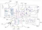
도4는 본 발명의 제3실시예에 따른 정전용량식 수위 감지 회로를 도시하는 회로도이고,
도5는 본 발명의 제4실시예에 따른 정전용량식 수위 감지 회로를 도시하는 회로도이다.
도6은 도4의 전류제한회로의 등가회로를 도시하는 회로도이고,
도7은 도5의 전류제한회로의 등가회로를 도시하는 회로도이다.FIG. 1 is a conceptual view for explaining a conventional capacitive water level sensor,
2 is a circuit diagram showing a capacitance type water level sensing circuit according to the first embodiment of the present invention,
3 is a circuit diagram showing a capacitance type water level sensing circuit according to a second embodiment of the present invention,
4 is a circuit diagram showing a capacitance type water level sensing circuit according to a third embodiment of the present invention,
5 is a circuit diagram showing a capacitance type water level sensing circuit according to a fourth embodiment of the present invention.
Fig. 6 is a circuit diagram showing an equivalent circuit of the current limiting circuit of Fig. 4,
7 is a circuit diagram showing an equivalent circuit of the current limiting circuit of Fig.
이하, 첨부된 도면들을 참조하면서 본 발명의 바람직한 실시예에 대해 상세히 설명하기로 한다. 한편, 해당 기술분야의 통상적인 지식을 가진자로부터 용이하게 알 수 있는 구성과 그에 대한 작용 및 효과에 대한 도시 및 상세한 설명은 간략히 하거나 생략하고 본 발명과 관련된 부분들을 중심으로 상세히 설명하도록 한다.Hereinafter, preferred embodiments of the present invention will be described in detail with reference to the accompanying drawings. Brief Description of Drawings FIG. 1 is a block diagram of a computer system according to an embodiment of the present invention; FIG. 2 is a block diagram of a computer system according to an embodiment of the present invention; FIG.
특히, 본 발명의 실시예에 따른 정전용량식 수위 감지 회로는, 제1전극을 형성하는 센서봉(20)과, 상기 센서봉(20)의 일부분을 이격 수용하여 제2전극을 형성하는 중공관 형태의 가드파이프(40)를 포함하는 정전용량식 수위 감지기에 적용되는 것을 전제로 하며, 이러한 수위 감지 회로는 상기 가드파이프(40)의 내부에 구비되는 회로기판에 집적되어 제1전극 및 제2전극을 통해 정전용량의 변화량을 감지하여 수위를 계측하게 된다.Particularly, the capacitance type water level sensing circuit according to the embodiment of the present invention includes a
상기와 같은 정전용량식 수위 감지기에 적용되는 본 발명의 정전용량식 수위 감지 회로는, 도2 내지 도5를 참조하면 알 수 있듯이, 크게 감지회로부(200)와 지연회로부(400) 및 출력회로부(600)를 포함한다.2 to 5, the capacitance type water level sensing circuit of the present invention applied to the above-described capacitance type water level sensor includes a
먼저, 상기 감지회로부(200)는 일정 크기의 정전용량을 가지는 콘덴서(210)와, 상기 콘덴서(210)의 정전용량과 상기 제1전극 및 제2전극을 통해 측정된 정전용량을 비교하여 하이(High)신호 또는 로우(Low)신호를 출력하는 제1제어유닛(220)을 포함한다. 이러한 제1제어유닛(220)에는 복수의 통신 포트가 형성되어 클록라인(320) 및 데이터라인(340)이 각각 연결된다.The
다음으로, 상기 지연회로부(400)는 상기 클록라인(320) 및 데이터라인(340)을 통해 상기 제1제어유닛(220)과 병렬 연결되며, 상기 제1제어유닛(220)의 출력 신호에 따라 일정 지연시간 후에 하이신호 또는 로우신호를 출력한다. 이러한 지연회로부(400)는 상기 감지회로부(200)와 동기식 직렬 통신(Inter Integrated Circuit) 방식에 의해 연결되는 것이며, 2가닥의 라인, 즉 클록라인(SCL:Serial Clock) 및 데이터라인(SDA:Serial Data)으로 반이중(half-duplex) 통신이 가능하다. 이러한 통신 방식은 멀티 마스터 모드를 지원하기 때문에 N:N으로 다수의 외부 주변회로와 통신이 가능하며, 본 실시예에서와 같이 회로기판의 내부에서 다수의 칩 간 통신에 적합하다. 특히 간단한 회로구성으로 작은 회로기판 내에 소자와 칩을 최대한 간단하게 집적시켜야 하는 본 발명의 특성상 간단한 회로를 구성하는 데에 있어 바람직하다.The
상기와 같은 지연회로부(400)는 연산처리회로, 입출력 인터페이스, 및 메모리가 집적된 싱글칩 마이크로프로세서 형태인 제2제어유닛으로 구성되는데, 상기 메모리에는 상기 제1제어유닛(220)에서 측정된 정전용량 값을 보정하여 측정감도를 조절하는 알고리즘이 프로그램 형태로 저장된다.The
다음으로, 상기 출력회로부(600)는 상기 지연회로부(400)의 출력 신호에 따라 하이신호 또는 로우신호를 외부 출력단자로 전송하고, 회로구동을 위한 직류전압을 공급받는다.Next, the
상기한 출력회로부(600)는, 도2 및 도3에 도시된 바와 같이, 칩 형태의 제3제어유닛(620a,620b)을 포함할 수 있으며, 출력 포트에 따라 PNP 타입과 NPN 타입으로 구별하여 실시될 수 있다.As shown in FIGS. 2 and 3, the
한편, 상기 출력회로부(600)는, 도4에 도시된 바와 같이, 상기 지연회로부(400)의 출력 포트와 연결되어 하이신호 또는 로우신호를 출력하는 NPN 타입의 제1트랜지스터(621)와, 상기 제1트랜지스터(621)의 콜렉터 단자와 연결되어 하이신호 또는 로우신호를 외부 출력단자로 전송하는 PNP 타입의 제2트랜지스터(623)와, 상기 제2트랜지스터(623)의 베이스 단자와 이미터 단자에 각각 연결되어 상기 제2트랜지스터(623)와 함께 전류제한회로(CL1)를 형성하는 PNP 타입의 제3트랜지스터(625) 및 저항(627)을 포함할 수 있다. 여기서, 상기 전류제한회로(CL1)의 등가회로는 도6과 같이 구성될 수 있다. 이러한 전류제한회로는 출력신호에 과부하가 걸렸을 때 회로를 보호하고, 입력 및 출력 신호에 역전압을 가했을 때 회로를 보호하는 역할을 한다.4, the
다르게는, 상기 출력회로부(600)는, 도5에 도시된 바와 같이, 상기 지연회로부(400)의 출력 포트와 연결되어 하이신호 또는 로우신호를 외부 출력단자로 전송하는 NPN 타입의 제1트랜지스터(643)와, 상기 제1트랜지스터(643)의 베이스 단자와 이미터 단자에 각각 연결되어 상기 제1트랜지스터(643)와 함께 전류제한회로(CL2)를 형성하는 NPN 타입의 제2트랜지스터(645) 및 저항(647)을 포함할 수 있다. 여기서, 상기 전류제한회로(CL2)의 등가회로는 도7과 같이 구성될 수 있다.5, the
도4 및 도5의 실시예에서 출력회로부(600)는 별도의 전원회로(660)를 구성하여 회로구동을 위한 직류전압을 공급받으며, 센서봉(20)과 가드파이프(40)에서 감지되는 정전용량에 따라 병렬로 연결되는 콘덴서의 개수 및 회로구성이 가변될 수 있다.4 and 5, the
이하, 상술한 본 발명의 기술 구성을 바탕으로 다양한 실시예에 따른 회로설명을 기술하도록 한다.Hereinafter, a circuit description according to various embodiments will be described based on the technical constitution of the present invention described above.
<제1실시예>≪
도2는 본 발명의 제1실시예에 따른 정전용량식 수위 감지 회로를 도시하는 회로도이다.2 is a circuit diagram showing a capacitive water level sensing circuit according to a first embodiment of the present invention.
센서봉(20)과 가드파이프(40)가 액체 수위 외부에 있으면 제1제어유닛(220)은 로우신호를 동기식 직렬 통신 포트인 SCL 및 SDA 포트를 통해 제2제어유닛(420)으로 전송하게 되고, 제2제어유닛(420)은 출력 포트를 통해 로우신호를 제3제어유닛(620a)으로 전송하고, 제3제어유닛(620a)은 PNP 출력 포트를 통해 로우신호를 출력하여 외부 출력단자(OUTPUT)로 전송한다.When the
이에 따라, 센서봉(20)과 가드파이프(40)가 액체의 수위에 따라 정전용량이 변화하면 제1제어유닛(220)은 콘덴서(210)의 정전용량과 비교하고, 상기 센서봉(20)과 가드파이프(40)에서 측정된 정전용량이 콘덴서(210)의 정전용량보다 작으면 제1제어유닛(220)은 로우신호의 출력을 유지하다가 상기 콘덴서(210)의 정전용량보다 커지면 제1제어유닛(220)은 하이신호를 출력하여 제2제어유닛(420)으로 전송하고, 제2제어유닛(420)은 일정 지연시간 후에 하이신호를 출력하여 제3제어유닛(620a)으로 전송하고, 제3제어유닛(620a)은 하이신호를 출력한다.When the capacitance of the
즉, 센서봉(20)과 가드파이프(40)가 액체에 잠기면 센서봉(20)에서 감지되는 정전용량이 콘덴서(210)의 정전용량보다 커지게 되므로 제2제어유닛(420)은 일정 지연시간 후에 하이신호를 출력하게 되는 것이다.That is, when the
반대로, 센서봉(20)과 가드파이프(40)가 액체에 잠기지 않은 상태가 되면 센서봉(20)에서 감지되는 정전용량이 콘덴서(210)의 정전용량보다 작아지게 되므로 제2제어유닛(420)은 일정 지연시간 후에 로우신호를 출력하게 되는 것이다.Conversely, when the
<제2실시예>≪
도3은 본 발명의 제2실시예에 따른 정전용량식 수위 감지 회로를 도시하는 회로도이다.3 is a circuit diagram showing a capacitance type water level sensing circuit according to a second embodiment of the present invention.
제2실시예는 제3제어유닛(620b)의 출력 포트가 NPN 타입임에 따라, 앞서 설명한 제1실시예와 출력 신호만 반대이고 나머지 구성은 동일 또는 극히 유사하므로 상세한 설명은 생략하기로 한다.In the second embodiment, since the output port of the
<제3실시예>≪ Third Embodiment >
도4는 본 발명의 제3실시예에 따른 정전용량식 수위 감지 회로를 도시하는 회로도이다.4 is a circuit diagram showing a capacitance type water level sensing circuit according to a third embodiment of the present invention.
센서봉(20)과 가드파이프(40)가 액체 수위 외부에 있으면 제1제어유닛(220)은 로우신호를 동기식 직렬 통신 포트인 SCL 및 SDA 포트를 통해 제2제어유닛(420)으로 전송하게 되고, 제2제어유닛(420)의 로우신호는 NPN 타입의 제1트랜지스터(621)의 베이스 단자에 입력되고 상기 제1트랜지스터(621)의 콜렉터 단자는 PNP 타입의 제2트랜지스터(623)의 베이스 단자를 하이 상태로 인가하여 상기 제2트랜지스터(623)의 이미터 단자는 로우신호를 출력하게 된다.When the
센서봉(20)과 가드파이프(40)가 액체의 수위에 따라 정전용량이 변화하면 제1제어유닛(220)은 콘덴서(210)의 정전용량을 비교하고, 상기 센서봉(20)과 가드파이프(40)에서 측정된 정전용량이 콘덴서(210)의 정전용량보다 작으면 제1제어유닛(220)의 로우신호가 NPN 타입의 제1트랜지스터(621)의 베이스 단자에 입력되어 콜렉터 단자의 하이신호 출력이 PNP 타입의 출력용 제2트랜지스터(623)의 베이스를 구동하지 못하여 이미터 단자는 로우 상태로 유지되다가 센서봉(20)과 가드파이프(40)가 액체에 잠기면 센서봉(20)에서 감지된 정전용량이 콘덴서(210)의 정전용량보다 크게 되어 제1제어유닛(220)은 하이신호를 출력하여 제2제어유닛(420)으로 전송하고, 제2제어유닛(420)은 일정 지연시간 후에 하이신호를 출력하여 NPN 타입의 제1트랜지스터(621)의 베이스 단자에 인가하여 콜렉터 단자의 로우신호가 PNP 타입의 출력용 제2트랜지스터(623)의 베이스 단자를 구동하여 이미터 단자는 하이신호를 출력하게 된다.The
즉, 센서봉(20)과 가드파이프(40)가 액체에 잠기면 센서봉(20)에서 감지되는 정전용량이 콘덴서(210)의 정전용량보다 커지게 되므로 제2제어유닛(420)은 일정 지연시간 후에 하이신호를 출력하여 NPN 타입의 제1트랜지스터(621)의 베이스 단자에 인가하고, 이에 따라 PNP 타입의 출력용 제2트랜지스터(623)의 이미터 단자는 하이신호를 출력하게 되는 것이다.That is, when the
반대로, 센서봉(20)과 가드파이프(40)가 액체에 잠기지 않은 상태가 되면 센서봉()에서 감지되는 정전용량이 콘덴서(210)의 정전용량보다 작아지게 되므로 제2제어유닛(420)은 일정 지연시간 후에 로우 신호를 출력하여 NPN 타입의 제1트랜지스터(621)의 베이스 단자에 인가하고, 이에 따라 PNP 타입의 출력용 제2트랜지스터(623)의 이미터 단자는 로우신호를 출력하게 되는 것이다.Conversely, when the
<제4실시예><Fourth Embodiment>
도5는 본 발명의 제4실시예에 따른 정전용량식 수위 감지 회로를 도시하는 회로도이다.5 is a circuit diagram showing a capacitance type water level sensing circuit according to a fourth embodiment of the present invention.
제4실시예는 출력회로(640)의 출력용 제1트랜지스터(643)가 NPN 타입임에 따라, 앞서 설명한 제3실시예와 출력 신호만 반대이고 나머지 구성은 동일 또는 극히 유사하므로 상세한 설명은 생략하기로 한다.Since the
지금까지 설명한 본 발명의 정전용량식 수위 감지 회로에 따르면, 센서봉과 가드파이프로부터 감지되는 정전용량의 변화를 지연시간을 가지고 출력되도록 함으로써 불필요하고 빈번한 감지 동작과 채터링 현상을 방지할 수 있으며, 이에 따라 회로 동작이 안정적이고 수위 감지의 신뢰성이 향상되는 효과가 있다.According to the capacitance type water level detection circuit of the present invention described above, unnecessary and frequent sensing operation and chattering phenomenon can be prevented by outputting a change in the capacitance detected from the sensor rod and the guard pipe with a delay time. The circuit operation is stable and the reliability of the water level detection is improved.
전술한 내용은 후술할 발명의 청구범위를 더욱 잘 이해할 수 있도록 본 발명의 특징과 기술적 장점을 다소 폭넓게 상술하였다. 상술한 실시예들은 해당 기술분야에서 통상의 지식을 가진 자에 의해 본 발명의 기술적 사상의 범위에서 다양한 수정 및 변경이 가능할 것이다. 이러한 다양한 수정 및 변경 또한 본 발명의 기술적 사상의 범위 내라면 하기에서 기술되는 본 발명의 청구범위에 속한다 할 것이다.The foregoing has outlined rather broadly the features and technical advantages of the present invention in order that the claims of the invention to be described below may be better understood. The embodiments described above are susceptible to various modifications and changes within the technical scope of the present invention by those skilled in the art. These various modifications and changes are also within the scope of the technical idea of the present invention and will be included in the claims of the present invention described below.
20: 센서봉(제1전극)40: 가드파이프(제2전극)
200: 감지회로부210: 콘덴서
220: 제1제어유닛320: 클록라인
340: 데이터라인400: 지연회로부
420: 제2제어유닛600: 출력회로부
620,640: 출력회로620a,b: 제3제어유닛
621: 제1트랜지스터(NPN)623: 제2트랜지스터(PNP)
625: 제3트랜지스터(PNP)627: 저항
643: 제1트랜지스터(NPN)645: 제2트랜지스터(NPN)
647: 저항660: 전원회로
CL1: 전류제한회로CL2: 전류제한회로20: sensor rod (first electrode) 40: guard pipe (second electrode)
200: sensing circuit 210: capacitor
220: first control unit 320: clock line
340: Data line 400: Delay circuit part
420: second control unit 600: output circuit part
620, 640:
621: a first transistor (NPN) 623: a second transistor (PNP)
625: third transistor (PNP) 627: resistor
643: a first transistor (NPN) 645: a second transistor (NPN)
647: Resistor 660: Power supply circuit
CL1: Current limit circuit CL2: Current limit circuit
Claims (4)
Translated fromKorean일정 크기의 정전용량을 가지는 콘덴서와, 상기 콘덴서의 정전용량과 상기 제1전극 및 제2전극을 통해 측정된 정전용량을 비교하여 하이(High)신호 또는 로우(Low)신호를 출력하는 제1제어유닛을 포함하며, 복수의 통신 포트에 클록라인 및 데이터라인이 각각 연결되는 감지회로부;
상기 클록라인 및 데이터라인을 통해 상기 제1제어유닛과 병렬 연결되며, 상기 제1제어유닛의 출력 신호에 따라 일정 지연시간 후에 하이신호 또는 로우신호를 출력하는 지연회로부; 및
상기 지연회로부의 출력 신호에 따라 하이신호 또는 로우신호를 외부 출력단자로 전송하고, 회로구동을 위한 직류전압을 공급받는 출력회로부;
를 포함하는 것을 특징으로 하는 정전용량식 수위 감지 회로.The present invention is applicable to a capacitive water level sensor including a sensor bar for forming a first electrode and a hollow pipe-type guard pipe for receiving a part of the sensor rod to form a second electrode. A capacitive water level sensing circuit integrated on a circuit board for sensing a change in capacitance through a first electrode and a second electrode to measure a water level,
A first control unit for comparing a capacitance of the capacitor with a capacitance measured through the first and second electrodes to output a high signal or a low signal, A sensing circuit part including a plurality of communication ports, each of which is connected to a clock line and a data line;
A delay circuit connected in parallel with the first control unit through the clock line and the data line and outputting a high signal or a low signal after a predetermined delay time in accordance with an output signal of the first control unit; And
An output circuit part for transmitting a high signal or a low signal to an external output terminal according to an output signal of the delay circuit part and receiving a DC voltage for driving the circuit;
Wherein the capacitance-type water level sensing circuit comprises:
상기 지연회로부는 연산처리회로, 입출력 인터페이스, 및 메모리가 집적된 싱글칩 마이크로프로세서 형태인 제2제어유닛을 포함하며,
상기 메모리에는 상기 제1제어유닛에서 측정된 정전용량 값을 보정하여 측정감도를 조절하는 알고리즘이 프로그램 형태로 저장되는 것을 특징으로 하는 정전용량식 수위 감지 회로.The method according to claim 1,
Wherein the delay circuit section includes a second control unit in the form of a single chip microprocessor in which an arithmetic processing circuit, an input / output interface, and a memory are integrated,
Wherein the memory stores an algorithm for adjusting the measurement sensitivity by correcting the capacitance value measured by the first control unit in a program form.
상기 출력회로부는,
상기 지연회로부의 출력 포트와 연결되어 하이신호 또는 로우신호를 출력하는 NPN 타입의 제1트랜지스터와,
상기 제1트랜지스터의 콜렉터 단자와 연결되어 하이신호 또는 로우신호를 외부 출력단자로 전송하는 PNP 타입의 제2트랜지스터와,
상기 제2트랜지스터의 베이스 단자와 이미터 단자에 각각 연결되어 상기 제2트랜지스터와 함께 전류제한회로를 형성하는 PNP 타입의 제3트랜지스터 및 저항을 포함하는 것을 특징으로 하는 정전용량식 수위 감지 회로.The method according to claim 1,
The output circuit section includes:
An NPN type first transistor connected to the output port of the delay circuit and outputting a high signal or a low signal,
A second transistor of a PNP type connected to a collector terminal of the first transistor and transmitting a high signal or a low signal to an external output terminal,
A third transistor of a PNP type connected to the base terminal and the emitter terminal of the second transistor and forming a current limiting circuit together with the second transistor; and a resistor.
상기 출력회로부는,
상기 지연회로부의 출력 포트와 연결되어 하이신호 또는 로우신호를 외부 출력단자로 전송하는 NPN 타입의 제1트랜지스터와,
상기 제1트랜지스터의 베이스 단자와 이미터 단자에 각각 연결되어 상기 제1트랜지스터와 함께 전류제한회로를 형성하는 NPN 타입의 제2트랜지스터 및 저항을 포함하는 것을 특징으로 하는 정전용량식 수위 감지 회로.The method according to claim 1,
The output circuit section includes:
A first transistor of an NPN type connected to an output port of the delay circuit section for transmitting a high signal or a low signal to an external output terminal,
And an NPN type second transistor connected to the base terminal and the emitter terminal of the first transistor to form a current limiting circuit together with the first transistor, and a resistor.
Priority Applications (3)
| Application Number | Priority Date | Filing Date | Title |
|---|---|---|---|
| KR1020140033409AKR101414199B1 (en) | 2014-03-21 | 2014-03-21 | Level detecting circuit of Electrostatic capacitance type |
| PCT/KR2015/002833WO2015142144A1 (en) | 2014-03-21 | 2015-03-23 | Capacitive level sensor circuit |
| CN201580014885.3ACN106104225B (en) | 2014-03-21 | 2015-03-23 | Condenser type water level detection circuit |
Applications Claiming Priority (1)
| Application Number | Priority Date | Filing Date | Title |
|---|---|---|---|
| KR1020140033409AKR101414199B1 (en) | 2014-03-21 | 2014-03-21 | Level detecting circuit of Electrostatic capacitance type |
Publications (1)
| Publication Number | Publication Date |
|---|---|
| KR101414199B1true KR101414199B1 (en) | 2014-07-01 |
Family
ID=51740913
Family Applications (1)
| Application Number | Title | Priority Date | Filing Date |
|---|---|---|---|
| KR1020140033409AActiveKR101414199B1 (en) | 2014-03-21 | 2014-03-21 | Level detecting circuit of Electrostatic capacitance type |
Country Status (3)
| Country | Link |
|---|---|
| KR (1) | KR101414199B1 (en) |
| CN (1) | CN106104225B (en) |
| WO (1) | WO2015142144A1 (en) |
Cited By (4)
| Publication number | Priority date | Publication date | Assignee | Title |
|---|---|---|---|---|
| KR20180130334A (en) | 2017-05-29 | 2018-12-07 | (주) 래트론 | Optical water level sensor integrated with case and prism |
| KR102112449B1 (en)* | 2019-06-16 | 2020-05-18 | 주식회사 에프램 | A Capacitive Water Level Sensor |
| WO2021087220A1 (en)* | 2019-10-31 | 2021-05-06 | KSR IP Holdings, LLC | Sensing systems using current steering bridges |
| CN115301388A (en)* | 2022-07-25 | 2022-11-08 | 珠海格力电器股份有限公司 | Garbage disposal device, garbage disposal method and garbage disposal control equipment |
Families Citing this family (2)
| Publication number | Priority date | Publication date | Assignee | Title |
|---|---|---|---|---|
| CN114644314B (en)* | 2017-05-03 | 2024-04-05 | 耐普罗公司 | Apparatus, system and method for providing a liquid level monitor |
| CN115683276A (en)* | 2022-12-07 | 2023-02-03 | 佛山市威烽电器有限公司 | A capacitive liquid level switch |
Citations (3)
| Publication number | Priority date | Publication date | Assignee | Title |
|---|---|---|---|---|
| KR890004951B1 (en)* | 1987-04-11 | 1989-12-02 | 재단법인 한국전자 통신연구소 | Water level detection circuit of electrode |
| KR920008287A (en)* | 1990-10-29 | 1992-05-27 | 김대산 | BIDET attached to the toilet |
| JPH08327434A (en)* | 1995-05-29 | 1996-12-13 | Kuramo Denko Kk | Water level detector |
Family Cites Families (7)
| Publication number | Priority date | Publication date | Assignee | Title |
|---|---|---|---|---|
| JPS59187225A (en)* | 1983-04-06 | 1984-10-24 | Kanbayashi Seisakusho:Kk | Water level informing apparatus for bath tub |
| AU2003270417A1 (en)* | 2002-09-09 | 2004-03-29 | Robertshaw Industrial Products Division | Interface detection using time domain reflectometry with two separate conductive elements |
| US20040149032A1 (en)* | 2003-01-31 | 2004-08-05 | Sell Jeffrey A | Liquid level sensor |
| CN201697690U (en)* | 2009-07-31 | 2011-01-05 | 佛山市中协电器有限公司 | Capacitive sensing liquid level sensor |
| CN202433055U (en)* | 2011-12-20 | 2012-09-12 | 信息产业部电子第四十研究所华成高新技术公司 | Water level sensor |
| CN103023472A (en)* | 2012-12-10 | 2013-04-03 | 烟台荏原空调设备有限公司 | Special liquid level relay for lithium bromide solution |
| CN103256964B (en)* | 2013-04-16 | 2015-12-02 | 周德海 | A kind of capacitance liquid level measurement mechanism |
- 2014
- 2014-03-21KRKR1020140033409Apatent/KR101414199B1/enactiveActive
- 2015
- 2015-03-23WOPCT/KR2015/002833patent/WO2015142144A1/enactiveApplication Filing
- 2015-03-23CNCN201580014885.3Apatent/CN106104225B/enactiveActive
Patent Citations (3)
| Publication number | Priority date | Publication date | Assignee | Title |
|---|---|---|---|---|
| KR890004951B1 (en)* | 1987-04-11 | 1989-12-02 | 재단법인 한국전자 통신연구소 | Water level detection circuit of electrode |
| KR920008287A (en)* | 1990-10-29 | 1992-05-27 | 김대산 | BIDET attached to the toilet |
| JPH08327434A (en)* | 1995-05-29 | 1996-12-13 | Kuramo Denko Kk | Water level detector |
Cited By (5)
| Publication number | Priority date | Publication date | Assignee | Title |
|---|---|---|---|---|
| KR20180130334A (en) | 2017-05-29 | 2018-12-07 | (주) 래트론 | Optical water level sensor integrated with case and prism |
| KR102112449B1 (en)* | 2019-06-16 | 2020-05-18 | 주식회사 에프램 | A Capacitive Water Level Sensor |
| WO2021087220A1 (en)* | 2019-10-31 | 2021-05-06 | KSR IP Holdings, LLC | Sensing systems using current steering bridges |
| CN115301388A (en)* | 2022-07-25 | 2022-11-08 | 珠海格力电器股份有限公司 | Garbage disposal device, garbage disposal method and garbage disposal control equipment |
| CN115301388B (en)* | 2022-07-25 | 2024-02-23 | 珠海格力电器股份有限公司 | Garbage disposal device, garbage disposal method, and garbage disposal control apparatus |
Also Published As
| Publication number | Publication date |
|---|---|
| CN106104225A (en) | 2016-11-09 |
| WO2015142144A1 (en) | 2015-09-24 |
| CN106104225B (en) | 2019-04-09 |
Similar Documents
| Publication | Publication Date | Title |
|---|---|---|
| KR101414199B1 (en) | Level detecting circuit of Electrostatic capacitance type | |
| US9354099B2 (en) | Aircraft fuel level measurement apparatus and method | |
| US20130276533A1 (en) | Device for measuring fluid level in a container | |
| CN103376144B (en) | Liquid level detection device | |
| US20160123787A1 (en) | Measuring Instrument | |
| US11199434B2 (en) | Dual polarity mutual capacitive liquid sensing | |
| CN202548088U (en) | Method for detecting moisture in oil and device for method | |
| WO2018001155A1 (en) | Liquid level sensing device and liquid level detection method | |
| CN105229429B (en) | Liquid level measuring device | |
| KR101414194B1 (en) | Level detecting circuit of Electrostatic capacitance type | |
| US6469525B2 (en) | Method for sensing humidity in a tape library | |
| KR20170104748A (en) | An apparatus for detecting level of the fluid in the tank using a plurality of pcb pad | |
| CN111693111B (en) | Compensation method and compensation circuit of non-contact sensor | |
| CN107957283A (en) | Boiler liquid level measuring system and boiler liquid level measuring method | |
| KR101725157B1 (en) | Conductive-Material detector using electric capacitive sensor | |
| EP3754308B1 (en) | Sensor system | |
| US20220316936A1 (en) | Level measuring device | |
| IT202200022386A1 (en) | METHOD FOR DETECTING THE PRESENCE OF A LIQUID | |
| CA2924724C (en) | Apparatus and method for characterization of fluids or powders by electrical permittivity | |
| CN108332819A (en) | The method of liquid level in liquid storage detection structure, device and detection liquid storage bottle | |
| JPS58106423A (en) | Liquid level measuring device | |
| CN102235899A (en) | Digital liquid level sensor |
Legal Events
| Date | Code | Title | Description |
|---|---|---|---|
| A201 | Request for examination | ||
| PA0109 | Patent application | Patent event code:PA01091R01D Comment text:Patent Application Patent event date:20140321 | |
| PA0201 | Request for examination | ||
| A302 | Request for accelerated examination | ||
| PA0302 | Request for accelerated examination | Patent event date:20140324 Patent event code:PA03022R01D Comment text:Request for Accelerated Examination Patent event date:20140321 Patent event code:PA03021R01I Comment text:Patent Application | |
| E701 | Decision to grant or registration of patent right | ||
| PE0701 | Decision of registration | Patent event code:PE07011S01D Comment text:Decision to Grant Registration Patent event date:20140425 | |
| GRNT | Written decision to grant | ||
| PR0701 | Registration of establishment | Comment text:Registration of Establishment Patent event date:20140625 Patent event code:PR07011E01D | |
| PR1002 | Payment of registration fee | Payment date:20140626 End annual number:3 Start annual number:1 | |
| PG1601 | Publication of registration | ||
| FPAY | Annual fee payment | Payment date:20170621 Year of fee payment:4 | |
| PR1001 | Payment of annual fee | Payment date:20170621 Start annual number:4 End annual number:4 | |
| FPAY | Annual fee payment | Payment date:20180619 Year of fee payment:5 | |
| PR1001 | Payment of annual fee | Payment date:20180619 Start annual number:5 End annual number:5 | |
| FPAY | Annual fee payment | Payment date:20190502 Year of fee payment:6 | |
| PR1001 | Payment of annual fee | Payment date:20190502 Start annual number:6 End annual number:6 | |
| PR1001 | Payment of annual fee | Payment date:20200618 Start annual number:7 End annual number:7 | |
| PR1001 | Payment of annual fee | Payment date:20210311 Start annual number:8 End annual number:8 |