KR101410820B1 - Upper Electrode Assembly and Thin-film Processing Apparatus Having the Same - Google Patents
Upper Electrode Assembly and Thin-film Processing Apparatus Having the SameDownload PDFInfo
- Publication number
- KR101410820B1 KR101410820B1KR1020070141224AKR20070141224AKR101410820B1KR 101410820 B1KR101410820 B1KR 101410820B1KR 1020070141224 AKR1020070141224 AKR 1020070141224AKR 20070141224 AKR20070141224 AKR 20070141224AKR 101410820 B1KR101410820 B1KR 101410820B1
- Authority
- KR
- South Korea
- Prior art keywords
- backing plate
- showerhead
- thin film
- space block
- processing apparatus
- Prior art date
- Legal status (The legal status is an assumption and is not a legal conclusion. Google has not performed a legal analysis and makes no representation as to the accuracy of the status listed.)
- Active
Links
- 239000010409thin filmSubstances0.000titleclaimsabstractdescription42
- 230000002093peripheral effectEffects0.000claimsabstractdescription41
- 230000008878couplingEffects0.000claimsabstractdescription19
- 238000010168coupling processMethods0.000claimsabstractdescription19
- 238000005859coupling reactionMethods0.000claimsabstractdescription19
- 238000000034methodMethods0.000claimsdescription50
- 238000006243chemical reactionMethods0.000claimsdescription14
- 239000011810insulating materialSubstances0.000claimsdescription5
- 239000000126substanceSubstances0.000abstractdescription4
- 239000002245particleSubstances0.000abstractdescription3
- 230000006866deteriorationEffects0.000abstractdescription2
- 239000007789gasSubstances0.000description24
- 239000000758substrateSubstances0.000description12
- 239000012212insulatorSubstances0.000description8
- 238000000623plasma-assisted chemical vapour depositionMethods0.000description8
- 238000000151depositionMethods0.000description6
- 230000008021depositionEffects0.000description5
- 238000005530etchingMethods0.000description5
- 239000000919ceramicSubstances0.000description4
- 239000000470constituentSubstances0.000description4
- 239000000463materialSubstances0.000description4
- 239000012495reaction gasSubstances0.000description4
- 238000000427thin-film depositionMethods0.000description4
- 229910052782aluminiumInorganic materials0.000description3
- XAGFODPZIPBFFR-UHFFFAOYSA-NaluminiumChemical compound[Al]XAGFODPZIPBFFR-UHFFFAOYSA-N0.000description3
- 238000009826distributionMethods0.000description3
- 239000011521glassSubstances0.000description3
- 238000004519manufacturing processMethods0.000description3
- 125000006850spacer groupChemical group0.000description3
- 239000004809TeflonSubstances0.000description2
- 229920006362Teflon®Polymers0.000description2
- 238000005137deposition processMethods0.000description2
- 238000010438heat treatmentMethods0.000description2
- 238000005304joiningMethods0.000description2
- 238000012986modificationMethods0.000description2
- 230000004048modificationEffects0.000description2
- XUIMIQQOPSSXEZ-UHFFFAOYSA-NSiliconChemical compound[Si]XUIMIQQOPSSXEZ-UHFFFAOYSA-N0.000description1
- 230000003213activating effectEffects0.000description1
- 239000010408filmSubstances0.000description1
- 238000009413insulationMethods0.000description1
- 239000004973liquid crystal related substanceSubstances0.000description1
- 229910052751metalInorganic materials0.000description1
- 239000002184metalSubstances0.000description1
- 238000000059patterningMethods0.000description1
- 230000000149penetrating effectEffects0.000description1
- 239000002994raw materialSubstances0.000description1
- 239000000376reactantSubstances0.000description1
- 230000000284resting effectEffects0.000description1
- 238000007789sealingMethods0.000description1
- 239000004065semiconductorSubstances0.000description1
- 229910052710siliconInorganic materials0.000description1
- 239000010703siliconSubstances0.000description1
- 238000005507sprayingMethods0.000description1
Images


Classifications
- C—CHEMISTRY; METALLURGY
- C23—COATING METALLIC MATERIAL; COATING MATERIAL WITH METALLIC MATERIAL; CHEMICAL SURFACE TREATMENT; DIFFUSION TREATMENT OF METALLIC MATERIAL; COATING BY VACUUM EVAPORATION, BY SPUTTERING, BY ION IMPLANTATION OR BY CHEMICAL VAPOUR DEPOSITION, IN GENERAL; INHIBITING CORROSION OF METALLIC MATERIAL OR INCRUSTATION IN GENERAL
- C23C—COATING METALLIC MATERIAL; COATING MATERIAL WITH METALLIC MATERIAL; SURFACE TREATMENT OF METALLIC MATERIAL BY DIFFUSION INTO THE SURFACE, BY CHEMICAL CONVERSION OR SUBSTITUTION; COATING BY VACUUM EVAPORATION, BY SPUTTERING, BY ION IMPLANTATION OR BY CHEMICAL VAPOUR DEPOSITION, IN GENERAL
- C23C16/00—Chemical coating by decomposition of gaseous compounds, without leaving reaction products of surface material in the coating, i.e. chemical vapour deposition [CVD] processes
- C23C16/44—Chemical coating by decomposition of gaseous compounds, without leaving reaction products of surface material in the coating, i.e. chemical vapour deposition [CVD] processes characterised by the method of coating
- C23C16/50—Chemical coating by decomposition of gaseous compounds, without leaving reaction products of surface material in the coating, i.e. chemical vapour deposition [CVD] processes characterised by the method of coating using electric discharges
- C23C16/505—Chemical coating by decomposition of gaseous compounds, without leaving reaction products of surface material in the coating, i.e. chemical vapour deposition [CVD] processes characterised by the method of coating using electric discharges using radio frequency discharges
- C23C16/509—Chemical coating by decomposition of gaseous compounds, without leaving reaction products of surface material in the coating, i.e. chemical vapour deposition [CVD] processes characterised by the method of coating using electric discharges using radio frequency discharges using internal electrodes
- C—CHEMISTRY; METALLURGY
- C23—COATING METALLIC MATERIAL; COATING MATERIAL WITH METALLIC MATERIAL; CHEMICAL SURFACE TREATMENT; DIFFUSION TREATMENT OF METALLIC MATERIAL; COATING BY VACUUM EVAPORATION, BY SPUTTERING, BY ION IMPLANTATION OR BY CHEMICAL VAPOUR DEPOSITION, IN GENERAL; INHIBITING CORROSION OF METALLIC MATERIAL OR INCRUSTATION IN GENERAL
- C23C—COATING METALLIC MATERIAL; COATING MATERIAL WITH METALLIC MATERIAL; SURFACE TREATMENT OF METALLIC MATERIAL BY DIFFUSION INTO THE SURFACE, BY CHEMICAL CONVERSION OR SUBSTITUTION; COATING BY VACUUM EVAPORATION, BY SPUTTERING, BY ION IMPLANTATION OR BY CHEMICAL VAPOUR DEPOSITION, IN GENERAL
- C23C16/00—Chemical coating by decomposition of gaseous compounds, without leaving reaction products of surface material in the coating, i.e. chemical vapour deposition [CVD] processes
- C23C16/44—Chemical coating by decomposition of gaseous compounds, without leaving reaction products of surface material in the coating, i.e. chemical vapour deposition [CVD] processes characterised by the method of coating
- C23C16/455—Chemical coating by decomposition of gaseous compounds, without leaving reaction products of surface material in the coating, i.e. chemical vapour deposition [CVD] processes characterised by the method of coating characterised by the method used for introducing gases into reaction chamber or for modifying gas flows in reaction chamber
- C23C16/45563—Gas nozzles
- C23C16/45565—Shower nozzles
- C—CHEMISTRY; METALLURGY
- C23—COATING METALLIC MATERIAL; COATING MATERIAL WITH METALLIC MATERIAL; CHEMICAL SURFACE TREATMENT; DIFFUSION TREATMENT OF METALLIC MATERIAL; COATING BY VACUUM EVAPORATION, BY SPUTTERING, BY ION IMPLANTATION OR BY CHEMICAL VAPOUR DEPOSITION, IN GENERAL; INHIBITING CORROSION OF METALLIC MATERIAL OR INCRUSTATION IN GENERAL
- C23C—COATING METALLIC MATERIAL; COATING MATERIAL WITH METALLIC MATERIAL; SURFACE TREATMENT OF METALLIC MATERIAL BY DIFFUSION INTO THE SURFACE, BY CHEMICAL CONVERSION OR SUBSTITUTION; COATING BY VACUUM EVAPORATION, BY SPUTTERING, BY ION IMPLANTATION OR BY CHEMICAL VAPOUR DEPOSITION, IN GENERAL
- C23C16/00—Chemical coating by decomposition of gaseous compounds, without leaving reaction products of surface material in the coating, i.e. chemical vapour deposition [CVD] processes
- C23C16/44—Chemical coating by decomposition of gaseous compounds, without leaving reaction products of surface material in the coating, i.e. chemical vapour deposition [CVD] processes characterised by the method of coating
- C23C16/458—Chemical coating by decomposition of gaseous compounds, without leaving reaction products of surface material in the coating, i.e. chemical vapour deposition [CVD] processes characterised by the method of coating characterised by the method used for supporting substrates in the reaction chamber
- C23C16/4582—Rigid and flat substrates, e.g. plates or discs
- C23C16/4583—Rigid and flat substrates, e.g. plates or discs the substrate being supported substantially horizontally
- C23C16/4586—Elements in the interior of the support, e.g. electrodes, heating or cooling devices
Landscapes
- Chemical & Material Sciences (AREA)
- Engineering & Computer Science (AREA)
- General Chemical & Material Sciences (AREA)
- Chemical Kinetics & Catalysis (AREA)
- Materials Engineering (AREA)
- Mechanical Engineering (AREA)
- Metallurgy (AREA)
- Organic Chemistry (AREA)
- Physics & Mathematics (AREA)
- Plasma & Fusion (AREA)
- Chemical Vapour Deposition (AREA)
Abstract
Translated fromKoreanDescription
Translated fromKorean본 발명은 박막 처리 장치에 관한 것으로, 보다 상세하게는 상부 전극으로 기능하는 백킹 플레이트와 샤워헤드를 연결하는 조립체 및 이러한 조립체를 포함한 박막 처리 장치에 관한 것이다.BACKGROUND OF THE
반도체 소자 또는 태양전지, 액정표시장치와 같은 태양전지소자를 제조하기 위해서는 그 원료가 되는 실리콘 웨이퍼 또는 글라스 등과 같은 기판으로 다양한 공정이 수행된다. 일례로 기판 표면에 패턴을 형성하기 위해서 금속 소스로부터 박막을 형성하는 증착 공정, 얻어진 박막의 일부를 노출시키는 패터닝 공정, 박막의 노출된 부분을 제거하는 식각 공정 등이 수행된다.In order to manufacture a solar cell device such as a semiconductor device, a solar cell, or a liquid crystal display device, various processes are performed on a substrate such as a silicon wafer or glass as a raw material thereof. For example, a deposition process for forming a thin film from a metal source to form a pattern on a substrate surface, a patterning process for exposing a part of the obtained thin film, an etching process for removing an exposed portion of the thin film, and the like are performed.
이러한 박막 증착 및 식각과 같은 박막 처리 공정은 통상 고진공으로 외부와 밀폐된 반응 영역이 정의되어 있는 챔버와 같은 박막처리장치에서 진행된다. 그런데, 공정챔버의 상부에서 소스 물질 및/또는 반응 물질이 가스 형태로 유입되어 증 착 또는 식각 공정을 진행하는 경우, 반응 가스와 소스 가스가 기판의 상면으로 균일하게 분포할 수 있도록 다수의 관통홀이 형성되는 샤워헤드 어셈블리가 이용되고 있다. 특히, 최근에는 RF(radio frequency)에 의하여 얻어진 고전압의 에너지를 이용하여 공정 챔버 내부로 공급된 소스 및 반응 가스를 플라즈마 상태로 여기시킨 상태에서 소스 및 반응 가스 사이의 화학 반응을 유도하여 박막 증착 등을 수행하는 플라즈마-강화 화학기상증착 (Plasma Enhanced Chemical Vapor Deposition, PECVD) 방법이 폭넓게 사용되고 있다.Thin film processing such as thin film deposition and etching typically proceeds in a thin film processing apparatus, such as a chamber, in which a high vacuum is used to define a sealed reaction zone from the outside. When the source material and / or the reactant are introduced in the form of gas at the upper part of the process chamber and the deposition or etching process is performed, the reaction gas and the source gas are uniformly distributed on the upper surface of the substrate. A showerhead assembly is used. In particular, in recent years, a chemical reaction between a source and a reaction gas is induced in a state where a source and a reaction gas supplied into a process chamber are excited into a plasma state by using a high voltage energy obtained by RF (radio frequency) A plasma enhanced chemical vapor deposition (PECVD) method is widely used.
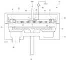
도 1은 종래 평판표시소자의 제조를 위한 PECVD 방식의 챔버형 박막처리장치를 개략적으로 도시한 단면도이고, 도 2는 도 1의 박막처리장치 내부의 상단 주변부의 일 부분을 확대하여 표시한 도면이다. 도시한 바와 같이, 종래 PECVD 방식의 박막처리장치는 외부 영역과 차단되는 고진공의 반응 영역이 형성되는 공정 챔버(10)를 포함하고 있다. 공정 챔버(10) 내부에서의 박막 처리를 위하여, 웨이퍼 또는 글라스와 같은 기판(S)이 인입된 공정 챔버(10)의 반응 영역으로 소정의 소스 또는 반응 가스를 유입시킨 뒤 이를 활성화시켜 박막 증착 등의 공정이 진행된다.FIG. 1 is a cross-sectional view schematically showing a PECVD type chamber-type thin film processing apparatus for manufacturing a conventional flat panel display device, and FIG. 2 is an enlarged view of a portion of a top peripheral portion inside the thin film processing apparatus of FIG. 1 . As shown in the figure, the conventional PECVD type thin film processing apparatus includes a
구체적으로 살펴보면, 공정 챔버(10)의 상단은 리드(20)에 의하여 외부와 격리되어 있는데 리드(20)의 내측으로는 그 내부를 횡단하는 샤워헤드(showerhead, 30)와, 샤워헤드(30) 상부의 디퓨저 커버(diffuser cover)라고도 불리는 백킹 플레이트(backing plate, 34)가 형성된다. 공정가스는 가스라인(미도시)을 경유하여 상단 리드(22)의 중앙 및 백킹 플레이트(34)의 중앙을 관통하는 가스 유입관(60)에 의하여 백킹 플레이트(34)의 저면으로 주입되며, 주입된 공정가스는 백킹 플레이트(34) 및 샤워헤드(30) 사이에 형성된 배플(baffle, 36)에 의하여 1차로 확산된 뒤, 샤워헤드(30)에 다수 형성된 가스 분배홀(32)을 통하여 반응 영역으로 분산된다. 이와 같이 분사되는 공정가스를 활성화하는데 필요한 에너지를 공급하기 위해서 RF 전원(62)이 백킹 플레이트(34) 및/또는 샤워헤드(30)와 연결되는바, 백킹 플레이트(34) 및 샤워헤드(30)는 상부 전극으로서 기능한다.Specifically, the upper end of the
또한, 샤워헤드(30)와 반응 영역을 두고 대향적으로 이격되는 공정 챔버(10)의 하단 내부에는 기판(S)이 안착되는 척의 역할과 함께 바이어스 전압이 인가되는 하부전극(70)이 상하 승강이 가능하도록 구성되어 있다. 하부전극(70)의 내부에는 히터(72)가 매설되어, 박막의 증착 과정에서 그 상부로 안착된 기판(S)을 증착에 적합한 온도로 상승시킨다. 아울러, 기판(S)에 증착되는 공정물질이 가장자리로 증착되는 것을 방지하도록 하부전극(70)의 측면 상부에는 에지 프레임(74)이 설치되어 기판(S)의 가장자리를 덮고 있으며, 증착 공정 후 챔버(10) 내부에 잔류하는 공정가스를 외부로 배출시키도록 배기포트(52)가 마련되어 외부의 흡기시스템(미도시)을 통해서 챔버 내부의 반응 영역을 배기할 수 있도록 구성된다.In addition, a lower electrode 70, to which a bias voltage is applied, and a lower electrode 70 to which a bias voltage is applied act as a chuck on which the substrate S is seated in the lower end of the
특히, 도 2에 도시된 것과 같이, 공정가스를 기판(S)의 상면으로 분사시킴과 동시에 상부전극으로 기능하는 샤워헤드(30)와 백킹 플레이트(34)는 가장자리에서 다수의 볼트(42)를 통해 접촉되어 전기적으로 연결되며, 상기 샤워헤드(30) 및 백킹 플레이트(34)가 체결되는 주변부와 측면 리드(20) 사이는 전기적 절연 및 공정 챔버 내부의 진공상태를 유지할 수 있도록 다수의 절연부재(44, 46, 48)가 개재되어 있다. 즉, 샤워헤드 주변부(31)의 외주변과 백킹 플레이트(34)의 주변부 하단으로는 제 1 절연체(44)가 개재되고, 제 1 절연체(44)의 내주변과 샤워헤드 말단부(31b)의 외주변 사이에는 클램핑(52)를 통하여 샤워헤드의 수직 절곡부(31a)로부터 바깥을 향하여 연장되는 샤워헤드 말단(31b) 및 백킹 플레이트 주변부 저면(35b)를 관통하는 볼트(55)가 체결되는 체결부(50)가 구비되어 있고, 제 1 절연체(44) 및 체결부(50)는 리드(20)와 연결되는 제 2 절연체(46)에 의하여 지지된다. 아울러, 백킹 플레이트 말단(35a)과 리드(20) 사이로는 제 3 절연체(48)가 개재되어 있다.2, the
그런데, 종래 샤워헤드 주변부(31)는 그 내측 영역에 비하여 상향 연장되는 수직 절곡부(31a)와 아주 가는 형태를 가지면서 이 수직 절곡부(31a)로부터 외측을 향하여 연장하는 말단부(31b)로 구성되는데, 이 말단부(31b)는 백킹 플레이트 체결단(35b)로까지 연장되어 있어, 샤워헤드 주변부(31)는 다른 영역에 비하여 훨씬 얇은 바 형태를 취하고 있다. 이와 같이 샤워헤드 주변부(31)를 얇게 구성한 것은 샤워헤드(30)로 전달되는 열에 의하여 샤워헤드가 열 팽창되는 정도를 감소하기 위한 것이다.Conventionally, the shower head
즉, 공정 챔버(10)와 같은 박막처리장치에서 공정가스를 열분해하여 기판(S)의 상면으로 박막을 증착하기 위해서는 하부전극(70)의 내부에 매설된 히터(72)와 같은 발열 수단의 작용에 의하여 하부전극(70)의 온도는 대략 300~400℃로 유지되 기 때문에 하부전극(70)과 반응영역을 매개로 이격되어 있는 샤워헤드(30)의 온도가 큰 폭으로 상승한다. 샤워헤드(30)는 통상 알루미늄 재질로 제조되므로, 하부전극(70)으로부터 복사된 열을 전달받은 샤워헤드(30)는 열팽창하게 되는데, 최근 기판의 크기가 대형화/대면적화되고 있는 추세에 맞추어 기판 크기에 비례하여 설치되는 샤워헤드 역시 온도 상승에 따라 그 주변부(31)로 팽창하는 길이가 증가하게 된다. 샤워헤드 주변부(31)를 확고하게 고정시켜 열팽창을 억제한다면 샤워헤드 자체가 뒤틀리는 것과 같은 변형이 야기될 수 있기 때문에, 샤워헤드 주변부를 다른 영역과 비교하여 훨씬 얇은 형태를 가지도록 함으로써, 열팽창에 의한 변형을 억제하고자 하는 것이다.That is, in order to deposit the thin film on the upper surface of the substrate S by thermally decomposing the process gas in the thin film processing apparatus such as the
그럼에도 불구하고, 특히 가느다란 형태로 외측을 향하여 연장되어 있는 샤워헤드 말단부(131b)는 그 외측 방향으로 향하여 열팽창하게 된다. 샤워헤드 말단부(131b)의 열팽창에 따라 백킹 플레이트 체결부(35b) 및/또는 클램핑 바(52)를 통하여 샤워헤드 말단부(131b) 및 백킹 플레이트(35)의 주변부 저면을 관통하는 볼트(54) 등의 체결 수단과의 열 팽창 마찰로 인한 마이크로 아킹(Micro arcing)이 발생한다. 이러한 샤워헤드 말단부(131b)와 주변 부품과의 마이크로 아킹에 의하여 파티클과 같은 이물질은 샤워헤드(30)와 백킹 플레이트(34) 사이의 버퍼 영역으로 이동하고, 샤워헤드(30)에 다수 형성된 가스분배홀(32)을 통하여 박막 증착 등이 이루어지는 기판(S)의 상면으로 떨어진다. 이에 따라 제작된 박막에는 이물질이 포함되기 때문에 박막의 품질 저하를 야기하게 된다.Nevertheless, the showerhead end portion 131b, which is particularly elongated toward the outside in a thin shape, is thermally expanded toward the outward direction. A
본 발명의 일 목적은 샤워헤드 주변부 말단의 측면 방향으로의 열팽창에 의하여 샤워헤드 주변부와 백킹 플레이트 사이에서의 마이크로 아킹에 따른 이물질의 발생을 억제할 수 있는 박막처리장치의 상부 전극을 연결하는 조립체 및 이를 포함하고 있는 박막처리장치를 제공하고자 하는 것이다.An object of the present invention is to provide an assembly for connecting an upper electrode of a thin film processing apparatus capable of suppressing the generation of foreign matter due to micro arcing between a periphery of a showerhead and a backing plate due to thermal expansion in a lateral direction of a periphery of a showerhead, And a thin film processing apparatus including the same.
본 발명의 다른 목적은 공정 영역으로 방출되는 파티클과 같은 이물질의 발생을 억제함으로써 형성된 박막의 품질을 향상시킬 수 있는 상부 전극 조립체 및 이를 포함하는 박막처리장치를 제공하는데 있다.It is another object of the present invention to provide an upper electrode assembly capable of improving the quality of a thin film formed by suppressing the generation of foreign matter such as particles emitted to a process region, and a thin film processing apparatus including the same.
본 발명의 다른 목적 및 이점은 후술하는 발명의 상세한 설명 및 첨부하는 도면을 통해서 더욱 분명해질 것이다.Other objects and advantages of the present invention will become more apparent from the following detailed description of the present invention when taken in conjunction with the accompanying drawings.
상기와 같은 목적을 갖는 본 발명의 일 관점에 따르면, 박막처리장치의 상부 전극을 이루는 백킹 플레이트 및 샤워헤드를 연결하는 조립체로서, 상기 샤워헤드의 외주변 및 상기 백킹 플레이트 주변부의 저면 사이에 개재되는 스페이스 블록과; 상기 스페이스 블록의 상면과 상기 백킹 플레이트의 저면을 결합하는 제 1 결합부재와; 상기 스페이스 블록의 내주면과 상기 샤워헤드의 수직 연장된 말단을 결합하는 제 2 결합부재를 포함하는 조립체를 제공한다.According to an aspect of the present invention, there is provided an assembly for connecting a backing plate and a showerhead, which are upper electrodes of a thin film processing apparatus, and which is interposed between an outer periphery of the showerhead and a bottom surface of the periphery of the backing plate A space block; A first engaging member for engaging an upper surface of the space block with a bottom surface of the backing plate; And a second engagement member coupling the inner peripheral surface of the space block and the vertically extended end of the showerhead.
이때, 상기 제 2 결합부재가 결합되는 상기 스페이스 블록의 내측 하단은 상기 샤워헤드의 외주변을 향하여 연장될 수 있는바, 상기 제 2 결합부재는 상기 샤워헤드의 외주변을 향하여 연장되어 있는 상기 스페이스 블록의 하단 상면에 배치되어 있는 것을 특징으로 한다.At this time, the inner lower end of the space block to which the second engagement member is coupled may extend toward the outer periphery of the showerhead, and the second engagement member may extend toward the outer periphery of the showerhead, And is disposed on the upper surface of the lower end of the block.
본 발명의 일 실시예에 따르면, 상기 제 1 결합 부재 및 상기 제 2 결합 부재는 상기 백킹 플레이트의 주변부 저면과 상기 샤워헤드 주변부 상면에 걸쳐 절곡된 단면을 가지면서 배치되는 조인트 블록을 통하여 각각 백킹 플레이 주변부 저면 및 상기 샤워헤드의 수직 연장된 말단에 결합되어 있다.According to an embodiment of the present invention, the first engaging member and the second engaging member are connected to each other through a joint block arranged with a bent cross section over a bottom peripheral surface of the backing plate and an upper surface of the shower head peripheral portion, A peripheral bottom and a vertically extended end of the showerhead.
본 발명에 따라 상부전극 조립체를 이루는 상기 스페이스 블록은 절연 재질로 형성되며, 상기 제 1 결합부재는 상기 스페이스 블록의 상면에 배치되는 제 1 클램핑 바에 의하여 백킹 플레이트 주변부에 결합되는 제 1 체결수단을 포함하고, 상기 제 2 결합 부재는 상기 스페이스 블록의 내주면에 밀착 배치되는 제 2 클램핑 바에 의하여 샤워헤드의 수직 연장된 말단을 결합되는 제 2 체결수단을 포함할 수 있다.According to the present invention, the space block constituting the upper electrode assembly is formed of an insulating material, and the first engaging member includes first fastening means coupled to the periphery of the backing plate by a first clamping bar disposed on the upper surface of the space block And the second engagement member may include second fastening means coupled to a vertically extended end of the showerhead by a second clamping bar closely disposed on an inner circumferential surface of the space block.
본 발명의 다른 관점에 따르면, 반응 영역이 정의되어 있으며, 내부로 인입된 피처리물을 처리하는 박막 처리 장치로서, 상기 피처리물을 안착하며 접지되어 있는 하부 전극과; 상술한 조립체에 의하여 연결되는 샤워헤드 및 백킹 플레이트를 포함하며, 상기 하부 전극과 이격되어 있는 상부 전극을 포함하는 박막 처리 장치를 제공한다.According to another aspect of the present invention, there is provided a thin film processing apparatus having a reaction region defined therein, the thin film processing apparatus comprising: a lower electrode which is grounded to receive the object to be processed; A thin film processing apparatus including a showerhead and a backing plate connected by the above-described assembly, and an upper electrode spaced apart from the lower electrode.
본 발명에 따른 상기 박막 처리 장치는 플라즈마 강화 화학 기상 증착 장치 인 것을 특징으로 한다.The thin film processing apparatus according to the present invention is characterized by being a plasma enhanced chemical vapor deposition apparatus.
본 발명에서는 샤워헤드 주변부의 길이 방향으로 연장되는 말단을 제거하는 대신에 백킹 플레이트와 샤워헤드를 연결하기 위한 결합부를 각각 별도로 구성함으로써, 하부전극으로부터의 열전도에 따라 샤워헤드가 외측 방향을 향하여 열팽창함으로써 야기되는 마이크로 아킹을 미연에 방지할 수 있게 되었다.According to the present invention, the connecting portions for connecting the backing plate and the showerhead are separately formed instead of removing the end portions extending in the longitudinal direction of the showerhead peripheral portion, so that the showerhead thermally expands in accordance with the heat conduction from the lower electrode It is possible to prevent micro-arcing caused by this phenomenon.
따라서 샤워헤드와 백킹 플레이트 사이의 마이크로 아킹에 따른 이물질이 발생하지 않기 때문에 종래 이와 같이 발생된 이물질이 샤워헤드 하부에 배치된 피처리물의 상부로 떨어짐에 따른 박막의 품질 저하는 물론이고, 이물질의 발생으로 인한 장비의 불량화를 억제하여, 장비의 신뢰성을 확보할 수 있다.Accordingly, since no foreign matter due to the micro arcing between the showerhead and the backing plate is generated, the quality of the thin film deteriorates as a result of the foreign substances generated in the conventional manner falling to the upper portion of the target object disposed under the shower head, And the reliability of the equipment can be secured.
본 발명에서는 피처리물로의 공정가스 증착을 위하여 하부 전극 내부에 매설되는 히터 등의 발열 수단에 의하여 반응 영역을 사이에 두고 하부 전극과 대향적인 위치에 배치되는 샤워헤드가 고온의 열에 의하여 외측을 향하여 연장됨에 따라 백킹 플레이트 및 결합 부재 등과 마찰이 일어나고, 이로 인하여 파티클 등의 이물질이 생성되어 기판의 상면으로 떨어짐에 따라 소자의 품질 저하와 같은 문제점을 해결하기 위해서 상부전극 주변부의 결합 구조를 변경하였는바, 첨부하는 도면을 참조하여 본 발명을 보다 상세하게 설명한다.In the present invention, a showerhead disposed at a position opposite to the lower electrode with a reaction region sandwiched by a heating means such as a heater buried in the lower electrode for deposition of a process gas into an object to be processed, The bonding structure of the peripheral portion of the upper electrode is changed in order to solve the problems such as the deterioration of the quality of the device due to the friction with the backing plate and the coupling member and the like, The present invention will be described in more detail with reference to the accompanying drawings.
도 3은 본 발명에 따른 결합체가 구비되어 평판표시소자의 제조를 위한 박막처리장치의 일 예로서 플라즈마가 강화 화학기상증착 장치를 개략적으로 도시한 단면도이고, 도 4는 도 3의 B부분을 확대한 단면도로서, 박막처리장치의 상부 전극을 이루는 샤워헤드와 백킹 플레이트의 주변부를 연결하는 조립체를 이루는 구성 부재의 배치 및 결합 관계를 구체적으로 나타내고 있다.FIG. 3 is a cross-sectional view schematically showing a plasma enhanced chemical vapor deposition apparatus as an example of a thin film processing apparatus for manufacturing a flat panel display device having a combination body according to the present invention, FIG. 4 is a cross- And shows the arrangement and coupling relationship of the constituent members constituting the assembly connecting the showerhead constituting the upper electrode of the thin film processing apparatus and the peripheral portion of the backing plate.
도 3에 도시된 것과 같이, 본 발명에 따른 박막처리장치는 외부 영역과 차단되어 진공상태의 반응 영역이 정의되어 있어, 박막 증착과 같은 실질적인 공정이 수행되는 공정 챔버(110)를 포함하고 있다. 공정 챔버(110)는 하부의 반응 영역이 정의되어 있는 챔버 바디(112)와, 상부의 리드(120)로 구분될 수 있는데, 그 사이에는 공정 챔버(110)의 측벽 중앙에 개재된 오-링과 같은 실링 부재가 개재되어 있어, 공정 챔버(110)의 내부를 외부 영역으로부터 밀폐시키고 있다. 공정 챔버(110) 내부에서의 박막 처리 등의 공정을 수행하기 위하여, 웨이퍼 또는 글라스와 같은 피처리물(S)이 공정 챔버(110)의 내부로 인입되면, 반응 영역으로 필요에 따른 소스 가스 또는 반응 가스와 같은 공정 가스가 유입되는데, 유입된 공정 가스를 활성화시킴으로써 박막 증착, 식각 등의 공정이 진행된다.As shown in FIG. 3, the thin film processing apparatus according to the present invention includes a
구체적으로 공정 챔버(110) 상단 내부는 공정 챔버(110)의 상단 외곽을 이루는 리드(120)에 의하여 외부와 격리되어 있는데, 리드(120)의 내측으로는 그 내부를 횡단하는 샤워헤드(130)와, 샤워헤드(130)의 주변부를 제외하고는 샤워헤 드(130)의 상면과 이격되어 있는 백킹 플레이트(134)가 설치된다. 각각의 공정에서 요구되는 공정 가스는 도시하지 않은 가스라인을 경유하여 상단 리드(122) 및 백킹 플레이트(134)의 중앙을 관통하는 가스 유입관(160)에 의하여 백킹 플레이트(134)의 하부로 주입되는데, 주입된 공정가스는 백킹 플레이트(134) 및 샤워헤드(130) 사이의 중앙 버퍼 영역에 형성된 배플(136)에 의하여 1차로 확산된 뒤, 샤워헤드(130)에 다수 형성된 가스분배홀(132)을 통하여 샤워헤드(130) 하부의 반응 영역으로 확산된다. 이와 같이 분사되는 공정가스를 활성화하는데 필요한 에너지를 공급하기 위해서 RF 전원(162)이 백킹 플레이트(134) 및/또는 샤워헤드(130)와 연결되어 샤워헤드(130)를 통해 분사된 공정가스를 플라즈마 형태로 변환함으로써 박막 증착 또는 식각 등이 가능하다. 이러한 의미에서 백킹 플레이트(134) 및 샤워헤드(130)는 상부 전극으로서 기능한다.The inside of the upper end of the
한편, 공정 챔버(110)의 하부를 구성하는 챔버 바디(112)의 내부에는 샤워헤드(130)의 저면과 반응 영역을 두고 대향적으로 이격되어 있는 하부전극(170)이 형성된다. 하부전극(170)은 공정 챔버(110) 내부로 인입되는 피처리물(S)을 그 상부에 안착하는 척의 역할과 함께 바이어스 전압이 인가되는데, 상하 승강이 가능하도록 구성되어 있다. 하부 전극(170)의 내부는 예를 들어 피처리물(S)의 상면으로 공정가스를 증착하는 과정에서 피처리물(S)의 온도를 증착에 적합한 온도로 상승시킬 수 있도록 히터(172)와 같은 발열 수단이 매설되며 전기적으로 접지되어 있어 하부전극으로 기능할 수 있다. 아울러, 피처리물(S)에 증착되는 공정물질이 가장자리로 증착되는 것을 방지하도록 하부전극(170)의 측면 상부에는 에지 프레임(174)이 설치되어 피처리물(S)의 가장자리를 덮고 있으며, 증착 공정 후 공정 챔버(110) 내부에 잔류하는 공정가스를 외부로 배출시키도록 배기포트(152)가 마련되어 외부의 흡기시스템(미도시)을 통해서 챔버 내부의 반응 영역을 배기할 수 있도록 구성된다.A
특히, 본 발명의 일 실시예에서는 상부 전극을 이루는 샤워헤드(130)와 백킹 플레이트(134)의 주변부를 결합하는 구조 및 배치가 종래와 비교할 때 큰 차이를 보이고 있다. 즉, 도 4에 도시된 것과 같이 본 발명에 따르면 박막처리장치의 상부 전극으로 기능하는 샤워헤드(130)와 백킹 플레이트(134)를 주변부에서 결합, 연결할 수 있도록 샤워헤드(130)의 외주변으로 별도의 스페이스 블록(210)이 형성되어 있으며, 스페이스 블록(210)을 통하여 각각 제 1 결합부재(220) 및 제 2 결합부재(230)가 형성되어 각각 백킹 플레이트(134) 및 샤워헤드(130)의 주변을 결합함으로써, 샤워헤드(130)와 백킹 플레이트(134)가 전기적으로 연결될 수 있도록 구성되어 있다.Particularly, in the embodiment of the present invention, the structure and arrangement for coupling the
한편, 샤워헤드(130) 및 백킹 플레이트(134)가 체결되는 상부 전극의 주변부와 측면 리드(20) 사이는 전기적 절연 및 공정챔버 내부의 진공상태를 유지할 수 있도록 다수의 절연부재(44, 46, 48)가 개재되어 있다. 예컨대, 측면 리드(120)와 상부 전극 사이의 영역으로 플라즈마가 형성되는 것을 방지하기 위하여 세라믹 절연체(144)가 백킹 플레이트 주변부(135b) 하단 및 샤워헤드(130) 외주변에 밀착, 개재되는 스페이스 블록(210)의 외측에 형성되어 상부 전극과 측면 리드(120) 사이 의 절연 역할을 수행하고 있으며, 세라믹 절연체(144) 및 스페이스 블록(210)의 저면을 따라 세라믹 확장부(146)가 측면 리드(120)의 저면 일부를 관통하도록 설치된다. 아울러, 백킹 플레이트(134)로부터 측면 리드(120)를 전기적으로 절연시키기 위하여 백킹 플레이트 말단(135a)과 측면 리드 사이에 O-링을 매개로 테프론 절연체(148)가 위치하고 있다.A plurality of
특히, 샤워헤드(130) 외주변 및 백킹 플레이트 주변부(135b) 사이에 개재되는 절연 재질의 스페이스 블록(210)을 매개로 그 상부와 내주면으로 각각 백킹 플레이트 주변부(135b)의 저면 및 샤워헤드 말단(131)과 체결되는 별도의 결합부재(220, 230)가 형성되는데, 본 실시예에서는 각각 독립적으로 설치되는 결합부재(220, 230)의 체결을 위하여 샤워헤드(130) 및 백킹 플레이트(134)의 주변부 사이의 버퍼 영역으로 일정한 단면을 갖는 조인트 블록(240)이 형성되어 있다. 즉, 본 실시예에 따르면 백킹 플레이트 주변부(135b)의 저면을 따라 내측으로 연장된 뒤, 샤워헤드(130) 주변부에 다른 영역과 비교하여 연직 방향으로 상향 연장되어 있는 는 바-형상의 샤워헤드 말단(131)의 내주변을 따라 수직 절곡되는 형상의 조인트 블록(240)이 소정의 두께를 가지면서 형성되어 있다. 바람직하게는 샤워헤드(130)와 동일한 알루미늄 재질의 조인트 블록(240)은 샤워헤드(130) 및 백킹 플레이트(134) 주변부의 버퍼 공간 사이에 배치되어 있고, 본 실시예에서는 이 조인트 블록(240)을 매개로 하여 결합부재(220, 230)가 체결되어 백킹 플레이트 주변부 및 샤워헤드의 수직 연장된 말단에 결합된다.Particularly, through the
구체적으로 살펴보면, 수직 연장된 바-형상의 샤워헤드 말단(131)의 외주변에 인접하여 그 저면이 세라믹 연장부(146)에 의하여 지지되는 테프론과 같은 절연 재질의 스페이스 블록(210)이 개재되는데, 스페이서 블록(210)의 상부와, 백킹 플레이트 주변부(135b) 저면에 밀착되어 있는 조인트 블록(140)의 수평부(242) 사이로 제 1 클램핑 바(224)가 형성되어 있다. 이와 같이 스페이스 블록(210)의 상면에 밀착, 형성된 제 1 클램핑 바(224)를 통하여 볼트와 같은 제 1 체결수단(222)이 조인트 블록의 수평부(242)를 관통하여 백킹 플레이트 주변부(135b)의 저면으로 결합되어 있다.Specifically, a
한편, 종래 샤워헤드의 열팽창으로 인한 문제점을 해결할 수 있도록 본 발명의 샤워헤드 주변부의 형태는 종래와 달리 외측을 향하여 수평 연장되는 부분을 없애고 단지 수직 연장되는 말단(131)만으로 형성되어 있는바, 샤워헤드(130)를 백킹 플레이트(134)와 결합할 수 있도록 이 수직 연장된 샤워헤드 말단(131)을 관통하는 제 2 결합부재(230)가 제 1 결합부재(220)와 비교할 때 사실상 직교하는 방향으로 배치되어 있다.In order to solve the problem caused by the thermal expansion of the showerhead, the shape of the periphery of the showerhead of the present invention is formed only by the
즉, 스페이스 블록(210)의 내주면과 샤워헤드의 수직 연장된 말단(131) 외주변 사이로 제 2 클램핑 바(234)를 밀착시키고, 제 2 클램핑 바(234)를 통하여 제 2 체결수단(232)이 샤워헤드 말단(131)을 관통하여 알루미늄 재질의 조인트 블록의 수직부(244)로 결합될 수 있도록 구성된다. 특히, 제 2 결합부재(230)의 배치를 위해서 스페이스 블록(210)의 내측 하단(212)는 내측 상단(214)에 비하여 샤워헤 드(130)의 외주변을 향하여 연장되는 단면을 가지도록 하여, 제 2 결합부재(230)를 이루는 제 2 클램핑 바(244) 및/또는 제 2 클램핑 바(244)에 의하여 샤워헤드 말단(131)을 관통하는 제 2 체결수단(242)의 일부가 스페이서 블록(210)의 내측 하단(212) 상면으로 안착될 수 있도록 배치되어 있다.The
즉, 본 실시예에 따르면 샤워헤드의 수직 연장된 말단(131)의 외주변을 따라 배치되는 절연 재질의 스페이스 블록(210)은 전체적으로는 상단과 하단의 단면이 동일한 바-형상을 가지지만, 샤워헤드의 수직 연장된 말단(131)을 결합하기 위하여 제 2 결합부재(230)가 배치되는 영역에서는 그 하단이 샤워헤드(130) 외주변을 향하여 연장되는 형상을 취하고 있다.That is, according to the present embodiment, the
이와 같이, 종래 샤워헤드 말단이 수평 길이 방향으로 연장되는 형태를 가지는 것과 달리 본 발명에서는 길이 방향으로 연장되는 샤워헤드 말단을 형성하지 않고 각각 별도의 결합부재를 통하여 백킹 플레이트와 샤워헤드를 결합하였다. 따라서, 종래 샤워헤드의 말단이 수평 방향으로 열팽창함으로써 야기되는 문제를 해결할 수 있다.As described above, in the present invention, the rear end of the showerhead has a shape extending in the horizontal longitudinal direction, but the backing plate and the shower head are coupled through separate joining members without forming the end of the showerhead extending in the longitudinal direction. Accordingly, it is possible to solve the problem that the end of the conventional shower head is caused by thermal expansion in the horizontal direction.
한편, 도 4에서는 샤워헤드 및 백킹 플레이트의 주변부 사이로 조인트 블록을 개재하였는바, 이와 같은 별도의 부재를 형성하지 않고 백킹 플레이트의 주변부의 형상을 변경함으로써 동일한 목적을 달성할 수 있는데, 도 5는 본 발명의 다른 실시예에 따라 박막처리장치의 상부 전극을 이루는 샤워헤드와 백킹 플레이트의 주 변부를 연결하는 조립체를 이루는 구성 부재의 배치 및 결합 관계를 구체적으로 나타내고 있다.4, the joint block is interposed between the peripheral portions of the shower head and the backing plate. The same object can be achieved by changing the shape of the peripheral portion of the backing plate without forming such a separate member. The arrangement and connection relationship of the showerhead constituting the upper electrode of the thin film processing apparatus and the constituent member constituting the assembly connecting the main edges of the backing plate according to another embodiment of the present invention are specifically shown.
도시된 것과 같이, 본 실시예에서는 조인트 블록을 별도로 형성하지 않고, 백킹 플레이트(134)의 형상을 변경하였다. 즉, 도시된 것과 같이 샤워헤드(130) 주변부를 따라 배치되는 스페이스 블록(210)의 상단에 형성된 제 1 결합부재(220)가 체결되는 백킹 플레이트 주변부(135b)의 안쪽으로 샤워헤드의 수직 연장된 말단(131)의 내주변을 따라 샤워헤드(130)의 상단을 향하여 하향 돌출되어 있는 체결단(135c)이 백킹 플레이트(134)와 일체로 형성되어 있다.As shown, in this embodiment, the shape of the
이에 따라 제 1 결합부재(220)는 스페이서 블록(210)의 상단에서 백킹 플레이트 주변부(135b)의 저면으로 결합되고, 스페이스 블록(210)의 내면으로 밀착, 형성되는 제 2 클램핑 바(234)를 통하여 볼트와 같은 제 2 체결수단(232)이 샤워헤드의 수직 연장된 말단(131)을 관통하여 백킹 플레이트의 하향 체결단(135c)으로 결합됨으로써, 샤워헤드(130)와 백킹 플레이트(134)의 주변부를 결합하고 있다. 이러한 구성을 통하여 도 4에서와 같이 상부 전극과 별도의 조인트 블록(240)를 구성할 필요가 없게 된다.The
결국, 본 발명에서는 백킹 플레이트의 주변부 저면으로 샤워헤드의 외주변을 따라 배치되는 스페이스 블록을 개재하고, 이 스페이스 블록을 매개로 백킹 플레이트와 샤워헤드를 각각 결합함으로써, 종래 백킹 플레이트와의 결합을 위하여 외측을 향해 연장되는 샤워헤드 말단을 형성하지 않고서도 얼마든지 샤워헤드와 백킹 플레이트를 체결할 수 있도록 구성하였다. 이러한 구성을 통하여 샤워헤드의 열팽창에 따른 이물질이 피처리물의 상부로 떨어지는 것을 방지함으로써, 최종적으로 생성된 소자의 품질 향상을 도모할 수 있다.As a result, in the present invention, a space block disposed along the outer periphery of the shower head is provided to the bottom peripheral surface of the backing plate, and the backing plate and the shower head are coupled to each other through the space block. The shower head and the backing plate can be fastened to each other without any need to form a showerhead end extending toward the outside. Through such a configuration, it is possible to prevent the foreign matter caused by the thermal expansion of the shower head from falling to the upper portion of the object to be treated, thereby improving the quality of the finally produced element.
상기에서는 본 발명의 바람직한 실시예에 기초하여 본 발명을 기술하였으나, 본 발명이 이에 한정되는 것은 결코 아니다. 오히려 본 발명이 속하는 기술분야의 평균적 전문가라면 상술한 실시예에 기초하여 다양한 변형과 변경을 용이하게 추고할 수 있을 것이다. 그러나 그와 같은 변형과 변경은 모두 본 발명의 권리범위에 속한다는 사실은 첨부된 청구의 범위를 통하여 분명해질 것이다.Although the present invention has been described based on the preferred embodiments of the present invention, the present invention is not limited thereto. Rather, various modifications and changes will readily occur to those skilled in the art to which the invention pertains based on the above-described embodiments. It will be apparent, however, that the appended claims are intended to cover all such modifications and changes as fall within the true scope of the invention.
도 1은 종래 박막처리장치 중에서 플라즈마 강화 화학기상증착 장치를 개략적으로 도시한 단면도이다.1 is a cross-sectional view schematically showing a plasma enhanced chemical vapor deposition apparatus among conventional thin film processing apparatuses.
도 2는 도 1의 A부분을 확대한 단면도로서, 박막처리장치의 상부 전극을 이루는 샤워헤드와 백킹 플레이트의 주변부에서의 결합 관계를 나타내고 있다.Fig. 2 is an enlarged cross-sectional view of part A of Fig. 1, showing a coupling relationship between the showerhead constituting the upper electrode of the thin film processing apparatus and the peripheral part of the backing plate.
도 3은 본 발명에 따른 결합체가 구비된 박막처리장치의 일 예로서 플라즈마가 강화 화학기상증착 장치를 개략적으로 도시한 단면도이다.FIG. 3 is a cross-sectional view schematically showing a plasma enhanced chemical vapor deposition apparatus as an example of a thin film processing apparatus provided with a coupling body according to the present invention.
도 4는 도 3의 B부분을 확대한 단면도로서, 박막처리장치의 상부 전극을 이 루는 샤워헤드와 백킹 플레이트의 주변부를 연결하는 조립체를 이루는 구성 부재의 배치 및 결합 관계를 구체적으로 나타내고 있다.FIG. 4 is an enlarged cross-sectional view of part B of FIG. 3, specifically showing the arrangement and coupling relationship of the constituent members constituting the assembly connecting the showerhead and the peripheral part of the backing plate including the upper electrode of the thin film processing apparatus.
도 5는 본 발명의 다른 실시예에 따라 박막처리장치의 상부 전극을 이루는 샤워헤드와 백킹 플레이트의 주변부를 연결하는 조립체를 이루는 구성 부재의 배치 및 결합 관계를 구체적으로 나타내고 있다.FIG. 5 illustrates the arrangement and coupling relationship of the showerhead constituting the upper electrode of the thin film processing apparatus according to another embodiment of the present invention and the constituent members constituting the assembly connecting the periphery of the backing plate.
Claims (9)
Translated fromKoreanPriority Applications (1)
| Application Number | Priority Date | Filing Date | Title |
|---|---|---|---|
| KR1020070141224AKR101410820B1 (en) | 2007-12-31 | 2007-12-31 | Upper Electrode Assembly and Thin-film Processing Apparatus Having the Same |
Applications Claiming Priority (1)
| Application Number | Priority Date | Filing Date | Title |
|---|---|---|---|
| KR1020070141224AKR101410820B1 (en) | 2007-12-31 | 2007-12-31 | Upper Electrode Assembly and Thin-film Processing Apparatus Having the Same |
Publications (2)
| Publication Number | Publication Date |
|---|---|
| KR20090073312A KR20090073312A (en) | 2009-07-03 |
| KR101410820B1true KR101410820B1 (en) | 2014-07-04 |
Family
ID=41330476
Family Applications (1)
| Application Number | Title | Priority Date | Filing Date |
|---|---|---|---|
| KR1020070141224AActiveKR101410820B1 (en) | 2007-12-31 | 2007-12-31 | Upper Electrode Assembly and Thin-film Processing Apparatus Having the Same |
Country Status (1)
| Country | Link |
|---|---|
| KR (1) | KR101410820B1 (en) |
Families Citing this family (2)
| Publication number | Priority date | Publication date | Assignee | Title |
|---|---|---|---|---|
| KR102625574B1 (en)* | 2016-10-06 | 2024-01-16 | 주성엔지니어링(주) | Showerhead of substrate processing apparatus |
| KR101855654B1 (en)* | 2016-12-23 | 2018-05-08 | 주식회사 테스 | Large sized showerhead assembly |
Citations (3)
| Publication number | Priority date | Publication date | Assignee | Title |
|---|---|---|---|---|
| KR20070036844A (en)* | 2005-09-30 | 2007-04-04 | 코스텍시스템(주) | Plasma Chemical Vapor Deposition Chamber for Semiconductor and Liquid Crystal Display |
| KR100718643B1 (en)* | 2005-11-28 | 2007-05-15 | 주식회사 유진테크 | Fastening Structure of Shower Head |
| KR20070094413A (en)* | 2006-03-17 | 2007-09-20 | 코스텍시스템(주) | Plasma chemical vapor deposition chamber with thermal stress buffer showerhead |
- 2007
- 2007-12-31KRKR1020070141224Apatent/KR101410820B1/enactiveActive
Patent Citations (3)
| Publication number | Priority date | Publication date | Assignee | Title |
|---|---|---|---|---|
| KR20070036844A (en)* | 2005-09-30 | 2007-04-04 | 코스텍시스템(주) | Plasma Chemical Vapor Deposition Chamber for Semiconductor and Liquid Crystal Display |
| KR100718643B1 (en)* | 2005-11-28 | 2007-05-15 | 주식회사 유진테크 | Fastening Structure of Shower Head |
| KR20070094413A (en)* | 2006-03-17 | 2007-09-20 | 코스텍시스템(주) | Plasma chemical vapor deposition chamber with thermal stress buffer showerhead |
Also Published As
| Publication number | Publication date |
|---|---|
| KR20090073312A (en) | 2009-07-03 |
Similar Documents
| Publication | Publication Date | Title |
|---|---|---|
| KR100492135B1 (en) | Faceplate, reactor comprising the faceplate | |
| KR100965758B1 (en) | Showerhead assembly of plasma enhanced chemical vapor deposition system for liquid crystal display | |
| TWI679295B (en) | Deposition apparatus including an isothermal processing zone | |
| US8636871B2 (en) | Plasma processing apparatus, plasma processing method and storage medium | |
| US20090165722A1 (en) | Apparatus for treating substrate | |
| KR101676334B1 (en) | Substrate processing apparatus | |
| TWI602945B (en) | Substrate support for substrate backside contamination control | |
| JP5073097B2 (en) | Electrode assembly, apparatus for processing a substrate, and method for processing a substrate | |
| KR20060100302A (en) | Anodized substrate support | |
| CN102373440A (en) | Chemical vapor deposition device | |
| JP2010519414A (en) | Strengthening of backing plate in PECVD processing chamber | |
| KR20190003646A (en) | Plasma Reactor with Split Electrode | |
| US6167837B1 (en) | Apparatus and method for plasma enhanced chemical vapor deposition (PECVD) in a single wafer reactor | |
| US20200165726A1 (en) | Gas diffuser mounting plate for reduced particle generation | |
| KR20150127537A (en) | Substrate processing apparatus, and plasma processing method | |
| WO2020046510A1 (en) | Gas diffuser support structure for reduced particle generation | |
| KR101410820B1 (en) | Upper Electrode Assembly and Thin-film Processing Apparatus Having the Same | |
| KR100592682B1 (en) | Substrate manufacturing equipment for display device and gas injection device | |
| KR20070036844A (en) | Plasma Chemical Vapor Deposition Chamber for Semiconductor and Liquid Crystal Display | |
| KR100302114B1 (en) | Device for Making Semiconductor Element by Using Plasma | |
| JP4890313B2 (en) | Plasma CVD equipment | |
| KR20070013364A (en) | Heater Module of Chemical Vapor Deposition System | |
| TW202342806A (en) | Showerhead assembly with heated showerhead | |
| KR101253908B1 (en) | Showerhead module of atomic layer deposition apparatus | |
| JP2701242B2 (en) | Electrode structure for plasma CVD equipment |
Legal Events
| Date | Code | Title | Description |
|---|---|---|---|
| PA0109 | Patent application | Patent event code:PA01091R01D Comment text:Patent Application Patent event date:20071231 | |
| PG1501 | Laying open of application | ||
| A201 | Request for examination | ||
| PA0201 | Request for examination | Patent event code:PA02012R01D Patent event date:20121023 Comment text:Request for Examination of Application Patent event code:PA02011R01I Patent event date:20071231 Comment text:Patent Application | |
| E902 | Notification of reason for refusal | ||
| PE0902 | Notice of grounds for rejection | Comment text:Notification of reason for refusal Patent event date:20131031 Patent event code:PE09021S01D | |
| E701 | Decision to grant or registration of patent right | ||
| PE0701 | Decision of registration | Patent event code:PE07011S01D Comment text:Decision to Grant Registration Patent event date:20140410 | |
| GRNT | Written decision to grant | ||
| PR0701 | Registration of establishment | Comment text:Registration of Establishment Patent event date:20140617 Patent event code:PR07011E01D | |
| PR1002 | Payment of registration fee | Payment date:20140618 End annual number:3 Start annual number:1 | |
| PG1601 | Publication of registration | ||
| FPAY | Annual fee payment | Payment date:20170322 Year of fee payment:4 | |
| PR1001 | Payment of annual fee | Payment date:20170322 Start annual number:4 End annual number:4 | |
| FPAY | Annual fee payment | Payment date:20200221 Year of fee payment:7 | |
| PR1001 | Payment of annual fee | Payment date:20200221 Start annual number:7 End annual number:7 | |
| PR1001 | Payment of annual fee | Payment date:20210223 Start annual number:8 End annual number:8 | |
| PR1001 | Payment of annual fee | Payment date:20230221 Start annual number:10 End annual number:10 | |
| PR1001 | Payment of annual fee | Payment date:20240226 Start annual number:11 End annual number:11 |