KR101410697B1 - Receiver and method of controlling operation of said receiver - Google Patents
Receiver and method of controlling operation of said receiverDownload PDFInfo
- Publication number
- KR101410697B1 KR101410697B1KR1020080026001AKR20080026001AKR101410697B1KR 101410697 B1KR101410697 B1KR 101410697B1KR 1020080026001 AKR1020080026001 AKR 1020080026001AKR 20080026001 AKR20080026001 AKR 20080026001AKR 101410697 B1KR101410697 B1KR 101410697B1
- Authority
- KR
- South Korea
- Prior art keywords
- operation control
- control signal
- snr value
- symbol
- packet
- Prior art date
- Legal status (The legal status is an assumption and is not a legal conclusion. Google has not performed a legal analysis and makes no representation as to the accuracy of the status listed.)
- Expired - Fee Related
Links
Images


Classifications
- H—ELECTRICITY
- H04—ELECTRIC COMMUNICATION TECHNIQUE
- H04B—TRANSMISSION
- H04B1/00—Details of transmission systems, not covered by a single one of groups H04B3/00 - H04B13/00; Details of transmission systems not characterised by the medium used for transmission
- H04B1/06—Receivers
- H04B1/10—Means associated with receiver for limiting or suppressing noise or interference
- H04B1/1027—Means associated with receiver for limiting or suppressing noise or interference assessing signal quality or detecting noise/interference for the received signal
- H—ELECTRICITY
- H04—ELECTRIC COMMUNICATION TECHNIQUE
- H04B—TRANSMISSION
- H04B1/00—Details of transmission systems, not covered by a single one of groups H04B3/00 - H04B13/00; Details of transmission systems not characterised by the medium used for transmission
- H04B1/06—Receivers
- H04B1/10—Means associated with receiver for limiting or suppressing noise or interference
- H—ELECTRICITY
- H04—ELECTRIC COMMUNICATION TECHNIQUE
- H04B—TRANSMISSION
- H04B1/00—Details of transmission systems, not covered by a single one of groups H04B3/00 - H04B13/00; Details of transmission systems not characterised by the medium used for transmission
- H04B1/38—Transceivers, i.e. devices in which transmitter and receiver form a structural unit and in which at least one part is used for functions of transmitting and receiving
- H04B1/40—Circuits
- H—ELECTRICITY
- H04—ELECTRIC COMMUNICATION TECHNIQUE
- H04B—TRANSMISSION
- H04B7/00—Radio transmission systems, i.e. using radiation field
- H04B7/24—Radio transmission systems, i.e. using radiation field for communication between two or more posts
Landscapes
- Engineering & Computer Science (AREA)
- Computer Networks & Wireless Communication (AREA)
- Signal Processing (AREA)
- Mobile Radio Communication Systems (AREA)
Abstract
Translated fromKoreanDescription
Translated fromKorean본 발명은 수신 장치와 수신 방법에 관한 것으로, 특히 소비 전력을 감소시키기 위하여 다른 심벌과 충돌이 발생하는 심벌을 처리하지 않는 수신기와 상기 수신기의 동작을 제어하는 방법에 관한 것이다.The present invention relates to a receiving apparatus and a receiving method, and more particularly, to a receiver that does not process a symbol that collides with another symbol in order to reduce power consumption and a method of controlling the operation of the receiver.
도 1은 심벌 간 충돌이 발생할 수 있는 일반적인 통신 시스템의 개략적인 블록 도이고, 도 2는 TFC(Time-Frequency Code)와 호핑 패턴(hopping pattern)의 리스트를 나타내고, 도 3은 도 1에 도시된 통신 시스템에서 심벌 간 충돌이 발생하는 경우를 설명하기 위한 도면이다.FIG. 1 is a schematic block diagram of a general communication system in which collision between symbols can occur. FIG. 2 shows a list of a time-frequency code (TFC) and a hopping pattern. FIG. 4 is a diagram for explaining a case where intersymbol collision occurs in the communication system. FIG.
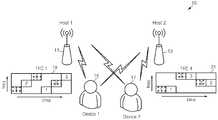
도 1을 참조하면, 통신 시스템, 예컨대 멀티-밴드 OFDM(Multi-band Orthogonal Frequency Division Multiplexing) 시스템(10)은 다수의 기지국(11과 13), 및 다수의 이동 단말(15과 17)을 포함한다.1, a communication system, for example, a
도 1과 도 2를 참조하면, 제1기지국(11)과 제1이동 단말(15)은 TFC1, 즉 "123123"의 호핑 패턴을 포함하는 패킷을 통하여 서로 통신하고, 제2기지국(13)과 제2이동 단말(17)은 TFC4, 즉 "113322"의 호핑 패턴을 포함하는 패킷을 통하여 서 로 통신한다.Referring to FIGS. 1 and 2, the
따라서, 도 3에 도시된 바와 같이, 동일한 시간대에 제1기지국(11)과 TCF1으로 통신하는 제1이동 단말(15)과, 제2기지국(17)과 TCF4로 통신하는 제2이동 단말(17)이 심벌 간 간섭(InterSymbol Interference(ISI))을 일으킬 수 있는 범위 내에 존재하게 되면, TFC1과 TFC4 각각에 포함된 6개의 심벌 중에서 최대 3개의 심벌 예컨대, 첫 번째 심벌(1), 세 번째 심벌(3), 및 다섯 번째 심벌(2)에서 ISI가 발생할 수 있다. 이하 상기 ISI를 심벌 간 충돌 또는 간단히 충돌(collision)이라 한다.3, the first
도 4는 패킷의 구조와 충돌이 일어날 때의 SNR 값을 나타낸다. 도 4의 (a)에 도시된 바와 같이, 패킷은 프리엠블(preamble), CE(channel estimation), 헤더 (header), 및 페이로드(payload)를 포함한다.4 shows the structure of the packet and the SNR value at the time of collision. As shown in FIG. 4A, the packet includes a preamble, a channel estimation (CE), a header, and a payload.
예컨대, 상기 프리엠블은 4개의 TFC(=4개의 호핑 패턴들), 즉 24개의 심벌을 포함하고, 상기 CE는 하나의 TFC(=하나의 호핑 패턴), 즉 6개의 심벌을 포함하고, 상기 헤더는 다수의 TFC들을 포함하고, 상기 페이로드는 다수의 TFC들을 포함한다.For example, the preamble includes four TFCs (= 4 hopping patterns), that is, 24 symbols, and the CE includes one TFC (= one hopping pattern), i.e. six symbols, Includes a plurality of TFCs, and the payload includes a plurality of TFCs.
도 4에 도시된 바와 같이 각각의 TFC1(=123123)의 첫 번째 심벌과 네 번째 심벌에서 충돌이 발생하는 경우라도, 종래의 수신기는 수신된 패킷에 포함된 모든 심벌들 각각에 대하여 고속 퓨리에 변환, 디매핑, 디인터리빙, 및 디코딩을 수행했다. 따라서 종래의 수신기는 불필요한 전력을 소비하는 문제점이 있었다.As shown in FIG. 4, even when a collision occurs between the first symbol and the fourth symbol of each TFC1 (= 123123), the conventional receiver performs fast Fourier transform (FFT) on all the symbols included in the received packet, Demapping, deinterleaving, and decoding. Therefore, the conventional receiver consumes unnecessary power.
따라서 본 발명이 이루고자 하는 기술적인 과제는 불필요하게 소비되는 전력을 감소시키기 위하여 수신된 패킷의 프리엠블에 포함된 심벌에서 충돌이 발생하는지의 여부에 따라 상기 패킷의 헤더 또는 페이로드에 포함된 심벌의 수신 여부를 제어할 수 있는 수신기와 상기 수신기의 동작을 제어하는 방법을 제공하는 것이다.SUMMARY OF THE INVENTION The present invention has been made in view of the above problems, and it is therefore an object of the present invention to provide a method and apparatus for reducing unnecessary power consumption, A receiver capable of controlling reception or not and a method of controlling the operation of the receiver.
상기 기술적 과제를 달성하기 위한 수신기의 동작을 제어하는 방법은 수신된 패킷의 프리엠블에 포함된 호핑 패턴의 N(N은 자연수)번째 심벌의 SNR(Signal to Noise Ratio) 값에 기초하여 동작 제어신호를 발생하는 단계와, 수신부가 상기 동작 제어신호에 응답하여 상기 패킷의 헤더와 페이로드에 포함된 다수의 호핑 패턴 각각의 N번째 심벌의 수신 여부를 제어하는 단계를 포함한다.According to another aspect of the present invention, there is provided a method of controlling an operation of a receiver, the method comprising: receiving an operation control signal based on a SNR (Signal to Noise Ratio) value of N (N is a natural number) symbol of a hopping pattern included in a preamble of a received packet; And controlling reception of the Nth symbol of each of the plurality of hopping patterns included in the header and payload of the packet in response to the operation control signal.
상기 동작 제어신호를 발생하는 단계는 상기 프리엠블에 포함된 상기 호핑 패턴의 상기 N번째 심벌의 상기 SNR 값을 측정하는 단계와, 측정된 SNR 값과 기준 SNR 값을 비교하여 비교신호를 발생하는 단계와, 상기 비교신호와 클락 신호에 기초하여 상기 동작 제어신호를 발생하는 단계를 포함한다.Generating the operation control signal comprises: measuring the SNR value of the Nth symbol of the hopping pattern included in the preamble; comparing the measured SNR value with a reference SNR value to generate a comparison signal; And generating the operation control signal based on the comparison signal and the clock signal.
상기 동작 제어신호는 상기 수신부에 구현된 고속 퓨리에 변환기로 공급되는 클락 신호이거나 또는 접지 전압 레벨을 갖는 신호이다.The operation control signal is a clock signal supplied to the FFT unit implemented in the receiving unit or a signal having a ground voltage level.
상기 기술적 과제를 달성하기 위한 수신기의 동작을 제어하는 방법은 패킷의 프리엠블에 포함된 호핑 패턴의 N(N은 자연수)번째 심벌의 SNR 값과 상기 패킷의 CE(channel estimation)에 포함된 호핑 패턴의 평균 SNR 값에 기초하여 동작 제어신호를 발생하는 단계와, 수신부가 상기 동작 제어신호에 응답하여 상기 패킷의 헤 더과 페이로드에 포함된 다수의 호핑 패턴 각각의 N번째 심벌의 수신 여부를 제어하는 단계를 포함한다.According to another aspect of the present invention, there is provided a method of controlling an operation of a receiver, the method comprising: receiving an SNR value of an N (N is a natural number) symbol of a hopping pattern included in a preamble of a packet and a hopping pattern Generating an operation control signal based on an average SNR value of the hopping pattern of the packet and a reception unit for controlling whether to receive an Nth symbol of each of a plurality of hopping patterns included in a header of the packet and a payload in response to the operation control signal .
상기 동작 제어신호를 발생하는 단계는 상기 프리엠블에 포함된 상기 호핑 패턴의 상기 N번째 심벌의 상기 SNR 값을 측정하고 측정된 SNR 값과 제1기준 SNR값을 비교하여 제1비교 신호를 발생하는 단계와, 상기 패킷의 상기 CE에 포함된 상기 호핑 패턴의 상기 평균 SNR값을 계산하고 계산된 SNR값과 제2기준 SNR값을 비교하여 제2비교 신호를 발생하는 단계와, 상기 제1비교 신호, 상기 제2비교 신호, 및 클락 신호의 조합에 기초하여 상기 동작 제어신호를 발생하는 단계를 포함한다.Wherein generating the operation control signal comprises: measuring the SNR value of the Nth symbol of the hopping pattern included in the preamble; comparing the measured SNR value with a first reference SNR value to generate a first comparison signal; Calculating the average SNR value of the hopping pattern included in the CE of the packet and comparing the calculated SNR value with a second reference SNR value to generate a second comparison signal; And generating the operation control signal based on a combination of the second comparison signal and the clock signal.
상기 기술적 과제를 달성하기 위한 수신기는 패킷의 프리엠블에 포함된 호핑 패턴의 N(N은 자연수)번째 심벌의 SNR 값에 기초하여 동작 제어신호를 발생하는 동작 제어신호 발생기와, 상기 동작 제어신호에 응답하여 상기 패킷의 헤더와 페이로드에 포함된 다수의 호핑 패턴 각각의 N번째 심벌의 수신 여부를 제어하는 수신부를 포함한다.According to an aspect of the present invention, there is provided a receiver including an operation control signal generator for generating an operation control signal based on an SNR value of N (N is a natural number) symbol of a hopping pattern included in a preamble of a packet, And a receiver for controlling whether to receive an Nth symbol of each of a plurality of hopping patterns included in a header and a payload of the packet in response to the packet.
상기 동작 제어신호 발생기는 상기 프리엠블에 포함된 상기 호핑 패턴의 상기 N번째 심벌의 상기 SNR값을 계산하고, 계산된 SNR값과 기준 SNR값을 비교하여 비교 신호를 발생하기 위한 SNR 계산기와, 상기 SNR 계산기로부터 출력된 상기 비교 신호와 클락 신호에 응답하여 상기 동작 제어신호를 발생하기 위한 논리 게이트를 포함한다.Wherein the operation control signal generator includes an SNR calculator for calculating the SNR value of the Nth symbol of the hopping pattern included in the preamble and comparing the calculated SNR value with a reference SNR value to generate a comparison signal, And a logic gate for generating the operation control signal in response to the comparison signal and the clock signal output from the SNR calculator.
상기 수신부는 상기 동작 제어신호에 응답하여 인에이블 또는 디스에이블되는 패스트 프리에 변환기를 포함한다.The receiver includes a fast-free converter that is enabled or disabled in response to the operation control signal.
다른 실시 예에서, 상기 동작 제어신호 발생기는 선택 신호에 응답하여 상기 패킷의 상기 프리엠블 또는 상기 패킷의 CE를 출력하기 위한 디먹스와, 상기 디먹스로부터 출력된 상기 프리엠블에 포함된 호핑 패턴의 N번째 심벌의 SNR값을 계산하고, 계산된 SNR값과 제1기준 SNR값을 비교하여 제1비교 신호를 발생하기 위한 제1 SNR 계산기와, 상기 디먹스로부터 출력된 상기 CE에 포함된 호핑 패턴의 평균 SNR값을 계산하기 위한 제2 SNR 계산기와, 상기 제2 SNR 계산기로부터 출력된 상기 평균 SNR값과 제2기준 SNR값을 비교하고 제2비교 신호를 출력하기 위한 비교기와, 상기 제1비교 신호와 상기 제2비교 신호와 및 클락 신호의 조합에 응답하여 상기 동작 제어신호를 발생하기 위한 논리 게이트를 포함한다.In another embodiment, the operation control signal generator includes a demux for outputting the preamble of the packet or the CE of the packet in response to the selection signal, and a hopping pattern of the hopping pattern included in the preamble output from the demux A first SNR calculator for calculating an SNR value of an Nth symbol, comparing the calculated SNR value with a first reference SNR value to generate a first comparison signal, and a first SNR calculator for calculating a hopping pattern A second comparator for comparing the average SNR value output from the second SNR calculator with a second reference SNR value and outputting a second comparison signal; And a logic gate for generating the operation control signal in response to a combination of the signal, the second comparison signal, and the clock signal.
상기 수신부는 상기 동작 제어신호에 응답하여 인에이블 또는 디스에이블되는 패스트 프리에 변환기를 포함한다. 상기 N은 1 내지 6중에서 어느 하나이다.The receiver includes a fast-free converter that is enabled or disabled in response to the operation control signal. And N is any one of 1 to 6.
본 발명의 실시 예에 따른 수신기는 패킷의 프리엠블에 포함되며 충돌이 발생한 심벌의 위치를 검출하고 상기 패킷의 헤더 또는 페이로드에 포함되며 검출된 위치에 해당하는 심벌에 대한 처리, 예컨대 고속 퓨리에 변환, 디매핑, 및 디인터리빙을 제어할 수 있으므로 상기 수신기에서 소비되는 전력을 상당히 감소시킬 수 있는 효과가 있다.A receiver according to an exemplary embodiment of the present invention detects a position of a collision-incurred symbol included in a preamble of a packet and processes the symbol included in the header or payload of the packet and corresponding to the detected position, for example, a fast Fourier transform Demapping, and deinterleaving can be controlled, so that the power consumed by the receiver can be significantly reduced.
본 발명과 본 발명의 동작상의 이점 및 본 발명의 실시에 의하여 달성되는 목적을 충분히 이해하기 위해서는 본 발명의 바람직한 실시 예를 예시하는 첨부 도 면 및 첨부 도면에 기재된 내용을 참조하여야만 한다.In order to fully understand the present invention, operational advantages of the present invention, and objects achieved by the practice of the present invention, reference should be made to the accompanying drawings, which illustrate preferred embodiments of the present invention, and the contents of the accompanying drawings.
이하, 첨부한 도면을 참조하여 본 발명의 바람직한 실시 예를 설명함으로써, 본 발명을 상세히 설명한다. 각 도면에 제시된 동일한 참조부호는 동일한 부재를 나타낸다.BEST MODE FOR CARRYING OUT THE INVENTION Hereinafter, the present invention will be described in detail with reference to the preferred embodiments of the present invention with reference to the accompanying drawings. Like reference symbols in the drawings denote like elements.
도 5는 본 발명의 실시 예에 따른 수신기의 개략적인 블록 도를 나타낸다. 도 5를 참조하면, OFDM 수신기 또는 멀티-밴드 OFDM 수신기로서 사용될 수 있는 수신기(30)는 안테나(31), 동기부(33), 동작 제어신호 발생기(35), 및 수신부(49)를 포함한다. 수신기(30)는 안테나(31)와 동기부(33) 사이에 구현된 아날로그 디지털 변환기(미 도시)를 더 포함할 수 있다.5 shows a schematic block diagram of a receiver according to an embodiment of the present invention. 5, a
동기부(33)는 기지국으로부터 출력되고 채널과 안테나(31)를 통하여 입력된 패킷, 예컨대, 도 4의 (a)의 구조를 갖는 패킷을 수신하고, 수신된 패킷의 프리엠블과 CE(channel estimation)를 순차적으로 동작 제어신호 발생기(35)로 출력한 후, 헤더와 페이로드를 순차적으로 수신부(49)로 전송한다.The
클락 신호(CLK) 또는 접지 전압 레벨을 갖는 동작 제어신호(OCS)를 수신부 (49)로 공급할 수 있는 동작 제어신호 발생기(35)는 디먹스(DEMUX) (demultiplexer); 37), 제1SNR 계산기(39), 제2SNR 계산기(41), 비교기(43), 제1논리 게이트(45), 및 제2논리 게이트(47)를 포함한다. 실시 예에 따라서 제1논리 게이트(45)와 제2논리 게이트(47)는 하나의 논리 게이트로 구현될 수도 있다.The operation
디먹스(37)는 동기부(33)로부터 출력된 선택 신호(SEL), 예컨대 제1레벨(예컨대, 하이 레벨)을 갖는 선택 신호(SEL)에 응답하여 수신된 패킷의 프리엠블을 제 1SNR 계산기(39)로 출력한다.The
충돌 검출기라고도 불리는 제1SNR 계산기(39)는 디먹스(37)로부터 출력된 프리엠블의 호핑 패턴을 구성하는 M(M은 자연수, 예컨대 M=6)개의 심벌들 각각의 SNR 값(예컨대, dB)을 측정하고, 측정된 M(예컨대, M=6)개의 SNR 값들 각각과 기준 SNR 값(REF_SNR)을 비교하고, 각각의 비교 결과에 따른 M(예컨대, M=6)-비트 데이터를 내부 메모리(미도시)에 저장한다. 여기서, 기준 SNR 값(REF_SNR)은 조절 가능한 값이다.The
즉, 제1SNR 계산기(39)는 심벌 단위로 SNR 값을 측정하고, 측정된 SNR 값과 기준 SNR 값(REF_SNR)을 비교하고, 비교 결과에 따라 데이터 "0" 또는 데이터 "1"을 생성한다.That is, the
일반적으로, 충돌이 발생하는 심벌의 SNR 값은 충돌이 발생하지 않는 심벌의 SNR 값보다 작다. 본 명세서에서는 설명의 편의를 위하여, 기준 SNR 값(REF_SNR)을 충돌이 발생한 심벌에 대해 측정된 SNR 값보다 낮게 설정하고, 측정된 SNR값이 기준 SNR 값(REF_SNR)보다 크거나 같을 때 양자의 비교 결과에 따라 데이터 "0"을 생성하고 그외의 경우에는 데이터 "1"을 생성한다고 가정한다.Generally, the SNR value of a symbol in which a collision occurs is smaller than the SNR value of a symbol in which no collision occurs. For the sake of convenience of explanation, the reference SNR value (REF_SNR) is set to be lower than the SNR value measured for the symbol in which the collision occurs, and when the measured SNR value is equal to or greater than the reference SNR value (REF_SNR) And generates data "0" in accordance with the result and generates data "1 " in other cases.
여기서, 데이터 "0"은 다른 이동 장치의 심벌과 충돌을 일으키는 심벌을 나타내고, 데이터 "1"은 상기 다른 이동 장치의 심벌과 충돌을 일으키지 않은 심벌을 나타낸다.Here, the data " 0 "represents a symbol causing a collision with a symbol of another mobile apparatus, and the data" 1 " represents a symbol which does not conflict with the symbol of the other mobile apparatus.
즉, 제1SNR 계산기(39)는 채널을 통하여 수신된 패킷의 프리엠블의 호핑 패턴의 N(N은 자연수, 예컨대 N=1~6)번째 심벌의 SNR 값을 측정하고, 측정된 SNR 값 과 기준 SNR 값(REF_SNR)을 비교하고, 비교 결과에 따라 데이터 "0" 또는 데이터 "1"을 생성하고, 생성된 데이터 "0" 또는 데이터 "1"을 SNR 계산기(39)의 내부에 구현된 내부 메모리, 예컨대 레지스터 또는 래치에 저장한다(도 8의 S10).That is, the
프리엠블은 반복적인 호핑 패턴들, 예컨대 네 개의 호핑 패턴들(예컨대, 4*TFC1)을 포함하므로, 제1SNR 계산기(39)는 하나의 호핑 패턴에 대한 M-비트 데이터를 생성하고, 생성된 M-비트 데이터를 내부의 메모리에 저장할 수 있다.Since the preamble includes repetitive hopping patterns, e.g., four hopping patterns (e.g., 4 * TFC1), the
예컨대, 상기 내부 메모리에 저장된 6-비트 데이터가 "011011"인 경우, 수신된 패킷에 포함된 각각의 호핑 패턴(예컨대, 도 7의 "123123")의 첫 번째 심벌 (SB1)과 네 번째 심벌(SB4)에서 충돌이 일어남을 알 수 있다. 따라서, 제1SNR 계산기(39)는 심벌 단위(symbol-by-symbol)로 충돌 발생 여부와 충돌 발생 위치를 측정(또는 검출)할 수 있다.For example, when 6-bit data stored in the internal memory is "011011 ", the first symbol SB1 and the fourth symbol SB1 of each hopping pattern (e.g.," 123123 " SB4) can be seen to occur. Therefore, the
제1SNR 계산기(39)의 내부 메모리에 M(예컨대, M=6)-비트 데이터가 저장된 후, 디먹스(37)는 동기부(33)로부터 출력된 선택 신호(SEL), 예컨대 제2레벨(예컨대, 로우 레벨)을 갖는 선택 신호(SEL)에 응답하여 수신된 패킷의 CE를 제2SNR 계산기(41)로 출력한다.After the M (e.g., M = 6) -bit data is stored in the internal memory of the
제2SNR 계산기(41)는 호핑 패턴을 구성하는 M(M은 자연수, 예컨대 M=6)개의 심벌들 각각의 SNR 값을 측정하고, 측정된 SNR 값들로부터 평균 SNR 값(예컨대, dB)을 계산한다(도 8의 S20). 제2SNR 계산기(41)는 CE의 링크 질(link quality)을 측정할 수 있으므로 충돌 여부에 대한 정확도를 더 높일 수 있다. 따라서, 제2SNR 계산기(41)는 링크 질 지시자(link quality indicator)로서의 기능을 수행할 수 있 다.The
비교기(43)는 제2SNR 계산기(41)에 의하여 계산된 평균 SNR 값과 제2기준 SNR 값(REF)을 수신하고, 이들을 비교하고, 비교 신호를 출력한다(도 8의 S20).The
예컨대, 평균 SNR 값이 제2기준 SNR 값(REF)보다 같거나 클 때 비교기(43)는 제1레벨을 갖는 비교 신호를 출력하고, 그 반대의 경우에는 제2레벨을 갖는 비교 신호를 출력할 수 있다. 또한, 제2기준 SNR 값(REF)을 제1평균 SNR 값(즉, 충돌이 발생하는 적어도 하나의 심벌을 포함하는 호핑 패턴의 평균 SNR 값)보다 낮게 제2평균 SNR 값(즉, 충돌이 발생하는 심벌을 하나도 포함하지 않는 호핑 패턴의 평균 SNR 값)보다 높게 설정할 수 있다.For example, when the average SNR value is equal to or greater than the second reference SNR value REF, the
따라서, 패킷의 CE의 호핑 패턴 내에 충돌이 발생하는 적어도 하나의 심벌이 포함된 경우, 비교기(43)는 제1레벨(예컨대, 하이 레벨)을 갖는 비교 신호를 출력한다.Therefore, when at least one symbol in which a collision occurs in the hopping pattern of the CE of the packet is included, the
제1논리 게이트(45)는 제1SNR 계산기로부터 순차적으로 출력되는 M(예컨대, M=6)-비트 데이터와 비교기(43)로부터 출력된 비교 신호를 논리곱 연산하고, 연산 결과에 따른 신호를 출력한다. 제2논리 게이트(47)는 제1논리 게이트(45)로부터 출력된 신호와 클락 신호(CLK)를 논리곱 연산하고, 연산 결과에 따른 동작 제어신호(OCS)를 출력한다(도 8의 S30).The
예컨대, 제1SNR 계산기(39)에 의하여 계산된 TFC1에 해당하는 호핑 패턴 (123123) 각각에 대한 비교 결과가 "011011"이고, 비교기(43)로부터 출력된 비교신호가 제1레벨을 갖는 경우, 패킷의 헤더 또는 상기 패킷의 페이로드에 포함된 각각 의 호핑 패턴의 첫 번째 심벌(도 7의 SB1) 또는 네 번째 심벌(도 7의 SB4)이 수신부(49)로 전송되는 동안, 제1논리 게이트(45)는 제2레벨을 갖는 신호를 출력하므로, 제2논리 게이트(47)는 제2레벨을 갖는 동작 제어신호(OCS)를 수신부(49)로 출력한다.For example, when the comparison result for each of the
따라서, 패킷의 헤더 또는 상기 패킷의 페이로드에 포함된 각각의 호핑 패턴의 첫 번째 심벌(도 7의 SB1) 또는 네 번째 심벌(도 7의 SB4)이 수신부(49)로 전송되는 동안, 수신부(49)에 구현된 고속 퓨리에 변환기(51), 디매퍼(Demapper; 53), 및 디인터리버(55) 각각은 제2레벨을 갖는 동작 제어신호(OCS)에 응답하여 디스에이블된다. 또한, 디코더(57)는 디코딩 동작을 수행하지 않는다.7) or the fourth symbol (SB4 in Fig. 7) of each hopping pattern included in the header of the packet or the payload of the packet is transmitted to the receiving
그러므로, 고속 퓨리에 변환기(51), 디매퍼(Demapper; 53), 디인터리버(55), 및 디코더(57) 각각에서 소비되는 전력은 감소한다(도 10 참조).Therefore, the power consumed by each of the high-speed Fourier
그러나, 제1SNR 계산기(39)에 의하여 계산된 TFC1에 해당하는 호핑 패턴 (123123) 각각에 대한 비교 결과가 "011011"이고, 비교기(43)로부터 출력된 비교신호가 제1레벨을 갖는 경우, 패킷의 헤더 또는 상기 패킷의 페이로드에 포함된 각각의 호핑 패턴의 두 번째 심벌(도 7의 SB2), 세 번째 심벌(도 7의 SB3), 다섯 번째 심벌(도 7의 SB5), 또는 여섯 번째 심벌(도 7의 SB6)이 수신부(49)로 전송되는 동안, 제1논리 게이트(45)는 제1레벨을 갖는 신호를 출력하므로, 제2논리 게이트(47)는 클락 신호(CLK)와 실질적으로 동일한 동작 제어신호(OCS)를 수신부(49)로 출력한다.However, if the comparison result for each of the hopping
따라서, 패킷의 헤더 또는 상기 패킷의 페이로드에 포함된 각각의 호핑 패턴 의 두 번째 심벌(도 7의 SB2), 세 번째 심벌(도 7의 SB3), 다섯 번째 심벌(도 7의 SB5), 또는 여섯 번째 심벌(도 7의 SB6)이 수신부(49)로 전송되는 동안, 수신부 (49)에 구현된 고속 퓨리에 변환기(51), 디매퍼(Demapper; 53), 및 디인터리버(55) 각각은 동작 제어신호(OCS)에 응답하여 정상적인 동작을 수행할 수 있다. 또한, 디코더(57)는 심벌이 입력될 때마다 디코딩 동작을 수행하므로 디코더(57)에서 소비되는 전력을 감소한다(도 10 참조).Therefore, the second symbol (SB2 in Fig. 7), the third symbol (SB3 in Fig. 7), the fifth symbol (SB5 in Fig. 7) of the header of the packet or the respective hopping patterns included in the payload of the packet The high-
즉, 수신부(49)는 충돌을 일으키는 심벌에 따라 서로 다른 상태를 갖는 동작 제어신호(OCS)에 응답하여 패킷의 헤더 또는 상기 패킷의 페이로드에 포함된 각각의 호핑 패턴의 N번째 심벌의 수신(또는 처리) 여부를 결정할 수 있다(도 8의 S40).That is, in response to the operation control signal OCS having different states according to the symbol causing the collision, the receiving
도 6은 본 발명의 다른 실시 예에 따른 수신기의 개략적인 블록 도를 나타내고, 도 9는 본 발명의 다른 실시 예에 따른 수신기의 동작 제어 방법을 설명하기 위한 흐름도이다.FIG. 6 is a schematic block diagram of a receiver according to another embodiment of the present invention, and FIG. 9 is a flowchart illustrating a method of controlling an operation of a receiver according to another embodiment of the present invention.
먼저, 도 6을 참조하면, 수신기(30A)는 안테나(31), 동기부(33), 충돌 검출기라고도 불리는 SNR 계산기(39), 논리 게이트(47), 및 수신부(49)를 포함한다. SNR 계산기(39)와 논리 게이트(47)는 동작 제어신호(OCS)를 발생하는 동작 제어신호 발생기의 기능을 수행한다.6, the
동기부(33)는 기지국으로부터 출력되고 채널과 안테나(31)를 통하여 수신된 패킷의 프리엠블을 SNR 계산기(39)로 전송한다.The
SNR 계산기(39)는 패킷의 프리엠블의 호핑 패턴의 N(N은 자연수, 예컨대 N=1~6)번째 심벌의 SNR 값을 측정하고, 측정된 SNR 값과 기준 SNR 값(REF_SNR)을 비교하고, 비교 결과에 따라 데이터 "0" 또는 데이터 "1"을 생성하고 생성된 데이터를 SNR 계산기(39)의 내부에 구현된 내부 메모리에 저장한다(도 9의 S110). 상술한 바와 같이, 데이터 "0"은 다른 이동 단말로 전송되는 심벌과 충돌을 일으키는 심벌을 나타낸다고 가정한다.The
예컨대, SNR 계산기(39)에 의하여 계산된 TFC1에 해당하는 호핑 패턴 (123123) 각각에 대한 비교 결과가 "011011"인 경우, 논리 게이트(47)는 비교 결과와 클락 신호(CLK)에 응답하여 동작 제어신호(OCS)를 발생한다(도 9의 S120).For example, when the comparison result for each of the hopping
동기부(33)는 헤더와 페이로드를 순차적으로 수신부(49)로 전송한다.The synchronizing
수신부(49)는 동작 제어신호(OCS)에 응답하여 패킷의 헤더 또는 페이로드에 포함된 각각의 호핑 패턴의 N번째 심벌의 수신 여부를 결정한다(도 9의 S130).The receiving
도 7에 도시된 바와 같이, 수신된 패킷의 헤더 또는 페이로드에 포함된 다수의 호핑 패턴들 각각의 첫 번째 심벌(도 7의 SB1) 또는 네 번째 심벌(도 7의 SB4)이 수신부(49)의 고속 퓨리에 변환기(51)로 전송되기 직전 또는 직후에 논리 게이트(47)는 제2레벨을 갖는 동작 제어신호(OCS)를 고속 퓨리에 변환기(51)로 공급한다.As shown in Fig. 7, the first symbol (SB1 in Fig. 7) or the fourth symbol (SB4 in Fig. 7) of each of a plurality of hopping patterns included in the header or payload of the received packet is received by the
따라서, 고속 퓨리에 변환기(51)는 제2레벨을 갖는 동작 제어신호(OCS)에 응답하여 디스에이블된다. 즉, 수신된 패킷의 헤더 또는 페이로드에 포함된 각각의 호핑 패턴의 첫 번째 심벌(도 7의 SB1) 또는 네 번째 심벌(도 7의 SB4)이 고속 퓨리에 변환기(51)로 전송되는 동안, 논리 게이트(47)는 클락 신호(CLK)를 고속 퓨리 에 변환기(51)로 공급하지 않는다. 따라서, 수신부(49)에서 소비되는 전력을 감소한다.Therefore, the
본 발명의 실시 예에 따른 수신기(30A)의 수신부(49)는 각각의 호핑 패턴 중에서 다른 이동 단말로 전송되는 심벌과 충돌을 일으키는 심벌을 수신하지 않으므로, 수신기(30A)에서 소비되는 전력은 감소한다.Since the
수신된 패킷의 헤더 또는 페이로드에 포함된 각각의 호핑 패턴의 두 번째 심벌(도 7의 SB2), 세 번째 심벌(도 7의 SB3), 다섯 번째 심벌(도 7의 SB5), 또는 여섯 번째 심벌(도 7의 SB6)이 고속 퓨리에 변환기(51)로 전송되기 직전 또는 직후에, 논리 게이트(47)는 클락 신호(CLK)와 실질적으로 동일한 동작 제어신호(OCS)를 고속 퓨리에 변환기(51)로 공급한다.The second symbol (SB2 in Fig. 7), the third symbol (SB3 in Fig. 7), the fifth symbol (SB5 in Fig. 7), or the sixth symbol The
따라서, 고속 퓨리에 변환기(51)는 동작 제어신호(OCS), 즉 클락 신호(CLK)에 응답하여 수신된 패킷의 헤더 또는 페이로드에 포함된 각각의 호핑 패턴의 두 번째 심벌(도 7의 SB2), 세 번째 심벌(도 7의 SB3), 다섯 번째 심벌(도 7의 SB5), 또는 여섯 번째 심벌(도 7의 SB6)에 대하여 고속 퓨리에 변환을 수행하고 고속 퓨리에 변환된 신호를 출력한다.7) of the respective hopping patterns included in the header or payload of the packet received in response to the operation control signal OCS, that is, the clock signal CLK, the high-
즉, 헤더 또는 페이로드에 포함된 각각의 호핑 패턴에서 충돌이 발생하지 않는 두 번째 심벌(도 7의 SB2), 세 번째 심벌(도 7의 SB3), 다섯 번째 심벌(도 7의 SB5), 또는 여섯 번째 심벌(도 7의 SB6)이 고속 퓨리에 변환기(51)로 전송되는 동안, 논리 게이트(47)는 클락 신호(CLK)를 고속 퓨리에 변환기(51)로 공급한다.In other words, the second symbol (SB2 in Fig. 7), the third symbol (SB3 in Fig. 7), the fifth symbol (SB5 in Fig. 7), or the third symbol While the sixth symbol (SB6 in Fig. 7) is transmitted to the
도 7은 종래의 수신기에서 소비되는 전력(A)과, 도 5 또는 도 6에 도시된 본 발명의 실시 예에 따른 수신기에서 소비되는 전력(B)을 나타낸다. 도 10은 종래의 수신기에서 소비되는 전력의 예(C)과 도 5 또는 도 6에 도시된 본 발명의 실시 예에 따른 수신기에서 소비되는 전력의 예(D)를 나타낸다.FIG. 7 shows power (A) consumed in a conventional receiver and power (B) consumed in a receiver according to an embodiment of the present invention shown in FIG. 5 or 6. FIG. 10 shows an example (C) of power consumed in a conventional receiver and an example (D) of power consumed in a receiver according to an embodiment of the present invention shown in FIG. 5 or 6.
도 7과 도 10을 참조하면, 수신부로 공급되는 클락 신호(CLK)를 게이팅하기 위한 동작 제어 신호 발생기를 포함하지 않는 종래의 수신기는, 패킷의 헤더 또는 페이로드에 포함된 각각의 호핑 패턴의 첫 번째 심벌(SB1)과 네 번째 심벌 (SB4)에서 충돌이 발생하는 경우라도, 첫 번째 심벌(SB1)과 네 번째 심벌(SB4)을 처리하기 위한 클락 신호 (CLK)를 수신부, 예컨대 고속 퓨리에 변환기, 디매퍼, 및 디인터리버로 공급한다. 따라서, 종래의 수신기는 충돌이 발생한 심벌을 처리하기 위한 전력을 소비했다.7 and 10, a conventional receiver that does not include an operation control signal generator for gating a clock signal CLK supplied to a receiver has a first header of each hopping pattern included in a packet header or a payload, Even if a collision occurs in the first symbol SB1 and the fourth symbol SB4, the clock signal CLK for processing the first symbol SB1 and the fourth symbol SB4 may be received by a receiving unit such as a high-speed Fourier transformer, Demapper, and deinterleaver. Thus, the conventional receiver has consumed power to process the symbol in which the collision occurred.
그러나, 도 5 또는 도 6에 도시된 바와 같이 수신부(49)로 공급되는 클락 신호(CLK)를 게이팅하기 위한 동작 제어신호 발생기(35)를 포함하는 수신기(30 또는 30A)는, 패킷의 헤더 또는 페이로드에 포함된 각각의 호핑 패턴의 첫 번째 심벌(SB1)과 네 번째 심벌 (SB4)에서 충돌이 발생하는 경우, 충돌이 발생한 심벌을 처리하기 위한 클락 신호(CLK)를 수신부(49)로 공급하지 않는다.However, the
도 10은 도 1에 도시된 제1기지국(11)과 제1이동 단말(15)이 TFC1을 사용하고, 제2기지국(13)과 제2이동 단말(17)이 TFC4를 사용하는 경우에 제1이동 단말 (15) 또는 제2이동 단말(17)에서 소비되는 전력을 나타낸 것이다.10 shows a case where the
종래의 수신기에 비하여 본 발명의 실시 예에 따른 수신기, 예컨대 고속 퓨리에 변환기(FFT; 51)에서 소비되는 전력은 43mW에서 21.5mW로 감소하고, 디매 퍼(53)에서 소비되는 전력은 18mW에서 9mW로 감소하고, 디인터리버(55)에서 소비되는 전력은 9mW에서 4.5mW로 감소하고, 비터비 디코더(57)에서 소비되는 전력은 1.8mW에서 0.9mW로 감소함을 알 수 있다.The power consumed by the receiver, for example, the FFT (Fast Fourier Transform) 51 according to the embodiment of the present invention is reduced from 43 mW to 21.5 mW, and the power consumed by the
상술한 바와 같이, 본 발명의 실시 예에 따른 수신기(30, 또는 30A)는 선택적으로 심벌을 수신부(49)로 전송하므로 수신기(30, 또는 30A)에서 소비되는 전력을 감소시킬 수 있다.As described above, the
본 발명은 도면에 도시된 일 실시 예를 참고로 설명되었으나 이는 예시적인 것에 불과하며, 본 기술 분야의 통상의 지식을 가진 자라면 이로부터 다양한 변형 및 균등한 타 실시 예가 가능하다는 점을 이해할 것이다. 따라서, 본 발명의 진정한 기술적 보호 범위는 첨부된 등록청구범위의 기술적 사상에 의해 정해져야 할 것이다.While the present invention has been particularly shown and described with reference to exemplary embodiments thereof, it is to be understood that the invention is not limited to the disclosed embodiments, but, on the contrary, is intended to cover various modifications and equivalent arrangements included within the spirit and scope of the appended claims. Accordingly, the true scope of the present invention should be determined by the technical idea of the appended claims.
본 발명의 상세한 설명에서 인용되는 도면을 보다 충분히 이해하기 위하여 각 도면의 상세한 설명이 제공된다.DETAILED DESCRIPTION OF THE PREFERRED EMBODIMENTS In order to more fully understand the drawings recited in the detailed description of the present invention, a detailed description of each drawing is provided.
도 1은 심벌 간 충돌이 발생할 수 있는 일반적인 통신 시스템의 개략적인 블록 도이다.Figure 1 is a schematic block diagram of a typical communication system in which collision between symbols can occur.
도 2는 TFC(Time-Frequency Code)와 호핑 패턴(hopping pattern)의 리스트를 나타낸다.FIG. 2 shows a list of a time-frequency code (TFC) and a hopping pattern.
도 3은 도 1에 도시된 통신 시스템에서 심벌 간 충돌이 발생하는 경우를 설명하기 위한 도면이다.FIG. 3 is a view for explaining a case where an intersymbol collision occurs in the communication system shown in FIG. 1. FIG.
도 4는 패킷의 구조와 심벌 간 충돌이 일어날 때의 SNR 값을 나타낸다.FIG. 4 shows the SNR value when the structure of the packet and the collision between symbols occurs.
도 5는 본 발명의 실시 예에 따른 수신기의 개략적인 블록 도를 나타낸다.5 shows a schematic block diagram of a receiver according to an embodiment of the present invention.
도 6은 본 발명의 다른 실시 예에 따른 수신기의 개략적인 블록 도를 나타낸다.Figure 6 shows a schematic block diagram of a receiver according to another embodiment of the present invention.
도 7은 심벌 간 충돌이 발생할 때 종래의 수신기에서 소비되는 전력과 도 5 또는 도 6에 도시된 본 발명의 실시 예에 따른 수신기에서 소비되는 전력을 나타낸다.FIG. 7 shows the power consumed in a conventional receiver when an intersymbol collision occurs and the power consumed in a receiver according to an embodiment of the present invention shown in FIG. 5 or 6.
도 8은 본 발명의 실시 예에 따른 수신기의 동작 제어 방법을 설명하기 위한 흐름도이다.8 is a flowchart illustrating a method of controlling an operation of a receiver according to an embodiment of the present invention.
도 9는 본 발명의 다른 실시 예에 따른 수신기의 동작 제어 방법을 설명하기 위한 흐름도이다.9 is a flowchart illustrating a method of controlling an operation of a receiver according to another embodiment of the present invention.
도 10은 심벌 간 충돌이 발생할 때 종래의 수신기에서 소비되는 전력의 예와 도 5 또는 도 6에 도시된 본 발명의 실시 예에 따른 수신기에서 소비되는 전력의 예를 나타낸다.FIG. 10 shows an example of power consumed in a conventional receiver when an intersymbol collision occurs, and an example of power consumed in a receiver according to an embodiment of the present invention shown in FIG. 5 or FIG.
Claims (18)
Translated fromKoreanPriority Applications (2)
| Application Number | Priority Date | Filing Date | Title |
|---|---|---|---|
| KR1020080026001AKR101410697B1 (en) | 2008-03-20 | 2008-03-20 | Receiver and method of controlling operation of said receiver |
| US12/379,144US8259880B2 (en) | 2008-03-20 | 2009-02-13 | Receivers and methods for controlling operation of receivers |
Applications Claiming Priority (1)
| Application Number | Priority Date | Filing Date | Title |
|---|---|---|---|
| KR1020080026001AKR101410697B1 (en) | 2008-03-20 | 2008-03-20 | Receiver and method of controlling operation of said receiver |
Publications (2)
| Publication Number | Publication Date |
|---|---|
| KR20090100682A KR20090100682A (en) | 2009-09-24 |
| KR101410697B1true KR101410697B1 (en) | 2014-07-02 |
Family
ID=41088923
Family Applications (1)
| Application Number | Title | Priority Date | Filing Date |
|---|---|---|---|
| KR1020080026001AExpired - Fee RelatedKR101410697B1 (en) | 2008-03-20 | 2008-03-20 | Receiver and method of controlling operation of said receiver |
Country Status (2)
| Country | Link |
|---|---|
| US (1) | US8259880B2 (en) |
| KR (1) | KR101410697B1 (en) |
Families Citing this family (1)
| Publication number | Priority date | Publication date | Assignee | Title |
|---|---|---|---|---|
| US8948039B2 (en) | 2012-12-11 | 2015-02-03 | Qualcomm Incorporated | Packet collisions and impulsive noise detection |
Citations (2)
| Publication number | Priority date | Publication date | Assignee | Title |
|---|---|---|---|---|
| KR20060005264A (en)* | 2004-07-12 | 2006-01-17 | 삼성전자주식회사 | Method and system for setting dedicated channel transmit power in mobile communication system |
| KR20070090520A (en)* | 2006-03-03 | 2007-09-06 | 삼성전자주식회사 | Apparatus and method for measuring received signal-to-noise and interference ratio using preamble in mobile communication system |
Family Cites Families (12)
| Publication number | Priority date | Publication date | Assignee | Title |
|---|---|---|---|---|
| JP3338374B2 (en) | 1997-06-30 | 2002-10-28 | 松下電器産業株式会社 | Arithmetic processing method and apparatus |
| JP2002314436A (en) | 2001-04-11 | 2002-10-25 | Matsushita Electric Ind Co Ltd | Soft decision decoding apparatus and soft decision decoding method |
| JP3847181B2 (en) | 2002-02-22 | 2006-11-15 | 沖電気工業株式会社 | Soft decision Viterbi decoding device |
| JP2003289292A (en) | 2002-03-28 | 2003-10-10 | Seiko Epson Corp | Viterbi decoding method, short-range wireless communication device and wireless communication method using the same |
| JP4000067B2 (en) | 2003-01-30 | 2007-10-31 | 三洋電機株式会社 | Receiving method and apparatus |
| US20050176371A1 (en)* | 2004-02-09 | 2005-08-11 | Arto Palin | Synchronization of time-frequency codes |
| US8144572B2 (en)* | 2004-09-14 | 2012-03-27 | Qualcomm Incorporated | Detection and mitigation of interference and jammers in an OFDM system |
| CN101151821A (en)* | 2005-03-28 | 2008-03-26 | 株式会社泛泰 | Multi-access digital communication method used in ultra-broadband wireless access network |
| US7564775B2 (en)* | 2005-04-29 | 2009-07-21 | Qualcomm, Incorporated | Timing control in orthogonal frequency division multiplex systems based on effective signal-to-noise ratio |
| US20070042795A1 (en)* | 2005-08-19 | 2007-02-22 | Mo Shaomin S | Method of band multiplexing to improve system capacity for a multi-band communication system |
| WO2008068669A1 (en)* | 2006-12-01 | 2008-06-12 | Koninklijke Philips Electronics, N.V. | Improving performance in a time-frequency interleaved orthogonal frequency division multiplexing system |
| JP4577350B2 (en)* | 2007-11-27 | 2010-11-10 | ソニー株式会社 | Reception device, communication system, reception method, and program |
- 2008
- 2008-03-20KRKR1020080026001Apatent/KR101410697B1/ennot_activeExpired - Fee Related
- 2009
- 2009-02-13USUS12/379,144patent/US8259880B2/ennot_activeExpired - Fee Related
Patent Citations (2)
| Publication number | Priority date | Publication date | Assignee | Title |
|---|---|---|---|---|
| KR20060005264A (en)* | 2004-07-12 | 2006-01-17 | 삼성전자주식회사 | Method and system for setting dedicated channel transmit power in mobile communication system |
| KR20070090520A (en)* | 2006-03-03 | 2007-09-06 | 삼성전자주식회사 | Apparatus and method for measuring received signal-to-noise and interference ratio using preamble in mobile communication system |
Also Published As
| Publication number | Publication date |
|---|---|
| US8259880B2 (en) | 2012-09-04 |
| US20090238316A1 (en) | 2009-09-24 |
| KR20090100682A (en) | 2009-09-24 |
Similar Documents
| Publication | Publication Date | Title |
|---|---|---|
| US11177993B2 (en) | Apparatus for radio frequency receiver with improved timing recovery and frequency offset estimation and associated methods | |
| US8744020B2 (en) | Frequency offset estimation | |
| JP4970431B2 (en) | Signal detection apparatus and signal detection method | |
| Jimenez et al. | Design and implementation of synchronization and AGC for OFDM-based WLAN receivers | |
| US20100202301A1 (en) | Method for switching between a long guard interval and a short guard interval and module using the same | |
| US20060199558A1 (en) | Apparatus and method for detecting preambles according to IEEE 802.11A/B/G wireless LAN standards and its application to a 802.11 multimode receiver | |
| JP5861301B2 (en) | Wireless communication terminal and automatic gain control method | |
| US20060072450A1 (en) | Ofdm signal collision position detection apparatus and ofdm reception device | |
| US8711718B2 (en) | Method and apparatus for reducing power consumption used in communication system having time slots | |
| KR100841988B1 (en) | Method and system for reducing collisions in an asynchronous communication system | |
| US9025693B2 (en) | On-chip interferers for standards compliant jitter tolerance testing | |
| JP2005303691A (en) | Device and method for detecting synchronization | |
| CN115765797B (en) | Power communication pulse interference suppression method and device | |
| KR100800891B1 (en) | User Detection Apparatus and Method in Communication System | |
| KR101410697B1 (en) | Receiver and method of controlling operation of said receiver | |
| US20030099312A1 (en) | Boundary detection using multiple correlations | |
| KR20130090772A (en) | Method and apparatus for preamble reduction | |
| CN103370913A (en) | Operation of user equipment when control and data information are supplied by different radio units | |
| JP2007528164A (en) | Adaptive modulation system and method | |
| CN102446287A (en) | Smart card | |
| WO2007036847A1 (en) | Fast synchronization for frequency hopping systems | |
| KR20090054918A (en) | Receiving device, communication system, receiving method and program | |
| US20030099314A1 (en) | Boundary detection using multiple correlations | |
| RU2750574C1 (en) | Method for introducing node in wireless communication in standby mode and corresponding node | |
| Chen et al. | New estimators for primary channel gain in cognitive radio networks |
Legal Events
| Date | Code | Title | Description |
|---|---|---|---|
| PA0109 | Patent application | St.27 status event code:A-0-1-A10-A12-nap-PA0109 | |
| PG1501 | Laying open of application | St.27 status event code:A-1-1-Q10-Q12-nap-PG1501 | |
| R18-X000 | Changes to party contact information recorded | St.27 status event code:A-3-3-R10-R18-oth-X000 | |
| A201 | Request for examination | ||
| E13-X000 | Pre-grant limitation requested | St.27 status event code:A-2-3-E10-E13-lim-X000 | |
| P11-X000 | Amendment of application requested | St.27 status event code:A-2-2-P10-P11-nap-X000 | |
| P13-X000 | Application amended | St.27 status event code:A-2-2-P10-P13-nap-X000 | |
| PA0201 | Request for examination | St.27 status event code:A-1-2-D10-D11-exm-PA0201 | |
| P22-X000 | Classification modified | St.27 status event code:A-2-2-P10-P22-nap-X000 | |
| E701 | Decision to grant or registration of patent right | ||
| P22-X000 | Classification modified | St.27 status event code:A-2-2-P10-P22-nap-X000 | |
| PE0701 | Decision of registration | St.27 status event code:A-1-2-D10-D22-exm-PE0701 | |
| GRNT | Written decision to grant | ||
| PR0701 | Registration of establishment | St.27 status event code:A-2-4-F10-F11-exm-PR0701 | |
| PR1002 | Payment of registration fee | St.27 status event code:A-2-2-U10-U11-oth-PR1002 Fee payment year number:1 | |
| PG1601 | Publication of registration | St.27 status event code:A-4-4-Q10-Q13-nap-PG1601 | |
| LAPS | Lapse due to unpaid annual fee | ||
| PC1903 | Unpaid annual fee | St.27 status event code:A-4-4-U10-U13-oth-PC1903 Not in force date:20170618 Payment event data comment text:Termination Category : DEFAULT_OF_REGISTRATION_FEE | |
| PC1903 | Unpaid annual fee | St.27 status event code:N-4-6-H10-H13-oth-PC1903 Ip right cessation event data comment text:Termination Category : DEFAULT_OF_REGISTRATION_FEE Not in force date:20170618 |