KR101410181B1 - Multilayer Artificial Spine Joint - Google Patents
Multilayer Artificial Spine JointDownload PDFInfo
- Publication number
- KR101410181B1 KR101410181B1KR1020097017374AKR20097017374AKR101410181B1KR 101410181 B1KR101410181 B1KR 101410181B1KR 1020097017374 AKR1020097017374 AKR 1020097017374AKR 20097017374 AKR20097017374 AKR 20097017374AKR 101410181 B1KR101410181 B1KR 101410181B1
- Authority
- KR
- South Korea
- Prior art keywords
- artificial
- joint
- lower portion
- delete delete
- recess
- Prior art date
- Legal status (The legal status is an assumption and is not a legal conclusion. Google has not performed a legal analysis and makes no representation as to the accuracy of the status listed.)
- Active
Links
Images


Classifications
- A—HUMAN NECESSITIES
- A61—MEDICAL OR VETERINARY SCIENCE; HYGIENE
- A61F—FILTERS IMPLANTABLE INTO BLOOD VESSELS; PROSTHESES; DEVICES PROVIDING PATENCY TO, OR PREVENTING COLLAPSING OF, TUBULAR STRUCTURES OF THE BODY, e.g. STENTS; ORTHOPAEDIC, NURSING OR CONTRACEPTIVE DEVICES; FOMENTATION; TREATMENT OR PROTECTION OF EYES OR EARS; BANDAGES, DRESSINGS OR ABSORBENT PADS; FIRST-AID KITS
- A61F2/00—Filters implantable into blood vessels; Prostheses, i.e. artificial substitutes or replacements for parts of the body; Appliances for connecting them with the body; Devices providing patency to, or preventing collapsing of, tubular structures of the body, e.g. stents
- A61F2/02—Prostheses implantable into the body
- A61F2/30—Joints
- A61F2/44—Joints for the spine, e.g. vertebrae, spinal discs
- A61F2/442—Intervertebral or spinal discs, e.g. resilient
- A61F2/4425—Intervertebral or spinal discs, e.g. resilient made of articulated components
- A—HUMAN NECESSITIES
- A61—MEDICAL OR VETERINARY SCIENCE; HYGIENE
- A61F—FILTERS IMPLANTABLE INTO BLOOD VESSELS; PROSTHESES; DEVICES PROVIDING PATENCY TO, OR PREVENTING COLLAPSING OF, TUBULAR STRUCTURES OF THE BODY, e.g. STENTS; ORTHOPAEDIC, NURSING OR CONTRACEPTIVE DEVICES; FOMENTATION; TREATMENT OR PROTECTION OF EYES OR EARS; BANDAGES, DRESSINGS OR ABSORBENT PADS; FIRST-AID KITS
- A61F2/00—Filters implantable into blood vessels; Prostheses, i.e. artificial substitutes or replacements for parts of the body; Appliances for connecting them with the body; Devices providing patency to, or preventing collapsing of, tubular structures of the body, e.g. stents
- A61F2/02—Prostheses implantable into the body
- A61F2/30—Joints
- A61F2/44—Joints for the spine, e.g. vertebrae, spinal discs
- A61F2/442—Intervertebral or spinal discs, e.g. resilient
- A—HUMAN NECESSITIES
- A61—MEDICAL OR VETERINARY SCIENCE; HYGIENE
- A61F—FILTERS IMPLANTABLE INTO BLOOD VESSELS; PROSTHESES; DEVICES PROVIDING PATENCY TO, OR PREVENTING COLLAPSING OF, TUBULAR STRUCTURES OF THE BODY, e.g. STENTS; ORTHOPAEDIC, NURSING OR CONTRACEPTIVE DEVICES; FOMENTATION; TREATMENT OR PROTECTION OF EYES OR EARS; BANDAGES, DRESSINGS OR ABSORBENT PADS; FIRST-AID KITS
- A61F2/00—Filters implantable into blood vessels; Prostheses, i.e. artificial substitutes or replacements for parts of the body; Appliances for connecting them with the body; Devices providing patency to, or preventing collapsing of, tubular structures of the body, e.g. stents
- A61F2/02—Prostheses implantable into the body
- A61F2/30—Joints
- A61F2/30721—Accessories
- A61F2/30742—Bellows or hose-like seals; Sealing membranes
- A—HUMAN NECESSITIES
- A61—MEDICAL OR VETERINARY SCIENCE; HYGIENE
- A61F—FILTERS IMPLANTABLE INTO BLOOD VESSELS; PROSTHESES; DEVICES PROVIDING PATENCY TO, OR PREVENTING COLLAPSING OF, TUBULAR STRUCTURES OF THE BODY, e.g. STENTS; ORTHOPAEDIC, NURSING OR CONTRACEPTIVE DEVICES; FOMENTATION; TREATMENT OR PROTECTION OF EYES OR EARS; BANDAGES, DRESSINGS OR ABSORBENT PADS; FIRST-AID KITS
- A61F2/00—Filters implantable into blood vessels; Prostheses, i.e. artificial substitutes or replacements for parts of the body; Appliances for connecting them with the body; Devices providing patency to, or preventing collapsing of, tubular structures of the body, e.g. stents
- A61F2/02—Prostheses implantable into the body
- A61F2/30—Joints
- A61F2002/30001—Additional features of subject-matter classified in A61F2/28, A61F2/30 and subgroups thereof
- A61F2002/30108—Shapes
- A61F2002/3011—Cross-sections or two-dimensional shapes
- A61F2002/30138—Convex polygonal shapes
- A61F2002/30158—Convex polygonal shapes trapezoidal
- A—HUMAN NECESSITIES
- A61—MEDICAL OR VETERINARY SCIENCE; HYGIENE
- A61F—FILTERS IMPLANTABLE INTO BLOOD VESSELS; PROSTHESES; DEVICES PROVIDING PATENCY TO, OR PREVENTING COLLAPSING OF, TUBULAR STRUCTURES OF THE BODY, e.g. STENTS; ORTHOPAEDIC, NURSING OR CONTRACEPTIVE DEVICES; FOMENTATION; TREATMENT OR PROTECTION OF EYES OR EARS; BANDAGES, DRESSINGS OR ABSORBENT PADS; FIRST-AID KITS
- A61F2/00—Filters implantable into blood vessels; Prostheses, i.e. artificial substitutes or replacements for parts of the body; Appliances for connecting them with the body; Devices providing patency to, or preventing collapsing of, tubular structures of the body, e.g. stents
- A61F2/02—Prostheses implantable into the body
- A61F2/30—Joints
- A61F2002/30001—Additional features of subject-matter classified in A61F2/28, A61F2/30 and subgroups thereof
- A61F2002/30108—Shapes
- A61F2002/30199—Three-dimensional shapes
- A61F2002/302—Three-dimensional shapes toroidal, e.g. rings
- A—HUMAN NECESSITIES
- A61—MEDICAL OR VETERINARY SCIENCE; HYGIENE
- A61F—FILTERS IMPLANTABLE INTO BLOOD VESSELS; PROSTHESES; DEVICES PROVIDING PATENCY TO, OR PREVENTING COLLAPSING OF, TUBULAR STRUCTURES OF THE BODY, e.g. STENTS; ORTHOPAEDIC, NURSING OR CONTRACEPTIVE DEVICES; FOMENTATION; TREATMENT OR PROTECTION OF EYES OR EARS; BANDAGES, DRESSINGS OR ABSORBENT PADS; FIRST-AID KITS
- A61F2/00—Filters implantable into blood vessels; Prostheses, i.e. artificial substitutes or replacements for parts of the body; Appliances for connecting them with the body; Devices providing patency to, or preventing collapsing of, tubular structures of the body, e.g. stents
- A61F2/02—Prostheses implantable into the body
- A61F2/30—Joints
- A61F2002/30001—Additional features of subject-matter classified in A61F2/28, A61F2/30 and subgroups thereof
- A61F2002/30316—The prosthesis having different structural features at different locations within the same prosthesis; Connections between prosthetic parts; Special structural features of bone or joint prostheses not otherwise provided for
- A61F2002/30329—Connections or couplings between prosthetic parts, e.g. between modular parts; Connecting elements
- A61F2002/30331—Connections or couplings between prosthetic parts, e.g. between modular parts; Connecting elements made by longitudinally pushing a protrusion into a complementarily-shaped recess, e.g. held by friction fit
- A61F2002/30362—Connections or couplings between prosthetic parts, e.g. between modular parts; Connecting elements made by longitudinally pushing a protrusion into a complementarily-shaped recess, e.g. held by friction fit with possibility of relative movement between the protrusion and the recess
- A61F2002/30364—Rotation about the common longitudinal axis
- A61F2002/30365—Rotation about the common longitudinal axis with additional means for limiting said rotation
- A—HUMAN NECESSITIES
- A61—MEDICAL OR VETERINARY SCIENCE; HYGIENE
- A61F—FILTERS IMPLANTABLE INTO BLOOD VESSELS; PROSTHESES; DEVICES PROVIDING PATENCY TO, OR PREVENTING COLLAPSING OF, TUBULAR STRUCTURES OF THE BODY, e.g. STENTS; ORTHOPAEDIC, NURSING OR CONTRACEPTIVE DEVICES; FOMENTATION; TREATMENT OR PROTECTION OF EYES OR EARS; BANDAGES, DRESSINGS OR ABSORBENT PADS; FIRST-AID KITS
- A61F2/00—Filters implantable into blood vessels; Prostheses, i.e. artificial substitutes or replacements for parts of the body; Appliances for connecting them with the body; Devices providing patency to, or preventing collapsing of, tubular structures of the body, e.g. stents
- A61F2/02—Prostheses implantable into the body
- A61F2/30—Joints
- A61F2002/30001—Additional features of subject-matter classified in A61F2/28, A61F2/30 and subgroups thereof
- A61F2002/30316—The prosthesis having different structural features at different locations within the same prosthesis; Connections between prosthetic parts; Special structural features of bone or joint prostheses not otherwise provided for
- A61F2002/30329—Connections or couplings between prosthetic parts, e.g. between modular parts; Connecting elements
- A61F2002/30331—Connections or couplings between prosthetic parts, e.g. between modular parts; Connecting elements made by longitudinally pushing a protrusion into a complementarily-shaped recess, e.g. held by friction fit
- A61F2002/30362—Connections or couplings between prosthetic parts, e.g. between modular parts; Connecting elements made by longitudinally pushing a protrusion into a complementarily-shaped recess, e.g. held by friction fit with possibility of relative movement between the protrusion and the recess
- A61F2002/30369—Limited lateral translation of the protrusion within a larger recess
- A—HUMAN NECESSITIES
- A61—MEDICAL OR VETERINARY SCIENCE; HYGIENE
- A61F—FILTERS IMPLANTABLE INTO BLOOD VESSELS; PROSTHESES; DEVICES PROVIDING PATENCY TO, OR PREVENTING COLLAPSING OF, TUBULAR STRUCTURES OF THE BODY, e.g. STENTS; ORTHOPAEDIC, NURSING OR CONTRACEPTIVE DEVICES; FOMENTATION; TREATMENT OR PROTECTION OF EYES OR EARS; BANDAGES, DRESSINGS OR ABSORBENT PADS; FIRST-AID KITS
- A61F2/00—Filters implantable into blood vessels; Prostheses, i.e. artificial substitutes or replacements for parts of the body; Appliances for connecting them with the body; Devices providing patency to, or preventing collapsing of, tubular structures of the body, e.g. stents
- A61F2/02—Prostheses implantable into the body
- A61F2/30—Joints
- A61F2/30767—Special external or bone-contacting surface, e.g. coating for improving bone ingrowth
- A61F2002/30934—Special articulating surfaces
- A—HUMAN NECESSITIES
- A61—MEDICAL OR VETERINARY SCIENCE; HYGIENE
- A61F—FILTERS IMPLANTABLE INTO BLOOD VESSELS; PROSTHESES; DEVICES PROVIDING PATENCY TO, OR PREVENTING COLLAPSING OF, TUBULAR STRUCTURES OF THE BODY, e.g. STENTS; ORTHOPAEDIC, NURSING OR CONTRACEPTIVE DEVICES; FOMENTATION; TREATMENT OR PROTECTION OF EYES OR EARS; BANDAGES, DRESSINGS OR ABSORBENT PADS; FIRST-AID KITS
- A61F2/00—Filters implantable into blood vessels; Prostheses, i.e. artificial substitutes or replacements for parts of the body; Appliances for connecting them with the body; Devices providing patency to, or preventing collapsing of, tubular structures of the body, e.g. stents
- A61F2/02—Prostheses implantable into the body
- A61F2/30—Joints
- A61F2/44—Joints for the spine, e.g. vertebrae, spinal discs
- A61F2/442—Intervertebral or spinal discs, e.g. resilient
- A61F2/4425—Intervertebral or spinal discs, e.g. resilient made of articulated components
- A61F2002/443—Intervertebral or spinal discs, e.g. resilient made of articulated components having two transversal endplates and at least one intermediate component
- A—HUMAN NECESSITIES
- A61—MEDICAL OR VETERINARY SCIENCE; HYGIENE
- A61F—FILTERS IMPLANTABLE INTO BLOOD VESSELS; PROSTHESES; DEVICES PROVIDING PATENCY TO, OR PREVENTING COLLAPSING OF, TUBULAR STRUCTURES OF THE BODY, e.g. STENTS; ORTHOPAEDIC, NURSING OR CONTRACEPTIVE DEVICES; FOMENTATION; TREATMENT OR PROTECTION OF EYES OR EARS; BANDAGES, DRESSINGS OR ABSORBENT PADS; FIRST-AID KITS
- A61F2/00—Filters implantable into blood vessels; Prostheses, i.e. artificial substitutes or replacements for parts of the body; Appliances for connecting them with the body; Devices providing patency to, or preventing collapsing of, tubular structures of the body, e.g. stents
- A61F2/02—Prostheses implantable into the body
- A61F2/30—Joints
- A61F2/44—Joints for the spine, e.g. vertebrae, spinal discs
- A61F2/442—Intervertebral or spinal discs, e.g. resilient
- A61F2002/444—Intervertebral or spinal discs, e.g. resilient for replacing the nucleus pulposus
- A—HUMAN NECESSITIES
- A61—MEDICAL OR VETERINARY SCIENCE; HYGIENE
- A61F—FILTERS IMPLANTABLE INTO BLOOD VESSELS; PROSTHESES; DEVICES PROVIDING PATENCY TO, OR PREVENTING COLLAPSING OF, TUBULAR STRUCTURES OF THE BODY, e.g. STENTS; ORTHOPAEDIC, NURSING OR CONTRACEPTIVE DEVICES; FOMENTATION; TREATMENT OR PROTECTION OF EYES OR EARS; BANDAGES, DRESSINGS OR ABSORBENT PADS; FIRST-AID KITS
- A61F2/00—Filters implantable into blood vessels; Prostheses, i.e. artificial substitutes or replacements for parts of the body; Appliances for connecting them with the body; Devices providing patency to, or preventing collapsing of, tubular structures of the body, e.g. stents
- A61F2/02—Prostheses implantable into the body
- A61F2/30—Joints
- A61F2/44—Joints for the spine, e.g. vertebrae, spinal discs
- A61F2002/449—Joints for the spine, e.g. vertebrae, spinal discs comprising multiple spinal implants located in different intervertebral spaces or in different vertebrae
- A—HUMAN NECESSITIES
- A61—MEDICAL OR VETERINARY SCIENCE; HYGIENE
- A61F—FILTERS IMPLANTABLE INTO BLOOD VESSELS; PROSTHESES; DEVICES PROVIDING PATENCY TO, OR PREVENTING COLLAPSING OF, TUBULAR STRUCTURES OF THE BODY, e.g. STENTS; ORTHOPAEDIC, NURSING OR CONTRACEPTIVE DEVICES; FOMENTATION; TREATMENT OR PROTECTION OF EYES OR EARS; BANDAGES, DRESSINGS OR ABSORBENT PADS; FIRST-AID KITS
- A61F2220/00—Fixations or connections for prostheses classified in groups A61F2/00 - A61F2/26 or A61F2/82 or A61F9/00 or A61F11/00 or subgroups thereof
- A61F2220/0025—Connections or couplings between prosthetic parts, e.g. between modular parts; Connecting elements
- A61F2220/0033—Connections or couplings between prosthetic parts, e.g. between modular parts; Connecting elements made by longitudinally pushing a protrusion into a complementary-shaped recess, e.g. held by friction fit
- A—HUMAN NECESSITIES
- A61—MEDICAL OR VETERINARY SCIENCE; HYGIENE
- A61F—FILTERS IMPLANTABLE INTO BLOOD VESSELS; PROSTHESES; DEVICES PROVIDING PATENCY TO, OR PREVENTING COLLAPSING OF, TUBULAR STRUCTURES OF THE BODY, e.g. STENTS; ORTHOPAEDIC, NURSING OR CONTRACEPTIVE DEVICES; FOMENTATION; TREATMENT OR PROTECTION OF EYES OR EARS; BANDAGES, DRESSINGS OR ABSORBENT PADS; FIRST-AID KITS
- A61F2230/00—Geometry of prostheses classified in groups A61F2/00 - A61F2/26 or A61F2/82 or A61F9/00 or A61F11/00 or subgroups thereof
- A61F2230/0002—Two-dimensional shapes, e.g. cross-sections
- A61F2230/0017—Angular shapes
- A61F2230/0026—Angular shapes trapezoidal
- A—HUMAN NECESSITIES
- A61—MEDICAL OR VETERINARY SCIENCE; HYGIENE
- A61F—FILTERS IMPLANTABLE INTO BLOOD VESSELS; PROSTHESES; DEVICES PROVIDING PATENCY TO, OR PREVENTING COLLAPSING OF, TUBULAR STRUCTURES OF THE BODY, e.g. STENTS; ORTHOPAEDIC, NURSING OR CONTRACEPTIVE DEVICES; FOMENTATION; TREATMENT OR PROTECTION OF EYES OR EARS; BANDAGES, DRESSINGS OR ABSORBENT PADS; FIRST-AID KITS
- A61F2230/00—Geometry of prostheses classified in groups A61F2/00 - A61F2/26 or A61F2/82 or A61F9/00 or A61F11/00 or subgroups thereof
- A61F2230/0063—Three-dimensional shapes
- A61F2230/0065—Three-dimensional shapes toroidal, e.g. ring-shaped, doughnut-shaped
Landscapes
- Health & Medical Sciences (AREA)
- Engineering & Computer Science (AREA)
- Biomedical Technology (AREA)
- Orthopedic Medicine & Surgery (AREA)
- Neurology (AREA)
- Heart & Thoracic Surgery (AREA)
- Oral & Maxillofacial Surgery (AREA)
- Transplantation (AREA)
- Cardiology (AREA)
- Vascular Medicine (AREA)
- Life Sciences & Earth Sciences (AREA)
- Animal Behavior & Ethology (AREA)
- General Health & Medical Sciences (AREA)
- Public Health (AREA)
- Veterinary Medicine (AREA)
- Prostheses (AREA)
Abstract
Translated fromKoreanDescription
Translated fromKorean본 발명은 인공 관절에 관한 것으로, 특히 손상된 척추 디스크를 교체하기 위한 인공 척추간 디스크에 관한 것이다. 본 발명은 핵을 교체하고 디스크를 교체하기 위한 개선된 인공 척추간 디스크에 관한 것이다.The present invention relates to an artificial joint, and more particularly to an intervertebral disc for replacing a damaged spinal disc. The present invention relates to an improved artificial vertebral disc for replacing nuclei and replacing discs.
인공 관절은 퇴화된 골성 관절의 의학적 치료용으로 보다 증가적으로 널리 알려졌다. 관절은 사고, 질병, 노화, 등등으로 인해 손상될 수 있으며, 통증이 상당하거나 또는 관절의 자연스러운 움직임이 상당히 저하될 때 종종 치환된다. 통상적으로, 인공 관절은 인접한 뼈들 사이의 조직을 대신하며, 종종 관절을 형성하는 2개의 인접한 뼈의 단부들을 대신할 수 있다.Artificial joints are becoming increasingly popular for medical treatment of degenerated osteoid joints. Joints can be damaged by accidents, illness, aging, etc., and are often replaced when pain is significant or when the natural movement of the joint is significantly reduced. Typically, the artificial joint replaces the tissue between adjacent bones and can replace the ends of two adjacent bones, which often form joints.
관절을 치환 시, 일반적으로 몇몇의 선호되는 효과(outcome)가 구현된다. 이러한 효과는 안정성, 하중 지지 능력, 자연스러움 움직임 보존, 통증 완화 및 감소된 퇴화 속도와 돌발 고장의 감소를 포함한다.When replacing joints, generally some preferred outcomes are implemented. These effects include stability, load bearing capacity, conservation of natural movement, pain relief and reduced degeneration rates and a reduction in outbreaks.
인간의 척추의 복잡성으로 인해, 안정성은 구현하기에 매우 어려운 파라미터이다. 종종, 이러한 불안정성으로 인해 인공 관절 또는 지지 생리학적 구조물의 추 가 마모 및 조기 손상, 인접한 세그먼트/관절 퇴화 및 환자의 통증과 질병의 악화가 야기된다.Due to the complexity of the human spine, stability is a very difficult parameter to implement. Often, this instability causes additional wear and premature wear of the artificial joint or supporting physiological structure, adjacent segment / joint degeneration, and aggravation of patient pain and disease.
현재 이용가능한 다수의 인공 디스크는 자연적인 척추의 안정성을 저하시키는 경향이 있다. 다수의 디스크 교체 장차(TDR)는 "볼 인 컵(ball in cup" 또는 "볼 인 트로프(ball in trough)"의 형상으로 형성된다. 이러한 특정 형상들의 문제점들 중 한 문제점은 TDR이 지지 및 안정성을 제공하기 위하여 주변 조직 및 구조물(인대와 관절)이 요구된다. 이러한 설계의 물리적 형상으로 인해, 추가 관절이 "중립 위치"로부터 이동되며, 보다 많은 인공 관절이 상기 방향으로 일정하게 이동되는 경향이 있으며, 이에 따라 주변 조직과 구조물에 부자연스러운 스트레스가 가해지고, 관절을 중립 위치로 복귀시키기 위해 보다 큰 힘이 필요하다. 시간이 지난 뒤, 인공 관절을 움직이기 위해 필요한 일정하게 가해지고 증가되는 하중에 따라 근육, 연결된 조직 및 척추의 인접한 구조물에 손상이 가해질 수 있으며, 이에 따라 통증이 더해지며, 척추의 적절한 움직임이 제한된다. 치환된 디스크의 불안정성으로 인해 척추는 인접한 관절의 고장과 같이 척추와 연관된 조직을 추가적으로 악화시키는 경향이 있는 척추 측만 또는 만곡증을 야기시킬 수 있다.Many currently available artificial discs tend to reduce the stability of the natural vertebrae. A number of disk replacement orders (TDRs) are formed in the shape of a " ball in cup "or" ball in trough. &Quot; Peripheral structures and structures (ligaments and joints) are required to provide additional articulations. Due to the physical configuration of this design, the additional joints are moved away from the "neutral position " and more artificial joints tend to move constantly in this direction , Which causes unnatural stress on the surrounding tissues and structures and requires greater force to return the joint to its neutral position. After a period of time, the constant applied and increased load required to move the artificial joint May cause damage to muscles, connected tissues, and adjacent structures of the vertebrae, thereby adding pain, and proper movement of the vertebrae It is due to the lability of the substituted spinal disc may cause the scoliosis or mangokjeung which tends to further worsen the tissue associated with the spine such as failure of the adjacent joint.
관절에 대한 중립 위치는 관절에 대한 통상적 레스팅 위치이며, 일반적으로 척추 관절의 움직임의 범위의 중간이다. 일반적인 척추에 대해 2개의 인접한 척추골 몸체는 중립 위치에서 대략적으로 평행한 엔드플레이트를 가진다.The neutral position for the joint is the normal resting position for the joint, and is usually in the middle of the range of motion of the spinal joint. Two adjacent vertebra bodies for a common vertebra have approximately parallel end plates at their neutral positions.
조절되어야 하는 그 외 다른 파라미터는 척추의 자연적인 운동학적 움직임을 모사할 수 있는 능력이다. 신체 내의 다수의 관절은 소켓 내의 볼 또는 힌지와 같이 단순한 관절에 의해 적합하게 흉내낼 수 있다. 척추 관절의 복잡한 구조로 인해, 이는 단순한 관절로는 흉내낼 수 없다. 종래의 인공 디스크에 따라 척추골은 대칭 움직임을 가진 피벗회전 움직임에 따라 움직인다. 자연적인 관절과 인공 관절 사이의 움직임의 차이에 따라 주변 근육과 조직에 바람직하기 못한 영향이 야기될 수 있다. 이는 인공 관절의 불안정성을 나타내는 인공 관절을 적절히 조절하고 움직이기 위하여 퇴화 및 불능이 야기될 수 있으며, 관절의 문제점을 추가적으로 가속화시킬 수 있다.Other parameters that need to be adjusted are the ability to simulate the natural kinematic movement of the spine. Many joints within the body may suitably be imitated by simple joints, such as balls or hinges within a socket. Due to the complex structure of the spinal joints, this can not be mimicked by simple joints. According to conventional artificial discs, the vertebrae move in accordance with the pivoting movement with symmetrical movement. The difference in movement between the natural joint and the artificial joint may cause undesirable effects on surrounding muscles and tissues. This may lead to degeneration and disability to properly control and move the artificial joint, which represents the instability of the artificial joint, and may further accelerate the problem of joints.
따라서, 주변 조직과 구조물 상의 스트레스와 피로를 감소시키기 위하여 관절을 "중립 위치"로 복귀시키는 고유의 경향에 따라 보다 현저하게 안정적인 인공 관절이 요구된다. 추가적으로, 주변 조직과 구조물 상에서 재차 스트레스와 피로를 감소시키기 위하여 척추의 자연스러운 운동학적 움직임과 보다 정확히 일치되는 인공 관절이 요구된다. 이는 성공적인 척추 디스크 교체를 위해 2가지의 중요한 파라미터이다.Therefore, a more stable artificial joint is required depending on the inherent tendency to return the joint to the "neutral position " to reduce stress and fatigue on the surrounding tissues and structures. In addition, artificial joints that more closely match the spontaneous kinematic movements of the vertebrae are required to reduce stress and fatigue on surrounding tissues and structures. This is two important parameters for successful spinal disc replacement.
본 발명의 목적은 개선된 인공 디스크를 제공하는 데 있다. 본 발명의 한 목적은 자연적인 척추의 움직임과 보다 근접하게 일치되는 인공 디스크를 제조하는 데 있다. 척추의 자연스러운 움직임에 보다 근접하게 일치시키기 위하여, 비대칭 및/또는 결합된 움직임을 허용하는 부-조화식 관절 표면을 이용하는 한 방법이 제공된다. 이러한 인공 디스크는 관절을 둘러싸는 조직과 근육의 보다 자연스러운 움직임이 유지됨에 따라 교체된 관절의 오랜 기간 동안의 사용을 촉진시킨다. 자연스러운 움직임에 보다 근접하게 일체시킴으로써, 인공 디스크는 인접한 세그먼트 및 주변 조직의 퇴화를 방지하는데 도움이 되며, 동시에 관절에 대한 환자의 이동성(patient mobility)이 우수해진다.It is an object of the present invention to provide an improved artificial disk. One object of the present invention is to produce an artificial disc that more closely matches the movement of the natural vertebrae. In order to more closely match the natural movement of the vertebrae, one method of using a sub-articulating joint surface that allows asymmetric and / or combined movement is provided. These artificial discs promote the long-term use of the replaced joints as the more natural movement of the tissues and muscles surrounding the joints is maintained. By more closely integrating with natural motion, the artificial disc helps to prevent degeneration of adjacent segments and surrounding tissue, and at the same time patient mobility of the joint to the joint is enhanced.
본 발명의 추가 목적은 보다 현저하게 안정적인 인공 디스크를 제공하는 데 있다. 중립 위치로부터 이동 시, 주변 조직에서의 긴장 및 중력과 같이 척추로 자연적으로 가해지는 압축력에 따라 인공 관절은 중립 위치로 재차 가압되며, 중립 위치로부터 벗어나지 않는다. 이러한 인공 관절은 조직 피로와 관절 불안정성이 방지됨에 따라 다수의 디스크가 교체되는데 있어서 특히 선호된다.A further object of the invention is to provide a more stable artificial disc. Upon movement from the neutral position, the artificial joint is pressed again to the neutral position and does not deviate from the neutral position, depending on the compressive force naturally applied to the spine, such as tension and gravity in the surrounding tissues. Such artificial joints are particularly preferred for replacing multiple disks as tissue fatigue and joint instability are prevented.
본 발명의 상기 및 그 외의 다른 특징은 인접한 척추골 사이에서 자연적으로 구속된 병진 및 회전 움직임이 허용되도록 접합 표면과 연결되는 복수의 돌출부들을 이용하는 인공 디스크에 따라 구현될 수 있다. 일반적으로, 이러한 정합 표면은 돌출부들을 수용하는 복수의 리세스를 포함한다. 이러한 돌출부는 예를 들어 굽힘/신장, 측면 만곡 및 축방향 회전과 같은 병진 및 회전 움직임을 제공하기 위하여 리세스 내에서 미끄러질 수 있다. 바람직하게, 돌출부와 리세스는 결합된 병진 및 회전 움직임을 제공하도록 구성되며, 이는 정합 관절 부재를 가로질러 미끄러짐에 따라 관절 부재가 틸팅된다. 하나 또는 이보다 많은 돌출부는 일반적으로 리세스의 벽 또는 경사진 부분을 연결시킴으로써 리세스로부터 부분적으로 상승될 수 있으며, 이에 따라 현저하게 안정적인 시스템이 제공된다.These and other features of the present invention may be embodied in an artificial disc that utilizes a plurality of protrusions that are connected to the mating surface to permit translational and rotational movement that is naturally constrained between adjacent vertebrae. Typically, such a mating surface includes a plurality of recesses for receiving protrusions. Such protrusions can slide in the recesses to provide translational and rotational movement, such as bending / stretching, side curvature, and axial rotation, for example. Preferably, the projection and recess are configured to provide combined translation and rotational movement, which causes the articulating member to be tilted as it slides across the mating articulating member. One or more protrusions can be partially raised from the recess by connecting a wall or inclined portion of the recess in general, thereby providing a significantly stable system.
대안으로, 본 명세서에 기술된 바와 같이 다수의 연결 표면을 가진 단일의 돌출부 및 리세스와 같은 그 외의 다른 구조물들이 인공 관절의 상부와 바닥 사이에 선호되는 상대 움직임을 제공할 수 있다. 게다가, 인공 관절의 상부와 바닥 사이의 중간 구조물들이 선호되는 움직임과 안정성을 제공하기 위해 이용될 수 있다.Alternatively, a single protrusion with multiple connecting surfaces and other structures, such as recesses, as described herein, can provide a preferred relative movement between the top and bottom of the artificial joint. In addition, intermediate structures between the top and bottom of the artificial joint can be used to provide the preferred motion and stability.
본 발명의 다양한 실시예는 첨부된 도면에 따라 기술되고 도시된다.Various embodiments of the invention are described and illustrated in accordance with the accompanying drawings.
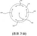
도 1은 종래 기술의 사상에 따르는 종래의 인공 관절의 측면도.1 is a side view of a conventional artificial joint according to the prior art.
도 2는 종래 기술의 다수의 인공 관절을 가진 척추의 측면도.Figure 2 is a side view of a vertebra with multiple artificial joints of the prior art;
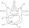
도 3은 인간의 척추골의 상면도.3 is a top view of a human vertebra.
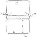
도 4는 척추가 전방 및 후방으로 굽혀질 때 척추골의 움직임을 도시하는 2개의 척추골의 측면도.Figure 4 is a side view of two vertebrae showing the movement of the vertebrae when the vertebrae are bent forward and backward.
도 5A는 척추의 측면 만곡 시 척추골의 움직임을 도시하는 척추골의 상면도.5A is a top view of the vertebra showing the movement of the vertebrae when the vertebrae are flexed sideways.
도 5B는 척추의 측면 만곡 시 척추골의 움직임을 도시하는 2개의 척추골의 측면도.Figure 5B is a side view of two vertebrae showing the movement of the vertebrae when the lateral curvature of the spine.
도 6A는 척추가 회전하는 동안 척추골의 움직임을 도시하는 척추골의 상면도.6A is a top view of the vertebra showing the movement of the vertebrae while the spine is rotating.
도 6B는 척추가 회전하는 동안 척추골의 움직임을 도시하는 2개의 척추골의 측면도.6B is a side view of two vertebrae showing the movement of the vertebrae while the vertebra is rotating.
도 7A 및 도 7B는 굽힘 및 회전 시 도 1의 종래 기술의 인공 관절의 움직임을 도시하는 도면.Figures 7A and 7B illustrate the movement of artificial joints of the prior art of Figure 1 during bending and rotation.
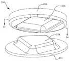
도 8은 본 발명의 인공 디스크의 분해된 투시도.8 is an exploded perspective view of the artificial disc of the present invention.
도 9는 도 8의 선 9-9를 따라 절단한 본 발명의 인공 디스크의 부분적인 절단면도.9 is a partial cutaway view of the artificial disc of the present invention cut along the line 9-9 in Fig.
도 10은 도 9의 인공 디스크의 기저 부분의 측면도.Figure 10 is a side view of the base portion of the artificial disc of Figure 9;
도 11은 본 발명의 인공 디스크의 돌출부의 횡단면도 및 기저 부분의 상면도.11 is a cross-sectional view of the projection of the artificial disk of the present invention and a top view of the base portion.
도 12는 본 발명의 인공 디스크의 돌출부의 횡단면도 및 기저 부분의 상면도.12 is a cross-sectional view of the projecting portion of the artificial disk of the present invention and a top view of the base portion.
도 13A는 도 12의 선 13-13을 따라 절단한 도 8 내지 도 12의 인공 디스크의 횡단면도.Figure 13A is a cross-sectional view of the artificial disc of Figures 8-12 as cut along line 13-13 of Figure 12;
도 13B는 도 13A의 인공 디스크의 그 외의 다른 횡단면도를 도시하며, 돌출부들은 인공 디스크의 상측 부분의 각도를 가변시키기 위해 트로프 내에서 이동된다.Figure 13B shows another cross-sectional view of the artificial disc of Figure 13A, wherein the protrusions are moved in the trough to vary the angle of the upper portion of the artificial disc.
도 13C는 본 발명의 인공 디스크의 그 외의 다른 횡단면도.13C is another cross-sectional view of the artificial disk of the present invention.
도 14A는 도 12의 선 14-14를 따라 절단한 도 8 내지 도 12의 인공 디스크의 횡단면도.14A is a cross-sectional view of the artificial disc of Figs. 8-12, cut along line 14-14 of Fig. 12. Fig.
도 14B는 도 14A의 인공 디스크의 그 외의 다른 횡단면도를 도시하며, 돌출부들은 인공 디스크의 상측 부분의 각도를 가변시키기 위해 트로프 내에서 이동된다.Figure 14B shows another cross-sectional view of the artificial disc of Figure 14A, wherein the protrusions are moved in the trough to vary the angle of the upper portion of the artificial disc.
도 15는 도 12의 선 15-15를 따라 절단한 도 8 내지 도 12의 인공 디스크의 횡단면도.Figure 15 is a cross-sectional view of the artificial disc of Figures 8-12 as cut along line 15-15 of Figure 12;
도 16은 본 발명의 인공 디스크의 돌출부 및 트로프의 확대된 횡단면도.16 is an enlarged cross-sectional view of protrusions and troughs of the artificial disc of the present invention.
도 17은 본 발명의 인공 디스크의 돌출부 및 트로프의 그 외의 다른 상세한 횡단면도.17 is another detailed cross-sectional view of protrusions and troughs of the artificial disk of the present invention.
도 18은 본 발명의 인공 디스크의 상측 부분의 돌출부와 하측 부분의 그 외의 다른 상면도.18 is another top view of the protruding portion and the lower portion of the upper portion of the artificial disc according to the present invention.
도 19는 본 발명의 인공 디스크의 그 외의 다른 상면도.19 is another top view of the artificial disk of the present invention.
도 20은 선 20-20을 따라 절단한 도 19의 인공 디스크의 횡단면도.Figure 20 is a cross-sectional view of the artificial disc of Figure 19 cut along line 20-20.
도 21은 상이한 형태의 돌출부들을 가진 본 발명의 인공 관절의 투시도.Figure 21 is a perspective view of an artificial joint of the present invention having different types of protrusions.
도 22는 도 21의 선 22-22를 따라 절단한 도 21의 인공 관절의 횡단면도.22 is a cross-sectional view of the artificial joint of Fig. 21 cut along line 22-22 in Fig.
도 23은 본 발명의 그 외의 다른 인공 관절의 투시도.23 is a perspective view of another artificial joint of the present invention.
도 24는 도 23의 선 24-24를 따라 절단한 도 23의 인공 관절의 횡단면도.24 is a cross-sectional view of the artificial joint of FIG. 23 taken along line 24-24 of FIG. 23. FIG.
도 25는 본 발명의 그 외의 다른 인공 관절을 도시하는 도면.25 is a view showing another artificial joint according to the present invention;
도 26은 디스크 핵 대체물로 이용되는 본 발명의 인공 관절을 도시하는 도면.26 is a view showing an artificial joint of the present invention used as a disk nuclear substitute;
도 27은 본 발명에 따르는 구속 밴드를 가진 인공 관절을 도시하는 도면.27 is a view showing an artificial joint having a restraining band according to the present invention;
도 28은 본 발명의 그 외의 다른 인공 관절의 횡단면도.28 is a cross-sectional view of another artificial joint according to the present invention;
도 29는 도 28의 관절의 그 외의 다른 횡단면도.29 is another cross-sectional view of the joint of Fig. 28; Fig.
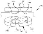
도 30은 도 8-18의 인공 관절과 유사한 인공 관절의 전개된 투시도.30 is an exploded perspective view of an artificial joint similar to the artificial joint of Figs. 8-18;
도 31은 도 30의 관절의 상측 부분의 저면도.31 is a bottom view of the upper portion of the joint of Fig.
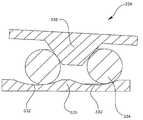
도 32 및 도 33은 도 31의 섹션 라인 32와 33을 따라 절단한 도 30의 관절의 상측 부분의 횡단면도.32 and 33 are cross-sectional views of the upper portion of the joint of Fig. 30 taken along
도 34는 도 30의 상측 부분의 바닥 투시도.34 is a bottom perspective view of the upper part of Fig.
도 35는 도 30의 하측 부분의 상면도.Fig. 35 is a top view of the lower portion of Fig. 30; Fig.
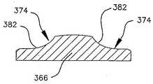
도 36 내지 도 39는 도 35의 섹션 라인 36 내지 39를 따라 절단한 도 30의 관절의 하측 부분의 횡단면도.Figs. 36 to 39 are cross-sectional views of the lower portion of the joint of Fig. 30 taken along
도 40은 도 30의 관절의 하측 부분의 투시도.40 is a perspective view of the lower portion of the joint of Fig. 30;
도 41은 도 8-18 및 도 30-40의 인공 관절과 유사한 인공 관절의 전개된 투시도.41 is an exploded perspective view of the artificial joint similar to the artificial joints of Figs. 8-18 and 30-40; Fig.
도 42는 도 41의 관절의 상측 부분의 바닥 투시도.42 is a bottom perspective view of the upper part of the joint of FIG. 41;
도 43은 도 41의 상측 부분의 저면도.Fig. 43 is a bottom view of the upper portion of Fig. 41; Fig.
도 44 내지 도 47은 도 43의 섹션 라인 44 내지 47을 따라 절단한 도 41의 관절의 상측 부분의 횡단면도.Figures 44 to 47 are cross-sectional views of the upper portion of the joint of Figure 41 cut along
도 48은 도 41의 관절의 하측 부분의 투시도.Figure 48 is a perspective view of the lower portion of the joint of Figure 41;
도 49는 도 41의 관절의 하측 부분의 상면도.Fig. 49 is a top view of the lower portion of the joint of Fig. 41; Fig.
도 50 내지 도 53은 도 49의 섹션 라인 50 내지 53을 따라 절단한 도 41의 관절의 하측 부분의 횡단면도.Figs. 50-53 are cross-sectional views of the lower portion of the joint of Fig. 41 taken along section lines 50-53 of Fig. 49;
도 54는 도 8-18, 30-40 및 41-53의 인공 관절과 유사한 인공 관절의 전개된 투시도.54 is an exploded perspective view of an artificial joint similar to the artificial joints of Figs. 8-18, 30-40 and 41-53;
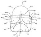
도 55는 도 54의 관절의 상측 부분의 바닥 투시도.55 is a bottom perspective view of the upper part of the joint of Fig. 54; Fig.
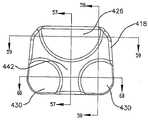
도 56은 도 54의 관절의 상측 부분의 저면도.FIG. 56 is a bottom view of the upper portion of the joint of FIG. 54; FIG.
도 57 내지 도 60은 도 56의 섹션 라인 57 내지 60을 따라 절단한 도 54의 관절의 상측 부분의 횡단면도.Figures 57 to 60 are cross-sectional views of the upper portion of the joint of Figure 54 cut along
도 61은 도 54의 관절의 하측 부분의 투시도.FIG. 61 is a perspective view of the lower portion of the joint of FIG. 54; FIG.
도 62는 도 54의 관절의 하측 부분의 상면도.FIG. 62 is a top view of the lower portion of the joint of FIG. 54; FIG.
도 63 내지 도 66은 도 62의 섹션 라인 63 내지 66을 따라 절단한 도 54의 관절의 하측 부분의 횡단면도.63 to 66 are cross-sectional views of the lower portion of the joint of Fig. 54 taken along
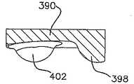
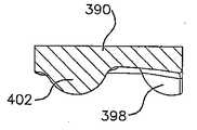
도 67은 리세스를 형성하기 위하여 공구 경로 라인을 따르는 도 54의 관절의 하측 부분의 상면도.67 is a top plan view of the lower portion of the joint of Fig. 54 along the tool path line to form the recess; Fig.
도 68은 도 67의 리세스, 공구에 의해 형성된 표면 및 공구 경로 라인의 투시도.68 is a perspective view of the recess, the surface formed by the tool, and the toolpath line of Fig. 67;
도면들은 첨부된 청구항에 의해 정의된 본 발명의 범위를 제한하지 않으며 도식의 목적으로 제공된다. 도시된 실시예들은 본 발명의 다양한 특징과 목적을 수행하며, 임의의 단일의 도면은 본 발명의 각각의 특징과 장점을 수행하지 못한다. 단일의 도면에서 본 발명의 각각의 요소와 특징을 명확히 도시할 수 없으며, 다수의 도면은 보다 명확함을 위해 본 발명의 다양한 세부사항을 개별적으로 도시하기 위해 제공된다.The drawings are not intended to limit the scope of the invention as defined by the appended claims and are provided for the purpose of illustration. The illustrated embodiments perform various features and objects of the present invention, and any single figure can not perform the respective features and advantages of the present invention. Each element and feature of the invention can not be clearly shown in the single figure, and the plural views are provided for separately showing various details of the invention for the sake of clarity.
본 발명은 종래 기술의 당업자가 본 발명을 실시할 수 있도록 도면 및 도면에 제공된 도면부호에 따라 기술되어 진다. 도면 및 기술 내용은 첨부된 청구항의 범위를 좁히는 의도는 아니며, 본 발명의 다양한 특징들의 실례이다. 몇몇 도면에서, 구조물들을 보다 명확히 도시하기 위하여 통상적으로 서로에 대해 접촉된 인접한 구조물들 사이에 공간이 도시된다.The invention is described herein with reference to the accompanying drawings, which are provided to enable those skilled in the art to practice the invention. The drawings and technical description are not intended to limit the scope of the appended claims, but rather are illustrative of various aspects of the invention. In some figures, a space is shown between adjacent structures that are typically in contact with each other to more clearly illustrate the structures.
일반적으로, 다수의 인공 디스크(artificial disc)들이 현재 이용가능하거나 또는 테스트되어진다. 이러한 인공 디스크들은 자연적인 척추(natural spine)의 안정성을 저하시키는 경향이 있다. 일반적으로 종래 기술의 관절들은 도 1에 도시된 바와 같이 컵 형태의 리셉터클(cup shaped receptacle, 14) 내에 위치된 구형 표면(10) 또는 볼 또는 구형 표면의 상부에 컵 형태의 리셉터클을 포함하는 지지 표면을 포함한다. 이러한 관절은 그 외의 다른 볼 및 소켓 관절과 유사한 방식으로 피벗회전함으로써 이동된다. 일반적으로 리셉터클(18)은 추가적인 척추골, 뼈 및 조직과 같은 관절 위의 체중(body mass)(특정 관절에 의해 지지됨)을 나타낸다. 원(circle, 22)은 도식의 목적으로 기준 지점을 제공하는 관절 위의 체중(body weight)의 일부를 나타낸다. 관절이 굽혀짐으로써 야기될 수 있는 것과 같이(인공 관절을 가진 사람이 굽히는) 볼(10)이 위치(10')로 피벗회전함에 따라, 신체 질량(18)과 기준 지점(22)은 도면부호(18', 22')로 도시된 위치로 이동한다. 위치(22')는 위치(22)보다 낮은 수직 높이에 위치된다.In general, a large number of artificial discs are currently available or tested. These artificial discs tend to reduce the stability of the natural spine. In general, the articulations of the prior art include a
따라서, 관절이 회전 볼(10)에 의해 피벗회전되는 것과 같이 위치(22')로 이동됨에 따라 지점(22)은 일반적으로 하강된다. 관절 위의 신체 질량(18, 22)이 상대적으로 낮은 위치로 이동됨에 따라 관절의 피벗회전은 중력에 의해 수행된다.Thus, the
중력 단독으로 운동을 연속하기 위한 힘을 가하며, 신체 질량(18, 22)은 상대적으로 낮은 위치로 이동된다. 추가 힘이 신체 질량(18, 22)을 재차 이의 원래 위치로 이동시키기 위해 필요하다. 척추(spine)는 각각의 관절 위에서 신체 질량에 가해지는 중력의 힘과 각각의 관절을 둘러싸는 근육 및 그 외의 다른 조직의 긴장에 의해 압축된 상태이다. 이러한 압축력은 모션의 단부 지점들이 최소 에너지 상태를 나타냄에 따라 중립 위치, 즉 중력 포텐셜 에너지와 긴장력이 최소화되는 지점들로부터 종래 기술의 인공 관절을 이격되도록 이동시키는 경향이 있다. Gravity alone exerts a force on the motion to continue, and the
따라서, 도시된 관절은 본질적으로 불안정한 관절이다. 중립 위치로부터 이동될 때, 관절 위의 신체 중량 또는 주위 조직에서 긴장(tension)에 의해 야기되는 관절 상의 압축은 운동을 지속하는 경향이 있다. 종래의 관절은 종간 위치보다 모션의 단부 지점(end point)에서 안정적이며, 이는 관절 상의 압축력이 간절을 중심 지점이기보다는 움직임의 단부 지점으로 이동시키는 경향이 있는 것을 의미한다.Thus, the joints shown are inherently unstable joints. When displaced from a neutral position, compression of the joint caused by tension in the body weight or surrounding tissue on the joint tends to continue the movement. Conventional joints are more stable at the end point of motion than interspecific position, meaning that compressive forces on joints tend to move the snippets to the end points of the motion rather than the center point.
종래의 관절을 둘러싸는 근육 구조물 및 그 외의 다른 조직 구조물들은 중력과 같이 척추에 가해지는 압축력에 대해 중립 위치(관절이 이동되지 않고, 주위 근육과 조직이 안정 길이인 안정 위치)로 관절을 유지시켜야 한다. 드물게, 척추 관절이 정확한 중립 위치에 있을 때, 주위 근육과 조직은 사람이 앉아 있거나 또는 직립으로 서있을 때와 같이 선호되는 위치에 인공 관절을 유지시킬 때 상당량의 스트레스가 가해질 수 있다. 추가적으로, 주위 근육과 조직은 척추가 굽혀진 이후 관절을 중립 위치로 복귀시키기 위하여 상대적으로 격심하게 움직여야 한다. 차례로, 이에 따라 척추의 인접한 관절/구조물과 연결된 조직 및 근육에 손상이 야기될 수 있으며, 이는 척추가 적절히 움직이는 것을 방해하고, 통증을 악화시킨다. 따라서, 현저하게 안정적인 인공 디스크를 가지는 것이 선호되는 것이라는 것을 이해할 수 있다. 관절 위의 신체 질량 및 체중에 가해지는 중력과 같이 척추 상에 작용하는 압축력이 관절을 재차 중립 위치로 보내고 중립 위치로부터 떨어지지 않도록 하는 인공 관절을 가지는 것이 선호된다.Conventional muscle structures and other tissue structures that surround the joints must maintain the joints in a neutral position (ie, a stable position where the joints are not moved and the surrounding muscles and tissues are stable) with respect to the compression force applied to the spine, such as gravity do. Rarely, when the vertebral joint is in the correct neutral position, the surrounding muscles and tissues can be subjected to a significant amount of stress when holding the artificial joint in the preferred position, such as when a person is sitting or standing upright. In addition, the surrounding muscles and tissues must move relatively heavily to return the joint to its neutral position after the vertebra is bent. In turn, this can cause damage to the tissues and muscles associated with adjacent joints / structures of the vertebrae, which interfere with proper movement of the vertebrae and exacerbate the pain. Thus, it is understood that having a significantly stable artificial disk is preferred. It is preferred that the compressive forces acting on the vertebrae, such as gravity on the body mass and body weight on the joint, have artificial joints that allow the joints to travel back to the neutral position and not fall off from the neutral position.
도 2는 도 1의 2개 또는 이보다 많은 인공 디스크를 가진 사람의 척추의 실례를 도시한다. 복수의 척추골(30a-30g)과 건강한 척추 디스크(34a, 34b, 34e, 34f)가 도시된다. 척추골(30c, 30d)들 사이 그리고 척추골(30d, 30e)들 사이의 자연적인 척추 디스크는 도 1에 따라 언급된 바와 같이 볼 및 트로프 디스크(trough disc)를 포함하는 종래의 인공 디스크(38c, 38d)에 의해 교체되어진다. 언급된 바와 같이, 볼과 트로프 디스크는 중력과 같은 압축력이 움직임을 강화시키고 관절을 중립 위치로 복귀시키는 대신에 중립 위치로부터 관절을 멀리 가압하는 고유의 불안정성을 가진다.Figure 2 shows an example of a spine of a person with two or more artificial discs of Figure 1; A plurality of
도면부호(38c, 38d)로 도시된 바와 같이 2개 또는 이보다 많은 인공 디스크에 따라 상기의 문제점은 더욱더 달성하기가 어렵다. 하나의 인공 디스크(38d)가 중립 위치로부터 이동될 때, 중력, 척추를 둘러싸는 신체 조직의 균형이 잡히지 않은 긴장, 등등으로 인해 제 2의 인공 디스크(38c)는 (38d)의 상반된 방향으로 피벗회전한다. 종래의 인공 디스크를 가진 환자는 인공 디스크가 척추를 굽혀지거나 또는 접혀 진 위치로 가압하는 경향이 있기 때문에 적합한 정렬 상태 또는 자세로 척추를 유지시킬 수 없다. 따라서, 척추는 적합한 위치로 척추를 유지시키기 위한 신체의 불안정성 및 인공 디스크(38c, 38d)의 불안정성으로 인해 척추 측만증 또는 척추 만곡증이 야기되거나 또는 신체에 대해 적합한 방향으로 척추를 유지시키기 위하여 상당한 스트레스가 근육과 결합 조직에 제공된다. 시간이 지난 뒤, 인공 디스크로 인해 척추의 만곡(bending) 또는 접힘(collapsing)은 척추와 연관된 조직을 악화시킨다. 따라서, 인공 디스크는 고유의 안정성(natural stability)을 저하시키며, 인공 관절의 오랜 기간 동안의 성과를 감소시키고, 교체되는 디스크의 개수가 증가됨에 따라 점차 감소된다. 사실상, 인공 관절은 건강한 척추 부분의 파괴를 가속화시킬 수 있다.The above problem is more difficult to achieve depending on two or more artificial disks as shown by
종래의 단일의 인공 디스크를 가진 척추는 하나 또는 이보다 많은 인접한 자연적인 디스크의 바람직하지 못하고 과도한 만곡을 야기하며, 이에 따라 도 2에 도시된 형태와 유사한 척추 형태로 형성된다. 인공 디스크에 인접한 자연적인 디스크의 바람직하지 못한 만곡으로 인해 자연적인 관절의 퇴행이 야기되거나 또는 가속화되며, 추가 디스크를 교체할 필요성이 대두될 수 있다.A vertebra with a conventional single artificial disc results in undesirable and excessive curvature of one or more adjacent natural discs and thus is formed in a spinal form similar to that shown in Fig. The undesirable curvature of the natural disk adjacent to the artificial disk can cause natural joint regressions or accelerate and the need to replace the additional disk may arise.
인공 디스크의 추가적인 문제점은 자연적인 모션의 보존(preservation)과 복원(restoration)에 있다. 인공 관절을 이용하여 자연적인 모션을 제공하는 것은 사람에게 편안한 움직임을 제공하는 것과 같은 다수의 요인으로 인해 중요하다. 아마도, 인공 관절이 주변 조직에 대해 가지는 효과가 보다 중요할 수도 있다. 이러한 모션이 부자연스럽다면, 주변 근육, 힘줄, 등등과 같이 관절을 이동시키기 위한 조직이 관절에 의해 부정적인 영향을 받는다. 주변 조직은 관절을 적절히 조절할 수 없거나 또는 인공 관절의 가변 움직임으로 인해 점차적으로 퇴화된다. 따라서, 자 연스러운 움직임에 따른 인공 관절을 제공하는 것은 인공 관절의 오랜 기간의 성과에 대한 상당한 효과를 가질 수 있다.An additional problem with artificial discs is the preservation and restoration of natural motion. Providing natural motion using an artificial joint is important because of a number of factors, such as providing comfortable movement to a person. Perhaps the effect that the artificial joint has on surrounding tissues may be more important. If these motions are unnatural, the tissues for moving the joints, such as the surrounding muscles, tendons, etc., are negatively affected by the joints. The surrounding tissue can not adequately regulate the joint or is gradually degraded due to the variable movement of the artificial joint. Thus, providing artificial joints due to natural movement can have a significant effect on long-term performance of artificial joints.
인공 무릎 또는 힙과 같은 다수의 인공 관절은 소켓 타입의 관절 내의 힌지 또는 볼과 같이 상대적으로 단순한 움직임을 수행하는 상대적으로 단순한 관절이다. 그러나, 척추골 및 자연적인 디스크(natural disc)는 복합적인 움직임을 수행한다. 자연적인 디스크는 매트리스와 같은 소프트 패드(soft pad)이다. 자연적인 디스크로 인해 척추골의 움직임이 가능하고 유지되며, 척추골은 척추의 정상적인 움직임을 수행하기 위하여 수평, 수직 및 회전 움직임의 조합에 따라 디스크를 가로질러 이동될 수 있다.Many artificial joints, such as artificial knees or heaps, are relatively simple joints that perform relatively simple movements, such as hinges or balls within socket-type joints. However, vertebrae and natural discs perform complex movements. Natural discs are soft pads such as mattresses. The natural discs enable and maintain the movement of the vertebrae, and the vertebrae can be moved across the disc according to a combination of horizontal, vertical and rotational movements to perform the normal movement of the vertebrae.
도 1 및 도 2에 도시된 바와 같이 종래의 인공 디스크는 척추의 자연스러운 움직임에 적합하지 못하다. 다수의 종래의 인공 디스크로 인해 척추골은 피벗 회전 움직임으로 이동될 수 있으며, 대칭의 전방 및 후방을 향하는 움직임을 수행한다. 언급된 바와 같이, 인공 관절과 자연적인 관절 사이의 움직임의 차이로 인해 주변 근육과 조직에 대해 바람직하지 못한 효과가 야기될 수 있다. 근육과 조직은 관절을 자연스러운 움직임으로 움직이는데 익숙하고 적응되며, 부자연스러운 움직임을 수행하는 인공 관절을 적합하게 조절할 수 없거나 퇴화된다. 인공 관절을 적절히 움직이고 조절하는데 있어서 이러한 퇴화와 불능은 종래의 인공 관절의 불안정성을 가속화시키며, 도 1 및 도 2에 따라 언급된 관절의 문제점을 야기하거나 또는 가속화시킬 수 있다.As shown in Figures 1 and 2, conventional artificial discs are not suitable for natural movement of the spine. Due to the number of conventional artificial discs, the vertebrae can be moved in a pivoting motion and perform forward and backward movement of the symmetry. As noted, the difference in motion between the artificial joint and the natural joint may cause undesirable effects on the surrounding muscles and tissues. Muscles and tissues are accustomed and adapted to move joints in natural motion, and the artificial joints that perform unnatural movements can not be adequately controlled or degenerated. This degeneration and disability in properly moving and adjusting the artificial joints accelerates the instability of conventional artificial joints and can cause or accelerate the problems of the joints referred to in FIGS. 1 and 2.
따라서, 자연스러움 움직임을 제공하고 현저하게 안정적인 관절 내에 인공 디스크를 제공하는 것이 선호된다. 이러한 목적을 구현함으로써, 중립 위치에서 신체에 대한 지지부를 제공하기 위하여 관절의 손상 및 관절을 조절하기 위한 주변 조직의 퇴화와 같은 신체에 대한 부정적인 영향을 최소화하는 인공 디스크 및 관절이 제공된다.Thus, it is preferred to provide artificial discs within the joints that provide natural motion and are significantly stable. By implementing this object, artificial discs and joints are provided that minimize the negative effects on the body, such as damage to the joints and degeneration of the surrounding tissue to control the joints, in order to provide a support for the body in the neutral position.
경추(목)의 움직임에 대한 연구는 척추의 운동학적 움직임이 복합적이고 비대칭의 움직임이라는 것을 보여준다. 척추의 움직임은 척추골 몸통들의 병진 움직임과 회전 움직임의 결합으로 관찰되어 진다. 여기서, 척추의 움직임은 디스크의 하부에서 척추골 몸통의 해당 부분에 대해 척추 디스크 위의 척추골 몸통의 일부분의 움직임을 기술함으로써 설명된다. 만곡/신장은 병진운동의 동일한 방향으로 척추골 몸통의 회전운동과 조합하여 전방으로 또는 후방으로 척추골 몸통의 병진운동을 수반한다. 일반적으로 회전은 몇몇의 리프팅 및 몇몇의 측면 틸팅과 조합하여 척추골 몸통의 중심 뒤의 지점 주위에서 척추골 몸통의 회전을 수반하며, 척추골 몸통은 좌회전, 등등 동안 다소 좌측으로 틸팅된다. 측면 굽힘은 회전, 만곡/신장 및 측면 틸팅을 조합하여 다수의 척추 관절의 협력에 의해 수행된다. 자연적인 척추의 움직임은 Panjabi씨의 Spine. 2001 Dec 15;26(24):2692-700; Ishii씨의 Spine. 2006 Jan 15;31(2):155-60; Ishii 씨의 Spine. 2004 Dec 15;29(24):2826-31 및 Ishii씨의 Spine. 2004 Apr l;29(7):E139-44에 기술된다.Studies of the movement of the cervical vertebrae indicate that the kinematic movements of the vertebrae are complex and asymmetric movements. The movement of the vertebrae is observed by the combination of translational and rotational movements of the vertebral bodies. Here, the movement of the vertebrae is described by describing the movement of a portion of the vertebral body above the vertebral disk relative to the corresponding portion of the vertebral body at the lower portion of the disc. The curvature / kidney involves translational movement of the vertebral body forward or backwards in combination with rotational movement of the vertebral body in the same direction of translational motion. Rotation generally involves rotation of the vertebra body around a point behind the center of the vertebral body in combination with some lifting and some lateral tilting, while the vertebral body is tilted somewhat to the left during the left turn, etc. Side bending is accomplished by the cooperation of multiple spinal joints in combination with rotation, curvature / extension and lateral tilting. The movement of the natural spine is Panjabi's Spine. 2001
도 3은 척추골(50)의 상면도를 도시한다. 척추골은 주변 조직, 척추의 통로, 등등의 부착을 위한 다양한 구조물을 포함한다. 본 발명이 척추 디스크 및 인공 디스크를 제공하는 것과 연관되기 때문에, 일반적으로 척추골의 도면과 기술 내용은 척추 디스크로 연결되는 둥근 전방 영역(50a)과 척추골 몸통으로 제한된다. 따라서, 본 출원서는 간략함을 위해 둥글거나 또는 원통형 섹션과 같은 척추골 몸통을 도시한다. 척추골의 디스크 영역의 후부(후방)는 지점(54)으로 도시되며, 전면(전방)은 도면부호(58)로 도시된다. 일반적으로 이해되는 바와 같이, 후관절(facet joint, 52)은 자연적인 척추의 움직임을 조절하는데 도움이 된다. 이러한 지점들은 척추골의 움직임을 설명하는 것으로 언급된다.Fig. 3 shows a top view of the
도 4는 전방 및 후방을 향하여 만곡되는 경추(cervical vertebra)의 일반적인 움직임을 도시하는 2개의 척추골의 측면도를 도시한다. 척추골(50)의 후부(54)와 전면(58)는 척추골(46)에 대해 상이하게 이동되는 것으로 관찰된다. 척추골(50)의 전면(58)는 척추골(50)의 후부(54)에 비해 보다 많이 수직 방향으로 이동된다. 또한, 척추골(50)의 움직임은 축추골(46)에 대해 상당한 미끄럼 움직임을 수반한다. 척추골 사이의 디스크(62)는 상당히 일정하며(conforming), 척추골(50)의 전방 및 후방 움직임과 같이 척추골을 움직일 수 있도록 형태가 가변된다. 본 발명은 경추 디스크를 교체하기 위해 관절에 관해 인공 관절을 언급할지라도, 선호되는 범위의 움직임을 구현하고 움직임을 조절하기 위해 돌출부 및 리세스의 형태를 변형시키고 인공 관절의 크기를 변형시키는 것뿐만 아니라 그 외의 다른 척추 디스크를 교체하기 위해 이용될 수 있는 것으로 이해하여야 한다.Figure 4 shows a side view of the two vertebrae showing the general movement of the cervical vertebra in anterior and posterior directions. The
도 5A는 측면 만곡(lateral bending) 동안 척추골의 다양한 지점의 수평 움직임을 도시하는, 척추골(50)의 상면도이다. 척추골(50)의 후부(54)는 측면 만곡 동안 실질적으로 동일한 위치에 유지된다. 척추골(50)의 중심(66)고 전면(58)는 척 추골의 후부(54)에 대해 피벗회전하고, 화살표(70, 74)로 도시된 아치형 움직임으로 이동한다. 또한, 척추골(50)의 좌측면(78)과 우측면(82)은 화살표(86, 90)로 도시된 방향으로 척추골의 후부(54) 주위에서 피벗회전하는 것과 같이 아치형 움직임으로 이동한다.5A is a top view of the
도 5B는 측면 만곡 동안 척추골의 다양한 지점의 수직 움직임을 도시하는 척추골(50)의 정면도이다. 척추골(46)과 디스크(62)는 척추골(46)에 대해 척추골(50)의 움직임을 나타내기 위해 도시되어진다. 측면 만곡 시, 척추골(50)의 전면(58)는 화살표(94)로 도시된 바와 같이 척추골(46)에 대해 수평방향으로 이동된다. 척추골(50)의 좌측면(78)과 우측면(50)은 화살표(98, 102)로 도시된 바와 같이 수평 방향뿐만 아니라 수직방향으로 이동된다.Figure 5B is a front view of the
도 5A 및 도 5B에 도시된 바와 같이, 척추골(50)의 측면 만곡은 복합적인 움직임이다. 척추골(50)은 측면으로 트위스트되고, 미끄러진다. 척추골(50)은 디스크(62)를 가로질러 미끄러지며, 척추골(50)의 후부 지점(54) 주위에서 피벗회전한다. 척추골(50)의 좌측면(78) 또는 우측면(82)이 측면으로 이동됨에 따라 이는 수직 방향으로 이동되고, 척추골(50)은 척추골(46)에 대해 트위스트된다. 상기 언급된 바와 같이, 일반적으로 측면 만곡은 선호되는 움직임을 구현하기 위하여 다수의 척추 관절의 협응 움직임(coordinated movement)을 수반한다. 도 5A 및 도 5B는 척추의 자연스러운 측면 만곡을 허용하기 위하여 단일의 척추 관절의 선호되는 움직임을 도시한다.As shown in FIGS. 5A and 5B, the side curvature of the
도 6A는 척추골(50)이 회전하는 동안 척추골의 다양한 지점의 수평 움직임을 도시하는 척추골(50)의 상면도이다. 척추골(50)은 척추골의 중심 뒤에서 지점(66) 에 대해 다소 회전한다. 이와 같이, 전면 지점(58), 후부 지점(54) 및 측면 지점(78, 82)은 도시된 바와 같이 화살표(56, 60, 80, 84)에 따라 이동한다. 도 6B는 회전하는 동안 척추골(50)의 수평 움직임을 도시하는, 척추골(46)과 디스크(62)뿐만 아니라 척추골(50)의 정면도이다. 척추골(50)은 화살표(96, 100, 104)로 도시된 바와 같이 회전의 측면을 향하여 틸팅할 뿐만 아니라(즉 좌회전 동안 좌측으로 틸팅) 수직 틸팅도 한다.6A is a top view of the
도 1에 도시된 바와 같이, 종래의 인공 디스크는 볼 및 소켓 타입 형상을 포함하거나 또는 2개의 소켓들 사이에 반구형 디스크, 등등을 포함한다. 도 1의 종래의 인공 척추골은 도 3 내지 도 6에 도시된 바와 같이 자연적인 척추골과 유사한 방식으로 이동되지 않는다. 도 7A는 굽힘/신장 및 측면 만곡에 대한 종래의 인공 디스크의 움직임을 도시한다. 상측 척추골 표면(10)의 후부(106) 및 전면(110)는 화살표(114, 118)에 따라 이동한다. 이러한 움직임은 도 4에 도시된 자연적인 척추의 굽힘 움직임(flexing movement) 및 측면 만곡 움직임(lateral bending movement)과 상당이 상이하다. 인공 디스크의 측면 만곡 움직임은 굽힘 움직임과 유사한 반면, 자연적인 척추는 회전 및 굽힘 움직임의 조합에 따라 횡방향으로 굽혀진다. 신체 내에 형성된 압축력은(힘줄과 근육의 긴장 및 신체의 중량, 등등과 같은) 종래의 인공 디스크로 가해지는 압축력에 따라 종래의 디스크가 중립 위치로부터 이격되는 상당히 굽혀지거나 또는 만곡된 위치로 이동시키는 중립 굽힘 위치로 자연적인 척추골을 복귀시키는 경향이 있다.As shown in Figure 1, conventional artificial discs include ball and socket type shapes or include hemispherical discs, etc. between two sockets. The conventional artificial vertebra of Fig. 1 is not moved in a manner similar to a natural vertebra, as shown in Figs. 3-6. Figure 7A shows the movement of a conventional artificial disc with respect to bending / stretching and side curvature. The
도 7B는 관절의 회전 움직임을 도시하는 도 1의 종래의 인공 디스크의 상면도이다. 상측 척추골 표면(10)은 화살표(126)로 도시된 바와 같이 중심(122) 주위에서 피벗회전한다. 볼과 소켓 타입의 인공 디스크는 디스크의 수직 움직임 없이 피벗 회전하고, 디스크의 중심 주위에서 피벗회전한다. 도 5 및 도 6에 도시된 바와 같이, 자연적인 척추골은 종래의 인공 디스크가 적절히 반복하지 못하는 몇몇의 리프팅 및 틸팅의 조합에 따라 디스크의 후방을 향하여 한 지점 주위에서 피벗회전한다. 신체 내에 형성되는 압축력(중략 및 근육 긴장, 등등과 같은)은 자연적인 척추골을 중립 피벗회전 위치로 편향시키는 반면 종래의 인공 척추골은 중립 위치로 편향되지 못한다.7B is a top view of the conventional artificial disc of Fig. 1 showing the rotational movement of the joint. The
따라서, 종래의 인공 디스크로 인해 관절 내에서 자연적인 척추의 움직임을 재현하지 못하며, 고유의 안정성이 결여된다(척추에 작용하는 자연스러운 압축력에 의해 중립 위치로 편향되지 못하거나 또는 자체적으로 중심에 위치되지 못할 수 있음). 이러한 요인으로 인해, 특정의 척추 관절을 움직이는 근육, 결합 조직 및 지지 관절 상에 추가 스트레스가 가해지고 부자연스러운 움직임이 야기된다. 따라서, 종래의 인공 관절은 척추의 장애에 기여할 수 있다.Thus, conventional artificial discs do not reproduce natural spinal motion within the joints and lack inherent stability (due to the natural compression force acting on the spine, they can not be biased to a neutral position, You can not). These factors cause additional stress on the muscles, connective tissue, and supporting articulation that move a particular spinal joint and result in unnatural movements. Thus, conventional artificial joints can contribute to the disability of the vertebrae.
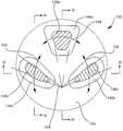
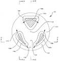
도 8에 관하여, 본 발명에 따르는 인공 관절(130)의 분해된 투시도가 도시된다. 상기 관절(130)은 복수의 리세스(146a, 146b, 146c)(일반적으로 146)를 가진 하측 부분(142)과 복수의 돌출부(138a, 138b, 138c)(일반적으로 138)를 가진 상측 부분(134)을 포함한다. 상기 돌출부(138)는 인공 관절이 척추 내에서 디스크를 교체하기 위하여 조립될 때 리세스(146) 내에 수용된다. 리세스(146)는 돌출부(138) 가 접촉하는 표면이 형성되며, 돌출부의 가능한 이동 범위를 형성하고, 이에 따라 하측 표면(142)에 대한 상측 표면(134)의 움직임이 구현된다. 리세스의 표면과 돌출부의 표면 사이의 상호 작용에 따라 자연적인 척추의 움직임을 밀접하게 모사하는 인공 관절(130)의 조절된 움직임이 제공된다.8, an exploded perspective view of an artificial joint 130 according to the present invention is shown. The joint 130 includes an
본 발명을 설명하고, 하기 도면에서 본 발명을 도시하는데 있어서, 리세스와 돌출부는 종종 구획된 영역(bounded area)으로 언급된다. 하기 기술내용과 도면에 따라서, 돌출부와 리세스는 종종 평활하게 윤곽이 형성되며, 주변 재료로부터 점진적으로 전이된다. 따라서, 돌출부 또는 리세스에 대해 날카롭게 형성된 변부가 제공되지 못할 수 있다. 예를 들어, 리세스의 형성된 바운더리는 돌출부가 이동되는 영역 또는 인공 관절의 예상된 이용 동안 돌출부와 접촉하는 영역을 나타낼 수 있다. 인공 관절의 몇몇 형상에 있어서, 돌출부 또는 리세스는 리테이닝 벽(retaining wall)이 인공 관절의 움직임의 범위에 대해 양의 제한(positive limit)을 제공하기 위해 이용될 때와 같이 보다 날카롭게 형성된 변부를 가질 수 있다. 그 외의 다른 형상에 있어서, 리세스는 한정되지 않거나 또는 개별 변부를 가지지 않을 수 있으며, 하측 표면에 대해 상측 표면의 움직임을 제한하기 위한 핀과 같은 그 외의 다른 구조물을 가질 수 있다. 따라서, 용어 리세스는 돌출부를 형성하는 일반적인 영역 또는 부분을 형성하는 것으로 폭 넓게 이용되며, 마주보는 측벽들 또는 신장 특성을 가진 구조물로 제한하기 위함은 아니다.In describing the present invention and illustrating the invention in the following figures, recesses and protrusions are often referred to as bounded areas. According to the following description and drawings, protrusions and recesses are often smoothly outlined and gradually transitioned from peripheral material. Therefore, the sharpened portion may not be provided for the protrusion or the recess. For example, the formed boundary of the recess may indicate an area in which the protrusion is moved or an area in contact with the protrusion during the expected use of the artificial joint. In some configurations of the artificial joint, the protrusions or recesses may have a more sharply defined side, such as when the retaining wall is used to provide a positive limit for the range of movement of the artificial joint. Lt; / RTI > In other configurations, the recess may be unrestricted or may not have individual sides, and may have other structures, such as pins, to limit movement of the upper surface relative to the lower surface. Thus, the term recess is used broadly to form a general region or portion that forms a protrusion, and is not intended to be limited to structures having opposing sidewalls or elongation properties.
하기 도면과 기술 내용은 인공 디스크(130)에 의해 허여되는 움직임의 범위 및 타입과 돌출부(138) 및 리세스(146)의 프로파일을 보다 잘 기술한다. 도면과 기 술 내용에 따라서, 리세스(146)는 돌출부(138)를 전체적으로 수용하기 위하여 가파르게 경사진 수직 변부를 필수적으로 가질 필요가 없지만 하측 표면(142)의 인접한 표면으로부터의 점진적인 전이부(transition)가 형성될 수 있다. 용어 리세스는 돌출부(138)에 의해 접촉되는 표면들을 기술하기 위해 이용되며, 상기 표면들을 가로질러 인공 디스크(130)의 움직임을 허용하기 위하여 돌출부가 미끄러진다.The following figures and technical description better describe the range and type of motion provided by the
하측 부분(142)의 하측 표면(도시되지 않음)(144)과 상측 부분(134)의 상측 표면(132)은 인공 관절을 형성하기 위하여 뼈로 부착되도록 구성된다. 따라서, 부착 표면(132, 144)은 종래 기술에 공지된 바와 같이, 뼈, 등등으로의 결합을 유도하기 위하여 스파이크, 다공성 구조물 및 케미컬을 가질 수 있다. 이러한 표면들은 모든 도면에서 상세하게 나타나지는 않지만 필요 시 본 명세서에 공개된 모든 인공 관절의 일부분인 것으로 이해되어 진다. 추가적으로, 상측 부분(134) 및/또는 하측 부분(142)의 기저부는 인공 디스크(130)가 평평하게 형성되지 않으며 웨지 형태로 형성되도록 두께가 테이퍼 구성될 수 있다. 웨지 형태의 인공 디스크(wedge shaped artificial disc)는 환자의 척추 내에 형성되는 척추 전만증, 척추 후만증, 척추 측만증 또는 그 외의 다른 상태를 어드레스하는데(address) 유용하다. 웨지 형태의 인공 디스크를 제조하기 위해 테이퍼 구성된 두께를 가진 인공 관절은 본 명세서에 공개된 모든 인공 관절의 일부분을 이용하는 것으로 이해되어 진다. 이러한 부착 구조물 또는 테이퍼구성된 두께는 모든 상황에서 요구되지 않을 수 있거나 또는 특히 인공 관절이 핵 치환(nuclear replacement)을 위해 크기가 형성되는 상황에서 다양한 크기 또는 형상으로 구성될 수 있다.The lower surface (not shown) 144 of the
도 9는 돌출부(138)와 리세스(146)의 가능한 형상을 도시하는 관절(130)의 부분적으로 절단된 상면도이다. 돌출부(138)의 횡단면뿐만 아니라 하측 부분(142)과 리세스(146)가 도시된다. 상측 부분(134)의 나머지 부분은 명확함을 위해 생략된다(본 명세서에 언급된 바와 같이, 돌출부가 상측 부분으로부터 하측 부분의 리세스 내부로 하향 연장됨에 따라 형상은 뒤집혀지며, 이에 따라 돌출부는 하측 부분으로부터 상측 부분 내의 리셉터클로 상향 연장되는 동시에 본 명세서에 기술된 안정성이 유지된다.).Figure 9 is a partially cutaway top view of the joint 130 showing the possible shape of the
도 9 및 하기 도면들은 도 8의 선 9-9를 따라 절단된 것이며, 인공 관절의 형상 및 돌출부와 리세스의 형태와 방향을 나타내기 위해 이용된다.9 and the following figures are cut along the line 9-9 of FIG. 8 and are used to indicate the shape of the artificial joint and the shape and orientation of the protrusion and recess.
돌출부(138)는 상측 부분(134) 상의 반구형 돌출부와 같이 형성되며, 리세스(146)와 구별을 위해 크로스해칭으로 도시된다. 리세스(146)는 하측 부분(142)에 형성된다. 리세스는 반구형 리세스와 같이 형성될 수 있거나 또는 타원형, 신장(kidney) 또는 계란 형태의 리세스와 같이 형성될 수 있다. 예를 들어, 전면 리세스(146a)는 측면을 따라 연장된 긴 축을 가진 타원형 리세스와 같이 형성될 수 있다. 측면 리세스(146b, 146c)는 하측 층(142)의 인접한 변부에 대해 다소 평행하게 연장된 긴 축을 가진 타원형 리세스와 같이 형성될 수 있다. 형태를 고려하지 않고, 바람직하게, 리세스는 돌출부의 인접한 부분보다 좌우로 보다 크며, 이에 따라 돌출부는 리세스의 측벽들을 연결하기에 앞서(수직보다 다소 경사진) 병진 운동이 제공된다.The
하기 도면에 보다 상세히 도시된 바와 같이, 일반적으로 리셉터클은 인공 관 절의 움직임을 조절하도록 윤곽이 형성된다. 일반적으로, 리셉터클(146)의 바닥 부분은 몇몇의 병진운동을 허용하도록 상대적으로 평평하게 형성되며, 리셉터클의 내부를 향하는 측면들은 이의 특정 측면이 하측 부분(142)의 중심을 향하여 미끄러짐에 따라 상측 부분(134)을 리프팅하기 위해 증가적으로 경사진다. 리셉터클(146)의 외측 부분은 리셉터클의 하측 부분의 방향으로 단순히 연속될 수 있거나 또는 인공 관절(130)의 움직임을 제한하는 리테이닝 벽 또는 가파르게 경사진 표면을 포함할 수 있다. 돌출부(138)는 자연적인 척추의 움직임과 상반되는 것과 같이 하측 부분(142)의 중심으로부터 이격되도록 이동되는 상측 부분(134)의 측면을 리프팅하기 위하여 리셉터클(146)의 경사진 외측 부분을 상승시킬 필요는 없다.As shown in more detail in the following figures, the receptacle is generally contoured to regulate the movement of the artificial tubule. In general, the bottom portion of the
추가적으로, 리세스(146)는 관절의 움직임을 조절하는데 도움이 되도록 다양한 각도로 배향될 수 있다. 전면 리세스(146a)는 완벽히 수직으로 방향설정되기보다는 다소 전방을 향하여 방향설정될 수 있다. 측면 리세스(146b, 146c)는 횡방향 측면 외부로 그리고 다소 후방을 향하여 방향설정될 수 있다.Additionally, the
도 10은 도 9의 하측 부분의 측면도이다. 이는 전면 리세스(146a)가 완벽히 수직이기보다는 전방을 향하는 방향으로 방향설정되고, 측면 리세스(146b, 146c)(도시되지 않음)가 완벽히 수직 방향으로부터 외측을 향하여 그리고 후방을 향하여 틸팅되도록 방향설정되는 방식을 보다 명확히 도시한다. 리세스(146)의 방향설정은 돌출부와 상측 부분의 움직임을 조절하는데 도움이 되며, 이에 따라 인공 디스크(130)의 움직임이 조절된다. 인공 디스크(130)의 움직임은 하기 도면과 기술 내용에서 보다 상세히 언급되어진다.10 is a side view of the lower portion of Fig. This ensures that the
도 11은 돌출부(138)와 리세스(146)의 대안의 형상을 도시하는, 인공 디스크(130)의 부분적으로 절단된 상면도이다. 돌출부(138)는 후부 지점(150)으로부터 연장된 점선으로 도시된 바와 같이 후부 지점(150)과 일반적으로 반경방향으로 정렬된 측면을 가지도록 형성된다. 유사하게, 일반적으로 리셉터클(146)의 형태는 반경방향 선을 따른다. 이러한 반경방향 정렬에 따라 디스크는 후부 지점(150) 주위에서 회전하며, 상기 언급된 바와 같이 자연적인 척추의 움직임을 모사한다.11 is a partially cutaway top view of an
디스크가 회전함에 따라, 전면 돌출부(138a)는 화살표(148)로 도시된 바와 같이 횡방향으로 이동하며, 측면 돌출부(138b, 138c)는 화살표(152, 156)로 도시된 바와 같이 이동한다. 상측 부분(134)이 우측으로 회전함에 따라, 좌측 측면 돌출부(138c)는 리세스의 측면과 연결되도록 수직 방향으로 상승되고, 이에 따라 회전하는 동안 자연적인 척추의 틸팅이 모사된다. 상측 표면(134)이 하측 표면(142)에 대해 좌측으로 회전할 때, 우측 측면 돌출부(138b)는 유사한 방식으로 상승된다. 이러한 움직임은 도 13 내지 도 15에 도시된다.As the disc rotates, the
도 12는 돌출부(138)와 리세스(146)의 대안의 형상을 도시하는, 인공 디스크(130)의 부분적인 단면도를 도시한다. 측면 돌출부(138b, 138c)와 측면 리세스(146b, 146c)는 다소 만곡되도록 형성된다. 이러한 커브로 인해 상측 부분(134)은 하측 부분(142)에 대해 지점(154) 주위에서 회전한다. 측면 돌출부(138b, 138c)와 측면 리세스(146b, 146c)의 만곡된 표면으로 인해 사전정해진 움직임으로 디스크(130)의 회전 움직임이 구속되는데 도움이 된다.Figure 12 shows a partial cross-sectional view of an
지점(154)은 후부 부분(지점(158)로 도시됨)의 다소 전방에 위치되지만 디스 크의 중심(162) 뒷면에 위치된다. 디스크(130)의 상측 부분(134)이 회전함에 따라 전면 돌출부(138a)는 화살표(166)를 따라 이동하고, 측면 돌출부는 화살표(170, 174)를 따라 이동한다. 리세스(146c)의 형태로 인해 상측 부분(134)이 우측으로 피벗회전할 때 좌측 측면 돌출부(138c)는 수직 상승되고, 리세스(146b)의 형태로 인해 상측 부분의 좌측으로 피벗회전할 때 우측 측면 돌출부(138b)는 상승하며, 회전 시 자연적인 척추의 틸팅이 모사된다.
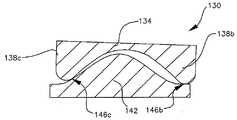
도 13A는 선(13-13)을 따라 도 8 내지 도 12의 인공 디스크(130)의 횡단면도를 도시한다(도 12에 도시된 바와 같이). 상기 횡단면은 도 8에 포함되는 것과 같이 인공 디스크(130)의 상측 부분(134)과 하측 부분(142)을 도시하며, 섹션 라인은 도시된 섹션을 나타내는데 있어서 명확함을 위해 도 12에 도시된다. 돌출부(138b, 138c)는 리세스(146b, 146c)의 표면을 가로질러 평활한 슬라이딩 움직임(회전 및 병진운동)을 허용하기 위해 둥근 하측 표면을 가지는 것으로 관찰될 수 있다. 또한, 리세스(146b, 146c)는 움직임의 선호되는 범위를 따라 평활하고 연속적인 움직임을 제공하기 위해 평활하게(smoothly) 형성된다. 정지 위치에서, 돌출부(138b, 138c)의 바닥은 리세스(146b, 146c)의 일반적으로 평평한 바닥 상에 배열된다. 따라서, 관절은 상당히 안정적이며, 이는 정기 상태에서 고정되는 관절을 위한 추가 작업이 요구되지 않기 때문이다. 주변 조직의 긴장 및 신체의 체중과 같이 관절에 가해지는 압축력은 정지 상태로 관절을 편향시키는 경향이 있다. 관절의 정지 상태는 현저하게 안정적이며(효과적으로 최소화), 자연적인 척추의 중립 위치(neutral position)에 해당한다.Figure 13A shows a cross-sectional view of the
상측 부분(134)이 하측 부분(142)에 대해 우측으로 미끄러질 때(자연적인 척추에서 발생되는 것과 같이), 좌측 돌출부(138c)는 리세스(146c)의 표면을 따라 상향 이동됨에 따라 상승된다. 우측 돌출부(138b)는 리세스(146b)의 일반적으로 평평한 바닥을 가로질러 수평 방향으로 이동되며, 이에 따라 자연적인 척추와 일치되도록 상측 부분(134)이 틸팅되고, 인공 디스크의 네트 팽창(net expansion)이 야기된다. 상측 표면(134)의 좌측 움직임에 따라 우측 돌출부(138b)는 리세스(146b)의 측벽을 따라 수직 방향으로 상승되는 반면, 좌측 돌출부(138c)가 일반적으로 수평방향으로 미끄러짐에 따라 상측 부분(134)는 좌측을 틸팅되고, 인공 디스크의 네트 팽창이 야기된다. 리세스(146)의 측벽과 돌출부(138)의 곡률 및 행정(travel)을 일치시킴으로써 상측 표면(134)은 자연적인 척추에서 야기되는 행정과 밀접하게 유사할 수 있다. 따라서, 자연적인 척추를 둘러싸는 조직 내의 긴장 및 인공 관절 위의 신체의 체중과 같이 척추 상에 가해지는 압축력에 따라 이러한 힘이 인공 관절을 압축하기 때문에 인공 관절이 중립 위치로 재차 가압된다. 따라서, 인공 관절(130)은 본질적으로 안정적이며, 이는 압축력이 상측 부분(134)을 이의 원래 중립 위치로 복귀시키는 경향이 있기 때문이다. 따라서, 근육과 결합 조직에 추기 피로가 야기되지 않으며, 관절의 안정성이 증가된다.When the
도 13B는 상측 부분이 다소 우측으로 이동된 도 13A의 인공 관절을 도시한다. 도시된 바와 같이, 돌출부(138c)는 우측으로 이동됨에 따라 상승되며, 상측 부분(134)는 우측으로 틸팅된다. 도시된 바와 같이, 하측 부분(138)과 상측 부분(134) 사이의 평균 거리가 증가되며, 이에 따라 인공 관절의 네트 팽창이 야기된 다. 따라서, 관절(130)에 가해지는 압축력은 관절의 팽창을 상쇄시키며, 이를 중립 위치로 복귀시킨다.Fig. 13B shows the artificial joint of Fig. 13A in which the upper portion is slightly moved to the right. As shown, the
이러한 움직임에 따라 야기된 인공 관절의 팽창은 다양한 방식으로 기술된다. 상측 부분(134), 하측 부분(138)의 체적 및 이들 사이의 공간을 포함하는 관절에 의해 점유된 체적은 중립 위치로부터 관절의 변위에 응답하여 증가된다. 대안으로, 하측 부분(142)과 상측 부분(134) 사이의 평균 거리는 관절이 중립 위치로부터 이동될 때 증가된다. 다양한 용어들이 관절(130)의 팽창을 기술하기 위해 이용될지라도, 본 발명의 인공 척추 디스크의 형상은 인공 관절의 움직임의 요구된 범위에 대해 구성되며, 인공 관절은 중립 위치로부터 관절이 이동됨에 따라 팽창되고, 이에 따라 인공 관절에 가해지는 압축력은 관절을 중립 위치로 재차 편향시킨다. 이에 따라, 관절을 중립 위치로 되돌리기 이용되고, 일반적으로 관절에 가해지는 힘과 같이 본질적으로 안정적인 관절이 만들어진다. 인공 관절의 대부분의 선호되는 실시예에 대해, 관절은 모든 타입의 요구된 움직임에 대해 네트 팽창이 제공되며, 이에 따라 관절 내에서 모든 타입의 움직임은 관절의 압축에 의해 상쇄되고, 척추에 자연적으로 가해지는 압축력은 관절을 중립으로부터 모든 타입의 움직임에 반응하여 중립 위치로 편향시킨다.The swelling of the artificial joint caused by this movement is described in various ways. The volume occupied by the joint including the volume of the
도 13C는 도 13A 및 도 13B와 유사한 인공 관절을 도시하지만 돌출부(138)(측면 돌출부(138b, 138c))는 하측 부분(142) 상에 형성되며, 리세스(146)(측면 리세스(146b, 146c)는 상측 부분(134) 상에 형성된다. 리세스(146)의 경사 방향은 인공 관절(130)이 움직이는 동안 틸트의 동일한 방향을 구현하기 위해 뒤집힌다. 도 13A는 하측 부분의 외측 변부에 인접한 섹션이 일반적으로 수평으로 배열되고 하측 부분의 내부에 인접한 섹션이 경사지게 배열되는 리세스를 도시하며, 도 13C는 상측 부분(134)의 외측 변부에 인접한 섹션들이 경사지고 상측 부분의 내부에 인접한 섹션들이 일반적으로 수평으로 배열되는 리세스(146)를 도시한다. 도 13C에 도시된 배열에 따라, 상측 부분(134)은 언급된 바와 같이 척추의 자연스러운 움직임과 일치되도록 전방, 등등을 향하여 연장될 때 전방을 향하여 기울어진다.13C shows an artificial joint similar to Figs. 13A and 13B, but protrusions 138 (
따라서, 본 발명의 인공 관절은 하측 부=분(142) 상에 리세스(146)와 상측 부분(134) 상에 돌출부(138)를 항시 갖지 않지만 상측 부분 상에 리세스와 하측 부분 상에 돌출부를 포함할 수 있거나 또는 상측 부분과 하측 부분 상에 돌출부와 리세스의 조합물을 포함할 수 있다. 일반적으로, 관절의 상측 부분(134) 상에 리세스(146) 및 관절의 하측 부분(142) 상에 돌출부(138)를 가지는 것이 선호될 때, 리세스의 상대적인 방향은 역으로 형성되어 리세스의 내측에 위치된(관절의 중심에 가장 인접하게) 경사진 부분들은 리세스의 내측 부분상에 배열된 리세스의 외측 부분 상에 위치되는 일반적으로 평면형 또는 거의 경사지지 않은 부분과 리세스의 외측 부분 상에 배열된다. 그러나, 대부분의 경우, 돌출부들이 관절의 상측에 형성되고, 리세스가 관절의 하부에 형성되는 인공 관절을 제조하는 것이 용이하다.Thus, the artificial joint of the present invention does not always have
도 14A 및 도 14B는 선 14-14를 따라 도 8 내지 도 12의 인공 디스크(130)의 횡단면도를 도시한다. 이러한 횡단면도는 도 8 내지 12에 포함된 바와 같이 인공 디스크(130)의 상측 부분(134)과 하측 부분(142)을 도시하며, 섹션 라인은 도시된 섹션을 도시하는데 명확함을 위해 도 12에 도시된다. 도시된 바와 같이, 측면 돌출부(138b, 138c)(우측면 돌출부(138b)는 도시되지 않음)는 상측 부분(134)이 전방을 향하여(하측 표면(142)의 전면을 향하여) 이동됨에 따라 상측을 향하여 이동된다. 측면 돌출부(138b, 138c)는 상향 미끄러지고, 리세스(146b, 146c)의 표면을 가로질러 전진한다. 따라서, 상측 부분(134)은 후방에서 대략 5-7°로 상향 피벗 회전하며, 이에 따라 자연적인 척추의 움직임을 흉내내어 진다. 도시되지 않은 전면 돌출부(138a)는 수평 방향으로 미끄러지거나 또는 자연적인 척추와 유사한 관절의 전방에서 구동 모션을 제공하기 위해 전면 리세스(146) 내의 경사부를 따라 하향을 향해 미끄러진다. 그러나, 종래의 인공 관절과는 달리, 상기 관절은 해당 근육이 이완될 때 이의 원래 위치로 복귀되도록 구성되며, 이러한 관절에 작용하는 압축력을 이용하여 돌출부는 이의 해당 리세스의 측벽 하부로 재차 미끄러지고, 원래의 위치로 전면 돌출부(138a)가 미끄러지거나 또는 상승된다.Figures 14A and 14B illustrate a cross-sectional view of the
도 15는 상기 도면에서 도시되지 않은 움직임 제한 포스트 또는 스톱이 추가된, 선 15-15를 따라 도 8 내지 도 12의 인공 디스크(130)의 횡단면도를 도시한다. 이러한 횡단면도는 도 8 내지 도 12에 포함된 바와 같이 인공 디스크의 상부와 하부를 도시하며, 이러한 섹션 라인은 도시된 단면을 나타내는데 명확함을 위해 도 12에 도시된다. 전면 돌출부(138a)와 리세스(146a)가 가시될 수 있다. 상측 부분(134)이 후방을 향하여(하측 표면의 후방을 향하여) 이동됨에 따라, 전면 돌출부(138a)는 리세스(146a)의 경사진 표면까지 미끄러짐에 따라 수직방향으로 상승된다. 하측 부분(142)에 대해 상측 부분(134)의 움직임을 제한하기 위하여, 상측 부분과 하측 부분 중 하나는 이의 위에 형성된 포스트(178)를 가지며(상기 도면에 도 시되지 않음), 그 외의 다른 부분은 포스트(178)를 수용하기 위한 해당 홀(182) 또는 리셉터클을 가질 수 있다. 다양한 방법과 구조물들의 인공 관절의 움직임을 제한하기 위해 이용될 수 있다.FIG. 15 shows a cross-sectional view of the
홀(182)에 의해 형성된 공간으로 포스트(178)의 움직임을 제한함에 따라 상측 표면(134)의 움직임이 하측 표면(142)에 대해 구속되며, 이에 따라 인공 디스크(130)에 의해 제공된 움직임의 범위가 구속된다. 이는 사고 또는 그 외의 다른 상당한 충격 시 야기될 수 있는, 인공 디스크(130)가 탈구되는 것을 방지하는데 도움이 된다(상측 표면(134)이 하측 표면(142)으로부터 또는 이를 가로질러 멀리 이동되는).Movement of the
경추의 움직임은 상대적으로 작다. 예를 들어, 전방 및 후방을 향하여 굽혀질 때, 척추골은 대략 5°로 후방을 향하여 그리고 대략 10°로 전방을 향하여 기울어질 수 있다. 일반적으로, 동일한 움직임은 척추골이 하부의 척추골에 대해 대략 1 또는 2 밀리미터의 미끄러짐을 수반한다. 회전 시, 척추골은 대략 4° 피벗회전할 수 있으며, 하부 척추골에 대해 대략 0.5 또는 1 밀리미터 미끄러진다. 따라서, 홀(182)은 포스트(178)보다 대략 4 밀리미터 큰 직경으로 형성될 수 있다.The movement of the cervical vertebrae is relatively small. For example, when bent toward the front and back, the vertebra can be tilted backward at approximately 5 degrees and forward at approximately 10 degrees. In general, the same movement involves a slip of about 1 or 2 millimeters against the vertebra of the lower vertebra. Upon spinning, the vertebrae can swivel approximately 4 degrees and slides approximately 0.5 or 1 millimeter against the lower vertebra. Thus, the
도 13 내지 도 15에 도시된 바와 같이, 리세스(146)는 상측 부분(134)이 이동됨에 따라 하나 이상의 돌출부를 선택적으로 상승시키며, 돌출부(138)의 움직임을 사전정해진 방향으로 안내하도록 형태가 형성된다. 이러한 돌출부는 자연적인 척추의 움직임을 모사하는 움직임으로 안내된다. 인공 디스크(130)가 전방을 향하여 구부러짐에 따라, 상측 부분(134)은 전방을 향하여 미끄러지고, 측면 돌출 부(138b, 138c)가 리세스(146b, 146c)에 의해 상승됨에 따라 전방을 향하여 틸팅된다.As shown in Figures 13-15, the
인공 디스크가 회전함에 따라, 돌출부(138)와 리세스(146)는 자연적인 척추의 움직임을 모사하는데(imitating) 도움이 된다. 예를 들어, 상측 부분(134)이 우측으로 회전할 때, 전면 돌출부(138a)는 우측으로 미끄러지고, 좌측 측면 돌출부(138c)는 좌측 그리고 다소 전방으로 미끄러지며, 수직 방향으로 상승될 것이고, 우측 돌출부(138b)는 좌측 그리고 다소 후방을 향해 미끄러질 것이다. 돌출부(138)의 형태와 리세스(146)의 바닥 및 측벽의 형태 및 곡률을 조절함으로써, 상측 부분(134)과 하측 부분(142)의 3차원 움직임이 주의 깊게 조절될 수 있다. 따라서, 인공 관절은 도 1의 인공 관절보다 자연적인 척추의 움직임을 보다 밀접하게 모사하도록 형성될 수 있다.As the artificial disc rotates, the
도 16은 인공 디스크(130)의 돌출부(138)와 리세스(146)의 상세도이다. 명확함을 위해 오직 하나의 돌출부(138)와 리세스(146)가 도시되지만 언급된 원리는 각각의 돌출부(138)/리세스(146) 조합으로 적용된다. 리세스(146)는 일반적으로 평평하고 수평인 하측 섹션(186), 만곡된 전이 섹션(190) 및 보다 가파르게 경사진 섹션(194)을 포함하도록 형성될 수 있다. 돌출부(138)는 리세스의 다양한 섹션을 가로질러 평활하게 병진운동하는 것을 포함하는 리세스(146)를 가로질러 평활하게 미끄러질 수 있는 둥근 단부(198)를 포함하도록 형성된다. 병진 운동에 대해 상측 부분(134)의 상승 속도를 증가시키기 위하여 상당히 신속하게 또는 느리게 만곡되는 만곡 섹션(190)과 같은 돌출부 및 리세스의 다양한 형태가 인공 관절의 특정 움직 임을 가변시키기 위해 이용될 수 있다.16 is a detailed view of the
돌출부(138)는 돌출부(138)가 경사진 부분(194)으로부터 이격되는 방향으로 미끄러질 때(도 16에서 좌측으로) 일반적으로 수평 방향으로 미끄러지고, 돌출부가 리세스(146)의 경사진 부분을 향하여(도 16에서 우측으로) 미끄러짐에 따라 수평 방향뿐만 아니라 상부를 향하여 즉시 이동하도록 리세스의 전이 섹션(190)에서 정지 위치에 배열될 수 있다. 돌출부(138)와 리세스(146)의 이러한 형상은 현저하게 안정화되고 자체적으로 중심에 배열되는 인공 디스크를 형성하는데 이용될 수 있다.The
돌출부(138)와 리세스(146)는 돌출부들이 하측 부분(142)의 중심으로부터 일반적으로 이격되는 방향으로 미끄러질 때 수평 방향으로 미끄러지고, 돌출부들이 하측 층(142)의 중심을 향하여 미끄러질 때 수평방향과 상부를 향하는 방향으로 미끄러지도록 방향설정될 수 있다. 따라서, 척추의 전방 굽힘 시 야기되는 인공 디스크가 전방을 향하여 이동될 때, 전면 돌출부(138a)는 일반적으로 전방을 향하고, 측면 돌출부가 측면 리세스(138b, 138c)의 경사진 부분(194)과 전이 부분(190)을 가로질러 전방을 향하여 그리고 상향으로 미끄러진다. 따라서, 인공 디스크(130)의 상부 층(134)의 후부 부분이 상부를 향해 상승됨에 따라 인공 디스크(134) 위에 있는 조직과 신체 체중이 상승된다. 따라서, 조직 내의 긴장과 관절 상에 형성되는 신체 체중의 압축력으로 인해 관절은 중립 위치로 복귀되며, 상승된 측면 돌출부(138b, 138c)는 하강되고, 상측 부분(134)과 지탱된 체중은 하강된다. 이러한 조작의 유사한 모드는 인공 디스크(130)의 회전 운동으로 구현된다.The
전방 굽힘에 대해 언급될지라도, 각각의 리세스(146)는 전체 주변 주위에 경사진 측벽이 제공될 수 있으며, 이에 따라 수평 움직임의 방향에 응답하여 해당 돌출부(138)의 리프팅을 선택적으로 조절한다. 돌출부(138)의 곡률과 리세스(146)의 곡률을 일치시킴으로써, 상측 부분(134)의 3차원 움직임이 실질적으로 조절된다.Although referred to front bending, each
따라서, 인공 디스크(130)는 종래 기술에 비해 선호되며, 이는 상기 디스크에 따라 관절이 중립 위치로 재차 편향되고 현저하게 안정적이거나 또는 자체적으로 중심에 위치되며, 종래의 인공 디스크로 인해 관절은 중립위치로부터 이동 시 중립 위치로부터 더욱 편향되고, 이는 중력에 대해 불안정하기 때문이다. 추가적으로, 인공 디스크(130)에 따라 척추의 자연스러운 움직임에 근접하게 유사한 움직임이 구현된다. 척추의 자연스러운 움직임과 보다 근접하게 일치시킴에 따라 인공 관절의 오랜 기간의 사용이 촉진되며, 사용 시 인공 관절을 둘러싸는 조직상의 부정적인 충격이 감소된다.Thus, the
도 17은 관절의 움직임의 범위를 제한하기 위하여 인공 디스크(130)의 리세스(146)와 돌출부(138)의 대안의 형상을 도시한다. 이러한 돌출부(138)는 리세스(146)와 접촉하는 지점으로부터 이격되는 보다 가파르게 만곡된 둥근 단부(202)를 포함하도록 형성된다. 리세스(146)는 내측 리테이닝 벽(206)과 외측 리테이닝 벽(210)을 포함하도록 형성된다. 보호부(138)는 리세스(146) 내에서 선단 위치로 이동된 후 리테이닝 벽들 중 한 벽과 접촉한다. 따라서, 임의의 또는 모든 리세스는 하측 표면(142)에 대해 상측 표면(134)의 움직임을 제한하기 위하여 리테이닝 벽을 포함하도록 형성될 수 있다. 따라서, 돌출부가 정지 위치에 있을 때, 리테이 닝 벽(206, 210)과 보호부(138) 사이의 공간은 인공 디스크(130)로부터의 관절 및 상측 표면(134)의 움직임의 범위를 결정한다.17 shows an alternative shape of
리테이닝 벽(206, 210)은 리세스(146) 주위에서 완벽히 연장될 수 있으며 서로 연결되거나 또는 개별 구조물로서 형성될 수 있다. 내측 리테이닝 벽(206)은 필수적이지 아닐 수 있다. 각각의 리세스(146)가 외측 리테이닝 벽(210)을 포함하도록 형성된다면, 돌출부(138)와 상측 표면(134)의 움직임의 범위는 외측 리테이닝 벽(210)에 의해 모든 방향으로 제한될 것이다. 유사하게, 외측 리테이닝 벽은 관절이 내측 리테이닝 벽에 의해 완벽히 구속된다면 필수적이지 아닐 수 있다.The retaining
내측 리테이닝 벽(206)은 선택된 방향으로 상측 표면(134)과 돌출부(138)의 움직임을 보다 정확히 조절하기 위해 이용될 수 있다. 도 18은 이러한 이용을 도시한다. 예를 들어, 내측 리테이닝 벽(206b, 206c)은 리세스(146b, 146c)의 측면 내측에 위치될 수 있다. 내측 리테이닝 벽(206b, 206c)으로 인해 오로지 측면 방향으로 측면 돌출부(138b, 138c)의 움직임이 방지된다. 내측 리테이닝 벽(206b, 206c)은 회전 시 측면 돌출부(138b, 138c)가 측면 돌출부와 내측 리테이닝 벽 사이의 접촉 지점 주위에서 회전하지만 횡방향으로 병진운동하지 않도록 측면 돌출부(138b, 138c)에 대해 배열된다.The
예를 들어, 상측 부분(134)이 우측으로 회전한다면, 측면 돌출부(138b, 138c)는 좌측 또는 우측으로 단순히 병진운동하지 않을 수 있다. 좌측 측면 돌출부(138c)는 전방 및 우측을 향하여 이동할 수 있으며, 우측 측면 돌출부(138b)는 다소 후방을 향하여 이동할 수 있다. 전면 돌출부(138a)는 우측 및 전방을 향하여 이동할 수 있다. 좌측 측면 돌출부(138c)는 상기에서 언급된 바와 같이 이동함에 따라 수직하게 상승한다. 따라서, 도시된 바와 같이, 내측 리테이닝 벽(206b, 206c)으로 인해 자연적인 척추의 움직임을 모사하도록 인공 디스크의 움직임을 구속하는데 도움이 된다. 내측 리테이닝 벽으로 인해, 자연적인 척추가 위치되는 인공 디스크의 후부 단부에 보다 인접하게 리테이닝 벽들 사이에 대략적으로 회전 중심이 형성된다.For example, if the
전방 및 후방을 향하여 굽힘 시, 상측 부분(134)은 자연적인 척추와 유사한 방식으로 화살표(214, 218, 222)로 도시된 바와 같이 이동해야 한다. 회전 시, 상측 표면은 자연적인 척추와 유사한 방식으로 화살표(226, 230, 234)로 도시된 바와 같이 이동해야 한다.Upon bending forward and backward, the
충분하게 안정적인 인공 디스크(130)를 구현하고, 자연적인 척추의 움직임을 완벽히 재현할 수는 없다. 이에 따라, 이러한 설계는 예를 들어 고유의 안정성과 자체 센터링 능력을 제공하고, 자연스러운 움직임과 일치되는 것을 저하시킬 수 있다. 인공 관절은 고유의 안정성, 자연스러운 움직임에 대한 우수한 일치성을 제공하는 것을 저하시킬 수 있으며, 과도한 비용 또는 곤란성 없이 선호되는 재료로부터 제조될 수 있다. 그러나, 본 발명은 척추의 자연스러운 움직임을 보다 더욱 근접하게 모사하고, 종래 기술의 본질적으로 불안정한 인공 디스크에 대해 현저한 개선점을 제공한다.It is not possible to implement a sufficiently stable
도 19는 본 발명의 인공 디스크(130')의 부분적인 절단면도이다. 상측 표면(134')(도 20)은 전면 돌출부(138d)와 후부 돌출부(138e)를 포함한다. 하측 표 면(142)은 전면 리세스(146d)와 후부 리세스(146e)를 포함한다. 2개의 돌출부/리세스 형상이 3개 또는 이보다 많은 돌출부 형상만큼 안정적인 인공 관절을 제공하지 못하지만, 종래의 인공 디스크에 비해 안정성과 움직임에 있어서 현저한 개선점을 제공한다. 예를 들어, 돌출부(138d, 138e)의 신장된 형상은 종래 기술에서 반구형 단일 돌출부에 비해 관절을 중심에 배열하기 위해 필요한 노력을 최소화한다.19 is a partially cut-away side view of the artificial disk 130 'of the present invention. The upper surface 134 '(Figure 20) includes a
도 20은 선 20-20을 따라 도 19의 인공 디스크(130')의 횡단면도를 도시한다. 도시된 바와 같이 구성된 돌출부(138)와 리세스(146)에 따라 전면 돌출부(138d)는 전방(좌측)을 향해 미끄러지고, 후부 돌출부는 인공 디스크(130')의 전방을 향하여 구부러지는 동안 전방과 상측을 향하여 미끄러지며, 상측 부분(134')은 전방을 향하여 틸팅되고, 상측 표면은 자연적인 척추와 유사한 방식으로 미끄러진다.Figure 20 shows a cross-sectional view of the artificial disc 130 'of Figure 19 along lines 20-20. The
유사하게, 후부 돌출부(138e)는 후방을 향하여 미끄러지며, 전면 돌출부(138d)는 인공 디스크가 후방을 향해 구부러지는 동안 리세스(146)를 따라 후방과 상측을 향해 미끄러질 것이며, 상측 부분(134')은 후방을 향해 틸팅되고, 상측 부분은 자연적인 척추와 유사하게 미끄러진다. 인공 디스크가 전방과 후방을 향하여 구부러지는 동안 상측 부분(134')의 상향 움직임에 따라 중력에 대해 지탱된 신체가 이동될 것이며, 이에 따라 상기 언급된 바와 같이 중력은 인공 디스크를 중립 위치로 재차 편향시킨다.Similarly, the
회전 시, 상측 부분(134')은 인공 디스크(130')의 중심 주위에서 러프하게 회전할 것이며, 상측 디스크는 돌출부(138)의 변부가 리세스(146)의 경사진 부분과 접촉함에 따라 다소 상승되고, 이에 따라 중력은 인공 디스크(130')를 중립 위치로 편향시킨다. 돌출부와 리세스의 형상을 가변시킴으로써, 상측 부분(134')은 상측 부분의 중심에서가 아니라 그 외의 다른 부분의 축 주위에서 회전할 수 있다. 따라서, 인공 관절은 자연적인 척추의 움직임과 보다 더욱 정확히 따르도록 제공될 수 있다. 도 19 및 도 20의 2개의 돌출 인공 디스크(130')는 도 8 내지 도 18의 3개의 돌출 인공 디스크(130)와 보다 근접하게 자연적인 척추의 움직임을 따르지 않지만 제조하기가 더욱 용이하다. 게다가, 이는 종래 기술의 인공 관절에 비해 보다 안정적이다.Upon rotation, the upper portion 134 'will rotate roughly about the center of the artificial disc 130' and the upper disc will rotate somewhat as the sides of the
도 21은 유사한 방식으로 기능을 하며, 도 8 내지 도 18의 인공 디스크와 유사한 그 외의 다른 인공 디스크의 투시도이다. 이러한 디스크는 관절의 상측(238)에 형성된 전면 돌출부(234)가 보다 가파르게 말단을 이루는 전면 측면을 가진다는 점에서 상이하다. 바닥(242)은 대응 형태를 가진 리세스(246)를 포함하도록 형성된다. 측면 돌출부(250)(253는 도시되지 않음)와 측면 리세스(258, 262)는 돌출부(234)와 리세스(246)와 유사한 형태를 포함하도록 형성되거나 또는 상기 도시된 바와 같이 보다 평활한 형태를 가질 수 있다.Fig. 21 is a perspective view of another artificial disk which functions in a similar manner and which is similar to the artificial disk of Figs. 8-18. Such a disc is different in that the
도 22는 선 22-22를 따라 절단한 도 21의 관절의 횡단면도이다. 도시된 바와 같이, 돌출부(234)의 거의 수직한 전면 측부와 리세스(246)의 거의 수직한 전면 측부로 인해 상측 부분(238)은 하측 부분(242)에 대해 우측으로 짧은 거리보다 더욱 이동되는 것이 방지될 것이며, 이에 따라 움직임의 한계점(motion limit)이 제공된다. 이러한 움직임 한계점이 제공됨에 따라 인공 관절은 환자로 이식 시 초과 연장되지 않는 것이 보장된다. 상기 언급된 바와 같이, 리세스(246)는 돌출부(234)가 도시된 중립 위치로부터 우측으로 이동도리 때 상대적으로 수평 방향으로 이동하며, 돌출부가 도시된 중립 위치로부터 그리고 기저부에 대해 좌측으로 이동될 때 좌측뿐만 아니라 수직 방향으로 이동되도록 형태가 형성될 수 있다. 상기 언급된 바와 같이, 이에 따라 관절 상의 압축력이 관절을 중립 위치로 이동시키는 안정적인 관절이 형성된다. 하나 또는 이보다 많은 돌출부와 리세스가 관절의 움직임을 제한하기 위한 방식으로 형성될 수 있음을 이해할 수 있다. 본 명세서에 언급된 인공 관절의 움직임을 제한하기 위한 하나 또는 이보다 많은 다양한 방법이 본 명세서에 도시된 다양한 관절 형상에 따라 이용될 수 있다.22 is a cross-sectional view of the joint of Fig. 21 taken along line 22-22. As shown, the substantially vertical front side of the
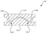
도 23은 본 명세서에 언급된 움직임 조절과 안정성을 구현하기 위하여 단일의 리세스 및 단일의 돌출부를 이용하는 그 외의 다른 인공 디스크(264)를 도시한다. 상부(266)는 단일의 리세스(270)를 포함하고, 바닥(274)은 단일의 돌출부(278)를 포함한다. 리세스(270)와 돌출부(278)는 이들 사이에 평활한 움직임을 제공하기 위하여 둥글고 및/또는 각을 형성하는 연결 표면을 포함하도록 형성된다. 돌출부(278)와 리세스(270)는 관절의 보다 자연스러운 움직임을 제공하고, 인공 관절의 회전을 제한하기 위하여 다각형 형태 또는 그 외의 다른 형태로 형성될 수 있다. 원형 홀(278)과 리세스(270)는 관절의 바닥(274)에 대해 상측(266)의 회전을 제한하지 못한다. 돌출부(278)와 리세스(270)는 타원형, 정방형, 삼각형 또는 그 외의 다른 형태로 형성될 수 있다.23 shows another
도 24는 인공 관절(264)의 횡단면도를 도시한다. 도시된 바와 같이, 리세 스(270)는 둥근 숄더(286)와 리세스의 중심으로부터 전이되는 경사진 외측 벽(282)을 포함하고, 돌출부(278)는 둥근 숄더(294)와 경사진 전이 영역(290)을 가진다. 돌출부의 숄더(294)는 경사진 외측 표면(282)과 접촉하고 이를 가로질러 미끄러지며, 리세스(270)의 숄더(286)는 돌출부의 경사진 전이 영역(290)과 접촉하고 이를 가로질러 미끄러진다.24 shows a cross-sectional view of the
인공 관절(264)을 볼 때, 상부(266)가 바닥(272)에 대해 우측으로 이동된다면, 상부의 우측면은 일반적으로 수평인 표면을 가로질러 수평방향으로 이동되며, 상부의 좌측면은 숄더(286, 294)가 경사진 전이 영역(282, 290)과 연결되고 이를 가로질러 이동됨에 따라 상승한다. 이는 인공 관절(264)의 측면 만곡 또는 굽힘/신장의 경우이다. 따라서, 척추의 자연스러운 움직임과 완벽히 유사하지는 않지만 인공 관절(264)로 인해 유사한 움직임이 구현되며, 관절은 관절로 가해지는 압축력에 의해 도시된 중립 위치로 편향될 것이다(관절이 인간의 척추에 이식 시). 인공 관절(164)의 움직임을 보다 잘 조절하기 위하여, 상측 부분(266)은 도면부호(292)로 도시된 바와 같이 숄더(286) 상의 접촉 지점으로부터 이격되도록 만곡될 수 있다. 추가적으로, 하측 부분(274)은 척추의 자연스러운 움직임을 보다 근접하게 따라하도록 도면부호(296)으로 도시된 바와 같이 후부 부분 내에서 하부를 향하여 경사질 수 있다.When looking at the artificial joint 264, if the
도 25는 도 23 및 도 24에 도시된 인공 관절과 유사한 인공 관절의 상측 부분(298)의 저면도이다. 도시된 바와 같이, 리세스(302)(관절의 바닥에 형상된 해당 돌출부)는 정확히 도시된 바와 같이 삼각형 또는 직사각형 형태 이외의 형태로 형 성될 수 있다. 돌출부와 리세스의 다양한 형태가 관절의 특정의 움직임을 가변시킨다. 예를 들어, 도시된 바와 같이 형태가 형성된 돌출부/리세스는 관절의 회전 또는 측면 만곡 동안 다양한 회전 특성을 제공하거나 또는 상반된 방향이 아니라 한 방향으로 이동될 때 보다 더욱 상승되는 경향이 있을 수 있다. 따라서, 형태는 자연적인 척추의 움직임을 타당하게 따르도록 선택될 수 있고, 압축력에 의해 중립 위치로 관절을 편향시킬 수 있지만 제조하기에 상대적으로 용이한 형태이다.25 is a bottom view of the
도 26은 자연적인 디스크의 환대(annulus, 310)가 제 위치에 배열되는 동안 손상된 척추 디스크의 핵(nucleus)을 교체하기 위하여 이용되는 본 발명의 인공 관절(306)의 이용을 도시한다. 가능한 손상되지 않도록 환대(310)가 배열됨에 따라 인공 관절(306)에 대한 지지부를 제공하는 몇몇의 경우 선호될 수 있으며, 이는 척추골(314) 위에서 관절(306)이 중심에 위치되어 유지되는데 도움이 되거나 또는 관절의 상부가 관절의 바닥 위에서 중심에 위치되어 유지되는데 도움이 된다. 핵을 교환하기 위해 이용되는 인공 관절은 일반적으로 전체 디스크 교체를 위해 이용되는 관절보다 작을 것이다. 상기 도시된 임의의 관절 형상은 적합한 재료로 제조되고 적합한 크기와 형상으로 제조 시 핵 교체 또는 전체 디스크 교체로써 이용될 수 있다.Figure 26 illustrates the use of the
도 27은 관절(318)을 둘러싸는 엘라스토머 밴드(band, 322)를 포함하는 인공 디스크(318)를 도시한다. 밴드(322)는 관절의 움직임을 루즈하게 구속하고, 관절의 바닥 위에서 중심에 위치되도록 관절의 상부를 유지시키는데 도움이 될 수 있다. 임의의 상기 관절 형상은 요구 시 밴드(322)와 같이 일체 구성될 수 있다.Figure 27 illustrates an
도 28은 본 발명에 따르는 대안의 인공 디스크를 도시한다. 인공 관절(326)은 원형 리세스(332)를 가진 기저 부분(330), 토로이드(toroid, 334) 및 토로이드(334) 내에 배열된 원뿔형 또는 프러스토-코니컬 부분을 포함하는 상부(338)를 포함한다. 토로이드(334)는 기저부(330)를 따라 병진운동할 수 있지만 압축력에 의해 기저부의 중심으로 편향된다. 상부(338)는 토로이드(334)의 내측에서 피벗회전할 수 있으며, 원뿔형 부분과 토로이드 사이의 상호 작용으로 인해 피벗회전함에 따라 상승된다.28 shows an alternative artificial disc according to the invention. The artificial joint 326 includes a
도 29는 굽힘/신장 또는 측면 만곡 움직임에 대응하는 위치에 있는 도 28의 관절을 도시한다. 도시된 바와 같이, 토로이드(334)는 기저부(330) 내에서 리세스(332)를 가로질러 미끄러짐에 따라 상승되며, 상부(338)는 피벗 회전함에 따라 상승된다. 조인트(326)는 자연스러운 척추 움직임을 러프하게 따라하고, 상대적으로 제조하기에 용이할 수 있는 대칭 형태를 이용한다. 관절의 굽힘/신장과 측면 만곡은 자연적인 척추를 근접하게 따르며(approximate), 또한 중립 위치로 편향된다. 회전이 구속되지 않는 동안, 이러한 움직임은 조절을 위해 근육 및 주위 조직에 대해 가장 용이하며, 자연적인 척추 상에 형성된 압축력에 의해 적어도 구현된다.Fig. 29 shows the joint of Fig. 28 in a position corresponding to bending / stretching or side curvature movement. As shown, the
도 30에 따라서, 그 외의 다른 인공 관절의 전개된 투시도가 도시된다. 일반적으로 도면부호(350)로 도시된 관절은 도 8 내지 도 22에 도시된 인공 관절과 유사하다. 관절(350)은 2개의 측면 돌출부(362)와 전면 돌출부(358)를 가진 상측 부분(354)를 포함한다. 또한, 관절(350)은 도시된 바와 같이 단일의 리세스로 함께 연결될 수 있는 2개의 측면 리세스(374)와 전면 리세스(370)를 포함하는 하측 부 분(366)을 포함한다. 그러나, 도시된 바와 같이 좁은 연결 부분은 인공 디스크의 움직임에 기여하지 않으며, 제조의 편의성을 제공한다. 관절은 도 8 내지 도 18에 관해 상기 기술된 바와 같이 기능을 한다. 즉, 상측 부분(354)은 전면-후부, 측면 및 회전 병진 움직임을 수행할 수 있는 하측 부분(366)을 가로질러 미끄러진다. 상측 부분(354)이 하측 부분(366)을 가로질러 미끄러짐에 따라, 일반적으로 돌출부(358, 362)는 리세스(370, 374)의 만곡된 표면으로 인해 하측 부분(366)에 대해 수직 방향으로 이동된다. 도면에 도시된 바와 같이, 돌출부(358, 362)는 일반적으로 구형이며, 리세스(370, 374)는 원형의 수직 횡단면을 가진다. 이에 따라, 인공 관절(350)은 척추의 자연스러운 모션에 보다 근접하게 일치되며, 상기 언급된 바와 같이 고유의 안정성을 제공하며, 제조하기에 용이하다.30, an exploded perspective view of another artificial joint is shown. The joint shown generally at 350 is similar to the artificial joint shown in Figures 8-22. The joint 350 includes an
도 8 내지 도 22의 인공 관절과 유사하게, 돌출부(358, 362)는 하측 부분의 중심을 향하여 이동함에 따라 하측 부분(366)에 대해 상향 이동된다. 이러한 수직 움직임에 따라 인공 관절의 네트 팽창(net expansion)이 야기되며, 이에 따라 압축력이 관절로 가해지는 관절에 있어서 관절은 중립 위치를 향하여 편향된다. 또한, 이러한 수직 움직임에 따라 관절은 인간의 척추의 자연스러운 운동학적 움직임에 보다 근접하게 일치되는 움직임을 제공한다. 리세스(370, 374) 내에서 곡률의 기울기와 변화는 특히 수평 움직임에 의해 야기된 수직 움직임의 크기를 조절함으로써 조절될 수 있다.Similar to the artificial joints of Figs. 8-22, the
도 31 내지 도 34는 도 30의 관절(350)의 상측 부분(354)의 추가 상세도를 도시한다. 도 31은 상측 부분(354)의 저면도이다. 도 32 및 도 33은 도 31의 섹션 라인(32, 33)을 따라 절단한 횡단면도이다. 도 34는 상측 부분(354)의 투시도이다. 관절(350)의 한 장점은 관절이 도 11의 관절에 비해 다소 단순하고 보다 균일한 표면 형태와 형상을 이용하는 데 있으며, 동시에 자연적인 척추의 움직임을 근접하게 모사하는 움직임을 구현하는 데 있다. 상측 부분은 반-구형 돌출부(358, 362)를 포함하는 실질적으로 평평한 디스크와 같이 형성될 수 있다. 반-구형 돌출부(358, 362)는 예를 들어 도 11에 도시된 바와 같이 보다 복잡한 돌출부보다 용이한 형태로 형성되고 폴리싱될 수 있다.Figs. 31-34 show additional detail of the
도 35 내지 도 40은 도 30의 관절(350)의 하측 부분(366)의 추가 상세도를 도시한다. 도 35는 하측 부분(366)의 상면도이며, 도 36 내지 도 39는 섹션 라인 36-39를 따라 절단한 도 35의 횡단면도이다. 도 40은 하측 부분(366)의 투시도이다. 도 30 및 도 35 내지 도 40에 도시된 바와 같이, 2개의 측면 리세스(374)는 인공 관절의 후방 하측 부분(366)을 가로질러 서로 연결될 수 있다. 측면 돌출부(362)는 측면 리세스(374)들 사이에서 직접적으로 하측 부분(366)의 후방으로 완전히 이동될 수 없으며, 이는 이러한 형상을 가진 관절을 형성하고 폴리싱하기에 용이할 수 있다.35-40 illustrate additional detail of the
도 36 내지 도 39에 도시된 바와 같이, 전면 리세스(370)의 접촉 표면(378)(관절의 관절연결 동안 전면 돌출부(358)가 상기 표면에 대해 미끄러짐)은 완만하게 만곡되고 기울어진다. 리세스(370)의 접촉 표면(378)에 따라 돌출부(358)는 하측 부분(366)의 중심으로부터 이격되도록 미끄러짐에 따라 하향으로 그리고 관절의 굽힘 및 신장 동안 하측 부분의 중심을 향하여 미끄러짐에 따라 상부를 향하여 그리고 관절이 회전하는 동안 하측 부분을 가로질러 측면 방향으로 이동됨에 따라 상부를 향하여 이동될 수 있다. 접촉 표면(370)의 곡률에 따라 돌출부(358)가 하측 부분의 외측 변부에 보다 인접할 때에 비해 돌출부(358)가 하측 부분(366)의 중심에 인접할 때 수평 움직임의 유닛당 상대적으로 큰 수직 움직임이 야기된다.As shown in Figures 36-39, the
하측 부분(366)의 제조를 보다 용이하게 하기 위하여, 리세스(370, 374)는 도 37 내지 도 39에 도시된 바와 같이 원형의 수직 횡단면을 각각 가질 수 있다. 이에 따라, 원형 그라인딩 또는 폴리싱 공구가 리세스를 형성하기 위하여 제조 동안 하측 부분을 가로질러 움직일 수 있다.To facilitate fabrication of the
도 36 내지 도 39에 도시된 바와 같이, 측면 리세스(374)의 접촉 표면(382)은 전면 리세스(370)의 접촉 표면(378)에 비해 작은 곡률 반경을 가진다. 이와 같이, 측면 리세스(374)의 접촉 표면(382)은 하측 부분(366)의 외측 변부 주위에서 수평방향으로 형성되거나 또는 거의 수평 방향으로 형성되며, 하측 부분의 중심 근처에서보다 가파르게 경사진다. 이에 따라, 측면 돌출부(362)는 하측 부분(366)의 중심으로부터 이격되도록 표면(382)을 가로질러 이동함에 따라 거의 또는 수직 방향 움직임이 수행되지 않으며, 하측 부분의 중심 부분을 향하여 이동됨에 따라 관절의 하측 부분(366)으로부터 상측을 향하여 이격되도록 이동된다. 접촉 표면(382)의 곡률은 측면 돌출부(362)의 수직 움직임이 측면 돌출부가 하측 부분(366)의 중심에 인접할 때 수평 움직임의 유닛당 상당히 크도록 형성된다.36 to 39, the
접촉 표면(378)에 비해 접촉 표면(382)의 보다 중심 부분들의 가파른 경사로 인해 인공 관절(350)을 중립 위치(즉 이동되지 않은 위치)로 편향시키는 네트 복원 력(net restoring force)이 제공된다. 따라서, 접촉 표면(378)의 경사는 심지어 중립 위치에서 전면 돌출부(358)를 하측 부분의 중심으로부터 이격되도록 편향시키지만 측면 접촉 표면(382)의 상대적으로 큰 경사는 측면 돌출부(362)로 추가 전면 이동에 대한 상대적으로 큰 편향을 제공하고, 압축력이 인공 관절(350)로 가해지는 동안 중립 위치에 관절을 유지시킨다.A net restoring force is provided that deflects the artificial joint 350 to a neutral position (i.e., a non-displaced position) due to a steep slope of the more central portions of the
리세스(370, 374)의 접촉 표면(378, 382)의 곡률과 형태에 따라 자연적인 척추의 운동학적 움직임을 따르는 인공 관절(350)의 운동학적 움직임이 구현되며, 또한 관절(350)이 압축하에 있을 때 인공 관절(350)은 중립 위치로 복귀되는 경향이 있다. 중립 위치는 상측 부분이 하측 부분 위에 정렬되고 이의 중심으로부터 이동되지 않은 위치이다(상측 또는 하측 부분은 돌출부로부터 다소 이동되는 기저부를 가질 수 있으며, 이에 따라 상측 및 하측 기저 부분은 심지어 돌출부와 리세스가 중립 위치에 있을지라도 다소 오정렬된다. 이는 본 발명의 범위 내이다.). 이용 시, 인공 관절(350)은 신체에 의해 관절에 가해지는 압축력에 의해 이동되지 않은 중립 위치로 편향될 것이며, 이에 따라 관절의 안정화된다. 인공 관절(350)은 척추의 자연스러운 움직임, 즉 척추의 측면 만곡 또는 회전에 따라 발생되는 회전 및 병진 운동 그리고 척추의 굽힘 및 신장에 따라 발생되는 병진운동의 우수한 유사도(approximation)가 제공된다.The kinematic movement of the artificial joint 350 following the kinematic movement of the natural vertebrae is realized according to the curvature and shape of the contact surfaces 378 and 382 of the
도 41 내지 도 53에 관하여, 본 발명의 그 외의 다른 인공 척추 관절(386)이 도시된다. 인공 관절(386)은 상기 기술된 원리에 따라 기능을 하며, 인공 관절은 본질적으로 안정적이며 척추의 자연스러운 움직임에 근접하게 일치되는 모션을 제 공한다. 관절(386)은 관절이 요구된 범위의 움직임에 따라 네트 팽창이 수행됨으로 인해 안정적이며, 이에 따라 압축력이 관절에 가해지고, 척추 내에서 관절은 중립의 편향되지 않은 위치로 복원되는 경향이 있다.With reference to Figures 41-53, another artificial
도 42 내지 도 46은 도 41의 관절(386)의 상측 부분(390)을 도시하며, 도 48 내지 도 53은 관절의 하측 부분(394)을 도시한다. 도 42는 상측 부분(390)의 투시도를 도시한다. 도 43은 상측 부분(390)의 저면도이며, 도 44 내지 도 47은 도 43의 섹션 라인 44 내지 47을 따라 절단한 상측 부분의 횡단면도를 도시한다. 유사하게, 도 48은 하측 부분(394)의 투시도를 도시하며, 도 49는 하측 부분(394)의 상면도를 도시하고, 도 50 내지 도 53은 도 49의 섹션 라인 50 내지 53을 따라 절단한 하측 부분의 횡단면도를 도시한다.Figs. 42-46 show the
관절(386)은 도 8 내지 18 및 도 30 내지 도 40에서 상기 기술된 관절과 상이하며, 이는 단일의 후부 돌출부(398) 및 후부 리세스(406) 및 2개의 전면 측면 돌출부(402)와 2개의 전면 측면 리세스(410)를 포함한다. 게다가, 상측 부분(390)과 하측 부분(394)은 유사한 방식으로 서로 짝을 이루며, 상기 언급된 것과 유사한 방식으로 기능을 한다.The joint 386 is different from the joints described above in Figures 8-18 and 30-40 with a
관절(386)은 후관절(도 3의 52)의 안정화된 효과를 보다 잘 이용하기 위하여 2개의 전면 돌출부(402)와 단일의 후부 돌출부(398) 및 이에 대응하는 리세스를 포함한다. 관절(386)의 전방 굽힘 동안, 보다 큰 압력이 2개의 전면 돌출부(402)와 전면 리세스(410)에 가해지며, 이에 따라 보다 큰 측면 안정성이 제공된다. 관절(386)의 후방 신장 동안, 보다 큰 압력이 단일의 후부 돌출부(398)와 후부 리세 스(406)에 가해져서 관절의 전방 굽힘 시 제공되는 것보다 다소 작은 측면 안정성이 제공된다. 그러나, 척추의 후부에 기초한 후관절(52)은 관절(386)의 신장 동안 추가적인 측면 안정성을 제공한다. 따라서, 2개의 측면 돌출부(402)와 리세스(410)는 관절(386)의 전면에서 보다 잘 이용된다.The joint 386 includes two
게다가, 도 41 내지 도 53의 관절(386)은 도 30 내지 도 40의 관절(350)과 유사하다. 도 44 내지 도 47에 도시된 바와 같이, 돌출부(398, 402)는 다결정 다이아몬드(PDC)가 이용될 때 상측 부분(390)의 보다 용이한 그라인딩과 폴리싱을 허용하기 위하여 구형 형태를 가진다. 리세스는 PDC 또는 유사한 재료를 이용할 때 원형 회전식 공구를 이용하여 보다 용이한 그라인딩과 폴리싱을 허용하기 위하여 도 50 내지 도 53에 도시된 바와 같이 원형의 수직 횡단면을 가진다. 회전식 공구는 도시된 리세스 형태를 그라인딩하기 위하여 상대적으로 단순한 수평 모션을 통해 움직일 수 있다. 관절(386)은 전체 디스크 교체를 위해 척추 내의 이용가능한 공간과 근접하게 일치되는 형태와 같은 사다리꼴 형태로 절단된다. 관절을 언급하고, 도면에서 용이함을 위해 둥근 것으로 도시된 전술한 본 발명의 인공 관절들 모두는 척추골 몸통과 가장 효과적으로 원활히 상호작용을 하기 위하여 일반적으로 사다리꼴 또는 일반적으로 직사각형 형태로 형성될 수 있다.In addition, the
도 54 내지 도 66에 따라서, 본 발명의 그 외의 다른 인공 척추 관절이 도시된다. 도 54는 관절(414)의 투시도를 도시한다. 도 55 내지 도 60은 관절(414)의 상측 부분(418)을 도시하고, 도 61 내지 도 66은 관절(414)의 하측 부분(422)을 도시한다. 도 55는 상측 부분(418)의 투시도를 도시한다. 도 56은 상측 부분(418)의 저면도를 도시하며, 도 57 내지 도 60은 도 56의 섹션 라인 57 내지 60을 따라 절단한 상측 부분의 횡단면도를 도시한다. 유사하게, 도 61은 하측 부분(422)의 투시도를 도시하고, 도 62는 하측 부분(422)의 상측면도를 도시하며, 도 63 내지 도 66은 도 62의 섹션 라인 63 내지 66을 따라 절단한 하측 부분의 횡단면도를 도시한다.54 to 66, another artificial spinal joint of the present invention is shown. 54 shows a perspective view of the joint 414. FIG. Figs. 55-60 illustrate the
관절(414)은 상기 언급된 관절(386)과 유사하며, 이는 단일의 후부 돌출부(426), 후부 리세스(434) 및 2개의 전면 측면 돌출부(430) 및 2개의 전면 측면 리세스(438)를 포함한다. 관절(414)은 돌출부(426, 430)와 리세스(434, 438)가 관절을 구성하기 위해 이용된 재료에 가해진 스트레스를 추가적으로 감소시키고 관절의 접촉 압력을 추가적으로 하강시키기 위하여 관절(386)보다 크다는 점에서 상이하다.The joint 414 is similar to the above-described joint 386, which includes a
돌출부(426, 430)는 구형의 형태로 형성되며, 리세스(434, 438)는 척추의 자연스러운 움직임과 근접하게 일치되도록 본 명세서에서 기술된 바와 같이 선호되는 움직임을 제공하고, 상기 언급된 바와 같이 단순화된 그라인딩과 폴리싱을 허용하기 위하여 원형의 수직 횡단면을 가진다. 관절(414)의 안정성을 최대화하기 위하여, 돌출부(426, 430)와 리세스(434, 438)는 하측 부분(422)과 상측 부분(418)의 변부로 인접하게 이동되며, 움직임의 선호되는 범위가 유지된다. 이는 관절이 압축될 때 관절을 중립 위치로 복원시키는 경향이 있는 힘을 최대화하고 접촉 지점의 '풋프린트'를 증가시킨다. 실례로서, 하기 치수들은 경추 디스크의 전체 디스크 교체를 위해 적합한 인공 관절을 형성하기 위해 기초로 된다. 상측 부분(418)과 하측 부분(422)은 대략 15.5 mm의 폭과 대략 11.9 mm 길이(전방에서 후방까지)를 가진다. 상측 부분(418)의 상대적으로 평평한 기저부(442)(돌출부(426, 430)들 사이에서 연장됨)는 대략 1.9 mm의 두께를 가진다. 상측 부분(418) 상에서, 후부 돌출부(426)는 대략 11.2 mm의 직경을 가지며, 측면 중심선을 따라 위치된 중심을 가지며, 상측 부분의 후부 변부로부터 대략 1.7 mm에 위치된다. 후부 돌출부(426)는 기저 부분(442)으로부터 대략 5.5 mm의 전체 조합된 두께까지 대략 3.6 mm 연장되도록 배열된다.The
2개의 전면 측면 돌출부(430)는 대략 6.9 mm의 직경을 가지며, 상측 부분(418)의 측면 중심선으로부터 대략 5.35 mm 횡방향으로 그리고 후부 돌출부(426)의 중심의 전방에서 대략 7.2 mm에 위치된 중심을 가진다. 전면 측면 돌출부(430)는 대략 4.8 mm의 전체 조합된 두께까지 기저 부분(442)으로부터 대략 2.9 mm 연장된다. 도 56에서 섹션 라인(57 내지 60)은 돌출부(426, 430)의 중심을 통과한다.
일반적으로, 도 41 내지 도 66의 디스크 및 본 명세서에 도시된 그 외의 다른 유사한 인공 디스크는 도 16에 도시된 구조물을 포함하는 리세스를 가지며, 도 15 또는 도 17에 도시된 바와 같이 움직임 제한 스톱(motion limiting stop)을 포함한다.The two
In general, the disks of Figs. 41-66 and other similar artificial discs shown herein have recesses that include the structure shown in Fig. 16, and as shown in Fig. 15 or 17, (motion limiting stop).
도 67 및 도 68은 도시된 바와 같이 하측 섹션(422)을 형성하기 위해 이용된 그라인딩/폴리싱 공구 경로를 도시한다. 도 67은 관절의 하측 부분(422) 상에 배열된 공구 경로의 상면도이며, 도 68은 리세스 및 공구 컷을 따르는 공구 경로의 투시도를 도시한다. 후부 리세스는 수평방향 호(450)를 통해 15 mm 직경의 원형 그라인딩/폴리싱 공구를 스위핑함으로써 형성되고(이에 따라 그라인딩 직경은 호에 대해 수직함), 여기서 호는 대략 1.8 mm의 반경을 가지며, 호의 중심(454)은 하측 부분(422) 상에 횡방향으로 중심에 위치되며, 중심 기준점(446) 뒤에서 6.4 mm에 배열되고(후부 변부로부터 6.6 mm 또는 전면 변부로부터 대략 5.4 mm 그리고 횡방향 의 중심에 위치됨), 이에 따라 중심(454)은 하측 부분(422)의 상측 표면 위의 대략 4.9 mm에 위치된다. 공구에 의해 최저 지점 그라운드의 내측에 위치되는 후부 리세스(434)의 부분(458)은 그라운드 플랫(ground flat)이다.67 and 68 illustrate a grinding / polishing tool path used to form the
2개의 측면 전면 리세스(438)는 경로 세그먼트(462a, 466a, 470a, 474a, 474b, 470b, 466b, 462b)에 의해 식별된 공구 경로를 가로질러 10.8 mm 직경의 원형 그라인딩/폴리싱 공구를 스위핑함으로써(sweeping) 형성된다. 공구 경로 세그먼트(462a, 462b)는 대략 3.5 mm 길이의 직선이다. 공구 경로 세그먼트(466a, 466b)는 대략 0.9 mm의 반경과 중심(478a, 478b)을 가진 호이다. 공구 경로 세그먼트(470a, 470b)는 대략 1.7 mm 길이의 직선이다. 공구 경로 세그먼트(474a, 474b)는 대략 6 mm의 반경과 공통 중심(482)을 가진 호이다. 중심점(478a, 478b)은 측면 중심선의 각각의 측면에 대해 대략 7 mm에 배열되며, 기준점(446)의 전방에서 대략 4 mm에 배열되고, 중심정(454)의 전방에서 대략 10.6 mm에 위치되고, 하측 부분(422)의 전면 변부로부터 후방으로 대략 1.4 mm에 위치된다. 중심점(482)은 기준점(446)의 전방에서 대략 5.9 mm에 위치되고 측면 중심선을 따라 위치되며 또는 하측 부분(422)의 전면 변부의 전방에서 대략 0.3 mm에 위치된다.The two side front recesses 438 are formed by sweeping a 10.8 mm diameter circular grinding / polishing tool across the tool path identified by the
다양한 공구 경로 세그먼트(462 내지 474)가 도시된 바와 같이 연속적인 경로로 연결되고, 단일의 평면 내에 위치된다. 공구 경로 세그먼트가 위치되는 평면은 도 64에 도시된 바와 같이 전면 리세스(438)의 전방 부분(438a)에 각을 형성하기 위해 하측 세그먼트에 대해 각을 이룬다. 상기 언급된 바와 같이, 이에 따라 상측 부분(418)의 전면 단부는 척추가 구부러지는 동안 하측 부분(422)의 전면 단부 에 대해 다소 하강되고, 척추의 자연스러운 움직임을 모사한다. 도 54 내지 도 68에 도시된 실시예에 대해, 평면은 관절의 전면 측면을 향하여 대략 17°로 하향 경사진다. 이와 같이, 공구 경로(경로 세그먼트(462 내지 474))의 전면 지점(486)은 하측 부분(422)의 상측 표면 위의 대략 0.9 mm에 배열되고, 경로 세그먼트(470a, 470b)는 하측 부분의 상측 표면 위의 대략 3.5 mm에 위치된다.The various tool path segments 462 through 474 are connected in a continuous path as shown and are located in a single plane. The plane in which the toolpath segment is positioned is angled relative to the bottom segment to form an angle in the
공구 경로 세그먼트(462 내지 474)가 배열되는 평면의 기울기는 단순화된 제조 공정이 요구된다면 0일 수 있다. 공구 경로 세그먼트(462 내지 474)의 평면이 기울어질 때, 일반적으로 교체되는 특정 디스크와 일치되도록 조절될 수 있으며, 종종 수평선 아래의 대략 7° 내지 27° 사이의 각도로 경사질 수 있다. 상기 언급된 바와 같이, 중간 경추 인공 디스크는 대략 17°의 기울기를 가진다. 일반적으로 평면의 기울기는 유사한 평균 높이로 전면 리세스(438)를 유지시키고, 상측 부분이 중립 위치에 있을 때 유사한 거리로 하측 부분(422)에 대해 상측 부분(418)의 높이를 유지시키기 위하여 전면 지점(486)의 높이를 조절함으로써 가변된다.The slope of the plane in which the tool path segments 462 to 474 are arranged may be zero if a simplified manufacturing process is required. When the plane of the toolpath segments 462 to 474 is tilted, it can be adjusted to coincide with a particular disc that is typically replaced, and can often be tilted at an angle between approximately 7 and 27 degrees below the horizon. As mentioned above, the intermediate cervical artificial disc has a slope of approximately 17 [deg.]. The slope of the plane generally maintains the
본 명세서에서 인공 척추 관절은 척추의 인공적인 움직임을 보다 근접하게 모사하는 움직임을 제공함에 따라 선호된다. 본 발명의 주요한 특징은 하측 부분에 대해 상측 부분의 병진운동 또는 회전운동에 따라 하측 부분에 대해 상측 부분이 틸팅되는 결합된 움직임을 제공하는 데 있다. 몇몇의 종래 기술의 인공 척추 관절에 따라 병진 운동이 가능하고, 볼과 소켓과 같은 방식으로 관절이 피벗회전할 수 있지만 척추의 자연스러운 움직임을 따르는 병진 운동과 피벗회전 운동이 결합은 제공되지 못한다. 이에 따라, 관절은 척추에 이식되었을 때 부자연스러운 움직임을 제공하며, 본 명세서에 언급된 바와 같이 척추에 부정적인 영향을 미친다. 역으로, 본 발명의 인공 척추 관절은 자연스러운 척추의 움직임을 근접하게 모사하는 움직임을 제공한다.Artificial vertebral joints are preferred herein as they provide motion that more closely mimics the artificial movement of the vertebrae. The main feature of the present invention is to provide a combined movement in which the upper part is tilted with respect to the lower part according to the translation or rotational movement of the upper part with respect to the lower part. Some prior art artificial vertebral joints are capable of translational motion, and joints can be pivotally rotated in the same manner as balls and sockets, but the combination of translational and pivotal motion following the natural movement of the vertebrae is not provided. Thus, joints provide unnatural movements when implanted in the vertebrae and have a negative effect on the spine as referred to herein. Conversely, the artificial vertebral joints of the present invention provide a movement that closely mimics the movement of the natural vertebrae.
본 명세서에 기술된 인공 디스크에 따라 돌출부의 만곡된 표면이 상당히 작은 접촉 표면에 접촉할 때 리세스와 돌출부 사이에 높은 접촉 압력이 야기된다. 따라서, 돌출부를 형성하는데 이용되는 재료는 재료의 변형, 마모, 파괴 또는 그외 다른 저하 없이 매우 높은 압력을 견뎌야 한다. 따라서, 본 발명의 선호되는 실시예는 다결정 다이아몬드 콤팩트(PDC)와 같은 다이아몬드로 제조된 인공 디스크를 제공한다. PDC는 마모와 변형을 견디기 위해 상당히 강성의 재료이다.High contact pressure is created between the recess and the protrusion when the curved surface of the protrusion contacts a fairly small contact surface according to the artificial disc described herein. Thus, the material used to form the protrusions must withstand very high pressures without deformation, wear, breakage or other degradation of the material. Thus, the preferred embodiment of the present invention provides an artificial disc made of diamond, such as a polycrystalline diamond compact (PDC). PDCs are fairly rigid materials to withstand wear and deformation.
Diamicron, Inc.로 양도된 미국 공보 제 2003/0191533호는 다이아몬드를 이용하여 인공 관절을 제조하는 것을 공개하며, 이는 본 명세서에 참조 문헌으로 일체 구성된다. 이러한 공보에 따라 인공 다이아몬드의 인공 관절을 제조하는 방식은 종래 기술에 잘 공지되었다. 본 발명에 따라서, 복잡한 다수의 보호부 또는 다수의 리세스 표면인 다이아몬드 인공 디스크 표면을 제조하는 것은 보다 어렵다. 구형 또는 반구형 리셉터클과 같은 단순한 통상의 표면을 제조하는 것은 상당히 용이하다.U.S. Publication No. 2003/0191533 to Diamicron, Inc. discloses the manufacture of artificial joints using diamond, which is incorporated herein by reference. The manner of manufacturing artificial joints of artificial diamonds according to these publications is well known in the art. According to the present invention, it is more difficult to manufacture a diamond artificial disc surface which is a complex multiple protective portion or a plurality of recessed surfaces. It is considerably easier to manufacture simple conventional surfaces such as spherical or hemispherical receptacles.
본 발명의 인공 디스크를 제조하는 선호되는 방법은 관절 표면을 형성하기 위해 방전 가공(electrical discharge machining, EDM)을 이용한다. 인공 다이아몬드 콤파운드는 선호되는 형태로 러프하게 압착 가공될 수 있다. 싱크 EDM 장치(sink EDM machine)는 부분의 음의 형태가 형성되는 전극과 끼워맞춤될 수 있다. 그 뒤 상기 EDM과 커스톰 전극(custom electrode)은 인공 관절의 일부분의 형태를 형성하고, 다이아몬드 콤파운드를 태우기(burn) 위해 이용된다. 이에 따라 형성된 부분은 다듬질된 표면으로 폴리싱될 수 있다. 따라서, 다이아몬드로부터 인공 디스크를 형성하는 공정은 어려운 공정이며, 인공 디스크 형상의 몇몇의 간략함이 요구될 수 있다.The preferred method of making the artificial disc of the present invention utilizes electrical discharge machining (EDM) to form the joint surface. The artificial diamond compound can be roughly crushed in the preferred form. A sink EDM machine can be fitted with an electrode in which a negative part of the part is formed. The EDM and custom electrodes are then used to form a portion of the artificial joint and burn the diamond compound. The portions thus formed can be polished to a finished surface. Thus, the process of forming an artificial disc from diamond is a difficult process, and some simplicity of the artificial disc shape may be required.
본 발명의 인공 관절의 선호되는 제조 방법은 하측 표면상에서 구형 돌출부를 형성하기 위하여 컵 형태의 그라인딩 및 폴리싱 공구를 이용하고, 만곡된 접촉 표면을 형성하고 리세스를 가로질러 스위핑하기 위하여 원형 형태의 그라인딩 및 폴리싱 공구를 이용한다. 이는 도 31 내지 도 66의 인공 관절의 기하학적 형태의 접촉 표면을 형성하는데 특히 선호된다.A preferred method of manufacturing the artificial joints of the present invention is to use a cup-shaped grinding and polishing tool to form spherical protrusions on the lower surface, to form a curved contact surface, and to grind across the recess, And a polishing tool. This is particularly preferred for forming the contact surfaces of the geometric shapes of the artificial joints of Figures 31-66.
PDC 또는 그 외의 다른 다이아몬드 재료가 선호될지라도, 그 외의 다른 생체 적합성 금속과 세라믹이 이용될 수 있다. 인공 관절의 구조는 각각의 문제점 및 해당 장점 및 다양한 재료로 공지되었다.Although PDC or other diamond materials are preferred, other biocompatible metals and ceramics may be used. The structure of artificial joints is known for each problem and its advantages and various materials.
따라서, 개선된 인공 척추골 디스크가 공개된다. 다양한 변형이 본 발명의 사상과 범위로부터 벗어남이 없이 본 발명에 따라 구현될 수 있다. 첨부된 청구항은 이러한 변형물들을 포함하는 것으로 의도된다.Thus, an improved artificial vertebral disc is disclosed. Various modifications may be made in the present invention without departing from the spirit and scope of the invention. The appended claims are intended to include such modifications.
Claims (51)
Translated fromKoreanApplications Claiming Priority (5)
| Application Number | Priority Date | Filing Date | Title |
|---|---|---|---|
| US88921707P | 2007-02-09 | 2007-02-09 | |
| US60/889,217 | 2007-02-09 | ||
| US91446907P | 2007-04-27 | 2007-04-27 | |
| US60/914,469 | 2007-04-27 | ||
| PCT/US2008/053515WO2008098228A2 (en) | 2007-02-09 | 2008-02-08 | Multi-lobe artificial spine joint |
Publications (2)
| Publication Number | Publication Date |
|---|---|
| KR20090108637A KR20090108637A (en) | 2009-10-15 |
| KR101410181B1true KR101410181B1 (en) | 2014-06-19 |
Family
ID=39682458
Family Applications (1)
| Application Number | Title | Priority Date | Filing Date |
|---|---|---|---|
| KR1020097017374AActiveKR101410181B1 (en) | 2007-02-09 | 2008-02-08 | Multilayer Artificial Spine Joint |
Country Status (11)
| Country | Link |
|---|---|
| US (6) | US8163023B2 (en) |
| EP (2) | EP3130317B1 (en) |
| JP (1) | JP5296711B2 (en) |
| KR (1) | KR101410181B1 (en) |
| CN (1) | CN101715331B (en) |
| AU (1) | AU2008212800B2 (en) |
| CA (2) | CA2825442C (en) |
| DK (1) | DK2114313T3 (en) |
| ES (2) | ES2905157T3 (en) |
| PL (1) | PL2114313T3 (en) |
| WO (1) | WO2008098228A2 (en) |
Cited By (1)
| Publication number | Priority date | Publication date | Assignee | Title |
|---|---|---|---|---|
| KR102217719B1 (en)* | 2020-04-14 | 2021-02-18 | 힐로 이노베이션 | Lumbar Intervertebral Artificial Disc and the method of the Lumbar Intervertebral Artificial Disc insertion |
Families Citing this family (32)
| Publication number | Priority date | Publication date | Assignee | Title |
|---|---|---|---|---|
| US7588590B2 (en) | 2003-12-10 | 2009-09-15 | Facet Solutions, Inc | Spinal facet implant with spherical implant apposition surface and bone bed and methods of use |
| US8562649B2 (en) | 2004-02-17 | 2013-10-22 | Gmedelaware 2 Llc | System and method for multiple level facet joint arthroplasty and fusion |
| US8333789B2 (en) | 2007-01-10 | 2012-12-18 | Gmedelaware 2 Llc | Facet joint replacement |
| US7507242B2 (en) | 2004-06-02 | 2009-03-24 | Facet Solutions | Surgical measurement and resection framework |
| EP1639968A1 (en)* | 2004-09-23 | 2006-03-29 | Cervitech, Inc. | Implant with a part to be inserted and anchored in a bone cavity |
| WO2008058205A1 (en) | 2006-11-07 | 2008-05-15 | Biomedflex, Llc | Medical implants |
| US9005307B2 (en) | 2006-11-07 | 2015-04-14 | Biomedflex, Llc | Prosthetic ball-and-socket joint |
| US8070823B2 (en) | 2006-11-07 | 2011-12-06 | Biomedflex Llc | Prosthetic ball-and-socket joint |
| US20110166671A1 (en) | 2006-11-07 | 2011-07-07 | Kellar Franz W | Prosthetic joint |
| US8308812B2 (en) | 2006-11-07 | 2012-11-13 | Biomedflex, Llc | Prosthetic joint assembly and joint member therefor |
| US8029574B2 (en) | 2006-11-07 | 2011-10-04 | Biomedflex Llc | Prosthetic knee joint |
| US7905919B2 (en) | 2006-11-07 | 2011-03-15 | Biomedflex Llc | Prosthetic joint |
| US8512413B2 (en) | 2006-11-07 | 2013-08-20 | Biomedflex, Llc | Prosthetic knee joint |
| US7914580B2 (en) | 2006-11-07 | 2011-03-29 | Biomedflex Llc | Prosthetic ball-and-socket joint |
| WO2008098228A2 (en) | 2007-02-09 | 2008-08-14 | Diamicron, Inc. | Multi-lobe artificial spine joint |
| DE102007058304A1 (en)* | 2007-12-04 | 2009-06-10 | Global Medical Consulting Gmbh | Disc prosthesis |
| CN102046111A (en) | 2008-06-05 | 2011-05-04 | 斯恩蒂斯有限公司 | Articulating disc implant |
| US8882838B2 (en)* | 2008-06-05 | 2014-11-11 | DePuy Synthes Products, LLC | Articulating disc implant |
| US9220603B2 (en)* | 2008-07-02 | 2015-12-29 | Simplify Medical, Inc. | Limited motion prosthetic intervertebral disc |
| DE102008048739A1 (en)* | 2008-09-24 | 2010-04-01 | Franz Dr. Copf jun. | Disc prosthesis |
| DE102009011648A1 (en)* | 2009-03-04 | 2010-09-09 | Advanced Medical Technologies Ag | Implant system with support elements |
| US9066809B2 (en)* | 2009-05-15 | 2015-06-30 | Globus Medical Inc. | Method for inserting and positioning an artificial disc |
| US8663359B2 (en) | 2009-06-26 | 2014-03-04 | Dimicron, Inc. | Thick sintered polycrystalline diamond and sintered jewelry |
| US9173748B2 (en)* | 2009-08-07 | 2015-11-03 | Ebi, Llc | Toroid-shaped spinal disc |
| US9107763B2 (en)* | 2012-10-04 | 2015-08-18 | DePuy Synthes Products, Inc. | Articulating intervertebral implant |
| US9750613B2 (en) | 2012-11-12 | 2017-09-05 | Wright Medical Technology, Inc. | Stabilized total ankle prosthesis |
| KR20170088402A (en)* | 2014-11-24 | 2017-08-01 | 에프비씨디바이스 에이피에스 | Angulating bone plate |
| CN110831548B (en)* | 2017-05-22 | 2022-07-22 | 公理医学有限公司 | System and method for performing a disc replacement procedure through a lateral approach |
| TWI786139B (en)* | 2018-06-22 | 2022-12-11 | 財團法人工業技術研究院 | Artificial joint |
| US11452618B2 (en) | 2019-09-23 | 2022-09-27 | Dimicron, Inc | Spinal artificial disc removal tool |
| US11197765B2 (en) | 2019-12-04 | 2021-12-14 | Robert S. Bray, Jr. | Artificial disc replacement device |
| US11839554B2 (en) | 2020-01-23 | 2023-12-12 | Robert S. Bray, Jr. | Method of implanting an artificial disc replacement device |
Citations (4)
| Publication number | Priority date | Publication date | Assignee | Title |
|---|---|---|---|---|
| US6146421A (en)* | 1997-08-04 | 2000-11-14 | Gordon, Maya, Roberts And Thomas, Number 1, Llc | Multiple axis intervertebral prosthesis |
| JP2002508679A (en) | 1998-10-22 | 2002-03-19 | エスディージーアイ・ホールディングス・インコーポレーテッド | Artificial facet joint allowing translation and rotation |
| US6770095B2 (en)* | 2002-06-18 | 2004-08-03 | Depuy Acroned, Inc. | Intervertebral disc |
| US20050203626A1 (en) | 2004-03-15 | 2005-09-15 | Sdgi Holdings, Inc. | System and method for stabilizing a prosthetic device |
Family Cites Families (116)
| Publication number | Priority date | Publication date | Assignee | Title |
|---|---|---|---|---|
| US2254549A (en) | 1938-11-12 | 1941-09-02 | Small Louis | Sintered metal composition |
| US3115729A (en) | 1963-01-16 | 1963-12-31 | Cincinnati Milling Machine Co | Centerles grinding machine |
| US3864409A (en) | 1970-11-30 | 1975-02-04 | Bill J Pope | Method For Vinyl Halides |
| US3819814A (en) | 1972-11-01 | 1974-06-25 | Megadiamond Corp | Plural molded diamond articles and their manufacture from diamond powders under high temperature and pressure |
| US4196181A (en) | 1973-03-20 | 1980-04-01 | Preobrazhensky Alexandr Y | Microcrystalline monolithic carbon material |
| US4104344A (en) | 1975-09-12 | 1978-08-01 | Brigham Young University | High thermal conductivity substrate |
| US4055862A (en) | 1976-01-23 | 1977-11-01 | Zimmer Usa, Inc. | Human body implant of graphitic carbon fiber reinforced ultra-high molecular weight polyethylene |
| US4164794A (en) | 1977-04-14 | 1979-08-21 | Union Carbide Corporation | Prosthetic devices having coatings of selected porous bioengineering thermoplastics |
| US4166292A (en) | 1977-09-08 | 1979-09-04 | Carbomedics, Inc. | Stress reinforced artificial joint prostheses |
| US4289123A (en) | 1980-03-31 | 1981-09-15 | Dunn Harold K | Orthopedic appliance |
| EP0176728B1 (en) | 1984-09-04 | 1989-07-26 | Humboldt-Universität zu Berlin | Intervertebral-disc prosthesis |
| CA1283501C (en)* | 1987-02-12 | 1991-04-30 | Thomas P. Hedman | Artificial spinal disc |
| US5425773A (en) | 1992-01-06 | 1995-06-20 | Danek Medical, Inc. | Intervertebral disk arthroplasty device |
| US5258031A (en)* | 1992-01-06 | 1993-11-02 | Danek Medical | Intervertebral disk arthroplasty |
| DE4208116C2 (en) | 1992-03-13 | 1995-08-03 | Link Waldemar Gmbh Co | Intervertebral disc prosthesis |
| GB9217578D0 (en) | 1992-08-19 | 1992-09-30 | Surgicarft Ltd | Surgical implants,etc |
| FR2694882B1 (en) | 1992-08-24 | 1994-10-21 | Sofamor | Intervertebral disc prosthesis. |
| JPH06178787A (en) | 1992-12-14 | 1994-06-28 | Shima Yumiko | Centrum spacer with joint, intervertebral cavity measuring device and centrum spacer pattern |
| US5496318A (en) | 1993-01-08 | 1996-03-05 | Advanced Spine Fixation Systems, Inc. | Interspinous segmental spine fixation device |
| US5676701A (en) | 1993-01-14 | 1997-10-14 | Smith & Nephew, Inc. | Low wear artificial spinal disc |
| US5645596A (en) | 1993-07-07 | 1997-07-08 | Asahi Kogaku Kogyo Kabushiki Kaisha | Ceramic vertebrae prosthesis |
| US6514289B1 (en) | 2000-01-30 | 2003-02-04 | Diamicron, Inc. | Diamond articulation surface for use in a prosthetic joint |
| US6596225B1 (en) | 2000-01-31 | 2003-07-22 | Diamicron, Inc. | Methods for manufacturing a diamond prosthetic joint component |
| US6494918B1 (en) | 2000-01-30 | 2002-12-17 | Diamicron, Inc. | Component for a prosthetic joint having a diamond load bearing and articulation surface |
| US7494507B2 (en) | 2000-01-30 | 2009-02-24 | Diamicron, Inc. | Articulating diamond-surfaced spinal implants |
| US7396505B2 (en) | 1994-08-12 | 2008-07-08 | Diamicron, Inc. | Use of CoCrMo to augment biocompatibility in polycrystalline diamond compacts |
| US7678325B2 (en) | 1999-12-08 | 2010-03-16 | Diamicron, Inc. | Use of a metal and Sn as a solvent material for the bulk crystallization and sintering of diamond to produce biocompatbile biomedical devices |
| US6290726B1 (en) | 2000-01-30 | 2001-09-18 | Diamicron, Inc. | Prosthetic hip joint having sintered polycrystalline diamond compact articulation surfaces |
| US7396501B2 (en) | 1994-08-12 | 2008-07-08 | Diamicron, Inc. | Use of gradient layers and stress modifiers to fabricate composite constructs |
| US6517583B1 (en) | 2000-01-30 | 2003-02-11 | Diamicron, Inc. | Prosthetic hip joint having a polycrystalline diamond compact articulation surface and a counter bearing surface |
| US20040111159A1 (en) | 2000-01-30 | 2004-06-10 | Diamicron, Inc. | Modular bearing surfaces in prosthetic joints |
| US7465219B2 (en) | 1994-08-12 | 2008-12-16 | Diamicron, Inc. | Brut polishing of superhard materials |
| US6425922B1 (en) | 2000-01-30 | 2002-07-30 | Diamicron, Inc. | Prosthetic hip joint having at least one sintered polycrystalline diamond compact articulation surface |
| US7077867B1 (en) | 1994-08-12 | 2006-07-18 | Diamicron, Inc. | Prosthetic knee joint having at least one diamond articulation surface |
| CA2197307C (en) | 1994-08-12 | 2005-03-29 | Bill J. Pope | Prosthetic joint with diamond coated interfaces |
| US6793681B1 (en) | 1994-08-12 | 2004-09-21 | Diamicron, Inc. | Prosthetic hip joint having a polycrystalline diamond articulation surface and a plurality of substrate layers |
| CN1134810A (en)* | 1995-02-17 | 1996-11-06 | 索发默达纳集团股份有限公司 | Improved interbody spinal fusion implants |
| US5782832A (en) | 1996-10-01 | 1998-07-21 | Surgical Dynamics, Inc. | Spinal fusion implant and method of insertion thereof |
| US5895428A (en) | 1996-11-01 | 1999-04-20 | Berry; Don | Load bearing spinal joint implant |
| JPH11137585A (en)* | 1997-11-05 | 1999-05-25 | Chubu Bearing Kk | Artificial vertebral disk |
| US5888226A (en) | 1997-11-12 | 1999-03-30 | Rogozinski; Chaim | Intervertebral prosthetic disc |
| US5899941A (en) | 1997-12-09 | 1999-05-04 | Chubu Bearing Kabushiki Kaisha | Artificial intervertebral disk |
| US6679915B1 (en) | 1998-04-23 | 2004-01-20 | Sdgi Holdings, Inc. | Articulating spinal implant |
| WO1999053871A1 (en) | 1998-04-23 | 1999-10-28 | Cauthen Research Group, Inc. | Articulating spinal implant |
| US6019792A (en) | 1998-04-23 | 2000-02-01 | Cauthen Research Group, Inc. | Articulating spinal implant |
| WO2000004851A1 (en) | 1998-07-22 | 2000-02-03 | Spinal Dynamics Corporation | Threaded cylindrical multidiscoid single or multiple array disc prosthesis |
| US6749635B1 (en) | 1998-09-04 | 2004-06-15 | Sdgi Holdings, Inc. | Peanut spectacle multi discoid thoraco-lumbar disc prosthesis |
| US6113637A (en) | 1998-10-22 | 2000-09-05 | Sofamor Danek Holdings, Inc. | Artificial intervertebral joint permitting translational and rotational motion |
| US6039763A (en)* | 1998-10-27 | 2000-03-21 | Disc Replacement Technologies, Inc. | Articulating spinal disc prosthesis |
| US6368350B1 (en) | 1999-03-11 | 2002-04-09 | Sulzer Spine-Tech Inc. | Intervertebral disc prosthesis and method |
| US6793981B2 (en)* | 1999-03-23 | 2004-09-21 | Dai Nippon Printing Co., Ltd. | Process for producing laminated film, and reflection reducing film |
| US7569176B2 (en) | 1999-12-08 | 2009-08-04 | Diamicron, Inc. | Method for making a sintered superhard prosthetic joint component |
| US7556763B2 (en) | 1999-12-08 | 2009-07-07 | Diamicron, Inc. | Method of making components for prosthetic joints |
| US20100025898A1 (en) | 2000-01-30 | 2010-02-04 | Pope Bill J | USE OF Ti AND Nb CEMENTED TiC IN PROSTHETIC JOINTS |
| US20040199260A1 (en) | 2000-01-30 | 2004-10-07 | Pope Bill J. | Prosthetic joint component having at least one sintered polycrystalline diamond compact articulation surface and substrate surface topographical features in said polycrystalline diamond compact |
| US8603181B2 (en) | 2000-01-30 | 2013-12-10 | Dimicron, Inc | Use of Ti and Nb cemented in TiC in prosthetic joints |
| US6488715B1 (en) | 2000-01-30 | 2002-12-03 | Diamicron, Inc. | Diamond-surfaced cup for use in a prosthetic joint |
| US6709463B1 (en) | 2000-01-30 | 2004-03-23 | Diamicron, Inc. | Prosthetic joint component having at least one solid polycrystalline diamond component |
| US20050203630A1 (en) | 2000-01-30 | 2005-09-15 | Pope Bill J. | Prosthetic knee joint having at least one diamond articulation surface |
| US6410877B1 (en) | 2000-01-30 | 2002-06-25 | Diamicron, Inc. | Methods for shaping and finishing prosthetic joint components including polycrystalline diamond compacts |
| FR2805733B1 (en) | 2000-03-03 | 2002-06-07 | Scient X | DISC PROSTHESIS FOR CERVICAL VERTEBRUS |
| FR2805985B1 (en) | 2000-03-10 | 2003-02-07 | Eurosurgical | INTERVERTEBRAL DISK PROSTHESIS |
| US7601174B2 (en)* | 2000-08-08 | 2009-10-13 | Warsaw Orthopedic, Inc. | Wear-resistant endoprosthetic devices |
| US6592985B2 (en) | 2000-09-20 | 2003-07-15 | Camco International (Uk) Limited | Polycrystalline diamond partially depleted of catalyzing material |
| US20030078660A1 (en) | 2001-02-15 | 2003-04-24 | Dale Clifford | Orthopedic implant and method for orthopedic treatment |
| US6655845B1 (en) | 2001-04-22 | 2003-12-02 | Diamicron, Inc. | Bearings, races and components thereof having diamond and other superhard surfaces |
| US20030019106A1 (en) | 2001-04-22 | 2003-01-30 | Diamicron, Inc. | Methods for making bearings, races and components thereof having diamond and other superhard surfaces |
| US6817550B2 (en) | 2001-07-06 | 2004-11-16 | Diamicron, Inc. | Nozzles, and components thereof and methods for making the same |
| US6740118B2 (en) | 2002-01-09 | 2004-05-25 | Sdgi Holdings, Inc. | Intervertebral prosthetic joint |
| US7717959B2 (en) | 2002-03-30 | 2010-05-18 | Lytton William | Intervertebral device and method of use |
| US20080027548A9 (en) | 2002-04-12 | 2008-01-31 | Ferree Bret A | Spacerless artificial disc replacements |
| US6706068B2 (en) | 2002-04-23 | 2004-03-16 | Bret A. Ferree | Artificial disc replacements with natural kinematics |
| US7066958B2 (en) | 2002-05-10 | 2006-06-27 | Ferree Bret A | Prosthetic components with partially contained compressible resilient members |
| US20040024461A1 (en)* | 2002-05-10 | 2004-02-05 | Ferree Bret A. | Spring and spherical joint artificial disc replacements |
| US7001433B2 (en) | 2002-05-23 | 2006-02-21 | Pioneer Laboratories, Inc. | Artificial intervertebral disc device |
| US6793678B2 (en) | 2002-06-27 | 2004-09-21 | Depuy Acromed, Inc. | Prosthetic intervertebral motion disc having dampening |
| US7066960B1 (en) | 2002-06-28 | 2006-06-27 | Dickman Curtis A | Intervertebral disk replacement |
| US7537614B2 (en) | 2002-09-18 | 2009-05-26 | Synthes Usa, Llc | Implant comprising a two-piece joint |
| AU2003297195A1 (en)* | 2002-12-17 | 2004-07-22 | Amedica Corporation | Total disc implant |
| GB0301085D0 (en) | 2003-01-17 | 2003-02-19 | Krishna Manoj | Articulating spinal disc prosthesis |
| US20040158254A1 (en) | 2003-02-12 | 2004-08-12 | Sdgi Holdings, Inc. | Instrument and method for milling a path into bone |
| US6908484B2 (en) | 2003-03-06 | 2005-06-21 | Spinecore, Inc. | Cervical disc replacement |
| US7105024B2 (en) | 2003-05-06 | 2006-09-12 | Aesculap Ii, Inc. | Artificial intervertebral disc |
| US7270679B2 (en) | 2003-05-30 | 2007-09-18 | Warsaw Orthopedic, Inc. | Implants based on engineered metal matrix composite materials having enhanced imaging and wear resistance |
| DE10330698B4 (en) | 2003-07-08 | 2005-05-25 | Aesculap Ag & Co. Kg | Intervertebral implant |
| DE10339170B4 (en) | 2003-08-22 | 2009-10-15 | Aesculap Ag | Intervertebral implant |
| US20050133277A1 (en) | 2003-08-28 | 2005-06-23 | Diamicron, Inc. | Superhard mill cutters and related methods |
| US7794465B2 (en) | 2003-09-10 | 2010-09-14 | Warsaw Orthopedic, Inc. | Artificial spinal discs and associated implantation instruments and methods |
| US20050187633A1 (en) | 2003-11-10 | 2005-08-25 | Ferree Bret A. | Modular artificial disc replacements (ADRS) that allow translocation and axial rotation |
| US20050154462A1 (en)* | 2003-12-02 | 2005-07-14 | St. Francis Medical Technologies, Inc. | Laterally insertable artificial vertebral disk replacement implant with translating pivot point |
| US20050149196A1 (en) | 2004-01-07 | 2005-07-07 | St. Francis Medical Technologies, Inc. | Artificial spinal disk replacement device with rotation limiter and lateral approach implantation method |
| US20050171610A1 (en) | 2004-01-09 | 2005-08-04 | Sdgi Holdings, Inc. | Mobile bearing spinal device and method |
| US20050165487A1 (en) | 2004-01-28 | 2005-07-28 | Muhanna Nabil L. | Artificial intervertebral disc |
| US7083651B2 (en) | 2004-03-03 | 2006-08-01 | Joint Synergy, Llc | Spinal implant |
| ATE387165T1 (en)* | 2004-03-08 | 2008-03-15 | Impliant Ltd | SPINAL PROSTHESIS |
| US7338527B2 (en)* | 2004-05-11 | 2008-03-04 | Geoffrey Blatt | Artificial spinal disc, insertion tool, and method of insertion |
| US8021428B2 (en) | 2004-06-30 | 2011-09-20 | Depuy Spine, Inc. | Ceramic disc prosthesis |
| US20060020342A1 (en) | 2004-07-21 | 2006-01-26 | Ferree Bret A | Facet-preserving artificial disc replacements |
| US20060041313A1 (en) | 2004-08-19 | 2006-02-23 | Sdgi Holdings, Inc. | Intervertebral disc system |
| US7608333B2 (en) | 2004-09-21 | 2009-10-27 | Smith International, Inc. | Thermally stable diamond polycrystalline diamond constructions |
| US20060069441A1 (en) | 2004-09-29 | 2006-03-30 | Zucherman James F | Posterior approach implant method for assembly of multi-piece artificial spinal disk replacement device in situ |
| US7575600B2 (en) | 2004-09-29 | 2009-08-18 | Kyphon Sarl | Artificial vertebral disk replacement implant with translating articulation contact surface and method |
| US7481840B2 (en) | 2004-09-29 | 2009-01-27 | Kyphon Sarl | Multi-piece artificial spinal disk replacement device with selectably positioning articulating element |
| US20060085077A1 (en) | 2004-10-18 | 2006-04-20 | Ebi, L.P. | Intervertebral implant and associated method |
| US20060149372A1 (en)* | 2004-12-17 | 2006-07-06 | Paxson Robert D | Artificial spinal disc |
| CH697330B1 (en) | 2004-12-28 | 2008-08-29 | Synthes Gmbh | Intervertebral prosthesis. |
| US8911498B2 (en) | 2005-02-10 | 2014-12-16 | DePuy Synthes Products, LLC | Intervertebral prosthetic disc |
| US8449991B2 (en) | 2005-04-07 | 2013-05-28 | Dimicron, Inc. | Use of SN and pore size control to improve biocompatibility in polycrystalline diamond compacts |
| EP1712207B1 (en)* | 2005-04-15 | 2012-05-09 | Eden Spine Europe SA | Intervertebral disc |
| US20060235530A1 (en) | 2005-04-18 | 2006-10-19 | Shelokov Alexis P | Artificial prosthesis |
| US7799080B2 (en) | 2005-04-22 | 2010-09-21 | Doty Keith L | Spinal disc prosthesis and methods of use |
| US8394142B2 (en) | 2005-06-13 | 2013-03-12 | Synthes Usa, Llc | Customizing an intervertebral implant |
| US7726421B2 (en) | 2005-10-12 | 2010-06-01 | Smith International, Inc. | Diamond-bonded bodies and compacts with improved thermal stability and mechanical strength |
| WO2008098228A2 (en) | 2007-02-09 | 2008-08-14 | Diamicron, Inc. | Multi-lobe artificial spine joint |
| US20080302579A1 (en) | 2007-06-05 | 2008-12-11 | Smith International, Inc. | Polycrystalline diamond cutting elements having improved thermal resistance |
| US8663359B2 (en) | 2009-06-26 | 2014-03-04 | Dimicron, Inc. | Thick sintered polycrystalline diamond and sintered jewelry |
- 2008
- 2008-02-08WOPCT/US2008/053515patent/WO2008098228A2/enactiveApplication Filing
- 2008-02-08DKDK08729471.6Tpatent/DK2114313T3/enactive
- 2008-02-08JPJP2009549283Apatent/JP5296711B2/enactiveActive
- 2008-02-08USUS12/028,740patent/US8163023B2/enactiveActive
- 2008-02-08PLPL08729471Tpatent/PL2114313T3/enunknown
- 2008-02-08EPEP16186186.9Apatent/EP3130317B1/enactiveActive
- 2008-02-08CACA2825442Apatent/CA2825442C/enactiveActive
- 2008-02-08CNCN200880009060.2Apatent/CN101715331B/enactiveActive
- 2008-02-08ESES16186186Tpatent/ES2905157T3/enactiveActive
- 2008-02-08ESES08729471.6Tpatent/ES2605411T3/enactiveActive
- 2008-02-08KRKR1020097017374Apatent/KR101410181B1/enactiveActive
- 2008-02-08AUAU2008212800Apatent/AU2008212800B2/enactiveActive
- 2008-02-08CACA2677805Apatent/CA2677805C/enactiveActive
- 2008-02-08EPEP08729471.6Apatent/EP2114313B1/enactiveActive
- 2012
- 2012-04-12USUS13/445,833patent/US8603169B2/enactiveActive
- 2013
- 2013-12-07USUS14/099,945patent/US9078763B2/enactiveActive
- 2015
- 2015-06-30USUS14/788,470patent/US9439772B2/enactiveActive
- 2016
- 2016-08-16USUS15/237,861patent/US9814597B2/enactiveActive
- 2017
- 2017-10-16USUS15/785,130patent/US10098752B2/enactiveActive
Patent Citations (4)
| Publication number | Priority date | Publication date | Assignee | Title |
|---|---|---|---|---|
| US6146421A (en)* | 1997-08-04 | 2000-11-14 | Gordon, Maya, Roberts And Thomas, Number 1, Llc | Multiple axis intervertebral prosthesis |
| JP2002508679A (en) | 1998-10-22 | 2002-03-19 | エスディージーアイ・ホールディングス・インコーポレーテッド | Artificial facet joint allowing translation and rotation |
| US6770095B2 (en)* | 2002-06-18 | 2004-08-03 | Depuy Acroned, Inc. | Intervertebral disc |
| US20050203626A1 (en) | 2004-03-15 | 2005-09-15 | Sdgi Holdings, Inc. | System and method for stabilizing a prosthetic device |
Cited By (3)
| Publication number | Priority date | Publication date | Assignee | Title |
|---|---|---|---|---|
| KR102217719B1 (en)* | 2020-04-14 | 2021-02-18 | 힐로 이노베이션 | Lumbar Intervertebral Artificial Disc and the method of the Lumbar Intervertebral Artificial Disc insertion |
| WO2021209827A1 (en)* | 2020-04-14 | 2021-10-21 | 힐로 이노베이션 | Artificial spinal disc and artificial disc insertion method using same |
| US11559410B2 (en) | 2020-04-14 | 2023-01-24 | Hilo Innovations, Llc | Artificial spinal disc and artificial disc insertion method using the same |
Also Published As
| Publication number | Publication date |
|---|---|
| EP2114313A2 (en) | 2009-11-11 |
| CN101715331B (en) | 2014-03-26 |
| CA2677805A1 (en) | 2008-08-14 |
| EP3130317A1 (en) | 2017-02-15 |
| EP3130317B1 (en) | 2021-11-10 |
| CN101715331A (en) | 2010-05-26 |
| US20150374505A1 (en) | 2015-12-31 |
| US9439772B2 (en) | 2016-09-13 |
| US9078763B2 (en) | 2015-07-14 |
| CA2825442C (en) | 2016-07-05 |
| EP2114313A4 (en) | 2013-03-06 |
| AU2008212800B2 (en) | 2013-09-12 |
| US8603169B2 (en) | 2013-12-10 |
| JP2010517699A (en) | 2010-05-27 |
| US20140172100A1 (en) | 2014-06-19 |
| AU2008212800A1 (en) | 2008-08-14 |
| US20120232661A1 (en) | 2012-09-13 |
| WO2008098228A3 (en) | 2009-12-30 |
| CA2677805C (en) | 2013-09-10 |
| US9814597B2 (en) | 2017-11-14 |
| ES2605411T3 (en) | 2017-03-14 |
| EP2114313B1 (en) | 2016-08-31 |
| WO2008098228A2 (en) | 2008-08-14 |
| DK2114313T3 (en) | 2016-12-19 |
| ES2905157T3 (en) | 2022-04-07 |
| CA2825442A1 (en) | 2008-08-14 |
| US20080195212A1 (en) | 2008-08-14 |
| PL2114313T3 (en) | 2017-03-31 |
| US20170042693A1 (en) | 2017-02-16 |
| US8163023B2 (en) | 2012-04-24 |
| US20180049887A1 (en) | 2018-02-22 |
| JP5296711B2 (en) | 2013-09-25 |
| US10098752B2 (en) | 2018-10-16 |
| KR20090108637A (en) | 2009-10-15 |
Similar Documents
| Publication | Publication Date | Title |
|---|---|---|
| KR101410181B1 (en) | Multilayer Artificial Spine Joint | |
| US8057547B2 (en) | Articulating intervertebral disc prosthesis | |
| MX2007013293A (en) | Intervertebral disc prosthesis. | |
| KR101498657B1 (en) | Artificial intervertebral disc | |
| US20230157835A1 (en) | Artificial spinal disc and artificial disc insertion method using the same |
Legal Events
| Date | Code | Title | Description |
|---|---|---|---|
| PA0105 | International application | Patent event date:20090820 Patent event code:PA01051R01D Comment text:International Patent Application | |
| PG1501 | Laying open of application | ||
| A201 | Request for examination | ||
| PA0201 | Request for examination | Patent event code:PA02012R01D Patent event date:20121119 Comment text:Request for Examination of Application | |
| E902 | Notification of reason for refusal | ||
| PE0902 | Notice of grounds for rejection | Comment text:Notification of reason for refusal Patent event date:20131227 Patent event code:PE09021S01D | |
| E701 | Decision to grant or registration of patent right | ||
| PE0701 | Decision of registration | Patent event code:PE07011S01D Comment text:Decision to Grant Registration Patent event date:20140530 | |
| PR0701 | Registration of establishment | Comment text:Registration of Establishment Patent event date:20140613 Patent event code:PR07011E01D | |
| PR1002 | Payment of registration fee | Payment date:20140613 End annual number:3 Start annual number:1 | |
| PG1601 | Publication of registration | ||
| FPAY | Annual fee payment | Payment date:20170614 Year of fee payment:4 | |
| PR1001 | Payment of annual fee | Payment date:20170614 Start annual number:4 End annual number:4 | |
| FPAY | Annual fee payment | Payment date:20180515 Year of fee payment:5 | |
| PR1001 | Payment of annual fee | Payment date:20180515 Start annual number:5 End annual number:5 | |
| FPAY | Annual fee payment | Payment date:20190614 Year of fee payment:6 | |
| PR1001 | Payment of annual fee | Payment date:20190614 Start annual number:6 End annual number:6 | |
| PR1001 | Payment of annual fee | Payment date:20200612 Start annual number:7 End annual number:7 | |
| PR1001 | Payment of annual fee | Payment date:20210614 Start annual number:8 End annual number:8 | |
| PR1001 | Payment of annual fee | Payment date:20220330 Start annual number:9 End annual number:9 | |
| PR1001 | Payment of annual fee | Payment date:20230614 Start annual number:10 End annual number:10 | |
| PR1001 | Payment of annual fee | Payment date:20250610 Start annual number:12 End annual number:12 |