KR101408189B1 - Water circulation system for ponds, lakes, municipal tanks, and other waters - Google Patents
Water circulation system for ponds, lakes, municipal tanks, and other watersDownload PDFInfo
- Publication number
- KR101408189B1 KR101408189B1KR1020087027526AKR20087027526AKR101408189B1KR 101408189 B1KR101408189 B1KR 101408189B1KR 1020087027526 AKR1020087027526 AKR 1020087027526AKR 20087027526 AKR20087027526 AKR 20087027526AKR 101408189 B1KR101408189 B1KR 101408189B1
- Authority
- KR
- South Korea
- Prior art keywords
- delete delete
- water
- hose
- floating platform
- draft hose
- Prior art date
- Legal status (The legal status is an assumption and is not a legal conclusion. Google has not performed a legal analysis and makes no representation as to the accuracy of the status listed.)
- Expired - Fee Related
Links
Images


Classifications
- B—PERFORMING OPERATIONS; TRANSPORTING
- B01—PHYSICAL OR CHEMICAL PROCESSES OR APPARATUS IN GENERAL
- B01F—MIXING, e.g. DISSOLVING, EMULSIFYING OR DISPERSING
- B01F25/00—Flow mixers; Mixers for falling materials, e.g. solid particles
- B01F25/50—Circulation mixers, e.g. wherein at least part of the mixture is discharged from and reintroduced into a receptacle
- E—FIXED CONSTRUCTIONS
- E02—HYDRAULIC ENGINEERING; FOUNDATIONS; SOIL SHIFTING
- E02B—HYDRAULIC ENGINEERING
- E02B1/00—Equipment or apparatus for, or methods of, general hydraulic engineering, e.g. protection of constructions against ice-strains
- E02B1/003—Mechanically induced gas or liquid streams in seas, lakes or water-courses for forming weirs or breakwaters; making or keeping water surfaces free from ice, aerating or circulating water, e.g. screens of air-bubbles against sludge formation or salt water entry, pump-assisted water circulation
- B—PERFORMING OPERATIONS; TRANSPORTING
- B01—PHYSICAL OR CHEMICAL PROCESSES OR APPARATUS IN GENERAL
- B01F—MIXING, e.g. DISSOLVING, EMULSIFYING OR DISPERSING
- B01F23/00—Mixing according to the phases to be mixed, e.g. dispersing or emulsifying
- B01F23/20—Mixing gases with liquids
- B01F23/23—Mixing gases with liquids by introducing gases into liquid media, e.g. for producing aerated liquids
- B01F23/233—Mixing gases with liquids by introducing gases into liquid media, e.g. for producing aerated liquids using driven stirrers with completely immersed stirring elements
- B01F23/2334—Mixing gases with liquids by introducing gases into liquid media, e.g. for producing aerated liquids using driven stirrers with completely immersed stirring elements provided with stationary guiding means surrounding at least partially the stirrer
- B01F23/23341—Mixing gases with liquids by introducing gases into liquid media, e.g. for producing aerated liquids using driven stirrers with completely immersed stirring elements provided with stationary guiding means surrounding at least partially the stirrer with tubes surrounding the stirrer
- B—PERFORMING OPERATIONS; TRANSPORTING
- B01—PHYSICAL OR CHEMICAL PROCESSES OR APPARATUS IN GENERAL
- B01F—MIXING, e.g. DISSOLVING, EMULSIFYING OR DISPERSING
- B01F23/00—Mixing according to the phases to be mixed, e.g. dispersing or emulsifying
- B01F23/20—Mixing gases with liquids
- B01F23/23—Mixing gases with liquids by introducing gases into liquid media, e.g. for producing aerated liquids
- B01F23/234—Surface aerating
- B01F23/2342—Surface aerating with stirrers near to the liquid surface, e.g. partially immersed, for spraying the liquid in the gas or for sucking gas into the liquid, e.g. using stirrers rotating around a horizontal axis or using centrifugal force
- B01F23/23421—Surface aerating with stirrers near to the liquid surface, e.g. partially immersed, for spraying the liquid in the gas or for sucking gas into the liquid, e.g. using stirrers rotating around a horizontal axis or using centrifugal force the stirrers rotating about a vertical axis
- B—PERFORMING OPERATIONS; TRANSPORTING
- B01—PHYSICAL OR CHEMICAL PROCESSES OR APPARATUS IN GENERAL
- B01F—MIXING, e.g. DISSOLVING, EMULSIFYING OR DISPERSING
- B01F27/00—Mixers with rotary stirring devices in fixed receptacles; Kneaders
- B01F27/80—Mixers with rotary stirring devices in fixed receptacles; Kneaders with stirrers rotating about a substantially vertical axis
- B01F27/91—Mixers with rotary stirring devices in fixed receptacles; Kneaders with stirrers rotating about a substantially vertical axis with propellers
- B—PERFORMING OPERATIONS; TRANSPORTING
- B01—PHYSICAL OR CHEMICAL PROCESSES OR APPARATUS IN GENERAL
- B01F—MIXING, e.g. DISSOLVING, EMULSIFYING OR DISPERSING
- B01F33/00—Other mixers; Mixing plants; Combinations of mixers
- B01F33/50—Movable or transportable mixing devices or plants
- B01F33/503—Floating mixing devices
- C—CHEMISTRY; METALLURGY
- C02—TREATMENT OF WATER, WASTE WATER, SEWAGE, OR SLUDGE
- C02F—TREATMENT OF WATER, WASTE WATER, SEWAGE, OR SLUDGE
- C02F3/00—Biological treatment of water, waste water, or sewage
- C02F3/02—Aerobic processes
- C02F3/12—Activated sludge processes
- C02F3/14—Activated sludge processes using surface aeration
- C02F3/16—Activated sludge processes using surface aeration the aerator having a vertical axis
- C—CHEMISTRY; METALLURGY
- C02—TREATMENT OF WATER, WASTE WATER, SEWAGE, OR SLUDGE
- C02F—TREATMENT OF WATER, WASTE WATER, SEWAGE, OR SLUDGE
- C02F3/00—Biological treatment of water, waste water, or sewage
- C02F3/02—Aerobic processes
- C02F3/12—Activated sludge processes
- C02F3/22—Activated sludge processes using circulation pipes
- C—CHEMISTRY; METALLURGY
- C02—TREATMENT OF WATER, WASTE WATER, SEWAGE, OR SLUDGE
- C02F—TREATMENT OF WATER, WASTE WATER, SEWAGE, OR SLUDGE
- C02F7/00—Aeration of stretches of water
- E—FIXED CONSTRUCTIONS
- E02—HYDRAULIC ENGINEERING; FOUNDATIONS; SOIL SHIFTING
- E02B—HYDRAULIC ENGINEERING
- E02B1/00—Equipment or apparatus for, or methods of, general hydraulic engineering, e.g. protection of constructions against ice-strains
- C—CHEMISTRY; METALLURGY
- C02—TREATMENT OF WATER, WASTE WATER, SEWAGE, OR SLUDGE
- C02F—TREATMENT OF WATER, WASTE WATER, SEWAGE, OR SLUDGE
- C02F1/00—Treatment of water, waste water, or sewage
- C02F1/72—Treatment of water, waste water, or sewage by oxidation
- C02F1/76—Treatment of water, waste water, or sewage by oxidation with halogens or compounds of halogens
- Y—GENERAL TAGGING OF NEW TECHNOLOGICAL DEVELOPMENTS; GENERAL TAGGING OF CROSS-SECTIONAL TECHNOLOGIES SPANNING OVER SEVERAL SECTIONS OF THE IPC; TECHNICAL SUBJECTS COVERED BY FORMER USPC CROSS-REFERENCE ART COLLECTIONS [XRACs] AND DIGESTS
- Y02—TECHNOLOGIES OR APPLICATIONS FOR MITIGATION OR ADAPTATION AGAINST CLIMATE CHANGE
- Y02W—CLIMATE CHANGE MITIGATION TECHNOLOGIES RELATED TO WASTEWATER TREATMENT OR WASTE MANAGEMENT
- Y02W10/00—Technologies for wastewater treatment
- Y02W10/10—Biological treatment of water, waste water, or sewage
- Y—GENERAL TAGGING OF NEW TECHNOLOGICAL DEVELOPMENTS; GENERAL TAGGING OF CROSS-SECTIONAL TECHNOLOGIES SPANNING OVER SEVERAL SECTIONS OF THE IPC; TECHNICAL SUBJECTS COVERED BY FORMER USPC CROSS-REFERENCE ART COLLECTIONS [XRACs] AND DIGESTS
- Y02—TECHNOLOGIES OR APPLICATIONS FOR MITIGATION OR ADAPTATION AGAINST CLIMATE CHANGE
- Y02W—CLIMATE CHANGE MITIGATION TECHNOLOGIES RELATED TO WASTEWATER TREATMENT OR WASTE MANAGEMENT
- Y02W10/00—Technologies for wastewater treatment
- Y02W10/30—Wastewater or sewage treatment systems using renewable energies
- Y02W10/37—Wastewater or sewage treatment systems using renewable energies using solar energy
- Y—GENERAL TAGGING OF NEW TECHNOLOGICAL DEVELOPMENTS; GENERAL TAGGING OF CROSS-SECTIONAL TECHNOLOGIES SPANNING OVER SEVERAL SECTIONS OF THE IPC; TECHNICAL SUBJECTS COVERED BY FORMER USPC CROSS-REFERENCE ART COLLECTIONS [XRACs] AND DIGESTS
- Y10—TECHNICAL SUBJECTS COVERED BY FORMER USPC
- Y10T—TECHNICAL SUBJECTS COVERED BY FORMER US CLASSIFICATION
- Y10T137/00—Fluid handling
- Y10T137/7722—Line condition change responsive valves
- Y10T137/7837—Direct response valves [i.e., check valve type]
- Y10T137/7838—Plural
- Y10T137/7839—Dividing and recombining in a single flow path
- Y—GENERAL TAGGING OF NEW TECHNOLOGICAL DEVELOPMENTS; GENERAL TAGGING OF CROSS-SECTIONAL TECHNOLOGIES SPANNING OVER SEVERAL SECTIONS OF THE IPC; TECHNICAL SUBJECTS COVERED BY FORMER USPC CROSS-REFERENCE ART COLLECTIONS [XRACs] AND DIGESTS
- Y10—TECHNICAL SUBJECTS COVERED BY FORMER USPC
- Y10T—TECHNICAL SUBJECTS COVERED BY FORMER US CLASSIFICATION
- Y10T137/00—Fluid handling
- Y10T137/7722—Line condition change responsive valves
- Y10T137/7837—Direct response valves [i.e., check valve type]
- Y10T137/7898—Pivoted valves
Landscapes
- Chemical & Material Sciences (AREA)
- Engineering & Computer Science (AREA)
- Chemical Kinetics & Catalysis (AREA)
- General Engineering & Computer Science (AREA)
- Life Sciences & Earth Sciences (AREA)
- Environmental & Geological Engineering (AREA)
- Organic Chemistry (AREA)
- Water Supply & Treatment (AREA)
- Hydrology & Water Resources (AREA)
- Mechanical Engineering (AREA)
- Structural Engineering (AREA)
- Civil Engineering (AREA)
- Biodiversity & Conservation Biology (AREA)
- Microbiology (AREA)
- Physical Water Treatments (AREA)
- Aeration Devices For Treatment Of Activated Polluted Sludge (AREA)
- Structures Of Non-Positive Displacement Pumps (AREA)
Abstract
Translated fromKorean
Description
Translated fromKorean본 발명은 연못, 호수, 시영 탱크, 및 다른 수역의 분야에 관한 것이다. 특히 높은 파도가 주기적으로 전개될 수 있는 상대적으로 크고 깊은 수역(body of water)에 대한 순환 시스템의 분야에 관한 것이다. 또한 시영 탱크 또는 유사한 물 탱크 및 컨테이너 내에서와 같은 작고 얕은 수역을 위한 순환 시스템에 관한 것이다.The present invention relates to the field of ponds, lakes, municipal tanks, and other bodies of water. And more particularly to the field of circulation systems for relatively large and deep bodies of water in which high waves can be deployed periodically. And also to circulation systems for small shallow waters such as in municipal tanks or similar water tanks and containers.
본 발명의 하나의 그룹의 개선은 대형 파도(예를 들면, 4 내지 6 피트 높이 또는 더 높은)를 전개할 수 있는 더 크고 더 깊은 수역에 대해 특별히 적용된다. 물의 표면에 부유되는 이러한 수역에 대한 순환 시스템은 각각의 파도의 높이 만큼 수직으로 상승하여야 하고 종종 매우 신속하게(예를 들면 수 초 또는 그 이하 내에) 상승하여야 한다. 통상적인 순환 시스템은 표면에 부유되는 부유 플랫포옴에부착되는 드래프트 호스(draft hose)를 가진다. 호스는 수역 내로 하방으로 연장하며(예를 들면, 20 내지 50 피트 또는 그 이상) 3 피트 정도의 직경을 가질 수 있다. 작동 중, 이 같은 순환 시스템은 대형 물의 용적을 상방으로 취출하여, 부유 플랫폼이 각각의 파도로 상승될 때, 부착된 드래프트 호스도 부유 플랫폼과 함께 상승되어야 한다.The improvement of one group of the invention is particularly applicable to larger and deeper water bodies that can develop large waves (e.g., 4 to 6 feet high or higher). The circulation system for this body of water floating on the surface of the water must rise vertically by the height of each wave and often rise very quickly (for example within a few seconds or less). A typical circulation system has a draft hose attached to a floating platform that floats on the surface. The hose may extend downward into the water body (e.g., 20 to 50 feet or more) and may have a diameter of about three feet. During operation, such a circulation system draws up the volume of the larger water so that when the floating platform is raised in each wave, the attached draft hose must also be raised with the floating platform.
다수의 이러한 순환 시스템에서, 호스로 유입구에 인접한 수평판 또는 다른 구조물을 제공함으로써 드래프트 호스의 바닥으로 이끌어지는 물의 방향 및 레벨을 제어하는 것이 바람직하다. 그러나, 호스 내의 물의 대형 용적은 파도로 상승될 때 호스의 제한된 바닥 또는 입구로부터 역으로 신속하게 벗어날 수 없다는 문제점이 발생한다. 결론적으로, 부유 플랫폼이 각각의 파도로 상승하여 물로 채워진 매우 무거운 호스가 파도로 상방으로 당겨지는 것이 시도된다. 극한의 경우, 응력은 부유 플랫폼 뿐만 아니라 호스 및 시스템의 다른 부분을 손상 또는 파괴시킬 수 있다. 상술된 바와 같이, 이 같은 시스템에서 문제점의 주요 원인은 호스의 물의 기둥이 호스의 제한된 바닥으로부터, 특히, 매 수초에서 4-6 피트 또는 그 이상으로 파도가 치는 높은 바다에서 충분히 빨리 벗어날 수 없다는 것이다. In many such circulation systems, it is desirable to control the direction and level of the water leading to the bottom of the draft hose by providing a horizontal plate or other structure adjacent the inlet with the hose. However, there arises a problem that the large volume of water in the hose can not be quickly disengaged from the limited bottom or inlet of the hose when raised to the wave. In conclusion, it is attempted that the floating platform rises to each wave and a very heavy hose filled with water is pulled upward into the waves. In the extreme, stress can damage or destroy the hose and other parts of the system as well as the floating platform. As noted above, the main cause of problems in such systems is that the water column of the hose can not escape from the limited floor of the hose, particularly, in the high seas where the waves hit from four to six feet or more every few seconds .
높고 격렬한 파도를 전개할 수 있는 크고 깊은 수역은 또한 이러한 순환 시스템에 대한 부유 장치에 대한 문제점이 존재할 수 있다. 즉, 다수의 시스템은 시스템의 중앙 플랫폼의 외측으로 연장하는 세장형 아암에 필수적으로 강성으로 부착되는 플로트(float)를 가질 수 있다. 플로트는 공통적으로 아암의 단부로부터 하방으로 연장하여 물의 표면 상에 아암을 경유하여 플랫폼에 매달리거나 지지되도록 기능한다. 파도가 잔잔한 정상 상태 하에서, 이러한 플로트 장치는 아암 상에 어떠한 큰 측방향력이 가해지지 않고 플로트 주위로 이동하도록 물에 대한 충분한 시간이 있을 때 좋은 작용을 한다. 그러나, 강한 바람 또는 다른 요소가 전개될 때, 파도는 꽤 높고 거칠어진다. 이러한 상황에서, 플로트를 가압하는 물로부터 플로트 상에 가해지는 큰 힘이 있을 수 있다. 플로트 상의 측방향 력은 플로트 및 플랫폼에 단단히 고정되는 세장형 아암 상에 비틀림 력 또는 토크로 변환된다. 플로트 아암의 이러한 비틀림은 결국 고장 지점에 대해 플로트 아암을 약화시킨다. 극한의 경우, 측방향 력은 스냅될 수 있거나 그렇지 않으면 아암을 손상시켜 아암이 물의 상부에 적절히 플랫폼을 지지하지 않도록 한다.Large and deep waters that can develop high and intense waves may also have problems with floating systems for such circulation systems. That is, many systems may have a float that is essentially rigidly attached to the elongate arms that extend outside the central platform of the system. The floats commonly serve to extend downwardly from the end of the arm and to be suspended or supported on the platform via the arm on the surface of the water. Under steady, steady waves, such a float device performs well when there is sufficient time for water to move around the float without any large lateral forces on the arm. However, when strong winds or other elements are developed, the waves are quite high and rough. In this situation, there may be a large force exerted on the float from the water pressurizing the float. The lateral forces on the float are converted into twisting forces or torques on the elongated arms which are securely fixed to the float and platform. This twisting of the float arm eventually weakens the float arm to the point of failure. In extreme cases, the lateral forces may snap or otherwise damage the arm such that the arm does not properly support the platform on top of the water.
본 발명의 다른 개선예는 시영 음료 및 유사한 물 탱크에 특별히 적용된다. 이 같은 탱크 또는 휴대용 물을 위한 다른 컨테이너는 특별한 요구 및 조건을 가진다. 예를 들면, 탱크 내의 모든 물이 완전히 또는 균일하게 혼합되어 탱크의 벽 및 플로어를 따라 그리고 소정의 코너에서 포함되는 데드 포인트에 대한 요구가 전혀 없다. 이러한 혼합은 바람직하게는 순환 시스템에 의해 상대적이고 신속하게 달성되어 작업의 연장된 공간에 걸혀 유지된다. 순환 시스템이 순환수 내로 염소 및 클로라민(chloramine)과 같은 소독제를 용이하고 신속하게 주입하도록 설계되는 것이 바람직하다.Other improvements of the invention apply specifically to municipal drinks and similar water tanks. Such containers for tanks or portable water have special requirements and conditions. For example, there is no requirement for a dead point that is completely or uniformly mixed with all the water in the tank, along the walls and floor of the tank and at a given corner. This mixing is preferably accomplished relatively and quickly by the circulation system and is held in the extended space of the task. It is desirable that the circulation system be designed to facilitate the rapid and rapid injection of disinfectants such as chlorine and chloramine into the circulating water.
이러한 목적 및 다른 목적 및 원하는 특성을 고려하여, 본발명의 적용이 개선되었다.In view of these and other objects and desired characteristics, the application of the present invention has been improved.
본 발명은 연못, 호수, 시영 탱크(municipal tank), 및 다른 수역용 순환 시스템의 다양한 양태에서의 개선을 포함한다.The invention includes improvements in various aspects of pond, lake, municipal tanks, and other water circulation systems.
하나의 세트의 개선에서, 변형된 수평판 설계가 부유 플랫폼으로부터 수역의 깊이 내로 매달리는 드래프트 호스(draft hose)의 도입부에 제공된다. 제 1 설계에서, 판 부재는 서로 피봇되게 장착되는 두 개의 섹션을 가진다. 두 개의 섹션은 수역이 상대적으로 고요할 때 서로 수평으로 정렬되도록 플로트(float)에 의해 편향된다. 수평 연장판 섹션은 호스의 바닥에 인접하여 호스 내로 실질적으로 수평으로 유입수를 지향시키는 기능을 한다. 이러한 방식으로, 수평으로 연장하는 섹션을 구비한 판은 호스 내로 이끌어지는 물의 깊이를 필수적으로 제어 또는 제한한다.In one set of improvements, a modified horizontal plate design is provided at the entrance of a draft hose which hangs from the floating platform into the depth of the water body. In a first design, the plate member has two sections that are pivotally mounted to one another. The two sections are deflected by a float so that they are horizontally aligned with each other when the water is relatively quiet. The horizontal extension plate section functions to direct the influent water substantially horizontally into the hose adjacent the bottom of the hose. In this manner, the plate with the horizontally extending section essentially controls or limits the depth of water that is drawn into the hose.
파도가 높은 악 조건에서, 판 섹션은 바람직하게는 포개지거나 서로를 향하여 하방으로 접어질 수 있고 부유 플랫폼으로서 수직 평면 및 부착된 호스가 파도 위로 상승된다. 이에 대해, 신속되게 상승되는 호스의 바닥으로부터 나오는 물은 판 섹션 상의 플로트의 상방력을 극복하고 서로를 향하여 섹션을 접어지도록 한다. 극한 상태에서, 누출되는 물의 힘은 수직 평면 내에서 서로 실질적으로 인접하게 연장하도록 판 섹션을 서로 접히게 된다. 이와 같이 하여, 완전히 개방 또는 접혀진 위치에 있는 판 섹션은 호스가 파도에 의해 상승될 때 호스의 바닥으로부터 나오는 물의 기둥에 대한 어떠한 저항도 제공되지 않는다. 부유 플랫폼, 호스 및 순환 시스템의 다른 부분에 대한 응력 및 손상은 파도가 높은 상태에서 최소화된다.At high wave conditions, the plate sections can preferably be folded or folded downward toward one another and the vertical plane and the attached hose as the floating platform are raised above the waves. On the contrary, the water coming out from the bottom of the hose which is rapidly lifted overcomes the upward force of the float on the plate section and causes the section to fold toward each other. In the extreme state, the forces of the leaking water collapse the plate sections to each other so as to extend substantially adjacent to one another in the vertical plane. In this way, the plate section in the fully open or folded position is not provided any resistance to the column of water exiting from the bottom of the hose when the hose is lifted by the waves. The stresses and damage to the floating platforms, hoses and other parts of the circulation system are minimized in high wave conditions.
제 2 설계에서, 판 부재는 주변 원형 링으로 베이스에 피봇적으로 장착되는 다수의 파이형 또는 삼각형 섹션을 가진다. 제 1 설계와 비교하면, 삼각형 섹션은 부유 플랫폼 및 부착된 호스가 파도로 상승될 때 서로를 향하지 않고 서로로부터 이격하여 하방으로 포개지거나 붕괴한다. 또한, 제 1 및 제 2 판 설계는 동일한 원하는 결과를 반드시 달성하도록 실질적으로 동일한 방식으로 설계한다.In a second design, the plate member has a plurality of pie-shaped or triangular sections that are pivotally mounted to the base with peripheral circular rings. Compared to the first design, the triangular sections overlap and collapse downwardly away from each other without facing each other when the floating platform and the attached hose are raised to the wave. Also, the first and second plate designs are designed in substantially the same way to achieve the same desired results.
크고 격렬한 웨이브를 전개할 수 있는 수역에 대한 본 발명의 또 다른 양태는 플랫폼의 세장형 아암에 대한 플로트에 대한 적용을 포함한다. 이에 대해, 플로트는 아암에 대해 실질적으로 자유롭게 필수적으로 보편적으로 이동하도록 아암의 단부에 장착된다. 플로트는 아암의 단부 아래가 아닌 위로 연장하고 체인, 케이블, 로프, 및 볼 조인트와 같은 가요성 장치에 의해 연결된다. 물에서 격렬한 파도 또는 힘은 이어서 플로트를 측방향으로 가압할 수 있어 아암 상에 손상 힘 또는 토크를 생성하지 않고 플로트가 운동할 수 있다.Another aspect of the invention for a water body capable of deploying a large and violent wave includes an application to a float for a triangular arm of the platform. On the contrary, the float is mounted on the end of the arm so that it is essentially universally free to move relative to the arm. The float extends above and beyond the end of the arm and is connected by a flexible device such as a chain, cable, rope, and ball joint. Violent waves or forces in the water can then press the float laterally so that the float can move without creating damaging forces or torques on the arms.
본 발명의 또 다른 개선은 음료수 또는 휴대용 물에 대한 컨테이너 또는 시영 탱크 및 유사 탱크로 순환 시스템을 특별히 적용하는 기능을 한다. 이 같은 특정 요구 및 조건을 가진다. 이들 중에서, 시스템은 탱크의 모든 영역에 도달하기 위해 상대적으로 신속하고 유지가능한 방식으로 물을 완전히 혼합하는 것이 요구된다. 또한 시스템은 효과적이고 상대적으로 신속한 방식으로 소독제를 주입하기 위하여 요구된다. 본 발명에서, 드래프트 호스로의 유입 장치는 드래프트 호스 내로 탱크의 바닥 또는 플로어를 가로질러 필수적으로 모든 방향(360도)으로 균일하게 물을 이끌도록 설계된다. 이는 물의 완전한 혼합 및 물 및 벽 및 플로어를 포함하는 탱크의 표면의 소독에 도움이 된다. 시스템은 특히 벽 및 플로어의 표면 상의 바람직하지 않은 암모니아 산화 박테리아의 막을 전개할 수 있는 클로라민으로 소독하는 시영 물 탱크에 적용된다. 이에 대해 본 시스템의 완전한 순환 패턴은 탱크 벽 및 플로어에 대한 및 이에 따른 유동을 발새시켜 클로라민 내의 염소가 바람직하지 않은 표면 박테리아와 효과적으로 접촉하도록 하여 이 박테리아들을 박멸하거나 및/또는 적어도 박테리아의 재 발생을 방지한다.Yet another improvement of the present invention is to specifically apply the circulation system to beverage or portable water containers or municipal tanks and similar tanks. These have specific requirements and conditions. Of these, the system is required to thoroughly mix water in a relatively quick and sustainable manner to reach all areas of the tank. The system is also required to inject disinfectants in an effective and relatively rapid manner. In the present invention, the inlet device to the draft hose is designed to evenly direct water in all directions (360 degrees) across the floor or floor of the tank into the draft hose. This helps to disinfect the surface of the tank, including the water and the walls and floors, with complete mixing of water. The system is particularly applied to municipal water tanks which are disinfected with chloramine, which is capable of developing a film of undesirable ammonia-oxidizing bacteria on the surfaces of walls and floors. In contrast, the complete circulation pattern of the system allows the chlorine in the chloramines to effectively contact undesired surface bacteria, thereby eliminating these bacteria and / or at least regenerating the bacteria prevent.
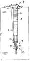
도 1은 연못 또는 호수와 같은 상대적으로 큰 수역에 대한 순환 시스템의 단면도로서, 이 시스템은 에지로 나와서 깊이로 하강하는 수역 내의 전체 유동 패턴을 형성하는, 도면이며,BRIEF DESCRIPTION OF THE DRAWINGS Figure 1 is a cross-sectional view of a circulation system for a relatively large body of water, such as a pond or lake, the system forming an overall flow pattern within a body of water exiting the edge and descending to depth,
도 2 내지 도 4는 도 1의 변형된 플랩 밸브판의 순차적인 작동을 개략적으로 도시하는 도면으로서, 상기 플랩 밸브판은 부유 플랫폼 및 부착된 드래프트 호스가 파도에 의해 상승될 때 반드시 접혀지는, 도면이며,Figures 2 to 4 schematically illustrate the sequential operation of the modified flap valve plate of Figure 1, wherein the flap valve plate is folded when the float platform and the attached draft hose are raised by the waves, Lt;
도 5 내지 도 7은 도 2 내지 도 4의 순차적인 작동에서 변형된 플랩 밸브판의 작동을 추가로 도시하는 도면이며,5 to 7 are views further illustrating the operation of the modified flap valve plate in the sequential operation of Figs. 2 to 4,
도 8은 충분히 개방된 위치로 하방으로 피봇되는 두 개의 섹션을 구비한 변형된 플랩 밸브판을 보여주는 도면이며,Figure 8 is a view showing a modified flap valve plate with two sections pivoted downward into a fully open position,
도 9 및 도 10은 도 1, 2 및 5의 실질적으로 수평한 위치 내에 있는 것을 보여주는 변형된 플랩 밸브 아래로부터 상방으로 본 도면이며,Figures 9 and 10 are top view from below the deformed flap valve showing that it is in a substantially horizontal position of Figures 1, 2 and 5,
도 11은 상이한 배열의 플로트를 구비한 본 발명의 변형된 플랩 밸브판의 또 다른 실시예를 보여주며,Figure 11 shows another embodiment of a modified flap valve plate of the present invention with a different arrangement of floats,
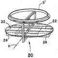
도 12 내지 도 15는 플랩 밸브판의 부가 실시에를 보여주는 도면으로서, 사기 판은 앞의 실시예에서와 같이 서로를 향하지 않고 하방으로 서로로부터 이격하는 피봇 운동을 위해 원형 링에 피봇적으로 장착되는 복수의 삼각형 섹션을 가지는 도면이며,Figs. 12 to 15 show additional embodiments of the flap valve plate, wherein the deformation plates are pivotally mounted to the circular ring for pivoting movement apart from each other downwardly, not toward each other as in the previous embodiment FIG. 2 is a view showing a plurality of triangular sections,
도 16은 도 1의 플로트 실시예의 측면도로서, 상기 플로트 아암은 물의 표면 위로 연장하고 플로트가 그 아래 단단히 부착되는 도면이며,Figure 16 is a side view of the float embodiment of Figure 1 in which the float arm extends over the surface of the water and the float is firmly attached therebelow,
도 17은 도 16의 라인(17-17)을 따라 도시한 도면이며,Figure 17 is a view along line 17-17 of Figure 16,
도 18은 도 16의 순환 시스템을 적용한 도면으로서, 플로트 아암은 도 16의 플로트 아암 대 물의 표면 아래 외측으로 연장하고 플로트는 도 16 및 도 17의 장치로 발생될 수 있는 아암 상의 비틀림 또는 토크 힘을 생성하는 것을 회피하기 위해 체인과 같은 가요성 부재에 의해 아암 위에 위치되는 도면이며,16, wherein the float arm extends outwardly beneath the surface of the float arm-to-body of Fig. 16 and the float is displaced by a torsional or torquing force on the arm, which may be generated by the apparatus of Figs. 16 and 17 And is positioned on the arm by a flexible member, such as a chain, to avoid creating it,
도 19 내지 도 21은 아암 상의 손상 비틀림 또는 토크력을 생성하는 것을 회피하도록 플로트 아암의 외측 단부로 도 16의 플로트를 부착하기 위한 또 다른 가요성 장치를 도시하는 도면이며,Figures 19-21 illustrate another flexible device for attaching the float of Figure 16 to the outer end of the float arm to avoid creating damage torsion or torque forces on the arm,
도 22는 시영 탱크 또는 휴대용 물의 유사 탱크에 이용하기 위해 적용되는 순환 시스템의 측면도이며,Figure 22 is a side view of a circulation system applied for use in a municipal tank or a similar tank of portable water,
도 23은 도 22의 라인(23-23)을 따라 도시된 평면도이며,Figure 23 is a plan view along line 23-23 of Figure 22,
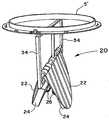
도 24는 드래프트 호스의 하부로의 바닥 유입 장치의 사시도이며,Figure 24 is a perspective view of the bottom inflow device to the bottom of the draft hose,
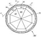
도 25는 도 22의 라인(25-25)을 따라 도시한 바닥 유입 장치의 평면도이며,Figure 25 is a top view of a bottom inflow device shown along line 25-25 of Figure 22,
도 26 및 도 27은 도 22 및 도 24의 유입 장치에 대한 변형도로서, 탱크의 플로어로부터 유입구의 높이가 원하는 경우 조정가능한, 도면이며,Figures 26 and 27 are variations of the inflow device of Figures 22 and 24, wherein the height of the inlet from the tank floor is adjustable if desired,
도 28은 드래프트 호스로의 바닥 유입 장치의 하우징의 변형 형상을 보여주며,Figure 28 shows the deformed shape of the housing of the bottom inflow device with the draft hose,
도 29는 도 28의 라인(29-29)를 따라 도시한 도면이다.Figure 29 is a view along line 29-29 of Figure 28;
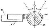
도 1에 개략적으로 도시된 바와 같이, 연못 또는 호수(2)와 같은 대형 수역에 대해 본 발명의 물 순환 시스템(1)은 플랫폼(3)으로부터 호수 바닥(4)을 향하여 호수(5)에 대한 물 유입구(7)로 하방으로 매달리는 드래프트 호스 또는 튜브(5)를 구비한 상부 부유 플랫폼 또는 부유 부분(3)을 포함한다. 부유 플랫폼(3)은 지지되는 복수의 플로트(9)(예를 들면, 3개)를 포함한다. 플로트(9)는 플랫폼(3)의 중앙 축선(13)(도 1)의 외향으로 연장하여 바람직하게는 이에 대해 균일하게 이격된다. 플로트(3)는 중앙 축선(13)으로부터 충분히 멀리 연장하여 태양 패널(11), 전기 모터(15), 디시(dish; 17), 및 임펠러(19)를 포함하는 시스템(1)용, 및 물 유입구(7)의 구조물 및 매달리는 드래프트 호스(5)용 상대적으로 안정된 부양 지지 구조물을 제공하도록 한다. 도 2 내지 도 4에서와 같이 하나 또는 그 이상의 케이블 또는 라인(21)은 또한 부유 플랫폼(3)으로부터 호스(5)의 바닥 부분(5')로 하방으로 연장하도록 제공될 수 있다.1, the water circulation system 1 of the present invention for a large body of water such as a pond or a
도 1에 가장 잘 도시된 바와 같이, 작동 중, 물은 부유 플랫폼(3) 상에 임펠러(19)에 의해 표면(6)으로 호스(5)를 통하여 상방으로 취출된다. 호스(5) 위로 임펠러(19)의 취출은 또한 시스템(1)의 전체 유동 패턴을 형성하기 위해 도움이 되는 드래프트 튜브(5)의 외부를 따라 부가 유동(8)을 유도한다. 도 1의 주변 유도 유동(8) 내로 호스(5)의 바닥 부분(5') 내로 물의 유동의 방향(23)(도 2 참조)을 제한 또는 제어하기 위하여, 실질적인 수평 연장 판 부재(20)가 호스(5)로 유입 개구(7)에 인접하여 지지된다. 도 2에 도시된 바와 같이 유입 개구(7)가 호스(5)의 바닥 부분(5')과 이의 아래로 이격되는 판 부재(20) 사이의 갭 또는 개구(25)에 의해 실제로 형성된다. 판 부재(20)는 실질적으로 수직 축선(V)(도 2)을 중심으로 외측으로 연장한다. 차례로 유입 개구(7)는 축선(V)을 따라 그리고 축선에 따라 연장하는 것이 바람직하다. 이에 대해 도 2의 수평 연장 판 부재(20)는 순환 시스템(1)이 판 부재(20)의 레벨 아래로 물을 취출하는 것을 실질적으로 방지된다. 판 부재(20)는 또한 호스(5) 내로 그리고 위로 판 부재(20) 위로 측방향으로 통과하고, 부유 플랫폼(3)의 외측으로, 수역 내로 하방으로, 그리고 호스(5) 내로 다시 측방향으로 도 1의 수역의 전체 순환을 설정하는데 도움이 된다.As best seen in FIG. 1, during operation, water is drawn upwardly through the
부유 플랫폼(3)이 모든 몇 초 또는 그 이하 4 내지 6 피트 또는 그 이상 상승되는 높은 파도 상태에서, 부유 플랫폼(3) 및 부착된 호스(5)가 도 2의 위치로부터 도 4의 위치로 신속하고 종종 격렬하게 상승될 수 있다. 수평 판 부재(20)를 호스(5)의 바닥 부분(5')으로부터 물의 누출을 과도하게 금지 또는 제한을 방지하기 위하여, 판 부재(20)는 서로 피봇되게 장착되는 두 개의 섹션(22)으로 설계된다. 결론적으로, 부유 플랫폼(3) 및 부착된 호스(5)가 상승될 때(도 3 내지 도 4 참조), 판 부재(20)는 서로를 향하여 하방으로 피봇되는 섹션(22)으로 실질적으로 포개지거나 접혀진다. 도 4의 개방 위치에서 서로 실질적으로 인접한 섹션(22)으로, 호스(5)의 바닥 부분(5')으로부터 누출되는 물의 기둥으로 어떠한 제한이 제공되지 않는다. 이어서 응력은 부유 플랫폼(3) 및 부착된 호스(5) 뿐만 아니라 순환 시스템(1)의 다른 부분 상에서 매우 감소된다.The floating
도 5 내지 도 7은 피봇팅 플랩 밸브(20)의 작동의 추가 도면이다. 도시된 바와 같이 부유 플랫폼(3) 및 호스(5)가 도 2 내지 도 4의 파도에 의해 상승될 때, 밸브판 섹션(22)은 정상 수평 위치(도 5)로부터 공통 수평 축선(H)(도 6)에 대해 서로를 향하여 하방으로 그리고 결국 도 7의 충분히 개방된 위치로 이동한다. 완전히 개방된 위치는 또한 도 8에 도시된다. 완전히 개방된 위치로 이동할 때, 도 2 및 도 5의 수평 위치로 판 섹션(22)을 편향 또는 상승시키는 플로트(24)의 힘은 호스(5)의 바닥 부분(5')으로부터 누출되는 물 기둥의 힘에 의해 극복된다. 플레이트(20) 아래로부터 상방으로 볼 때 도 9 및 도 10에 가장 잘 도시된 바와 같이, 하나 또는 그 이상의 체인(26) 또는 다른 제한 기구가 제공되는 것이 바람직하다. 체인(26)은 섹션(22)(도 9)이 완전히 개방된 위치 및 서로로부터 이격하여 피봇될 수 있는 상방 크기(extent)를 제한하는 기능을 한다. 이러한 방식으로, 섹션(22)은 도 2 및 도 5의 수평 위치를 넘는 것을 방지한다. 도 9의 체인(26)은 각각의 섹션(22)으로 부착되어 실질적으로 도 9 및 도 10의 위치로 섹션을 구비한 수평 축선을 따라 연장한다. 이에 대해 플로트(24)는 소정의 부양 재료(예를 들면, 폐쇄형 셀 폴리스티렌)일 수 있으며 도 9 및 도 10의 스테인레스 강 하우징(28)과 같은 보호 하우징 내에 배치되는 것이 바람직하다. 도 11 내의 볼형 플로트(24')와 같은 다른 플로트 장치는 원하는 경우 이용될 수도 있다. 이러한 장치에서, 스평선을 넘는 섹션(22)의 상방 운동은 세장형 부재 또는 레그(26')에 의해 제한된다. 도시된 바와 같은 레그(26')는 접해서 섹션(22)이 수평선을 넘어 상방으로 이동하는 것을 방지하기 위하여 드래프트 호스 바닥 부분(5')의 원형 링(27)으로부터 하방으로 연장한다.5-7 are additional views of the operation of the pivoting
판 부재 또는 플랩 밸브의 또 다른 실시예(20')가 도 12 내지 도 15에 도시된다. 도시된 바와 같이, 판 부재(20')는 복수의 핀형 또는 삼각형 섹션(22')을 포함한다. 각각의 삼각형(22')의 베이스는 각각의 수평 축선(H')에 대한 피봇 운동을 위해 장착된다(예를 들면, 도 15에 도시된 바와 같이 원형 링(32)의 하부 상에 힌지(30)에 의해). 이어서 인접한 섹션(22')은 서로 교차하는 인접한 축선(H')(도 12 및 도 15)에 대해 피봇한다. 섹션(22')은 플로트(24)를 가지며 다른 제한 기구에 의해 또는 링(32)과 접촉하는 섹션(22')의 베이스 또는 힌지(30)에 의해 도 14의 개방 위치를 넘어 서로로부터 이격하여 하방으로 또는 도 12의 수평 위치를 넘어 상방으로 이동하는 것을 제한할 수 있다. 차례로 링(32)은 레그(34) 또는 다른 기구에 으해 도 8의 바닥 호스 부분(5') 아래 지지된다.Another embodiment 20 'of a plate member or flap valve is shown in Figures 12-15. As shown, the plate member 20 'includes a plurality of pin-like or triangular sections 22'. The base of each triangle 22 'is mounted for pivotal movement with respect to each horizontal axis H' (for example, a hinge 30 (see FIG. 15) on the lower portion of the circular ring 32 ). The adjacent sections 22 'are then pivoted relative to an adjacent axis H' (Figures 12 and 15) that intersect with each other. The section 22'has a
도시된 바와 같은 작동시, 판 부재(20')의 섹션(22')은 도 12의 수평 위치로부터(서로 인접한 삼각형 섹션(22')의 정점(36)으로) 도 14의 개방 위치로 피봇적으로 이동할 수 있다. 도 1 내지 도 11의 제 1 실시예(20)에 비해, 도 12 내지 도 15의 실시예(20')의 삼각형 섹션(22')은 부유 플랫폼(3) 및 부착된 드래프트 호스(5)가 도 2 내지 도 4에서와 같은 파도로 상방으로 상승될 때 서로를 향하지 않고 서로로부터 이격하여 하방으로 겹쳐지거나 접혀진다. 그렇지 않으면, 제 1 및 제 2 판 실시예(20 및 20')는 실질적으로 동일한 원하는 결과를 달성하도록 동일한 방식으로 실질적으로 작동한다.In operation as shown, the section 22 'of the plate member 20' is pivotally moved from the horizontal position of Figure 12 (to the apex 36 of the adjacent triangular section 22 ') to the open position of Figure 14 . ≪ / RTI > Compared to the
높고 격렬한 파도가 전개될 수 있는 대형 수역(2) 상의 원형 시스템(1)으로 발생할 수 있는 또 다른 문제점은 부유 아암에 대한 피로 및 손상이다. 즉, 도 1과 같은 설계는 공통적으로 부유 플랫폼(3) 및 이의 수직 축선(13)의 중앙 섹션(3')의 외측으로 연장하는 도 16 및 도 17의 " 31 "에서와 같은 세장형 아암을 가진다. 아암(31)은 축선(33)(도 17)을 따라 연장되고 플로트(9)(도 16) 위로 외측으로 연장한다. 각각의 아암(31)은 플로트(9)가 외측 단부(31") 및 그 아래 부착되면서 부유 플랫폼(3)의 중앙 섹션(3')으로 부착되는(예를 들면, 수평 피봇) 내측 단부(31')를 가진다. 이러한 방식으로, 각각의 아암(31)은 플로트(9) 위 및 수역(2)의 표면(6) 위로 위치된다.Another problem that can arise with the prototype system 1 on the
파도가 잔잔한 정상 상태 하에서, 이러한 장치는 플로트(9) 주위에 이동하기에 물에 대한 충분한 시간이 있고 큰 측방향력이 플로트(9) 상에 가해질 때 휼륭히 작동된다. 그러나, 크고 격렬한 파도가 전개될 때, 파도 내의 크고 신속한 힘(F)(도 17)은 플로트(9) 대해 수평으로 또는 필수적으로 측방향으로 가압될 수 있다. 이어서 이러한 수평방향력은 부유 플랫폼(3) 및 부유 플랫폼의 수직 축선(13)의 중앙 섹션(3')에 대한 플로트 아암(31) 상의 비틀림 또는 토크력(T)으로 변환된다. 결국, 토크력(T)은 아암(31)을 상기 지점으로 피로하게 하고 아암(31)이 특히 부유 플랫폼(3)의 중앙 섹션(3')으로의 부착부에서, 손상 또는 그렇지 않으면 고장나게 된다.Under steady, steady waves, this device operates well when there is ample time for water to move around the
이러한 문제점을 극복하기 위하여, 도 18의 장치가 개선된다. 여기에서, 세장형 아암(31)은 부유 플랫폼(3)의 중앙 섹션(3')의 외측앞으로 연장되지만 수면(6) 위에서가 아닌 아래로 외측 단부(31")로 연장된다. 이어서 플로트(9)는 아암(31)의 외측 단부(31") 아래가 아닌 위로 위치하여 로프, 케이블, 또는 도 18의 도시된 체인과 같은 가요성 장치에 의해 연결된다. 이러한 방식으로, 플로트(9)는 아암(31)에 대해 필수적으로 보편적으로 실질적으로 자유롭게 이동한다. 물 내의 격렬한 파도 또는 힘은 이어서 플로트를 측방으로 가압되어 아암(31) 상의 손상 힘 또는 토크를 발생시키지 않고 플로트(9)를 이동할 수 있다. 또한, 부유 플랫폼(3)의 중앙 섹션(3')은 중앙 섹션(3')은 파도가 플로트(9)를 가압하는 방향과 관계없이 매우 적게 이동할 때 높은 파도 상태에서 더욱 안정적이 된다.To overcome this problem, the device of Fig. 18 is improved. Here, the
위에서 표시된 바와 같이, 아암(31)의 외측 단부들(31") 사이의 연결 장치는 로프, 케이블, 또는 도 18의 도시된 체인(35)과 같은 가요성 부재일 수 있다. 장치는 또한 도 19 내지 도 21의 볼(37) 및 소켓(39) 설계에서와 같은 다중 방향 운동 자유도를 허용하는 다른 장치일 수 있다. 비틀림 또는 토크력을 감쇄함으로서 이어서 아암(31)이 전개도지 않는다. 또한, 도 18의 실시예에서와 같이, 중앙 섹션(3')은 파도가 플로트(9)를 가압하는 방향과 관계없이 매우 적게 이동할 때 부유 플랫폼(3)의 중앙 섹션(3')은 높은 파도 상태로 더욱 안정되게 남아 있게 된다.As indicated above, the connection between the outer ends 31 "of the
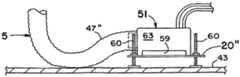
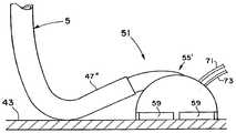
도 22는 시영 또는 유사 탱크(41) 또는 휴대용 물(2)의 컨테이너에서 이용하기 위해 특별히 적용된 본 발명의 순환 시스템(1)을 도시한다. 도시된 바와 같이 탱크(41)는 이로부터 상방으로 연장하는 플로어(43) 및 벽 배열체(45)를 가진다. 시스템(1)은 부유 플랫폼(3), 드래프트 호스(5), 및 임펠러(19)를 포함한다. 드래프트 호스(5)는 관형 메인 바디(47) 및 바닥 유입 장치(51)를 가진다. 드래프트 호스(5)의 메인 바디(47)는 중앙 라인에 대해 가요적이고 부유 플랫폼(3)으로부터 바닥 유입 장치(51)로 연장한다. 도 22에 도시된 바와 같이 드래프트 호스(5)으 메인 바디(47)는 부유 플랫폼(3)으로부터 실질적으로 수직하게 하방으로 매달리는 상부(47')를 가진다. 메인 바디(47)는 또한 탱크 플로어(43)에 지지되어 배치되는 바닥 유입 장치(51)로 상부(47')의 실질적으로 방사형 외측으로 연장하는 하부(47")(도 23 참조)를 가진다.Figure 22 shows a circulation system 1 of the present invention which is specially adapted for use in a municipal or
도 24에 도시된 바와 같이 바닥 유입 장치(51)는 박스형 하우징(55)에 의해 형성된 챔버를 가진다. 챔버의 유출구(57)는 드래프트 호스(5)의 메인 바디(47)의 하부(47")와 유체 소통된다. 도 24 및 25에 도시된 바와 같이 챔버로의 슬롯(59)의 유입구는 실질적인 수직 축선(61)에 대해 실질적으로 개방된다. 이러한 방식으로, 도 22의 임펠러(19)는 탱크 플로어에 인접하여 그리고 바람직하게는 탱크 플로어(43)로부터 우측으로 유입 장치(51)(도 24)를 경유하여 드래프트 호스(5)의 하부(47")내로 물이 이끌어진다. 탱크 플로어(43)에 걸친 이러한 취입은 모든 방향으로부터(도 25) 하우징(55)의 챔버의 슬롯(59)의 유입구를 통하여 그리고 하부 호스부(47") 내로 수직 축선(61)에 대해 내측으로 향하여 실질적으로 360도 실질적으로 반지름 방향이 된다. 이에 대해 유입 슬롯(59)은 측부(61 및 61')(도 24)에 의해 형성되고 하부(61')는 바람직하게는 탱크 플로어(43)에 있다. 상술된 바와 같이, 물은 이어서 탱크(41) 내의 물의 완전한 혼합 동안 탱크 플로어(43)로부터 취출된다. 이러한 혼합을 강화하고 탱크(41)를 통한 층 유동을 유지하는데 도움이 되도록, 유입 슬롯(59)의 수직 높이는 바람직하게는 6 인치 보다 작고 더욱 바람직하게는 약 2 내지 3 인치 정도인 것이 바람직하다.24, the
도 1과 유사한 방식으로 도 22의 시스템(1)은 탱크 물(2) 내의 바람직한 순 환 또는 유동 패턴을 설정된다. 패턴은 벽 배열체(45)의 표면을 따라 하방으로, 드래프트 호스(5)의 바닥 유입 장치(51)로 탱크 플로어(43)를 가로질러 내측으로, 그리고 부유 플랫폼(3)으로 역으로 드래프트 호스(5)의 메인 바디(47) 위로, 수면(6)을 따라 도 22의 부유 플랫폼(3)의 외측에 있다. 이는 탱크(41) 자체의 형상(예를 들면, 원형 또는 직사각형)과 관계없는 경우이다. 패턴에서의 순환은 바람직하게는 사이클을 통한 층 유동을 유지하기에 충분하도록 느리다(예를 들면, 호스 메인 바디(47)를 통한 1ft/sec 및 바람직하게는 0.5 ft/sec). 비록 호스(5)의 직경이 변할 수 있지만(예를 들면, 12 내지 36 인치), 예를 들면 12인치 호스 내의 유동 용적은 분당 350 갈론 정도이다. 이러한 순환 패턴은 호스(5)의 외측으로 도 1의 "8"과 같은 유도된 유동을 설정하며 이 유동은 도 1의 수면(6) 상의 반지름방향 외측으로 조합되고 호수 바닥(4)에 인접하여 반지름방향 내측 유동은 물(2)을 완전히 혼합하기 위한 기능을 한다.In a similar manner to FIG. 1, the system 1 of FIG. 22 is set to the desired circulation or flow pattern in the
도 26 및 도 27의 실시예에서, 실질적인 수평판(20")은 유입 장치(51) 아래 고정된다(예를 들면, 볼트 결합되어). 판(20")에는 조정가능한 길이 레그(60)가 제공된다(예를 들면, 나사형 볼트가 판(20")에 부착된 너트를 관통한다). 이러한 장치로, 유입 슬롯(59)이 원하는 대로(예를 들면, 1 내지 12 인치) 탱크 플로어(43) 위에 위치설정될 수 있어, 플로어(43) 위의 수평 유입 유동 높이가 판(20")에 의해 설정된다.26 and 27, the substantially
바닥 유입 장치(51)의 챔버를 형성하는 하우징(55)은 평평한 직사각형 또는 사각형 측부(63) 및 상부(63')를 가지는 도 22 내지 도 27에 도시되지만 도 28 및 29의 반구형 또는 이글루 형상(55')와 같은 다른 형상을 가질 수 있다. 형상과 관계없이, 유입 슬롯(59)을 통한 하우징(55 또는 55')의 챔버내로의 취입은 도 25 및 도 29에서와 같이 축선(61)에 대해 필수적으로 모든 방향(360도)으로부터 되도록 지향되는 것이 여전히 바람직하다. 일부 분야에서, 탱크 플로어(43)는 다소 경사질 수 있고 축선(61)은 매우 엄격한 수직부로부터 오프셋된다. 그러나, 대부분의 예상된 적용에서, 축선(61)은 여전히 적어도 실질적으로 수직하다.The
아마도 도 22 및 도 29에 가장 잘 도시되고 도 22 내지 29의 양 장치에서, 하나 또는 그 이상의 공기 또는 환기 구멍(65)은 유입 장치(51) 내에 포획되는 소정의 공기 또는 다른 가스가 탱크 물 내로 상방으로 누출되도록 하기 위해 제공도는 것이 바람직하다. 도시된 바와 같이 환기 구멍(65)은 높으며 바람직하게는 유입 장치(51)의 가장 높은 지점에 있다. 이러한 방식으로, 환기 구멍(65)은 공기 또는 가스 포켓이 개선되는 것을 방지하며 그렇지 않으면 탱크 플로어(43)로부터 유입 장치(51)를 팁 또는 리프팅하는 힘이 생성될 수 있다. 도 22 및 도 28에 가장 잘 도시되고 도 22 내지 도 29의 양 장치에서, 호스(5)의 메인 바디의 하부(47")의 부분은 바람직하게는 탱크 플로어(43)에 배치된다. 탱크 내의 물 레벨이 상승 및 하강할 때, 반지름방향으로 연장하는 하부(47")의 길이가 대응하여 짧아지고 길어진다. 이어서 탱크 플로어(43) 및 부유 플랫폼(3)의 하부 지점에 인접한 주요 고정부는 따라서 도 22의 전체 구성을 유지하도록 수면(6) 상에 수평으로 표류한다. 22 and 29, one or more air or
음료 또는 휴대용 물의 처리 및 시영 물 탱크(41)에 대한 도 22의 시스템(1) 의 또 다른 적용예는 물(2)의 순환 패턴 내로 소독제 또는 다른 재료(예를 들면, 화학물)에 대한 라인(71 및 73)의 삽입이다. 라인(71 및 73)은 바닥 유입 장치(51)와 유체 소통되고 이에 대한 주입은 도시된 바와 같이 바닥 유입 장치(51)의 하우징(55 또는 55')의 챔버 내로 직접 되는 것이 바람직하다. 이러한 방식으로, 염소, 클로라민과 같은 주입된 소독제는 탱크 물(2) 내에서 신속하고 완전히 혼합되어 순환 시스템(1)에 의해 유지된다.Another application of the system 1 of FIG. 22 to the treatment of beverages or portable water and the
상술된 바와 같이, 도 22의 시스템(1)은 탱크 물(2) 내의 바람직한 순환 또는 유동 패턴을 설정한다. 패턴은 벽 배열체(45)의 표면을 따라 그리고 이 표면에 대해 하방으로, 드래프트 호스(5)의 바닥 유입 장치(51)로 탱크 플로어(43)를 가로질러 내측으로, 그리고 부유 플랫폼(3)으로 역으로 드래프트 호스(5)의 메인 바디(47) 위로, 수면(6)을 따라 도 22의 부유 플랫폼(3)의 외측에 있다. 또한 상술된 바와 같이 유동 패턴은 층류 또는 적어도 거의 층류인 것이 바람직하다. 도 22의 시영 탱크 물은 이어서 완전히 혼합되어 데드 스폿(dead spot) 및 바람직하지 않은 노화된 물을 회피하도록 한다. 물(2)에 부가되는 소독제 또는 다른 화학물(예를 들면, 주입 라인(71 및 73)을 통하여)은 신속하고 균일하게 분배된다. 이는 물(2)을 신속하게 염소처리하기 위해 필요할 때(종종 파단-지점-염소처리로서 지칭됨) 비상으로 특히 중요할 수 있다.As described above, the system 1 of Fig. 22 establishes the desired circulation or flow pattern in the
벽 배열체(45) 및 탱크 플로어(43)의 표면에 인접하거나 이 표면에 대해 실제로 유동하는 본 발명의 원형 패턴의 부분은 박테리아(예를 들면, 암모니아 산화 박테리아 또는 질화 박테리아)를 제어하는데 동일하게 유익하며, 박테리아는 얇은 막으로서 필수적으로 탱크 벽 및 플로어에 매달리거나 부착될 수 있다. 이 같은 박테리아는 암모니아를 아질산염으로 변환함으로써 생존 및 성장 뿐만 아니라 재생산하기 위해 에너지를 얻는다. 다음으로 아질산염은 비록 낮은 농도이지만 사람에게 매우 유해할 수 있다.The portion of the circular pattern of the present invention which adjoins or actually flows against the surface of the
박테리아를 지지하는 암모니아의 공급원은 크롤라민(예를 들면 액체 염소 및 암모니아의 4:1 또는 그 이상의 비율) 대 과거에서와 같은 단지 염소의 상대적인 최근의 이용에 주로 관련된다. 다른 것 중에서, 크롤라민은 조작자가 처리하기에 더 값싸고 더 안전하고 자체적으로 염소 보다 더 안정되고 더 길게 존속하는 장점을 가진다. 소독 공정은 또한 홀로 이용되는 염소 보다 더 작은 바람직하지 않은 부산물을 생성하고 더 느려지는 경향이 있다. 탱크 물의 pH 및 온도 및 염소/암모니아의 비율을 포함하는 많은 요소에 따라, 혼합물 내의 암모니아는 염소와 화학적으로 관련하여 안전하게 남아 있으며 박테리아를 위한 음식으로서 기능하도록 암모니아 자유롭게 되지 않는다. 불행하게도, 염소 측부가 계속적으로 물의세정이 주요 기능을 수행하는 것이 계속적으로 저하 또는 소모될 때 원하는 비율(예를 들면, 4 : 1)은 항상 손상된다. 근접하여 모니터링되지 않는 경우, 비율은 아질산염의 바람직하지 않은 생성을 초래하는 박테리아를 공급하기 위해 자유롭게 되는 원하는 범위 및 암모니아로부터 얻을 수 있다. 그러나, 이 같은 모니터링은 염소 레벨을 위한 체크가 암모니아 레벨에 대해 거의 알려지지 않을 때 어려우며 암모니아 레벨을 위한 체킹은 안전한 레벨을 보여주지만 소모된 위험한 박테리아가 아질산염을 형성할 수 있기 때문에 안전하다는 것은 잘못된 것이다. 아질산염에 대한 체킹은 종종 클로라민 비율을 간단히 변화시킴으로써 회피하거나 염소의 신속 부가를 함으로써 회피된 후 길어지는 문제점을 표시한다. 본 발명에 의해 수행되는 바와 같이 문제점에 대한 바람직한 해결책은 제 1 장소에서 박테리아 증식을 하지 않을 수 있다.The source of ammonia to support the bacteria is primarily concerned with the relative recent utilization of chlorine only (such as in the past versus 4: 1 or more of the ratio of liquid chlorine and ammonia). Among other things, crawlamine has the advantage that it is cheaper, more safe for the operator to handle, more stable and longer lasting than chlorine itself. The disinfection process also tends to produce undesirable by-products that are smaller than chlorine used alone and to be slower. Depending on many factors, including the pH and temperature of the tank water and the ratio of chlorine / ammonia, the ammonia in the mixture remains chemically related to chlorine and does not become ammonia free to function as food for the bacteria. Unfortunately, the desired proportion (e.g., 4: 1) is always compromised when the chlorine side continues to degrade or consume continuously cleaning the water to perform its primary function. If not closely monitored, the ratio can be obtained from the desired range and ammonia, which is freed up to supply bacteria that cause undesirable production of nitrite. However, such monitoring is difficult when the check for chlorine levels is poorly known for the ammonia level, and checking for ammonia levels shows a safe level, but it is incorrect to say that the dangerous bacteria consumed can be nitrite and thus safe. Checking for nitrites often indicates a problem that is avoided by simply changing the chloramine ratio or by avoiding the rapid addition of chlorine and then lengthening. A preferred solution to the problem, as performed by the present invention, may not be bacterial growth in the first location.
즉, 바람직하지 않은 박테리아는 탱크 벽 및 플로어 뿐만 아니라 플로어에 고정된 입자에 매달리거나 부착될 수 있다. 매우 높은 퍼센티지의 박테리아(예를 들면, 85%)가 바로 바닥 1인치 또는 시영 탱크의 바닥에 있거나 나머지(예를 들면 15%)가 탱크 내부의 다른 구조 부재(예를 들면, 지지 필러) 또는 탱크 벽에 매달린다. 결론적으로, 종래 시스템에서, 종종 탱크 플로어 위에 일 또는 2 피트 및 적어도 높은 곳에 호스 유입구를 세팅함으로써 탱크의 바닥 몇 인치로부터 물이 취입되는 것을 회피하는 것이 실시되었다. 바닥 몇 인치 또는 그 이상은 이어서 순환 패턴의 부분이 아니며 대부분에 대해 소독제(예를 들면, 염소)가 박테리아와 접촉하여 죽이지 않는다. 바람직하지 않은 박테리아는 시영 물 탱크(41) 내에서 번성하게 된다.That is, undesirable bacteria can be suspended or attached to particles fixed to the floor as well as to tank walls and floors. A very high percentage of bacteria (e.g., 85%) may be present at the bottom of an inch or bottom of the municipal tank or the rest (e.g., 15%) may be present in other structural members (e.g., Hang on the wall. Consequently, in conventional systems, it has often been practiced to avoid the introduction of water from several inches of the bottom of the tank by setting the hose inlet at one or two feet and at least high above the tank floor. The bottom several inches or more is not then part of the circulation pattern, and for the most part a disinfectant (eg chlorine) does not contact the bacteria and kill. Undesirable bacteria multiply within the
이는 극한의 경우 아질산염의 레벨이 안전하지 않게 될 때 오염물 제거를 위해 탱크를 차단하기 위하여 또는 예를 들면 라인(71, 73)들 중 하나를 통하여 염소를 부가함으로써 물(2)을 신속하게 염소화하는 것(파단(break)-지점(point)-질화(chlorination))이 요구된다. 두 작용은 바람직하지 않을 수 있고 종종 비효율적인 해결책이다. 그러나, 도 22의 시스템(1)의 순환 또는 유동 패턴 때문에, 염소화된 물이 박테리아와 접촉하여 죽이기 위해 탱크 플로어(43)의 표면을 가로질러 그리고 벽 배열체(45)의 표면에 대해 이 표면에 의해 통과된다. 박테리아가 이미 탱크내에 존재하면, 본 시스템(1)은 반드시 모두 세정 표면을 떠나는 시간에 얇은 층을 제거 및 죽이는 박테리아의 막을 가로질러 걷어낸다. 이에 대해 일부 적용에서, 생성물로부터 더욱 점차로 플로싱되거나 세정되도록 탱크 플로어 상에 생성되는 큰 침전물 또는 박테리아를 구비한 현존 탱크 내의 도 26 및 도 27의 조정가능한 높이 실시예를 이용하는 것이 바람직할 수 있다. 유입 장치(51)는 판(20")이 필수적으로 전체 탱크 세정을 유지하도록 자체적으로 플로어(43) 상에 직접 배치될 때까지 점차적으로 낮추어질 수 있다. 이 같은 방법으로, 암모니아 산화 박테리아는 성장이 제거 및/또는 방지 또는 적어도 금지된다.This can be achieved by rapidly chlorinating
상술된 공개물은 첨부된 도면에 대해 상세하게 설명되는 본 발명의 다수의 실시예가 제시된다. 본 기술분야의 기술자는 다양한 변화, 변형, 다른 구조적 장치, 및 다른 실시에가 첨부된 청구범위에서 제시된 바와 같이 본 발명의 범위로부터 이탈하지 않고 본 발명의 기술 하에서 실시된다는 것이 인정된다.The foregoing disclosure discloses a number of embodiments of the present invention that are described in detail with reference to the accompanying drawings. It will be appreciated by those skilled in the art that various changes, modifications, other structural arrangements, and other implementations may be made without departing from the scope of the present invention as set forth in the appended claims.
Claims (39)
Translated fromKoreanApplications Claiming Priority (5)
| Application Number | Priority Date | Filing Date | Title |
|---|---|---|---|
| US79109106P | 2006-04-10 | 2006-04-10 | |
| US60/791,091 | 2006-04-10 | ||
| PCT/US2007/008906WO2007120692A2 (en) | 2006-04-10 | 2007-04-09 | Water circulation systems for ponds, lakes, municipal tanks, and other bodies of water |
| US11/733,009 | 2007-04-09 | ||
| US11/733,009US7517460B2 (en) | 2006-04-10 | 2007-04-09 | Water circulation systems for ponds, lakes, municipal tanks, and other bodies of water |
Related Child Applications (1)
| Application Number | Title | Priority Date | Filing Date |
|---|---|---|---|
| KR1020137031073ADivisionKR101450021B1 (en) | 2006-04-10 | 2007-04-09 | Water circulation systems for ponds, lakes, municipal tanks, and other bodies of water |
Publications (2)
| Publication Number | Publication Date |
|---|---|
| KR20090015058A KR20090015058A (en) | 2009-02-11 |
| KR101408189B1true KR101408189B1 (en) | 2014-06-17 |
Family
ID=38610145
Family Applications (4)
| Application Number | Title | Priority Date | Filing Date |
|---|---|---|---|
| KR1020087027526AExpired - Fee RelatedKR101408189B1 (en) | 2006-04-10 | 2007-04-09 | Water circulation system for ponds, lakes, municipal tanks, and other waters |
| KR1020147028689AExpired - Fee RelatedKR101624204B1 (en) | 2006-04-10 | 2007-04-09 | Water circulation systems for ponds, lakes, municipal tanks, and other bodies of water |
| KR1020137031073AExpired - Fee RelatedKR101450021B1 (en) | 2006-04-10 | 2007-04-09 | Water circulation systems for ponds, lakes, municipal tanks, and other bodies of water |
| KR1020147009821AExpired - Fee RelatedKR101505383B1 (en) | 2006-04-10 | 2007-04-09 | Water circulation systems for ponds, lakes, municipal tanks, and other bodies of water |
Family Applications After (3)
| Application Number | Title | Priority Date | Filing Date |
|---|---|---|---|
| KR1020147028689AExpired - Fee RelatedKR101624204B1 (en) | 2006-04-10 | 2007-04-09 | Water circulation systems for ponds, lakes, municipal tanks, and other bodies of water |
| KR1020137031073AExpired - Fee RelatedKR101450021B1 (en) | 2006-04-10 | 2007-04-09 | Water circulation systems for ponds, lakes, municipal tanks, and other bodies of water |
| KR1020147009821AExpired - Fee RelatedKR101505383B1 (en) | 2006-04-10 | 2007-04-09 | Water circulation systems for ponds, lakes, municipal tanks, and other bodies of water |
Country Status (9)
| Country | Link |
|---|---|
| US (4) | US7517460B2 (en) |
| EP (1) | EP2004556B1 (en) |
| KR (4) | KR101408189B1 (en) |
| CN (3) | CN104355390B (en) |
| AU (2) | AU2007238808B2 (en) |
| CA (1) | CA2649931C (en) |
| EG (1) | EG25089A (en) |
| MX (2) | MX2008012949A (en) |
| WO (1) | WO2007120692A2 (en) |
Families Citing this family (35)
| Publication number | Priority date | Publication date | Assignee | Title |
|---|---|---|---|---|
| US7306719B2 (en)* | 2002-12-31 | 2007-12-11 | Psi-Ets, A North Dakota Partnership | Water circulation systems for ponds, lakes, and other bodies of water |
| US7332074B2 (en)* | 2002-12-31 | 2008-02-19 | Psi-Ets, A North Dakota Partnership | Water circulation systems for ponds, lakes, and other bodies of water |
| EP1896370A4 (en) | 2005-06-10 | 2011-09-28 | Process Solutions Inc | Electrolytic cell and system for treating water |
| US8118477B2 (en)* | 2006-05-08 | 2012-02-21 | Landmark Structures I, L.P. | Apparatus for reservoir mixing in a municipal water supply system |
| AR060106A1 (en) | 2006-11-21 | 2008-05-28 | Crystal Lagoons Corp Llc | PROCESS OF OBTAINING LARGE WATER BODIES OVER 15,000 M3 FOR RECREATIONAL USE WITH COLORING, TRANSPARENCY AND CLEANING FEATURES SIMILAR TO THE TROPICAL POOLS OR SEA TROPICAL SEA AT LOW COST |
| US20090083097A1 (en)* | 2007-09-20 | 2009-03-26 | Chris Boyd | Process for water storage facilities |
| US8226292B1 (en)* | 2008-08-29 | 2012-07-24 | Medora Environmental, Inc. | Submersible, circulation system for relatively small bodies of water such as a small pond |
| CL2008003900A1 (en) | 2008-12-24 | 2009-03-13 | Crystal Lagoons Curacao Bv | Water filtration process of a pond, without filtering the entire water, which comprises a) emitting ultrasonic waves in the pond; b) add a flocculant; c) suction the floccules with a vacuum cleaner towards an effluent collection line; d) filter said effluent and return the filtered flow to the pond. |
| US8500321B2 (en)* | 2009-03-17 | 2013-08-06 | Medora Environmental, Inc. | Collapsible water circulation system for enclosed tanks |
| CA2686250C (en)* | 2009-11-12 | 2016-10-11 | Fountainhead, Llc | Floating treatment streambed |
| KR101207955B1 (en) | 2010-03-18 | 2012-12-04 | 안익태 | The water quality improvement system in use of the solar cell |
| US8523425B2 (en) | 2010-07-01 | 2013-09-03 | Mark Malmquist | Reservoir tank water mixing system |
| US8523984B2 (en) | 2010-09-19 | 2013-09-03 | Medora Environmental, Inc. | Water circulation systems with air stripping arrangements for municipal water tanks, ponds, and other potable bodies of water |
| KR101048970B1 (en)* | 2011-02-16 | 2011-07-12 | (주)에코코 | Water circulation system installed in parks and lakes |
| KR101036176B1 (en)* | 2011-02-16 | 2011-05-23 | (주)에코코 | Water treatment stirrer |
| JO3415B1 (en) | 2011-03-30 | 2019-10-20 | Crystal Lagoons Tech Inc | System for treating water used for industrial purposes |
| US8454838B2 (en) | 2011-03-30 | 2013-06-04 | Crystal Lagoons (Curacao) B.V. | Method and system for the sustainable cooling of industrial processes |
| US8465651B2 (en) | 2011-03-30 | 2013-06-18 | Crystal Lagoons (Curacao) B.V. | Sustainable method and system for treating water bodies affected by bacteria and microalgae at low cost |
| US8911219B2 (en)* | 2011-09-21 | 2014-12-16 | Medora Environmental, Inc. | Submersible water circulation system for enclosed tanks |
| GB2509605B (en) | 2012-12-19 | 2015-07-29 | Crystal Lagoons Curacao Bv | Localized disinfection system for large water bodies |
| US10029924B2 (en) | 2013-02-08 | 2018-07-24 | Medora Environmental, Inc. | Method and apparatus for treating potable water in municipal and similar water tanks |
| WO2015061310A1 (en)* | 2013-10-22 | 2015-04-30 | Medora Environmental, Inc. | Air-powered water circulation systems for ponds |
| US9920498B2 (en) | 2013-11-05 | 2018-03-20 | Crystal Lagoons (Curacao) B.V. | Floating lake system and methods of treating water within a floating lake |
| US9470008B2 (en) | 2013-12-12 | 2016-10-18 | Crystal Lagoons (Curacao) B.V. | System and method for maintaining water quality in large water bodies |
| US10639596B2 (en)* | 2014-03-28 | 2020-05-05 | Linne Industries, LLC | Water aeration system |
| US9290398B2 (en) | 2014-03-28 | 2016-03-22 | Linne Industries Llc | Water aeration system |
| US10843140B2 (en) | 2014-03-28 | 2020-11-24 | Linne Industries, LLC | Water aeration system with floating diffuser |
| CU24416B1 (en) | 2014-11-12 | 2019-05-03 | Crystal Lagoons Curacao Bv | SUCTION DEVICE FOR LARGE WATER ARTIFICIAL BODIES |
| WO2017027457A1 (en)* | 2015-08-07 | 2017-02-16 | Sanuwave, Inc. | Acoustic pressure shock wave devices and methods for fluids processing |
| US9856630B2 (en) | 2015-10-01 | 2018-01-02 | Tank Pro, Inc. | Mixing systems for water storage tanks |
| KR102611040B1 (en)* | 2016-02-23 | 2023-12-08 | 이노베이시 시스템즈 인코포레이티드 | Cage aquaculture equipment with dead fish capture traps |
| US11453603B2 (en) | 2019-06-28 | 2022-09-27 | Crystal Lagoons Technologies, Inc. | Low cost and sanitary efficient method that creates two different treatment zones in large water bodies to facilitate direct contact recreational activities |
| CN110467254B (en)* | 2019-09-19 | 2024-02-02 | 郑州碧兴环保科技有限公司 | Modified potential energy reoxygenation biological rotating disc |
| KR102419995B1 (en)* | 2021-12-01 | 2022-07-12 | 주식회사 건일 | Floating Harbor Water Quality Puring System |
| WO2025059647A2 (en)* | 2023-09-14 | 2025-03-20 | Seaquestration Llc | Marine snow and nutrient circulation system |
Citations (4)
| Publication number | Priority date | Publication date | Assignee | Title |
|---|---|---|---|---|
| US4497342A (en)* | 1983-06-20 | 1985-02-05 | Lockheed Missiles & Space Company, Inc. | Flexible retractable cold water pipe for an ocean thermal energy conversion system |
| US5122266A (en)* | 1990-03-08 | 1992-06-16 | Kent Dana M | Apparatus for advanced aquaculture life support |
| US6273402B1 (en)* | 2000-01-10 | 2001-08-14 | Praxair Technology, Inc. | Submersible in-situ oxygenator |
| US20050061721A1 (en)* | 2002-12-31 | 2005-03-24 | Tormaschy Willard R. | Water circulation systems for ponds, lakes, and other bodies of water |
Family Cites Families (33)
| Publication number | Priority date | Publication date | Assignee | Title |
|---|---|---|---|---|
| US1530326A (en)* | 1923-01-04 | 1925-03-17 | Harry A Prindle | Centrifugal pump |
| US2827268A (en)* | 1953-12-07 | 1958-03-18 | Staaf Gustaf Adolf | Liquid transporting apparatus |
| US3204768A (en)* | 1963-01-21 | 1965-09-07 | William H Daniel | Sewage treatment apparatus |
| US3512375A (en)* | 1968-11-27 | 1970-05-19 | Sealectro Corp | Flexible coupling for shafts |
| US3662889A (en)* | 1969-12-25 | 1972-05-16 | Shigehiro Takarabe | Water cleaner |
| US3837309A (en)* | 1971-06-17 | 1974-09-24 | Offshore Technology Corp | Stably buoyed floating offshore device |
| DE2223131C3 (en)* | 1972-05-12 | 1979-10-11 | Davy Powergas Gmbh, 5000 Koeln | Process for the production of sulfuric acid from sulfur and oxygen |
| US3856272A (en)* | 1972-06-08 | 1974-12-24 | Richards Of Rockford Inc | Floating mixer |
| US3794303A (en)* | 1973-06-11 | 1974-02-26 | B Hirshon | Method and apparatus for aerating bodies of water |
| US4030859A (en)* | 1975-09-02 | 1977-06-21 | Lake Aid Inc. | Floating aerator having means to vary the length of the draft pipe |
| US4179243A (en)* | 1977-06-21 | 1979-12-18 | Aide Richard J | Floatation pump device |
| JPS60227891A (en)* | 1984-04-26 | 1985-11-13 | Dainichi Nippon Cables Ltd | Series rotary type aerator |
| GB8524083D0 (en) | 1985-09-30 | 1985-11-06 | Boc Group Plc | Oxidation method |
| CA1262052A (en) | 1986-10-03 | 1989-10-03 | William G. Dunford | Water circulator device |
| US4764313A (en)* | 1986-11-03 | 1988-08-16 | Sunset Solar Systems Ltd. | Air driven water circulation mill |
| BE1002575A5 (en)* | 1988-10-26 | 1991-03-26 | Haegeman J H | Mixer and / or aerator for wastewater. |
| JPH0655086B2 (en)* | 1989-04-28 | 1994-07-27 | マツフジ フクナガ オズワルド | Aquaculture equipment |
| US5143605A (en)* | 1991-11-25 | 1992-09-01 | David Masciarelli | Mobile floating skimmer |
| CN1075702A (en)* | 1992-02-27 | 1993-09-01 | 海洋工业株式会社 | Make whole water cycle mobile apparatus and method in shallow water territory |
| CN2129064Y (en)* | 1992-08-07 | 1993-04-07 | 关兆仁 | Stright-pulling screw propeller impeller oxygenator for diesel engine |
| JP4006063B2 (en) | 1997-07-31 | 2007-11-14 | 株式会社マサキ・エンヴェック | Floating water generator |
| US6439853B2 (en)* | 1998-05-21 | 2002-08-27 | Psi-Ets And Partnership | Water circulation apparatus and method |
| CN2354361Y (en)* | 1998-07-23 | 1999-12-22 | 天津市波谱科技开发有限公司 | Underwater impeller aerator |
| JP2000102796A (en) | 1998-07-28 | 2000-04-11 | Hatsue Kanekura | Water area purifying method and device |
| US6488554B2 (en)* | 2001-02-23 | 2002-12-03 | Raymond G. Walker | Mooring device |
| US6818124B1 (en)* | 2001-05-01 | 2004-11-16 | Severn Trent Water Purification, Inc. | Reservoir management system |
| US7052614B2 (en)* | 2001-08-06 | 2006-05-30 | A.Y. Laboratories Ltd. | Control of development of biofilms in industrial process water |
| US7121536B2 (en)* | 2002-01-09 | 2006-10-17 | Pond Doctor, Inc. | Wave generator with oxygen injection for treatment of a body of fluid |
| DE10249782A1 (en)* | 2002-10-24 | 2004-05-06 | Outokumpu Oyj | Process and plant for the production of sulfuric acid from sulfur dioxide-rich gases |
| US7306719B2 (en)* | 2002-12-31 | 2007-12-11 | Psi-Ets, A North Dakota Partnership | Water circulation systems for ponds, lakes, and other bodies of water |
| US7332074B2 (en)* | 2002-12-31 | 2008-02-19 | Psi-Ets, A North Dakota Partnership | Water circulation systems for ponds, lakes, and other bodies of water |
| US20070131284A1 (en)* | 2005-12-13 | 2007-06-14 | Montgomery W C G | Montgomery soft stroke one way valve |
| US20080227345A1 (en)* | 2007-03-13 | 2008-09-18 | Richard Gilman | Partially flooding spar buoy |
- 2007
- 2007-04-09KRKR1020087027526Apatent/KR101408189B1/ennot_activeExpired - Fee Related
- 2007-04-09MXMX2008012949Apatent/MX2008012949A/enactiveIP Right Grant
- 2007-04-09KRKR1020147028689Apatent/KR101624204B1/ennot_activeExpired - Fee Related
- 2007-04-09KRKR1020137031073Apatent/KR101450021B1/ennot_activeExpired - Fee Related
- 2007-04-09WOPCT/US2007/008906patent/WO2007120692A2/enactiveApplication Filing
- 2007-04-09KRKR1020147009821Apatent/KR101505383B1/ennot_activeExpired - Fee Related
- 2007-04-09AUAU2007238808Apatent/AU2007238808B2/enactiveActive
- 2007-04-09USUS11/733,009patent/US7517460B2/enactiveActive
- 2007-04-09CNCN201410397059.9Apatent/CN104355390B/ennot_activeExpired - Fee Related
- 2007-04-09CNCN201010592252XApatent/CN102092824B/enactiveActive
- 2007-04-09EPEP07755242.0Apatent/EP2004556B1/ennot_activeNot-in-force
- 2007-04-09CNCN201310168009.9Apatent/CN103253759B/ennot_activeExpired - Fee Related
- 2007-04-09CACA2649931Apatent/CA2649931C/ennot_activeExpired - Fee Related
- 2008
- 2008-10-07MXMX2012012521Apatent/MX337824B/enunknown
- 2008-10-08EGEG2008101655Apatent/EG25089A/enactive
- 2009
- 2009-01-28USUS12/361,102patent/US7641792B2/enactiveActive
- 2009-12-15USUS12/637,946patent/US7906017B2/enactiveActive
- 2011
- 2011-02-08USUS13/023,254patent/US8388837B2/enactiveActive
- 2011-02-10AUAU2011200569Apatent/AU2011200569B2/enactiveActive
Patent Citations (4)
| Publication number | Priority date | Publication date | Assignee | Title |
|---|---|---|---|---|
| US4497342A (en)* | 1983-06-20 | 1985-02-05 | Lockheed Missiles & Space Company, Inc. | Flexible retractable cold water pipe for an ocean thermal energy conversion system |
| US5122266A (en)* | 1990-03-08 | 1992-06-16 | Kent Dana M | Apparatus for advanced aquaculture life support |
| US6273402B1 (en)* | 2000-01-10 | 2001-08-14 | Praxair Technology, Inc. | Submersible in-situ oxygenator |
| US20050061721A1 (en)* | 2002-12-31 | 2005-03-24 | Tormaschy Willard R. | Water circulation systems for ponds, lakes, and other bodies of water |
Also Published As
| Publication number | Publication date |
|---|---|
| CN102092824A (en) | 2011-06-15 |
| US20070295672A1 (en) | 2007-12-27 |
| CN104355390B (en) | 2016-05-18 |
| MX2008012949A (en) | 2009-01-30 |
| EP2004556B1 (en) | 2015-09-16 |
| CN103253759B (en) | 2014-09-17 |
| US20090134083A1 (en) | 2009-05-28 |
| CN104355390A (en) | 2015-02-18 |
| KR20140053415A (en) | 2014-05-07 |
| KR20140126421A (en) | 2014-10-30 |
| KR101505383B1 (en) | 2015-03-25 |
| AU2007238808A1 (en) | 2007-10-25 |
| CA2649931C (en) | 2015-05-26 |
| US7906017B2 (en) | 2011-03-15 |
| AU2007238808B2 (en) | 2011-04-14 |
| WO2007120692A2 (en) | 2007-10-25 |
| US7641792B2 (en) | 2010-01-05 |
| US8388837B2 (en) | 2013-03-05 |
| MX337824B (en) | 2016-03-22 |
| CN102092824B (en) | 2013-06-12 |
| KR20090015058A (en) | 2009-02-11 |
| EP2004556A2 (en) | 2008-12-24 |
| WO2007120692A3 (en) | 2008-05-29 |
| EP2004556A4 (en) | 2012-11-28 |
| KR101450021B1 (en) | 2014-10-15 |
| AU2011200569B2 (en) | 2011-12-01 |
| CN103253759A (en) | 2013-08-21 |
| EG25089A (en) | 2011-08-08 |
| US7517460B2 (en) | 2009-04-14 |
| KR20140016967A (en) | 2014-02-10 |
| AU2011200569A1 (en) | 2011-03-03 |
| CA2649931A1 (en) | 2007-10-25 |
| KR101624204B1 (en) | 2016-05-26 |
| US20110129338A1 (en) | 2011-06-02 |
| US20100092285A1 (en) | 2010-04-15 |
Similar Documents
| Publication | Publication Date | Title |
|---|---|---|
| KR101408189B1 (en) | Water circulation system for ponds, lakes, municipal tanks, and other waters | |
| AU2009227848A1 (en) | Water circulation systems for ponds, lakes, and other bodies of water | |
| US9586184B2 (en) | Air-powered water circulation systems for ponds, lakes, municipal water tanks, and other bodies of water | |
| US20120305495A1 (en) | Submersible reactor and/or circulation apparatus | |
| CN101426736A (en) | Water circulation system for ponds, lakes, municipal tanks, and other bodies of water | |
| RU2451642C1 (en) | Aerator membrane | |
| AU2013203351B2 (en) | Water circulation systems for ponds, lakes, municipal tanks, and other bodies of water | |
| BR122017023426B1 (en) | CIRCULATION SYSTEM FOR A WATER EXTENSION IN A TANK |
Legal Events
| Date | Code | Title | Description |
|---|---|---|---|
| PA0105 | International application | St.27 status event code:A-0-1-A10-A15-nap-PA0105 | |
| P11-X000 | Amendment of application requested | St.27 status event code:A-2-2-P10-P11-nap-X000 | |
| P13-X000 | Application amended | St.27 status event code:A-2-2-P10-P13-nap-X000 | |
| PG1501 | Laying open of application | St.27 status event code:A-1-1-Q10-Q12-nap-PG1501 | |
| A201 | Request for examination | ||
| E13-X000 | Pre-grant limitation requested | St.27 status event code:A-2-3-E10-E13-lim-X000 | |
| P11-X000 | Amendment of application requested | St.27 status event code:A-2-2-P10-P11-nap-X000 | |
| P13-X000 | Application amended | St.27 status event code:A-2-2-P10-P13-nap-X000 | |
| PA0201 | Request for examination | St.27 status event code:A-1-2-D10-D11-exm-PA0201 | |
| R17-X000 | Change to representative recorded | St.27 status event code:A-3-3-R10-R17-oth-X000 | |
| E902 | Notification of reason for refusal | ||
| PE0902 | Notice of grounds for rejection | St.27 status event code:A-1-2-D10-D21-exm-PE0902 | |
| A107 | Divisional application of patent | ||
| E13-X000 | Pre-grant limitation requested | St.27 status event code:A-2-3-E10-E13-lim-X000 | |
| P11-X000 | Amendment of application requested | St.27 status event code:A-2-2-P10-P11-nap-X000 | |
| P13-X000 | Application amended | St.27 status event code:A-2-2-P10-P13-nap-X000 | |
| PA0104 | Divisional application for international application | St.27 status event code:A-0-1-A10-A18-div-PA0104 St.27 status event code:A-0-1-A10-A16-div-PA0104 | |
| P11-X000 | Amendment of application requested | St.27 status event code:A-2-2-P10-P11-nap-X000 | |
| P13-X000 | Application amended | St.27 status event code:A-2-2-P10-P13-nap-X000 | |
| R15-X000 | Change to inventor requested | St.27 status event code:A-3-3-R10-R15-oth-X000 | |
| R16-X000 | Change to inventor recorded | St.27 status event code:A-3-3-R10-R16-oth-X000 | |
| E701 | Decision to grant or registration of patent right | ||
| PE0701 | Decision of registration | St.27 status event code:A-1-2-D10-D22-exm-PE0701 | |
| GRNT | Written decision to grant | ||
| PR0701 | Registration of establishment | St.27 status event code:A-2-4-F10-F11-exm-PR0701 | |
| PR1002 | Payment of registration fee | St.27 status event code:A-2-2-U10-U12-oth-PR1002 Fee payment year number:1 | |
| PG1601 | Publication of registration | St.27 status event code:A-4-4-Q10-Q13-nap-PG1601 | |
| FPAY | Annual fee payment | Payment date:20170530 Year of fee payment:4 | |
| PR1001 | Payment of annual fee | St.27 status event code:A-4-4-U10-U11-oth-PR1001 Fee payment year number:4 | |
| FPAY | Annual fee payment | Payment date:20180601 Year of fee payment:5 | |
| PR1001 | Payment of annual fee | St.27 status event code:A-4-4-U10-U11-oth-PR1001 Fee payment year number:5 | |
| FPAY | Annual fee payment | Payment date:20190530 Year of fee payment:6 | |
| PR1001 | Payment of annual fee | St.27 status event code:A-4-4-U10-U11-oth-PR1001 Fee payment year number:6 | |
| PC1903 | Unpaid annual fee | St.27 status event code:A-4-4-U10-U13-oth-PC1903 Not in force date:20200611 Payment event data comment text:Termination Category : DEFAULT_OF_REGISTRATION_FEE | |
| PC1903 | Unpaid annual fee | St.27 status event code:N-4-6-H10-H13-oth-PC1903 Ip right cessation event data comment text:Termination Category : DEFAULT_OF_REGISTRATION_FEE Not in force date:20200611 |