KR101407018B1 - Juicer device - Google Patents
Juicer deviceDownload PDFInfo
- Publication number
- KR101407018B1 KR101407018B1KR1020130061144AKR20130061144AKR101407018B1KR 101407018 B1KR101407018 B1KR 101407018B1KR 1020130061144 AKR1020130061144 AKR 1020130061144AKR 20130061144 AKR20130061144 AKR 20130061144AKR 101407018 B1KR101407018 B1KR 101407018B1
- Authority
- KR
- South Korea
- Prior art keywords
- juicer
- cup
- cover
- main cup
- main
- Prior art date
- Legal status (The legal status is an assumption and is not a legal conclusion. Google has not performed a legal analysis and makes no representation as to the accuracy of the status listed.)
- Expired - Fee Related
Links
Images


Classifications
- A—HUMAN NECESSITIES
- A47—FURNITURE; DOMESTIC ARTICLES OR APPLIANCES; COFFEE MILLS; SPICE MILLS; SUCTION CLEANERS IN GENERAL
- A47J—KITCHEN EQUIPMENT; COFFEE MILLS; SPICE MILLS; APPARATUS FOR MAKING BEVERAGES
- A47J27/00—Cooking-vessels
- A47J27/004—Cooking-vessels with integral electrical heating means
- A—HUMAN NECESSITIES
- A47—FURNITURE; DOMESTIC ARTICLES OR APPLIANCES; COFFEE MILLS; SPICE MILLS; SUCTION CLEANERS IN GENERAL
- A47J—KITCHEN EQUIPMENT; COFFEE MILLS; SPICE MILLS; APPARATUS FOR MAKING BEVERAGES
- A47J19/00—Household machines for straining foodstuffs; Household implements for mashing or straining foodstuffs
- A47J19/06—Juice presses for vegetables
- A—HUMAN NECESSITIES
- A47—FURNITURE; DOMESTIC ARTICLES OR APPLIANCES; COFFEE MILLS; SPICE MILLS; SUCTION CLEANERS IN GENERAL
- A47J—KITCHEN EQUIPMENT; COFFEE MILLS; SPICE MILLS; APPARATUS FOR MAKING BEVERAGES
- A47J43/00—Implements for preparing or holding food, not provided for in other groups of this subclass
- A47J43/04—Machines for domestic use not covered elsewhere, e.g. for grinding, mixing, stirring, kneading, emulsifying, whipping or beating foodstuffs, e.g. power-driven
- A47J43/07—Parts or details, e.g. mixing tools, whipping tools
Landscapes
- Engineering & Computer Science (AREA)
- Food Science & Technology (AREA)
- Mechanical Engineering (AREA)
- Food-Manufacturing Devices (AREA)
Abstract
Translated fromKoreanDescription
Translated fromKorean본 발명은 쥬서기에 관한 것으로, 더 상세하게는 쥬서의 기능뿐만 아니라 가열기능과 냉각기능을 부여하여 필요에 따라 한층 더 편리하게 사용할 수 있도록 한 쥬서기에 관한 것이다.The present invention relates to a juicer, and more particularly, to a juicer capable of imparting not only a juicer function but also a heating function and a cooling function, so that the juicer can be used more conveniently as needed.
일반적으로 쥬서기는 과일이나 야채 등을 갈아 액즙을 만드는 것으로, 이러한 쥬서기는 주로 건더기가 포함되어 있는 음식물을 가는데 사용하고 있다. 이와 같은 쥬서기에 대한 상세한 내용은 등록실용신안 제20-0389892호 등에 개시되어 있다.Generally, juicer is used to make fruit juice and juice, and this juicer is mainly used for the food containing the mackerel. Details of such a juicer are disclosed in Registration Utility Model No. 20-0389892 and the like.
그러나, 종래의 쥬서기는 단순히 쥬서의 기능만을 수행하였기 때문에, 필요에 따라 재료를 가공한 후 가공물을 가열하거나 냉각할 경우에는 별도의 가열기나 냉각기를 사용해야 하는 불편한 문제점이 있었다.However, since the conventional juicer simply performs the function of the juicer, there is a problem that it is inconvenient to use a separate heater or a cooler when the workpiece is heated or cooled after processing the material as necessary.
즉, 동절기에는 가공물이 따뜻하도록 가열함이 바람직하고, 한편 하절기에는 가공물을 시원하게 냉각함이 바람직하지만, 종래의 쥬서기는 가공물을 가열하거나 냉각시킬 수 없는 불편한 문제점이 있었다.That is, it is preferable that the workpiece is heated so as to be warm during the winter season, while it is preferable to cool the workpiece coolly during the summer season. However, the conventional juicer has inconvenience that the workpiece can not be heated or cooled.
또한 종래의 쥬서기는 상술한 바와 같이 구조적으로 기능이 단순하여 사용자의 편의성을 향상시킬 수 없기 때문에, 결과적으로 상품성이 떨어지게 되는 문제점이 있었다.Also, since the conventional juicer has a simple structure in structure and can not improve the user's convenience as described above, there is a problem that the merchantability is deteriorated.
본 발명의 목적은 상기에서와 같은 종래의 결점을 해소하기 위해 발명한 것으로, 쥬서의 기능뿐만 아니라 가열기능과 냉각기능을 부여하여 필요에 따라 한층 더 편리하게 사용할 수 있도록 한 쥬서기를 제공하는데 있다.It is an object of the present invention to overcome the drawbacks of the prior art as described above, and to provide a juicer which not only functions as a juicer, but also provides a heating function and a cooling function and can be used more conveniently as needed.
또한 본 발명은 동절기에는 재료를 따뜻하게 가열하면서 가공할 수 있도록 하고, 하절기에는 재료를 시원하게 냉각하면서 가공할 수 있도록 하여, 이를 통해 사용자의 편의성을 증대시키는 동시에 상품성을 높일 수 있도록 한 쥬서기를 제공하는데 있다.In addition, the present invention provides a juicer capable of processing a material while warming it in the winter season and allowing the material to cool while cooling down during the summer, thereby increasing the convenience of the user and increasing the merchantability .
상기 목적을 달성하기 위해 본 발명은 일측 손잡이의 하부로 밸브에 의해 개폐되는 배출구가 구비된 메인컵의 중앙에 회전축을 설치하고, 상기 손잡이와 배출구가 끼워지는 개구부가 구비된 몸체에 메인컵을 가열하는 히터 및 모터와 제어부를 설치하며, 상기 회전축과 모터를 상,하부클러치로 연결하고, 상기 메인컵에 쥬서용구를 내장하며, 상기 메인컵의 상부에 투입구가 구비된 컵커버를 장착하고, 상기 투입구에 압력밸브가 구비된 투입구커버를 장착한 것이다.To achieve the above object, according to the present invention, a main shaft is provided at a center of a main cup provided with a discharge port that is opened and closed by a valve at a lower portion of one handle, and a main body having an opening through which the handle and the discharge port are inserted, And a controller for controlling the main and auxiliary motors and the control unit. The main cover is connected to the rotation shaft and the motor by the upper and lower clutches. The main cup is equipped with a juicer. And the inlet port cover is equipped with a pressure valve at the inlet port.
또한 상기 몸체의 내부에는 메인컵에 탄력적으로 접촉되는 온도센서를 설치한 것이다.In addition, a temperature sensor is provided inside the body to elastically contact the main cup.
또한 상기 몸체에는 내부 공간과 통하도록 제1,2통풍구를 각각 형성하고, 상기 하부클러치와 모터의 구동축 하부에는 제1,2통풍구로 바람을 각각 송풍시키는 팬을 각각 형성한 것이다.Further, the body is formed with first and second vent holes to communicate with the inner space, respectively, and fans for blowing wind by the first and second vent holes are respectively formed in the lower portion of the drive shaft of the lower clutch and the motor.
또한 상기 쥬서용구는 회전축으로 끼워져 고정되는 거름망과, 상기 회전축에 장착되는 쥬서칼날과, 상기 거름망의 상부에 안착되어 재료의 상승을 방지하는 쥬서커버로 구성한 것이다.Further, the juicer tool comprises a squeezing net to be fitted and fixed by a rotary shaft, a juicer blade mounted on the rotary shaft, and a juicer cover seated on the squeezing net to prevent the material from rising.
또한 상기 거름망의 상부 내경에는 받침턱을 형성하고, 상기 쥬서커버는 상부에서 하부로 그 직경이 커지는 상하가 개방된 테이퍼로 형성하여 상부는 투입구의 하부와 맞대어지며, 상부 일측에는 투입구의 하부 외경에 접촉되는 지지돌기를 돌출시키고, 하부에는 받침턱에 안착되는 받침원판을 형성한 것이다.The upper end of the juicer cover is brought into contact with the lower part of the charging port. The upper part of the juicer cover is connected to the lower outer diameter of the charging port And the supporting plate protruding from the supporting protrusion is formed at the lower part thereof.
또한 상기 컵커버의 일측에는 메인컵의 상단 컬링에 끼워지는 걸림턱을 형성하고, 상기 컵커버의 타측에는 메인컵의 컬링에 탄력적으로 체결되는 클램프를 설치한 이다.Further, at one side of the cup cover, there is formed a latching jaw to be fitted into the upper curling of the main cup, and a clamp is provided at the other side of the cup cover to be elastically fastened to the curling of the main cup.
또한 상기 투입구커버의 중앙에는 배출공을 형성하고, 상기 압력밸브는 하부가 개방되고 다수의 절개부와 환턱 및 이탈방지턱를 구비하여 배출공에 상하로 이동가능하게 끼워지는 축과, 상기 축의 상부에 형성되어 배출공을 개폐시키는 개폐원판과, 상기 개폐원판의 상부에 매입되는 압력추로 구성한 것이다.The valve cover is formed at the center of the cover, and the pressure valve is provided with a shaft which is open at the bottom and has a plurality of cutouts and a top and a bottom, and is vertically movably fitted in the discharge hole. An opening / closing disk for opening and closing the discharge hole, and a pressure chuck embedded in the upper portion of the opening / closing disk.
또한 상기 메인컵의 회전축에는 죽이나 반죽을 위한 희석용 칼날을 선택적으로 장착한 것이다.And a dilution knife for killing or kneading is selectively mounted on the rotary shaft of the main cup.
본 발명의 쥬서기에 따르면, 쥬서의 기능뿐만 아니라 히터를 이용한 가열기능과 팬을 이용한 냉각기능을 사용할 수 있기 때문에, 구조적으로 동절기에는 재료를 따뜻하게 가열하면서 가공할 수 있고, 하절기에는 재료를 시원하게 냉각하면서 가공할 수 있으므로, 이를 통해 사용자의 편의성을 증대시키는 동시에 상품성을 높일 수 있는 효과가 있다.According to the juicer of the present invention, since the heating function using the heater and the cooling function using the fan can be used as well as the function of the juicer, the material can be processed while being warmed in the winter, So that the convenience of the user can be increased and the merchantability can be enhanced.
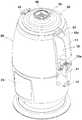
도 1은 본 발명의 사시도.
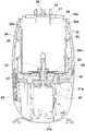
도 2는 본 발명의 분해사시도.
도 3a,3b는 본 발명에 따른 쥬서용구의 설치상태를 보인 단면도.
도 4는 본 발명에 따른 희석용 칼날의 설치상태를 보인 단면도.
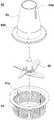
도 5는 본 발명에 따른 쥬서용구를 보인 사시도.
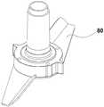
도 6은 본 발명에 따른 희석용 칼날을 보인 사시도.
도 7은 본 발명에 따른 상,하부클러치와 팬을 보인 분해사시도.
도 8은 본 발명에 따른 압력밸브와 투입구커버의 분해사시도.
도 9는 도 8의 결합상태를 보인 단면도.1 is a perspective view of the present invention.
2 is an exploded perspective view of the present invention.
FIGS. 3A and 3B are cross-sectional views showing the installation state of a juicer according to the present invention;
4 is a sectional view showing a state of installation of a dilution knife according to the present invention;
5 is a perspective view showing a juicer tool according to the present invention.
6 is a perspective view showing a diluting blade according to the present invention.
7 is an exploded perspective view showing the upper and lower clutches and the fan according to the present invention.
8 is an exploded perspective view of a pressure valve and a charging port cover according to the present invention.
9 is a cross-sectional view showing the engaged state of Fig.
이하 첨부된 도면에 따라서 본 발명의 기술적 구성을 상세히 설명하면 다음과 같다.DETAILED DESCRIPTION OF THE PREFERRED EMBODIMENTS Hereinafter, the technical structure of the present invention will be described in detail with reference to the accompanying drawings.
본 발명의 쥬서기는 도 1 내지 도 9에 도시되는 바와 같이, 일측 손잡이(11)의 하부로 밸브(12a)에 의해 개폐되는 배출구(12)와, 중앙으로 배치되는 회전축(13)을 구비하는 메인컵(10); 상기 손잡이(11)와 배출구(12)가 끼워지는 개구부(21)와, 메인컵(10)을 가열하는 히터(22) 및 모터(23)와 제어부(24)를 구비하는 몸체(20); 상기 회전축(13)과 모터(23)를 연결시켜주는 상,하부클러치(30)(31); 상기 메인컵(10)에 내장되는 쥬서용구(40); 상기 메인컵(10)의 상부에 장착되어 투입구(51)를 구비하는 컵커버(50); 상기 투입구(51)에 장착되어 압력밸브(60)를 구비하는 투입구커버(70)를 포함하여 구성된 것을 그 기술적 구성상의 기본적인 특징으로 한다.1 to 9, a juicer according to the present invention comprises a
여기서, 본 발명에 따른 쥬서기는 가열기능과 냉각기능을 부여한 것으로, 이러한 본 발명의 쥬서기는 메인컵(10),몸체(20),상,하부클러치(30)(31),쥬서용구(40),컵커버(50),압력밸브(60) 및 투입구커버(70)로 이루어진다.The juicer according to the present invention includes a
상기 메인컵(10)은 몸체(10)의 내부 공간에 분리가능하게 끼워지는 것으로, 이러한 메인컵(10)의 일측에는 손잡이(11)가 설치되고, 메인컵(10)의 일측 하부에는 가공된 재료를 외부로 배출시킬 수 있도록 밸브(12a)에 의해 개폐되는 배출구(12)가 설치되며, 메인컵(10)의 중앙에는 회전축(13)이 구비된다. 이때, 상기 메인컵(10)의 내부에는 쥬서용구(40)가 내장된다. 한편 본 발명에 따르면 재료를 가공한 후, 상기 메인컵(10)을 몸체(20)로부터 분리하지 않은 상태에서 배출구(12)를 통해 가공된 재료를 배출시킬 수 있고, 또한 손잡이(11)를 잡고 몸체(20)로부터 메인컵(10)을 빼낸 상태에서 메인컵(10)을 기울여 가공된 재료를 배출시킬 수 있다.The
상기 몸체(20)는 본 발명에 따른 믹서기의 본체를 구성하는 것으로, 이러한 몸체(20)의 일측에는 메인컵(10)의 손잡이(11)와 배출구(12)를 분리가능하게 끼울 수 있도록 종방향으로 개구부(21)가 형성되고, 몸체(20)에는 필요 시 메인컵(10)을 가열하는 히터(22)가 구비되며, 몸체(20)의 중앙 하부에는 상,하부클러치(30)(31)를 통해 회전축(13)을 구동시키는 모터(23)가 설치되고, 몸체(20)의 전면에는 히터(22)와 모터(23)를 제어하는 제어부(24)가 구비된다. 이때, 상기 제어부(24)는 가공대상물에 따라 히터(22)의 가열온도,시간 등을 제어하고, 또한 상기 제어부(24)는 모터(23)의 구동속도,시간 등을 제어하도록 구성된다.The
본 발명에 따르면 도 3a,3b에서와 같이 상기 몸체(20)의 내부에는 메인컵(10)에 탄력적으로 접촉되는 온도센서(25)가 설치된다. 이때, 상기 온도센서(25)는 제어부(24)에 전기적으로 연결되어 메인컵(10)의 온도를 감지하고, 상기 온도센서(25)에 감지된 신호에 따라 제어부(24)가 과열을 방지하도록 히터(22)를 제어하게 된다.According to the present invention, as shown in FIGS. 3A and 3B, a
본 발명에 따르면 도 3a에서와 같이 상기 몸체(20)에는 내부 공간과 통하도록 제1,2통풍구(20a)(20b)가 형성되고, 상기 하부클러치(31)와 모터(23)의 구동축 하부에는 도 3a와 도 7에서와 같이 제1,2통풍구(20a)(20b)로 바람을 각각 송풍시키는 팬(31a)(23a)이 구비된다. 이때, 상기 모터(23)의 구동시 팬(31a)(23a)이 동시에 구동하고, 팬(31a)(23a)에 의해 발생되는 바람은 제1,2통풍구(20a)(20b)를 통해 메인컵(10)으로 순환되므로, 메인컵(10)을 냉각시켜 과열을 방지할 수 있다.According to the present invention, as shown in FIG. 3A, first and
상기 상,하부클러치(30)(31)는 회전축(13)과 모터(23)를 분리가능하게 연결시켜주는 것으로, 이러한 상부클러치(30)는 회전축(13)의 하부에 구비되고, 하부클러치(31)는 모터(23)의 구동축 상부에 구비된다. 이때, 상기 하부클러치(31)의 외측으로 도 7에서와 같이 팬(31a)이 일체로 형성된다.The upper and
상기 쥬서용구(40)는 메인컵(10)에 분리가능하게 내장되는 것으로, 이러한 쥬서용구(40)는 재료를 갈아 액즙을 만드는 쥬서기용,착즙기용으로 이용된다. 이때, 상기 쥬서용구(40)는 쥬스,토마토,당근,녹즙,마늘,두유,두부 등을 가공하는데 이용된다.The
본 발명에 따르면 도 3a,3b와 도 5에서와 같이, 상기 쥬서용구(40)는 회전축(13)으로 끼워져 고정되는 거름망(41)과, 상기 회전축(13)에 장착되는 쥬서칼날(42)과, 상기 거름망(41)의 상부에 안착되어 재료의 상승을 방지하는 쥬서커버(43)로 이루어진다.According to the present invention, as shown in FIGS. 3A, 3B and 5, the
본 발명에 따르면 도 3a,3b와 도 5에서와 같이, 상기 거름망(41)의 상부 내경에는 받침턱(41a)이 형성되고, 상기 쥬서커버(43)는 상부에서 하부로 그 직경이 커지는 상하가 개방된 테이퍼로 형성되어 상부는 투입구(51)의 하부와 맞대어지며, 상부 일측에는 투입구(51)의 하부 외경에 접촉되는 지지돌기(43a)가 돌출되고, 하부에는 받침턱(41a)에 안착되는 받침원판(43b)이 형성된다.According to the present invention, as shown in FIGS. 3A, 3B and 5, a
상기 컵커버(50)는 메인컵(10)의 상부에 개폐시키는 것으로, 이러한 컵커버(50)의 중앙부에는 메인컵(10)으로 재료를 투입할 수 있도록 투입구(51)가 구비된다.The
본 발명에 따르면 도 1,2 와 도 3b에서와 같이, 상기 컵커버(50)의 일측에는 메인컵(10)의 상단 컬링(10c)에 끼워지는 걸림턱(52)이 형성되고, 상기 컵커버(50)의 타측에는 메인컵(10)의 컬링(10c)에 탄력적으로 체결되는 클램프(53)가 설치된다.According to the present invention, as shown in FIGS. 1, 2 and 3B, a catching
상기 압력밸브(60)는 투입구커버(70)의 중앙부에 설치되는 것으로, 이러한 압력밸브(60)는 메인컵(10)내에 압력이 찰 경우 압력을 자동으로 외부로 배출시키는 역할을 수행한다.The
상기 투입구커버(70)는 컵커버(50)의 투입구(51)를 개폐시키는 것으로, 이러한 투입구커버(70)의 중앙부에는 압력밸브(60)가 설치된다.The
본 발명에 따르면 도 8,9에서와 같이, 상기 투입구커버(70)의 중앙에는 배출공(71)이 형성되고, 상기 압력밸브(60)는 하부가 개방되고 다수의 절개부(61a)와 환턱(61b) 및 이탈방지턱(61c)를 구비하여 배출공(71)에 상하로 이동가능하게 끼워지는 축(61)과, 상기 축(61)의 상부에 형성되어 배출공(71)을 개폐시키는 개폐원판(62)과, 상기 개폐원판(62)의 상부에 매입되는 압력추(63)로 이루어진다.According to the present invention, as shown in FIGS. 8 and 9, a
한편, 본 발명의 다른 실시예에 따르면 도 4와 도 6에서와 같이, 상기 회전축(13)에는 죽이나 반죽을 위한 희석용 칼날(80)이 선택적으로 장착된다. 이때, 상기 희석용 칼날(80)은 죽용,반죽기용으로 이용되는 것으로, 이러한 희석용 칼날(80)은 밀가루반죽 및 죽(쌀,잣,야채 등)을 만들 시 저속으로 휘저어 주고, 또한 희석용 칼날(80)은 재료를 부분적으로 파쇄를 하면서 열을 가해서 끓임 시에 재료가 메인컵(10)에 누는 현상을 방지한다.According to another embodiment of the present invention, as shown in FIGS. 4 and 6, a
이와 같이 구성된 본 발명의 전체적인 작동관계를 상세히 설명하면 다음과 같다.The overall operation of the present invention will now be described in detail.
먼저, 도 3a,3b에서와 같이 몸체(20)에 메인컵(10)을 끼우고, 메인컵(10)의 내부에 거름망(41)과 쥬서칼날(42) 및 쥬서커버(43)로 이루어진 쥬서용구(40)를 도시된 바와 같이 장착한 상태에서 재료를 투입하고, 컵커버(50)와 투입구커버(70)를 닫은 상태에서 제어부(24)를 통해 모터(23)를 구동시키면, 쥬서용구(40)의 쥬서칼날(52)은 설정된 시간과 속도로 구동하면서 투입된 재료를 가공하게 되고, 또한 팬(31a)(23a)이 동시에 구동하면서 메인컵(10)을 냉각시키게 된다. 이때, 필요에 따라서는 쥬서용구(40)의 쥬서커버(43)를 사용하지 않을 수도 있는 것임을 밝혀둔다.First, as shown in FIGS. 3A and 3B, a
재료를 가공한 후, 메인컵(10)을 몸체(20)로부터 분리하지 않은 상태에서 배출구(12)를 통해 가공된 재료를 배출시킬 수 있고, 또한 손잡이(11)를 잡고 몸체(20)로부터 메인컵(10)을 빼낸 상태에서 메인컵(10)을 기울여 가공된 재료를 배출시킬 수 있다.It is possible to discharge the processed material through the
상기와 같은 쥬서 시 필요에 따라서는 제어부(24)를 통해 히터(22)를 제어하여, 투입된 재료를 적정 온도로 가열하면서 쥬서를 수행할 수도 있는 것임을 분명히 밝혀둔다. 이때, 메인컵(10)내에 압력이 찰 경우 압력은 압력밸브(60)를 통해 자동으로 외부로 배출되므로 안정성을 확보할 수 있다.It is clear that the juice may be performed by controlling the
한편, 본 발명을 죽용,반죽기용으로 이용할 경우에는 4에서와 같이 몸체(20)에 메인컵(10)을 끼우고, 메인컵(10)의 회전축(13)에 희석용 칼날(80)을 도시된 바와 같이 장착한 상태에서 재료를 투입하고, 컵커버(50)와 투입구커버(70)를 닫은 상태에서 제어부(24)를 통해 모터(23)를 구동시키면, 희석용 칼날(80)은 설정된 시간과 속도로 구동되면서 투입된 재료를 가공하게 된다.When the present invention is applied to a kneading and kneading machine, the
따라서 이러한 본 발명은 쥬서의 기능뿐만 아니라 히터(22)를 이용한 가열기능과 팬(31a)(23a)을 이용한 냉각기능을 사용할 수 있기 때문에, 구조적으로 동절기에는 재료를 따뜻하게 가열하면서 가공할 수 있고, 하절기에는 재료를 시원하게 냉각하면서 가공할 수 있으므로, 이를 통해 사용자의 편의성을 증대시키는 동시에 상품성을 높일 수 있는 장점이 있다.Therefore, since the present invention can use not only the function of the juicer but also the heating function using the
또한 본 발명은 희석용 칼날(80)을 사용하여 죽용,반죽기용으로도 이용할 수 있는 장점이 있다.Further, the present invention is advantageous in that it can be used for pie or kneader by using the
10 : 메인컵 11 : 손잡이
12 : 배출구 13 : 회전축
20 : 몸체 20a : 제1통풍구
20b : 제2통풍구 21 : 개구부
22 : 히터 23 : 모터
23a : 팬 24 : 제어부
25 : 온도센서 30 : 상부클러치
31 : 하부클러치 31a : 팬
40 : 쥬서용구 41 : 거름망
42 : 쥬서칼날 43 : 쥬서커버
50 : 컵커버 51 : 투입구
60 : 압력밸브 70 : 투입구커버10: main cup 11: handle
12: exhaust port 13:
20:
20b: second ventilation opening 21: opening
22: heater 23: motor
23a: fan 24:
25: temperature sensor 30: upper clutch
31: Lower clutch 31a: Fan
40: Juicer Equipment 41: Filter
42: Juicer blade 43: Juicer cover
50: cup cover 51: inlet
60: Pressure valve 70: Inlet cover
Claims (8)
Translated fromKoreanPriority Applications (1)
| Application Number | Priority Date | Filing Date | Title |
|---|---|---|---|
| KR1020130061144AKR101407018B1 (en) | 2013-05-29 | 2013-05-29 | Juicer device |
Applications Claiming Priority (1)
| Application Number | Priority Date | Filing Date | Title |
|---|---|---|---|
| KR1020130061144AKR101407018B1 (en) | 2013-05-29 | 2013-05-29 | Juicer device |
Publications (1)
| Publication Number | Publication Date |
|---|---|
| KR101407018B1true KR101407018B1 (en) | 2014-06-12 |
Family
ID=51132769
Family Applications (1)
| Application Number | Title | Priority Date | Filing Date |
|---|---|---|---|
| KR1020130061144AExpired - Fee RelatedKR101407018B1 (en) | 2013-05-29 | 2013-05-29 | Juicer device |
Country Status (1)
| Country | Link |
|---|---|
| KR (1) | KR101407018B1 (en) |
Cited By (5)
| Publication number | Priority date | Publication date | Assignee | Title |
|---|---|---|---|---|
| KR20160049862A (en)* | 2014-10-28 | 2016-05-10 | 경남과학기술대학교 산학협력단 | Heat and cool mixer machine |
| WO2018007831A1 (en)* | 2016-07-08 | 2018-01-11 | Kenwood Limited | Valve for a kitchen appliance |
| CN107669086A (en)* | 2017-11-10 | 2018-02-09 | 东台市建东机械制造有限公司 | A kind of Multifunctional juicer |
| JP2020116239A (en)* | 2019-01-25 | 2020-08-06 | タイガー魔法瓶株式会社 | mixer |
| WO2020161508A1 (en)* | 2019-02-04 | 2020-08-13 | KOZADINOS, Athanasios | Cooking appliance for cooling and heating products in a cooking capsule |
Citations (4)
| Publication number | Priority date | Publication date | Assignee | Title |
|---|---|---|---|---|
| US5768978A (en) | 1994-04-28 | 1998-06-23 | Vorwerk & Co. Interholding Gmbh | Food processor comprising a mixing vessel and a drive mechanism for an agitator in the mixing vessel |
| KR20040028866A (en)* | 2004-02-04 | 2004-04-03 | 이유미 | Juicer |
| KR200349211Y1 (en) | 2004-02-10 | 2004-05-04 | 신준범 | A mixer having heater |
| US20090260523A1 (en) | 2008-04-17 | 2009-10-22 | Zheng Peng | Blender |
- 2013
- 2013-05-29KRKR1020130061144Apatent/KR101407018B1/ennot_activeExpired - Fee Related
Patent Citations (4)
| Publication number | Priority date | Publication date | Assignee | Title |
|---|---|---|---|---|
| US5768978A (en) | 1994-04-28 | 1998-06-23 | Vorwerk & Co. Interholding Gmbh | Food processor comprising a mixing vessel and a drive mechanism for an agitator in the mixing vessel |
| KR20040028866A (en)* | 2004-02-04 | 2004-04-03 | 이유미 | Juicer |
| KR200349211Y1 (en) | 2004-02-10 | 2004-05-04 | 신준범 | A mixer having heater |
| US20090260523A1 (en) | 2008-04-17 | 2009-10-22 | Zheng Peng | Blender |
Cited By (8)
| Publication number | Priority date | Publication date | Assignee | Title |
|---|---|---|---|---|
| KR20160049862A (en)* | 2014-10-28 | 2016-05-10 | 경남과학기술대학교 산학협력단 | Heat and cool mixer machine |
| KR101708415B1 (en)* | 2014-10-28 | 2017-02-20 | 경남과학기술대학교 산학협력단 | Heat and cool mixer machine |
| WO2018007831A1 (en)* | 2016-07-08 | 2018-01-11 | Kenwood Limited | Valve for a kitchen appliance |
| GB2552156A (en)* | 2016-07-08 | 2018-01-17 | Kenwood Ltd | Kitchen appliance Lid |
| CN107669086A (en)* | 2017-11-10 | 2018-02-09 | 东台市建东机械制造有限公司 | A kind of Multifunctional juicer |
| JP2020116239A (en)* | 2019-01-25 | 2020-08-06 | タイガー魔法瓶株式会社 | mixer |
| JP7299470B2 (en) | 2019-01-25 | 2023-06-28 | タイガー魔法瓶株式会社 | mixer |
| WO2020161508A1 (en)* | 2019-02-04 | 2020-08-13 | KOZADINOS, Athanasios | Cooking appliance for cooling and heating products in a cooking capsule |
Similar Documents
| Publication | Publication Date | Title |
|---|---|---|
| KR101407018B1 (en) | Juicer device | |
| KR101391972B1 (en) | Multipurpose mixer | |
| JP3198621U (en) | Coffee bean roasting machine | |
| CN112515503A (en) | Multifunctional food processor | |
| KR20090044287A (en) | Coffee roaster | |
| CN111012203A (en) | Multifunctional appliance for cooking | |
| KR102381561B1 (en) | Roasting device of coffee beans using hot air | |
| US20160374515A1 (en) | Removable Blender Pad | |
| KR101408896B1 (en) | Steamer | |
| ES2948837T3 (en) | Food preparation apparatus for cutting food products, grinding accessory and procedure | |
| KR200439650Y1 (en) | Dry Combined Fermenter | |
| JP7152731B2 (en) | coffee bean roasting equipment | |
| KR101664955B1 (en) | rotary-open type damper equipped with a coffee roaster machine | |
| KR101708415B1 (en) | Heat and cool mixer machine | |
| KR101361736B1 (en) | Crushing device | |
| CN219397009U (en) | Baking device and cooking machine | |
| CN211883497U (en) | Multifunctional food processor | |
| WO2009131283A1 (en) | Sludge removing device for frying pot | |
| US20180014696A1 (en) | Non-Integrated Motor Fan in Kitchen Appliance | |
| KR100799519B1 (en) | Table with cold and hot air function | |
| CN212815867U (en) | A refrigeration and fresh-keeping multifunctional cooking pot | |
| CN209074308U (en) | food processor | |
| CN101816338B (en) | Pressure soymilk grinder | |
| CN209749770U (en) | Dried fruit preparation facilities | |
| KR101583799B1 (en) | food processing machine |
Legal Events
| Date | Code | Title | Description |
|---|---|---|---|
| A201 | Request for examination | ||
| PA0109 | Patent application | St.27 status event code:A-0-1-A10-A12-nap-PA0109 | |
| PA0201 | Request for examination | St.27 status event code:A-1-2-D10-D11-exm-PA0201 | |
| A302 | Request for accelerated examination | ||
| PA0302 | Request for accelerated examination | St.27 status event code:A-1-2-D10-D17-exm-PA0302 St.27 status event code:A-1-2-D10-D16-exm-PA0302 | |
| D13-X000 | Search requested | St.27 status event code:A-1-2-D10-D13-srh-X000 | |
| D14-X000 | Search report completed | St.27 status event code:A-1-2-D10-D14-srh-X000 | |
| E902 | Notification of reason for refusal | ||
| PE0902 | Notice of grounds for rejection | St.27 status event code:A-1-2-D10-D21-exm-PE0902 | |
| P11-X000 | Amendment of application requested | St.27 status event code:A-2-2-P10-P11-nap-X000 | |
| P13-X000 | Application amended | St.27 status event code:A-2-2-P10-P13-nap-X000 | |
| E701 | Decision to grant or registration of patent right | ||
| PE0701 | Decision of registration | St.27 status event code:A-1-2-D10-D22-exm-PE0701 | |
| GRNT | Written decision to grant | ||
| PR0701 | Registration of establishment | St.27 status event code:A-2-4-F10-F11-exm-PR0701 | |
| PR1002 | Payment of registration fee | St.27 status event code:A-2-2-U10-U11-oth-PR1002 Fee payment year number:1 | |
| PG1601 | Publication of registration | St.27 status event code:A-4-4-Q10-Q13-nap-PG1601 | |
| LAPS | Lapse due to unpaid annual fee | ||
| PC1903 | Unpaid annual fee | St.27 status event code:A-4-4-U10-U13-oth-PC1903 Not in force date:20170606 Payment event data comment text:Termination Category : DEFAULT_OF_REGISTRATION_FEE | |
| PC1903 | Unpaid annual fee | St.27 status event code:N-4-6-H10-H13-oth-PC1903 Ip right cessation event data comment text:Termination Category : DEFAULT_OF_REGISTRATION_FEE Not in force date:20170606 |