KR101404447B1 - Force estimation for a minimally invasive robotic surgery system - Google Patents
Force estimation for a minimally invasive robotic surgery systemDownload PDFInfo
- Publication number
- KR101404447B1 KR101404447B1KR1020097008933AKR20097008933AKR101404447B1KR 101404447 B1KR101404447 B1KR 101404447B1KR 1020097008933 AKR1020097008933 AKR 1020097008933AKR 20097008933 AKR20097008933 AKR 20097008933AKR 101404447 B1KR101404447 B1KR 101404447B1
- Authority
- KR
- South Korea
- Prior art keywords
- force
- tool
- torque
- measured
- fulcrum
- Prior art date
- Legal status (The legal status is an assumption and is not a legal conclusion. Google has not performed a legal analysis and makes no representation as to the accuracy of the status listed.)
- Active
Links
Images


Classifications
- B—PERFORMING OPERATIONS; TRANSPORTING
- B25—HAND TOOLS; PORTABLE POWER-DRIVEN TOOLS; MANIPULATORS
- B25J—MANIPULATORS; CHAMBERS PROVIDED WITH MANIPULATION DEVICES
- B25J9/00—Programme-controlled manipulators
- B25J9/02—Programme-controlled manipulators characterised by movement of the arms, e.g. cartesian coordinate type
- B25J9/04—Programme-controlled manipulators characterised by movement of the arms, e.g. cartesian coordinate type by rotating at least one arm, excluding the head movement itself, e.g. cylindrical coordinate type or polar coordinate type
- B—PERFORMING OPERATIONS; TRANSPORTING
- B25—HAND TOOLS; PORTABLE POWER-DRIVEN TOOLS; MANIPULATORS
- B25J—MANIPULATORS; CHAMBERS PROVIDED WITH MANIPULATION DEVICES
- B25J13/00—Controls for manipulators
- B25J13/08—Controls for manipulators by means of sensing devices, e.g. viewing or touching devices
- B25J13/085—Force or torque sensors
- A—HUMAN NECESSITIES
- A61—MEDICAL OR VETERINARY SCIENCE; HYGIENE
- A61B—DIAGNOSIS; SURGERY; IDENTIFICATION
- A61B90/00—Instruments, implements or accessories specially adapted for surgery or diagnosis and not covered by any of the groups A61B1/00 - A61B50/00, e.g. for luxation treatment or for protecting wound edges
- A61B90/06—Measuring instruments not otherwise provided for
- A61B2090/062—Measuring instruments not otherwise provided for penetration depth
- A—HUMAN NECESSITIES
- A61—MEDICAL OR VETERINARY SCIENCE; HYGIENE
- A61B—DIAGNOSIS; SURGERY; IDENTIFICATION
- A61B90/00—Instruments, implements or accessories specially adapted for surgery or diagnosis and not covered by any of the groups A61B1/00 - A61B50/00, e.g. for luxation treatment or for protecting wound edges
- A61B90/06—Measuring instruments not otherwise provided for
- A61B2090/064—Measuring instruments not otherwise provided for for measuring force, pressure or mechanical tension
- A—HUMAN NECESSITIES
- A61—MEDICAL OR VETERINARY SCIENCE; HYGIENE
- A61B—DIAGNOSIS; SURGERY; IDENTIFICATION
- A61B34/00—Computer-aided surgery; Manipulators or robots specially adapted for use in surgery
- A61B34/10—Computer-aided planning, simulation or modelling of surgical operations
- A—HUMAN NECESSITIES
- A61—MEDICAL OR VETERINARY SCIENCE; HYGIENE
- A61B—DIAGNOSIS; SURGERY; IDENTIFICATION
- A61B34/00—Computer-aided surgery; Manipulators or robots specially adapted for use in surgery
- A61B34/30—Surgical robots
- A—HUMAN NECESSITIES
- A61—MEDICAL OR VETERINARY SCIENCE; HYGIENE
- A61B—DIAGNOSIS; SURGERY; IDENTIFICATION
- A61B34/00—Computer-aided surgery; Manipulators or robots specially adapted for use in surgery
- A61B34/30—Surgical robots
- A61B34/35—Surgical robots for telesurgery
- A—HUMAN NECESSITIES
- A61—MEDICAL OR VETERINARY SCIENCE; HYGIENE
- A61B—DIAGNOSIS; SURGERY; IDENTIFICATION
- A61B34/00—Computer-aided surgery; Manipulators or robots specially adapted for use in surgery
- A61B34/70—Manipulators specially adapted for use in surgery
- A—HUMAN NECESSITIES
- A61—MEDICAL OR VETERINARY SCIENCE; HYGIENE
- A61B—DIAGNOSIS; SURGERY; IDENTIFICATION
- A61B34/00—Computer-aided surgery; Manipulators or robots specially adapted for use in surgery
- A61B34/70—Manipulators specially adapted for use in surgery
- A61B34/76—Manipulators having means for providing feel, e.g. force or tactile feedback
Landscapes
- Engineering & Computer Science (AREA)
- Health & Medical Sciences (AREA)
- Surgery (AREA)
- Life Sciences & Earth Sciences (AREA)
- Robotics (AREA)
- Biomedical Technology (AREA)
- Animal Behavior & Ethology (AREA)
- Veterinary Medicine (AREA)
- Public Health (AREA)
- Heart & Thoracic Surgery (AREA)
- Medical Informatics (AREA)
- Molecular Biology (AREA)
- Nuclear Medicine, Radiotherapy & Molecular Imaging (AREA)
- General Health & Medical Sciences (AREA)
- Mechanical Engineering (AREA)
- Human Computer Interaction (AREA)
- Manipulator (AREA)
- Force Measurement Appropriate To Specific Purposes (AREA)
- Surgical Instruments (AREA)
Abstract
Translated fromKoreanDescription
Translated fromKorean본 발명은 일반적으로 수술 및 진단 과정을 포함한 최소 침습 수술의 분야에 관한 것이다. 구체적으로, 본 발명은, 특히 최소 침습 도구의 팁에 의해, 그러나 환자의 몸에 들어가는 도구의 접근 포트의 레벨에서조차도, 환자에 가해지는 힘을 결정할 수 있는 힘 추적을 위한 방법 및 시스템에 관한 것이다.The present invention relates generally to the field of minimally invasive surgery including surgical and diagnostic procedures. Specifically, the present invention relates to a method and system for force tracking that can determine the force exerted on a patient, particularly at the level of the access port of the tool that enters the body of the patient, but by the tip of the minimally invasive tool.
최소 침습 중재술(minimally invasive interventions)에는 진단 또는 외과 수술 중에 손상된 외부 조직의 크기를 줄이는 이점이 있다는 것이 잘 알려져 있다. 그 결과 환자의 회복 시간을 더 짧게 할 수 있고, 불편함을 줄이고, 유해한 악영향을 줄이며, 병원비를 낮출 수 있다. 오늘날, 일반적인 외과(surgery), 비뇨기과(urology), 부인과(gynecology), 및 심장병 전문직에서, 복강경 검사(laparoscopic) 기술과 같은 최소 침습 기술에 의해 수행되는 중재술이 증가하고 있다.It is well known that minimally invasive interventions have the advantage of reducing the size of external tissue damaged during diagnosis or surgery. The result is shorter patient recovery times, less discomfort, less harmful effects, and lower hospital costs. Today, in general surgeries, urology, gynecology, and cardiology, interventions performed by minimally invasive techniques such as laparoscopic techniques are increasing.
수동 최소 침습 기술은 일반적으로, 특히 복강경 검사는 수술을 집도하는 외과 의사에 대해 엄격한 요건을 요구한다. 외과 의사는 불편하고 고된 자세로, 시야가 제한되고 덜 능숙하며 촉감 인식이 떨어진 상태에서 수술한다. 이러한 문제 에 부가되는 것은, 외과 의사들은 종종 날마다 몇몇 연속적인 중재술을 해야만 한다는 사실이며, 각각의 중재술은 예를 들어 30분 내지 몇 시간이 걸리기도 한다. 본래부터의 어려움에도 불구하고, 최소 침습 수술은 주민 평균 나이의 상승 및 의료 분야의 비용 압박으로 인하여 수년 안에 더 증가할 것으로 예상되는 경향이 있다.Manual minimally invasive techniques generally require stringent requirements, especially for surgeons operating surgeries. The surgeon is operated in an inconvenient and stubborn posture, with limited vision, less proficiency, and reduced tactile perception. What adds to this problem is that surgeons often have to do several consecutive interventions each day, and each intervention may take, for example, 30 minutes to several hours. Despite the inherent difficulties, minimally invasive surgery tends to be expected to increase further in the years due to rising average age of the population and cost pressures in the medical field.
예를 들어 복강경 검사에서, 외과 의사들은 분명하게도 개복술(laparotomy)만큼이나 움직임이 정교해야되는 것으로 요구받는다. 관절 민첩성을 가진 긴 골간 도구(long shaft instrument)를 조작하는 것은 도구 접근 포트(투관침(trocar))에서, 즉 환자 몸의 절개에서, 받침점(피봇 포인트)을 중심으로 4 자유도로 감소하였다. 무엇보다도 요구된 자세는 종종 지루하고 도구와 조직 사이의 이미 한계에 이른 상호작용 힘의 인지를 감소시키기 때문에 합병증이 일어난다. 그 결과, 외과 의사의 운동 신경 능력은 정상적으로 20-30분 후에는 쇠약해져서 무엇보다도 떨리고, 정확성이 떨어지고 촉감이 감퇴하여 환자에게 위험한 상황이 초래한다. 그러므로 최소 침습 로봇 수술(MIRS)과 같은, 새로운 컴퓨터 및/또는 로봇을 활용한 기술이 부상하고 있다. 이러한 기술들은 중개술의 효율성, 질 및 안전성을 향상을 목표로 하고 있다.For example, in laparoscopy, surgeons are clearly required to be as elaborate in movement as laparotomy. The manipulation of a long shaft instrument with joint agility decreased 4 degrees of freedom about the fulcrum (pivot point) at the tool access port (trocar), i.e. in the incision of the patient's body. First of all, complications arise because the required posture is often tedious and reduces the perception of the interaction force that has already reached the limit between the tool and the tissue. As a result, the surgeon's motor neuron capacity normally declines after 20-30 minutes, causing more trembling, poor accuracy, and reduced touch, resulting in a dangerous situation for the patient. Therefore, new computer and / or robot-based technologies are emerging, such as minimally invasive robotic surgery (MIRS). These technologies aim to improve the efficiency, quality and safety of brokerage.
위와 같은 관점에서, MIRS는 지난 10년 동안 상당히 발전해왔다. 2개의 대표적인 상용 로봇 시스템은 캘리포니아주 서니베일 소재의 인튜이티브 서지컬(Intuitive Sugical)사에서 개발한 상표명 'DA VINCI'로 알려진 시스템이고, 이 시스템은 캘리포니아주, 골레타 소재의 컴퓨터 모션(Computer Motion)사에서 원래 개발한 'ZEUS'로 알려져 있다. 'DA VINCI'라는 이름으로 알려진 시스템은 무엇보다도 US 6,659,939; US 6,837,883 및 동일한 양수인의 다른 특허문헌에 Moll 등에 의해 개시되어 있다. 'ZEUS'라는 이름으로 알려진 시스템은 US, 6,102,850; US 5,762,458; US 5,515,478 및 캘리포니아주 골레타 소재의 컴퓨터 모션사에 양도된 다른 특허문헌에 Wang 등에 의해 개시되어 있다.From this perspective, MIRS has evolved considerably over the past decade. Two representative commercial robotic systems are known as DA VINCI, developed by Intuitive Sugical, Inc. of Sunnyvale, Calif. The system is a computer system known as Computer Motion It is known as 'ZEUS' originally developed by Motion. Systems known as 'DA VINCI' are, above all, US 6,659,939; US 6,837,883 and other patent documents of the same assignee. Systems known as 'ZEUS' are described in US 6,102,850; US 5,762,458; U.S. 5,515,478 and Wang et al. In other patent documents assigned to Computer Motion Company of Goleta, California.
이러한 원격 조종 로봇 시스템은 일반적으로 2차원 또는 3차원 비주얼 피드백만을 사용하여, 수술실에서 직접 또는 원격의 위치에서 외과 중재술을 제어할 수 있게 한다. 어느 경우이든지, 외과 의사가 고된 자세를 취할 필요가 없다. 또한, 이러한 시스템들은 예를 들어 개복술에서와 같이, 외과 의사에게 개방된 조건에서 일할 느낌을 주고, 전술한 고된 자세를 취할 필요가 없다.Such a remotely piloted robotic system generally allows only two or three dimensional visual feedback to be used to control surgical intervention, either directly or at a remote location in the operating room. In either case, the surgeon does not need to take a hard posture. In addition, such systems do not require the surgeon to feel at work in open conditions, as in, for example, laparotomy, and to take the aforementioned stance.
현재 이용 가능한 원격 조종 MIS 시스템은 통상적으로 외과 의사가 로봇(들)에 명령을 내리는 콘솔 상에 진정한 촉감력 피드백(이하 포스 피드백(force feedback)이라 함)을 제공하지 않는다. 그러므로 외과 의사는 기관 및 조직에 가해지는 힘의 진정한 햅틱 느낌(haptic feeling)을 잘 느끼지 못한다. 이러한 시스템에서는, 외과 의사는 비주얼 피드백과 자신의 경험에 의존해야만 하므로 환자내 환경(intra-patient environment)과의 도구의 상호작용이 제한된다. 이와 관련해서, 손으로 하는 MIS 수술에 능숙한 외과 의사가 할 수 있는 것을 컴퓨터가 할 수 있다는 개념에 기초하여 컴퓨터 활용 무센서 포스 피드백 시스템(computer assited sensorless force feedback system)에 관한 연구가 진행되어 왔다. 환언하면, 컴퓨터는 눈(vision)으로 관찰된 변형으로부터 힘을 추정할 수 있을 것이다. 이러한 시도의 일례를, "Force feedback using vision"; Kennddy, C. 및 Desai, J. P.; International Conference on Advanced Robotics; Coimbra, Portuga, 2003에서 볼 수 있다. 이러한 시스템들은 그렇지만 상업적 실용화 상태에는 도달하지 못하고 있다.Currently available remotely controlled MIS systems typically do not provide true tactile feedback (hereinafter referred to as force feedback) on a console where the surgeon commands the robot (s). Therefore, the surgeon does not feel the true haptic feeling of the force applied to the organ and tissue. In such a system, the surgeon has to rely on visual feedback and his experience, thus limiting the interaction of the tool with the intra-patient environment. In this regard, research has been conducted on a computer assisted sensorless force feedback system based on the concept that a computer can do what a surgeon skilled in hand-operated MIS surgery can. In other words, the computer will be able to estimate the force from the deformation observed with vision. An example of such an attempt is "Force feedback using vision"; Kennddy, C. and Desai, J. P .; International Conference on Advanced Robotics; It can be seen in Coimbra, Portuga, 2003. These systems, however, do not reach commercial viability.
이해할 수 있는 바와 같이, 정확한 포스 피드백은, 수술 안전을 보장하고 머신을 활용한 최소 침습 시스템으로 수행되는 수술의 질을 향상시키기 위한 결정적인 특징인 것으로 상정된다. 그러므로 원격 조정 중재술에 있어서는 포스 피드백이 가장 중요한 것으로 여겨진다.As can be appreciated, accurate force feedback is assumed to be a crucial feature for ensuring surgical safety and improving the quality of surgery performed with a minimally invasive system utilizing the machine. Therefore, force feedback is considered to be the most important factor in remote control intervention.
도구 팁 레벨에서, 힘 감지에 의해 예를 들어 기관 및 조직의 촉지(palpation)가 가능한데, 이것은 진단 과정에서나 동맥으로 중요 부위(critical areas)를 식별하는데 매우 바람직하다. 다른 가능성 있는 향상은, 봉합선에 대한 신장 장력(stretching tension)의 제한 및 중재술의 유형 및 특정한 단계에 따라 조직에 가해지는 힘의 제한으로 이루어진다. 실제로, 모션 스케일(motion scale)을 증가시키고, 조작기 모션을 중지시키거나 마스터 디바이스에 대한 포스 피드백을 증가시킴으로써 접촉력을 소정의 임계값 이하로 유지할 수 있다. 또한, 힘 감지는 외과 의사 보조사가 수술 현장에서 기관을 들고 있을 때 내시경 카메라의 시야에 있지 않은 도구를 사용하여 직관적으로 작업할 수 있게 한다.At the tool tip level, force sensing, for example, palpation of the organs and tissues is possible, which is highly desirable in the diagnostic process or in identifying critical areas in the arteries. Other potential enhancements consist of limiting the stretching tension on the seams and the type of intervention and the limitation of the force exerted on the tissue according to certain steps. In practice, the contact force can be kept below a predetermined threshold by increasing the motion scale, stopping the actuator motion, or increasing the force feedback to the master device. Force sensing also allows intuitive operation using tools that are not in the field of view of an endoscopic camera when the surgeon is holding the organ at the surgical site.
접근 포트 레벨에서, 접근 포트의 절개에서 도구에 의해 가해지는 힘을 모니터하여 줄이기 위해서는 힘 감지가 이로울 것이다. 이러한 힘은 복부 압력의 저하, 투관침의 해제 및 상황을 호전시킬 필요성으로 인한 중재술 시간을 야기할 수 있는 절개 상실(incision wear)의 주요 원인이다. 이러한 해로운 힘은 도구 받침점(instrument fulcrum)(피봇 포인트)의 부정확한 위치가 원인인데, 시스템에 의해 결정되고 복부내 압력의 변동으로 의해 변한 바와 같이, 환자 절개와 관련해서 그러나 또한 그 위치선정의 부정확성으로 인한 (로봇) 조작기의 모션 드리프트에 의해서이다. 손으로 하는 중재술에서, 이러한 상실력(wearing forces)은 인간의 능력 때문에 덜 표명되어 절재에서 최적의 피봇 포인트와 관련해서 손의 움직임을 직관적으로 조정한다.At the access port level, force sensing will be beneficial to monitor and reduce the force exerted by the tool in the incision of the access port. This force is a major cause of incision wear which may result in lower abdominal pressure, release of the trocar, and time needed for the condition to improve. This detrimental force is caused by the incorrect location of the instrument fulcrum (pivot point), which, as determined by the system and varied by the variation of pressure in the abdomen, By the motion drift of the (robot) manipulator due to. In hand-held interventions, these wearing forces are less pronounced due to human ability, intuitively adjusting the movement of the hand in relation to the optimal pivot point in the cut.
투관침 해제 문제를 극복하기 위해, 전술한 DA VINCI 시스템은 예를 들어, 도구 삽입/추출 슬라이드의 끝에 조작기 손목에 부착된 투관침을 사용한다. 이 솔루션은 절재 상실의 위험을 줄여주지 못하며 복부 압력의 저하를 향상시키지 못한다.To overcome the trouser release problem, the DA VINCI system described above uses, for example, a trocar attached to the manipulator wrist at the end of the tool insert / extract slide. This solution does not reduce the risk of loss of abdomen and improves abdominal pressure.
투관침 레벨에서의 후자의 문제를 해결하기 위해, 환자의 복부에 접하는 면 상의 로봇 조작기의 받침점 포인트를 자동으로 조절할 수 있는 포스-피드백 적응형 제어기가 개발되어 왔으며, 논문 "Achieving High Precision Laparoscopic Manipulation Through Adaptive Force Control"; Krupa, A. Morel, G. De Mathellin M.; Proceedings of the 2002 IEEE Intern. Conference on Robotics and Automation; Washington D.C. May 2002에 개시되어 있다. 이 방식에서, 로봇의 말단장치(end-effector) 상의 센서는 포스 제어기와 조합하여, 복벽과 함께 받침점을 형성하는, 투관침에 가해지는 측력(lateral force)을 제로(zero) 쪽으로 뚜렷하게 조절하는 데 사용된다. 이 방법 및 시스템은 투관침을 통해 가해지는 도구의 팁에 서의 힘을 결정하지는 못한다. 대신, 도구 팁에서의 상호작용 힘은 무시할 수 있는 것으로 가정한다. 그러므로 이 방법은 환자와의 어떤 다른 접촉점을 갖지 않는 내시경 조작기만으로 만족스럽게 사용될 수 있다.In order to solve the latter problem at the trocar level, a force-feedback adaptive controller capable of automatically adjusting the fulcrum point of the robot manipulator on the abutment surface of the patient has been developed, and the paper entitled " Achieving High Precision Laparoscopic Manipulation Through Adaptive Force Control "; Krupa, A. Morel, G. De Mathellin M .; Proceedings of the 2002 IEEE Intern. Conference on Robotics and Automation; Washington D.C. May 2002. In this manner, the sensor on the end-effector of the robot is used in conjunction with the force controller to visually adjust the lateral force applied to the trocar to zero, which forms a fulcrum with the abdominal wall do. This method and system do not determine the force at the tip of the tool applied through the trocar. Instead, it is assumed that the interaction force at the tool tip is negligible. Therefore, this method can be used satisfactorily only with an endoscope manipulator that does not have any other point of contact with the patient.
논문 "Development of actuated and sensor integrated forceps for minimally invasive robotic surgery"; B.

논문 "A New Robot for force Control in Minimally Invasive Surgery"; Zemiti N., Ortmaier T. et Morel G.; IEEE/RSJ International conference on Intelligent Robots and Systems, Japan, 2004에 도구마다 팁 탑재 센서를 필요로 하지 않는 다른 방법이 개시되어 있다. 이 논문에는 투관침에 설치된 센서와의 원격의 기관-도구 상호작용을 측정할 수 있는 로봇 및 포스 센서 배치에 대해 개시되어 있다. 이 방식에서, 도구 자체에 센서가 장착되어 있지 않으므로 소형화 및 멸균 제약을 낮추게 되지만, 그럼에도 이 솔루션은 멸균을 견뎌낼 수 있는 센서 기구를 가진 변형된 투관침을 필요로 한다. 특허출원 WO 2005/039835에 개시된 바와 같이, MIS를 위해 설계된 다른 방법에서는, 매사츄세츠 워번 소재의 SensAble Technologies사에서 개발한 2개의 PHANTOM? 햅틱 디바이스를 가진 매스터/슬레이브 아키텍처를 사용한다. 이 시스템은 슬레이브 서브시스템에 일체화되고, 효과기 서브어셈블리와 결합하여 도구용 조작기로서 기능하는 제1 PHANTOM 디바이스를 포함하며, 상기 효과기 서브어셈블리는 그래스퍼(grasper), 해부 기구(dissector), 가위(scissor) 등과 같은 최소 침습 도구의 규격품의 도구 팁을 제1 PHANTOM 디바이스에 유지하여 탑재하는 구성으로 되어 있다. 수술 시, 최소 침습 도구는 효과기 서브어셈블리에 장착된 제1 단부와 도구의 동작을 제한하는 외부 받침점을 넘어 위치하는 제2 단부를 가진다. 힘 벡터(fx, fy, fz) 및 도구 팁의 단부에서의 모멘트(τz)의 측정을 제공하기 위해, 주문형 배치의 다양한 스트레인 게이지가 제공된다. 또한, 시스템은 하나의 슬레이브 서브시스템의 제1 PHANTOM 디바이스 및 매스터 서브시스템의 제2 PHANTOM 디바이스를 제어하고 보강하기 위한 응용 프로그램이 내장된 퍼스널 컴퓨터를 포함한다."A New Robot for Force Control in Minimally Invasive Surgery"; Zemiti N., Ortmaier T. et Morel G .; Another method is disclosed in the IEEE / RSJ International conference on Intelligent Robots and Systems, Japan, 2004 that does not require a tip-mounted sensor per tool. This paper discloses a robot and force sensor arrangement capable of measuring remote organ-tool interaction with a sensor mounted on a trocar. In this way, the sensor itself is not equipped with a sensor, which reduces miniaturization and sterilization constraints, but nevertheless the solution requires a modified trocar with a sensor mechanism that can withstand sterilization. In another approach designed for MIS, as disclosed in patent application WO 2005/039835, two PHANTOM? Developed by SensAble Technologies, Woburn, Mass. It uses a master / slave architecture with a haptic device. The system includes a first PHANTOM device integrated into a slave subsystem and in combination with an effector subassembly serving as a manipulator for the tool, the effector subassembly comprising a grasper, a dissector, a scissor ) And the like are held by the first PHANTOM device. In operation, the minimally invasive tool has a first end mounted to the effector subassembly and a second end located beyond an external fulcrum restricting motion of the tool. Various strain gauges in a customized arrangement are provided to provide a measure of the force vector (fx , fy , fz ) and the moment (τz ) at the end of the tool tip. The system also includes a personal computer with an embedded application for controlling and augmenting the first PHANTOM device of one slave subsystem and the second PHANTOM device of the master subsystem.
본 발명의 목적은 투관침 및/또는 도구 팁 장착 센서의 필요 없이 도구 팁에 가해지는 힘을 각각 저렴한 비용 및 효과적인 방식으로 추정할 수 있는 방법 및 시스템을 제공하는 것이다.It is an object of the present invention to provide a method and system that can estimate forces applied to a tool tip in a low cost and effective manner, respectively, without the need for a trocar and / or tool tip mounting sensor.
이 목적을 달성하기 위해, 본 발명은 힘 추정의 방법, 최소 침습 의료 시스템, 특히 이 방법을 수행하도록 적합되어 있는 복강경 검사 시스템을 제안한다. 시스템은 6 자유도(6-DOF 또는 6-축) 힘/토크 센서를 갖는 효과기 유닛을 갖는 조작기, 예를 들어 로봇 조작기를 포함한다. 효과기 유닛은 자신에 장착된 최소 침습 도구를 유지하도록 구성되어 있다. 정상적인 사용에서, 상기 도구의 제1 단부는 상기 효과기 유닛에 장착되어 있으며, 상기 도구의 반대측의 제2 단부는 상기 도구의 동작을 제한하는 외부 받침점(피봇 포인트 운동 제약)을 넘어 위치한다. 일반적으로, 받침점은 환자의 몸 내의 절개, 예를 들어 복벽에 설치된 접근 포트(예를 들어, 투관침) 내에 위치한다. 본 발명에 따르면, 상기 방법은 이하의 단계를 포함한다:To achieve this object, the present invention proposes a method of force estimation, a minimally invasive medical system, and in particular a laparoscopic examination system adapted to perform this method. The system includes an actuator, for example a robot actuator, having an effector unit with a six degrees of freedom (6-DOF or 6-axis) force / torque sensor. The effector unit is configured to hold a minimally invasive tool mounted on it. In normal use, the first end of the tool is mounted to the effector unit and the second end opposite the tool is positioned beyond an external fulcrum (pivot point motion constraint) that limits the motion of the tool. Generally, the fulcrum is located within an incision in the body of the patient, for example, within an access port (e.g., a trocar) installed in the abdominal wall. According to the invention, the method comprises the following steps:
상기 받침점과 관련하여 상기 도구의 위치를 결정하는 단계(본 문맥에서는 특히 도구의 삽입 깊이 또는 센서의 (기준 프레임)과 받침점 사이의 거리를 연속적으로 갱신하는 것을 의미함);Determining the position of the tool in relation to the fulcrum (in this context, in particular the insertion depth of the tool or means of continuously updating the distance between the fulcrum and the reference frame of the sensor);
상기 6 DOF 힘/토크 센서를 이용하여 상기 도구의 상기 제1 단부에 의해 상기 효과기 유닛에 가해지는 힘 및 토크를 측정하는 단계; 및Measuring force and torque applied to the effector unit by the first end of the tool using the 6 DOF force / torque sensor; And
중첩의 원리를 이용하여 상기 결정된 위치, 상기 측정된 힘 및 상기 측정된 토크에 기초하여 상기 도구의 상기 제2 단부에 가해지는 힘의 추정치를 계산하는 단계.Calculating an estimate of the force applied to the second end of the tool based on the determined position, the measured force, and the measured torque using the principle of superposition.
시스템은 6 DOF 힘/토크 센서에 의해 이루어지는 측정을 처리하고 전술한 바와 같은 힘 추정치를 계산하기 위해 도구 위치를 결정하도록 프로그램되어 있는, 표준 컴퓨터, 디지털 시그널 프로세서(DSP), 또는 필드 프로그래머블 게이트 어레이(FPGA)와 같은 프로그래머블 컴퓨팅 디바이스를 포함한다.(DSP), or field programmable gate array (DSP) programmed to determine the tool position to process the measurements made by the 6 DOF force / torque sensor and calculate the force estimate as described above FPGA). ≪ / RTI >
방법 및 시스템은 투관침과 같은 접근 포트를 통해 환자에 침습하는, 도구의 제2 단부, 즉 도구 팁에 의해 환자의 조직 또는 기관에 가해지는 힘을 추정할 수 있게 한다(본 문맥에서는 특히 미세한 부정확성에 의해 영향을 받을 수 있는 값(들)의 결정을 의미함). 진정으로, 후자의 힘은 방법에 의해 추정되는 반대의 힘(반응)(reactio)의 힘(actio)과 동등하다. 이해되는 바와 같이, 이 방법에 의하면, 6-DOF 힘/토크 센서를 포함하는 단일의 센서 유닛만을 필요로 하며 조작기 상에, 즉 환자의 외부에 장착되는 시스템 설계가 가능하다. 편리하게도, 센서 유닛은 효과기 유닛 상의 도구를 위한 연결 인터페이스와 효과기 유닛을 지지하는 조작기의 극단적인 링크/부재 사이의 힘 전송으로 장착된다. 환언하면, 도구의 제1 단부(=장착된 단부)에 의해 효과기 유닛에 가해지는 힘 및 토크를 감지하기 위해 6-DOF 힘/토크 센서가 배치된다.The method and system allow for estimation of the force exerted on the patient's tissue or organ by the second end of the instrument, i.e., the tool tip, which invades the patient through an access port, such as a trocar (particularly in the context of microscopic inaccuracies (S) that can be influenced by the user. Indeed, the latter force is equivalent to the actio of reactivity, which is presumed by the method. As will be appreciated, this method requires only a single sensor unit including a 6-DOF force / torque sensor and is capable of designing a system mounted on an actuator, i.e., external to the patient. Conveniently, the sensor unit is mounted with force transmission between the connecting interface for the tool on the effector unit and the extreme link / member of the actuator supporting the effector unit. In other words, a 6-DOF force / torque sensor is arranged to sense the force and torque applied to the effector unit by the first end (= mounted end) of the tool.
그러므로 본 발명은 도구 팁에 가해지는 힘에 대한 정확한 힘 측정을 달성하기 위해 도구 팁 및/또는 투관침의 레벨에 감지 도구가 제공되어야만 한다는 잘 알려진 일반적 견해를 극복한다. 그러므로 소형화가 어렵고 멸균 제약을 겪어야 했던, 모든 도구의 팁뿐만 아니라 투관침에 제공되어야 하는 고가의 전용 감지 설비를 사용할 필요가 없다. 본 발명의 방법 및 시스템에 따르면, 후자의 제약을 극복하는 동시에, 도구 팁에서의 놀랍도록 정확한 접촉력 추정이 달성될 수 있다.The present invention therefore overcomes the well-known general view that a sensing tool must be provided at the level of the tool tip and / or trocar to achieve an accurate force measurement of the force applied to the tool tip. Therefore, there is no need to use expensive, dedicated sensing equipment that must be provided to the trocar as well as tips of all tools that are difficult to miniaturize and suffer from sterilization constraints. According to the method and system of the present invention, surprisingly accurate contact force estimation in tool tips can be achieved while overcoming the latter constraints.
본 발명의 방법 및 시스템을 수동으로 동작되는 조작기와 연결하여, 또는 더 흔하게는, 로봇 조작기와 연결하여 사용할 수 있음은 물론이다. 방법/시스템은 무엇보다도 최소 침습 로봇 수술 및 진단 시스템과 같은 원격 조정의 의료 시스템에서 포스-피드백 및 자동화된 안전 특성의 구현을 촉진할 수 있다. 예를 들어, 외과 의사용 조작 콘솔의 힘-반사(햅틱) 매스터 아암 상의 촉각 감지뿐만 아니라 도구 팁에 의해 환자의 기관(들) 및 조직(들)에 가해지는 최대의 힘을 제한하기 위한 자동화된 과정을 본 발명의 방법/시스템으로 얻어지는 정보를 이용하여 구현할 수 있다.It will be appreciated that the method and system of the present invention may be used in conjunction with a manually operated actuator, or, more typically, in conjunction with a robotic actuator. The method / system can, among other things, facilitate the implementation of force-feedback and automated safety features in a remotely controlled medical system, such as a minimally invasive robotic surgery and diagnostic system. For example, automated detection of the tactile sense on the force-reflective (haptic) master arm of a surgical operator console as well as the maximum force exerted on the patient's organ (s) and tissue (s) The process can be implemented using information obtained with the method / system of the present invention.
바람직한 실시예에서, 방법은 받침점과 관련해서 도구의 초기 기준 위치를 결정하는 단계를 포함한다. 이 실시예에서, 상기 받침점과 관련해서 상기 도구의 위치를 결정하는 단계는 상기 결정된 초기 기준 위치 및 조작기 모션 정보를 사용하는 연속적인 갱신에 기초한다. 이 유효한 과정은 로봇 조작기의 순기구학(direct kinematics)에 의해 좌표 정보와 같은 공지의 정보의 이점을 취한다.In a preferred embodiment, the method comprises determining an initial reference position of the tool in relation to the fulcrum. In this embodiment, the step of determining the position of the tool in relation to the fulcrum point is based on successive updates using the determined initial reference position and operator motion information. This effective process takes advantage of known information such as coordinate information by the direct kinematics of the robot manipulator.
바람직하게, 방법은 결정된 위치, 측정된 힘 및 측정된 토크에 기초하여, 상기 중첩의 원리를 이용하여 도구의 받침점에서, 예를 들어 투관침에 가해지는 힘의 추정치를 계산하는 단계를 더 포함한다. 받침점에서 가해지는 힘이 반응(reactio)인(부호가 반대인), 절개 레벨에서의 환자의 조직에 가해지는 힘에 대한 지식에 의해, 무엇보다도, 예를 들어 절개 레벨에서 환자의 조직에 가해지는 압박 및 부하를 감소시키기 위해 로봇 제어기에 의해 사용되는, 받침점 좌표의 자동화된 (재)조정이 가능하다. 또한, 접근 포트 레벨에서 가해지는 최대의 힘을 감소시키기 위해 자동화된 과정이 구현될 수 있다.Preferably, the method further comprises calculating an estimate of the force exerted on the trocar, e.g. at the fulcrum of the tool, using the principle of superposition, based on the determined position, the measured force and the measured torque. By knowledge of the force exerted on the patient's tissue at the incision level, where the force exerted at the fulcrum is reactio (opposite sign), above all, for example, Automatic (re) adjustment of fulcrum coordinates, which is used by the robot controller to reduce stress and load, is possible. An automated process can also be implemented to reduce the maximum force applied at the access port level.
바람직하게, 효과기 유닛은 6-DOF 가속도계를 더 구비한다. 이 경우, 방법은 바람직하게,Preferably, the effector unit further comprises a 6-DOF accelerometer. In this case, the method preferably comprises:
- 상기 6-DOF 가속도계를 이용하여 상기 6-DOF 힘/토크 센서에 가해지는 중력 하중 및/또는 동적 하중을 측정하는 단계; 및Measuring gravity load and / or dynamic load applied to the 6-DOF force / torque sensor using the 6-DOF accelerometer; And
- 상기 측정된 힘 및 상기 측정된 토크에서 상기 중력 하중 및/또는 동적 하중을 보상하는 단계- compensating for said gravity load and / or dynamic load at said measured force and said measured torque
를 더 포함한다..
이러한 보상에 의하면, 도구 팁에서 및/또는 받침점 레벨에서 원하는 힘 추정치(들)의 정확성을 향상시킬 수 있다.This compensation can improve the accuracy of the desired force estimate (s) at the tool tip and / or at the fulcrum level.
이롭게도, 방법은 교정 과정을 더 포함하며,Advantageously, the method further comprises a calibration procedure,
상기 교정 과정은 이하의 부가적인 단계를 더 포함한다:The calibration process further includes the following additional steps:
상기 조작기의 작업공간에 걸쳐 분포된 일련의 자세를 통해 상기 효과기 유닛을 통과시키는 단계;Passing the effector unit through a series of postures distributed over the working space of the manipulator;
각각의 자세에 측정된 힘 및 측정된 토크를 기록하는 단계; 및Recording the measured force and the measured torque in each posture; And
상기 기록된 힘 측정치 및 토크 측정치에 기초하여 힘 측정 오프셋 및 토크 측정 오프셋을 결정하는 단계.Determining a force measurement offset and a torque measurement offset based on the recorded force measurement and the torque measurement.
추가의 바람직한 실시예에서, 6-DOF 가속도계가 제공되는 경우, 교정 과정은,In a further preferred embodiment, if a 6-DOF accelerometer is provided,
각각의 자세에 측정된 선형 가속도 및 측정된 각도 가속도를 기록하는 단계; 및Recording the measured linear acceleration and the measured angular acceleration in each posture; And
상기 기록된 선형 가속도 측정치 및 각도 가속도 측정치에 기초하여 선형 가속도 측정치 오프셋 및 각도 가속도 측정치 오프셋을 결정하는 단계Determining a linear acceleration measurement offset and an angular acceleration measurement offset based on the recorded linear acceleration measurement and the angular acceleration measurement;
를 더 포함한다..
교정 과정에 의하면 센서들에 의해 제공되는 측정 신호에서의 (전기적) 오프셋 및 추가의 유용한 시스템 파라미터를 결정할 수 있으며, 이에 대한 지식으로 원하는 힘 추정치(들)의 정확성을 더욱 향상시킬 수 있다.The calibration procedure can determine (electrical) offsets and additional useful system parameters in the measurement signal provided by the sensors, and with this knowledge, the accuracy of the desired force estimate (s) can be further improved.
측정 신호 노이즈를 감소시키기 위해, 방법은 이롭게도 상기 추정된 힘을 계산하기 전에 상기 6-DOF 힘/토크 센서에 의해 측정된 힘 및 토크 데이터에 (예를 들어 비선형 확장 칼만 공식과 반대의 기본적인 사항에 따라) 선형 칼만 필터를 적용하는 단계 및 상기 추정된 힘(들)이 계산된 후에, 상기 계산된 힘 추정치에 선형 칼만 필터를 적용하는 단계를 더 포함한다. 많은 이용 가능한 필터 형태 중에서, 측정된 성분에서 신호 노이즈를 제거하는데 있어서 기본적인 선형 칼만 필터가 간단하고 신뢰성 있는 고속 필터인 것으로 알려져 있다.In order to reduce the measurement signal noise, the method advantageously involves adding to the force and torque data measured by the 6-DOF force / torque sensor (for example, the basic principle opposite to the nonlinear extended Kalman formula Applying a linear Kalman filter to the calculated force estimate after the estimated force (s) is calculated, and applying a linear Kalman filter to the calculated force estimate. Among the many available filter types, the basic linear Kalman filter is known to be a simple and reliable high-speed filter in removing signal noise from the measured components.
가속도계가 제공되는 경우, 방법은 바람직하게,If an accelerometer is provided,
- 상기 6-DOF 힘/토크 센서에 의해 측정된 힘 및 토크 데이터에 대해 그리고 상기 6-DOF 가속도계에 의해 측정된 선형 및 각도 가속도 데이터에 대해 1차 선형 칼만 필터를 적용하는 단계;Applying a first order linear Kalman filter to the force and torque data measured by said 6-DOF force / torque sensor and to linear and angular acceleration data measured by said 6-DOF accelerometer;
- 상기 1차 선형 칼만 필터의 적용 후 중력 하중 및 동적 하중으로 인한 교란을 보상하는 단계; 및Compensating for disturbances due to gravity and dynamic loads after application of said first linear Kalman filter; And
- 상기 보상된 힘 및 토크 데이터에 2차 선형 칼만 필터를 적용하는 단계- applying a second order linear Kalman filter to the compensated force and torque data
를 포함할 수 있다.. ≪ / RTI >
모든 칼만 필터는 각각의 힘/토크 및 가속도 성분에 있어서 필터 고유의 응답-지연을 동일하게 발생해야만 한다. (가속도 신호가 힘/토크 측정치보다 노이즈가 더 심하여) 보상 후에도 힘 성분 추정치에 과도한 노이즈가 있는 경우에는, 교란 보상 후 2차 필터가 양호하다.Every Kalman filter must produce the same response-delay inherent in the filter for each force / torque and acceleration component. If there is excessive noise in the force component estimate after compensation (because the acceleration signal is more noise than the force / torque measurement), the second filter after disturbance compensation is good.
1차 필터는 보상 동안 노이즈-유도의 왜곡(falsification)을 감소시키는 반면, 2차 필터에 의해서는 보상 결과의 평활화가 가능하다.The first filter reduces the noise-induced falsification during compensation, while the second filter allows smoothing of the compensation result.
바람직하게, 상기 칼만 필터, 각각의 상기 1차 칼만 필터 및/또는 상기 2차 칼만 필터는 직렬이며, 프로세스 노이즈 공분산 파라미터가 높은 값에, 바람직하게는 0.1 내지 1의 범위에 설정되어 있는 제1 선형 칼만 필터 스테이지, 및 프로세스 노이즈 공분산 파라미터가 낮은 값에, 바람직하게는 0.001 내지 0.1의 범위에 설정되어 있는 제2 선형 칼만 필터 스테이지를 가진다. 주어진 측정 노이즈 공분산에서, 직렬의 필터 구성에 의하면, 주어진 노이즈 감소 용량에 있어서, 단일의 스테이지 필터와 비교해 볼 때 전체적인 응답-지연이 더 낮을 수 있다.Preferably, the Kalman filter, each of the first and second Kalman filters and / or the second Kalman filter is in series, and the process noise covariance parameter is set to a high value, preferably in the range of 0.1 to 1, A Kalman filter stage, and a second linear Kalman filter stage in which the process noise covariance parameter is set to a low value, preferably in the range of 0.001 to 0.1. For a given measured noise covariance, the series filter configuration can result in lower overall response-delay for a given noise reduction capacity compared to a single stage filter.
이해되는 바와 같이, 시스템은 센서 없는 최소 침습 도구와 함께 사용되는데 적합되어 있다. 바람직하게는 자기-기반의 에어 밸브를 가지는 그리고 특별하게는 플라스틱 캡을 갖지 않는, 센서 없는 투관침을 더 이롭게 포함한다. 또한 시스템은 가스 탭을 갖지 않는 투관침을 이롭게 포함하고 이 투관침은 플라스틱 재료를 주재료로 해서 바람직하게 만들어져서 중량을 줄일 수 있다.As will be appreciated, the system is suitable for use with sensorless minimally invasive tools. Advantageously a sensorless trocar with a preferably self-based air valve and in particular without a plastic cap. The system also advantageously includes a trocar without a gas tap, which can be advantageously made from a plastic material as a main material, thereby reducing weight.
시스템은 프로그래머블 컴퓨팅 디바이스에 의해 저장되는 소프트웨어 프로그램을 포함할 수 있으며, 상기 소프트웨어 프로그램은, 프로그래머블 컴퓨팅 디바이스에서 운용될 때 상기 방법의 전술한 실시예들 중 임의의 실시예의 모든 단계를 수행하기 위한 프로그램 코드를 포함한다. 본 발명은 또한, 상기 프로그램 코드가 상기 프로그래머블 컴퓨팅 디바이스에서 운용되거나 로드되어 있을 때, 상기 프로그래머블 컴퓨팅 디바이스로 하여금 상기 방법의 전술한 실시예들 중 임의의 실시예의 모든 단계를 수행하게 하는, 머신-판독 가능 저장 매체 상에 저장되어 있는 프로그램 코드를 포함하는 소프트웨어 프로그램 제품에 관한 것이다.The system may include a software program stored by a programmable computing device that when executed on a programmable computing device includes program code for performing all steps of any of the foregoing embodiments of the method . The present invention also provides a machine-readable storage medium having stored thereon machine-readable instructions that cause the programmable computing device to perform all of the steps of any of the preceding embodiments of the method when the program code is being operated or loaded on the programmable computing device And more particularly to a software program product comprising program code stored on a computer readable storage medium.
원칙적으로 출원된 바와 같은 본 특허출원이 본 명세서에 첨부된 청구의 범위에 정의된 바와 같은 발명에 관한 것이지만, 본 특허출원이 다른 발명의 정의에 대한 지지를 포함하며, 이것은 예를 들어 본 출원의 보정된 청구의 범위의 요지와 같이 또는 분할 및/또는 연속 출원에서의 청구의 범위의 요지와 같이 청구될 수 있다는 것을 당업자는 용이하게 이해할 수 있을 것이다. 이러한 요지는 여기에 개시된 임의의 특징이나 특징들의 조합에 의해 정의될 수 있다.While this patent application, as filed in principle, is directed to an invention as defined in the claims appended hereto, the present patent application includes support for the definition of another invention, Those skilled in the art will readily appreciate that the invention may be claimed as claimed in the appended claims or as outlined in the division and / This spirit can be defined by any feature or combination of features disclosed herein.
본 발명의 다른 상세한 설명 및 이점은 첨부된 도면을 참조하되 제한하려는 의도가 아닌, 이하의 상세한 설명으로부터 분명하게 될 것이다.Other details and advantages of the invention will become apparent from the following detailed description, which is intended to be illustrative but not restrictive of the appended drawings.
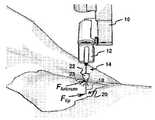
도 1은 본 발명의 양호한 실시예에 따른 최소 침습 의료 시스템용 로봇 조작 기의 사시도이다.1 is a perspective view of a robot manipulator for a minimally invasive medical system according to a preferred embodiment of the present invention.
도 2는 받침점 힘 및 팁 힘을 나타내기 위해, 최소 침습 도구의 팁이 환자에 삽입되고, 최소 침습 도구의 반대 단부가 도 1의 로봇 조작기의 효과기 유닛에 장착되어 있는, 최소 침습 도구의 부분 사시도이다.Figure 2 is a partial perspective view of a minimally invasive tool in which the tip of the minimally invasive tool is inserted into the patient and the opposite end of the minimally invasive tool is mounted to the effector unit of the robot manipulator of Figure 1, to be.
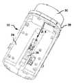
도 3은 도 2의 효과기 유닛에 제공된 힘/토크 및 가속 센서의 기준 좌표계를 설명하는, 효과기 유닛의 확대 사시도이다.Figure 3 is an enlarged perspective view of the effector unit, illustrating the reference coordinate system of the force / torque and acceleration sensor provided in the effector unit of Figure 2;
도 4는 직렬연결된 선형 칼만 필터의 개략 블록도이다.4 is a schematic block diagram of a series connected linear Kalman filter.
도 5는 본 발명에 따른 방법을 실행하기 위한 소프트웨어 아키텍처의 개략 블록도이다.5 is a schematic block diagram of a software architecture for implementing the method according to the present invention.
도 6은 도 5의 아키텍처의 주작업(main task)(FSS 작업)의 상태 변환도이다.Figure 6 is a state transition diagram of the main task (FSS task) of the architecture of Figure 5;
도 7은 도 6의 APPLICATION_LOADS_EVALUATION 상태 동안 주기적으로 수행되는 프로그램 단계의 시퀀스에 대한 흐름도이다.7 is a flowchart of a sequence of program steps performed periodically during the APPLICATION_LOADS_EVALUATION state of FIG.
도 8은 도 6의 APPLICATION_LOADS_EVALUATION 상태 동안 주기적으로 수행되는 프로그램 단계의 다른 시퀀스에 대한 흐름도이다.8 is a flowchart of another sequence of program steps performed periodically during the APPLICATION_LOADS_EVALUATION state of FIG.
시스템 구성요소 및 기계적 구성System components and mechanical configuration
도 1은 본 발명에 따른 최소 침습 의료 시스템의 주요 기계적 구성요소를 도시하고 있다. 시스템은 일반적으로 도면부호 10으로 표시된 로봇 조작기를 포함한다. 로봇 조작기(10)의 플랜지에는 효과기 유닛(12)이 연결되어 있다. 도 1에 도시된 바와 같이 효과기 유닛에는 제1 단부(16)와 함께 최소 침습 도구(14)가 장착 되어 있다. 도구(14)는 팁(20)을 가지는 긴 샤프트(18)를 포함하며, 상기 팁(20)은 도구(14)의 제2 단부를 형성한다. 이 팁(20)에서, 도구(14)는 정상적으로 특정한 툴, 예를 들어 그래스퍼, 가위, 후크, 응고제(coagulator) 등을 포함한다. 로봇 조작기(10) 자체는 효과기 유닛(12)을 위치시키고 지향시키기 위한 PRP-RRR 조인트 배치에 의해 6 자유도(DOF)를 제공하며, 효과기 유닛(12)은 도구(14)의 세로 샤프트 축과 일치하는 로봇 조작기(10)의 6번째 DOF를 중심으로 최소 침습 도구(14)를 회전시키기 위한 선두 회전(R) 조인트에 장착되어 있다. 이해되는 바와 같이, 로봇 조작기(10)는 효과기 유닛(12)의 움직임에 의해 외과 의사의 손의 움직임을 그대로 따라할 수 있는 6축 위치선정 및 지향 디바이스를 제공한다.Figure 1 shows the main mechanical components of a minimally invasive medical system according to the present invention. The system includes a robot manipulator, generally indicated at 10. The
도 2는 최소 침습 의료 과정을 수행하기 위한 수술 위치에서 로봇 조작기(10)의 효과기 유닛(12)에 장착되어 있는 도구(14)를 도시하고 있다. 도 2에 점선으로 도시되어 있는 바와 같이, 도구(12)의 샤프트(18)는 환자의 몸에, 예를 들어 환자의 복부에 일부분이 삽입된다. 도구는 이하 투관침(22)이라 칭할 접근 포트를 통해 슬라이딩하면서 관통한다. 도구(14)의 제1 단부, 즉, 팁(20)은 환자의 복벽에서의 절개에 삽입되어 거기에 고정된 투관침(22)에 의해 형성된, 도면부호 23에서 십자 형상의 파선으로 표시된 받침점(피봇 포인트라고도 함)을 넘어 위치한다.Figure 2 shows the
정상적인 사용에서, 받침점은 3개의 축(예를 들어, 2개의 직교 피봇 방향 및 도구를 중심으로 하는 하나의 방향, 즉, 이하에 정의된 SRF에서의 Z축)을 중심으로 회전 가능하되 (예를 들어 이하에 정의된 SRF에서의 받침점 22-Z의) 관통축만을 따 라 도구(14)의 변환이 가능한 운동학적 제약이다. 받침점은 접근 포트에 의해, 예를 들어 투관침(22)에 의해 및/또는 절개가 제공되는 환자의 조직, 예를 들어 환자의 복벽에 의해 정의된다.In normal use, the fulcrum is rotatable about three axes (e.g., one orthogonal pivot direction and one direction about the tool, i.e., the Z axis in the SRF defined below) For kinematic constraints, it is possible to transform the tool (14) only along the through axis of the fulcrum (22-Z) in the SRF defined below. The fulcrum is defined by the access port, for example by the
도 2는 개략적으로 2개의 힘


도면에 도시되지는 않았지만, 시스템은 즉, 하드웨어, 예를 들어 하나 이상의 로봇 조작기(10)를 동작시키기 위한 소프트웨어로 프로그램되어 있는 메인 컴퓨터의 형태로 된 조작기 제어기를 더 포함한다. 또한, 오퍼레이터, 즉 외과 의사는 힘 반사 매스터 아암(force reflection master arm)으로 원격-조정을 위한 커맨드 콘솔, 즉, 포스-피드백을 위한 햅틱 인터페이스를 사용하여, 조작기 제어기를 통해 로봇 조작기(10)에 명령한다. 이해되는 바와 같이,

도 3은 기계적으로 단단하게 도구(14)(도 3에 도시되지 않음)의 제1 단부(16)를 지지하도록 배치되어 있는 효과기 유닛(12)의 확대도를 도시하고 있으며 특정한 유형의 도구를 활성화시키기 위한 액추에이팅 수단 및 도구(14)를 시스템에 전기적으로 연결하기 위한 신호 및 전력 연결 수단을 더 구비한다. 효과기 유닛(12)은 상기 액추에이팅 수단 및 상기 연결 수단뿐만 아니라 도구(14)(도시되지 않음)의 제1 단부(16)에서의 어댑터가 단단하게 연결될 수 있는 소켓(26)을 포함하는 단단한 주요 몸체(24)를 포함한다. 그 이면의 단부에서, 주요 몸체(24)는 12-DOF(즉, 12축) 힘/토크의 감지판 및 가속 센서(30)에 단단하게 고정되어 있는 연결 플랜지(28)를 포함하며, 상기 가속 센서(30)를 이하에서는 F/TAS(30)로 칭한다. F/TAS(30)는, 3개의 직교 축 상에서의 힘 및 토크를 감지하기 위한, 이하에서 F/T 센서라 칭할, 6-DOF 힘/토크 센서, 및 3개의 직교 축을 중심으로 선형 가속 및 각도 가속을 감지하기 위한 내장형 6-DOF 가속도계를 포함하는 단일의 센서 유닛으로 구성될 수 있다. 대안적으로, 적절하게 관련된 별도의 6-DOF 가속도계를 가지는 6-DOF 힘/토크 센서도 사용될 수 있다. F/FAS(30)는 도 1에 도시된 바와 같이, 로봇 조작기(10)에 차례로 단단하게 고정되어 있다. 서술된 F/TAS(30) 대신에, 6-DOF F/T 센서만을 포함하는 센서 유닛(가속도계가 아님)이 사용될 수 있다. 후자의 경우, 가속 성분은 관절 위치를 사용하여 직접적인 운동 계산에 의해 얻어진 단부-효과기(예를 들어, 효과기 유닛(12))의 위치 좌표에 대한 2차 도함수를 사용하 여 결정될 수 있다. 이하에 서술되는 바와 같은 동적 하중의 계산은 그러므로 가속도계 없이 달성될 수 있다. 중력의 효과도 또한 가속도계 없이 계산될 수 있다는 것에 주목해야 하는데, 왜냐하면, 중력 벡터는 알려져 있고 F/T 센서에 부착된 페이로드(payload)의 중력의 방향 및 중심은 결정될 수 있기 때문이다.Figure 3 shows an enlarged view of the
도 3은 3개의 직교 축 X, Y, Z을 가지는, F/TAS(30)의 직각 기준 좌표계를 도시하고 있으며, 이하 SRF(센서 기준 프레임)이라 칭한다. 이해되는 바와 같이, SRF에서, F/TAS(30)에서 F/T 센서의 6 DOF는 X, Y, Z 힘 성분 각각에 대한 3 DOF 및 X, Y, Z 축 각각을 중심으로 하는 모멘트(토크 값)에 대한 3 DOF에 대응한다. 별도의 6-DOF 가속도계가 F/TAS(30)을 제공하기 위한 6-DOF F/T 센서에 부착되어 있는 경우, 가속도계의 기준 좌표계는 F/T 센서의 기준 좌표계와 바람직하게 일치한다. 그렇지 않으면, 이러한 2개의 직각 좌표들 사이의 추가의 변환은 이하에 설명되는 계산에서 추가될 것이다. 도 1 내지 도 3에 도시된 실시예에서, 12축 F/TAS(30)는 내장형 6-DOF 가속도계를 포함한다. 가속도계의 6 DOF는 도 3에 도시된 SRF에서, X, Y, Z 축을 따르는 선형 가속도 성분 및 상기 X, Y, Z 축 각각을 중심으로 하는 각도 가속 성분에 대응한다.3 shows a rectangular reference coordinate system of the F /
이해되는 바와 같이, 효과기 유닛(12)은 F/TAS(30)의 감지판에 단단히 고정되어 있고 장착된 도구(14)(도 2 참조)의 세로(샤프트) 축이 F/TAS(30)의 SRF의 하나의 축, 바람직하게는 도 3에서 보이는 바와 같이 Z 축과 동일 선상에 있다. 그렇지 않으면, 추가의 변형이 이하에 설명되는 계산에서 추가될 것이다.As will be appreciated, the
주요 교란 소스 및 그것의 분석Analysis of the main disturbance source and its
이 장에서는 도구 팁(20)에서의 원하는 힘의 추정치에 영향을 주는 주요 교란 소스에 대해 논의할 것이며, 시스템은 도 1 내지 도 3에 제시되어 있다.In this section, we will discuss the major disturbance sources that affect the estimate of the desired force in
센서 오프셋, 전기 노이즈 및 온도 드리프트와 같은 내재적 F/T 센서 교란 외에, 본 시스템과 함께 다른 공지의 힘 감지 시스템과는 반대인(예를 들어, 도구 팁에 장착된 F/T 센서를 사용하여), 일련의 추가의 교란 및 마스킹 요인을 고려해야 한다. 측정된 힘 및 모멘트 정보와 관련해서는 주로 이하가 같이 있다:In addition to intrinsic F / T sensor disturbances such as sensor offsets, electrical noise, and temperature drift, in addition to other known force sensing systems with the present system (e.g., using F / T sensors mounted on tool tips) , A series of additional perturbations and masking factors should be considered. The following are mainly related to the measured force and moment information:
- F/T 센서에 가해지는 정적 및 동적 하중: 중력으로 인한 정적 하중(조작기 장착 F/T(30)에 부착된 질량의 중량), F/T 센서에 부착된 페이로드의 속도 및 가속도로 인한 동적 하중;- Static and dynamic loads applied to the F / T sensor: Static load due to gravity (weight of the mass attached to the actuator F / T (30)), speed and acceleration of the payload attached to the F / T sensor Dynamic loading;
- 최소 침습 의료 과정과 관련된 교란 소스: 투관침 가스 탭 및 에어 밸브로 인한 관통 및 추출 방향에서의 투관침 마찰력, 투관침 가스 탭으로 인한 피봇에 대한 저항, 복부 흡입 압력의 변동으로 인한 받침점(23)(피봇 포인트)의 변형, 받침점(23)의 부정확한 정의, 움직이는 동안의 조작기(10)의 부정확성으로 인한 받침점(23)의 변형.- sources of perturbation associated with minimally invasive medical procedures: trocar friction in penetration and extraction direction due to the trocar gas tap and air valve, resistance to pivot due to trocar gas tap, fulcrum (23) due to fluctuations in abdominal suction pressure Point), an incorrect definition of
투관침 마찰에 의해 생기는 교란력(distrubing force): 투관침(22)은 관통/추출 축을 따라 마찰을 생성한다. 마찰 크기는, 플라스틱 캡 상실, 도구 샤프트(18)의 재료 및 관주 수분(irrigation water) 및 복강내 점성액에 의한 그 내부 윤활(internal lubrication)에 대하여, 투관침(22)에서 사용된 에어-밸브의 유형(예를 들어, 자기 유형, 스프링-기반 유형 또는 플라스틱 멤브레인 유형)에 좌우된다. 실험실 실험에 따르면, 자기 및 스프링-기반의 에어-밸브에 의해 생긴 마찰은 0.5N - 0.9N의 범위에서 쿨롱 마찰에 의해 근사될 수 있으며 윤활 조건에 의존하지 않는다. 실제로, 스프링-기반의 에어-밸브 마찰은 그 상실에 약간 의존하며, 약 0.3N만큼 자기 에어-밸브 마찰보다 더 높다. 플라스틱 멤브레인 에어-밸브 및 플라스틱 캡은 쿨롱 마찰을 일으키지만 도구 방향을 반대로 할 때는 임펄스형 반응력도 일으킨다. 이 반응 성분은 모션 방향과는 반대이며 주로 플라스틱 칼라 리버설(plastic collar reversal)에 의해 야기된다. 멤브레인 및 캡 마찰은 멤브레인 절단 기하학적 구조 및 재료의 유형에 따라 다르지만, 도구의 움직임을 통한 중재술 시간과 함께 증가하는 투관침(22)의 윤활에 의해 감쇠된다. 표준 투관침을 사용하는 건조한 실험실 실험에서는, 플라스틱 캡이 1N - 1.5N 범위의 쿨롱 마찰을 일으키고, 플라스틱 멤브레인 에어-밸브는 6N - 10N 범위의 쿨롱 마찰을 제공한다. 또한, 마찰 크기는 관통 및 추출 방향과 관련해서 비대칭인 것으로 알려져 있다. 플라스틱 멤브레인 밸브에 있어서, 관통 방향으로 더 작은 마찰 크기가 관찰되었다. 그러므로 투관침(22)에서의 관통 및 추출 마찰을 가능한 많이 줄이기 위해서는, 가능한 플라스틱 캡이 없는 자기-기반의 에어-밸브가 바람직하다.Distrubing force caused by trocar tip friction: The
투관침 가스 탭에 의해 생기는 교란력: 몇몇 유형의 투관침은 흡입 가스용 캡을 갖는다. 탭 및 연결된 가스관은 투관침(22)을 피봇팅할 때 장애물의 역할을 하고, 그 결과 피봇 방향과는 반대의 교란 저항력이 생긴다. 이 힘의 크기는 복벽의 탄성계수(stiffness)에 의존하며 실험실 실험에 따르면 일반적으로 2N과 5N 사이이다. 그러므로 가스 탭을 구비한 투관침의 사용은 본 시스템에서는 회피해야만 한다.Disturbances caused by the trocar gas tap: Some types of trocar have a cap for the suction gas. The tabs and associated gas pipes serve as obstacles when pivoting the
투관침 용량에 의해 생기는 교란력: 다용도의 투관침은 일반적으로 30g 내지 80g의 경량이고, 가능한 스테인리스 강철로 만들지만 일부는 플라스틱으로 되어 있다. 가스 탭을 구비한 투관침은 원통형 리저버를 가지며 100g 내지 180g의 중량이다. 투관침 무게는 중력 벡터와 관련해서 투관침(22)의 방향에 따라, SRF에서 교차하는 X 및 Y 축을 따라 교란력으로서 인지될 수 있다. 그러므로 플라스틱 부분을 가진 경량의 투관침이 제안된 시스템에서 바람직하다.Disturbance caused by trocar dose: The multipurpose trocar is generally made of 30 to 80 grams of lightweight, possibly stainless steel, but some are made of plastic. The trocar with gas tab has a cylindrical reservoir and weights from 100 g to 180 g. The trocar weight can be perceived as disturbance along the X and Y axes intersecting in the SRF, depending on the orientation of the
낮은 복강내 압력에 의해 생기는 교란력: 정상적인 복강경 검사 조건에서, 낮은 복강내 압력의 경우, 투관침 마찰 크기는 복벽에 의해 제공되는 저항보다 높을 수 있다. 이 경우, 도구 관통 또는 추출은 투관침(22)을 복벽 신장이 투관침 마찰을 극복하는 지점에 대해 안쪽 또는 바깥으로 이동시킬 수 있다. 부정적인 악영향은 먼저, 받침점(23)의 위치가 복벽과 관련해서 변한다는 것이고, 이에 의해 피봇팅 동안의 교란 하중이 도구와 복벽과의 상호작용으로 인해 증가한다는 것이며, 두 번째로, 스프링형 하중(투과침 마찰과 동등한 최대값을 가짐)이 도구의 모션과 반대의 방향으로 가해진다는 것이다. 이러한 교란력을 회피하기 위해서는, 복강내 압력을 계속해서 모니터해서 유지하는 것이 바람직하다. 감압(depressurization)의 경우에는, 조작기 제어기에서의 받침점 위치를 조정하는 것과 같이, 적절한 행동을 취하기 위해 경고가 발동된다.Disturbance caused by low intraperitoneal pressure: Under normal laparoscopic conditions, for low intraperitoneal pressure, the size of the trocar can be higher than the resistance provided by the abdominal wall. In this case, tool penetration or extraction may cause the
받침점 위치의 결정의 부정확성으로 인한 교란력: 손으로 하는 복강경 검사 외과 수술에서, 외과 의사는 자연스럽게 도구를 미러 틸팅 저항 포인트와 관련해서 이동시키며, 이 포인트는 투관침(22)의 내부에서, 복벽의 가장 강한 층의 높이를 중심으로 해서 위치하는 이상적인 받침점(23)(피봇 포인트)이다. 받침점(23)과 관련해서 어떤 특정적으로 설계된 기계적 컴플라이언스(compliance) 없이, 도구(14)를 다루기 위한 로봇 조작기(10)를 사용할 때, 받침점 위치는 적절한 과정에 의해 결정되어야 하고 조작기 제어기에 의해 조정되어야 한다. 받침점 위치가 부정확하게 형성되면, 도구(14)의 피봇팅은 도구 팁(20) 및/또는 받침점(23)에서의 원하는 힘/토크 값을 마스킹할 수 있는 복벽과의 상호작용력을 발생한다. 이러한 마스킹 힘은 받침점 위치 부정확성의 크기에 따라 증가한다. 또한, 이러한 부정확성은 절개의 상실을 생기게 하고, 이것은 투관침(22)의 해제를 야기할 수 있고, 차례로 복부 압력의 저하를 일으키며 이에 의해 필요한 상황의 회복으로 인해 불필요하게 중재술 시간을 증가시킨다.Disturbance due to inaccurate determination of fulcrum location: In a hand-operated laparoscopic surgical operation, the surgeon naturally moves the tool in relation to the mirror tilting resistance point, which points in the interior of the
받침점(23)의 위치의 정의 정확성(definition accuracy)은 그 위치를 식별하는데 사용되는 과정에 의존할 뿐만 아니라 로봇 조작기(10)의 정적 정확성 및 동적 정확성에도 의존한다. 본 발명의 출원에서는, 절개 치수 및 복벽의 탄력을 고려하여 전체 받침점과 조작기 정확성의 +/-2.5㎜ 추정치를 수용할 만하다. 실험적 설정에 따르면, 받침점(23)에 관한 정의 부정확성은 투관침(22)의 레벨에서 2N-10N의 교란을 일으킬 수 있다.The definition accuracy of the position of the
그 결과, 투관침(22)의 유형의 적절한 선택은 가스 탭 교란을 회피할 수 있게 하고 0.6N인 통상적인 인간의 손 감도의 레벨까지 도구 샤프트(18)의 축을 따라 마찰 및 중량 교란을 감소시킨다. 초기의 받침점 정의에서의 압력과 관련해서 복강내 압력을 실시간 모니터함으로써, 흡입 조건의 변화로 인한 진정한 받침점 위치 의 변동을 검출할 수 있다. 그렇지만, 접근 포트 레벨(즉, 받침점(23) 또는 피봇 포인트)에서의 교란력은, 받침점(23)의 부정확한 정의 및 조작기(10)의 모션 부정확성으로 인해, 이하에 설명되는 제안된 방법을 통해 실시간으로 확인될 수 있다.As a result, the proper selection of the type of
제안된 방법 및 시스템은 당면한 교란 문제를 극복할 수 있으며, 이에 의해 정확한 포스 피드백으로 그리고 일련의 다른 이로운 안전과 관련된 기능들을 원격 조종할 수 있으며, 이러한 기능들은 조작기(10)에 장착된 센서 배치로부터, 예를 들어 환자 외부에서 독점적으로 얻는다. 도구(14) 상에서도 또한 투관침(22)에서도 추가의 센서가 필요 없다.The proposed method and system can overcome the perturbation problem at hand and thereby remotely manipulate functions with a precise force feedback and a series of other beneficial safety related functions, , Exclusively from outside the patient, for example. No further sensors are needed on the
도구 팁 및 받침점 레벨에서의 힘의 계산Calculate force at tool tip and fulcrum level
제안된 방법에 따르면 도구 팁(20)에서의 힘

이 방법의 골자는 이해되는 바와 같이


A. F/TAS(30)의 6-DOF F/T 센서는 F/TAS(30)에 부착된 부하에 의해 생기는 도 3에 도시된 오른쪽 직각 좌표(SRF)에서 3 성분의 힘(Fx, Fy, Fz) 및 3 성분의 모멘트(Mx, My, Mz)를 측정한다.A. The 6-DOF F / T sensor of the F /
B. 도구(14)는 도구 메커니즘뿐만 아니라 추가의 다른 서브시스템(즉, 효과기 유닛(12))을 위한 하나 이상의 액추에이터를 포함하는, 지지부를 통해 F/T 센서에 부착된다.B. The
C. 설명을 쉽게 하기 위해, 6-DOF F/T 센서의 유효 기준 프레임과 F/TAS(30)의 6-DOF 가속도계의 유효 기준 프레임은 도 3에 도시된 SRF와 일치하는 것으로 가정하며, 이 좌표에서, Z축은 장착된 도구(14)의 세로축과 동일 선상에 있고 도구 팁(20) 쪽으로 가리키며, Y축은 본체(24)의 상부 표면과 평행하며, 원점은 F/TAS(30)의 감지판에 위치한다. F/T 센서에 의해 측정된 힘 및 토크가 다른 좌표와 관련해서 표시되는 경우, SRF와 관련해서 그 측정된 힘 및 모멘트 값들을 표시하기 위해 변환이 적용될 수 있다.C. For ease of explanation, it is assumed that the effective reference frame of the 6-DOF F / T sensor and the effective reference frame of the 6-DOF accelerometer of the F /
D. 이하의 식에서 사용되는 힘 및 토크 성분의 값들은 원래 필터링되지 않은 6-DOF F/T 센서 측정에서 얻어지는데, 전기적 오프셋, 중력 및 가속도 하중들의 보상 및 후술하는 바와 같은 측정 노이즈를 감소시키기 위한 특정한 필터링 프로세스에 대한 상기 센서 측정을 행한 후에 얻어진다.D. The values of the force and torque components used in the following equations are obtained from the original unfiltered 6-DOF F / T sensor measurement, which is to compensate for the electrical offset, gravity and acceleration loads and to reduce the measurement noise as described below Is obtained after performing the sensor measurement for a particular filtering process.
E. 도 2에 도시된 바와 같이 단지 2개의 외부 접촉력이 도구(14)에 인가되는데, 즉, 복벽에 접하는 것으로 가정한, 받침점에서의 반응력 (

F.
G. 도구 팁(20)에 인가되는 외력(external force)은 SRF에서 표시되며

H. SRF의 원점으로부터 받침점(20)으로의 거리 벡터

I. SRF의 원점으로부터 도구 팁(20)으로의 거리 벡터
이상의 가정을 고려하여, 그에 따른 SRF에서의 토크 및 모멘트는 각각

여기서
도구 팁(20)에서의 접촉력 성분은 식(10)에서

마찬가지로, 받침점(23)에서의 힘 성분은 다음과 같다:Similarly, the force components at the fulcrum 23 are as follows:

이해되는 바와 같이, 도구 팁(20) 및 받침점(23) 각각에 인가되는 접촉력


받침점과 관련하여 도구 위치를 결정하기Determine tool position relative to fulcrum
받침점과 관련된 도구의 초기 기준 위치, 예를 들어 거리


초기 받침점 위치(기준 거리
단계 1 - 도구 팁(20)이 내시경 모니터 상에 보여질 때까지(즉, 투관침 슬리브가 빠져 나올 때까지) 조작기(10)에 부착되어 있는 도구(14)의 투관침(22)으로의 삽입.Step 1 - Insertion of the
단계 2 - 반응력이 예를 들어 0.3N의 주어진 임계값보다 낮을 때까지 도구(14)를 X축 및 Y축을 따라 슬라이딩시킴으로써, SRF의 X축 및 Y축을 따라 가장 낮은 반응력이 제공되는 도구(14)의 위치의 결정. 일단 적절한 포인트가 알려지 면, 받침점(23)이 도구 축을 따라, 즉 Z축을 따라 소정의 포인트에 위치하는 것을 가정할 수 있다.Step 2 - The
단계 3 - 힘이 인가되는 거리가 힘 벡터의 모듈에 의해 나뉘어진 모멘트 벡터의 모듈과 동일한 경우에, 지레 원리를 이용하여 (Z축에 대응하는) 도구 축 상의 받침점(23)(Z축 좌표)의 위치의 결정.Step 3 - The fulcrum 23 (Z-axis coordinate) on the tool axis (corresponding to the Z-axis) using the principle of the lever, when the distance to which the force is applied is the same as the module of the moment vector divided by the module of the force vector, .
단계 2 이후, 도구 위치는 니어-제로(near-zero) 접촉력(

세계 기준 프레임의 위치와 방향 및 초기 기준 거리
그 후, 받침점(23)과 관련해서 모든 움직임(피봇 및 관통)이 주어질 수 있고, 받침점(23)과 관련해서의 도구 위치, 예를 들어 SRF 및 받침점(23)의 원점 사이의 거리가 그에 따라 조작기 제어기로부터의 위치 정보를 이용하여 갱신될 수 있 다.All movements (pivots and penetrations) can then be given in relation to the
오프셋 및 중력 하중과 동적 하중의 보상Offset and gravity loads and dynamic load compensation
이해되는 바와 같이, 예를 들어 F/TAS(30)에서, 로봇 조작기(10)에 부착된 힘/토크 센서는 접촉력

그러므로 힘 추정의 방법은 6-DOF F/T 센서와 관련된 6-DOF 가속도계로부터 얻어진 추가의 측정치를 통하여 이러한 하중들에 대한 보상을 제공한다.The method of force estimation therefore provides compensation for these loads through additional measurements obtained from a 6-DOF accelerometer associated with a 6-DOF F / T sensor.
센서 기준 프레임(SRF)과 관련해서 그 보상된 힘 벡터

여기서,here,


센서 기준 프레임과 관련해서 그 보상된 토크 벡터

여기서,here,


고정된 프레임에 대하여 움직이는 프레임의 각도 가속도 및 선형 속도에 의존하는 코리올리 가속도(Coriolis acceleration)의 효과와 관련하여, 이 효과는 본 시스템을 고려할 필요가 없는데, 왜냐하면 힘과 토크는 F/T 센서의 움직이는 기준 프레임(SRF)과 관련해서 측정되기 때문이다.With regard to the effect of Coriolis acceleration, which is dependent on the angular acceleration and linear velocity of the moving frame relative to the fixed frame, this effect does not need to be taken into account in this system, since the force and torque are determined by the motion of the F / T sensor Is measured relative to the reference frame (SRF).
제공된 시스템에서 도구 스템(stem) 축, 즉 SRF의 Z축을 따르는 원심 가속도의 효과는 통상적인 도구 움직임에 있어서는 경험적으로 0.2N 미만인 것으로 알려져 있고, 최소 침습 과정에서의 고속 움직임에 있어서는 0.4N 미만인 것으로 발견되어 왔다. 완벽성을 위해 언급되었지만, 이 효과는 무시할만하고 따라서 식(17) 및 식(18)에서는 고려되지 않는 것으로 경험적으로 알려져 있다.The effect of centrifugal acceleration along the tool stem axis, the Z-axis of the SRF, in the system provided is empirically known to be less than 0.2 N for conventional tool motion and less than 0.4 N for high-speed motion in the minimally invasive process Has come. Although mentioned for completeness, this effect is empirically known to be negligible and thus not taken into account in equations (17) and (18).
통상적인 시스템 설정에 있어서, 접촉 없이 고속 이동에서, 즉 피치 및 요 피봇 DOF에 대해서는 약 60도/초 그리고 관통/방향에 대해서는 150㎜/초에서의 실험 결과는, 힘이 +/-0.25N 윈도 내에서 보상되고 모멘트는 근사적으로 +/-0.03N 윈도 내에서 보상되는 것을 보여준다.In a typical system setup, the experimental results at high speed without contact, i.e., about 60 degrees per second for pitch and yaw pivot DOF and 150 mm per second for through / And the moments are compensated within an approximate +/- 0.03 N window.
이해되는 바와 같이, 보상된 힘 및 토크 벡터는 "도구 팁 및 받침점 레벨에서의 힘 계산하기" 장에 설명된 계산, 즉

교정 과정Calibration process
측정 정확성 및 힘 추정치의 계산에 영향을 주는 시스템 관련 파라미터를 결정하기 위해, 적절한 맞춤 기법, 예를 들어 최소 자승 맞춤법(a least squares fitting method)을 일련의 측정된 데이터에 적용한다. 이 최소 자승 맞춤 기법을 적용하기 위한 데이터 시리즈를 얻기 위해, 로봇 조작기(10)는, 로봇 조작기(10)의 작업공간에 걸쳐 분배된 적절하게 미리 정해진 일련의 측정 자세로 연속적으로 위치한다. 각각의 자세에서, 로봇 조작기(10)의 6 DOF의 여러 구성을 통해 F/TAS(30)의 상이한 위치 및 방향에 대응하여, 로봇 조작기(10)는 F/TAS(30)의 센서들로부터 측정 데이터를 판독할 때 정지하고 있다. 상기 일련의 자세는 이하의 방향 각도의 충분한 범위("방향 작업공간")를 커버하도록 양호하게 선택된다: SRF의 Z축을 중심으로 하는 회전("롤(roll)") 및 피치를 중심으로 하는 회전 또는 요(yaw) 피봇 축을 중심으로 하는 회전(예를 들어 중력에 따라 센서 방향을 변화시키는 손목 관절/조인트를 사용함).To determine the system-related parameters that affect the calculation of measurement accuracy and force estimates, a suitable fitting technique, for example a least squares fitting method, is applied to the series of measured data. In order to obtain a data series for applying this least squares fit technique, the
적절하게 선택된 경우에는, F/TAS(30)가 공장-교정(factory-calibrated)이고 센서의 정확성 및 리솔루션이 응용 요건을 훨씬 넘어선 것으로 가정하는 것이 안전하다. 이 경우, 측정 데이터 시리즈에 적용되는 맞춤 기법은 무엇보다도 각각의 축에서의 힘 및 토크 성분 측정의 (전기적) 오프셋뿐만 아니라 각각의 축에서의 선형 가속도 성분 측정의 (전기적) 오프셋의 정확한 식별을 가능하게 한다. 또한, F/TAS(30)의 감지판에 부착된 부하의 질량 LoadMass 및 중력의 질량(COG)을 후술하는 바와 같은 교정 과정을 이용하여 정확하게 결정할 수 있다.If properly selected, it is safe to assume that the F /
힘 측정 오프셋(


여기서,here,


모멘트 측정 오프셋


여기서

여기서,here,
G는 중력 상수이다.G is the gravitational constant.
이해되는 바와 같이, 벡터 식 (21), (22) 및 (23)은 로봇 조작기(10)의 주어진 교정 자세에서 F/TAS(30)의 모든 측정에 대해 13개의 미지수를 가지는 7개의 스칼라 식을 제공한다.As can be appreciated, the vector equations (21), (22) and (23) provide seven scalar equations with 13 unknowns for all measurements of the F /
로봇 조작기(10) 및 이에 따른 F/TAS(30)은 각각의 자세에서 정지하고 있기 때문에, 즉, 측정이 이루어질 때 모션이 없기 때문에, 각도 가속도 성분의 오프셋은 모든 자세에 있어서 각도 가속도 측정의 평균값에 기초하여 추정될 수 있다:Since the

여기서,here,


일련의 자세는 외과 응용에서 로봇 조작기(10)의 방향 작업공간을 커버하도록 선택될 것이다. 예를 들어, 이러한 방향 작업공간은 SRF의 Z축을 중심으로 하는 롤 각도(roll angle) 및 중력 축과 관련해서 SRF의 Z축에 의해 주어지는 방향 각도를 샘플링할 것이다. 경험적으로, 210 식에 대응하는 일련의 30 자세가 일반적으로 그 요구된 시스템 파라미터의 만족스런 근사에 대해 충분히 알려져 있다.The set of postures will be selected to cover the directional work space of the
전기적 오프셋은 모든 기동(start-up)에서 다를 수 있기 때문에, F/TAS(30)로부터 임의의 측정을 이용하기 전에 기동 시에 교정 과정이 수행되어야 한다. "오프셋 드리프트의 검사" 장에 서술된 바와 같이, 오프셋 드리프트를 고려하기 위해 중재술 동안에도 교정 과정을 반복하는 것이 바람직하다. 이 경우, 시스템은 상기 일련의 자세를 통해 로봇 조작기(10)를 구동할 필요가 있으며, 이것은 안전한 조건에서 수행되어야만 한다.Since the electrical offset may be different at every start-up, the calibration process must be performed at startup prior to using any measurements from the F /
교정 방법의 관심 있는 관점은 단부-효과기(end-effector)의 위치 및 방향에 대한 지식이 필요하지 않다는 점이며, 이것은 또한 이 방법은 로봇 조작기 정확성과는 무관하다는 것을 의미한다. 그러므로 예를 들어 손으로 잡는 휴대형 디바이스에서, 보상된 힘을 측정해야만 하는 응용에 있어서는, 간단히 손으로 가동하는, 즉 수동 위치선정 디바이스는 본 교정 과정을 거칠 수 있다.The point of interest of the calibration method is that no knowledge of the position and orientation of the end-effector is required, which also means that this method is independent of the robotic manipulator accuracy. Thus, for example, in a hand held portable device, for applications where a compensated force must be measured, hand-operated, i.e., manual positioning devices may undergo this calibration procedure.
이해되는 바와 같이, 뒤이은 근사(데이터 맞춤 방법)를 갖는 이상의 교정 과정은 무엇보다도 F/TAS(30)으로부터 얻어진 센서 데이터에서 오프셋의 보상을 위해 식(17) 및 식(18)에서 사용된


센서 데이터 필터링Filter sensor data
F/TAS(30)에 의해 얻어진 미가공의 측정 데이터(raw measurement data)에 필터링 기술을 적용하여야 한다. 원리적으로 많은 적절한 기술이 존재하지만, 가속도 및 힘/토크 프로세스 변수를 효과적으로 추정하기 위해, 그리고 특히 F/T 센서 및 가속도계에 내재하는 측정 노이즈를 감소시키기 위해, 기본적인 분류 형태 및 선형 확률 과정(linear stochastic procedure)을 위한 2 변종의 이산 칼만 필터(discret Kalman filter)의 적용이 제안된다. The filtering technique should be applied to the raw measurement data obtained by the F /
포스-피드백을 가지는 로봇 원격 조정을 사용하여 최소 침습 의료 응용에서, 신호 노이즈를 만족스러울 정도로 제거하는 것과는 별개로, 사용된 필터링 프로세스가 2개의 부가적인 요건과 일치하는 것이 매우 바람직한데, 첫째, 필터링된 신호의 진폭 크기가 포스 피드백 충실도를 보장하기 위해 (시스템 대역폭에서) 1에 가 까워야만 하고, 둘째, 필터에 의해 생기는 부가적인 시간 지연은 가능한 짧아야만 한다. 바람직하게, 신호 필터링 지연을 포함하는, 전체 원격 조정 사이클 지연은, 예를 들어, 조직 접촉에 대한 도구의 경우, 외과 의사가 시각적으로 지연을 인지하지 못하도록 하기 위해 100 밀리초 미만이어야 한다. 불안정을 피하기 위해, 예를 들어 뼈와 같은 딱딱한 표면을 도구 팁(20)으로 만질 때, 전체 원격 조정 사이클 지연은 20 밀리초 미만이어야 하는 것이 바람직하다.Apart from satisfactorily removing the signal noise in minimally invasive medical applications using robotic telemetry with force feedback, it is highly desirable that the filtering process used coincides with two additional requirements: First, The magnitude of the amplitude of the signal must be close to 1 (in system bandwidth) to ensure force feedback fidelity, and second, the additional time delay caused by the filter must be as short as possible. Preferably, the entire remote control cycle delay, including signal filtering delays, should be less than 100 milliseconds, for example, in the case of a tool for tissue contact, to prevent the surgeon from visually recognizing the delay. To avoid instability, when touching a hard surface, such as, for example, a bone, with the
기본적인 (디지털) 선형 칼만 필터는 간단하고 효과적인 솔루션이다는 것이 실험적으로 알려져 있다. 무엇보다도, 몇몇 다른 필터 유형보다도, 특히 상업적인 힘/토크 센서의 훰웨어에서 흔히 구현되는 종래의 체비세프(Tchebyscheff) 디지털 필터에 비해, 더 우수한 노이즈 거절 및 동적 행동을 제공한다. 힘 및 토크 데이터 처리를 위한 확장형 칼만 필터 유형과는 반대로, 본 발명의 방식은 실시간으로 적용 가능하며, 더욱 쉽게 동조되며, 정교하게 식별하는 것이 어려운 로봇 조작기(10)의 선형 동적 모델에 대한 지식을 필요로 하지 않는다.It is experimentally known that the basic (digital) linear Kalman filter is a simple and effective solution. Best of all, it provides better noise rejection and dynamic behavior than some other filter types, especially compared to conventional Tchebyscheff digital filters, which are often implemented in commercial power / torque sensor hardware. In contrast to the extended Kalman filter types for power and torque data processing, the method of the present invention is applicable to real time, knowledge that is more easily tuned, and knowledge of the linear dynamic model of the
필터의 목적은 별도로 측정되고 상호상관되지 않는 노이지 디지털 신호를 추정하는 것이기 때문에, 이하의 신호 성분 각각에 필터의 예가 개별적으로 적용된다:Since the purpose of the filter is to estimate a separately measured and uncorrelated noisy digital signal, examples of filters are individually applied to each of the following signal components:
- 힘 측정을 위한 Fx, Fy 및 Fz;- Fx, Fy and Fz for force measurement;
- 모멘트 측정을 위한 Mx, My 및 Mz;- Mx, My and Mz for moment measurement;
- 선형 가속도 측정을 위한 Ax, Ay 및 Az;- Ax, Ay and Az for linear acceleration measurements;
- 각도 가속도 측정을 위한 Rx, Ry 및 Rz.- Rx, Ry and Rz for angular acceleration measurements.
기본적인 칼만 필터에 따르면, 모든 신호는 선형 차이 식에 의해 적용되는 프로세스인 것으로 가정될 수 있다;According to the basic Kalman filter, all signals can be assumed to be processes applied by a linear difference equation;

측정

본 시스템에서, 상태가 측정을 직접적으로 고려하고 u=0이기 때문에, 그리고 제어 입력이 존재하기 않기 때문에, 모든 신호에 대해 H=1인 것으로 가정할 수 있다. 또한, 모든 신호에 대해, 상태가 모든 단계마다 불변으로 되도록 근사시키기 때문에 A=1이다. 그렇지만, 힘 및 모멘트의 경우, 상태는 중력 및 가속도 부하에 따라 변하며, 모든 다른 신호에 있어서, 상태는 오퍼레이터 모션 명령, 즉 로봇 조작기(10)의 행동의 함수이다. 그러므로 이 후자의 근사(approximation)는 상태 불변의 소스를 동화하여 노이즈를 처리한다.In this system, it can be assumed that H = 1 for all signals since the state directly takes the measurement into account and u = 0, and since there is no control input. Also, for all signals, A = 1 because the state is approximated to be invariant at every step. However, in the case of forces and moments, the state varies with gravity and acceleration loads, and for all other signals, the state is a function of the operator motion command, the behavior of the
이해되는 바와 같이, 제안된 필터 식은 선형 확률 과정에 적용되는 기본적인 이산 칼만 필터 구현의 식이다. 관련 시간 갱신 및 이 필터 구현의 측정 갱신 식은 예를 들어 "An introduction to the Kalman filter"; Greg Welch, Gary Bishop; UNC-Chapel Hill; 2002에서 다음과 같이 찾아볼 수 있다:As will be appreciated, the proposed filter equation is an expression of a basic discrete Kalman filter implementation applied to the linear probability process. The relevant time update and the measurement update formula of this filter implementation are, for example, "An introduction to the Kalman filter "; Greg Welch, Gary Bishop; UNC-Chapel Hill; In 2002, you can find:

초기화와 관련해서, 이하의 초기화 파라미터가 모든 신호에 대해 사용될 수 있다:With respect to initialization, the following initialization parameters can be used for all signals:
- 측정 노이즈의 공분산 R = 10: 센서 교정 단계에서 얻어질 수 있는 실제의 측정 노이즈 분산이 최선의 값이지만, 측정이 신뢰 되지 못하다는 것을 의미하는, 임의의 엄밀하게 양의 값(R
- 초기의 상태 값 XK-1 = 최초 관측;- initial state value XK-1 = initial observation;
- 초기의 칼만 이득 값 KK = 1.0- initial Kalman gain KK = 1.0
- 필터 동조에 의해 결정된 초기의 시스템 프로세스/시스템 노이즈 공분산 Q0.- initial system process / system noise covariance determined by filter tuning Q0.
칼만 게인 KK는 통상적으로 50 사이클의 순환 반복 후, 주어진 파라미터 프로세스/시스템 노이즈 공분산 Q 및 측정 노이즈 공분산 R과는 독립적으로 동일한 상수값으로 수렴하는 것으로 알려져 있다. 본 시스템에 있어서는, 150msec(50 사 이클) 후, 칼만 게인 KK는 상수값으로 수렴하고, 4.5초(1500 사이클) 후 일정하게 유지되며 2.1초(700 사이클) 후 그 상수값의 99% 윈도에 도달하는 것으로 실험적으로 알려져 있다. 칼만 게인 KK는 힘 및 토크 측정에 영향을 주는 동적 하중 및 접촉 하중에 관계없이 일정하게 유지되는 것으로 또한 알려져 있으며, 이것은 기본적인 선형 필터 식의 방식을 입증한다.The Kalman gain KK is known to converge to a constant value that is independent of the given parameter process / system noise covariance Q and the measured noise covariance R, typically after 50 cycles of cyclic iteration. In this system, after 150 msec (50 cycles), the Kalman gain KK converges to a constant value, is kept constant after 4.5 seconds (1500 cycles), and after 2.1 seconds (700 cycles) It is experimentally known to reach. The Kalman gain KK is also known to be constant regardless of the dynamic and contact loads that affect force and torque measurements, demonstrating a basic linear filter approach.
필터(파라미터) 동조와 관련해서, 시스템/프로세스 노이즈 공분산 Q의 서로 다른 값에 대한 동일한 실시간 플롯에서 실시간 원격 조정 조건으로, 필터링되지 않은 신호와 필터링된 신호를 비교하는 것에 기초하는 방식이 (예를 들어, 1:1 모션 스케일로, 로봇 조작기(10)의 가속된 움직임은 있지만 도구(14)에 가해지는 접촉력은 없이) 사용될 수 있다.In the context of filter (parameter) tuning, a method based on comparing filtered and filtered signals with real-time telemetry conditions in the same real-time plot for different values of system / process noise covariance Q For example, with a 1: 1 motion scale, there may be accelerated movement of the
동조의 일반적인 목적은 스파이크나 고주파 리플 없는 필터링된 신호를 얻기 위한 것이며, 이는 신호 변환에서의 작은 응답 지연(타임-래그(time-lag))을 갖는 필터링되지 않은 신호를 평균화한다.The general purpose of tuning is to obtain a filtered signal without spikes or high frequency ripple, which averages the unfiltered signal with a small response delay (time-lag) in signal conversion.
이러한 관계에 있어서, 응답 지연은 필터링된 신호와 신호 변화 동안 관찰된 "진정한" 필터링되지 않은 신호 사이의 필터 고유의 타임-래그를 의미한다. 보상 프로세스에서 사용되는 힘, 토크 및 가속도 신호("오프셋 및 센서 데이터에서의 중력 하중 및 동적 하중의 보상" 장을 참조)에 있어서, 모든 신호는 특히 신호 변환과 관련해서, 각각의 신호에 대한 동일한 시간-지연 행동을 유지하기 위해, 동일한 공분산 파라미터 R, Q로 필터링되어야만 한다. 경험적으로, 이 방식은 일관적 인 것으로 판명되며, 동일한 물리적 현상, 예를 들어 로봇 조작기(10)의 모션 가속도가 그 측정된 신호의 동적 행동을 거의 배타적으로 결정한다는 사실에 의해 정당화될 수 있다. In this context, the response delay refers to the filter-specific time-lag between the filtered signal and the "true" unfiltered signal observed during the signal change. With regard to the force, torque and acceleration signals used in the compensation process (see "Compensation of gravity and dynamic loads in offset and sensor data" chapter), all signals are the same Must be filtered with the same covariance parameter R, Q to maintain the time-delay behavior. Empirically, this approach proved to be consistent and can be justified by the fact that the same physical phenomenon, for example, the motion acceleration of the
질적 분석에 관해서, 노이즈의 영향을 받은 정적 신호의 경우, 칼만 필터는 1:1 이득을 갖는 최적의 추정기와 같다는 것을 나타내어 왔다. 동적 신호에 있어서, 본 시스템에서와 같이, 노이즈가 거의 전체적으로 제거되어 있기 때문에, 칼만 필터링된 신호는 노이즈로 스파이크를 갖지 않으며, 그 필터링된 신호는 변환 평활화(transitions smoothness)가 그 선택된 프로세스 노이즈 공분산 파라미터 Q에 의존하는 평균화된 신호와 유사성을 갖는다.For qualitative analysis, it has been shown that for a static signal affected by noise, the Kalman filter is the same as the best estimator with a 1: 1 gain. In a dynamic signal, as in the present system, since the noise is removed almost entirely, the Kalman filtered signal has no spikes due to noise, and the filtered signal has transitions smoothness equal to the selected process noise covariance parameter Q-dependent averaged signal.
더 작은 프로세스 노이즈 공분산 Q에 의해, 측정이 덜 신뢰할 수 있기 때문에 그 필터링된 신호는 더 평활화되고, 그 반대로 성립한다는 것을 이해하여야 한다. 또한, 더 낮은 값들의 프로세스/시스템 노이즈 공분산 Q가 칼만 필터에 설정되어 있으므로, 필터링된 신호의 평활화뿐만 아니라 필터링 프로세스에 의해 야기되는 응답 지연도 주어진 측정 노이즈 공분산 Q에 있어서 증가한다. 그렇지만, 예를 들어 원격 조정 커맨드 콘솔에 대한 피드백을 위해, 즉각적이고 평활화게 가변하는 힘 추정을 가지도록 하는 것이 바람직하다. 표 1은 (예를 들어, SRF의 X축 상에서의) 힘 신호의 상이한 프로세스 노이즈 공분산 파라미터 Q에 대한 통상적인 응답 지연을 나타낸다.It should be appreciated that, due to the smaller process noise covariance Q, the filtered signal is smoothed, and vice versa, since the measurement is less reliable. Also, since the process / system noise covariance Q of the lower values is set in the Kalman filter, the response delay caused by the filtering process as well as the smoothing of the filtered signal also increases in a given measured noise covariance Q. However, for feedback, for example, to a remote control command console, it is desirable to have an instantaneous and smoothed power estimation. Table 1 shows the typical response delays for different process noise covariance parameters Q of the force signal (e.g., on the X-axis of the SRF).
[표 1][Table 1]
표 1에 표시된 응답 지연은, 기본적인 선형 칼만 필터에 의해 얻어진 필터링된 신호 및 평행 후방 회귀(RTS) 형태의 칼만 알고리즘을 사용하여 얻어진 신호 사이의 타임-래그를 측정함으로써, 측정 노이즈 공분산 R=1.0으로, 오프-라인으로 평가된 것이고, 이에 대해서는, 응답 지연을 일으킴이 없이 본래의 "진정한(true)" 신호에 최적으로 따르는 "Maximum likelihood estimates of linear dynamic systems"; H. Rauch, F. Tung, 및 C. Striebel; American Institute of Aeronautics and Astronautics Journal; 3(8), 1965에 개시되어 있다.The response delay shown in Table 1 is obtained by measuring the time-lag between the filtered signal obtained by the basic linear Kalman filter and the signal obtained by using the Kalman algorithm in the form of a parallel backward regression (RTS), with the measured noise covariance R = 1.0 Quot; maximum likelihood estimates of linear dynamic systems "that optimally follow the original" true "signal without causing a response delay; H. Rauch, F. Tung, and C. Striebel; American Institute of Aeronautics and Astronautics Journal; 3 (8), 1965.
필터 고유의 응답 지연을 감소하기 위해, 도 4에 도시된 바와 같은 직렬의 필터 구현(40)이 제안된다. 필터 직렬(40)은 제1 필터 스테이지(42) 및 제2 필터 스테이지(44)를 포함하며, 각각의 스테이지(42, 44)는 전술한 바와 같이 기본적인 선형 칼만 필터의 개별적인 구현이다. 제1 필터 스테이지(42)는 공분산을 낮추도록, 예를 들어 필터링되지 않은 신호에 영향을 주는 노이즈의 피크(노이즈 스파이크)를 감소시키되 상대적으로 짧은 응답 지연(예를 들어, 2-3ms)만을 일으키도록 구성되어 있다. 제2 필터 스테이지(44)는 실질적으로 평활한 출력 신호를 제공하고 이에 따라 제1 필터 스테이지(42)보다 더 긴 응답 시간(예를 들어, 15ms)를 일으키도록 구성되어 있다.In order to reduce the filter-specific response delay, a
주어진 전체 응답 지연에 있어서, 2개의 직렬 필터는 동일한 응답 지연을 일 으키는 단일의 필터와 관련해서 그 필터링된 신호의 평활화를 향상시키는 것으로 알려져 있다. 이것을 달성하기 위해, 예를 들어, 도 4에 도시된 바와 같은 2개의 필터 직렬에서, 제1 필터 스테이지(42)는 주어진 동일한 측정 에러 공분산 R을 가지는 제2 필터 스테이지(44)(Q2)의 시스템/프로세스 에러 공분산보다 상당히 큰 시스템/프로세스 에러 공분산(Q1)을 가지도록 구성되어 있다. 이에 의해, 단일 스테이지 칼만 필터와 비교해 볼 때 더 낮은 전체 응답 지연에서 동일한 필터링 성능이 달성될 수 있다. 환언하면, 주어진 전체 응답 지연을 갖는 칼만 필터 직렬은 동일한 응답 지연을 갖는 단일 스테이지 칼만 필터보다 더 우수한 필터링 성능을 제공한다. 실험에 의하면, 예를 들어, 2개의 직렬 칼만 필터에서, 동일한 측정 노이즈 공분산 R=1 및 각각의 상이한 시스템/프로세스 에러 공분산 파라미터 Q1=0.7 및 Q2=0.012로 구성되어 있는 제1 및 제2 필터 스테이지(42, 44)는 Q=0.01로 구성된 단일 스테이지 필터와 관련해서 최종의 필터링된 신호의 평활화를 향상시키고, 동일한 관측 응답 지연(
그러므로 동일한 필터링 성능(신호 평활화)을 제공하는 단일-통과(하나의 스테이지) 필터와 관련해서 응답 지연이 덜 발생하므로 적어도 2개의 칼만 필터가 바 람직하다. 각각의 필터링되지 않은 신호((Fx,Fy,Fz);(Mx,My,Mz);(Ax,Ay,Az))에 대한 각각의 필터 구현은, 모든 신호에 대한 동일한 응답 지연 및 그에 따라 동기화된 신호를 보장하기 위해, 일반적으로 동일한 필터 파라미터(Qi, Ri, 등)를 가지도록 구성될 것임을 이해해야 한다.Therefore, at least two Kalman filters are preferred since there is less response delay with respect to a single-pass (one stage) filter providing the same filtering performance (signal smoothing). Each filter implementation for each unfiltered signal (Fx, Fy, Fz; (Mx, My, Mz); (Ax, Ay, Az)) has the same response delay for all signals, (Qi , Ri , etc.), in order to ensure that the received signal is the same.
오프셋 드리프트의 검사Inspection of offset drift
이해되는 바와 같이, F/T 센서 및 F/TAS(30)의 가속도계로부터 얻어진 모든 성분 측정(신호)은 통상적으로 시변(time-varying) 및 온도 종속인 전기적 바이어스 또는 오프셋에 의해 영향을 받는다. 실험실 연구에서는, (내장형 온도 보상을 가지는) 6-DOF 포일 기반의(foil-based) F/T 센서로부터의 측정 신호들은 약 3시간의 워밍-업 주기 후 안정화되고 그 후 약 1.5%의 완전한 측정 스케일 범위 내에서 유지되는 것으로 알려져 있다. 그렇지만, 각각의 신호에 대한 오프셋 값은 시간에 따라 변하며, 의료의 경우, 특히 외과 수술을 경우, 전술한 바와 같이 힘을 추정하기 위한 계산 결과를 변화시키기 때문에 이러한 변동은 받아들일 수 없다.As will be appreciated, all component measurements (signals) obtained from the F / T sensor and the accelerometers of the F /
그러므로 이러한 오프셋이 수용 가능한 범위 내에 있는지를 검사하기 위한 과정을 포함하는 것이 제안되어 있다. 이것은 F/TAS(30)에 부착된 페이로드에 외부 부하가 가해지지 않을 때, 보상된 힘 및 토크 벡터

제안된 기능은 커맨드 요구 하의 검사를 수행하는 소프트웨어 구현 과정에 포함될 수 있다. 과도한 오프셋 드리프트의 경우, 이 과정은 로봇 조작기 제어기 에 경고를 보내고, 이것은 예를 들어 외과 의사에게 재교정 프로세스(re-calibration process)를 초기화할 것을 요구해야만 하는 것이다. 또한, 이 기능은, 예를 들어 효과기 유닛(12) 상의 의료 도구 존재-검출기(presence-detector)의 신호에 기초하여, HMI 상에 주어진 커맨드 하에 또는 자동적으로, 의료 도구를 바꾸는 동안에도 수행될 수 있다.The proposed function can be included in the software implementation process that performs the inspection under command request. In the case of excessive offset drift, this procedure sends a warning to the robot operator controller, which for example requires the surgeon to initiate a re-calibration process. This function can also be performed, for example, under a given command on the HMI, or automatically, during a change of medical instrument, based on a signal of a medical instrument presence-detector on the
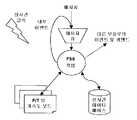
소프트웨어 모듈 아키텍처Software module architecture
초기에, 이하에 서술되는 소프트웨어 아키텍처는, 그 목적이 데이터 프로세싱 및 도구 팁(20)의 레벨 및 받침점(23)의 레벨에서의 접촉력의 추정을 위한 계산에 제한되는 소프트웨어 모듈을 일컫는다는 것에 유의해야 한다. 로봇 조작기(10), 효과기 유닛(12) 또는 시스템의 그외 다른 성분의 제어에 대한 기능 및 메커니즘은 고려하지 않는다. 이 모듈은 그렇지만 당업자에 의해 조작기 제어기의 소프트웨어 프로그램에 통합될 수 있다.Initially, it should be noted that the software architecture described below refers to a software module whose purpose is limited to the computation for estimating the contact force at the level of the data processing and
소프트웨어 모듈의 일반적인 아키텍처가 도 5에 도시되어 있다. 코어 프로세스인 FSS(힘 감지 시스템) 작업을 포함하며, 이 작업은 이하의 상태 변환 다이어그램에 의해 지배되고, 작업 배경 또는 인터럽트 서비스 루틴 레벨에서 운용되는 주요 기능에서 구현될 수 있다. 간략화를 위해, 소프트웨어 모듈은 도 5에 도시된 바와 같은 세마포어(semaphore)를 통해 실시간 클록에 의해 동기화된 주기적인 작업으로 운용되는 것으로 가정한다. FSS 작업은 실시간 운용 체제로 주어진 우선권으로 그리고 주어진 스택 사이즈로 운용된다. 소프트웨어 모듈은 새로운 메시지에 대한 각각의 클록 사이클에서 폴(poll)되는 메시지 큐(message queue)를 갖는다. 일반적으로 2가지 유형의 메시지가 있다: 기능을 실행하기 위한 커맨드 메시지 또는 상태 변환 다이어그램에서의 변환을 생성하기 위한 이벤트 메시지(아래를 참조). 커맨드 메시지는 예를 들어 조작기 제어기에 속하는 외부 모듈에 의해 생성되며, 반면 이벤트 메시지는 소프트웨어 모듈 자체에 의해 내부적으로 발생된다. 예를 들어 실패 이벤트(failure events), 커맨드 응답(command reply) 또는 정지_모션 커맨드(stip_motion command)를 발생하기 위해, 모듈은 다른 모듈 예를 들어 조작기 제어기 모듈에 보내지는 이벤트 모듈 및 커맨드 모듈을 발생할 수 있다.The general architecture of a software module is shown in FIG. Core task, which is governed by the following state transition diagram and can be implemented in the main function operating at the task background or interrupt service routine level. For simplicity, it is assumed that the software module is operated as a periodic task synchronized by a real-time clock via a semaphore as shown in FIG. FSS operations are run with the given priority as a real-time operating system and with a given stack size. The software module has a message queue that is polled in each clock cycle for a new message. There are generally two types of messages: a command message to execute a function, or an event message to generate a transformation on a state transition diagram (see below). The command message is generated, for example, by an external module that belongs to the operator controller, while the event message is generated internally by the software module itself. For example, to generate failure events, a command reply, or a stip_motion command, the module may generate an event module and a command module to be sent to another module, for example, an operator controller module .
소프트웨어 모듈에서, FSS 작업의 메인 인터페이스는 도 5에 도시된 바와 같다:In the software module, the main interface of the FSS operation is as shown in Figure 5:
- 매 클록 사이클마다 판독되는 메시지 큐;A message queue that is read every clock cycle;
- 필터링되지 않은 힘, 토크 및 가속도 데이터가 판독되는 하드웨어 보드에 대한 인터페이스;- an interface to the hardware board from which unfiltered force, torque and acceleration data is read;
- 모듈들의 기능에 의해 획득되는 정보를 판독하고 결과를 기록하기 위한 실시간 데이터베이스에 대한 인터페이스;- an interface to a real-time database for reading the information obtained by the functions of the modules and recording the results;
- 외부 모듈에 대한 커맨드 및 이벤트 메시지를 위한 인터페이스.- Interface for command and event messages to external modules.
상태 변환 다이어그램(FSS 작업)State Transition Diagram (FSS Operation)
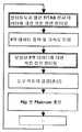
도 6은 유한 상태 머신에서 구현되는 힘 감지 시스템(FSS) 작업의 주요한 다섯 가지 상태를 나타낸다. 이하에서, 도 5에 도시된 상태에 대해 간략하게 서술한다:Figure 6 shows the five main states of the Force Sensing System (FSS) operation implemented in a finite state machine. Hereinafter, the state shown in Fig. 5 will be briefly described.
상태 1: 하드웨어 및 소프트웨어 초기화: 이 상태는 최소 침습 의료 시스템 의 소프트웨어 및 하드웨어 부분에 대한 초기화 과정에 관한 것이다. 이 초기화 과정은 조작기(10)의 제어기의 전원 투입 시(power-up) 및 부팅시(boot time)에 수행된다. 하드웨어 초기화 작업은 무엇보다도 예를 들어 F/TAS(30)의 F/T 센서 및 가속도계의 셋업 및 관련 인터페이스 보드(들)에 관한 것이다. 소프트웨어 초기화 작업은 어플리케이션의 데이터 구조를 위한 메모리와 같은 리소스, 및 그외 운용-체제 항목(예를 들어, 작업, 세마포어, 메시지 큐, 클록 등)을 할당하는 단계를 포함한다. 하드웨어 및 소프트웨어 초기화가 성공적이면, 시스템은 IDLE 상태로 진행되고, 교정 커맨드를 대기한다. 그렇지 않으면, 시스템은 도 6에 도시된 바와 같이 FAILED 상태로 진행한다. 초기화 동작의 결과는 소프트웨어 이벤트를 통해 또는 기능 호출 반환 파라미터를 통해 조작기(10)의 제어기와 통신할 수 있다.State 1: Hardware and software initialization: This state concerns the initialization process for the software and hardware portions of a minimally invasive medical system. This initialization process is performed at the time of power-up and boot time of the controller of the
상태 2: 시스템은 교정 프로세스를 시작하기 위한 커맨드를 대기하며, 이것에 대해서는 "교정 과정" 장에 서술되어 있다.State 2: The system waits for a command to start the calibration process, which is described in the chapter "Calibration procedure".
상태 3: FAULT 상태: 이 상태는 임의의 시스템/소프트웨어 조작의 경우 또는 검출된 안전 위험의 경우에 진행되고, 시스템은 재시작을 커맨드를 대기한다. FAULT 상태로 진행되면, 이 조건의 경고를 위해 비동기 메시지 또는 이벤트가 조작기 제어기에 송신된다.State 3: FAULT state: This state proceeds in case of any system / software operation or in case of a detected safety risk, and the system waits for a restart command. When proceeding to the FAULT state, an asynchronous message or event is sent to the actuator controller for warning of this condition.
상태 4: F/T & ACCELEROMETER_CALIBRATION 상태: 이 상태에서, 조작기(10)는 다른 위치 및 방향으로 미리 결정된 일련의 자세를 통해 명령이 내려진다("교정 과정" 장을 참조). 각각의 자세에서, F/T 센서 및 가속도계 데이터는 '기록' 커맨드의 수신하에 기록된다. 일련의 자세의 완료 후, '계산' 커맨드를 수신하면, 전술 한 최소 자승 맞춤 기법, 또는 임의의 다른 적절한 근사 기법을 적용하여 부착된 부하의 중력의 중심의 좌표와 함께 F/T 센서 및 가속도계 오프셋(


상태 5: APPLICATION_LOADS_EVALUATION 상태: 이 상태에서는 주기적인 프로세스가 이하의 동작을 순차적으로 실행하지만, 반드시 주어진 순서로 실행할 필요는 없다:State 5: APPLICATION_LOADS_EVALUATION state: In this state, the periodic process executes the following operations sequentially, but not necessarily in the order given:
- 선형 확률 프로세스를 위한, 예를 들어 이산 칼만 필터 직렬에 의한 데이터 필터링("센서 데이터 필터링" 장을 참조);- data filtering for linear probability processes, for example discrete Kalman filter serials (see chapter "Sensor data filtering");
- F/T 센서 데이터의 중력 효과 및 동적 하중에 대한 보상("중력의 오프셋 및 동적 하중의 오프셋의 보상" 장을 참조)- compensation of gravity effects and dynamic loads of F / T sensor data (see chapter "compensation of gravity offsets and dynamic load offsets")
- 받침점(23)과 관련해서 도구(14)의 위치의 결정, 즉 조작기(10) 모션에 기초한 연속적인 갱신("받침점과 관련해서 도구 위치를 결정하기" 장을 참조);- determination of the position of the
- 도구 팁(20)에서 그리고 받침점에서 각각 힘의 추정을 계산("도구 팁에서 그리고 받침점 레벨에서 힘을 계산하기" 장을 참조);- Compute an estimate of the force at the tool tip (20) and at the fulcrum (see chapter "Calculating force at the tool tip and fulcrum level");
선택적으로 이하의 추가의 동작도 또한 주기적인 프로세스에 의해 수행된다:Optionally, the following additional operations are also performed by the periodic process:
- 예를 들어 실시간 데이터베이스에 저장되어 있는 미리 결정된 최대 임계값들에 대한 보상된 부하에 대한 모니터링. 임계값들을 초과하는 경우, 기능은 경고 메시지 또는 중지 모션 커맨드를 발생하고, 이 조건을 실시간 데이터베이스에 기록한다: 이 프로세스는 또한 F/TAS(30)의 불안전한 조건 또는 실패를 검출하기 위해 도구 팁(20)에서 그리고 받침점 레벨(투관침(22))에서 그 추정된 힘에 인가될 수 있다.- Monitoring for compensated loads for predetermined maximum thresholds, for example, stored in a real-time database. If the thresholds are exceeded, the function generates a warning message or a stop motion command and writes this condition to the real time database: This process also includes a tool tip (not shown) to detect an unsafe condition or failure of the F / (20) and at the fulcrum level (trocar 22).
- 센서 오프셋의 드리프트를 검사("오프셋 드리프트의 검사" 장을 참조)- check the drift of the sensor offset (see chapter "Inspection of offset drift")
- 복부내 흡입 압력의 모니터링. 압력 저하의 경우, 기능은 경로 메시지를 발생하여 적절한 행동이 취해지는데, 예를 들어 받침점(23)의 위치가 다시 정해진다.- Monitoring abdominal suction pressure. In the case of a pressure drop, the function generates a path message to take appropriate action, for example the position of the
도 7은 흐름도에서 위의 동작들의 가능한 시퀀스를 나타낸다. 도 7에 보여지는 바와 같이, 예를 들어 도 4와 관련해서 서술된 바와 같이, 직렬 구조의 1차 선형 칼만 필터는 "기생 부하"의 보상 이전에 센서 데이터를 필터링한다. 보상 후, 2차 선형 칼만 필터가 힘 및 토크 값에 대해 적용되어, 힘 추정치(들)를 계산(

도 8은 흐름도에서 상기 동작들에 대한 대안의 시퀀스를 나타낸다. 도 8에 도시된 바와 같이, 힘 추정치(들)를 계산(

도 8의 대안은 힘 추정치(들)의 계산 이전에, 필터링으로 인한 (과소의/과대의 부하) 정보의 손실을 감소하여, 정확성이 추가로 높아질 수 있다. 도 7의 실시예는 시스템이 예를 들어 도구(14)의 삽입 동안 조작기(10)의 보조 위치선정을 위해 제어 디바이스("조이스틱")와 같이 효과기 유닛(12)을 사용하여 구성되는 경우에 바람직하다.The alternative of FIG. 8 may reduce the loss of information due to filtering (under / overload) information prior to the calculation of the force estimate (s), so that the accuracy may be further increased. The embodiment of Figure 7 is preferred when the system is configured using an
재교정의 요구가 접수되는 경우, 시스템의 상태는 F/T_&_ACCELEROMETER_CALIBRATION으로 변화며 그 주기적인 프로세스는 중지된다. 소프트웨어 또는 하드웨어 실패 검출의 경우, 시스템은 FAULT 상태로 변화며 경고가 발생된다.When a request for recalibration is received, the state of the system changes to F / T_ & _ ACCELEROMETER_CALIBRATION, and the periodic process stops. In the case of software or hardware failure detection, the system changes to the FAULT state and an alert is generated.
주기적인 프로세스의 실행 속도는 어플리케이션 요건에 따라 구성된다. 예를 들어, 로봇 원격 조정을 위해 보상된 데이터를 사용할 때, 이 프로세스는 바람직하게 조작기(10)를 위한 셋-포인트 발생의 속도와 동일한 속도, 예를 들어 300Hz 내지 1000Hz로 운용될 것이다.The execution speed of the periodic process is configured according to application requirements. For example, when using compensated data for robot remote control, this process will preferably be run at the same rate as the set-point occurrence for
결론conclusion
제안된 방법/시스템은 도구 팁에서 그리고 선택적으로 투관침 레벨에서 접촉력을 추정하는 정확하고 저렴한 방식을 제공함으로써 로봇 및/또는 컴퓨터를 이용한 최소 침습 수술에 기여한다.The proposed method / system contributes to minimally invasive surgery using a robot and / or computer by providing an accurate and inexpensive way to estimate the contact force at the tool tip and optionally at the trocar level.
원형의 시스템(prototype system)의 실험실 연구에서는, 0.25N의 평균 추정 에러 및 0.65N의 최대 추정 에러가 결정되어 왔다. 개발 중인 원형을 이용하여 이러한 값들이 달성되어도, 0.25N은 사람의 손의 감도 임계값 아래이기 때문에 추정 에러 레벨은 대부분의 외과 복강경 검사 작업에서 만족스럽다는 것에 유의해야 한다. 또한, 원형으로 달성된 50ms의 전체 신호 지연에 따라, 시스템이 원격 조정에 쉽게 적합하게 된다는 것을 이해할 수 있을 것이다.In a laboratory study of a prototype system, an average estimation error of 0.25 N and a maximum estimation error of 0.65 N have been determined. It should be noted that even though these values are achieved using the prototype under development, the estimated error level is satisfactory in most surgical laparoscopic examinations because 0.25N is below the sensitivity threshold of the human hand. It will also be appreciated that with a 50ms total signal delay achieved in a circular fashion, the system is easily adapted to remote control.
Claims (26)
Translated fromKoreanApplications Claiming Priority (3)
| Application Number | Priority Date | Filing Date | Title |
|---|---|---|---|
| EP06122937.3 | 2006-10-25 | ||
| EP06122937AEP1915963A1 (en) | 2006-10-25 | 2006-10-25 | Force estimation for a minimally invasive robotic surgery system |
| PCT/EP2007/061494WO2008049898A1 (en) | 2006-10-25 | 2007-10-25 | Force estimation for a minimally invasive robotic surgery system |
Related Child Applications (1)
| Application Number | Title | Priority Date | Filing Date |
|---|---|---|---|
| KR1020127017281ADivisionKR101572902B1 (en) | 2006-10-25 | 2007-10-25 | Force estimation for a minimally invasive robotic surgery system |
Publications (2)
| Publication Number | Publication Date |
|---|---|
| KR20090094234A KR20090094234A (en) | 2009-09-04 |
| KR101404447B1true KR101404447B1 (en) | 2014-06-20 |
Family
ID=37745859
Family Applications (2)
| Application Number | Title | Priority Date | Filing Date |
|---|---|---|---|
| KR1020097008933AActiveKR101404447B1 (en) | 2006-10-25 | 2007-10-25 | Force estimation for a minimally invasive robotic surgery system |
| KR1020127017281AActiveKR101572902B1 (en) | 2006-10-25 | 2007-10-25 | Force estimation for a minimally invasive robotic surgery system |
Family Applications After (1)
| Application Number | Title | Priority Date | Filing Date |
|---|---|---|---|
| KR1020127017281AActiveKR101572902B1 (en) | 2006-10-25 | 2007-10-25 | Force estimation for a minimally invasive robotic surgery system |
Country Status (15)
| Country | Link |
|---|---|
| US (5) | US9855662B2 (en) |
| EP (3) | EP1915963A1 (en) |
| JP (2) | JP5044659B2 (en) |
| KR (2) | KR101404447B1 (en) |
| CN (2) | CN101528151B (en) |
| BR (2) | BRPI0717408B8 (en) |
| CA (2) | CA2664997C (en) |
| CY (2) | CY1116282T1 (en) |
| DK (2) | DK2083737T3 (en) |
| ES (2) | ES2535843T3 (en) |
| MX (2) | MX338904B (en) |
| PL (2) | PL2491884T3 (en) |
| PT (2) | PT2083737E (en) |
| RU (2) | RU2462342C2 (en) |
| WO (1) | WO2008049898A1 (en) |
Cited By (1)
| Publication number | Priority date | Publication date | Assignee | Title |
|---|---|---|---|---|
| KR20210002278A (en)* | 2019-06-28 | 2021-01-07 | 성균관대학교산학협력단 | Force/torque sensor capable of auto calibration and auto calibration method |
Families Citing this family (646)
| Publication number | Priority date | Publication date | Assignee | Title |
|---|---|---|---|---|
| US20070084897A1 (en) | 2003-05-20 | 2007-04-19 | Shelton Frederick E Iv | Articulating surgical stapling instrument incorporating a two-piece e-beam firing mechanism |
| US9060770B2 (en) | 2003-05-20 | 2015-06-23 | Ethicon Endo-Surgery, Inc. | Robotically-driven surgical instrument with E-beam driver |
| US9072535B2 (en) | 2011-05-27 | 2015-07-07 | Ethicon Endo-Surgery, Inc. | Surgical stapling instruments with rotatable staple deployment arrangements |
| US8215531B2 (en) | 2004-07-28 | 2012-07-10 | Ethicon Endo-Surgery, Inc. | Surgical stapling instrument having a medical substance dispenser |
| US11890012B2 (en) | 2004-07-28 | 2024-02-06 | Cilag Gmbh International | Staple cartridge comprising cartridge body and attached support |
| US11998198B2 (en) | 2004-07-28 | 2024-06-04 | Cilag Gmbh International | Surgical stapling instrument incorporating a two-piece E-beam firing mechanism |
| US8465474B2 (en) | 2009-05-19 | 2013-06-18 | Intuitive Surgical Operations, Inc. | Cleaning of a surgical instrument force sensor |
| US9237891B2 (en) | 2005-08-31 | 2016-01-19 | Ethicon Endo-Surgery, Inc. | Robotically-controlled surgical stapling devices that produce formed staples having different lengths |
| US7934630B2 (en) | 2005-08-31 | 2011-05-03 | Ethicon Endo-Surgery, Inc. | Staple cartridges for forming staples having differing formed staple heights |
| US11246590B2 (en) | 2005-08-31 | 2022-02-15 | Cilag Gmbh International | Staple cartridge including staple drivers having different unfired heights |
| US7669746B2 (en) | 2005-08-31 | 2010-03-02 | Ethicon Endo-Surgery, Inc. | Staple cartridges for forming staples having differing formed staple heights |
| US11484312B2 (en) | 2005-08-31 | 2022-11-01 | Cilag Gmbh International | Staple cartridge comprising a staple driver arrangement |
| US10159482B2 (en) | 2005-08-31 | 2018-12-25 | Ethicon Llc | Fastener cartridge assembly comprising a fixed anvil and different staple heights |
| US20070106317A1 (en) | 2005-11-09 | 2007-05-10 | Shelton Frederick E Iv | Hydraulically and electrically actuated articulation joints for surgical instruments |
| US8628518B2 (en) | 2005-12-30 | 2014-01-14 | Intuitive Surgical Operations, Inc. | Wireless force sensor on a distal portion of a surgical instrument and method |
| US20120292367A1 (en) | 2006-01-31 | 2012-11-22 | Ethicon Endo-Surgery, Inc. | Robotically-controlled end effector |
| US8820603B2 (en) | 2006-01-31 | 2014-09-02 | Ethicon Endo-Surgery, Inc. | Accessing data stored in a memory of a surgical instrument |
| US8708213B2 (en) | 2006-01-31 | 2014-04-29 | Ethicon Endo-Surgery, Inc. | Surgical instrument having a feedback system |
| US7753904B2 (en) | 2006-01-31 | 2010-07-13 | Ethicon Endo-Surgery, Inc. | Endoscopic surgical instrument with a handle that can articulate with respect to the shaft |
| US20110024477A1 (en) | 2009-02-06 | 2011-02-03 | Hall Steven G | Driven Surgical Stapler Improvements |
| US11278279B2 (en) | 2006-01-31 | 2022-03-22 | Cilag Gmbh International | Surgical instrument assembly |
| US7845537B2 (en) | 2006-01-31 | 2010-12-07 | Ethicon Endo-Surgery, Inc. | Surgical instrument having recording capabilities |
| US20110295295A1 (en) | 2006-01-31 | 2011-12-01 | Ethicon Endo-Surgery, Inc. | Robotically-controlled surgical instrument having recording capabilities |
| US11793518B2 (en) | 2006-01-31 | 2023-10-24 | Cilag Gmbh International | Powered surgical instruments with firing system lockout arrangements |
| US8186555B2 (en) | 2006-01-31 | 2012-05-29 | Ethicon Endo-Surgery, Inc. | Motor-driven surgical cutting and fastening instrument with mechanical closure system |
| US11224427B2 (en) | 2006-01-31 | 2022-01-18 | Cilag Gmbh International | Surgical stapling system including a console and retraction assembly |
| US8992422B2 (en) | 2006-03-23 | 2015-03-31 | Ethicon Endo-Surgery, Inc. | Robotically-controlled endoscopic accessory channel |
| US8322455B2 (en) | 2006-06-27 | 2012-12-04 | Ethicon Endo-Surgery, Inc. | Manually driven surgical cutting and fastening instrument |
| US7506791B2 (en) | 2006-09-29 | 2009-03-24 | Ethicon Endo-Surgery, Inc. | Surgical stapling instrument with mechanical mechanism for limiting maximum tissue compression |
| US10568652B2 (en) | 2006-09-29 | 2020-02-25 | Ethicon Llc | Surgical staples having attached drivers of different heights and stapling instruments for deploying the same |
| US11980366B2 (en) | 2006-10-03 | 2024-05-14 | Cilag Gmbh International | Surgical instrument |
| EP1915963A1 (en) | 2006-10-25 | 2008-04-30 | The European Atomic Energy Community (EURATOM), represented by the European Commission | Force estimation for a minimally invasive robotic surgery system |
| US12290277B2 (en) | 2007-01-02 | 2025-05-06 | Aquabeam, Llc | Tissue resection with pressure sensing |
| US8632535B2 (en) | 2007-01-10 | 2014-01-21 | Ethicon Endo-Surgery, Inc. | Interlock and surgical instrument including same |
| US8652120B2 (en) | 2007-01-10 | 2014-02-18 | Ethicon Endo-Surgery, Inc. | Surgical instrument with wireless communication between control unit and sensor transponders |
| US8684253B2 (en) | 2007-01-10 | 2014-04-01 | Ethicon Endo-Surgery, Inc. | Surgical instrument with wireless communication between a control unit of a robotic system and remote sensor |
| US11291441B2 (en) | 2007-01-10 | 2022-04-05 | Cilag Gmbh International | Surgical instrument with wireless communication between control unit and remote sensor |
| US11039836B2 (en) | 2007-01-11 | 2021-06-22 | Cilag Gmbh International | Staple cartridge for use with a surgical stapling instrument |
| US20080169333A1 (en) | 2007-01-11 | 2008-07-17 | Shelton Frederick E | Surgical stapler end effector with tapered distal end |
| US7673782B2 (en) | 2007-03-15 | 2010-03-09 | Ethicon Endo-Surgery, Inc. | Surgical stapling instrument having a releasable buttress material |
| US8893946B2 (en) | 2007-03-28 | 2014-11-25 | Ethicon Endo-Surgery, Inc. | Laparoscopic tissue thickness and clamp load measuring devices |
| US11564682B2 (en) | 2007-06-04 | 2023-01-31 | Cilag Gmbh International | Surgical stapler device |
| US8931682B2 (en) | 2007-06-04 | 2015-01-13 | Ethicon Endo-Surgery, Inc. | Robotically-controlled shaft based rotary drive systems for surgical instruments |
| US7753245B2 (en) | 2007-06-22 | 2010-07-13 | Ethicon Endo-Surgery, Inc. | Surgical stapling instruments |
| US11849941B2 (en) | 2007-06-29 | 2023-12-26 | Cilag Gmbh International | Staple cartridge having staple cavities extending at a transverse angle relative to a longitudinal cartridge axis |
| US8636736B2 (en) | 2008-02-14 | 2014-01-28 | Ethicon Endo-Surgery, Inc. | Motorized surgical cutting and fastening instrument |
| US11986183B2 (en) | 2008-02-14 | 2024-05-21 | Cilag Gmbh International | Surgical cutting and fastening instrument comprising a plurality of sensors to measure an electrical parameter |
| US8573465B2 (en) | 2008-02-14 | 2013-11-05 | Ethicon Endo-Surgery, Inc. | Robotically-controlled surgical end effector system with rotary actuated closure systems |
| JP5410110B2 (en) | 2008-02-14 | 2014-02-05 | エシコン・エンド−サージェリィ・インコーポレイテッド | Surgical cutting / fixing instrument with RF electrode |
| US7819298B2 (en) | 2008-02-14 | 2010-10-26 | Ethicon Endo-Surgery, Inc. | Surgical stapling apparatus with control features operable with one hand |
| US9179912B2 (en) | 2008-02-14 | 2015-11-10 | Ethicon Endo-Surgery, Inc. | Robotically-controlled motorized surgical cutting and fastening instrument |
| US8758391B2 (en) | 2008-02-14 | 2014-06-24 | Ethicon Endo-Surgery, Inc. | Interchangeable tools for surgical instruments |
| US7866527B2 (en) | 2008-02-14 | 2011-01-11 | Ethicon Endo-Surgery, Inc. | Surgical stapling apparatus with interlockable firing system |
| US11272927B2 (en) | 2008-02-15 | 2022-03-15 | Cilag Gmbh International | Layer arrangements for surgical staple cartridges |
| US9585657B2 (en) | 2008-02-15 | 2017-03-07 | Ethicon Endo-Surgery, Llc | Actuator for releasing a layer of material from a surgical end effector |
| ES2769535T3 (en) | 2008-03-06 | 2020-06-26 | Aquabeam Llc | Tissue ablation and cauterization with optical energy carried in a fluid stream |
| DE102008016146B4 (en)* | 2008-03-28 | 2010-01-28 | Aktormed Gmbh | Operation assistance system for guiding a surgical auxiliary instrument |
| ES2338623B1 (en)* | 2008-08-05 | 2012-02-07 | Universidad Miguel Hernandez | ROBOTIC ARM. |
| US10532466B2 (en)* | 2008-08-22 | 2020-01-14 | Titan Medical Inc. | Robotic hand controller |
| US8332072B1 (en) | 2008-08-22 | 2012-12-11 | Titan Medical Inc. | Robotic hand controller |
| US9005230B2 (en) | 2008-09-23 | 2015-04-14 | Ethicon Endo-Surgery, Inc. | Motorized surgical instrument |
| US8210411B2 (en) | 2008-09-23 | 2012-07-03 | Ethicon Endo-Surgery, Inc. | Motor-driven surgical cutting instrument |
| US9386983B2 (en) | 2008-09-23 | 2016-07-12 | Ethicon Endo-Surgery, Llc | Robotically-controlled motorized surgical instrument |
| US11648005B2 (en) | 2008-09-23 | 2023-05-16 | Cilag Gmbh International | Robotically-controlled motorized surgical instrument with an end effector |
| US8608045B2 (en) | 2008-10-10 | 2013-12-17 | Ethicon Endo-Sugery, Inc. | Powered surgical cutting and stapling apparatus with manually retractable firing system |
| US8594841B2 (en) | 2008-12-31 | 2013-11-26 | Intuitive Surgical Operations, Inc. | Visual force feedback in a minimally invasive surgical procedure |
| US8374723B2 (en)* | 2008-12-31 | 2013-02-12 | Intuitive Surgical Operations, Inc. | Obtaining force information in a minimally invasive surgical procedure |
| US8517239B2 (en) | 2009-02-05 | 2013-08-27 | Ethicon Endo-Surgery, Inc. | Surgical stapling instrument comprising a magnetic element driver |
| RU2525225C2 (en) | 2009-02-06 | 2014-08-10 | Этикон Эндо-Серджери, Инк. | Improvement of drive surgical suturing instrument |
| US8444036B2 (en) | 2009-02-06 | 2013-05-21 | Ethicon Endo-Surgery, Inc. | Motor driven surgical fastener device with mechanisms for adjusting a tissue gap within the end effector |
| DE102009002435A1 (en)* | 2009-04-16 | 2010-10-21 | Airbus Deutschland Gmbh | A high lift system for an aircraft and method for detecting faults in a high lift system for an aircraft |
| US8851354B2 (en) | 2009-12-24 | 2014-10-07 | Ethicon Endo-Surgery, Inc. | Surgical cutting instrument that analyzes tissue thickness |
| US8220688B2 (en) | 2009-12-24 | 2012-07-17 | Ethicon Endo-Surgery, Inc. | Motor-driven surgical cutting instrument with electric actuator directional control assembly |
| CN101785704B (en)* | 2010-01-15 | 2012-06-06 | 广东工业大学 | Self-adaptive filtering device of master-slave minimally-invasive surgery robot system |
| IT1401669B1 (en) | 2010-04-07 | 2013-08-02 | Sofar Spa | ROBOTIC SURGERY SYSTEM WITH PERFECT CONTROL. |
| BE1019279A3 (en)* | 2010-04-08 | 2012-05-08 | Rutten Leon | SCRATCHING METHOD AND CONTROL DEVICE FOR SUCH A METHOD. |
| US8783543B2 (en) | 2010-07-30 | 2014-07-22 | Ethicon Endo-Surgery, Inc. | Tissue acquisition arrangements and methods for surgical stapling devices |
| JP5645564B2 (en)* | 2010-09-14 | 2014-12-24 | キヤノン株式会社 | Sensor device and robot device |
| DE102010040987A1 (en)* | 2010-09-17 | 2012-03-22 | Siemens Aktiengesellschaft | Method for placing a laparoscopic robot in a predeterminable relative position to a trocar |
| US9386988B2 (en) | 2010-09-30 | 2016-07-12 | Ethicon End-Surgery, LLC | Retainer assembly including a tissue thickness compensator |
| US11925354B2 (en) | 2010-09-30 | 2024-03-12 | Cilag Gmbh International | Staple cartridge comprising staples positioned within a compressible portion thereof |
| US9788834B2 (en) | 2010-09-30 | 2017-10-17 | Ethicon Llc | Layer comprising deployable attachment members |
| US11812965B2 (en) | 2010-09-30 | 2023-11-14 | Cilag Gmbh International | Layer of material for a surgical end effector |
| US11298125B2 (en) | 2010-09-30 | 2022-04-12 | Cilag Gmbh International | Tissue stapler having a thickness compensator |
| US9629814B2 (en) | 2010-09-30 | 2017-04-25 | Ethicon Endo-Surgery, Llc | Tissue thickness compensator configured to redistribute compressive forces |
| US9232941B2 (en) | 2010-09-30 | 2016-01-12 | Ethicon Endo-Surgery, Inc. | Tissue thickness compensator comprising a reservoir |
| US9364233B2 (en) | 2010-09-30 | 2016-06-14 | Ethicon Endo-Surgery, Llc | Tissue thickness compensators for circular surgical staplers |
| US12213666B2 (en) | 2010-09-30 | 2025-02-04 | Cilag Gmbh International | Tissue thickness compensator comprising layers |
| US10945731B2 (en) | 2010-09-30 | 2021-03-16 | Ethicon Llc | Tissue thickness compensator comprising controlled release and expansion |
| US9016542B2 (en) | 2010-09-30 | 2015-04-28 | Ethicon Endo-Surgery, Inc. | Staple cartridge comprising compressible distortion resistant components |
| US9351730B2 (en) | 2011-04-29 | 2016-05-31 | Ethicon Endo-Surgery, Llc | Tissue thickness compensator comprising channels |
| EP2622594B1 (en) | 2010-10-01 | 2018-08-22 | Applied Medical Resources Corporation | Portable laparoscopic trainer |
| US8695866B2 (en) | 2010-10-01 | 2014-04-15 | Ethicon Endo-Surgery, Inc. | Surgical instrument having a power control circuit |
| JP5215378B2 (en)* | 2010-12-27 | 2013-06-19 | ファナック株式会社 | Robot control device that controls force using a triaxial force sensor |
| US9119655B2 (en) | 2012-08-03 | 2015-09-01 | Stryker Corporation | Surgical manipulator capable of controlling a surgical instrument in multiple modes |
| US9921712B2 (en) | 2010-12-29 | 2018-03-20 | Mako Surgical Corp. | System and method for providing substantially stable control of a surgical tool |
| JP5682314B2 (en)* | 2011-01-06 | 2015-03-11 | セイコーエプソン株式会社 | robot |
| US9068438B2 (en)* | 2011-01-28 | 2015-06-30 | Baker Hughes Incorporated | Optimization of sample cleanup during formation testing |
| US20160143749A1 (en)* | 2011-04-08 | 2016-05-26 | The General Hospital Corporation | Glenoid component installation procedure and tooling for shoulder arthroplasty |
| AU2012250197B2 (en) | 2011-04-29 | 2017-08-10 | Ethicon Endo-Surgery, Inc. | Staple cartridge comprising staples positioned within a compressible portion thereof |
| CN102151179B (en)* | 2011-05-13 | 2012-07-04 | 南开大学 | Three-dimensional force sensor for minimally invasive surgery robot |
| US11207064B2 (en) | 2011-05-27 | 2021-12-28 | Cilag Gmbh International | Automated end effector component reloading system for use with a robotic system |
| CN102359839B (en)* | 2011-08-19 | 2012-11-28 | 青岛大学 | Medical pressure detection apparatus |
| US9140598B2 (en)* | 2011-09-20 | 2015-09-22 | Ishida Co., Ltd. | Mass measurement device |
| US9060794B2 (en) | 2011-10-18 | 2015-06-23 | Mako Surgical Corp. | System and method for robotic surgery |
| US9218753B2 (en) | 2011-10-21 | 2015-12-22 | Applied Medical Resources Corporation | Simulated tissue structure for surgical training |
| SG11201402020XA (en)* | 2011-11-04 | 2014-09-26 | Univ Johns Hopkins | Steady hand micromanipulation robot |
| KR101828453B1 (en)* | 2011-12-09 | 2018-02-13 | 삼성전자주식회사 | Medical robotic system and control method for thereof |
| KR101953187B1 (en) | 2011-12-20 | 2019-02-28 | 어플라이드 메디컬 리소시스 코포레이션 | Advanced surgical simulation |
| RU2491161C1 (en)* | 2012-01-10 | 2013-08-27 | Олег Владимирович Галимов | Robotic system for minimally invasive surgery |
| JP5966372B2 (en)* | 2012-01-17 | 2016-08-10 | セイコーエプソン株式会社 | Robot control apparatus, robot system, robot control method, and robot |
| US9044230B2 (en) | 2012-02-13 | 2015-06-02 | Ethicon Endo-Surgery, Inc. | Surgical cutting and fastening instrument with apparatus for determining cartridge and firing motion status |
| EP3351196A1 (en) | 2012-02-29 | 2018-07-25 | Procept Biorobotics Corporation | Automated image-guided tissue resection and treatment |
| MX358135B (en) | 2012-03-28 | 2018-08-06 | Ethicon Endo Surgery Inc | Tissue thickness compensator comprising a plurality of layers. |
| BR112014024098B1 (en) | 2012-03-28 | 2021-05-25 | Ethicon Endo-Surgery, Inc. | staple cartridge |
| JP6224070B2 (en) | 2012-03-28 | 2017-11-01 | エシコン・エンド−サージェリィ・インコーポレイテッドEthicon Endo−Surgery,Inc. | Retainer assembly including tissue thickness compensator |
| KR101358668B1 (en)* | 2012-05-21 | 2014-02-11 | 한국과학기술원 | Apparatus for measuring force or torque of multi-DOFs gripper device on a slider of robot arms and method of the same |
| KR101358669B1 (en)* | 2012-05-21 | 2014-02-24 | 한국과학기술원 | Apparatus for measuring force or torque of multi-DOFs gripper device on a slider of robot arms and method of the same |
| US9101358B2 (en) | 2012-06-15 | 2015-08-11 | Ethicon Endo-Surgery, Inc. | Articulatable surgical instrument comprising a firing drive |
| JP6053342B2 (en)* | 2012-06-15 | 2016-12-27 | キヤノン株式会社 | Medical manipulator and medical imaging system including the medical manipulator |
| US9282974B2 (en) | 2012-06-28 | 2016-03-15 | Ethicon Endo-Surgery, Llc | Empty clip cartridge lockout |
| US20140005718A1 (en) | 2012-06-28 | 2014-01-02 | Ethicon Endo-Surgery, Inc. | Multi-functional powered surgical device with external dissection features |
| US20140001231A1 (en) | 2012-06-28 | 2014-01-02 | Ethicon Endo-Surgery, Inc. | Firing system lockout arrangements for surgical instruments |
| US12383267B2 (en) | 2012-06-28 | 2025-08-12 | Cilag Gmbh International | Robotically powered surgical device with manually-actuatable reversing system |
| BR112014032776B1 (en) | 2012-06-28 | 2021-09-08 | Ethicon Endo-Surgery, Inc | SURGICAL INSTRUMENT SYSTEM AND SURGICAL KIT FOR USE WITH A SURGICAL INSTRUMENT SYSTEM |
| US9289256B2 (en) | 2012-06-28 | 2016-03-22 | Ethicon Endo-Surgery, Llc | Surgical end effectors having angled tissue-contacting surfaces |
| JP6290201B2 (en) | 2012-06-28 | 2018-03-07 | エシコン・エンド−サージェリィ・インコーポレイテッドEthicon Endo−Surgery,Inc. | Lockout for empty clip cartridge |
| US11278284B2 (en) | 2012-06-28 | 2022-03-22 | Cilag Gmbh International | Rotary drive arrangements for surgical instruments |
| US9408606B2 (en) | 2012-06-28 | 2016-08-09 | Ethicon Endo-Surgery, Llc | Robotically powered surgical device with manually-actuatable reversing system |
| KR20140008728A (en)* | 2012-07-11 | 2014-01-22 | 삼성전자주식회사 | Palpation apparatus and method using robot |
| JP5727103B2 (en)* | 2012-08-02 | 2015-06-03 | 東芝機械株式会社 | Robot apparatus and control method thereof |
| CA2880277A1 (en) | 2012-08-03 | 2014-02-06 | Applied Medical Resources Corporation | Simulated stapling and energy based ligation for surgical training |
| CN107198567B (en) | 2012-08-03 | 2021-02-09 | 史赛克公司 | Systems and methods for robotic surgery |
| US9226796B2 (en) | 2012-08-03 | 2016-01-05 | Stryker Corporation | Method for detecting a disturbance as an energy applicator of a surgical instrument traverses a cutting path |
| KR102184960B1 (en) | 2012-08-15 | 2020-12-01 | 인튜어티브 서지컬 오퍼레이션즈 인코포레이티드 | Movable surgical mounting platform controlled by manual motion of robotic arms |
| JP6111562B2 (en)* | 2012-08-31 | 2017-04-12 | セイコーエプソン株式会社 | robot |
| JP2015532450A (en) | 2012-09-26 | 2015-11-09 | アプライド メディカル リソーシーズ コーポレイション | Surgical training model for laparoscopic procedures |
| WO2014052612A1 (en) | 2012-09-27 | 2014-04-03 | Applied Medical Resources Corporation | Surgical training model for laparoscopic procedures |
| US10679520B2 (en) | 2012-09-27 | 2020-06-09 | Applied Medical Resources Corporation | Surgical training model for laparoscopic procedures |
| US9959786B2 (en) | 2012-09-27 | 2018-05-01 | Applied Medical Resources Corporation | Surgical training model for laparoscopic procedures |
| EP2901439A1 (en) | 2012-09-28 | 2015-08-05 | Applied Medical Resources Corporation | Surgical training model for laparoscopic procedures |
| CA2885314C (en) | 2012-09-28 | 2021-01-19 | Applied Medical Resources Corporation | Surgical training model for transluminal laparoscopic procedures |
| JP2014134530A (en) | 2012-12-14 | 2014-07-24 | Panasonic Corp | Force measurement device, force measurement method, force measurement program, force measurement integrated electronic circuit and master-slave device |
| RU2672520C2 (en) | 2013-03-01 | 2018-11-15 | Этикон Эндо-Серджери, Инк. | Hingedly turnable surgical instruments with conducting ways for signal transfer |
| BR112015021082B1 (en) | 2013-03-01 | 2022-05-10 | Ethicon Endo-Surgery, Inc | surgical instrument |
| AU2014224004B2 (en) | 2013-03-01 | 2018-04-05 | Applied Medical Resources Corporation | Advanced surgical simulation constructions and methods |
| KR102203516B1 (en) | 2013-03-12 | 2021-01-18 | 스트리커 코포레이션 | Sensor assembly and method for measuring forces and torques |
| US9808244B2 (en) | 2013-03-14 | 2017-11-07 | Ethicon Llc | Sensor arrangements for absolute positioning system for surgical instruments |
| US9629629B2 (en) | 2013-03-14 | 2017-04-25 | Ethicon Endo-Surgey, LLC | Control systems for surgical instruments |
| US9826976B2 (en) | 2013-04-16 | 2017-11-28 | Ethicon Llc | Motor driven surgical instruments with lockable dual drive shafts |
| BR112015026109B1 (en) | 2013-04-16 | 2022-02-22 | Ethicon Endo-Surgery, Inc | surgical instrument |
| GB201306923D0 (en)* | 2013-04-17 | 2013-05-29 | Gencoa Ltd | Auto-tuning |
| US20140323904A1 (en)* | 2013-04-30 | 2014-10-30 | Elwha Llc | Stabilized device for remote palpation of tissue |
| CA3139494A1 (en) | 2013-05-15 | 2014-11-20 | Applied Medical Resources Corporation | Hernia model |
| JP5962590B2 (en)* | 2013-05-31 | 2016-08-03 | 株式会社安川電機 | Robot system and method of manufacturing workpiece |
| KR102607634B1 (en) | 2013-06-18 | 2023-11-29 | 어플라이드 메디컬 리소시스 코포레이션 | Gallbladder model for teaching and practicing surgical procedures |
| KR102206198B1 (en)* | 2013-07-10 | 2021-01-22 | 삼성전자주식회사 | Surgical robot system and method of controlling the same |
| US10198966B2 (en) | 2013-07-24 | 2019-02-05 | Applied Medical Resources Corporation | Advanced first entry model for surgical simulation |
| AU2014293036B2 (en) | 2013-07-24 | 2017-12-21 | Applied Medical Resources Corporation | First entry model |
| EP3597135B1 (en) | 2013-08-15 | 2021-12-15 | Intuitive Surgical Operations, Inc. | Variable instrument preload mechanism controller |
| KR102313228B1 (en) | 2013-08-15 | 2021-10-18 | 인튜어티브 서지컬 오퍼레이션즈 인코포레이티드 | Actuator interface to instrument sterile adapter |
| CN108784838B (en) | 2013-08-15 | 2021-06-08 | 直观外科手术操作公司 | Instrument sterile adapter drive interface |
| CN109602495B (en) | 2013-08-15 | 2021-05-11 | 直观外科手术操作公司 | Instrument sterile adapter drive features |
| EP3708105B1 (en) | 2013-08-15 | 2022-02-09 | Intuitive Surgical Operations, Inc. | Preloaded surgical instrument interface |
| US10016244B2 (en) | 2013-08-15 | 2018-07-10 | Intuitive Surgical Operations, Inc. | Robotic instrument driven element |
| MX369362B (en) | 2013-08-23 | 2019-11-06 | Ethicon Endo Surgery Llc | Firing member retraction devices for powered surgical instruments. |
| US9775609B2 (en) | 2013-08-23 | 2017-10-03 | Ethicon Llc | Tamper proof circuit for surgical instrument battery pack |
| KR102306959B1 (en) | 2013-09-04 | 2021-10-01 | 삼성전자주식회사 | Surgical robot and control method thereof |
| EP3037222B1 (en)* | 2013-09-24 | 2025-08-27 | Sony Olympus Medical Solutions Inc. | Medical robot arm system and program |
| US9817019B2 (en) | 2013-11-13 | 2017-11-14 | Intuitive Surgical Operations, Inc. | Integrated fiber bragg grating accelerometer in a surgical instrument |
| US10709510B2 (en) | 2013-12-17 | 2020-07-14 | Corindus, Inc. | System and method for controlling a motor in a catheter procedure system |
| US9962161B2 (en) | 2014-02-12 | 2018-05-08 | Ethicon Llc | Deliverable surgical instrument |
| JP6462004B2 (en) | 2014-02-24 | 2019-01-30 | エシコン エルエルシー | Fastening system with launcher lockout |
| JP6278747B2 (en)* | 2014-02-28 | 2018-02-14 | オリンパス株式会社 | Manipulator calibration method, manipulator, and manipulator system |
| KR102300251B1 (en)* | 2014-03-17 | 2021-09-09 | 인튜어티브 서지컬 오퍼레이션즈 인코포레이티드 | Automatic push-out to avoid range of motion limits |
| WO2015143281A1 (en)* | 2014-03-21 | 2015-09-24 | President And Fellows Of Harvard College | Monolithic, multi-axis force sensor |
| ES2891756T3 (en) | 2014-03-26 | 2022-01-31 | Applied Med Resources | Simulated dissectable tissue |
| US20150272580A1 (en) | 2014-03-26 | 2015-10-01 | Ethicon Endo-Surgery, Inc. | Verification of number of battery exchanges/procedure count |
| US10013049B2 (en) | 2014-03-26 | 2018-07-03 | Ethicon Llc | Power management through sleep options of segmented circuit and wake up control |
| BR112016021943B1 (en) | 2014-03-26 | 2022-06-14 | Ethicon Endo-Surgery, Llc | SURGICAL INSTRUMENT FOR USE BY AN OPERATOR IN A SURGICAL PROCEDURE |
| US12232723B2 (en) | 2014-03-26 | 2025-02-25 | Cilag Gmbh International | Systems and methods for controlling a segmented circuit |
| US10004497B2 (en) | 2014-03-26 | 2018-06-26 | Ethicon Llc | Interface systems for use with surgical instruments |
| US10327764B2 (en) | 2014-09-26 | 2019-06-25 | Ethicon Llc | Method for creating a flexible staple line |
| CN106456159B (en) | 2014-04-16 | 2019-03-08 | 伊西康内外科有限责任公司 | Fastener Cartridge Assembly and Nail Retainer Cover Arrangement |
| US20150297225A1 (en) | 2014-04-16 | 2015-10-22 | Ethicon Endo-Surgery, Inc. | Fastener cartridges including extensions having different configurations |
| BR112016023825B1 (en) | 2014-04-16 | 2022-08-02 | Ethicon Endo-Surgery, Llc | STAPLE CARTRIDGE FOR USE WITH A SURGICAL STAPLER AND STAPLE CARTRIDGE FOR USE WITH A SURGICAL INSTRUMENT |
| CN106456176B (en) | 2014-04-16 | 2019-06-28 | 伊西康内外科有限责任公司 | Fastener Cartridge Including Extensions With Different Configurations |
| US10470768B2 (en) | 2014-04-16 | 2019-11-12 | Ethicon Llc | Fastener cartridge including a layer attached thereto |
| JP6547164B2 (en)* | 2014-04-30 | 2019-07-24 | 株式会社人機一体 | Master slave system |
| KR102269776B1 (en)* | 2014-06-30 | 2021-06-29 | 큐렉소 주식회사 | Calibration Method of Robot for Interventional treatment |
| WO2016017493A1 (en)* | 2014-07-28 | 2016-02-04 | オリンパス株式会社 | Endoscope system |
| US10470796B2 (en)* | 2014-07-29 | 2019-11-12 | Intuitive Surgical Operations, Inc. | Cannula with sensors to measure patient bodywall forces |
| US10369045B2 (en)* | 2014-07-29 | 2019-08-06 | The Johns Hopkins University | Micromanipulation systems and methods |
| KR102652836B1 (en)* | 2014-08-12 | 2024-04-01 | 인튜어티브 서지컬 오퍼레이션즈 인코포레이티드 | Detecting uncontrolled movement |
| BR112017004361B1 (en) | 2014-09-05 | 2023-04-11 | Ethicon Llc | ELECTRONIC SYSTEM FOR A SURGICAL INSTRUMENT |
| US11311294B2 (en) | 2014-09-05 | 2022-04-26 | Cilag Gmbh International | Powered medical device including measurement of closure state of jaws |
| US10135242B2 (en) | 2014-09-05 | 2018-11-20 | Ethicon Llc | Smart cartridge wake up operation and data retention |
| US10105142B2 (en) | 2014-09-18 | 2018-10-23 | Ethicon Llc | Surgical stapler with plurality of cutting elements |
| US11523821B2 (en) | 2014-09-26 | 2022-12-13 | Cilag Gmbh International | Method for creating a flexible staple line |
| CN107427300B (en) | 2014-09-26 | 2020-12-04 | 伊西康有限责任公司 | Surgical suture buttresses and auxiliary materials |
| US10076325B2 (en) | 2014-10-13 | 2018-09-18 | Ethicon Llc | Surgical stapling apparatus comprising a tissue stop |
| US9924944B2 (en) | 2014-10-16 | 2018-03-27 | Ethicon Llc | Staple cartridge comprising an adjunct material |
| EP3212107B1 (en) | 2014-10-27 | 2025-04-09 | Intuitive Surgical Operations, Inc. | Medical device with active brake release control |
| KR102545930B1 (en) | 2014-10-27 | 2023-06-22 | 인튜어티브 서지컬 오퍼레이션즈 인코포레이티드 | System and method for integrated surgical table |
| US10624807B2 (en) | 2014-10-27 | 2020-04-21 | Intuitive Surgical Operations, Inc. | System and method for integrated surgical table icons |
| EP4082466B1 (en)* | 2014-10-27 | 2025-07-30 | Intuitive Surgical Operations, Inc. | System for instrument disturbance compensation |
| WO2016069663A1 (en) | 2014-10-27 | 2016-05-06 | Intuitive Surgical Operations, Inc. | System and method for integrated surgical table motion |
| KR102479287B1 (en) | 2014-10-27 | 2022-12-20 | 인튜어티브 서지컬 오퍼레이션즈 인코포레이티드 | System and method for monitoring control points during reactive motion |
| CN110236853B (en) | 2014-10-27 | 2021-06-04 | 直观外科手术操作公司 | System and method for registration to an operating table |
| US10517594B2 (en) | 2014-10-29 | 2019-12-31 | Ethicon Llc | Cartridge assemblies for surgical staplers |
| US11141153B2 (en) | 2014-10-29 | 2021-10-12 | Cilag Gmbh International | Staple cartridges comprising driver arrangements |
| GB201419645D0 (en)* | 2014-11-04 | 2014-12-17 | Cambridge Medical Robotics Ltd | Characterising motion constraints |
| US9844376B2 (en) | 2014-11-06 | 2017-12-19 | Ethicon Llc | Staple cartridge comprising a releasable adjunct material |
| AU2015347077B2 (en) | 2014-11-13 | 2021-08-12 | Applied Medical Resources Corporation | Simulated tissue models and methods |
| DE102014224122B4 (en)* | 2014-11-26 | 2018-10-25 | Siemens Healthcare Gmbh | Method for operating a robotic device and robotic device |
| US10736636B2 (en) | 2014-12-10 | 2020-08-11 | Ethicon Llc | Articulatable surgical instrument system |
| US9844374B2 (en) | 2014-12-18 | 2017-12-19 | Ethicon Llc | Surgical instrument systems comprising an articulatable end effector and means for adjusting the firing stroke of a firing member |
| US10188385B2 (en) | 2014-12-18 | 2019-01-29 | Ethicon Llc | Surgical instrument system comprising lockable systems |
| US10085748B2 (en) | 2014-12-18 | 2018-10-02 | Ethicon Llc | Locking arrangements for detachable shaft assemblies with articulatable surgical end effectors |
| MX389118B (en) | 2014-12-18 | 2025-03-20 | Ethicon Llc | SURGICAL INSTRUMENT WITH AN ANVIL THAT CAN BE SELECTIVELY MOVED ON A DISCRETE, NON-MOBILE AXIS RELATIVE TO A STAPLE CARTRIDGE. |
| US9987000B2 (en) | 2014-12-18 | 2018-06-05 | Ethicon Llc | Surgical instrument assembly comprising a flexible articulation system |
| US9943309B2 (en) | 2014-12-18 | 2018-04-17 | Ethicon Llc | Surgical instruments with articulatable end effectors and movable firing beam support arrangements |
| US9844375B2 (en) | 2014-12-18 | 2017-12-19 | Ethicon Llc | Drive arrangements for articulatable surgical instruments |
| KR102586607B1 (en) | 2015-02-19 | 2023-10-10 | 어플라이드 메디컬 리소시스 코포레이션 | Simulated tissue structures and methods |
| US10159483B2 (en) | 2015-02-27 | 2018-12-25 | Ethicon Llc | Surgical apparatus configured to track an end-of-life parameter |
| US10180463B2 (en) | 2015-02-27 | 2019-01-15 | Ethicon Llc | Surgical apparatus configured to assess whether a performance parameter of the surgical apparatus is within an acceptable performance band |
| US11154301B2 (en) | 2015-02-27 | 2021-10-26 | Cilag Gmbh International | Modular stapling assembly |
| US9901342B2 (en) | 2015-03-06 | 2018-02-27 | Ethicon Endo-Surgery, Llc | Signal and power communication system positioned on a rotatable shaft |
| US10687806B2 (en) | 2015-03-06 | 2020-06-23 | Ethicon Llc | Adaptive tissue compression techniques to adjust closure rates for multiple tissue types |
| US9808246B2 (en) | 2015-03-06 | 2017-11-07 | Ethicon Endo-Surgery, Llc | Method of operating a powered surgical instrument |
| US10617412B2 (en) | 2015-03-06 | 2020-04-14 | Ethicon Llc | System for detecting the mis-insertion of a staple cartridge into a surgical stapler |
| JP2020121162A (en) | 2015-03-06 | 2020-08-13 | エシコン エルエルシーEthicon LLC | Time dependent evaluation of sensor data to determine stability element, creep element and viscoelastic element of measurement |
| US9993248B2 (en) | 2015-03-06 | 2018-06-12 | Ethicon Endo-Surgery, Llc | Smart sensors with local signal processing |
| US9924961B2 (en) | 2015-03-06 | 2018-03-27 | Ethicon Endo-Surgery, Llc | Interactive feedback system for powered surgical instruments |
| US10441279B2 (en) | 2015-03-06 | 2019-10-15 | Ethicon Llc | Multiple level thresholds to modify operation of powered surgical instruments |
| US10245033B2 (en) | 2015-03-06 | 2019-04-02 | Ethicon Llc | Surgical instrument comprising a lockable battery housing |
| US10548504B2 (en) | 2015-03-06 | 2020-02-04 | Ethicon Llc | Overlaid multi sensor radio frequency (RF) electrode system to measure tissue compression |
| GB2536650A (en) | 2015-03-24 | 2016-09-28 | Augmedics Ltd | Method and system for combining video-based and optic-based augmented reality in a near eye display |
| US9505132B1 (en)* | 2015-03-30 | 2016-11-29 | X Development Llc | Methods and systems for calibrating a sensor of a robotic device |
| US10433844B2 (en) | 2015-03-31 | 2019-10-08 | Ethicon Llc | Surgical instrument with selectively disengageable threaded drive systems |
| CN107735044B (en) | 2015-05-11 | 2021-02-05 | 柯惠Lp公司 | Coupling instrument drive unit and robotic surgical instrument |
| ES2716924T3 (en) | 2015-05-14 | 2019-06-18 | Applied Med Resources | Synthetic tissue structures for training and electrosurgical stimulation |
| WO2016187008A1 (en) | 2015-05-15 | 2016-11-24 | Intuitive Surgical Operations, Inc. | System and method for force or torque limit compensation |
| AU2016276771B2 (en) | 2015-06-09 | 2022-02-03 | Applied Medical Resources Corporation | Hysterectomy model |
| WO2016201303A1 (en)* | 2015-06-12 | 2016-12-15 | The Johns Hopkins University | Cooperatively-controlled surgical robotic system with redundant force sensing |
| DE102015109371A1 (en)* | 2015-06-12 | 2016-12-15 | avateramedical GmBH | Apparatus and method for robotic surgery |
| JP6771494B2 (en) | 2015-06-19 | 2020-10-21 | コヴィディエン リミテッド パートナーシップ | Control method for robotic surgical instruments with bidirectional connections |
| US11529205B2 (en)* | 2015-06-23 | 2022-12-20 | The Regents Of The University Of California | Precision injector/extractor for robot-assisted minimally-invasive surgery |
| KR102697097B1 (en) | 2015-07-16 | 2024-08-21 | 어플라이드 메디컬 리소시스 코포레이션 | Simulated exciseable tissue |
| WO2017015438A1 (en) | 2015-07-22 | 2017-01-26 | Applied Medical Resources Corporation | Appendectomy model |
| US10835249B2 (en) | 2015-08-17 | 2020-11-17 | Ethicon Llc | Implantable layers for a surgical instrument |
| WO2017033365A1 (en)* | 2015-08-25 | 2017-03-02 | 川崎重工業株式会社 | Remote control robot system |
| US10350766B2 (en)* | 2015-09-21 | 2019-07-16 | GM Global Technology Operations LLC | Extended-reach assist device for performing assembly tasks |
| US10105139B2 (en) | 2015-09-23 | 2018-10-23 | Ethicon Llc | Surgical stapler having downstream current-based motor control |
| US10238386B2 (en) | 2015-09-23 | 2019-03-26 | Ethicon Llc | Surgical stapler having motor control based on an electrical parameter related to a motor current |
| US10363036B2 (en) | 2015-09-23 | 2019-07-30 | Ethicon Llc | Surgical stapler having force-based motor control |
| US10327769B2 (en) | 2015-09-23 | 2019-06-25 | Ethicon Llc | Surgical stapler having motor control based on a drive system component |
| US10299878B2 (en) | 2015-09-25 | 2019-05-28 | Ethicon Llc | Implantable adjunct systems for determining adjunct skew |
| US11890015B2 (en) | 2015-09-30 | 2024-02-06 | Cilag Gmbh International | Compressible adjunct with crossing spacer fibers |
| US10478188B2 (en) | 2015-09-30 | 2019-11-19 | Ethicon Llc | Implantable layer comprising a constricted configuration |
| US10980539B2 (en) | 2015-09-30 | 2021-04-20 | Ethicon Llc | Implantable adjunct comprising bonded layers |
| US10433846B2 (en) | 2015-09-30 | 2019-10-08 | Ethicon Llc | Compressible adjunct with crossing spacer fibers |
| KR20250099424A (en) | 2015-10-02 | 2025-07-01 | 어플라이드 메디컬 리소시스 코포레이션 | Hysterectomy Model |
| WO2017083453A1 (en)* | 2015-11-12 | 2017-05-18 | Covidien Lp | Robotic surgical systems and methods for monitoring applied forces |
| JP6886975B2 (en) | 2015-11-20 | 2021-06-16 | アプライド メディカル リソーシーズ コーポレイション | Simulated incisable tissue |
| JP6654884B2 (en)* | 2015-12-11 | 2020-02-26 | 川崎重工業株式会社 | Surgery system |
| US10265068B2 (en) | 2015-12-30 | 2019-04-23 | Ethicon Llc | Surgical instruments with separable motors and motor control circuits |
| US10368865B2 (en)* | 2015-12-30 | 2019-08-06 | Ethicon Llc | Mechanisms for compensating for drivetrain failure in powered surgical instruments |
| US10292704B2 (en) | 2015-12-30 | 2019-05-21 | Ethicon Llc | Mechanisms for compensating for battery pack failure in powered surgical instruments |
| ITUB20169976A1 (en)* | 2016-01-14 | 2017-07-14 | Comau Spa | System for robot-assisted control of a transrectal probe, for example for use in performing a prostatic ultrasound |
| US20190060019A1 (en)* | 2016-01-28 | 2019-02-28 | Transenterix Surgical, Inc. | Force estimation using robotic manipulator force torque sensors |
| KR102760033B1 (en)* | 2016-01-29 | 2025-02-03 | 인튜어티브 서지컬 오퍼레이션즈 인코포레이티드 | Systems and methods for variable speed surgical devices |
| US10413291B2 (en) | 2016-02-09 | 2019-09-17 | Ethicon Llc | Surgical instrument articulation mechanism with slotted secondary constraint |
| US11213293B2 (en) | 2016-02-09 | 2022-01-04 | Cilag Gmbh International | Articulatable surgical instruments with single articulation link arrangements |
| BR112018016098B1 (en) | 2016-02-09 | 2023-02-23 | Ethicon Llc | SURGICAL INSTRUMENT |
| US10258331B2 (en) | 2016-02-12 | 2019-04-16 | Ethicon Llc | Mechanisms for compensating for drivetrain failure in powered surgical instruments |
| US11224426B2 (en) | 2016-02-12 | 2022-01-18 | Cilag Gmbh International | Mechanisms for compensating for drivetrain failure in powered surgical instruments |
| US10448948B2 (en) | 2016-02-12 | 2019-10-22 | Ethicon Llc | Mechanisms for compensating for drivetrain failure in powered surgical instruments |
| EP3429501B1 (en)* | 2016-03-17 | 2024-05-15 | Intuitive Surgical Operations, Inc. | Systems for instrument insertion control |
| US10617413B2 (en) | 2016-04-01 | 2020-04-14 | Ethicon Llc | Closure system arrangements for surgical cutting and stapling devices with separate and distinct firing shafts |
| US10413297B2 (en) | 2016-04-01 | 2019-09-17 | Ethicon Llc | Surgical stapling system configured to apply annular rows of staples having different heights |
| WO2017181153A1 (en) | 2016-04-14 | 2017-10-19 | Transenterix Surgical, Inc. | Electromechanical surgical system inlcuding linearly driven instrument roll |
| JP6831642B2 (en)* | 2016-04-15 | 2021-02-17 | 川崎重工業株式会社 | Surgical system |
| US10828028B2 (en)* | 2016-04-15 | 2020-11-10 | Ethicon Llc | Surgical instrument with multiple program responses during a firing motion |
| US10405859B2 (en) | 2016-04-15 | 2019-09-10 | Ethicon Llc | Surgical instrument with adjustable stop/start control during a firing motion |
| US10357247B2 (en) | 2016-04-15 | 2019-07-23 | Ethicon Llc | Surgical instrument with multiple program responses during a firing motion |
| US11179150B2 (en) | 2016-04-15 | 2021-11-23 | Cilag Gmbh International | Systems and methods for controlling a surgical stapling and cutting instrument |
| US10335145B2 (en) | 2016-04-15 | 2019-07-02 | Ethicon Llc | Modular surgical instrument with configurable operating mode |
| US10456137B2 (en) | 2016-04-15 | 2019-10-29 | Ethicon Llc | Staple formation detection mechanisms |
| US10426467B2 (en) | 2016-04-15 | 2019-10-01 | Ethicon Llc | Surgical instrument with detection sensors |
| US11607239B2 (en) | 2016-04-15 | 2023-03-21 | Cilag Gmbh International | Systems and methods for controlling a surgical stapling and cutting instrument |
| US10492783B2 (en) | 2016-04-15 | 2019-12-03 | Ethicon, Llc | Surgical instrument with improved stop/start control during a firing motion |
| US11317917B2 (en) | 2016-04-18 | 2022-05-03 | Cilag Gmbh International | Surgical stapling system comprising a lockable firing assembly |
| US10363037B2 (en) | 2016-04-18 | 2019-07-30 | Ethicon Llc | Surgical instrument system comprising a magnetic lockout |
| US20170296173A1 (en) | 2016-04-18 | 2017-10-19 | Ethicon Endo-Surgery, Llc | Method for operating a surgical instrument |
| ES2607227B2 (en)* | 2016-06-23 | 2017-11-23 | Universidad De Málaga | HANDLING METHOD OF A ROBOTIC SYSTEM FOR MINIMALLY INVASIVE SURGERY |
| ES2946810T3 (en) | 2016-06-27 | 2023-07-26 | Applied Med Resources | simulated abdominal wall |
| US10709460B2 (en) | 2016-08-01 | 2020-07-14 | Howmedica Osteonics Corp. | Centering guide system for arthroplasty |
| US10500000B2 (en) | 2016-08-16 | 2019-12-10 | Ethicon Llc | Surgical tool with manual control of end effector jaws |
| US10493617B1 (en) | 2016-10-21 | 2019-12-03 | X Development Llc | Robot control |
| US10709512B2 (en) | 2016-11-03 | 2020-07-14 | Verb Surgical Inc. | Tool driver with linear drives for use in robotic surgery |
| US11202682B2 (en) | 2016-12-16 | 2021-12-21 | Mako Surgical Corp. | Techniques for modifying tool operation in a surgical robotic system based on comparing actual and commanded states of the tool relative to a surgical site |
| US10426471B2 (en) | 2016-12-21 | 2019-10-01 | Ethicon Llc | Surgical instrument with multiple failure response modes |
| US20180168625A1 (en) | 2016-12-21 | 2018-06-21 | Ethicon Endo-Surgery, Llc | Surgical stapling instruments with smart staple cartridges |
| US11134942B2 (en) | 2016-12-21 | 2021-10-05 | Cilag Gmbh International | Surgical stapling instruments and staple-forming anvils |
| US10898186B2 (en) | 2016-12-21 | 2021-01-26 | Ethicon Llc | Staple forming pocket arrangements comprising primary sidewalls and pocket sidewalls |
| JP7010956B2 (en) | 2016-12-21 | 2022-01-26 | エシコン エルエルシー | How to staple tissue |
| US10485543B2 (en) | 2016-12-21 | 2019-11-26 | Ethicon Llc | Anvil having a knife slot width |
| US10695055B2 (en) | 2016-12-21 | 2020-06-30 | Ethicon Llc | Firing assembly comprising a lockout |
| US10582928B2 (en) | 2016-12-21 | 2020-03-10 | Ethicon Llc | Articulation lock arrangements for locking an end effector in an articulated position in response to actuation of a jaw closure system |
| US11419606B2 (en) | 2016-12-21 | 2022-08-23 | Cilag Gmbh International | Shaft assembly comprising a clutch configured to adapt the output of a rotary firing member to two different systems |
| MX2019007295A (en) | 2016-12-21 | 2019-10-15 | Ethicon Llc | Surgical instrument system comprising an end effector lockout and a firing assembly lockout. |
| US11090048B2 (en) | 2016-12-21 | 2021-08-17 | Cilag Gmbh International | Method for resetting a fuse of a surgical instrument shaft |
| US10568625B2 (en) | 2016-12-21 | 2020-02-25 | Ethicon Llc | Staple cartridges and arrangements of staples and staple cavities therein |
| US10813638B2 (en) | 2016-12-21 | 2020-10-27 | Ethicon Llc | Surgical end effectors with expandable tissue stop arrangements |
| US10980536B2 (en) | 2016-12-21 | 2021-04-20 | Ethicon Llc | No-cartridge and spent cartridge lockout arrangements for surgical staplers |
| US10973516B2 (en) | 2016-12-21 | 2021-04-13 | Ethicon Llc | Surgical end effectors and adaptable firing members therefor |
| JP2020501815A (en) | 2016-12-21 | 2020-01-23 | エシコン エルエルシーEthicon LLC | Surgical stapling system |
| US10758229B2 (en) | 2016-12-21 | 2020-09-01 | Ethicon Llc | Surgical instrument comprising improved jaw control |
| JP6983893B2 (en) | 2016-12-21 | 2021-12-17 | エシコン エルエルシーEthicon LLC | Lockout configuration for surgical end effectors and replaceable tool assemblies |
| US10542982B2 (en) | 2016-12-21 | 2020-01-28 | Ethicon Llc | Shaft assembly comprising first and second articulation lockouts |
| US20180168615A1 (en) | 2016-12-21 | 2018-06-21 | Ethicon Endo-Surgery, Llc | Method of deforming staples from two different types of staple cartridges with the same surgical stapling instrument |
| CN110087565A (en) | 2016-12-21 | 2019-08-02 | 爱惜康有限责任公司 | Surgical stapling system |
| JP7010957B2 (en) | 2016-12-21 | 2022-01-26 | エシコン エルエルシー | Shaft assembly with lockout |
| US10327854B2 (en)* | 2017-02-02 | 2019-06-25 | Ethicon Llc | Robotic surgical system and methods for articulation calibration |
| ES3004046T3 (en) | 2017-02-14 | 2025-03-11 | Applied Med Resources | Laparoscopic training system |
| US10847057B2 (en) | 2017-02-23 | 2020-11-24 | Applied Medical Resources Corporation | Synthetic tissue structures for electrosurgical training and simulation |
| US11071554B2 (en) | 2017-06-20 | 2021-07-27 | Cilag Gmbh International | Closed loop feedback control of motor velocity of a surgical stapling and cutting instrument based on magnitude of velocity error measurements |
| US10307170B2 (en) | 2017-06-20 | 2019-06-04 | Ethicon Llc | Method for closed loop control of motor velocity of a surgical stapling and cutting instrument |
| US10881399B2 (en) | 2017-06-20 | 2021-01-05 | Ethicon Llc | Techniques for adaptive control of motor velocity of a surgical stapling and cutting instrument |
| US10390841B2 (en) | 2017-06-20 | 2019-08-27 | Ethicon Llc | Control of motor velocity of a surgical stapling and cutting instrument based on angle of articulation |
| US10888321B2 (en) | 2017-06-20 | 2021-01-12 | Ethicon Llc | Systems and methods for controlling velocity of a displacement member of a surgical stapling and cutting instrument |
| US11653914B2 (en) | 2017-06-20 | 2023-05-23 | Cilag Gmbh International | Systems and methods for controlling motor velocity of a surgical stapling and cutting instrument according to articulation angle of end effector |
| US11382638B2 (en) | 2017-06-20 | 2022-07-12 | Cilag Gmbh International | Closed loop feedback control of motor velocity of a surgical stapling and cutting instrument based on measured time over a specified displacement distance |
| US10881396B2 (en) | 2017-06-20 | 2021-01-05 | Ethicon Llc | Surgical instrument with variable duration trigger arrangement |
| USD890784S1 (en) | 2017-06-20 | 2020-07-21 | Ethicon Llc | Display panel with changeable graphical user interface |
| US10779820B2 (en) | 2017-06-20 | 2020-09-22 | Ethicon Llc | Systems and methods for controlling motor speed according to user input for a surgical instrument |
| USD879808S1 (en) | 2017-06-20 | 2020-03-31 | Ethicon Llc | Display panel with graphical user interface |
| US10813639B2 (en) | 2017-06-20 | 2020-10-27 | Ethicon Llc | Closed loop feedback control of motor velocity of a surgical stapling and cutting instrument based on system conditions |
| US11090046B2 (en) | 2017-06-20 | 2021-08-17 | Cilag Gmbh International | Systems and methods for controlling displacement member motion of a surgical stapling and cutting instrument |
| US10624633B2 (en) | 2017-06-20 | 2020-04-21 | Ethicon Llc | Systems and methods for controlling motor velocity of a surgical stapling and cutting instrument |
| USD879809S1 (en) | 2017-06-20 | 2020-03-31 | Ethicon Llc | Display panel with changeable graphical user interface |
| US10980537B2 (en) | 2017-06-20 | 2021-04-20 | Ethicon Llc | Closed loop feedback control of motor velocity of a surgical stapling and cutting instrument based on measured time over a specified number of shaft rotations |
| US11517325B2 (en) | 2017-06-20 | 2022-12-06 | Cilag Gmbh International | Closed loop feedback control of motor velocity of a surgical stapling and cutting instrument based on measured displacement distance traveled over a specified time interval |
| US10646220B2 (en) | 2017-06-20 | 2020-05-12 | Ethicon Llc | Systems and methods for controlling displacement member velocity for a surgical instrument |
| US10327767B2 (en) | 2017-06-20 | 2019-06-25 | Ethicon Llc | Control of motor velocity of a surgical stapling and cutting instrument based on angle of articulation |
| US10368864B2 (en) | 2017-06-20 | 2019-08-06 | Ethicon Llc | Systems and methods for controlling displaying motor velocity for a surgical instrument |
| US11266405B2 (en) | 2017-06-27 | 2022-03-08 | Cilag Gmbh International | Surgical anvil manufacturing methods |
| US11090049B2 (en) | 2017-06-27 | 2021-08-17 | Cilag Gmbh International | Staple forming pocket arrangements |
| US10993716B2 (en) | 2017-06-27 | 2021-05-04 | Ethicon Llc | Surgical anvil arrangements |
| US10856869B2 (en) | 2017-06-27 | 2020-12-08 | Ethicon Llc | Surgical anvil arrangements |
| US10772629B2 (en) | 2017-06-27 | 2020-09-15 | Ethicon Llc | Surgical anvil arrangements |
| US11324503B2 (en) | 2017-06-27 | 2022-05-10 | Cilag Gmbh International | Surgical firing member arrangements |
| US10765427B2 (en) | 2017-06-28 | 2020-09-08 | Ethicon Llc | Method for articulating a surgical instrument |
| USD854151S1 (en) | 2017-06-28 | 2019-07-16 | Ethicon Llc | Surgical instrument shaft |
| US11246592B2 (en) | 2017-06-28 | 2022-02-15 | Cilag Gmbh International | Surgical instrument comprising an articulation system lockable to a frame |
| US11484310B2 (en) | 2017-06-28 | 2022-11-01 | Cilag Gmbh International | Surgical instrument comprising a shaft including a closure tube profile |
| USD906355S1 (en) | 2017-06-28 | 2020-12-29 | Ethicon Llc | Display screen or portion thereof with a graphical user interface for a surgical instrument |
| US10716614B2 (en) | 2017-06-28 | 2020-07-21 | Ethicon Llc | Surgical shaft assemblies with slip ring assemblies with increased contact pressure |
| US11564686B2 (en) | 2017-06-28 | 2023-01-31 | Cilag Gmbh International | Surgical shaft assemblies with flexible interfaces |
| EP3420947B1 (en) | 2017-06-28 | 2022-05-25 | Cilag GmbH International | Surgical instrument comprising selectively actuatable rotatable couplers |
| USD851762S1 (en) | 2017-06-28 | 2019-06-18 | Ethicon Llc | Anvil |
| US10758232B2 (en) | 2017-06-28 | 2020-09-01 | Ethicon Llc | Surgical instrument with positive jaw opening features |
| US11259805B2 (en) | 2017-06-28 | 2022-03-01 | Cilag Gmbh International | Surgical instrument comprising firing member supports |
| US10211586B2 (en) | 2017-06-28 | 2019-02-19 | Ethicon Llc | Surgical shaft assemblies with watertight housings |
| US10903685B2 (en) | 2017-06-28 | 2021-01-26 | Ethicon Llc | Surgical shaft assemblies with slip ring assemblies forming capacitive channels |
| USD869655S1 (en) | 2017-06-28 | 2019-12-10 | Ethicon Llc | Surgical fastener cartridge |
| US10898183B2 (en) | 2017-06-29 | 2021-01-26 | Ethicon Llc | Robotic surgical instrument with closed loop feedback techniques for advancement of closure member during firing |
| US11007022B2 (en) | 2017-06-29 | 2021-05-18 | Ethicon Llc | Closed loop velocity control techniques based on sensed tissue parameters for robotic surgical instrument |
| US10398434B2 (en) | 2017-06-29 | 2019-09-03 | Ethicon Llc | Closed loop velocity control of closure member for robotic surgical instrument |
| US10258418B2 (en) | 2017-06-29 | 2019-04-16 | Ethicon Llc | System for controlling articulation forces |
| US10932772B2 (en) | 2017-06-29 | 2021-03-02 | Ethicon Llc | Methods for closed loop velocity control for robotic surgical instrument |
| US11304695B2 (en) | 2017-08-03 | 2022-04-19 | Cilag Gmbh International | Surgical system shaft interconnection |
| US11944300B2 (en) | 2017-08-03 | 2024-04-02 | Cilag Gmbh International | Method for operating a surgical system bailout |
| US11471155B2 (en) | 2017-08-03 | 2022-10-18 | Cilag Gmbh International | Surgical system bailout |
| US11974742B2 (en) | 2017-08-03 | 2024-05-07 | Cilag Gmbh International | Surgical system comprising an articulation bailout |
| EP3444078B1 (en) | 2017-08-17 | 2023-07-05 | Siemens Healthcare GmbH | Method for tracking a hand-guided robot, hand-guided robot, computer program, and electronically readable storage medium |
| CN108210078B (en)* | 2017-09-22 | 2020-11-27 | 微创(上海)医疗机器人有限公司 | Surgical robot system |
| US11478316B2 (en) | 2017-09-20 | 2022-10-25 | Shanghai Microport Medbot (Group) Co., Ltd. | Surgical robot system |
| US10796471B2 (en) | 2017-09-29 | 2020-10-06 | Ethicon Llc | Systems and methods of displaying a knife position for a surgical instrument |
| US11399829B2 (en) | 2017-09-29 | 2022-08-02 | Cilag Gmbh International | Systems and methods of initiating a power shutdown mode for a surgical instrument |
| US10729501B2 (en) | 2017-09-29 | 2020-08-04 | Ethicon Llc | Systems and methods for language selection of a surgical instrument |
| US10743872B2 (en) | 2017-09-29 | 2020-08-18 | Ethicon Llc | System and methods for controlling a display of a surgical instrument |
| USD907648S1 (en) | 2017-09-29 | 2021-01-12 | Ethicon Llc | Display screen or portion thereof with animated graphical user interface |
| USD917500S1 (en) | 2017-09-29 | 2021-04-27 | Ethicon Llc | Display screen or portion thereof with graphical user interface |
| US10765429B2 (en) | 2017-09-29 | 2020-09-08 | Ethicon Llc | Systems and methods for providing alerts according to the operational state of a surgical instrument |
| USD907647S1 (en) | 2017-09-29 | 2021-01-12 | Ethicon Llc | Display screen or portion thereof with animated graphical user interface |
| WO2019083704A2 (en)* | 2017-10-23 | 2019-05-02 | Douglas Patton | Systems and methods for combined femto-phaco surgery |
| FR3072559B1 (en)* | 2017-10-24 | 2023-03-24 | Spineguard | MEDICAL SYSTEM COMPRISING A ROBOTIZED ARM AND A MEDICAL DEVICE INTENDED TO PENETRATE INTO AN ANATOMICAL STRUCTURE |
| US11134944B2 (en) | 2017-10-30 | 2021-10-05 | Cilag Gmbh International | Surgical stapler knife motion controls |
| US11090075B2 (en) | 2017-10-30 | 2021-08-17 | Cilag Gmbh International | Articulation features for surgical end effector |
| US10779903B2 (en) | 2017-10-31 | 2020-09-22 | Ethicon Llc | Positive shaft rotation lock activated by jaw closure |
| US10842490B2 (en) | 2017-10-31 | 2020-11-24 | Ethicon Llc | Cartridge body design with force reduction based on firing completion |
| WO2019087357A1 (en)* | 2017-11-02 | 2019-05-09 | 三菱電機株式会社 | Calibration device, calibration method, and control device |
| EP4140431A1 (en) | 2017-11-10 | 2023-03-01 | Intuitive Surgical Operations, Inc. | Systems and methods for controlling a robotic manipulator or associated tool |
| US11460360B2 (en) | 2017-11-14 | 2022-10-04 | Intuitive Surgical Operations, Inc. | Split bridge circuit force sensor |
| US10675107B2 (en) | 2017-11-15 | 2020-06-09 | Intuitive Surgical Operations, Inc. | Surgical instrument end effector with integral FBG |
| DE102017220876B4 (en) | 2017-11-22 | 2020-12-24 | Ford Global Technologies, Llc | Method and device for determining position and orientation |
| US10687813B2 (en) | 2017-12-15 | 2020-06-23 | Ethicon Llc | Adapters with firing stroke sensing arrangements for use in connection with electromechanical surgical instruments |
| US10743874B2 (en) | 2017-12-15 | 2020-08-18 | Ethicon Llc | Sealed adapters for use with electromechanical surgical instruments |
| US10779825B2 (en) | 2017-12-15 | 2020-09-22 | Ethicon Llc | Adapters with end effector position sensing and control arrangements for use in connection with electromechanical surgical instruments |
| US11006955B2 (en) | 2017-12-15 | 2021-05-18 | Ethicon Llc | End effectors with positive jaw opening features for use with adapters for electromechanical surgical instruments |
| US11071543B2 (en) | 2017-12-15 | 2021-07-27 | Cilag Gmbh International | Surgical end effectors with clamping assemblies configured to increase jaw aperture ranges |
| US10779826B2 (en) | 2017-12-15 | 2020-09-22 | Ethicon Llc | Methods of operating surgical end effectors |
| US10828033B2 (en) | 2017-12-15 | 2020-11-10 | Ethicon Llc | Handheld electromechanical surgical instruments with improved motor control arrangements for positioning components of an adapter coupled thereto |
| US10966718B2 (en) | 2017-12-15 | 2021-04-06 | Ethicon Llc | Dynamic clamping assemblies with improved wear characteristics for use in connection with electromechanical surgical instruments |
| US10869666B2 (en) | 2017-12-15 | 2020-12-22 | Ethicon Llc | Adapters with control systems for controlling multiple motors of an electromechanical surgical instrument |
| US11197670B2 (en) | 2017-12-15 | 2021-12-14 | Cilag Gmbh International | Surgical end effectors with pivotal jaws configured to touch at their respective distal ends when fully closed |
| US11033267B2 (en) | 2017-12-15 | 2021-06-15 | Ethicon Llc | Systems and methods of controlling a clamping member firing rate of a surgical instrument |
| US10743875B2 (en) | 2017-12-15 | 2020-08-18 | Ethicon Llc | Surgical end effectors with jaw stiffener arrangements configured to permit monitoring of firing member |
| US10835330B2 (en) | 2017-12-19 | 2020-11-17 | Ethicon Llc | Method for determining the position of a rotatable jaw of a surgical instrument attachment assembly |
| USD910847S1 (en) | 2017-12-19 | 2021-02-16 | Ethicon Llc | Surgical instrument assembly |
| US11045270B2 (en) | 2017-12-19 | 2021-06-29 | Cilag Gmbh International | Robotic attachment comprising exterior drive actuator |
| US10729509B2 (en) | 2017-12-19 | 2020-08-04 | Ethicon Llc | Surgical instrument comprising closure and firing locking mechanism |
| US10716565B2 (en) | 2017-12-19 | 2020-07-21 | Ethicon Llc | Surgical instruments with dual articulation drivers |
| US11020112B2 (en) | 2017-12-19 | 2021-06-01 | Ethicon Llc | Surgical tools configured for interchangeable use with different controller interfaces |
| US11311290B2 (en) | 2017-12-21 | 2022-04-26 | Cilag Gmbh International | Surgical instrument comprising an end effector dampener |
| US12336705B2 (en) | 2017-12-21 | 2025-06-24 | Cilag Gmbh International | Continuous use self-propelled stapling instrument |
| US11179151B2 (en) | 2017-12-21 | 2021-11-23 | Cilag Gmbh International | Surgical instrument comprising a display |
| US11076853B2 (en) | 2017-12-21 | 2021-08-03 | Cilag Gmbh International | Systems and methods of displaying a knife position during transection for a surgical instrument |
| US11129680B2 (en) | 2017-12-21 | 2021-09-28 | Cilag Gmbh International | Surgical instrument comprising a projector |
| US11998291B2 (en)* | 2018-02-02 | 2024-06-04 | Covidien Lp | Robotic surgical systems with user engagement monitoring |
| CN108433814B (en)* | 2018-03-16 | 2019-12-24 | 微创(上海)医疗机器人有限公司 | Surgical robot system and surgical instrument thereof |
| US11980507B2 (en) | 2018-05-02 | 2024-05-14 | Augmedics Ltd. | Registration of a fiducial marker for an augmented reality system |
| WO2019226119A1 (en) | 2018-05-22 | 2019-11-28 | Nanyang Technological University | Force sensor for tendon-actuated mechanisms |
| WO2019227032A1 (en) | 2018-05-25 | 2019-11-28 | Intuitive Surgical Operations, Inc. | Fiber bragg grating end effector force sensor |
| EP3807058A1 (en)* | 2018-06-15 | 2021-04-21 | Universal Robots A/S | Estimation of payload attached to a robot arm |
| US11083458B2 (en) | 2018-08-20 | 2021-08-10 | Cilag Gmbh International | Powered surgical instruments with clutching arrangements to convert linear drive motions to rotary drive motions |
| US10912559B2 (en) | 2018-08-20 | 2021-02-09 | Ethicon Llc | Reinforced deformable anvil tip for surgical stapler anvil |
| US10779821B2 (en) | 2018-08-20 | 2020-09-22 | Ethicon Llc | Surgical stapler anvils with tissue stop features configured to avoid tissue pinch |
| US11039834B2 (en) | 2018-08-20 | 2021-06-22 | Cilag Gmbh International | Surgical stapler anvils with staple directing protrusions and tissue stability features |
| US10842492B2 (en) | 2018-08-20 | 2020-11-24 | Ethicon Llc | Powered articulatable surgical instruments with clutching and locking arrangements for linking an articulation drive system to a firing drive system |
| US11045192B2 (en) | 2018-08-20 | 2021-06-29 | Cilag Gmbh International | Fabricating techniques for surgical stapler anvils |
| US20200054321A1 (en) | 2018-08-20 | 2020-02-20 | Ethicon Llc | Surgical instruments with progressive jaw closure arrangements |
| US10856870B2 (en) | 2018-08-20 | 2020-12-08 | Ethicon Llc | Switching arrangements for motor powered articulatable surgical instruments |
| US11291440B2 (en) | 2018-08-20 | 2022-04-05 | Cilag Gmbh International | Method for operating a powered articulatable surgical instrument |
| US11253256B2 (en) | 2018-08-20 | 2022-02-22 | Cilag Gmbh International | Articulatable motor powered surgical instruments with dedicated articulation motor arrangements |
| US11324501B2 (en) | 2018-08-20 | 2022-05-10 | Cilag Gmbh International | Surgical stapling devices with improved closure members |
| USD914878S1 (en) | 2018-08-20 | 2021-03-30 | Ethicon Llc | Surgical instrument anvil |
| US11207065B2 (en) | 2018-08-20 | 2021-12-28 | Cilag Gmbh International | Method for fabricating surgical stapler anvils |
| US11691293B2 (en) | 2018-08-31 | 2023-07-04 | Fanuc Corporation | Robot |
| JP6650153B1 (en) | 2018-09-06 | 2020-02-19 | リバーフィールド株式会社 | Arm device, control method and program |
| CN109199588B (en)* | 2018-09-30 | 2020-11-13 | 上海奥朋医疗科技有限公司 | Electromagnetic damping precession force feedback operating handle for vascular intervention |
| WO2020070883A1 (en)* | 2018-10-05 | 2020-04-09 | オリンパス株式会社 | Endoscopic system |
| WO2020101516A1 (en) | 2018-11-12 | 2020-05-22 | Obshchestvo S Ogranichennoy Otvetstvennostyu "Tra Robotics" | Sensor-free force/torque sensing in an articulated electromechanical actuator-driven robot |
| US12419713B2 (en) | 2018-11-15 | 2025-09-23 | Intuitive Surgical Operations, Inc. | Surgical instrument with sensor aligned cable guide |
| WO2020102778A1 (en) | 2018-11-15 | 2020-05-22 | Intuitive Surgical Operations, Inc. | Strain sensor with contoured deflection surface |
| WO2020102776A1 (en) | 2018-11-15 | 2020-05-22 | Intuitive Surgical Operations, Inc. | Surgical instrument with sensor aligned cable guide |
| US11766296B2 (en) | 2018-11-26 | 2023-09-26 | Augmedics Ltd. | Tracking system for image-guided surgery |
| CN109662779B (en)* | 2019-01-25 | 2021-06-18 | 李汉忠 | Transurethral resectoscope surgical robot system |
| JP7153335B2 (en) | 2019-01-29 | 2022-10-14 | リバーフィールド株式会社 | Surgery support device |
| US12128566B2 (en) | 2019-03-12 | 2024-10-29 | Intuitive Surgical Operations, Inc. | Guided tool change |
| WO2020185797A1 (en)* | 2019-03-14 | 2020-09-17 | Covidien Lp | Instrument drive unit torque compensation using inertial measurement unit |
| US11696761B2 (en) | 2019-03-25 | 2023-07-11 | Cilag Gmbh International | Firing drive arrangements for surgical systems |
| US11172929B2 (en) | 2019-03-25 | 2021-11-16 | Cilag Gmbh International | Articulation drive arrangements for surgical systems |
| US11147551B2 (en) | 2019-03-25 | 2021-10-19 | Cilag Gmbh International | Firing drive arrangements for surgical systems |
| US11147553B2 (en) | 2019-03-25 | 2021-10-19 | Cilag Gmbh International | Firing drive arrangements for surgical systems |
| EP3946844A4 (en)* | 2019-04-04 | 2023-01-04 | Memorial Sloan Kettering Cancer Center | Robotic anatomical manipulation systems and methods |
| US12044586B2 (en) | 2019-04-15 | 2024-07-23 | Covidien Lp | Method of calibrating torque sensors of instrument drive units of a surgical robot |
| US20200337729A1 (en)* | 2019-04-28 | 2020-10-29 | Covidien Lp | Surgical instrument for transcervical evaluation of uterine mobility |
| US11432816B2 (en) | 2019-04-30 | 2022-09-06 | Cilag Gmbh International | Articulation pin for a surgical instrument |
| US11471157B2 (en) | 2019-04-30 | 2022-10-18 | Cilag Gmbh International | Articulation control mapping for a surgical instrument |
| US11452528B2 (en) | 2019-04-30 | 2022-09-27 | Cilag Gmbh International | Articulation actuators for a surgical instrument |
| US11253254B2 (en) | 2019-04-30 | 2022-02-22 | Cilag Gmbh International | Shaft rotation actuator on a surgical instrument |
| US11648009B2 (en) | 2019-04-30 | 2023-05-16 | Cilag Gmbh International | Rotatable jaw tip for a surgical instrument |
| US20200345359A1 (en) | 2019-04-30 | 2020-11-05 | Ethicon Llc | Tissue stop for a surgical instrument |
| US11903581B2 (en) | 2019-04-30 | 2024-02-20 | Cilag Gmbh International | Methods for stapling tissue using a surgical instrument |
| US11426251B2 (en) | 2019-04-30 | 2022-08-30 | Cilag Gmbh International | Articulation directional lights on a surgical instrument |
| US10939970B2 (en) | 2019-05-22 | 2021-03-09 | Titan Medical Inc. | Robotic surgery system |
| US11298132B2 (en) | 2019-06-28 | 2022-04-12 | Cilag GmbH Inlernational | Staple cartridge including a honeycomb extension |
| US11523822B2 (en) | 2019-06-28 | 2022-12-13 | Cilag Gmbh International | Battery pack including a circuit interrupter |
| US11426167B2 (en) | 2019-06-28 | 2022-08-30 | Cilag Gmbh International | Mechanisms for proper anvil attachment surgical stapling head assembly |
| US11291451B2 (en) | 2019-06-28 | 2022-04-05 | Cilag Gmbh International | Surgical instrument with battery compatibility verification functionality |
| US11219455B2 (en) | 2019-06-28 | 2022-01-11 | Cilag Gmbh International | Surgical instrument including a lockout key |
| US11241235B2 (en) | 2019-06-28 | 2022-02-08 | Cilag Gmbh International | Method of using multiple RFID chips with a surgical assembly |
| US11478241B2 (en) | 2019-06-28 | 2022-10-25 | Cilag Gmbh International | Staple cartridge including projections |
| US11660163B2 (en) | 2019-06-28 | 2023-05-30 | Cilag Gmbh International | Surgical system with RFID tags for updating motor assembly parameters |
| US11627959B2 (en) | 2019-06-28 | 2023-04-18 | Cilag Gmbh International | Surgical instruments including manual and powered system lockouts |
| US11638587B2 (en) | 2019-06-28 | 2023-05-02 | Cilag Gmbh International | RFID identification systems for surgical instruments |
| US11684434B2 (en) | 2019-06-28 | 2023-06-27 | Cilag Gmbh International | Surgical RFID assemblies for instrument operational setting control |
| US11259803B2 (en) | 2019-06-28 | 2022-03-01 | Cilag Gmbh International | Surgical stapling system having an information encryption protocol |
| US11051807B2 (en) | 2019-06-28 | 2021-07-06 | Cilag Gmbh International | Packaging assembly including a particulate trap |
| US11497492B2 (en) | 2019-06-28 | 2022-11-15 | Cilag Gmbh International | Surgical instrument including an articulation lock |
| US11298127B2 (en) | 2019-06-28 | 2022-04-12 | Cilag GmbH Interational | Surgical stapling system having a lockout mechanism for an incompatible cartridge |
| US11399837B2 (en) | 2019-06-28 | 2022-08-02 | Cilag Gmbh International | Mechanisms for motor control adjustments of a motorized surgical instrument |
| US11224497B2 (en) | 2019-06-28 | 2022-01-18 | Cilag Gmbh International | Surgical systems with multiple RFID tags |
| US11464601B2 (en) | 2019-06-28 | 2022-10-11 | Cilag Gmbh International | Surgical instrument comprising an RFID system for tracking a movable component |
| US11553971B2 (en) | 2019-06-28 | 2023-01-17 | Cilag Gmbh International | Surgical RFID assemblies for display and communication |
| US11246678B2 (en) | 2019-06-28 | 2022-02-15 | Cilag Gmbh International | Surgical stapling system having a frangible RFID tag |
| US11771419B2 (en) | 2019-06-28 | 2023-10-03 | Cilag Gmbh International | Packaging for a replaceable component of a surgical stapling system |
| US11376098B2 (en) | 2019-06-28 | 2022-07-05 | Cilag Gmbh International | Surgical instrument system comprising an RFID system |
| US12004740B2 (en) | 2019-06-28 | 2024-06-11 | Cilag Gmbh International | Surgical stapling system having an information decryption protocol |
| US11179214B2 (en) | 2019-07-16 | 2021-11-23 | Asensus Surgical Us, Inc. | Haptic user interface for robotically controlled surgical instruments |
| WO2021011924A1 (en) | 2019-07-17 | 2021-01-21 | Transenterix Surgical, Inc. | Compact actuation configuration and expandable instrument receiver for robotically controlled surgical instruments |
| US11980506B2 (en) | 2019-07-29 | 2024-05-14 | Augmedics Ltd. | Fiducial marker |
| US12178666B2 (en) | 2019-07-29 | 2024-12-31 | Augmedics Ltd. | Fiducial marker |
| CN110411641A (en)* | 2019-08-13 | 2019-11-05 | 上海交通大学 | Six-dimensional force/torque sensor, compensation device and method |
| US12214488B2 (en)* | 2019-09-03 | 2025-02-04 | Shanghai Flexiv Robotics Technology Co., Ltd. | Robotic arm and robot |
| JP2021040987A (en)* | 2019-09-12 | 2021-03-18 | ソニー株式会社 | Medical support arm and medical system |
| CN114930139B (en) | 2019-09-17 | 2024-06-04 | 直观外科手术操作公司 | Symmetrical trimming of strain gauges |
| CN114423373B (en) | 2019-09-17 | 2025-03-14 | 直观外科手术操作公司 | Compact Differential Coaxial Inductive Force Sensor |
| WO2021076765A1 (en) | 2019-10-17 | 2021-04-22 | Intuitive Surgical Operations, Inc. | Surgical tool with nested shaft tubes |
| JP6801901B1 (en)* | 2019-10-17 | 2020-12-16 | リバーフィールド株式会社 | Surgical robot system, external force estimation device, and program |
| CN114981626B (en) | 2019-11-15 | 2025-03-25 | 直观外科手术操作公司 | Expansion Bridge XY Force Sensor |
| DE102019134666B4 (en)* | 2019-12-17 | 2022-03-31 | Franka Emika Gmbh | Calibrating a virtual force sensor of a robotic manipulator |
| US11529139B2 (en) | 2019-12-19 | 2022-12-20 | Cilag Gmbh International | Motor driven surgical instrument |
| US11529137B2 (en) | 2019-12-19 | 2022-12-20 | Cilag Gmbh International | Staple cartridge comprising driver retention members |
| US11576672B2 (en) | 2019-12-19 | 2023-02-14 | Cilag Gmbh International | Surgical instrument comprising a closure system including a closure member and an opening member driven by a drive screw |
| US11304696B2 (en) | 2019-12-19 | 2022-04-19 | Cilag Gmbh International | Surgical instrument comprising a powered articulation system |
| US11701111B2 (en) | 2019-12-19 | 2023-07-18 | Cilag Gmbh International | Method for operating a surgical stapling instrument |
| US11911032B2 (en) | 2019-12-19 | 2024-02-27 | Cilag Gmbh International | Staple cartridge comprising a seating cam |
| US11844520B2 (en) | 2019-12-19 | 2023-12-19 | Cilag Gmbh International | Staple cartridge comprising driver retention members |
| US12035913B2 (en) | 2019-12-19 | 2024-07-16 | Cilag Gmbh International | Staple cartridge comprising a deployable knife |
| US11464512B2 (en) | 2019-12-19 | 2022-10-11 | Cilag Gmbh International | Staple cartridge comprising a curved deck surface |
| US11446029B2 (en) | 2019-12-19 | 2022-09-20 | Cilag Gmbh International | Staple cartridge comprising projections extending from a curved deck surface |
| US11931033B2 (en) | 2019-12-19 | 2024-03-19 | Cilag Gmbh International | Staple cartridge comprising a latch lockout |
| US11504122B2 (en) | 2019-12-19 | 2022-11-22 | Cilag Gmbh International | Surgical instrument comprising a nested firing member |
| US11234698B2 (en) | 2019-12-19 | 2022-02-01 | Cilag Gmbh International | Stapling system comprising a clamp lockout and a firing lockout |
| US11559304B2 (en) | 2019-12-19 | 2023-01-24 | Cilag Gmbh International | Surgical instrument comprising a rapid closure mechanism |
| US11607219B2 (en) | 2019-12-19 | 2023-03-21 | Cilag Gmbh International | Staple cartridge comprising a detachable tissue cutting knife |
| US11291447B2 (en) | 2019-12-19 | 2022-04-05 | Cilag Gmbh International | Stapling instrument comprising independent jaw closing and staple firing systems |
| US11382712B2 (en) | 2019-12-22 | 2022-07-12 | Augmedics Ltd. | Mirroring in image guided surgery |
| RU2721462C1 (en)* | 2019-12-25 | 2020-05-19 | Ассистирующие Хирургические Технологии (Аст), Лтд | Evaluation of force on robotosurgical instrument |
| CN111189577B (en)* | 2020-01-16 | 2022-01-07 | 腾讯科技(深圳)有限公司 | Sensor calibration and data measurement method, device, equipment and storage medium |
| CN111329581B (en)* | 2020-01-23 | 2022-03-15 | 诺创智能医疗科技(杭州)有限公司 | Force feedback measurement method of surgical manipulator and surgical manipulator |
| JP6807122B1 (en)* | 2020-02-12 | 2021-01-06 | リバーフィールド株式会社 | Surgical robot and control unit for surgical robot |
| CN113288427B (en)* | 2020-02-21 | 2022-07-05 | 中国科学院沈阳自动化研究所 | A suspension positioning manipulator and its control method |
| GB2594324B (en) | 2020-04-24 | 2024-11-13 | Cmr Surgical Ltd | Powering a surgical robot arm |
| GB2594327B (en)* | 2020-04-24 | 2024-08-14 | Cmr Surgical Ltd | Powering a surgical robot arm |
| PT3903710T (en) | 2020-04-27 | 2023-07-28 | Rob Surgical Systems Sl | Sensory perception surgical system for robot-assisted laparoscopic surgery |
| US12239393B2 (en) | 2020-05-18 | 2025-03-04 | Intuitive Surgical Operations, Inc. | Hard stop that produces a reactive moment upon engagement for cantilever-based force sensing |
| CN111590537B (en)* | 2020-05-23 | 2023-01-24 | 西北工业大学 | A teleoperation interactive operation method based on force-position feedback |
| USD975850S1 (en) | 2020-06-02 | 2023-01-17 | Cilag Gmbh International | Staple cartridge |
| USD974560S1 (en) | 2020-06-02 | 2023-01-03 | Cilag Gmbh International | Staple cartridge |
| USD967421S1 (en) | 2020-06-02 | 2022-10-18 | Cilag Gmbh International | Staple cartridge |
| USD975851S1 (en) | 2020-06-02 | 2023-01-17 | Cilag Gmbh International | Staple cartridge |
| USD975278S1 (en) | 2020-06-02 | 2023-01-10 | Cilag Gmbh International | Staple cartridge |
| USD976401S1 (en) | 2020-06-02 | 2023-01-24 | Cilag Gmbh International | Staple cartridge |
| USD966512S1 (en) | 2020-06-02 | 2022-10-11 | Cilag Gmbh International | Staple cartridge |
| US11389252B2 (en) | 2020-06-15 | 2022-07-19 | Augmedics Ltd. | Rotating marker for image guided surgery |
| WO2021254613A1 (en)* | 2020-06-18 | 2021-12-23 | Brainlab Ag | Compensation of gravity-related displacements of medical carrier structures |
| US11871925B2 (en) | 2020-07-28 | 2024-01-16 | Cilag Gmbh International | Surgical instruments with dual spherical articulation joint arrangements |
| US12239385B2 (en) | 2020-09-09 | 2025-03-04 | Augmedics Ltd. | Universal tool adapter |
| US11596567B2 (en)* | 2020-10-05 | 2023-03-07 | Mazor Robotics Ltd. | Systems and methods for determining and maintaining a center of rotation |
| JP7223734B2 (en)* | 2020-10-23 | 2023-02-16 | 川崎重工業株式会社 | Surgery support system, control device for surgery support system, and control method for surgery support system |
| US11517390B2 (en) | 2020-10-29 | 2022-12-06 | Cilag Gmbh International | Surgical instrument comprising a limited travel switch |
| US11617577B2 (en) | 2020-10-29 | 2023-04-04 | Cilag Gmbh International | Surgical instrument comprising a sensor configured to sense whether an articulation drive of the surgical instrument is actuatable |
| US11844518B2 (en) | 2020-10-29 | 2023-12-19 | Cilag Gmbh International | Method for operating a surgical instrument |
| US11896217B2 (en) | 2020-10-29 | 2024-02-13 | Cilag Gmbh International | Surgical instrument comprising an articulation lock |
| USD980425S1 (en) | 2020-10-29 | 2023-03-07 | Cilag Gmbh International | Surgical instrument assembly |
| US11779330B2 (en) | 2020-10-29 | 2023-10-10 | Cilag Gmbh International | Surgical instrument comprising a jaw alignment system |
| US11534259B2 (en) | 2020-10-29 | 2022-12-27 | Cilag Gmbh International | Surgical instrument comprising an articulation indicator |
| US11717289B2 (en) | 2020-10-29 | 2023-08-08 | Cilag Gmbh International | Surgical instrument comprising an indicator which indicates that an articulation drive is actuatable |
| US11452526B2 (en) | 2020-10-29 | 2022-09-27 | Cilag Gmbh International | Surgical instrument comprising a staged voltage regulation start-up system |
| USD1013170S1 (en) | 2020-10-29 | 2024-01-30 | Cilag Gmbh International | Surgical instrument assembly |
| US11931025B2 (en) | 2020-10-29 | 2024-03-19 | Cilag Gmbh International | Surgical instrument comprising a releasable closure drive lock |
| US12053175B2 (en) | 2020-10-29 | 2024-08-06 | Cilag Gmbh International | Surgical instrument comprising a stowed closure actuator stop |
| US11678882B2 (en) | 2020-12-02 | 2023-06-20 | Cilag Gmbh International | Surgical instruments with interactive features to remedy incidental sled movements |
| US11653920B2 (en) | 2020-12-02 | 2023-05-23 | Cilag Gmbh International | Powered surgical instruments with communication interfaces through sterile barrier |
| US11849943B2 (en) | 2020-12-02 | 2023-12-26 | Cilag Gmbh International | Surgical instrument with cartridge release mechanisms |
| US11890010B2 (en) | 2020-12-02 | 2024-02-06 | Cllag GmbH International | Dual-sided reinforced reload for surgical instruments |
| US11737751B2 (en) | 2020-12-02 | 2023-08-29 | Cilag Gmbh International | Devices and methods of managing energy dissipated within sterile barriers of surgical instrument housings |
| US11744581B2 (en) | 2020-12-02 | 2023-09-05 | Cilag Gmbh International | Powered surgical instruments with multi-phase tissue treatment |
| US11944296B2 (en) | 2020-12-02 | 2024-04-02 | Cilag Gmbh International | Powered surgical instruments with external connectors |
| US11653915B2 (en) | 2020-12-02 | 2023-05-23 | Cilag Gmbh International | Surgical instruments with sled location detection and adjustment features |
| US11627960B2 (en) | 2020-12-02 | 2023-04-18 | Cilag Gmbh International | Powered surgical instruments with smart reload with separately attachable exteriorly mounted wiring connections |
| CN112650268B (en)* | 2020-12-25 | 2024-06-18 | 深圳市优必选科技股份有限公司 | Robot motion control method, device, robot and storage medium |
| IT202100003416A1 (en)* | 2021-02-16 | 2022-08-16 | Medical Microinstruments Inc | METHOD FOR DETECTING, ON THE BASIS OF MEASUREMENT OR DETECTION OF ACCELERATIONS, OPERATIONAL ANOMALIES OF AN UNLOCKED MASTER DEVICE OF A MASTER-SLAVE TYPE ROBOTIC SYSTEM FOR MEDICAL OR SURGICAL TELEOPERATION |
| US11749877B2 (en) | 2021-02-26 | 2023-09-05 | Cilag Gmbh International | Stapling instrument comprising a signal antenna |
| US11744583B2 (en) | 2021-02-26 | 2023-09-05 | Cilag Gmbh International | Distal communication array to tune frequency of RF systems |
| US11723657B2 (en) | 2021-02-26 | 2023-08-15 | Cilag Gmbh International | Adjustable communication based on available bandwidth and power capacity |
| US11730473B2 (en) | 2021-02-26 | 2023-08-22 | Cilag Gmbh International | Monitoring of manufacturing life-cycle |
| US11701113B2 (en) | 2021-02-26 | 2023-07-18 | Cilag Gmbh International | Stapling instrument comprising a separate power antenna and a data transfer antenna |
| US11950777B2 (en) | 2021-02-26 | 2024-04-09 | Cilag Gmbh International | Staple cartridge comprising an information access control system |
| US11925349B2 (en) | 2021-02-26 | 2024-03-12 | Cilag Gmbh International | Adjustment to transfer parameters to improve available power |
| US11812964B2 (en) | 2021-02-26 | 2023-11-14 | Cilag Gmbh International | Staple cartridge comprising a power management circuit |
| US11980362B2 (en) | 2021-02-26 | 2024-05-14 | Cilag Gmbh International | Surgical instrument system comprising a power transfer coil |
| US11793514B2 (en) | 2021-02-26 | 2023-10-24 | Cilag Gmbh International | Staple cartridge comprising sensor array which may be embedded in cartridge body |
| US11751869B2 (en) | 2021-02-26 | 2023-09-12 | Cilag Gmbh International | Monitoring of multiple sensors over time to detect moving characteristics of tissue |
| US11950779B2 (en) | 2021-02-26 | 2024-04-09 | Cilag Gmbh International | Method of powering and communicating with a staple cartridge |
| US11696757B2 (en) | 2021-02-26 | 2023-07-11 | Cilag Gmbh International | Monitoring of internal systems to detect and track cartridge motion status |
| US12324580B2 (en) | 2021-02-26 | 2025-06-10 | Cilag Gmbh International | Method of powering and communicating with a staple cartridge |
| US12108951B2 (en) | 2021-02-26 | 2024-10-08 | Cilag Gmbh International | Staple cartridge comprising a sensing array and a temperature control system |
| US11759202B2 (en) | 2021-03-22 | 2023-09-19 | Cilag Gmbh International | Staple cartridge comprising an implantable layer |
| US11737749B2 (en) | 2021-03-22 | 2023-08-29 | Cilag Gmbh International | Surgical stapling instrument comprising a retraction system |
| US11826042B2 (en) | 2021-03-22 | 2023-11-28 | Cilag Gmbh International | Surgical instrument comprising a firing drive including a selectable leverage mechanism |
| US11806011B2 (en) | 2021-03-22 | 2023-11-07 | Cilag Gmbh International | Stapling instrument comprising tissue compression systems |
| US11826012B2 (en) | 2021-03-22 | 2023-11-28 | Cilag Gmbh International | Stapling instrument comprising a pulsed motor-driven firing rack |
| US11723658B2 (en) | 2021-03-22 | 2023-08-15 | Cilag Gmbh International | Staple cartridge comprising a firing lockout |
| US11717291B2 (en) | 2021-03-22 | 2023-08-08 | Cilag Gmbh International | Staple cartridge comprising staples configured to apply different tissue compression |
| US11849944B2 (en) | 2021-03-24 | 2023-12-26 | Cilag Gmbh International | Drivers for fastener cartridge assemblies having rotary drive screws |
| US11896219B2 (en) | 2021-03-24 | 2024-02-13 | Cilag Gmbh International | Mating features between drivers and underside of a cartridge deck |
| US11786243B2 (en) | 2021-03-24 | 2023-10-17 | Cilag Gmbh International | Firing members having flexible portions for adapting to a load during a surgical firing stroke |
| US11849945B2 (en) | 2021-03-24 | 2023-12-26 | Cilag Gmbh International | Rotary-driven surgical stapling assembly comprising eccentrically driven firing member |
| US11793516B2 (en) | 2021-03-24 | 2023-10-24 | Cilag Gmbh International | Surgical staple cartridge comprising longitudinal support beam |
| US11944336B2 (en) | 2021-03-24 | 2024-04-02 | Cilag Gmbh International | Joint arrangements for multi-planar alignment and support of operational drive shafts in articulatable surgical instruments |
| US11744603B2 (en) | 2021-03-24 | 2023-09-05 | Cilag Gmbh International | Multi-axis pivot joints for surgical instruments and methods for manufacturing same |
| US11786239B2 (en) | 2021-03-24 | 2023-10-17 | Cilag Gmbh International | Surgical instrument articulation joint arrangements comprising multiple moving linkage features |
| US11832816B2 (en) | 2021-03-24 | 2023-12-05 | Cilag Gmbh International | Surgical stapling assembly comprising nonplanar staples and planar staples |
| US11857183B2 (en) | 2021-03-24 | 2024-01-02 | Cilag Gmbh International | Stapling assembly components having metal substrates and plastic bodies |
| US12102323B2 (en) | 2021-03-24 | 2024-10-01 | Cilag Gmbh International | Rotary-driven surgical stapling assembly comprising a floatable component |
| US11896218B2 (en) | 2021-03-24 | 2024-02-13 | Cilag Gmbh International | Method of using a powered stapling device |
| US11903582B2 (en) | 2021-03-24 | 2024-02-20 | Cilag Gmbh International | Leveraging surfaces for cartridge installation |
| US11844583B2 (en) | 2021-03-31 | 2023-12-19 | Moon Surgical Sas | Co-manipulation surgical system having an instrument centering mode for automatic scope movements |
| US11832909B2 (en) | 2021-03-31 | 2023-12-05 | Moon Surgical Sas | Co-manipulation surgical system having actuatable setup joints |
| US11819302B2 (en) | 2021-03-31 | 2023-11-21 | Moon Surgical Sas | Co-manipulation surgical system having user guided stage control |
| US12178418B2 (en) | 2021-03-31 | 2024-12-31 | Moon Surgical Sas | Co-manipulation surgical system having a coupling mechanism removeably attachable to surgical instruments |
| US12042241B2 (en) | 2021-03-31 | 2024-07-23 | Moon Surgical Sas | Co-manipulation surgical system having automated preset robot arm configurations |
| US11812938B2 (en) | 2021-03-31 | 2023-11-14 | Moon Surgical Sas | Co-manipulation surgical system having a coupling mechanism removeably attachable to surgical instruments |
| US12167900B2 (en) | 2021-03-31 | 2024-12-17 | Moon Surgical Sas | Co-manipulation surgical system having automated preset robot arm configurations |
| WO2022208414A1 (en) | 2021-03-31 | 2022-10-06 | Moon Surgical Sas | Co-manipulation surgical system for use with surgical instruments for performing laparoscopic surgery |
| CN113119125B (en)* | 2021-04-14 | 2022-08-05 | 福建省德腾智能科技有限公司 | Monitoring interaction method based on multi-mode information |
| US11826047B2 (en) | 2021-05-28 | 2023-11-28 | Cilag Gmbh International | Stapling instrument comprising jaw mounts |
| US12257014B2 (en) | 2021-06-22 | 2025-03-25 | Intuitive Surgical Operations, Inc. | Devices and methods for crimp interface for cable tension sensor |
| US12046363B2 (en)* | 2021-07-02 | 2024-07-23 | Verb Surgical Inc. | Scalable filtering infrastructure for variable control rates in a distributed system such as a surgical robotic system |
| US20230011181A1 (en)* | 2021-07-06 | 2023-01-12 | Auris Health, Inc. | Self-aligned docking for a robotic surgical platform |
| US11896445B2 (en) | 2021-07-07 | 2024-02-13 | Augmedics Ltd. | Iliac pin and adapter |
| US12150821B2 (en) | 2021-07-29 | 2024-11-26 | Augmedics Ltd. | Rotating marker and adapter for image-guided surgery |
| CN116459007A (en)* | 2021-08-03 | 2023-07-21 | 武汉联影智融医疗科技有限公司 | Method, device and equipment for determining mechanical arm configuration of surgical robot system |
| WO2023021448A1 (en) | 2021-08-18 | 2023-02-23 | Augmedics Ltd. | Augmented-reality surgical system using depth sensing |
| EP4151140A1 (en)* | 2021-09-15 | 2023-03-22 | Medizinische Hochschule Hannover | Medical handling system |
| US11877745B2 (en) | 2021-10-18 | 2024-01-23 | Cilag Gmbh International | Surgical stapling assembly having longitudinally-repeating staple leg clusters |
| US12239317B2 (en) | 2021-10-18 | 2025-03-04 | Cilag Gmbh International | Anvil comprising an arrangement of forming pockets proximal to tissue stop |
| US11957337B2 (en) | 2021-10-18 | 2024-04-16 | Cilag Gmbh International | Surgical stapling assembly with offset ramped drive surfaces |
| US11980363B2 (en) | 2021-10-18 | 2024-05-14 | Cilag Gmbh International | Row-to-row staple array variations |
| US12432790B2 (en) | 2021-10-28 | 2025-09-30 | Cilag Gmbh International | Method and device for transmitting UART communications over a security short range wireless communication |
| US12089841B2 (en) | 2021-10-28 | 2024-09-17 | Cilag CmbH International | Staple cartridge identification systems |
| US11937816B2 (en) | 2021-10-28 | 2024-03-26 | Cilag Gmbh International | Electrical lead arrangements for surgical instruments |
| US20230210606A1 (en)* | 2021-12-30 | 2023-07-06 | Asensus Surgical Us, Inc. | Detection of surgical table movement for coordinating motion with robotic manipulators |
| EP4511809A1 (en) | 2022-04-21 | 2025-02-26 | Augmedics Ltd. | Systems and methods for medical image visualization |
| CN119744150A (en)* | 2022-08-30 | 2025-04-01 | 爱尔康公司 | Contact management mode of robotic imaging system using multiple sensors |
| IL319523A (en) | 2022-09-13 | 2025-05-01 | Augmedics Ltd | Augmented reality eyewear for image-guided medical intervention |
| CN115245387B (en)* | 2022-09-22 | 2022-12-20 | 深圳市爱博医疗机器人有限公司 | Elongated medical device delivery system, delivery method, apparatus, and medium |
| CN115500963A (en)* | 2022-09-28 | 2022-12-23 | 深圳微美机器人有限公司 | Medical instrument stress information acquisition method and medical instrument control method and system |
| CN120035411A (en)* | 2022-10-12 | 2025-05-23 | 直观外科手术操作公司 | Systems and methods for controlling a surgical system |
| CN115990060A (en)* | 2022-11-03 | 2023-04-21 | 深圳市爱博医疗机器人有限公司 | Surgical robot slave operation equipment, pressure detection device, and data processing method |
| CN115752864B (en)* | 2022-11-29 | 2024-11-05 | 西南科技大学 | A testing method for working stress of single-slit double-strain material |
| KR20250133695A (en)* | 2022-12-30 | 2025-09-08 | 아우리스 헬스, 인코포레이티드 | External force adjustment for remote operation |
| US12370001B2 (en) | 2023-01-09 | 2025-07-29 | Moon Surgical Sas | Co-manipulation surgical system having automated user override detection |
| US11839442B1 (en) | 2023-01-09 | 2023-12-12 | Moon Surgical Sas | Co-manipulation surgical system for use with surgical instruments for performing laparoscopic surgery while estimating hold force |
| US11986165B1 (en) | 2023-01-09 | 2024-05-21 | Moon Surgical Sas | Co-manipulation surgical system for use with surgical instruments for performing laparoscopic surgery while estimating hold force |
| CN120513065A (en)* | 2023-01-20 | 2025-08-19 | 直观外科手术操作公司 | Systems and methods for controlling a surgical system |
| CN116237947B (en)* | 2023-03-22 | 2024-05-07 | 北京瓦特曼智能科技有限公司 | Robot control method, system, surface treatment device and storage medium |
| WO2024236477A1 (en)* | 2023-05-15 | 2024-11-21 | Medtronic Navigation, Inc. | Multi-axis force transducer feedback from robotic end effector adapter |
| CN119564352A (en)* | 2024-12-04 | 2025-03-07 | 上海极睿医疗科技有限公司 | Master-slave surgical robot control method and master-slave surgical robot system |
| CN120245007B (en)* | 2025-06-04 | 2025-08-26 | 首都医科大学附属北京积水潭医院 | Patient lateral force estimation method in surgical robot operation |
Citations (4)
| Publication number | Priority date | Publication date | Assignee | Title |
|---|---|---|---|---|
| JPH10505286A (en)* | 1995-06-20 | 1998-05-26 | シン ング、ワン | Articulated arm for medical procedures |
| EP1015944A1 (en)* | 1997-09-19 | 2000-07-05 | Massachusetts Institute Of Technology | Robotic apparatus |
| JP2004180781A (en)* | 2002-11-29 | 2004-07-02 | Jikei Univ School Of Medicine | Endoscopic surgery robot |
| WO2005039835A1 (en)* | 2003-10-24 | 2005-05-06 | The University Of Western Ontario | Force reflective robotic control system and minimally invasive surgical device |
Family Cites Families (43)
| Publication number | Priority date | Publication date | Assignee | Title |
|---|---|---|---|---|
| JP2713899B2 (en)* | 1987-03-30 | 1998-02-16 | 株式会社日立製作所 | Robot equipment |
| US5086401A (en)* | 1990-05-11 | 1992-02-04 | International Business Machines Corporation | Image-directed robotic system for precise robotic surgery including redundant consistency checking |
| US5279309A (en)* | 1991-06-13 | 1994-01-18 | International Business Machines Corporation | Signaling device and method for monitoring positions in a surgical operation |
| US6963792B1 (en)* | 1992-01-21 | 2005-11-08 | Sri International | Surgical method |
| US5515478A (en)* | 1992-08-10 | 1996-05-07 | Computer Motion, Inc. | Automated endoscope system for optimal positioning |
| US5762458A (en)* | 1996-02-20 | 1998-06-09 | Computer Motion, Inc. | Method and apparatus for performing minimally invasive cardiac procedures |
| US5397323A (en)* | 1992-10-30 | 1995-03-14 | International Business Machines Corporation | Remote center-of-motion robot for surgery |
| US6406472B1 (en)* | 1993-05-14 | 2002-06-18 | Sri International, Inc. | Remote center positioner |
| EP0699053B1 (en)* | 1993-05-14 | 1999-03-17 | Sri International | Surgical apparatus |
| US5731804A (en)* | 1995-01-18 | 1998-03-24 | Immersion Human Interface Corp. | Method and apparatus for providing high bandwidth, low noise mechanical I/O for computer systems |
| CA2103626A1 (en)* | 1993-08-09 | 1995-02-10 | Septimiu Edmund Salcudean | Motion scaling tele-operating system with force feedback suitable for microsurgery |
| US5343385A (en)* | 1993-08-17 | 1994-08-30 | International Business Machines Corporation | Interference-free insertion of a solid body into a cavity |
| JPH0871072A (en)* | 1994-09-01 | 1996-03-19 | Olympus Optical Co Ltd | Manipulator system for operation |
| US6120433A (en)* | 1994-09-01 | 2000-09-19 | Olympus Optical Co., Ltd. | Surgical manipulator system |
| US5887121A (en)* | 1995-04-21 | 1999-03-23 | International Business Machines Corporation | Method of constrained Cartesian control of robotic mechanisms with active and passive joints |
| US6436107B1 (en)* | 1996-02-20 | 2002-08-20 | Computer Motion, Inc. | Method and apparatus for performing minimally invasive surgical procedures |
| US5855583A (en)* | 1996-02-20 | 1999-01-05 | Computer Motion, Inc. | Method and apparatus for performing minimally invasive cardiac procedures |
| US5767648A (en)* | 1996-04-19 | 1998-06-16 | Massachusetts Institute Of Technology | Base force/torque sensor apparatus for the precise control of manipulators with joint friction and a method of use thereof |
| US7727244B2 (en)* | 1997-11-21 | 2010-06-01 | Intuitive Surgical Operation, Inc. | Sterile surgical drape |
| US6132368A (en)* | 1996-12-12 | 2000-10-17 | Intuitive Surgical, Inc. | Multi-component telepresence system and method |
| WO1998041481A1 (en)* | 1997-03-14 | 1998-09-24 | Nippon Sheet Glass Co., Ltd. | Composition for forming colored coating and process for producing glass article coated with colored coating |
| US6197017B1 (en)* | 1998-02-24 | 2001-03-06 | Brock Rogers Surgical, Inc. | Articulated apparatus for telemanipulator system |
| JP3878331B2 (en)* | 1998-06-10 | 2007-02-07 | 株式会社東海理化電機製作所 | Micromanipulator with force sensor |
| US6425865B1 (en)* | 1998-06-12 | 2002-07-30 | The University Of British Columbia | Robotically assisted medical ultrasound |
| US6659939B2 (en) | 1998-11-20 | 2003-12-09 | Intuitive Surgical, Inc. | Cooperative minimally invasive telesurgical system |
| US6493608B1 (en)* | 1999-04-07 | 2002-12-10 | Intuitive Surgical, Inc. | Aspects of a control system of a minimally invasive surgical apparatus |
| US6817973B2 (en)* | 2000-03-16 | 2004-11-16 | Immersion Medical, Inc. | Apparatus for controlling force for manipulation of medical instruments |
| US7819799B2 (en)* | 2000-03-16 | 2010-10-26 | Immersion Medical, Inc. | System and method for controlling force applied to and manipulation of medical instruments |
| JP2002159509A (en)* | 2000-08-09 | 2002-06-04 | Japan Science & Technology Corp | Method and apparatus for detecting tip load force of a laparoscopy surgical operation device |
| US7822466B2 (en)* | 2002-04-25 | 2010-10-26 | The Johns Hopkins University | Robot for computed tomography interventions |
| US6757582B2 (en)* | 2002-05-03 | 2004-06-29 | Carnegie Mellon University | Methods and systems to control a shaping tool |
| AU2003257309A1 (en)* | 2002-08-13 | 2004-02-25 | Microbotics Corporation | Microsurgical robot system |
| US6821229B2 (en)* | 2002-08-30 | 2004-11-23 | Tanita Corporation | Walking support system |
| US7443115B2 (en)* | 2002-10-29 | 2008-10-28 | Matsushita Electric Industrial Co., Ltd. | Apparatus and method for robot handling control |
| JP3727937B2 (en)* | 2003-09-30 | 2005-12-21 | 株式会社東芝 | Force detection device and manipulator |
| US7181314B2 (en)* | 2003-11-24 | 2007-02-20 | Abb Research Ltd. | Industrial robot with controlled flexibility and simulated force for automated assembly |
| FR2871363B1 (en)* | 2004-06-15 | 2006-09-01 | Medtech Sa | ROBOTIZED GUIDING DEVICE FOR SURGICAL TOOL |
| US7822458B2 (en)* | 2005-05-19 | 2010-10-26 | The Johns Hopkins University | Distal bevel-tip needle control device and algorithm |
| EP1815949A1 (en)* | 2006-02-03 | 2007-08-08 | The European Atomic Energy Community (EURATOM), represented by the European Commission | Medical robotic system with manipulator arm of the cylindrical coordinate type |
| EP1815950A1 (en)* | 2006-02-03 | 2007-08-08 | The European Atomic Energy Community (EURATOM), represented by the European Commission | Robotic surgical system for performing minimally invasive medical procedures |
| EP1915963A1 (en) | 2006-10-25 | 2008-04-30 | The European Atomic Energy Community (EURATOM), represented by the European Commission | Force estimation for a minimally invasive robotic surgery system |
| WO2009140688A2 (en)* | 2008-05-16 | 2009-11-19 | The Johns Hopkins University | System and method for macro-micro distal dexterity enhancement in micro-surgery of the eye |
| IT1401669B1 (en)* | 2010-04-07 | 2013-08-02 | Sofar Spa | ROBOTIC SURGERY SYSTEM WITH PERFECT CONTROL. |
- 2006
- 2006-10-25EPEP06122937Apatent/EP1915963A1/ennot_activeWithdrawn
- 2007
- 2007-10-25KRKR1020097008933Apatent/KR101404447B1/enactiveActive
- 2007-10-25DKDK07821857.5Tpatent/DK2083737T3/enactive
- 2007-10-25PTPT78218575Tpatent/PT2083737E/enunknown
- 2007-10-25PLPL12162692Tpatent/PL2491884T3/enunknown
- 2007-10-25MXMX2012008014Apatent/MX338904B/enunknown
- 2007-10-25USUS12/447,335patent/US9855662B2/enactiveActive
- 2007-10-25CACA2664997Apatent/CA2664997C/enactiveActive
- 2007-10-25CACA2870343Apatent/CA2870343C/enactiveActive
- 2007-10-25ESES12162692.3Tpatent/ES2535843T3/enactiveActive
- 2007-10-25BRBRPI0717408Apatent/BRPI0717408B8/enactiveIP Right Grant
- 2007-10-25CNCN2007800400977Apatent/CN101528151B/enactiveActive
- 2007-10-25CNCN201210135975.6Apatent/CN102697559B/enactiveActive
- 2007-10-25BRBR122012021629-1Apatent/BR122012021629B1/enactiveIP Right Grant
- 2007-10-25WOPCT/EP2007/061494patent/WO2008049898A1/enactiveApplication Filing
- 2007-10-25EPEP07821857.5Apatent/EP2083737B1/enactiveActive
- 2007-10-25KRKR1020127017281Apatent/KR101572902B1/enactiveActive
- 2007-10-25PTPT121626923Tpatent/PT2491884E/enunknown
- 2007-10-25MXMX2009004509Apatent/MX2009004509A/enactiveIP Right Grant
- 2007-10-25ESES07821857.5Tpatent/ES2546377T3/enactiveActive
- 2007-10-25DKDK12162692.3Tpatent/DK2491884T3/enactive
- 2007-10-25JPJP2009533847Apatent/JP5044659B2/enactiveActive
- 2007-10-25RURU2009119356/02Apatent/RU2462342C2/enactive
- 2007-10-25PLPL07821857Tpatent/PL2083737T3/enunknown
- 2007-10-25EPEP12162692.3Apatent/EP2491884B1/enactiveActive
- 2012
- 2012-05-31RURU2012122482/02Apatent/RU2518806C2/enactive
- 2012-07-11JPJP2012155345Apatent/JP5540043B2/enactiveActive
- 2012-07-11USUS13/546,057patent/US9707684B2/enactiveActive
- 2015
- 2015-05-14CYCY20151100431Tpatent/CY1116282T1/enunknown
- 2015-09-28CYCY20151100860Tpatent/CY1116722T1/enunknown
- 2018
- 2018-01-02USUS15/860,616patent/US10518419B2/enactiveActive
- 2019
- 2019-12-30USUS16/730,903patent/US11413768B2/enactiveActive
- 2022
- 2022-07-06USUS17/858,472patent/US12409563B2/enactiveActive
Patent Citations (4)
| Publication number | Priority date | Publication date | Assignee | Title |
|---|---|---|---|---|
| JPH10505286A (en)* | 1995-06-20 | 1998-05-26 | シン ング、ワン | Articulated arm for medical procedures |
| EP1015944A1 (en)* | 1997-09-19 | 2000-07-05 | Massachusetts Institute Of Technology | Robotic apparatus |
| JP2004180781A (en)* | 2002-11-29 | 2004-07-02 | Jikei Univ School Of Medicine | Endoscopic surgery robot |
| WO2005039835A1 (en)* | 2003-10-24 | 2005-05-06 | The University Of Western Ontario | Force reflective robotic control system and minimally invasive surgical device |
Cited By (2)
| Publication number | Priority date | Publication date | Assignee | Title |
|---|---|---|---|---|
| KR20210002278A (en)* | 2019-06-28 | 2021-01-07 | 성균관대학교산학협력단 | Force/torque sensor capable of auto calibration and auto calibration method |
| KR102215033B1 (en)* | 2019-06-28 | 2021-02-10 | 성균관대학교 산학협력단 | Force/torque sensor capable of auto calibration and auto calibration method |
Also Published As
Similar Documents
| Publication | Publication Date | Title |
|---|---|---|
| KR101404447B1 (en) | Force estimation for a minimally invasive robotic surgery system | |
| US10786323B2 (en) | Handheld surgical instrument, surgical tool system, methods of forming and operating the same | |
| US11541551B2 (en) | Robotic arm | |
| Ang et al. | Active tremor compensation in microsurgery | |
| Ang et al. | An active hand-held instrument for enhanced microsurgical accuracy |
Legal Events
| Date | Code | Title | Description |
|---|---|---|---|
| PA0105 | International application | Patent event date:20090429 Patent event code:PA01051R01D Comment text:International Patent Application | |
| PG1501 | Laying open of application | ||
| A107 | Divisional application of patent | ||
| PA0104 | Divisional application for international application | Comment text:Divisional Application for International Patent Patent event code:PA01041R01D Patent event date:20120703 | |
| A201 | Request for examination | ||
| PA0201 | Request for examination | Patent event code:PA02012R01D Patent event date:20120717 Comment text:Request for Examination of Application | |
| E902 | Notification of reason for refusal | ||
| PE0902 | Notice of grounds for rejection | Comment text:Notification of reason for refusal Patent event date:20130924 Patent event code:PE09021S01D | |
| E701 | Decision to grant or registration of patent right | ||
| PE0701 | Decision of registration | Patent event code:PE07011S01D Comment text:Decision to Grant Registration Patent event date:20140428 | |
| GRNT | Written decision to grant | ||
| PR0701 | Registration of establishment | Comment text:Registration of Establishment Patent event date:20140530 Patent event code:PR07011E01D | |
| PR1002 | Payment of registration fee | Payment date:20140530 End annual number:3 Start annual number:1 | |
| PG1601 | Publication of registration | ||
| FPAY | Annual fee payment | Payment date:20170525 Year of fee payment:4 | |
| PR1001 | Payment of annual fee | Payment date:20170525 Start annual number:4 End annual number:4 | |
| FPAY | Annual fee payment | Payment date:20190515 Year of fee payment:6 | |
| PR1001 | Payment of annual fee | Payment date:20190515 Start annual number:6 End annual number:6 | |
| PR1001 | Payment of annual fee | Payment date:20200513 Start annual number:7 End annual number:7 | |
| PR1001 | Payment of annual fee | Payment date:20210513 Start annual number:8 End annual number:8 | |
| PR1001 | Payment of annual fee | Payment date:20220510 Start annual number:9 End annual number:9 |