KR101404302B1 - Led illumination apparatus and mathod of manufacturing the same - Google Patents
Led illumination apparatus and mathod of manufacturing the sameDownload PDFInfo
- Publication number
- KR101404302B1 KR101404302B1KR1020120087152AKR20120087152AKR101404302B1KR 101404302 B1KR101404302 B1KR 101404302B1KR 1020120087152 AKR1020120087152 AKR 1020120087152AKR 20120087152 AKR20120087152 AKR 20120087152AKR 101404302 B1KR101404302 B1KR 101404302B1
- Authority
- KR
- South Korea
- Prior art keywords
- heat sink
- light emitting
- power supply
- cover
- emitting module
- Prior art date
- Legal status (The legal status is an assumption and is not a legal conclusion. Google has not performed a legal analysis and makes no representation as to the accuracy of the status listed.)
- Expired - Fee Related
Links
Images


Classifications
- F—MECHANICAL ENGINEERING; LIGHTING; HEATING; WEAPONS; BLASTING
- F21—LIGHTING
- F21V—FUNCTIONAL FEATURES OR DETAILS OF LIGHTING DEVICES OR SYSTEMS THEREOF; STRUCTURAL COMBINATIONS OF LIGHTING DEVICES WITH OTHER ARTICLES, NOT OTHERWISE PROVIDED FOR
- F21V29/00—Protecting lighting devices from thermal damage; Cooling or heating arrangements specially adapted for lighting devices or systems
- F21V29/50—Cooling arrangements
- F21V29/70—Cooling arrangements characterised by passive heat-dissipating elements, e.g. heat-sinks
- F—MECHANICAL ENGINEERING; LIGHTING; HEATING; WEAPONS; BLASTING
- F21—LIGHTING
- F21V—FUNCTIONAL FEATURES OR DETAILS OF LIGHTING DEVICES OR SYSTEMS THEREOF; STRUCTURAL COMBINATIONS OF LIGHTING DEVICES WITH OTHER ARTICLES, NOT OTHERWISE PROVIDED FOR
- F21V17/00—Fastening of component parts of lighting devices, e.g. shades, globes, refractors, reflectors, filters, screens, grids or protective cages
- F21V17/10—Fastening of component parts of lighting devices, e.g. shades, globes, refractors, reflectors, filters, screens, grids or protective cages characterised by specific fastening means or way of fastening
- F—MECHANICAL ENGINEERING; LIGHTING; HEATING; WEAPONS; BLASTING
- F21—LIGHTING
- F21V—FUNCTIONAL FEATURES OR DETAILS OF LIGHTING DEVICES OR SYSTEMS THEREOF; STRUCTURAL COMBINATIONS OF LIGHTING DEVICES WITH OTHER ARTICLES, NOT OTHERWISE PROVIDED FOR
- F21V23/00—Arrangement of electric circuit elements in or on lighting devices
- F21V23/02—Arrangement of electric circuit elements in or on lighting devices the elements being transformers, impedances or power supply units, e.g. a transformer with a rectifier
- F21V23/023—Power supplies in a casing
- F—MECHANICAL ENGINEERING; LIGHTING; HEATING; WEAPONS; BLASTING
- F21—LIGHTING
- F21Y—INDEXING SCHEME ASSOCIATED WITH SUBCLASSES F21K, F21L, F21S and F21V, RELATING TO THE FORM OR THE KIND OF THE LIGHT SOURCES OR OF THE COLOUR OF THE LIGHT EMITTED
- F21Y2115/00—Light-generating elements of semiconductor light sources
- F21Y2115/10—Light-emitting diodes [LED]
Landscapes
- Engineering & Computer Science (AREA)
- General Engineering & Computer Science (AREA)
- Power Engineering (AREA)
- Non-Portable Lighting Devices Or Systems Thereof (AREA)
- Arrangement Of Elements, Cooling, Sealing, Or The Like Of Lighting Devices (AREA)
Abstract
Translated fromKoreanDescription
Translated fromKorean본 발명은 엘이디 조명 장치 및 이의 제조방법에 관한 것으로, 보다 상세하게는 발광다이오드를 광원으로 이용하여 면조명을 구현하는 엘이디 조명 장치 및 이의 제조방법에 관한 것이다.The present invention relates to an LED lighting apparatus and a method of manufacturing the same, and more particularly, to an LED lighting apparatus that uses a light emitting diode as a light source to realize surface illumination, and a method of manufacturing the same.
일반적으로, 가정이나 사무실 등의 천정이나 벽에 설치되는 실내 조명 장치로 형광등이나 백열등이 많이 사용되고 있으나, 형광등이 백열등에 비해 발열이 적고 더 효율적이므로 조명용으로는 주로 형광등이 많이 사용되고 있다. 그러나, 형광등은 조도가 낮고 에너지 효율이 떨어지는 단점이 있으므로 최근에는 이들보다 상대적으로 조도가 높고 소비전력이 낮은 발광다이오드(LED)를 광원으로 이용한 엘이디 조명 장치의 사용이 확대되고 있는 실정이다.In general, fluorescent lamps and incandescent lamps are widely used as indoor lighting devices installed on a ceiling or a wall of a home or an office. However, since fluorescent lamps generate less heat and are more efficient than incandescent lamps, fluorescent lamps are mainly used for lighting purposes. However, since fluorescent lamps have low luminous intensity and low energy efficiency, recently, LED lighting devices using light emitting diodes (LEDs), which have relatively higher illuminance and lower power consumption, have been used.
엘이디 조명 장치는 통상적으로 조명 장치의 틀을 형성하는 하우징과, 회로 기판 및 상기 회로 기판에 실장된 복수의 발광다이오드들로 구성되어 상기 하우징의 내면에 결합되는 발광모듈과, 상기 발광모듈의 전면에 설치된 확산판을 포함한다. 또한, 발광다이오드를 광원으로 사용하는 엘이디 조명 장치는 형광등이나 백열등과 달리 상용 교류 전원을 엘이디 구동에 적합한 전원(예, 직류 전원)으로 변환시키기 위한 전원공급장치를 포함한다. 상기 전원공급장치에 의하여 외부에서 입력되는 교류 전원은 직류 전원으로 변환되어 발광다이오드들을 발광시키게 되고, 복수의 발광다이오드들로부터 출사되는 점광원 형태의 빛은 확산판을 통하여 면광원으로 전환되어, 패널형의 조명 장치로서 기능을 하게 된다.An LED lighting device typically includes a housing forming a frame of an illumination device, a light emitting module including a circuit board and a plurality of light emitting diodes mounted on the circuit board, the light emitting module being coupled to the inner surface of the housing, And includes an installed diffusion plate. In addition, an LED illumination device using a light emitting diode as a light source includes a power supply device for converting a commercial AC power source into a power source suitable for driving an LED (for example, a DC power source), unlike a fluorescent lamp or an incandescent lamp. The AC power input from the outside by the power supply unit is converted into a direct current power to emit the light emitting diodes. The light of the point light source type emitted from the plurality of light emitting diodes is converted into the surface light source through the diffusion plate, Type illumination device.
그러나, 종래의 엘이디 조명 장치에서는, 전원공급장치가 상자 형태의 보호 케이스 내부에 수납된 상태에서 하우징의 배면에 결합되므로, 전원공급장치가 하우징의 외부로 돌출되는 구조를 갖게 된다. 이러한 구조에서는 전원공급장치에 의하여 엘이디 조명 장치의 전체적인 두께가 증가하여 조명 장치의 설치시 높이나 장소, 설치 방법 등에 제약이 따르게 된다. 또한, 발광다이오드에 비해 상대 수명이 낮은 전원공급장치의 유지 보수를 위해서는 천정에 매입된 엘이디 조명 장치를 전체적으로 분리하거나 천정 내부에서 작업을 하여야 하므로, 유지 보수의 어려움이 발생되는 문제점이 있다. 또한, 전원공급장치가 발광모듈의 후면부에 배치되면, 전원공급장치의 구동 시 발생되는 열이 발광모듈에 영향을 미치게 되어 발광다이오드들의 수명을 단축시키고 발광특성을 저하시키는 문제가 발생된다.However, in the conventional LED lighting apparatus, since the power supply unit is housed inside the box-shaped protective case and is coupled to the rear surface of the housing, the power supply unit protrudes outside the housing. In such a structure, the overall thickness of the LED illumination device is increased by the power supply device, so that the height, place and installation method of the lighting device are restricted. Further, in order to maintain a power supply device having a relatively short life span as compared with a light emitting diode, the LED lighting device embedded in the ceiling must be entirely separated or the inside of the ceiling must be operated, resulting in difficulty in maintenance. Also, when the power supply device is disposed on the rear side of the light emitting module, the heat generated when the power supply device is driven affects the light emitting module, shortening the lifetime of the light emitting diodes and lowering the light emitting characteristics.
따라서, 본 발명은 이와 같은 문제점을 감안한 것으로써, 본 발명은 보다 컴팩트하면서 외관 특성이 향상된 엘이디 조명 장치를 구현함과 동시에, 제조 및 유지 보수의 편의성을 향상시킬 수 있는 엘이디 조명 장치 및 이의 제조방법을 제공한다.SUMMARY OF THE INVENTION The present invention has been made in view of the above problems, and it is an object of the present invention to provide an LED lighting device which realizes an LED lighting device which is more compact and improved in appearance characteristics, .
본 발명의 일 특징에 따른 엘이디 조명 장치는 하우징, 상기 하우징의 내측에 형성되는 히트 싱크, 상기 히트 싱크의 내면 중 제1 영역에 결합되는 제1 발광모듈, 상기 히트 싱크의 내면 중 상기 제1 영역과 이격된 제2 영역에 결합되는 제2 발광모듈, 및 상기 히트 싱크의 내면 중 상기 제1 영역과 상기 제2 영역의 사이인 제3 영역에 결합되어 상기 제1 발광모듈 및 상기 제2 발광모듈에 전원을 공급하는 전원공급장치를 포함한다.According to an aspect of the present invention, there is provided an LED lighting apparatus including a housing, a heat sink formed on an inner side of the housing, a first light emitting module coupled to a first area of the inner surface of the heat sink, And a second light emitting module coupled to a third area between the first area and the second area of the inner surface of the heat sink, the first light emitting module and the second light emitting module And a power supply for supplying power to the power supply unit.
상기 제1 발광모듈은 상기 히트 싱크에 결합되는 제1 회로기판 및 상기 제1 회로기판에 실장되는 복수의 제1 발광다이오드들을 포함하며, 상기 제2 발광모듈은 상기 히트 싱크에 결합되는 제2 회로기판 및 상기 제2 회로기판에 실장되는 복수의 제2 발광다이오드들을 포함한다.Wherein the first light emitting module includes a first circuit board coupled to the heat sink and a plurality of first light emitting diodes mounted on the first circuit board and the second light emitting module includes a second circuit coupled to the heat sink, And a plurality of second light emitting diodes mounted on the second circuit board.
상기 엘이디 조명 장치는 상기 히트 싱크의 제3 영역에 형성되어 상기 전원공급장치를 커버하는 전원공급장치 커버를 더 포함할 수 있다. 상기 히트 싱크는 상기 전원공급장치 커버와의 결합을 위해 평판부에 형성된 제1 Z-벤딩부를 포함할 수 있다.The LED illumination device may further include a power supply cover formed in a third area of the heat sink to cover the power supply unit. The heat sink may include a first Z-bending portion formed on the flat plate portion for coupling with the power supply cover.
상기 엘이디 조명 장치는 상기 히트 싱크 및 상기 전원공급장치 커버에 결합되어 상기 제1 발광모듈 및 상기 제2 발광모듈을 각각 커버하는 제1 확산 커버 및 제2 확산 커버를 더 포함할 수 있다. 상기 제1 확산 커버와 상기 제2 확산 커버는 상기 전원공급장치 커버를 사이에 두고 서로 이격되게 설치된다. 상기 히크 싱크는 상기 제1 확산 커버 및 상기 제2 확산 커버와의 결합을 위해 내측면에 형성된 제2 Z-벤딩부를 포함할 수 있다. 상기 전원공급장치 커버는 상기 제1 확산 커버 및 상기 제2 확산 커버와의 결합을 위해 외측면에 형성된 제3 Z-벤딩부를 포함할 수 있다.The LED illumination device may further include a first diffusion cover and a second diffusion cover coupled to the heat sink and the power supply cover to cover the first light emitting module and the second light emitting module, respectively. The first diffusion cover and the second diffusion cover are installed apart from each other with the power supply cover therebetween. The heatsink may include a second Z-bending portion formed on an inner surface for coupling with the first diffusion cover and the second diffusion cover. The power supply cover may include a third Z-bending portion formed on an outer surface for coupling with the first diffusion cover and the second diffusion cover.
상기 하우징은 상기 히트 싱크가 삽입 고정되는 히트 싱크 결합부, 및 상기 히트 싱크 결합부로부터 사방으로 경사지게 연장되는 경사부를 포함할 수 있다. 이때, 상기 전원공급장치 커버, 상기 제1 확산 커버 및 상기 제2 확산 커버는 상기 경사부의 하단보다 내측에 위치한다. 또한, 상기 제1 확산 커버 및 상기 제2 확산 커버의 확산면은 상기 전원공급장치 커버로부터 멀어질수록 높이가 낮아지도록 경사지게 형성된다.The housing may include a heat sink coupling portion to which the heat sink is inserted and fixed, and an inclined portion extending obliquely from the heat sink coupling portion in all directions. At this time, the power supply cover, the first diffusion cover, and the second diffusion cover are located inside the lower end of the inclined portion. In addition, the diffusion surfaces of the first diffusion cover and the second diffusion cover are formed to be inclined so that the height thereof decreases as the distance from the power supply device cover increases.
상기 제3 영역의 길이는 상기 제1 영역, 제2 영역 및 제3 영역을 모두 합한 길이의 30% 이하로 형성될 수 있다.The length of the third region may be less than 30% of the total length of the first region, the second region, and the third region.
본 발명의 다른 특징에 따른 엘이디 조명 장치는 하우징, 상기 하우징의 상부 중앙에 고정되는 히트 싱크, 상기 히트 싱크에 결합되는 제1 발광모듈, 제2 발광모듈 및 전원공급장치, 상기 전원공급장치를 커버하는 전원공급장치 커버, 및 상기 제1 발광모듈 및 상기 제2 발광모듈을 각각 커버하는 제1 확산 커버 및 제2 확산 커버를 포함하며, 상기 제1 발광모듈, 상기 제2 발광모듈 및 상기 전원공급장치는 상기 히트 싱크의 같은 평면 상에 결합되며, 상기 제1 발광모듈 및 상기 제2 발광모듈은 상기 전원공급장치를 기준으로 양측에 배치된다.According to another aspect of the present invention, an LED lighting apparatus includes a housing, a heat sink fixed to an upper center of the housing, a first light emitting module coupled to the heat sink, a second light emitting module and a power supply, And a first diffusion cover and a second diffusion cover covering the first light emitting module and the second light emitting module, respectively, and the first light emitting module, the second light emitting module, and the power supply The apparatus is coupled on the same plane of the heat sink, and the first light emitting module and the second light emitting module are arranged on both sides with respect to the power supply.
본 발명의 또 다른 특징에 따른 엘이디 조명 장치의 제조방법은, 하우징의 상부 중앙에 히트 싱크를 고정시키는 단계, 상기 히트 싱크의 내면 중 제1 영역에 제1 발광모듈을 결합하는 단계, 상기 히트 싱크의 내면 중 상기 제1 영역과 이격된 제2 영역에 제2 발광모듈을 결합하는 단계, 상기 히트 싱크의 내면 중 상기 제1 영역과 상기 제2 영역의 사이인 제3 영역에 상기 제1 발광모듈 및 상기 제2 발광모듈에 전원을 공급하는 전원공급장치를 결합하는 단계, 상기 히트 싱크에 상기 전원공급장치를 커버하는 전원공급장치 커버를 결합하는 단계, 및 상기 제1 발광모듈 및 상기 제2 발광모듈을 각각 커버하는 제1 확산 커버 및 제2 확산 커버를 상기 히트 싱크 및 상기 전원공급장치 커버에 결합하는 단계를 포함한다.According to another aspect of the present invention, there is provided a method of manufacturing an LED lighting device, comprising the steps of: fixing a heat sink to an upper center of a housing; coupling a first light emitting module to a first area of the inner surface of the heat sink; And a second region between the first region and the second region of the heat sink, the method comprising the steps of: coupling a second light emitting module to a second region of the inner surface of the heat sink, And a power supply unit for supplying power to the second light emitting module, a step of coupling a power supply cover covering the power supply unit to the heat sink, and a step of assembling the first light emitting module and the second light emitting unit And coupling a first diffusion cover and a second diffusion cover, each covering the module, to the heat sink and the power supply cover.
상기 전원공급장치 커버는 탄성을 이용하여 상기 히트 싱크의 평판부에 형성된 제1 Z-벤딩부에 결합될 수 있다.The power supply cover may be coupled to the first Z-bending portion formed on the flat plate portion of the heat sink using elasticity.
상기 제1 확산 커버 및 상기 제2 확산 커버는 상기 히트 싱크의 내측면에 형성된 제2 Z-벤딩부 및 상기 전원공급장치 커버의 외측면에 형성된 제3 Z-벤딩부에 삽입 결합될 수 있다.The first diffusion cover and the second diffusion cover may be inserted into a second Z-bending portion formed on an inner surface of the heat sink and a third Z-bending portion formed on an outer surface of the power supply cover.
이와 같은 엘이디 조명 장치 및 이의 제조방법에 따르면, 제1 발광모듈, 제2 발광모듈 및 전원공급장치가 히트 싱크의 같은 평면 상에 결합됨으로써, 엘이디 조명 장치의 전체 두께를 감소시킬 수 있으며, 전원공급장치의 보수 및 교체 작업의 편의성을 향상시킬 수 있다.According to such an LED illumination device and its manufacturing method, the first light emitting module, the second light emitting module, and the power supply are combined on the same plane of the heat sink, thereby reducing the overall thickness of the LED illumination device, The convenience of the maintenance and replacement work of the apparatus can be improved.
또한, 전원공급장치 커버, 제1 확산 커버 및 제2 확산 커버를 Z-벤딩 방식을 통해 조립함으로써, 스크류 체결 방식 등의 다른 결합 구조에 비하여 조립 및 분리의 편의성을 향상시킬 수 있다.Also, by assembling the power supply cover, the first diffusion cover, and the second diffusion cover through the Z-bending method, convenience of assembly and separation can be improved as compared with other coupling structures such as a screw fastening method.
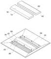
도 1은 본 발명의 일 실시예에 따른 엘이디 조명 장치의 분해 사시도이다.
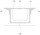
도 2는 도 1에 도시된 엘이디 조명 장치의 결합된 단면을 나타낸 단면도이다.
도 3은 전원공급장치 커버의 조립 과정을 나타낸 분해 사시도이다.
도 4는 전원공급장치 커버의 조립 과정을 나타낸 단면도이다.
도 5는 전원공급장치 커버의 조립된 상태를 나타낸 단면도이다.
도 6은 확산 커버의 조립 과정을 나타낸 분해 사시도이다.
도 7은 확산 커버의 조립된 상태를 나타낸 단면도이다.1 is an exploded perspective view of an LED illumination apparatus according to an embodiment of the present invention.
2 is a cross-sectional view showing a combined cross section of the LED illumination device shown in Fig.
3 is an exploded perspective view showing a process of assembling the power supply cover.
4 is a cross-sectional view showing a process of assembling the power supply cover.
5 is a cross-sectional view showing an assembled state of the power supply cover.
6 is an exploded perspective view showing a process of assembling the diffusion cover.
7 is a cross-sectional view showing an assembled state of the diffusion cover.
상술한 본 발명의 특징 및 효과는 첨부된 도면과 관련한 다음의 상세한 설명을 통하여 보다 분명해 질 것이며, 그에 따라 본 발명이 속하는 기술분야에서 통상의 지식을 가진 자가 본 발명의 기술적 사상을 용이하게 실시할 수 있을 것이다. 본 발명은 다양한 변경을 가할 수 있고 여러 가지 형태를 가질 수 있는 바, 특정 실시예들을 도면에 예시하고 본문에 상세하게 설명하고자 한다. 그러나, 이는 본 발명을 특정한 개시 형태에 대해 한정하려는 것이 아니며, 본 발명의 사상 및 기술 범위에 포함되는 모든 변경, 균등물 내지 대체물을 포함하는 것으로 이해되어야 한다. 본 출원에서 사용한 용어는 단지 특정한 실시예들을 설명하기 위해 사용된 것으로, 본 발명을 한정하려는 의도가 아니다. 단수의 표현은 문맥상 명백하게 다르게 뜻하지 않는 한, 복수의 표현을 포함한다. 본 출원에서, "포함하다" 또는 "가지다" 등의 용어는 명세서에 기재된 특징, 숫자, 단계, 동작, 구성 요소, 부분품 또는 이들을 조합한 것이 존재함을 지정하려는 것이지, 하나 또는 그 이상의 다른 특징들이나 숫자, 단계, 동작, 구성 요소, 부분품 또는 이들을 조합한 것들의 존재 또는 부가 가능성을 미리 배제하지 않는 것으로 이해되어야 한다. 제1, 제2 등의 용어는 다양한 구성 요소들을 설명하는데 사용될 수 있지만, 상기 구성 요소들은 상기 용어들에 의해 한정되어서는 안 된다. 상기 용어들은 하나의 구성 요소를 다른 구성 요소로부터 구별하는 목적으로만 사용된다. 예를 들어, 본 발명의 권리 범위를 벗어나지 않으면서 제1 구성 요소는 제2 구성 요소로 명명될 수 있고, 유사하게 제2 구성 요소도 제1 구성 요소로 명명될 수 있다.
BRIEF DESCRIPTION OF THE DRAWINGS The above and other features and advantages of the present invention will become more apparent from the following detailed description of the present invention when taken in conjunction with the accompanying drawings, It will be possible. The present invention is capable of various modifications and various forms, and specific embodiments are illustrated in the drawings and described in detail in the text. It should be understood, however, that the invention is not intended to be limited to the particular forms disclosed, but includes all modifications, equivalents, and alternatives falling within the spirit and scope of the invention. The terminology used herein is for the purpose of describing particular embodiments only and is not intended to be limiting of the invention. The singular expressions include plural expressions unless the context clearly dictates otherwise. In the present application, the terms "comprising" or "having ", and the like, are intended to specify the presence of stated features, integers, steps, operations, elements, parts, or combinations thereof, But do not preclude the presence or addition of one or more other features, integers, steps, operations, elements, parts, or combinations thereof. The terms first, second, etc. may be used to describe various components, but the components should not be limited by the terms. The terms are used only for the purpose of distinguishing one component from another. For example, without departing from the scope of the present invention, the first component may be referred to as a second component, and similarly, the second component may also be referred to as a first component.
이하, 첨부한 도면들을 참조하여, 본 발명의 바람직한 실시예를 보다 상세하게 설명한다.Hereinafter, preferred embodiments of the present invention will be described in more detail with reference to the accompanying drawings.
도 1은 본 발명의 일 실시예에 따른 엘이디 조명 장치의 분해 사시도이며, 도 2는 도 1에 도시된 엘이디 조명 장치의 결합된 단면을 나타낸 단면도이다.FIG. 1 is an exploded perspective view of an LED illumination device according to an embodiment of the present invention, and FIG. 2 is a cross-sectional view illustrating an assembled cross-section of the LED illumination device shown in FIG.
도 1 및 도 2를 참조하면, 본 발명의 일 실시예에 따른 엘이디 조명 장치는 하우징(100), 히트 싱트(200), 제1 발광모듈(300), 제2 발광모듈(400) 및 전원공급장치(500)를 포함한다. 또한, 엘이디 조명 장치는 전원공급장치(500)를 커버하는 전원공급장치 커버(600)와, 제1 발광모듈(300) 및 제2 발광모듈(400)을 각각 커버하는 제1 확산 커버(700) 및 제2 확산 커버(800)를 포함할 수 있다. 이러한 구조의 엘이디 조명 장치는 실내의 천정면에 매입 설치되어 하방으로 직접 조명을 구현한다.1 and 2, an LED illumination apparatus according to an embodiment of the present invention includes a
하우징(100)은 엘이디 조명 장치의 틀을 형성하는 것으로써, 제1 발광모듈(300) 및 제2 발광모듈(400)로부터 발생된 광을 하방으로 효과적으로 출사시킬 수 있는 구조로 형성된다. 또한, 하우징(100)에는 히트 싱크(200)와의 결합을 위해 상부 중앙에 개구부(110)가 형성될 수 있다. 이와 달리, 하우징(100)의 상부는 막힌 구조로 형성될 수도 있다. 하우징(100)은 제1 발광모듈(300) 및 제2 발광모듈(400)로부터 발생된 광을 하방으로 반사시키기 위하여 반사율이 높은 재질로 형성되거나, 표면에 반사율이 높은 재질이 코팅된 구조를 가질 수 있다.The
하우징(100)은 히트 싱크(200)가 삽입 고정되는 히트 싱크 결합부(120) 및 히트 싱크 결합부(120)로부터 사방으로 경사지게 연장되는 경사부(130)를 포함할 수 있다. 히트 싱크 결합부(120)는 개구부(110)에 삽입된 히트 싱크(200)를 고정시키기 위해 히트 싱크(200)의 네 측면을 둘러싸도록 형성되며, 예를 들어, 스크류 결합을 통해 히트 싱크(200)와 결합된다. 경사부(130)는 히트 싱크 결합부(120)의 하단으로부터 하방 외측으로 경사지게 연장되어 반사갓 역할을 수행한다. 한편, 하우징(100)은 통상의 형광등에 쓰이는 등기구와 유사한 구조로 형성될 수 있으며, 이 외에도 엘이디 조명 장치의 출광 효율을 높이기 위한 다양한 형상 및 구조로 변형될 수 있다.The
히트 싱크(200)는 하우징(100)의 내측에 형성된다. 예를 들어, 히트 싱크(200)는 하우징(100)의 상부 중앙에 형성된 개구부(110)에 삽입 고정된다. 히트 싱크(200)는 제1 발광모듈(300), 제2 발광모듈(400) 및 전원공급장치(500)를 고정시킴과 동시에, 제1 발광모듈(300), 제2 발광모듈(400) 및 전원공급장치(500)로부터 발생되는 열을 외부로 방출시키는 기능을 수행한다.The
히트 싱크(200)는 제1 발광모듈(300), 제2 발광모듈(400) 및 전원공급장치(500)가 결합되는 평판부(210) 및 평판부(210)의 가장자리로부터 수직하게 연장되는 네 개의 측벽부(220)를 포함한다. 측벽부(220)는 하우징(100)의 히트 싱크 결합부(120)와 스크류 체결되며, 평판부(210)의 배면은 방열 효율을 높이기 위해 외부에 노출된다. 히트 싱크(200)는 방열 효율을 높이기 위해 열전도도가 높은 알루미늄(Al)이나 마그네슘(Mg)과 같은 금속 재질로 형성될 수 있다.The
제1 발광모듈(300)은 히트 싱크(200)의 내면 중 제1 영역(R1)에 결합된다. 제2 발광모듈(400)은 히트 싱크(200)의 내면 중 제1 영역(R1)과 소정 거리로 이격된 제2 영역(R2)에 결합된다. 제1 발광모듈(300) 및 제2 발광모듈(400)은 실질적으로 광을 발생시키는 부분으로, 히트 싱크(200)의 평판부(210)에 스크류 체결, 커넥터 체결, 보스 체결 등의 다양한 방식을 통해 고정될 수 있다.The first
제1 발광모듈(300)은 히트 싱크(200)에 결합되는 제1 회로기판(310) 및 제1 회로기판(310)에 실장되어 광을 발생시키는 복수의 제1 발광다이오드들(320)을 포함한다. 제2 발광모듈(400)은 히트 싱크(200)에 결합되는 제2 회로기판(410) 및 제2 회로기판(410)에 실장되어 광을 발생시키는 복수의 제2 발광다이오드들(420)을 포함한다. 제1 발광다이오드들(320) 및 제2 발광다이오드들(420)은 제1 회로기판(310) 및 제2 회로기판(410) 각각의 일면 상에 균일한 분포로 형성된다. 제1 발광다이오드들(320) 및 제2 발광다이오드들(420)은 칩 또는 패키지 형태 모두가 사용될 수 있다.The first
전원공급장치(500)는 제1 발광모듈(300) 및 제2 발광모듈(400)에 구동전원을 공급하기 위한 것으로써, 히트 싱크(200)의 내면 중 제1 영역(R1)과 제2 영역(R2)의 사이인 제3 영역(R3)에 결합된다. 전원공급장치(500)는 외부로부터 인가되는 상용전원(예를 들어, 220V 또는 110V의 교류전원)을 제1 및 제2 발광다이오드들(320, 420)의 구동에 적합한 구동전원(예를 들어, 직류전원)으로 변환하여 출력한다. 예를 들어, 전원공급장치(500)는 SMPS(Switching Mode Power Supply)로 형성된다.The
본 발명에 따르면, 제1 발광모듈(300), 제2 발광모듈(400) 및 전원공급장치(500)는 히트 싱크(200)의 같은 평면(즉, 평판부(210)의 내면) 상에 결합된다. 따라서, 엘이디 조명 장치의 전체 두께를 감소시킬 수 있으며, 전원공급장치(500)의 보수 및 교체를 위해 엘이디 조명 장치 전체를 천정으로부터 분리하거나 또는 천정 안쪽에서 작업을 수행해야 하는 등의 불편함 없이, 엘이디 조명 장치가 천정에 설치되어 있는 상태에서 바로 보수 및 교체 작업을 수행할 수 있는 장점이 있다. 또한, 제1 발광모듈(300) 및 제2 발광모듈(400)은 전원공급장치(500)를 기준으로 양측에 분리되어 배치된다. 제1 발광모듈(300) 및 제2 발광모듈(400)은 광이 소정의 각도로 퍼져 나가는 지향성을 갖기 때문에, 전원공급장치(500)가 중앙부에 배치되어도 엘이디 조명 장치의 하부에서 느끼는 배광 특성에는 별다른 악영향을 미치지 않게 된다. 예를 들어, 엘이디 조명 장치의 배광 특성을 고려하여, 전원공급장치(500)가 형성되는 영역인 상기 제3 영역(R3)의 길이는 제1 영역(R1), 제2 영역(R2) 및 제3 영역(R3)을 모두 합한 전체길이(R1+R2+R3)의 약 30% 이하로 형성되는 것이 바람직하다. 또한, 상기 전원공급장치(500)가 집적화한 IC 형태로 형성된다면, 상기 제3 영역(R3)의 길이는 약 5% 이하로 형성될 수 있다.The first
한편, 엘이디 조명 장치는 전원공급장치(500)를 커버하는 전원공급장치 커버(600)를 더 포함할 수 있다.Meanwhile, the LED illumination device may further include a
도 3은 전원공급장치 커버의 조립 과정을 나타낸 분해 사시도이며, 도 4는 전원공급장치 커버의 조립 과정을 나타낸 단면도이며, 도 5는 전원공급장치 커버의 조립된 상태를 나타낸 단면도이다.FIG. 3 is an exploded perspective view illustrating a process of assembling the power supply cover, FIG. 4 is a cross-sectional view illustrating a process of assembling the power supply cover, and FIG. 5 is a sectional view showing the assembled state of the power supply cover.
도 3, 도 4 및 도 5를 참조하면, 전원공급장치 커버(600)는 히트 싱크(200)의 평판부(210)에 결합되어 전원공급장치(500)를 커버한다.3, 4, and 5, the
전원공급장치 커버(600)는 조립 및 분리의 편의성을 위해 Z-벤딩 방식으로 히트 싱크(200)에 조립될 수 있다. 이를 위해, 히트 싱크(200)는 전원공급장치 커버(600)와의 결합을 위해 평판부(210)에 형성된 복수의 제1 Z-벤딩부(230)를 포함한다. 예를 들어, 제1 Z-벤딩부(230)는 전원공급장치(500)를 기준으로 양측에 각각 하나 이상이 형성된다. 제1 Z-벤딩부(230)는 히트 싱크(200)의 일부를 절개하여 벤딩시킨 것으로써, 전원공급장치(500)와 마주보는 일측이 열려있고, 그 반대측은 막혀있는 구조로 형성된다.The
전원공급장치 커버(600)는 제1 Z-벤딩부(230)와의 결합을 위해 측면의 말단에 형성된 벤딩 결합부(610)를 포함하며, 탄성을 이용하여 히트 싱크(200)의 제1 Z-벤딩부(230)에 결합된다. 즉, 도 4에 도시된 바와 같이, 전원공급장치 커버(600)를 히트 싱크(200)에 결합시키기 위해, 전원공급장치 커버(600)의 측면을 안쪽으로 가압한 상태에서 히트 싱크(200)의 평판부(210)까지 이동시킨 후, 가압력을 풀게 되면 전원공급장치 커버(600)가 갖는 자체적인 탄성력에 의해 측면이 벌어지면서 벤딩 결합부(610)가 제1 Z-벤딩부(230)에 끼워지면서 결합되게 된다. 이때, 벤딩 결합부(610)에는 제1 Z-벤딩부(230)와 대응되는 위치에 결합홀 또는 결합홈이 형성될 수 있다.The
또한, 엘이디 조명 장치는 제1 발광모듈(300) 및 제2 발광모듈(400)을 각각 커버하는 제1 확산 커버(700) 및 제2 확산 커버(800)를 더 포함할 수 있다.The LED illumination device may further include a
도 6은 확산 커버의 조립 과정을 나타낸 분해 사시도이며, 도 7은 확산 커버의 조립된 상태를 나타낸 단면도이다.FIG. 6 is an exploded perspective view showing a process of assembling the diffusion cover, and FIG. 7 is a sectional view showing the assembled state of the diffusion cover.
도 6 및 도 7을 참조하면, 제1 확산 커버(700) 및 제2 확산 커버(800)는 히트 싱크(200) 및 전원공급장치 커버(600)에 결합되어 제1 발광모듈(300) 및 제2 발광모듈(400)을 각각 커버한다. 이에 따라, 제1 확산 커버(700) 및 제2 확산 커버(800)는 전원공급장치 커버(600)를 사이에 두고 서로 이격되게 설치된다. 제1 확산 커버(700) 및 제2 확산 커버(800)는 복수의 발광다이오드들(320, 420)로부터 나오는 점광원 형태의 광을 확산시켜 면광원을 구현하기 위한 것으로써, 엘이디 조명 장치의 외부에서는 발광다이오드들(320, 420)이 보이지 않으면서 엘이디 조명 장치의 전체가 균일한 밝기를 나타낼 수 있도록 확산도가 높은 물질로 형성된다. 제1 확산 커버(700) 및 제2 확산 커버(800)는 합성 수지에 광확산제가 첨가된 구조를 가질 수 있으며, 제1 확산 커버(700) 및 제2 확산 커버(800)의 적어도 일면에는 광 확산을 위한 요철 패턴이 형성된 구조를 가질 수 있다.6 and 7, the
제1 확산 커버(700) 및 제2 확산 커버(800)는 조립 및 분리의 편의성을 위해 Z-벤딩 방식으로 히트 싱크(200) 및 전원공급장치 커버(600)에 결합될 수 있다. 이를 위해, 히트 싱크(200)는 제1 확산 커버(700) 및 제2 확산 커버(800)와의 결합을 위해 측벽부(220)의 내측면에 형성된 제2 Z-벤딩부(240)를 포함할 수 있다. 예를 들어, 제2 Z-벤딩부(240)는 네 개의 측벽부(220)에 각각 하나 이상이 형성된다. 제2 Z-벤딩부(240)는 측벽부(220)의 일부를 절개하여 벤딩시킨 것으로써, 제1 및 제2 확산 커버(700, 800)와 마주보는 일측이 열려있고, 그 반대측은 막혀있는 구조로 형성된다.The
또한, 전원공급장치 커버(600)는 제1 확산 커버(700) 및 제2 확산 커버(800)와의 결합을 위해 외측면에 형성된 제3 Z-벤딩부(620)를 포함할 수 있다. 예를 들어, 제3 Z-벤딩부(620)는 전원공급장치 커버(600)의 양 측면에 각각 하나 이상이 형성된다. 제3 Z-벤딩부(620)는 전원공급장치 커버(600)의 일부를 절개하여 벤딩시킨 것으로써, 제1 및 제2 확산 커버(700, 800)와 마주보는 일측이 열려있고, 그 반대측은 막혀있는 구조로 형성된다.The
제1 확산 커버(700)는 제2 Z-벤딩부(240) 및 제3 Z-벤딩부(620)와 결합되는 제1 확산커버 결합부(710)를 포함하며, 제1 확산 커버(700)의 가압을 통해 제1 확산커버 결합부(710)가 제2 Z-벤딩부(240) 및 제3 Z-벤딩부(620)에 삽입 결합된다. 또한, 제2 확산 커버(800)는 제2 Z-벤딩부(240) 및 제3 Z-벤딩부(620)와 결합되는 제2 확산커버 결합부(810)를 포함하며, 제2 확산 커버(800)의 가압을 통해 제2 확산커버 결합부(810)가 제2 Z-벤딩부(240) 및 제3 Z-벤딩부(620)에 삽입 결합된다. 이때, 제1 확산커버 결합부(710) 및 제2 확산커버 결합부(810)에는 제2 Z-벤딩부(240) 및 제3 Z-벤딩부(620)와 대응되는 위치에 형성된 결합홀 또는 결합홈이 형성될 수 있다.The
이와 같이, 전원공급장치 커버(600), 제1 확산 커버(700) 및 제2 확산 커버(800)를 Z-벤딩 방식을 통해 조립함으로써, 스크류 체결 방식 등의 다른 결합 구조에 비하여 조립 및 분리의 편의성을 향상시킬 수 있다.By assembling the
한편, 도 2를 참조하면, 엘이디 조명 장치의 외관 및 배광 특성을 향상시키기 위하여, 조립이 완료된 전원공급장치 커버(600), 제1 확산 커버(700) 및 제2 확산 커버(800)는 하우징(100)의 경사부(130)의 최하단보다 내측에 위치하도록 형성된다. 또한, 제1 확산 커버(700) 및 제2 확산 커버(800)의 확산면은 전면 조명의 배광 특성을 고려하여 전원공급장치 커버(600)로부터 멀어질수록 높이가 낮아지도록 경사지게 형성된다. 따라서, 본 발명에 따른 엘이디 조명 장치가 천정에 매입 설치될 경우, 실질적인 발광면이 되는 제1 확산 커버(700) 및 제2 확산 커버(800)는 천정면보다 내측에 위치하게 되며, 제1 확산 커버(700) 및 제2 확산 커버(800)로부터 직접 출사되는 광과 하우징(100)의 경사부(130)에 의해 반사되는 광이 합쳐져 전체적으로 균일한 배광특성을 갖는 조명을 구현할 수 있게 된다.2, the
이하, 앞서 설명한 도 1 및 도 7을 참조하여, 본 발명의 바람직한 일 실시예에 따른 엘이디 조명 장치의 제조방법을 설명한다.Hereinafter, with reference to FIGS. 1 and 7, a method of manufacturing an LED illumination device according to a preferred embodiment of the present invention will be described.
도 1 및 도 2를 참조하면, 엘이디 조명 장치의 제조를 위해, 중앙에 개구부(110)가 형성된 하우징(100)의 개구부(110)에 히트 싱크(200)를 삽입 고정시킨다. 예를 들어, 히트 싱크(200)의 측벽부(220)는 하우징(100)의 히트 싱크 결합부(120)와 스크류 체결된다.1 and 2, a
이후, 도 3에 도시된 바와 같이, 히트 싱크(200)의 내면 중 제1 영역(R1)과 제2 영역(R2)의 사이인 제3 영역(R3)에 전원공급장치(500)를 결합한다. 예를 들어, 전원공급장치(500)는 히트 싱크(200)의 제3 영역(R3)에 스크류 체결된다.3, the
이후, 도 4 및 도 5에 도시된 바와 같이, 히트 싱크(200)의 평판부(210)에 전원공급장치(500)를 커버하는 전원공급장치 커버(600)를 결합한다. 예를 들어, 전원공급장치 커버(600)는 탄성을 이용하여 히트 싱크(200)의 제1 Z-벤딩부(230)에 결합된다. 즉, 전원공급장치 커버(600)의 측면을 안쪽으로 가압한 상태에서 히트 싱크(200)의 평판부(210)까지 이동시킨 후, 가압력을 풀게 되면 전원공급장치 커버(600)가 갖는 자체적인 탄성력에 의해 측면이 벌어지면서 벤딩 결합부(610)가 제1 Z-벤딩부(230)에 끼워지면서 결합되게 된다. 이때, 벤딩 결합부(610)에는 제1 Z-벤딩부(230)와 대응되는 위치에 결합홀 또는 결합홈이 형성될 수 있다.4 and 5, the
이후, 도 6에 도시된 바와 같이, 히트 싱크(200)의 내면 중 제1 영역(R1)에 제1 발광모듈(300)을 결합하며, 히트 싱크(200)의 내면 중 제1 영역(R1)과 이격된 제2 영역(R2)에 제2 발광모듈(400)을 결합한다. 예를 들어, 제1 발광모듈(300) 및 제2 발광모듈(400)은 히트 싱크(200)에 스크류 체결된다. 한편, 제1 발광모듈(300) 및 제2 발광모듈(400)은 전원공급장치(500) 및 전원공급장치 커버(600)를 결합하기 전에 히트 싱크(200)에 결합될 수 있다.6, the first
이후, 제1 발광모듈(300) 및 제2 발광모듈(400)을 각각 커버하는 제1 확산 커버(700) 및 제2 확산 커버(800)를 히트 싱크(200) 및 전원공급장치 커버(600)에 결합한다. 예를 들어, 제1 확산 커버(700) 및 제2 확산 커버(800)는 가압을 통해 히트 싱크(200)의 내측면에 형성된 제2 Z-벤딩부(240) 및 전원공급장치 커버(600)의 외측면에 형성된 제3 Z-벤딩부(620)에 삽입 결합된다. 이때, 제1 확산커버 결합부(710) 및 제2 확산커버 결합부(810)에는 제2 Z-벤딩부(240) 및 제3 Z-벤딩부(620)와 대응되는 위치에 형성된 결합홀 또는 결합홈이 형성될 수 있다.The
앞서 설명한 본 발명의 상세한 설명에서는 본 발명의 바람직한 실시예들을 참조하여 설명하였지만, 해당 기술분야의 숙련된 당업자 또는 해당 기술분야에 통상의 지식을 갖는 자라면 후술될 특허청구범위에 기재된 본 발명의 사상 및 기술 영역으로부터 벗어나지 않는 범위 내에서 본 발명을 다양하게 수정 및 변경시킬 수 있음을 이해할 수 있을 것이다.While the present invention has been described in connection with what is presently considered to be practical and exemplary embodiments, it is to be understood that the invention is not limited to the disclosed embodiments, but, on the contrary, It will be understood by those skilled in the art that various changes in form and details may be made therein without departing from the spirit and scope of the invention as defined by the appended claims.
100 : 하우징200 : 히트 싱크
230 : 제1 Z-벤딩부240 : 제2 Z-벤딩부
300 : 제1 발광모듈400 : 제2 발광모듈
500 : 전원공급장치600 : 전원공급장치 커버
620 : 제3 Z-벤딩부700 : 제1 확산 커버
800 : 제2 확산 커버100: housing 200: heat sink
230: first Z-bending portion 240: second Z-bending portion
300: first light emitting module 400: second light emitting module
500: Power supply 600: Power supply cover
620: third Z-bending part 700: first diffusion cover
800: second diffusion cover
Claims (16)
Translated fromKorean상기 하우징의 내측에 형성되는 히트 싱크;
상기 히트 싱크의 내면 중 제1 영역에 결합되는 제1 발광모듈;
상기 히트 싱크의 내면 중 상기 제1 영역과 이격된 제2 영역에 결합되는 제2 발광모듈;
상기 히트 싱크의 내면 중 상기 제1 영역과 상기 제2 영역의 사이인 제3 영역에 결합되어 상기 제1 발광모듈 및 상기 제2 발광모듈에 전원을 공급하는 전원공급장치;
상기 히트 싱크의 상기 제3 영역에 형성되어 상기 전원공급장치를 커버하는 전원공급장치 커버; 및
상기 히트 싱크 및 상기 전원공급장치 커버에 결합되어 상기 제1 발광모듈 및 상기 제2 발광모듈을 각각 커버하는 제1 확산 커버 및 제2 확산 커버를 포함하는 엘이디 조명 장치.housing;
A heat sink formed inside the housing;
A first light emitting module coupled to a first region of the inner surface of the heat sink;
A second light emitting module coupled to a second region of the inner surface of the heat sink spaced apart from the first region;
A power supply unit coupled to a third area between the first area and the second area of the inner surface of the heat sink to supply power to the first light emitting module and the second light emitting module;
A power supply cover formed in the third area of the heat sink and covering the power supply unit; And
And a first diffusion cover and a second diffusion cover which are coupled to the heat sink and the power supply cover and cover the first light emitting module and the second light emitting module, respectively.
상기 제1 발광모듈은 상기 히트 싱크에 결합되는 제1 회로기판 및 상기 제1 회로기판에 실장되는 복수의 제1 발광다이오드들을 포함하며,
상기 제2 발광모듈은 상기 히트 싱크에 결합되는 제2 회로기판 및 상기 제2 회로기판에 실장되는 복수의 제2 발광다이오드들을 포함하는 것을 특징으로 하는 엘이디 조명 장치.The method according to claim 1,
The first light emitting module includes a first circuit board coupled to the heat sink and a plurality of first light emitting diodes mounted on the first circuit board,
Wherein the second light emitting module includes a second circuit board coupled to the heat sink, and a plurality of second light emitting diodes mounted on the second circuit board.
상기 히트 싱크는 상기 전원공급장치 커버와의 결합을 위해 평판부에 형성된 제1 Z-벤딩부를 포함하는 것을 특징으로 하는 엘이디 조명 장치.The method according to claim 1,
Wherein the heat sink includes a first Z-bending portion formed on a flat plate portion for coupling with the power supply cover.
상기 제1 확산 커버와 상기 제2 확산 커버는 상기 전원공급장치 커버를 사이에 두고 서로 이격되게 설치된 것을 특징으로 하는 엘이디 조명 장치.The method according to claim 1,
Wherein the first diffusion cover and the second diffusion cover are spaced apart from each other with the power supply cover therebetween.
상기 히트 싱크는 상기 제1 확산 커버 및 상기 제2 확산 커버와의 결합을 위해 내측면에 형성된 제2 Z-벤딩부를 포함하는 것을 특징으로 하는 엘이디 조명 장치.The method according to claim 1,
Wherein the heat sink includes a second Z-bending portion formed on an inner surface of the heat sink for coupling with the first diffusion cover and the second diffusion cover.
상기 전원공급장치 커버는 상기 제1 확산 커버 및 상기 제2 확산 커버와의 결합을 위해 외측면에 형성된 제3 Z-벤딩부를 포함하는 것을 특징으로 하는 엘이디 조명 장치.The method according to claim 1,
Wherein the power supply cover includes a third Z-bending portion formed on an outer surface for coupling with the first diffusion cover and the second diffusion cover.
상기 히트 싱크가 삽입 고정되는 히트 싱크 결합부; 및
상기 히트 싱크 결합부로부터 사방으로 경사지게 연장되는 경사부를 포함하는 것을 특징으로 하는 엘이디 조명 장치.2. The apparatus of claim 1, wherein the housing
A heat sink coupling portion in which the heat sink is inserted and fixed; And
And an inclined portion extending obliquely from the heat sink connecting portion in all directions.
상기 전원공급장치 커버, 상기 제1 확산 커버 및 상기 제2 확산 커버는 상기 경사부의 하단보다 내측에 위치하는 것을 특징으로 하는 엘이디 조명 장치.10. The method of claim 9,
Wherein the power supply cover, the first diffusion cover, and the second diffusion cover are located inside the lower end of the inclined portion.
상기 제1 확산 커버 및 상기 제2 확산 커버의 확산면은 상기 전원공급장치 커버로부터 멀어질수록 높이가 낮아지도록 경사지게 형성된 것을 특징으로 하는 엘이디 조명 장치.10. The method of claim 9,
Wherein the diffusion surfaces of the first diffusion cover and the second diffusion cover are formed to be inclined so that a height thereof decreases as the distance from the power supply device cover increases.
상기 제3 영역의 길이는 상기 제1 영역, 제2 영역 및 제3 영역을 모두 합한 길이의 30% 이하인 것을 특징으로 하는 엘이디 조명 장치.The method according to claim 1,
Wherein the length of the third region is equal to or less than 30% of the total length of the first region, the second region, and the third region.
상기 히트 싱크의 내면 중 제1 영역에 제1 발광모듈을 결합하는 단계;
상기 히트 싱크의 내면 중 상기 제1 영역과 이격된 제2 영역에 제2 발광모듈을 결합하는 단계;
상기 히트 싱크의 내면 중 상기 제1 영역과 상기 제2 영역의 사이인 제3 영역에 상기 제1 발광모듈 및 상기 제2 발광모듈에 전원을 공급하는 전원공급장치를 결합하는 단계;
상기 히트 싱크에 상기 전원공급장치를 커버하는 전원공급장치 커버를 결합하는 단계; 및
상기 제1 발광모듈 및 상기 제2 발광모듈을 각각 커버하는 제1 확산 커버 및 제2 확산 커버를 상기 히트 싱크 및 상기 전원공급장치 커버에 결합하는 단계를 포함하는 엘이디 조명 장치의 제조방법.Fixing the heat sink to the upper center of the housing;
Coupling a first light emitting module to a first region of the inner surface of the heat sink;
Coupling a second light emitting module to a second region of the inner surface of the heat sink spaced apart from the first region;
Coupling a power supply device for supplying power to the first light emitting module and the second light emitting module in a third region of the inner surface of the heat sink between the first region and the second region;
Coupling a power supply cover covering the power supply to the heat sink; And
And coupling a first diffusion cover and a second diffusion cover to the heat sink and the power supply cover, the first diffusion cover and the second diffusion cover covering the first light emitting module and the second light emitting module, respectively.
상기 전원공급장치 커버는 탄성을 이용하여 상기 히트 싱크의 평판부에 형성된 제1 Z-벤딩부에 결합되는 것을 특징으로 하는 엘이디 조명 장치의 제조방법.15. The method of claim 14,
Wherein the power supply cover is coupled to a first Z-bending portion formed on a flat plate portion of the heat sink using elasticity.
상기 제1 확산 커버 및 상기 제2 확산 커버는 상기 히트 싱크의 내측면에 형성된 제2 Z-벤딩부 및 상기 전원공급장치 커버의 외측면에 형성된 제3 Z-벤딩부에 삽입 결합되는 것을 특징으로 하는 엘이디 조명 장치의 제조방법.15. The method of claim 14,
Wherein the first diffusion cover and the second diffusion cover are inserted and coupled to a second Z-bending portion formed on an inner surface of the heat sink and a third Z-bending portion formed on an outer surface of the power supply cover, Of the light emitting device.
Priority Applications (4)
| Application Number | Priority Date | Filing Date | Title |
|---|---|---|---|
| KR1020120087152AKR101404302B1 (en) | 2012-08-09 | 2012-08-09 | Led illumination apparatus and mathod of manufacturing the same |
| US13/919,328US20140043827A1 (en) | 2012-08-09 | 2013-06-17 | Led lighting apparatus |
| PCT/KR2013/005299WO2014025134A1 (en) | 2012-08-09 | 2013-06-17 | Led lighting apparatus |
| CN201380040595.7ACN104508366A (en) | 2012-08-09 | 2013-06-17 | LED lighting |
Applications Claiming Priority (1)
| Application Number | Priority Date | Filing Date | Title |
|---|---|---|---|
| KR1020120087152AKR101404302B1 (en) | 2012-08-09 | 2012-08-09 | Led illumination apparatus and mathod of manufacturing the same |
Publications (2)
| Publication Number | Publication Date |
|---|---|
| KR20140021189A KR20140021189A (en) | 2014-02-20 |
| KR101404302B1true KR101404302B1 (en) | 2014-06-05 |
Family
ID=50267728
Family Applications (1)
| Application Number | Title | Priority Date | Filing Date |
|---|---|---|---|
| KR1020120087152AExpired - Fee RelatedKR101404302B1 (en) | 2012-08-09 | 2012-08-09 | Led illumination apparatus and mathod of manufacturing the same |
Country Status (1)
| Country | Link |
|---|---|
| KR (1) | KR101404302B1 (en) |
Cited By (1)
| Publication number | Priority date | Publication date | Assignee | Title |
|---|---|---|---|---|
| KR102333645B1 (en)* | 2021-07-27 | 2021-12-02 | (주)문화전기 | A LED lighting system with easy angle adjustment |
Families Citing this family (1)
| Publication number | Priority date | Publication date | Assignee | Title |
|---|---|---|---|---|
| KR102029674B1 (en)* | 2018-04-27 | 2019-10-08 | (주)미승 | Led lighting apparatus |
Citations (4)
| Publication number | Priority date | Publication date | Assignee | Title |
|---|---|---|---|---|
| KR20100113440A (en)* | 2009-04-08 | 2010-10-21 | 주식회사 지엘비젼 | Led lighting with broad and uniform light distribution |
| KR20110123989A (en)* | 2010-05-10 | 2011-11-16 | 주식회사 인성전자 | LED module lamp |
| KR101103519B1 (en)* | 2010-04-10 | 2012-01-09 | 엘지이노텍 주식회사 | Lighting device |
| JP2012104485A (en)* | 2010-11-12 | 2012-05-31 | Lg Innotek Co Ltd | Lighting device |
- 2012
- 2012-08-09KRKR1020120087152Apatent/KR101404302B1/ennot_activeExpired - Fee Related
Patent Citations (4)
| Publication number | Priority date | Publication date | Assignee | Title |
|---|---|---|---|---|
| KR20100113440A (en)* | 2009-04-08 | 2010-10-21 | 주식회사 지엘비젼 | Led lighting with broad and uniform light distribution |
| KR101103519B1 (en)* | 2010-04-10 | 2012-01-09 | 엘지이노텍 주식회사 | Lighting device |
| KR20110123989A (en)* | 2010-05-10 | 2011-11-16 | 주식회사 인성전자 | LED module lamp |
| JP2012104485A (en)* | 2010-11-12 | 2012-05-31 | Lg Innotek Co Ltd | Lighting device |
Cited By (1)
| Publication number | Priority date | Publication date | Assignee | Title |
|---|---|---|---|---|
| KR102333645B1 (en)* | 2021-07-27 | 2021-12-02 | (주)문화전기 | A LED lighting system with easy angle adjustment |
Also Published As
| Publication number | Publication date |
|---|---|
| KR20140021189A (en) | 2014-02-20 |
Similar Documents
| Publication | Publication Date | Title |
|---|---|---|
| JP6345749B2 (en) | Lighting device | |
| JP5641804B2 (en) | Lighting device | |
| US9857069B2 (en) | Spherical lamp with easy heat dissipation | |
| KR101195745B1 (en) | Led lamp | |
| KR101826946B1 (en) | A led candle lamp | |
| KR101305007B1 (en) | Assembly structure for led lamp | |
| CN101614367B (en) | Light-emitting diode lamp | |
| KR101369422B1 (en) | Light emitting diode lighting lamp | |
| KR101102455B1 (en) | LED lighting fixtures | |
| KR101140174B1 (en) | A direct-type LED lighting instrument | |
| JP5732613B2 (en) | lighting equipment | |
| KR200458200Y1 (en) | Cover floating LED ceiling that is hard to disassemble | |
| KR100945175B1 (en) | Led lighting apparatus | |
| KR101404302B1 (en) | Led illumination apparatus and mathod of manufacturing the same | |
| KR100936783B1 (en) | Led lighting apparatus | |
| KR20130052796A (en) | A led lighting apparatus | |
| KR20130079005A (en) | Led fluorescent apparatus for pendant type | |
| CN103016973B (en) | Ligthing paraphernalia | |
| KR101848801B1 (en) | Lighting device | |
| KR101357322B1 (en) | Led illumination apparatus | |
| KR100945173B1 (en) | Led lighting apparatus | |
| KR101652783B1 (en) | Lighting device | |
| KR101633311B1 (en) | Multi-Surface Lighting Plate Lamp having LED | |
| KR20110011847A (en) | Panel-integrated lighting without glare | |
| KR101341084B1 (en) | Light emitting diode downlight |
Legal Events
| Date | Code | Title | Description |
|---|---|---|---|
| PA0109 | Patent application | St.27 status event code:A-0-1-A10-A12-nap-PA0109 | |
| A201 | Request for examination | ||
| PA0201 | Request for examination | St.27 status event code:A-1-2-D10-D11-exm-PA0201 | |
| R17-X000 | Change to representative recorded | St.27 status event code:A-3-3-R10-R17-oth-X000 | |
| PG1501 | Laying open of application | St.27 status event code:A-1-1-Q10-Q12-nap-PG1501 | |
| E902 | Notification of reason for refusal | ||
| PE0902 | Notice of grounds for rejection | St.27 status event code:A-1-2-D10-D21-exm-PE0902 | |
| E13-X000 | Pre-grant limitation requested | St.27 status event code:A-2-3-E10-E13-lim-X000 | |
| P11-X000 | Amendment of application requested | St.27 status event code:A-2-2-P10-P11-nap-X000 | |
| P13-X000 | Application amended | St.27 status event code:A-2-2-P10-P13-nap-X000 | |
| E701 | Decision to grant or registration of patent right | ||
| GRNT | Written decision to grant | ||
| PE0701 | Decision of registration | St.27 status event code:A-1-2-D10-D22-exm-PE0701 | |
| PR0701 | Registration of establishment | St.27 status event code:A-2-4-F10-F11-exm-PR0701 | |
| PR1002 | Payment of registration fee | St.27 status event code:A-2-2-U10-U11-oth-PR1002 Fee payment year number:1 | |
| PG1601 | Publication of registration | St.27 status event code:A-4-4-Q10-Q13-nap-PG1601 | |
| P22-X000 | Classification modified | St.27 status event code:A-4-4-P10-P22-nap-X000 | |
| P22-X000 | Classification modified | St.27 status event code:A-4-4-P10-P22-nap-X000 | |
| R18-X000 | Changes to party contact information recorded | St.27 status event code:A-5-5-R10-R18-oth-X000 | |
| PR1001 | Payment of annual fee | St.27 status event code:A-4-4-U10-U11-oth-PR1001 Fee payment year number:4 | |
| P22-X000 | Classification modified | St.27 status event code:A-4-4-P10-P22-nap-X000 | |
| LAPS | Lapse due to unpaid annual fee | ||
| PC1903 | Unpaid annual fee | St.27 status event code:A-4-4-U10-U13-oth-PC1903 Not in force date:20180530 Payment event data comment text:Termination Category : DEFAULT_OF_REGISTRATION_FEE | |
| P22-X000 | Classification modified | St.27 status event code:A-4-4-P10-P22-nap-X000 | |
| PC1903 | Unpaid annual fee | St.27 status event code:N-4-6-H10-H13-oth-PC1903 Ip right cessation event data comment text:Termination Category : DEFAULT_OF_REGISTRATION_FEE Not in force date:20180530 | |
| R18-X000 | Changes to party contact information recorded | St.27 status event code:A-5-5-R10-R18-oth-X000 | |
| R18-X000 | Changes to party contact information recorded | St.27 status event code:A-5-5-R10-R18-oth-X000 |