KR101403681B1 - Loop antenna - Google Patents
Loop antennaDownload PDFInfo
- Publication number
- KR101403681B1 KR101403681B1KR1020100050170AKR20100050170AKR101403681B1KR 101403681 B1KR101403681 B1KR 101403681B1KR 1020100050170 AKR1020100050170 AKR 1020100050170AKR 20100050170 AKR20100050170 AKR 20100050170AKR 101403681 B1KR101403681 B1KR 101403681B1
- Authority
- KR
- South Korea
- Prior art keywords
- pattern
- loop
- region
- loop antenna
- outer pattern
- Prior art date
- Legal status (The legal status is an assumption and is not a legal conclusion. Google has not performed a legal analysis and makes no representation as to the accuracy of the status listed.)
- Expired - Fee Related
Links
Images


Classifications
- H—ELECTRICITY
- H01—ELECTRIC ELEMENTS
- H01Q—ANTENNAS, i.e. RADIO AERIALS
- H01Q7/00—Loop antennas with a substantially uniform current distribution around the loop and having a directional radiation pattern in a plane perpendicular to the plane of the loop
- H—ELECTRICITY
- H01—ELECTRIC ELEMENTS
- H01Q—ANTENNAS, i.e. RADIO AERIALS
- H01Q1/00—Details of, or arrangements associated with, antennas
- H01Q1/52—Means for reducing coupling between antennas; Means for reducing coupling between an antenna and another structure
Landscapes
- Details Of Aerials (AREA)
Abstract
Translated fromKoreanDescription
Translated fromKorean본 발명은 루프 안테나에 관한 것으로서, 보다 상세하게는 루프 형태를 갖는 외부 패턴의 내부 영역에, 내부 패턴을 형성하는 루프 안테나에 관한 것이다.BACKGROUND OF THE INVENTION Field of the Invention The present invention relates to a loop antenna, and more particularly, to a loop antenna that forms an internal pattern in an inner region of an outer pattern having a loop shape.
근거리 무선 통신은 하루가 다르게 발전하고 있다. 특히, 근거리 무선 통신의 일 예인, RFID를 이용한 통신을 이용하면, 자재 관리, 교통 카드, 물품 구매 등 다양한 분야에서 사용자의 편의를 도모할 수 있다.Short-range wireless communication is evolving one day differently. Particularly, when communication using RFID, which is one example of short-range wireless communication, is used, convenience of users can be improved in various fields such as material management, traffic card, and article purchase.
RFID 통신을 위해서는 RFID 용 안테나가 필요하며, RFID 용 안테나로서 루프 안테나가 널리 이용되고 있다.An RFID antenna is required for RFID communication, and a loop antenna is widely used as an antenna for RFID.
루프 안테나는 루프의 크기가 크면 클수록 방사 성능이 향상된다. 따라서, 루프 안테나의 사이즈도 함께 커지게 된다.The larger the loop size of the loop antenna, the better the radiation performance. Therefore, the size of the loop antenna also increases.
이와 같은 구조상의 특성에 따라, 루프 안테나의 내부 영역은 사용하지 않는 영역으로 인식되어 왔다. 하지만, 최근 다양한 모바일 기기들이 경량화 및 소형화되어 가고 있는 경향과 함께, 루프 안테나에 대해서도 그 사이즈는 줄이면서도 성능을 향상시킬 필요성이 있다.
According to such a structural characteristic, the inner region of the loop antenna has been recognized as an unused region. However, in recent years, various mobile devices have been becoming lighter and smaller, and there is a need to improve the performance of the loop antenna while reducing its size.
본 발명은 상술한 필요성에 따라 안출된 것으로서, 루프 형태를 갖는 외부 패턴의 내부 영역에, 외부 패턴과 반대 방향으로 전류가 흐르는 내부 패턴을 형성하는 루프 안테나를 제공하는데 그 목적이 있다.It is an object of the present invention to provide a loop antenna which forms an inner pattern in which an electric current flows in a direction opposite to an outer pattern in an inner region of an outer pattern having a loop shape.
본 발명의 일 실시 예에 따른 루프 안테나는, 기판, 상기 기판 표면상에서 루프를 형성하는 외부 패턴, 및 상기 외부 패턴이 형성하는 루프의 내부 영역에 배치되며, 일 단이 상기 외부 패턴의 일단과 연결된 내부 패턴을 포함하며, 상기 내부 패턴은, 상기 외부 패턴에서의 전류 방향과 반대로 전류가 흐르는 형태일 수 있다.A loop antenna according to an embodiment of the present invention includes a substrate, an outer pattern forming a loop on the substrate surface, and an inner region of a loop formed by the outer pattern, wherein one end is connected to one end of the outer pattern And the internal pattern may be a form in which current flows in a direction opposite to the current direction in the external pattern.
상기 내부 패턴은, 복수 개의 곡점을 갖는 바(bar) 형태일 수 있다.The inner pattern may be in the form of a bar having a plurality of curves.
상기 복수 개의 곡점은, 7개일 수 있다.The number of the plurality of curves may be seven.
상기 내부 패턴은, 나선 형태일 수 있다.The internal pattern may be in the form of a spiral.
상기 외부 패턴은, 사각 형태의 복수 개의 루프를 포함하며, 상기 복수 개의 루프 각각은, 모따기(chamfering)된 형상의 모서리를 가질 수 있다.The outer pattern includes a plurality of loops in a rectangular shape, and each of the plurality of loops may have chamfers of chamfered shapes.
상기 외부 패턴은, 상기 복수 개의 루프 중 가장 내측에 형성된 루프의 일 단 및 타 단이 상기 내부 영역으로 각각 돌출연장될 수 있다.In the outer pattern, one end and the other end of the loop formed at the innermost of the plurality of loops may protrude from the inner region.
상기 일 단까지 돌출연장된 루프 및 상기 타 단까지 돌출연장된 루프는 서로 나란하게 배치될 수 있다.The protruding extended loop to the one end and the protruded extended loop to the other end may be arranged side by side.
상기 내부 패턴은, 상기 외부 패턴과 대응되는 형태를 갖는 제1 영역 및 상기 제1 영역과 연결되며, 상기 내부 영역의 중앙 방향으로 돌출연장된 제2 영역을 포함할 수 있다.The inner pattern may include a first region having a shape corresponding to the outer pattern, and a second region connected to the first region and protruding and extending toward the center of the inner region.
상기 제1 영역은, 상기 외부 패턴과 기설정된 간격으로 나란하게 이격 배치될 수 있다.The first region may be spaced apart from the outer pattern at predetermined intervals.
상기 제1 영역은, 모따기된 형상의 2개의 모서리를 포함할 수 있다.The first region may include two corners of the chamfered shape.
상기 루프의 타 단에 전원을 인가하는 급전부를 더 포함할 수 있다.And a power feeder for applying power to the other end of the loop.
상기 내부 패턴은, "G" 형태일 수 있다.The internal pattern may be in the "G" form.
상기 루프 안테나는, 13.56 Mhz의 주파수에서 동작할 수 있다.The loop antenna may operate at a frequency of 13.56 Mhz.
도 1은 본 발명의 일 실시 예에 따른 루프 안테나를 나타내는 도면.
도 2는 본 루프 안테나의 동작 원리를 나타내는 도면.
도 3 및 도 4는 내부 패턴의 일 예를 나타내는 도면.
도 5는 일반적인 루프 안테나의 동작 특성을 나타내는 그래프.
도 6은 본 루프 안테나의 동작 특성을 나타내는 그래프.1 shows a loop antenna according to an embodiment of the present invention;
2 is a view showing an operation principle of the present loop antenna.
Figs. 3 and 4 are diagrams showing an example of an internal pattern. Fig.
5 is a graph showing the operating characteristics of a typical loop antenna.
6 is a graph showing the operating characteristics of the present loop antenna.
이하 도면을 참조하여 본 발명에 대하여 보다 상세하게 살펴보기로 한다.BRIEF DESCRIPTION OF THE DRAWINGS FIG.
도 1은 본 발명의 일 실시 예에 따른 루프 안테나를 나타내는 도면이다.1 is a view illustrating a loop antenna according to an embodiment of the present invention.
도 1을 참조하면, 본 발명의 일 실시 예에 따른 루프 안테나(100)는 기판(110), 외부 패턴(120), 내부 패턴(130), 급전부(140), 및 매칭부(150)를 포함한다.1, a
기판(110)은, 표면에 외부 패턴(120), 내부 패턴(130), 급전부(140), 및 매칭부(150)와 같은 도체 패턴이 형성된다. 기판(110)은 실리콘(Si)과 같은 절연 물질로 이루어진다.The
외부 패턴(120)은 기판(110)의 표면에서 루프를 형성한다.The
외부 패턴(120)은 기판(110)의 표면을 에칭하거나, 기판(110)의 표면에 도전성 잉크를 이용한 프린팅 방법 등으로 형성될 수 있다.The
외부 패턴(120)은 금, 은 구리, 알루미늄, 스테인리스 스틸 및 그 합금, 은 도금된 구리, 및 주석 도금된 구리 등과 같은 도전성 물질로 이루어질 수 있다.The
외부 패턴(120)에 형성된 루프는 복수 개의 루프를 갖는다. 복수 개의 루프는 서로 기설정된 간격으로 이격되어 배치된다.The loop formed in the
도 1에서는, 외부 패턴(120)이 4개의 루프를 가지는 것으로 도시되어 있지만, 복수 개의 루프를 갖는 것이라면 그 개수에 한정되지 않는다.In FIG. 1, the
외부 패턴(120)의 복수 개의 루프가 기판(110)의 가장 자리에 형성됨에 따라, 기판(110)의 중앙에는 내부 영역이 정의될 수 있다. 내부 영역에는 후술할 내부 패턴(130)이 형성될 수 있다.As a plurality of loops of the
또한, 도 1에서는, 외부 패턴(120)이 사각 형태를 갖는 것으로 도시되어 있으나, 루프 안테나(100)가 사용되는 용도에 따라 원형, 타원형, 및 다각형 중 어느 하나일 수도 있다.1, the
외부 패턴(120)은 전체적으로 사각 형태이며, 각 모서리가 모따기(chamfering)된 형태를 갖는다. 모따기된 각도는 45%인 것이 바람직하다.The
외부 패턴(120)의 복수 개의 루프 중 가장 내측에 형성된 루프의 일 단(A)은 내부 패턴(130)의 일 단과 연결된다.One end (A) of the innermost loop of the plurality of loops of the
복수 개의 루프 중 가장 내측에 형성된 루프의 일 단(A) 및 타 단은 기판(110)의 가장자리에서 기판(110)의 내부 영역으로 각각 돌출연장(projected and extended)된다. One end (A) and the other end of the innermost loop of the plurality of loops are projected and extended from the edge of the
일 단(A)까지 돌출연장된 루프와 타 단까지 돌출연장된 루프는 서로 나란하게 배치되는 것이 바람직하다.It is preferable that the protruding and extending loops extending to the one end A and the protruding and extending loops extending to the other end are arranged side by side.
복수 개의 루프 중 가장 내측에 배치된 일 단(B)은 기판(110)의 이면을 통해 가장 외 측에 배치된 일 단(C)과 연결된다.One end (B) of the plurality of loops arranged at the innermost side is connected to one end (C) disposed on the outermost side through the back surface of the substrate (110).
내부 패턴(130)은 외부 패턴(120)이 형성하는 루프의 내부 영역에 배치된다. 내부 패턴(130)의 일단은 외부 패턴(120)의 일 단(A)과 연결된다. 내부 패턴(130)의 타 단은 외부 패턴(120)과 이격되어 내부 영역에 배치된다.The
내부 패턴(130)도 외부 패턴(120)에서 상술한 것과 같은 방법으로 형성될 수 있으며, 외부 패턴(120)에서 상술한 것과 같은 물질로 이루어질 수 있다.The
내부 패턴(130)은, 일 단이 외부 패턴(120)에 연결되고, 타 단이 외부 패턴(120)과 이격되기만 하면, 다양한 형태를 가질 수 있다.The
일 예로서, 내부 패턴(130)은 나선 형태이거나, 도 1에서 도시된 것처럼 알파벳 "G" 형태 또는 좌우 회전된 알파벳 "G" 형태일 수도 있다. 다만, 도 1에서 도시된 형태에 한정되지 않는다.As an example, the
내부 패턴(130)은 외부 패턴(120)에서의 전류와 반대 방향의 전류가 흐른다.The
내부 패턴(130)은 외부 패턴(120)의 형상과 동일한 형상을 갖는 것이 바람직하다. 일 예로서, 외부 패턴(120)이 사각 형태이면, 내부 패턴도 사각 형태인 것이 바람직하며, 외부 패턴(120)이 원형이면, 내부 패턴도 원형인 것이 바람직하다. 즉, 내부 패턴(130)이 외부 패턴(120)과 전체적으로 대응되는 구조를 갖거나, 일부분이 대응되는 구조를 가질 수 있다.The
급전부(140)는 무선 주파수 신호 또는 고주파수 신호와 같은 신호가 공급될 수 있다. 또한, 급전부(140)는, 코일 등을 포함할 수 있으며, 도시된 것과 달리, 기판(110) 표면의 일 영역 또는 기판(110)의 이면에 배치되어 공급되는 전기 신호를 무선 충전할 수 있다.The
매칭부(150)는 인덕턴스 성분 및 커패시턴스 성분을 가변하여 임피던스 매칭을 수행한다. 구체적으로, 매칭부(150)는 본 루프 안테나(100)가 13. 56 MHz의 공진 주파수에서 동작할 수 있도록 임피던스 매칭을 수행할 수 있다.The
한편, 본 루프 안테나(100)는 13. 56 MHz에서 동작하는 RFID 근거리 무선 통신에 이용될 수 있다. 이에 따라, E-Book, RFID 태그 등과 같은 다양한 RFID 어플리케이션에 높은 성능을 갖는 루프 안테나(100)를 제공할 수 있다.Meanwhile, the
도 2는 본 루프 안테나의 동작 원리를 나타내는 도면이다.Fig. 2 is a view showing the operation principle of the present loop antenna.
도 2를 참조하면, 급전부(140)를 통해 입력된 신호는 외부 패턴(120)의 복수 개의 루프를 회전하면서, 전기장을 생성한다.Referring to FIG. 2, a signal input through the
외부 패턴(120)에는 도시된 화살표 방향, 즉 반시계 방향으로 전류가 흐를 수 있으며, 내부 패턴(130)에는 도시된 화살표 방향, 즉 시계 방향으로 전류가 흐를 수 있다.A current can flow in the
이와 같이, 본 루프 안테나(100)는 외부패턴(120) 및 내부 패턴(130)에 흐르는 전류의 방향이 서로 반대이며, 내부 패턴(130)과 외부 패턴(120)이 기설정된 간격을 가지고 나란하게 배치될 수 있게 되므로, 내부 패턴(130), 외부 패턴(120), 및 내부 패턴(130)과 외부 패턴(120) 사이의 기판(110)에 의해 기생 커패시턴스(또는, 기생 인덕턴스)가 발생할 수 있으며, 발생한 기생 커패시턴스(또는, 기생 인덕턴스)에 의해 루프 안테나(100)의 공진 특성, 즉 성능이 더욱 향상될 수 있다.The
도 3 및 도 4는 내부 패턴의 일 예를 나타내는 도면이다.3 and 4 are views showing an example of an internal pattern.
도 3을 참조하면, 내부 패턴(130)은, 복수 개의 곡점(또는 곡부)을 갖는 바(bar) 형태일 수 있다. 여기서, 곡점은 직선 형태의 바의 방향이 변하는 지점이며, 절곡(折曲)점일 수 있다.Referring to FIG. 3, the
복수 개의 곡점은, 도시된 것처럼 제1 곡점(C1), 제2 곡점(C2), 제3 곡점(C3), 제4 곡점(C4), 제5 곡점(C5), 제6 곡점(C6), 및 제7 곡점(C7)과 같이 7개인 것이 바람직하다.The plurality of curved points include a first curved point C1, a second curved point C2, a third curved point C3, a fourth curved point C4, a fifth curved point C5, a sixth curved point C6, And the seventh curved point (C7).
도 3에서는 2개의 모따기(chamfering)된 형상을 갖는 모서리가 도시되어 있으나, 도시된 것과 달리, 내부 패턴(130)은 2개의 모따기(chamfering)된 형상을 갖지 않고, 5개의 곡점을 갖는 바 형태일 수도 있다.In FIG. 3, two chamfered corners are shown, but unlike the
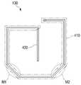
도 4를 참조하면, 내부 패턴(130)은 제1 영역(410) 및 제1 영역(410)을 포함한다.Referring to FIG. 4, the
제1 영역(410)은 외부 패턴(120)과 대응되는 형태를 가지며, 제1 영역(410)의 일 단은 제2 영역의 일 단과 연결된다. 제1 영역(410)은, 외부 패턴(120)과 기설정된 간격으로 나란하게 이격 배치될 수 있다. 제1 영역(410)은 모따기된 형상의 2개의 모서리를 포함할 수 있다.The
제2 영역(420)은 외부 패턴(120)과 대응되지 않지만, 내부 영역의 중앙 방향으로 돌출연장된다.The
본 루프 안테나(100)는 가로 및 세로의 크기가 각각 대략 4 cm일 수 있으며, 내부 패턴(130)(보다 구체적으로는, 제1 영역(410))과 외부 패턴 사이(120)의 간격은 대략 3~5 mm 사이인 것이 바람직하다.The
도 5는 일반적인 루프 안테나의 동작 특성을 나타내는 그래프이며, 도 6은 본 루프 안테나의 동작 특성을 나타내는 그래프이다FIG. 5 is a graph showing the operating characteristics of a conventional loop antenna, and FIG. 6 is a graph showing operating characteristics of the present loop antenna
루프 안테나의 동작 특성은 전기장보다 자기장에 더 영향을 받기 때문에, 도 5 및 도 6에서는 H-Field 특성에 대하여 살펴보기로 한다.Since the operating characteristics of the loop antenna are more affected by the magnetic field than the electric field, the H-field characteristics will be examined in FIGS. 5 and 6. FIG.
도 5를 참조하면, 일반적인 루프 안테나의 경우, H-Field beam peak 값이 대략 4.8 A/m인 반면에, 본 루프 안테나의 경우 H-Field beam peak 값이 대략 7.5 A/m임을 알 수 있다.Referring to FIG. 5, the H-field beam peak value of the general loop antenna is approximately 4.8 A / m while the H-field beam peak value of the present loop antenna is approximately 7.5 A / m.
이와 같이, 루프 안테나(100)의 내부 영역에 외부 패턴(120)과 반대 방향으로 전류가 흐르는 내부 패턴(130)이 형성되기 때문에, 내부 영역에서 방사되는 에너지가 가장자리 방향으로 이동하여, H-Field의 빔 피크값이 현저히 개선된다.Since the
또한, 동일한 H-Field 값, 일 예로서 3 A/m에서의 대역폭도 증가한다.In addition, the same H-Field value, for example, the bandwidth at 3 A / m, also increases.
즉, H-Field의 빔 피크값이 현저히 개선되며, 대역폭이 증가하기 때문에 루프 안테나(100)의 동작 특성이 향상된다. 이에 따라, 본 루프 안테나(100)는 동일한 안테나의 체적(사이즈)에 대하여 더 개선된 성능을 갖는다.That is, the beam peak value of the H-field is remarkably improved, and the operating characteristic of the
이상에서는 본 발명의 바람직한 실시 예에 대하여 도시하고 설명하였지만, 당해 발명이 속하는 기술분야에서 통상의 지식을 가진 자라면, 누구든지 본 발명의 기술적 사상 및 범위를 벗어나지 않는 범주 내에서 본 발명의 바람직한 실시 예를 다양하게 변경할 수 있음은 물론이다. 따라서 본 발명은 특허청구범위에서 청구하는 본 발명의 요지를 벗어나지 않는다면 다양한 변형 실시가 가능할 것이며, 이러한 변형 실시들은 본 발명의 기술적 사상이나 전망으로부터 개별적으로 이해되어져서는 안될 것이다.While the present invention has been particularly shown and described with reference to exemplary embodiments thereof, it is clearly understood that the same is by way of illustration and example only and is not to be taken by way of illustration, It goes without saying that the example can be variously changed. Accordingly, it is intended that the present invention cover the modifications and variations of this invention provided they come within the scope of the appended claims and their equivalents. * * * * * Recently Added Patents
100 : 루프 안테나110 : 기판
120 : 외부 패턴130 : 내부 패턴
140 : 급전부150 : 매칭부100: loop antenna 110: substrate
120: outer pattern 130: inner pattern
140: feeding part 150: matching part
Claims (13)
Translated fromKorean상기 기판 표면상에서 루프를 형성하는 외부 패턴; 및
상기 외부 패턴이 형성하는 루프의 내부 영역에 배치되며, 일 단이 상기 외부 패턴의 일단과 연결된 내부 패턴;을 포함하며,
상기 내부 패턴은, 상기 외부 패턴에서의 전류 방향과 반대로 전류가 흐르고, 복수 개의 곡점을 갖는 바(bar) 형태인 것을 특징으로 하는 루프 안테나.Board;
An outer pattern forming a loop on the substrate surface; And
And an inner pattern disposed in an inner region of the loop formed by the outer pattern and having one end connected to one end of the outer pattern,
Wherein the inner pattern is in the form of a bar having a plurality of curved points through which a current flows inversely to a current direction in the outer pattern.
상기 복수 개의 곡점은, 7개인 것을 특징으로 하는 루프 안테나.The method according to claim 1,
And said plurality of curves are seven.
상기 내부 패턴은, 나선 형태인 것을 특징으로 하는 루프 안테나.The method according to claim 1,
Wherein the inner pattern is a spiral shape.
상기 외부 패턴은, 사각 형태의 복수 개의 루프를 포함하며,
상기 복수 개의 루프 각각은, 모따기(chamfering)된 형상의 모서리를 갖는 것을 특징으로 하는 루프 안테나.The method according to claim 1,
Wherein the outer pattern includes a plurality of loops in a rectangular shape,
Wherein each of the plurality of loops has an edge of a chamfered shape.
상기 외부 패턴은, 상기 복수 개의 루프 중 가장 내측에 형성된 루프의 일 단 및 타 단이 상기 내부 영역으로 각각 돌출연장된 것을 특징으로 하는 루프 안테나.6. The method of claim 5,
Wherein the outer pattern is formed such that one end and the other end of the loop formed on the innermost side of the plurality of loops protrude from the inner region.
상기 일 단까지 돌출연장된 루프 및 상기 타 단까지 돌출연장된 루프는 서로 나란하게 배치된 것을 특징으로 하는 루프 안테나.The method according to claim 6,
Wherein the loop extending to one end and the loop extending to the other end are arranged in parallel with each other.
상기 내부 패턴은, 상기 외부 패턴과 대응되는 형태를 갖는 제1 영역 및 상기 제1 영역과 연결되며, 상기 내부 영역의 중앙 방향으로 돌출연장된 제2 영역을 포함하는 것을 특징으로 하는 루프 안테나.6. The method of claim 5,
Wherein the inner pattern includes a first region having a shape corresponding to the outer pattern, and a second region connected to the first region and extending in a central direction of the inner region.
상기 제1 영역은,
상기 외부 패턴과 기설정된 간격으로 나란하게 이격 배치되는 것을 특징으로 하는 루프 안테나.9. The method of claim 8,
Wherein the first region comprises:
And wherein the loop antenna is spaced apart from the external pattern at predetermined intervals.
상기 제1 영역은, 모따기된 형상의 2개의 모서리를 포함하는 것을 특징으로 하는 루프 안테나.9. The method of claim 8,
Wherein the first region comprises two corners of the chamfered shape.
상기 루프의 타 단에 전원을 인가하는 급전부;를 더 포함하는 것을 특징으로 하는 루프 안테나.The method according to claim 1,
And a power feeder for applying power to the other end of the loop.
상기 내부 패턴은, "G" 형태인 것을 특징으로 하는 루프 안테나.The method according to claim 1,
Wherein the internal pattern is a "G" shape.
상기 루프 안테나는,
13.56 Mhz의 주파수에서 동작하는 것을 특징으로 하는 루프 안테나.The method according to claim 1,
The loop antenna includes:
Lt; RTI ID = 0.0 > 13.56 Mhz. ≪ / RTI >
Priority Applications (3)
| Application Number | Priority Date | Filing Date | Title |
|---|---|---|---|
| KR1020100050170AKR101403681B1 (en) | 2010-05-28 | 2010-05-28 | Loop antenna |
| US13/012,383US8599094B2 (en) | 2010-05-28 | 2011-01-24 | Loop antenna |
| EP11166800AEP2390956A1 (en) | 2010-05-28 | 2011-05-19 | Loop antenna |
Applications Claiming Priority (1)
| Application Number | Priority Date | Filing Date | Title |
|---|---|---|---|
| KR1020100050170AKR101403681B1 (en) | 2010-05-28 | 2010-05-28 | Loop antenna |
Publications (2)
| Publication Number | Publication Date |
|---|---|
| KR20110130704A KR20110130704A (en) | 2011-12-06 |
| KR101403681B1true KR101403681B1 (en) | 2014-06-09 |
Family
ID=44501847
Family Applications (1)
| Application Number | Title | Priority Date | Filing Date |
|---|---|---|---|
| KR1020100050170AExpired - Fee RelatedKR101403681B1 (en) | 2010-05-28 | 2010-05-28 | Loop antenna |
Country Status (3)
| Country | Link |
|---|---|
| US (1) | US8599094B2 (en) |
| EP (1) | EP2390956A1 (en) |
| KR (1) | KR101403681B1 (en) |
Families Citing this family (7)
| Publication number | Priority date | Publication date | Assignee | Title |
|---|---|---|---|---|
| US20090159682A1 (en)* | 2007-12-24 | 2009-06-25 | Dynamics Inc. | Cards and devices with multi-function magnetic emulators and methods for using same |
| KR101400623B1 (en)* | 2012-12-07 | 2014-05-29 | 광운대학교 산학협력단 | Single layer nfc antenna |
| US9293825B2 (en)* | 2013-03-15 | 2016-03-22 | Verifone, Inc. | Multi-loop antenna system for contactless applications |
| US20150054704A1 (en)* | 2013-08-23 | 2015-02-26 | Samsung Sdi Co., Ltd. | Antenna module for terminal device and method for manufacturing the same |
| KR101467706B1 (en)* | 2013-11-21 | 2014-12-01 | 광운대학교 산학협력단 | The improved NFC antenna structure for reducing the proximity effect due to the coupled current loops |
| TWI509891B (en)* | 2013-11-22 | 2015-11-21 | Wistron Neweb Corp | Loop antenna |
| JP6865125B2 (en)* | 2017-07-05 | 2021-04-28 | 日本発條株式会社 | Data reader |
Citations (3)
| Publication number | Priority date | Publication date | Assignee | Title |
|---|---|---|---|---|
| KR20060131905A (en)* | 2004-02-20 | 2006-12-20 | 쓰리엠 이노베이티브 프로퍼티즈 컴파니 | Multi-loop antenna for radio frequency identification (RRFF) communication |
| KR20070007343A (en)* | 2004-03-23 | 2007-01-15 | 쓰리엠 이노베이티브 프로퍼티즈 컴파니 | RFID tag with compensation elements |
| KR20090061152A (en)* | 2007-12-11 | 2009-06-16 | (주)케이티에프테크놀로지스 | Loop antenna |
Family Cites Families (9)
| Publication number | Priority date | Publication date | Assignee | Title |
|---|---|---|---|---|
| US5248989A (en)* | 1988-02-04 | 1993-09-28 | Unisan Ltd. | Magnetic field concentrator |
| US5508710A (en) | 1994-03-11 | 1996-04-16 | Wang-Tripp Corporation | Conformal multifunction shared-aperture antenna |
| JP3337865B2 (en) | 1995-04-22 | 2002-10-28 | ソニーケミカル株式会社 | Synthetic loop antenna |
| JP3528367B2 (en) | 1995-09-30 | 2004-05-17 | ソニーケミカル株式会社 | Antenna for reader / writer |
| US5914692A (en)* | 1997-01-14 | 1999-06-22 | Checkpoint Systems, Inc. | Multiple loop antenna with crossover element having a pair of spaced, parallel conductors for electrically connecting the multiple loops |
| GB9718311D0 (en)* | 1997-08-30 | 1997-11-05 | Hately Maurice C | Dual loop radio antenna |
| JP3481575B2 (en)* | 2000-09-28 | 2003-12-22 | 寛児 川上 | antenna |
| US6597318B1 (en) | 2002-06-27 | 2003-07-22 | Harris Corporation | Loop antenna and feed coupler for reduced interaction with tuning adjustments |
| US6970141B2 (en) | 2003-07-02 | 2005-11-29 | Sensormatic Electronics Corporation | Phase compensated field-cancelling nested loop antenna |
- 2010
- 2010-05-28KRKR1020100050170Apatent/KR101403681B1/ennot_activeExpired - Fee Related
- 2011
- 2011-01-24USUS13/012,383patent/US8599094B2/enactiveActive
- 2011-05-19EPEP11166800Apatent/EP2390956A1/ennot_activeWithdrawn
Patent Citations (3)
| Publication number | Priority date | Publication date | Assignee | Title |
|---|---|---|---|---|
| KR20060131905A (en)* | 2004-02-20 | 2006-12-20 | 쓰리엠 이노베이티브 프로퍼티즈 컴파니 | Multi-loop antenna for radio frequency identification (RRFF) communication |
| KR20070007343A (en)* | 2004-03-23 | 2007-01-15 | 쓰리엠 이노베이티브 프로퍼티즈 컴파니 | RFID tag with compensation elements |
| KR20090061152A (en)* | 2007-12-11 | 2009-06-16 | (주)케이티에프테크놀로지스 | Loop antenna |
Also Published As
| Publication number | Publication date |
|---|---|
| US8599094B2 (en) | 2013-12-03 |
| KR20110130704A (en) | 2011-12-06 |
| US20110291912A1 (en) | 2011-12-01 |
| EP2390956A1 (en) | 2011-11-30 |
Similar Documents
| Publication | Publication Date | Title |
|---|---|---|
| KR101403681B1 (en) | Loop antenna | |
| US9010648B2 (en) | Antenna and RFID tag | |
| WO2010050278A1 (en) | Radio communication device | |
| US20060038724A1 (en) | Small planar antenna with enhanced bandwidth and small rectenna for RFID and wireless sensor transponder | |
| JP2007249620A (en) | Wireless tag | |
| JP2007013981A (en) | Internal chip antenna | |
| US10135152B2 (en) | Antenna device and electronic device | |
| JP6193612B2 (en) | Antenna and manufacturing method thereof | |
| JP2009065321A (en) | Patch antenna | |
| JP5416773B2 (en) | Dipole antenna | |
| US20090179800A1 (en) | Antenna structure | |
| JP2012231219A (en) | Plate-like inverse f antenna | |
| JP6229814B2 (en) | Communication terminal device | |
| CN109390682A (en) | Super antenna | |
| US9768505B2 (en) | MIMO antenna with no phase change | |
| JP4413698B2 (en) | Ring antenna with parasitic element | |
| CN104681988B (en) | near field communication antenna | |
| CN112106253B (en) | Configurable multi-band linear antenna device and design method thereof | |
| JP5187083B2 (en) | RFID tag, RFID system, and RFID tag manufacturing method | |
| JP4675940B2 (en) | Integrated antenna | |
| TW201234712A (en) | Low impedance slot fed antenna | |
| JP4775390B2 (en) | Reader / writer | |
| KR20160121279A (en) | multi antenna unit and wireless charging module having the same | |
| JP2008060899A (en) | ANTENNA DEVICE AND ELECTRONIC DEVICE USING THE SAME | |
| JP5370141B2 (en) | Antenna device |
Legal Events
| Date | Code | Title | Description |
|---|---|---|---|
| PA0109 | Patent application | St.27 status event code:A-0-1-A10-A12-nap-PA0109 | |
| PG1501 | Laying open of application | St.27 status event code:A-1-1-Q10-Q12-nap-PG1501 | |
| R18-X000 | Changes to party contact information recorded | St.27 status event code:A-3-3-R10-R18-oth-X000 | |
| A201 | Request for examination | ||
| PA0201 | Request for examination | St.27 status event code:A-1-2-D10-D11-exm-PA0201 | |
| D13-X000 | Search requested | St.27 status event code:A-1-2-D10-D13-srh-X000 | |
| D14-X000 | Search report completed | St.27 status event code:A-1-2-D10-D14-srh-X000 | |
| E902 | Notification of reason for refusal | ||
| PE0902 | Notice of grounds for rejection | St.27 status event code:A-1-2-D10-D21-exm-PE0902 | |
| E13-X000 | Pre-grant limitation requested | St.27 status event code:A-2-3-E10-E13-lim-X000 | |
| P11-X000 | Amendment of application requested | St.27 status event code:A-2-2-P10-P11-nap-X000 | |
| P13-X000 | Application amended | St.27 status event code:A-2-2-P10-P13-nap-X000 | |
| E701 | Decision to grant or registration of patent right | ||
| PE0701 | Decision of registration | St.27 status event code:A-1-2-D10-D22-exm-PE0701 | |
| GRNT | Written decision to grant | ||
| PR0701 | Registration of establishment | St.27 status event code:A-2-4-F10-F11-exm-PR0701 | |
| PR1002 | Payment of registration fee | St.27 status event code:A-2-2-U10-U11-oth-PR1002 Fee payment year number:1 | |
| PG1601 | Publication of registration | St.27 status event code:A-4-4-Q10-Q13-nap-PG1601 | |
| FPAY | Annual fee payment | Payment date:20170427 Year of fee payment:4 | |
| PR1001 | Payment of annual fee | St.27 status event code:A-4-4-U10-U11-oth-PR1001 Fee payment year number:4 | |
| FPAY | Annual fee payment | Payment date:20180427 Year of fee payment:5 | |
| PR1001 | Payment of annual fee | St.27 status event code:A-4-4-U10-U11-oth-PR1001 Fee payment year number:5 | |
| LAPS | Lapse due to unpaid annual fee | ||
| PC1903 | Unpaid annual fee | St.27 status event code:A-4-4-U10-U13-oth-PC1903 Not in force date:20190529 Payment event data comment text:Termination Category : DEFAULT_OF_REGISTRATION_FEE | |
| PC1903 | Unpaid annual fee | St.27 status event code:N-4-6-H10-H13-oth-PC1903 Ip right cessation event data comment text:Termination Category : DEFAULT_OF_REGISTRATION_FEE Not in force date:20190529 |