KR101401280B1 - Slim enclosure speaker with side accoustic emission - Google Patents
Slim enclosure speaker with side accoustic emissionDownload PDFInfo
- Publication number
- KR101401280B1 KR101401280B1KR1020130036162AKR20130036162AKR101401280B1KR 101401280 B1KR101401280 B1KR 101401280B1KR 1020130036162 AKR1020130036162 AKR 1020130036162AKR 20130036162 AKR20130036162 AKR 20130036162AKR 101401280 B1KR101401280 B1KR 101401280B1
- Authority
- KR
- South Korea
- Prior art keywords
- speaker
- upper case
- cover
- case
- lower case
- Prior art date
- Legal status (The legal status is an assumption and is not a legal conclusion. Google has not performed a legal analysis and makes no representation as to the accuracy of the status listed.)
- Expired - Fee Related
Links
Images


Classifications
- H—ELECTRICITY
- H04—ELECTRIC COMMUNICATION TECHNIQUE
- H04R—LOUDSPEAKERS, MICROPHONES, GRAMOPHONE PICK-UPS OR LIKE ACOUSTIC ELECTROMECHANICAL TRANSDUCERS; DEAF-AID SETS; PUBLIC ADDRESS SYSTEMS
- H04R9/00—Transducers of moving-coil, moving-strip, or moving-wire type
- H04R9/02—Details
- H—ELECTRICITY
- H04—ELECTRIC COMMUNICATION TECHNIQUE
- H04R—LOUDSPEAKERS, MICROPHONES, GRAMOPHONE PICK-UPS OR LIKE ACOUSTIC ELECTROMECHANICAL TRANSDUCERS; DEAF-AID SETS; PUBLIC ADDRESS SYSTEMS
- H04R1/00—Details of transducers, loudspeakers or microphones
- H04R1/02—Casings; Cabinets ; Supports therefor; Mountings therein
- H04R1/025—Arrangements for fixing loudspeaker transducers, e.g. in a box, furniture
- H—ELECTRICITY
- H04—ELECTRIC COMMUNICATION TECHNIQUE
- H04R—LOUDSPEAKERS, MICROPHONES, GRAMOPHONE PICK-UPS OR LIKE ACOUSTIC ELECTROMECHANICAL TRANSDUCERS; DEAF-AID SETS; PUBLIC ADDRESS SYSTEMS
- H04R1/00—Details of transducers, loudspeakers or microphones
- H04R1/02—Casings; Cabinets ; Supports therefor; Mountings therein
- H04R1/021—Casings; Cabinets ; Supports therefor; Mountings therein incorporating only one transducer
- H—ELECTRICITY
- H04—ELECTRIC COMMUNICATION TECHNIQUE
- H04R—LOUDSPEAKERS, MICROPHONES, GRAMOPHONE PICK-UPS OR LIKE ACOUSTIC ELECTROMECHANICAL TRANSDUCERS; DEAF-AID SETS; PUBLIC ADDRESS SYSTEMS
- H04R1/00—Details of transducers, loudspeakers or microphones
- H04R1/02—Casings; Cabinets ; Supports therefor; Mountings therein
- H—ELECTRICITY
- H04—ELECTRIC COMMUNICATION TECHNIQUE
- H04R—LOUDSPEAKERS, MICROPHONES, GRAMOPHONE PICK-UPS OR LIKE ACOUSTIC ELECTROMECHANICAL TRANSDUCERS; DEAF-AID SETS; PUBLIC ADDRESS SYSTEMS
- H04R2201/00—Details of transducers, loudspeakers or microphones covered by H04R1/00 but not provided for in any of its subgroups
- H04R2201/02—Details casings, cabinets or mounting therein for transducers covered by H04R1/02 but not provided for in any of its subgroups
- H04R2201/029—Manufacturing aspects of enclosures transducers
Landscapes
- Physics & Mathematics (AREA)
- Engineering & Computer Science (AREA)
- Acoustics & Sound (AREA)
- Signal Processing (AREA)
- Details Of Audible-Bandwidth Transducers (AREA)
Abstract
Translated fromKoreanDescription
Translated fromKorean본 발명은 슬림형 측면 방사 인클로져 스피커에 관한 것이다.The present invention relates to a slim lateral radiating enclosure speaker.
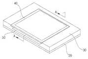
도 1은 종래 기술에 따른 슬림형 측면 방사 인클로져 스피커의 분해 사시도, 도 2는 종래 기술에 따른 슬림형 측면 방사 인클로져 스피커의 사시도, 도 3은 도 2를 A-A' 선을 따라 절단한 단면도이다.FIG. 1 is an exploded perspective view of a conventional slim side radiating enclosure speaker, FIG. 2 is a perspective view of a conventional slim side radiating enclosure speaker, and FIG. 3 is a sectional view taken along line A-A 'of FIG.
종래 기술에 따른 슬림형 측면 방사 인클로져 스피커는 마이크로스피커(10), 하부 케이스(20), 상부 케이스(30), 상부 케이스(30) 상에 결합되는 커버(40)를 포함한다. 하부 케이스(20)의 중앙부는 SUS 재질로 이루어지는 얇은 스틸부(26)가 사출 성형되며, 사출부는 스틸부(26)보다 두꺼운 두께로 이루어져 스틸부(26)와 단차를 형성하는 하면(24)과, 측면을 둘러싸는 측벽(22)을 포함한다.The slim side-surface radiation enclosure speaker according to the prior art includes a
상부 케이스(30)는 하부 케이스(20)의 상부에 결합되며, 하부 케이스(20) 측벽(22) 상에 결합되는 측벽(32)과, 마이크로스피커(10)가 고정되는 고정면(34), 커버(40)를 결합하기 위한 안착단(36)을 포함하는 상면을 구비한다. 상부 케이스(30)의 일 측에는 측벽(32)과 안착단(36)을 일부 삭제하는 대신, 고정면(34)과 이어지는 경사면(38)과 경사면(38) 외측의 수평면(39)을 포함한다. 상부 케이스(30)의 상부에 커버(40)가 결합되면, 커버(40)와, 경사면(38) 및 수평면(39) 사이의 공간이 음향이 방출되는 음향 통로(50)가 된다.The
일반적으로 소리의 크기는 dB(데시벨)로 표기를 하며, 스피커 시스템에서는 음압레벨(SPL, Sound Pressure Level) 또는 능률이라고 표기를 하게 된다. 이 뜻은 ‘앰프에서 1와트(2.83v)의 출력을 스피커에 보내줄 때 스피커에서 1m 떨어진 곳에서 들을 수 있는 평균적인 소리의 크기’라는 뜻이다. 따라서 음압이 크면 클수록 동일한 앰프의 출력으로도 보다 큰 소리가 재생된다.In general, the size of the sound is expressed in dB (decibel), and in the speaker system, the sound pressure level (SPL) or efficiency is indicated. This means 'the average amount of sound you can hear at 1 meter from the speaker when you send a 1 watt (2.83v) output from the amplifier to the speaker'. Therefore, the larger the sound pressure, the louder the sound reproduced by the output of the same amplifier.
도 1 내지 도 3과 같은 종래 슬림형 측면 방사 인클로져 스피커는 소리가 나가는 관로가 좁아지면서 저음역에 음압이 낮아지게 된다. 비교적 진폭이 큰 저음역에서는 공기를 밀어주는 양이 많아지는데, 좁은 관로를 통해 나가려면 저항력이 높아져 저음특성이 나빠지게 된다. 따라서 인클로져 스피커를 슬림화하기 위해 방음구의 크기를 줄이는 경우, 저음에서의 SPL이 낮아지게 된다. 따라서 인클로져 스피커는 슬림화하되, 동일 사이즈 내에서 방음구를 최대화하는 기술이 요구된다.The conventional slim side radiating enclosure loudspeaker as shown in Figs. 1 to 3 has a narrow sound path, so that the sound pressure is lowered in the low frequency range. In a bass region with a relatively large amplitude, the amount of pushing the air is increased. In order to pass through the narrow channel, resistance becomes higher and the bass characteristic deteriorates. Therefore, when the size of the soundproofing sphere is reduced in order to slim the enclosure speaker, the SPL at the low sound is lowered. Therefore, it is required to make the enclosure speaker slimmer, and to maximize the soundproofing within the same size.
본 발명은 동일한 크기 내에서 방음구를 최대화하여, 측면 방사 인클로져 스피커를 슬림화하는 동시에, SPL 특성을 향상시킬 수 있는 슬림형 측면 방사 인클로져 스피커를 제공하는 것을 목적으로 한다.It is an object of the present invention to provide a slim side-surface radiation enclosure speaker capable of maximizing soundproofing within the same size, thereby slimming the side-radiating enclosure speaker and improving SPL characteristics.
본 발명은 마이크로스피커, 마이크로스피커의 하부를 감싸며, 공명공간을 정의하는 하부 케이스, 마이크로스피커의 상면 테두리가 고정되는 고정면을 구비하며, 하부 케이스와 함께 공명 공간을 정의하며, 가압면 내측에 홀이 형성된 상부 케이스, 상부 케이스의 상부에 결합되며 홀을 덮는 커버 및 상부 케이스의 일 측과 커버에 의해 정의되는 음향 통로를 포함하며, 고정면은 스틸로 인서트 사출된 것을 특징으로 하는 슬림형 측면 방사 인클로져 스피커를 제공한다.The present invention relates to a micro speaker, a lower case which surrounds a lower portion of a micro speaker, a lower case which defines a resonance space, a fixing surface on which a top edge of the micro speaker is fixed, a resonance space together with the lower case, And a sound path defined by one side of the upper case and a cover coupled to an upper portion of the upper case and covering the hole, the fixing surface being insert-injected with steel, characterized in that the slim side surface radiation enclosure Provides a speaker.
또한 본 발명의 다른 일 예로, 하부 케이스의 중앙부 및 커버의 중앙부는 각각 인서트 사출되는 스틸부로 이루어지며, 사출부보다 얇은 두께로 이루어져 단차를 이루는 것을 특징으로 하는 슬림형 측면 방사 인클로져 스피커를 제공한다.According to another embodiment of the present invention, the central portion of the lower case and the central portion of the cover each include a steel portion injected with an insert, and the thickness of the steel portion is thinner than that of the injection portion to form a step.
또한 본 발명의 다른 일 예로, 하부 케이스의 스틸부와 마이크로스피커 사이에 공명공간이 형성되는 것을 특징으로 하는 슬림형 측면 방사 인클로져 스피커를 제공한다.In another aspect of the present invention, a resonance space is formed between a steel portion of a lower case and a micro-speaker, thereby providing a slim side-surface radiation enclosure speaker.
또한 본 발명의 다른 일 예로, 마이크로스피커는 상부 케이스의 고정면에 본딩 접착되는 것을 특징으로 하는 슬림형 측면 방사 인클로져 스피커를 제공한다.According to another aspect of the present invention, there is provided a slim side-surface radiation enclosure speaker characterized in that a micro-speaker is bonded and bonded to a fixing surface of an upper case.
또한 본 발명의 다른 일 예로, 상부 케이스와 하부 케이스의 결합 및 상부 케이스와 커버의 결합은 본딩 접착 또는 초음파 융착에 의해 이루어지는 것을 특징으로 하는 슬림형 측면 방사 인클로져 스피커를 제공한다.According to another aspect of the present invention, there is provided a slim side-surface radiation enclosure speaker characterized in that the coupling of the upper case and the lower case and the coupling of the upper case and the cover are performed by bonding bonding or ultrasonic welding.
또한 본 발명의 다른 일 예로, 마이크로스피커를 상부 케이스의 고정면에 본딩 접착하고, 상부 케이스와 하부 케이스를 초음파 융착시킨 다음, 커버를 상부 케이스에 본딩 접착함으로써 제조되는 것을 특징으로 하는 슬림형 측면 방사 인클로져 스피커를 제공한다.According to another embodiment of the present invention, the micro speaker is manufactured by bonding and bonding the micro speaker to the fixing surface of the upper case, ultrasonic welding the upper case and the lower case, and then bonding and bonding the cover to the upper case. Provides a speaker.
본 발명이 제공하는 슬림형 측면 방사 인클로져 스피커는, 인클로져 케이스에서 마이크로스피커를 고정하는 부분을 얇으면서도 강성을 가지는 스틸로 대체함으로써 음향 통로의 크기를 최대화할 수 있다.The slim side side radiation enclosure speaker provided by the present invention can maximize the size of the acoustic path by replacing the portion fixing the micro speaker in the enclosure case with thin and rigid steel.
도 1은 종래 기술에 따른 슬림형 측면 방사 인클로져 스피커의 분해 사시도,
도 2는 종래 기술에 따른 슬림형 측면 방사 인클로져 스피커의 사시도,
도 3은 도 2를 A-A' 선을 따라 절단한 단면도,
도 4는 본 발명의 일 실시예에 따른 슬림형 측면 방사 인클로져 스피커의 분해 사시도,
도 5는 본 발명의 일 실시예에 따른 슬림형 측면 방사 인클로져 스피커의 사시도,
도 6은 도 5를 B-B' 선을 따라 절단한 단면도,
도 7은 본 발명의 일 실시예에 따른 슬림형 측면 방사 인클로져 스피커를 조립하는 방법을 개략적으로 도시한 도면.FIG. 1 is an exploded perspective view of a conventional slim side radiating enclosure speaker,
FIG. 2 is a perspective view of a conventional slim side radiating enclosure speaker,
FIG. 3 is a cross-sectional view taken along line AA 'of FIG. 2,
4 is an exploded perspective view of a slim side radiating enclosure speaker according to an embodiment of the present invention,
5 is a perspective view of a slim side radiating enclosure speaker according to an embodiment of the present invention,
FIG. 6 is a cross-sectional view taken along line BB 'of FIG. 5,
7 is a schematic view illustrating a method of assembling a slim side-surface radiation enclosure speaker according to an embodiment of the present invention.
이하 도면을 참조하여 본 발명을 더욱 상세하게 설명한다.BEST MODE FOR CARRYING OUT THE INVENTION Hereinafter, the present invention will be described in detail with reference to the drawings.
도 4는 본 발명의 일 실시예에 따른 슬림형 측면 방사 인클로져 스피커의 분해 사시도, 도 5는 본 발명의 일 실시예에 따른 슬림형 측면 방사 인클로져 스피커의 사시도, 도 6은 도 5를 B-B' 선을 따라 절단한 단면도이다.FIG. 4 is an exploded perspective view of a slim side-surface radiation enclosure speaker according to an embodiment of the present invention, FIG. 5 is a perspective view of a slim side-surface radiation enclosure speaker according to an embodiment of the present invention, and FIG. Fig.
본 발명의 일 실시예에 따른 슬림형 측면 방사 인클로져 스피커는 마이크로스피커(100), 하부 케이스(200), 상부 케이스(300), 상부 케이스(300) 상에 결합되는 커버(400)를 포함한다. 상부 케이스(300)의 일 측 상부에는 커버(400)와의 결합 시에 음향 통로(600)가 형성되도록 오목한 형상이 구비된다. 이 오목한 형상은 후술할 경사면(380)과 수평면(390)이다.The slim side radiating enclosure speaker according to an embodiment of the present invention includes a
하부 케이스(200)는 사출물로 이루어지는 측벽(220)과 하면(240)으로 이루어지며, 하면(240)의 중앙에는 얇은 SUS 재질의 스틸부(260)가 하부 케이스(200)의 사출 성형 시에 인서트 사출된다.The
상부 케이스(300)는 하부 케이스(200)의 상부에 결합되어 공명 공간(500)을 형성하며, 하부 케이스(200) 측벽(220) 상에 결합되는 측벽(320)과, 마이크로스피커(100)가 고정되는 고정면(340), 커버(400)를 결합하기 위한 안착단(360)을 포함하는 상면을 구비한다. 고정면(340)의 내측에는 홀(350)이 형성되며, 커버(400)가 고정면(340)의 내측에 형성된 홀(350)과 경사면(380) 및 수평면(390)을 덮어주는 형태이다. 상부 케이스(300)는 고정면(340)을 제외하고는 사출물로 이루어지며, 고정면(340)은 SUS 스틸 재질로 형성되어 종래 기술에 비해 얇으면서도 충분한 강성을 가지도록 할 수 있다. 예를 들어 도 1 내지 도 3에 도시된 상부 케이스(30)의 고정면(34)은 다른 부분과 마찬가지로 사출물로 이루어지므로, 0.4T 내외의 두께를 가져야 했으며, 그러한 두께를 가지는 경우에도 강성이 충분하지 못해 파단될 우려가 있었다. 반면 본원 발명의 일 실시예와 같이 고정면(340)이 스틸로 인서트 사출 성형될 경우, 0.1T의 두께로도 충분한 강성을 가질 수 있다.The
상부 케이스(300)의 상부는, 인서트 사출 시에 고정면(340)을 상, 하부에서 덮어주는 사출고정부(342)를 포함한다. 또한 상부 케이스(300)의 상부는 홀(350)과 경사면(380) 및 수평면(390)을 덮어주는 커버(400)를 안착하기 위한 안착단(360)을 포함한다. 홀(350) 및 커버(400)는 전체적으로 사각형이며, 안착단(360)은 상술한 음향 통로(600)를 형성하기 위해 마련된 경사면(380)과 수평면(390)을 가로지르지 않도록 음향 통로(600) 측을 제외하고, 커버(400)의 세 모서리를 지지할 수 있도록 "ㄷ"자 형상으로 형성된다. 안착단(360)의 세 모서리는 서로 마주보는 두 모서리와, 이에 수직인 하나의 모서리로 이루어진다. 각각 상부 케이스(300)의 모서리와 소정 간격을 두고 형성되는데, 서로 마주보는 두 모서리는 일 단부가 상부 케이스(300)의 단부까지 연장된다. 이는 커버(400)가 홀(350)을 덮어줄 뿐만 아니라, 경사면(380) 및 수평면(390)을 덮어주어야 하기 때문이며, 경사면(380) 및 수평면(390)을 포함하는 오목한 부분과 커버(400)에 의해 음향 통로(600)가 형성되기 때문이다. 즉, 안착단(360)에서 마주보는 두 모서리는 각각, 경사면(380)과 수평면(390)의 일측까지 연장된다.The upper portion of the
상부 케이스(300)의 일 측에는 하부로 오목하게 들어간 경사면(380)과 경사면(380) 외측의 수평면(390)을 포함한다. 상부 케이스(300)의 상부에 커버(400)가 결합되면, 커버(400)와, 경사면(380) 및 수평면(390) 사이의 공간이 음향이 방출되는 음향 통로(600)가 된다.One side of the
따라서, 전체적인 인클로져 스피커의 크기가 동일할 때 커버(400)와 고정면(340) 사이의 간격이 클수록 음향 통로(600)의 크기가 커진다고 볼 수 있다. 본원 발명에 따른 고정면(340)은 인서트 사출된 스틸로 형성되어 얇으면서도 충분한 강성을 지니도록 할 수 있다.Accordingly, it can be seen that the larger the distance between the
커버(400) 역시 중앙은 스틸부(440)로 하고 그 외의 부분은 사출부(420)로 함으로써, 음향 통로(600)의 크기를 더욱 키울 수 있다. 또한 고정면(340)을 스틸로 형성하면서 얇아진 두께만큼, 안착부(360) 상에 맞닿는 안착단(460)을 다른 사출부(420)보다 높게 형성함으로써 전체적인 인클로져 스피커의 크기는 동일하되, 음향 통로(600)의 크기를 키울 수 있다.The size of the
도 7은 본 발명의 일 실시예에 따른 슬림형 측면 방사 인클로져 스피커를 조립하는 방법을 개략적으로 도시한 도면이다. 먼저, 마이크로스피커(100)를 상부 케이스(300)의 고정면(340; 도 4 참조)의 하면에 본드로 접착한다. 그 다음, 상부 케이스(300)와 하부 케이스(200)를 서로 결합시킨다. 상부 케이스(300)와 하부 케이스(200)는 본드로 접착되거나, 초음파 융착에 의해 접착된다. 다음으로 상부 케이스(300)의 안착단(360; 도 4 참조)에 커버(400)를 결합한다. 커버(400)는 본드를 이용해 접착된다.7 is a schematic view illustrating a method of assembling a slim side radiating enclosure speaker according to an embodiment of the present invention. First, the
Claims (6)
Translated fromKorean마이크로스피커의 하부를 감싸며, 공명공간을 정의하는 하부 케이스;
마이크로스피커의 상면 테두리가 고정되는 고정면을 구비하며, 하부 케이스와 함께 공명 공간을 정의하며, 가압면 내측에 홀이 형성된 상부 케이스;
상부 케이스의 상부에 결합되며 홀을 덮는 커버; 및
상부 케이스의 일 측과 커버에 의해 정의되는 음향 통로;를 포함하며,
고정면은 스틸로 인서트 사출된 것을 특징으로 하는 슬림형 측면 방사 인클로져 스피커.Micro speaker;
A lower case surrounding the lower portion of the micro speaker and defining a resonance space;
An upper case having a fixing surface on which an upper surface of the micro speaker is fixed and defining a resonance space together with the lower case and having a hole formed inside the pressing surface;
A cover coupled to an upper portion of the upper case and covering the hole; And
An acoustic path defined by one side of the upper case and a cover,
And the fixing surface is insert-injected with steel.
하부 케이스의 중앙부 및 커버의 중앙부는 각각 인서트 사출되는 스틸부로 이루어지며, 사출부보다 얇은 두께로 이루어져 단차를 이루는 것을 특징으로 하는 슬림형 측면 방사 인클로져 스피커.The method according to claim 1,
Wherein the central portion of the lower case and the central portion of the cover are made of a steel portion injected through an insert and each have a thickness smaller than that of the injection portion to form a step.
하부 케이스의 스틸부와 마이크로스피커 사이에 공명공간이 형성되는 것을 특징으로 하는 슬림형 측면 방사 인클로져 스피커.3. The method of claim 2,
And a resonance space is formed between the steel portion of the lower case and the micro-speaker.
마이크로스피커는 상부 케이스의 고정면에 본딩 접착되는 것을 특징으로 하는 슬림형 측면 방사 인클로져 스피커.The method according to claim 1,
And the micro speaker is bonded and bonded to the fixing surface of the upper case.
상부 케이스와 하부 케이스의 결합 및 상부 케이스와 커버의 결합은 본딩 접착 또는 초음파 융착에 의해 이루어지는 것을 특징으로 하는 슬림형 측면 방사 인클로져 스피커.The method according to claim 1,
Wherein the coupling of the upper case and the lower case and the coupling of the upper case and the cover are performed by bonding or ultrasonic welding.
마이크로스피커를 상부 케이스의 고정면에 본딩 접착하고, 상부 케이스와 하부 케이스를 초음파 융착시킨 다음, 커버를 상부 케이스에 본딩 접착함으로써 제조되는 것을 특징으로 하는 슬림형 측면 방사 인클로져 스피커.The method according to claim 1,
Bonding the micro speaker to the fixing surface of the upper case, ultrasonic welding the upper case and the lower case, and bonding the cover to the upper case.
Priority Applications (4)
| Application Number | Priority Date | Filing Date | Title |
|---|---|---|---|
| KR1020130036162AKR101401280B1 (en) | 2013-04-03 | 2013-04-03 | Slim enclosure speaker with side accoustic emission |
| EP14000644.6AEP2787744B1 (en) | 2013-04-03 | 2014-02-24 | Slim enclosure speaker with side acoustic emission structure |
| CN201410111198.0ACN104105014B (en) | 2013-04-03 | 2014-03-24 | Thin encapsulation formula loudspeaker with sidepiece sound emission structure |
| US14/230,567US20140301587A1 (en) | 2013-04-03 | 2014-03-31 | Slim enclosure speaker with side acoustic emission structure |
Applications Claiming Priority (1)
| Application Number | Priority Date | Filing Date | Title |
|---|---|---|---|
| KR1020130036162AKR101401280B1 (en) | 2013-04-03 | 2013-04-03 | Slim enclosure speaker with side accoustic emission |
Publications (1)
| Publication Number | Publication Date |
|---|---|
| KR101401280B1true KR101401280B1 (en) | 2014-05-29 |
Family
ID=50179469
Family Applications (1)
| Application Number | Title | Priority Date | Filing Date |
|---|---|---|---|
| KR1020130036162AExpired - Fee RelatedKR101401280B1 (en) | 2013-04-03 | 2013-04-03 | Slim enclosure speaker with side accoustic emission |
Country Status (4)
| Country | Link |
|---|---|
| US (1) | US20140301587A1 (en) |
| EP (1) | EP2787744B1 (en) |
| KR (1) | KR101401280B1 (en) |
| CN (1) | CN104105014B (en) |
Cited By (1)
| Publication number | Priority date | Publication date | Assignee | Title |
|---|---|---|---|---|
| CN113746966A (en)* | 2021-09-09 | 2021-12-03 | 维沃移动通信有限公司 | Electronic equipment |
Families Citing this family (15)
| Publication number | Priority date | Publication date | Assignee | Title |
|---|---|---|---|---|
| CN103747398B (en)* | 2013-12-25 | 2017-05-17 | 歌尔股份有限公司 | Loudspeaker module and electronic device comprising the loudspeaker module |
| CN204425617U (en)* | 2015-02-02 | 2015-06-24 | 瑞声光电科技(常州)有限公司 | Loudspeaker enclosure |
| CN204425609U (en)* | 2015-02-02 | 2015-06-24 | 瑞声光电科技(常州)有限公司 | Loudspeaker enclosure |
| CN204425607U (en)* | 2015-02-02 | 2015-06-24 | 瑞声光电科技(常州)有限公司 | Loudspeaker enclosure |
| CN204425618U (en)* | 2015-02-02 | 2015-06-24 | 瑞声光电科技(常州)有限公司 | Loudspeaker enclosure |
| CN105592389B (en)* | 2016-02-29 | 2019-02-26 | 歌尔股份有限公司 | Loudspeaker mould group |
| US9813803B1 (en)* | 2016-05-04 | 2017-11-07 | Wu-Hsu Lin | Electrical speaker assembly |
| CN108174338A (en)* | 2017-12-21 | 2018-06-15 | 瑞声科技(新加坡)有限公司 | Loudspeaker enclosure and its assembly method |
| CN109218929B (en)* | 2018-01-10 | 2024-04-02 | 歌尔股份有限公司 | Acoustic generator |
| KR102606454B1 (en) | 2019-01-04 | 2023-11-29 | 삼성전자주식회사 | Speaker module mounting structure and electronic device including the same |
| WO2021029682A1 (en) | 2019-08-14 | 2021-02-18 | 삼성전자주식회사 | Electronic device having acoustic transducer and slim speaker |
| CN214177553U (en)* | 2020-11-30 | 2021-09-10 | 瑞声科技(新加坡)有限公司 | Sound production device |
| CN214901294U (en)* | 2020-12-24 | 2021-11-26 | 歌尔股份有限公司 | Loudspeaker module and electronic equipment |
| EP4362436A4 (en)* | 2022-09-16 | 2024-10-16 | Samsung Electronics Co., Ltd. | ELECTRONIC DEVICE WITH STRUCTURE FOR ISOLATION OF THE HEAT EMISSED BY A LOUDSPEAKER |
| WO2024101586A1 (en)* | 2022-11-09 | 2024-05-16 | 삼성전자주식회사 | Electronic device including insulating structure for speaker |
Citations (4)
| Publication number | Priority date | Publication date | Assignee | Title |
|---|---|---|---|---|
| KR20070024300A (en)* | 2005-08-26 | 2007-03-02 | 주식회사 이엠텍 | Ultra-thin Microspeakers |
| JP2008182394A (en) | 2007-01-24 | 2008-08-07 | Star Micronics Co Ltd | Electroacoustic transducer |
| KR100890393B1 (en) | 2008-03-05 | 2009-03-26 | 주식회사 블루콤 | Microspeaker Module for Mobile Phone |
| KR101236057B1 (en) | 2011-10-12 | 2013-02-21 | 부전전자 주식회사 | Micro speaker module |
Family Cites Families (6)
| Publication number | Priority date | Publication date | Assignee | Title |
|---|---|---|---|---|
| US4191904A (en)* | 1978-09-28 | 1980-03-04 | Fred M. Dellorfano, Jr. | Electroacoustic transducers of the flexural resonant vibratile type |
| US5517574A (en)* | 1994-12-22 | 1996-05-14 | Motorola, Inc. | Dual function transducer housing |
| US6925188B1 (en)* | 1997-06-20 | 2005-08-02 | Hewlett-Packard Development Company, L.P. | Ported speaker enclosure of a portable computer |
| JP4766980B2 (en)* | 2005-10-11 | 2011-09-07 | パイオニア株式会社 | Speaker device |
| US7881491B2 (en)* | 2006-05-25 | 2011-02-01 | Perfecto Mobile Ltd. | Method, system and apparatus for operating a device using contextual scripting |
| KR101200435B1 (en)* | 2011-05-13 | 2012-11-12 | 주식회사 이엠텍 | High power micro speaker |
- 2013
- 2013-04-03KRKR1020130036162Apatent/KR101401280B1/ennot_activeExpired - Fee Related
- 2014
- 2014-02-24EPEP14000644.6Apatent/EP2787744B1/ennot_activeNot-in-force
- 2014-03-24CNCN201410111198.0Apatent/CN104105014B/ennot_activeExpired - Fee Related
- 2014-03-31USUS14/230,567patent/US20140301587A1/ennot_activeAbandoned
Patent Citations (4)
| Publication number | Priority date | Publication date | Assignee | Title |
|---|---|---|---|---|
| KR20070024300A (en)* | 2005-08-26 | 2007-03-02 | 주식회사 이엠텍 | Ultra-thin Microspeakers |
| JP2008182394A (en) | 2007-01-24 | 2008-08-07 | Star Micronics Co Ltd | Electroacoustic transducer |
| KR100890393B1 (en) | 2008-03-05 | 2009-03-26 | 주식회사 블루콤 | Microspeaker Module for Mobile Phone |
| KR101236057B1 (en) | 2011-10-12 | 2013-02-21 | 부전전자 주식회사 | Micro speaker module |
Cited By (1)
| Publication number | Priority date | Publication date | Assignee | Title |
|---|---|---|---|---|
| CN113746966A (en)* | 2021-09-09 | 2021-12-03 | 维沃移动通信有限公司 | Electronic equipment |
Also Published As
| Publication number | Publication date |
|---|---|
| CN104105014A (en) | 2014-10-15 |
| US20140301587A1 (en) | 2014-10-09 |
| EP2787744B1 (en) | 2015-10-21 |
| CN104105014B (en) | 2017-10-03 |
| EP2787744A1 (en) | 2014-10-08 |
Similar Documents
| Publication | Publication Date | Title |
|---|---|---|
| KR101401280B1 (en) | Slim enclosure speaker with side accoustic emission | |
| US9154865B2 (en) | Acoustic device | |
| US10225646B2 (en) | Speaker box | |
| CN101584225B (en) | Loudspeaker, video equipment, and portable information processing device | |
| KR101827669B1 (en) | Speaker module | |
| KR101401281B1 (en) | Enclosure speaker with side acoustic emission structure | |
| KR101629822B1 (en) | Enclosure for amplifying bass sound, woofer with the enclosure, and electronic device with the woofer | |
| US20200045393A1 (en) | Speaker box | |
| US20200045414A1 (en) | Speaker box | |
| US9716951B2 (en) | Acoustic diaphragm and speaker box | |
| KR100929020B1 (en) | Sound output system of wall-mounted flat panel display | |
| CN103052008A (en) | Micro speaker module | |
| KR101559304B1 (en) | Microspeaker with waterproof structure | |
| JP6243771B2 (en) | Mobile device | |
| KR102266425B1 (en) | Rectangular type micro speaker | |
| US11337006B2 (en) | Microspeaker used in microspeaker box filled with porous particles | |
| US20100296690A1 (en) | Electro-acoustic transducer | |
| CN104754474A (en) | Speaker and audio-visual system | |
| CN1826834B (en) | Speaker grill | |
| CN1905578B (en) | Handheld electronic devices with offset sound openings | |
| CN203446022U (en) | Loudspeaker module assembly | |
| CN210641068U (en) | Loudspeaker box | |
| KR102405908B1 (en) | Tweeter speaker structure | |
| CN101785322B (en) | Sound producing system | |
| KR101513905B1 (en) | Microspeaker with side acoustic emission structure |
Legal Events
| Date | Code | Title | Description |
|---|---|---|---|
| A201 | Request for examination | ||
| PA0109 | Patent application | St.27 status event code:A-0-1-A10-A12-nap-PA0109 | |
| PA0201 | Request for examination | St.27 status event code:A-1-2-D10-D11-exm-PA0201 | |
| E902 | Notification of reason for refusal | ||
| PE0902 | Notice of grounds for rejection | St.27 status event code:A-1-2-D10-D21-exm-PE0902 | |
| P11-X000 | Amendment of application requested | St.27 status event code:A-2-2-P10-P11-nap-X000 | |
| P13-X000 | Application amended | St.27 status event code:A-2-2-P10-P13-nap-X000 | |
| E701 | Decision to grant or registration of patent right | ||
| PE0701 | Decision of registration | St.27 status event code:A-1-2-D10-D22-exm-PE0701 | |
| GRNT | Written decision to grant | ||
| PR0701 | Registration of establishment | St.27 status event code:A-2-4-F10-F11-exm-PR0701 | |
| PR1002 | Payment of registration fee | St.27 status event code:A-2-2-U10-U11-oth-PR1002 Fee payment year number:1 | |
| PG1601 | Publication of registration | St.27 status event code:A-4-4-Q10-Q13-nap-PG1601 | |
| PR1001 | Payment of annual fee | St.27 status event code:A-4-4-U10-U11-oth-PR1001 Fee payment year number:4 | |
| PR1001 | Payment of annual fee | St.27 status event code:A-4-4-U10-U11-oth-PR1001 Fee payment year number:5 | |
| R18-X000 | Changes to party contact information recorded | St.27 status event code:A-5-5-R10-R18-oth-X000 | |
| LAPS | Lapse due to unpaid annual fee | ||
| PC1903 | Unpaid annual fee | St.27 status event code:A-4-4-U10-U13-oth-PC1903 Not in force date:20190524 Payment event data comment text:Termination Category : DEFAULT_OF_REGISTRATION_FEE | |
| PC1903 | Unpaid annual fee | St.27 status event code:N-4-6-H10-H13-oth-PC1903 Ip right cessation event data comment text:Termination Category : DEFAULT_OF_REGISTRATION_FEE Not in force date:20190524 | |
| PN2301 | Change of applicant | St.27 status event code:A-5-5-R10-R13-asn-PN2301 St.27 status event code:A-5-5-R10-R11-asn-PN2301 |