KR101400700B1 - Interface panel for display and method of fabricating thereof - Google Patents
Interface panel for display and method of fabricating thereofDownload PDFInfo
- Publication number
- KR101400700B1 KR101400700B1KR1020120082021AKR20120082021AKR101400700B1KR 101400700 B1KR101400700 B1KR 101400700B1KR 1020120082021 AKR1020120082021 AKR 1020120082021AKR 20120082021 AKR20120082021 AKR 20120082021AKR 101400700 B1KR101400700 B1KR 101400700B1
- Authority
- KR
- South Korea
- Prior art keywords
- electrode pattern
- pattern layer
- transparent insulating
- cover window
- base material
- Prior art date
- Legal status (The legal status is an assumption and is not a legal conclusion. Google has not performed a legal analysis and makes no representation as to the accuracy of the status listed.)
- Expired - Fee Related
Links
Images


Classifications
- G—PHYSICS
- G06—COMPUTING OR CALCULATING; COUNTING
- G06F—ELECTRIC DIGITAL DATA PROCESSING
- G06F3/00—Input arrangements for transferring data to be processed into a form capable of being handled by the computer; Output arrangements for transferring data from processing unit to output unit, e.g. interface arrangements
- G06F3/01—Input arrangements or combined input and output arrangements for interaction between user and computer
- G06F3/03—Arrangements for converting the position or the displacement of a member into a coded form
- G06F3/041—Digitisers, e.g. for touch screens or touch pads, characterised by the transducing means
- G06F3/044—Digitisers, e.g. for touch screens or touch pads, characterised by the transducing means by capacitive means
- G06F3/0445—Digitisers, e.g. for touch screens or touch pads, characterised by the transducing means by capacitive means using two or more layers of sensing electrodes, e.g. using two layers of electrodes separated by a dielectric layer
- G—PHYSICS
- G06—COMPUTING OR CALCULATING; COUNTING
- G06F—ELECTRIC DIGITAL DATA PROCESSING
- G06F3/00—Input arrangements for transferring data to be processed into a form capable of being handled by the computer; Output arrangements for transferring data from processing unit to output unit, e.g. interface arrangements
- G06F3/01—Input arrangements or combined input and output arrangements for interaction between user and computer
- G06F3/03—Arrangements for converting the position or the displacement of a member into a coded form
- G06F3/041—Digitisers, e.g. for touch screens or touch pads, characterised by the transducing means
- G—PHYSICS
- G06—COMPUTING OR CALCULATING; COUNTING
- G06F—ELECTRIC DIGITAL DATA PROCESSING
- G06F2203/00—Indexing scheme relating to G06F3/00 - G06F3/048
- G06F2203/041—Indexing scheme relating to G06F3/041 - G06F3/045
- G06F2203/04103—Manufacturing, i.e. details related to manufacturing processes specially suited for touch sensitive devices
- G—PHYSICS
- G06—COMPUTING OR CALCULATING; COUNTING
- G06F—ELECTRIC DIGITAL DATA PROCESSING
- G06F2203/00—Indexing scheme relating to G06F3/00 - G06F3/048
- G06F2203/041—Indexing scheme relating to G06F3/041 - G06F3/045
- G06F2203/04112—Electrode mesh in capacitive digitiser: electrode for touch sensing is formed of a mesh of very fine, normally metallic, interconnected lines that are almost invisible to see. This provides a quite large but transparent electrode surface, without need for ITO or similar transparent conductive material
- G—PHYSICS
- G06—COMPUTING OR CALCULATING; COUNTING
- G06F—ELECTRIC DIGITAL DATA PROCESSING
- G06F3/00—Input arrangements for transferring data to be processed into a form capable of being handled by the computer; Output arrangements for transferring data from processing unit to output unit, e.g. interface arrangements
- G06F3/01—Input arrangements or combined input and output arrangements for interaction between user and computer
- G06F3/03—Arrangements for converting the position or the displacement of a member into a coded form
- G06F3/041—Digitisers, e.g. for touch screens or touch pads, characterised by the transducing means
- G06F3/0412—Digitisers structurally integrated in a display
Landscapes
- Engineering & Computer Science (AREA)
- General Engineering & Computer Science (AREA)
- Theoretical Computer Science (AREA)
- Human Computer Interaction (AREA)
- Physics & Mathematics (AREA)
- General Physics & Mathematics (AREA)
- Devices For Indicating Variable Information By Combining Individual Elements (AREA)
Abstract
Translated fromKoreanDescription
Translated fromKorean본 발명은 디스플레이용 인터페이스패널 및 그 제조방법에 관한 것이다. 보다 구체적으로 본 발명은 특정 형태의 단면을 갖는 전극패턴층을 구비하여 시인성이 대폭 개선된 디스플레이용 인터페이스패널 및 그 제조방법에 관한 것이다.
The present invention relates to a display interface panel and a method of manufacturing the same. More particularly, the present invention relates to a display interface panel having an electrode pattern layer having a specific shape and having a significantly improved visibility, and a method of manufacturing the same.
디스플레이용 인터페이스패널에는 디스플레이 전면에 부착되어 사용자의 터치 입력을 수신하는 장치이다. 이 디스플레이용 인터페이스패널의 터치는 정압의 저항막 방식에서 정전용량방식으로 빠르게 변화되고 있다. 이 정전용량방식은 필름 타입(film type)과 글라스 타입(glass type)으로 구분된다. 종래의 필름 타입과 글라스 타입은 ITO를 기반으로 하고 있다.The display interface panel is attached to the front surface of the display and receives the user's touch input. The touch of the interface panel for display is rapidly changing from the static pressure resistance film type to the electrostatic capacity type. This electrostatic capacity type is classified into a film type and a glass type. Conventional film types and glass types are based on ITO.
최근에는 디스플레이용 인터페이스패널의 고기능화 추세에 따라, 종래의 투명 감지 전극 재료인 인듐주석산화물보다 전기전도도가 높은 도전물질에 대한 요청이 대두되고 있다. 또, 인듐주석산화물의 인듐은 희귀 원소 물질로서, 전세계적으로 수급과 관련하여 가격 변동이 심화될 것으로 예측되고 있다. 이에 따라, 상기 투명 감지 전극을 전도성이 높은 금속 세선들의 금속 메쉬 구조로 대체하려는 노력들이 새롭게 시도되고 있다.In recent years, there has been a demand for a conductive material having higher electric conductivity than indium tin oxide, which is a conventional transparent sensing electrode material, in accordance with the trend of high-functioning interface panels for displays. Indium tin oxide, indium, is a rare element, and it is predicted that prices will fluctuate in relation to supply and demand worldwide. Accordingly, attempts have been made to replace the transparent sensing electrode with a metal mesh structure of metal wires having high conductivity.
하지만, 사용자의 터치가 이루어지는 윈도우 영역에 금속 세선들로 이루어진 메쉬 구조를 사용하게 되면, 금속 세선에서의 빛의 반사 문제, 금속 메쉬로 전극 패턴을 형성함으로써 채움비(fill ratio)에 따른 빛의 투과도 감소 문제가 있을 수 있다. 이로 인해, 디스플레이용 인터페이스패널의 패턴 시인성이 악화될 수 있다. 그럼에도 불구하고, 금속 세선을 사용하는 구조는 윈도우 영역과 배선 영역을 동일 재료로 동시에 형성할 수 있으므로, 제조 공정이 단순화되고 생산성을 향상시킬 수 있는 장점이 있다. 따라서, 최근의 업계는 금속 세선을 사용할 경우의 약점인 상기 광학적 특성을 개선하고자 하는 기술적 시도를 계속하고 있다.However, if a mesh structure made of metal thin wires is used in a window region where a user touches, a problem of reflection of light on a metal thin wire, a problem of reflection of light according to a fill ratio by forming an electrode pattern with a metal mesh There may be a reduction problem. This may deteriorate the pattern visibility of the display interface panel. Nevertheless, since the structure using the metal thin wires can simultaneously form the window region and the wiring region with the same material, the manufacturing process is simplified and the productivity can be improved. Thus, recent industry continues to make technical attempts to improve the optical properties, which is a drawback of using metal thin wires.
본 발명자는 전도성 페이스트를 이용한 스트라이프 패턴을 갖는 디스플레이용 인터페이스패널을 개발한 바 있다. 그러나, 상기 패턴의 단면이 도 12에 도시된 바와 같이 사각형일 경우, 반사에 의해 패턴이 보이는 문제가 있다.
The present inventors have developed a display interface panel having a stripe pattern using a conductive paste. However, when the cross section of the pattern is a rectangle as shown in Fig. 12, there is a problem that the pattern is seen by the reflection.
본 발명의 하나의 목적은 투과율 및 시인성이 향상된 디스플레이용 인터페이스패널 및 그 제조방법을 제공하는 것이다.One object of the present invention is to provide an interface panel for a display having improved transmittance and visibility and a method of manufacturing the same.
본 발명의 다른 목적은 커버 윈도우와 투명 절연성 기재가 일체화된 디스플레이용 인터페이스패널 및 그 제조방법을 제공하는 것이다.Another object of the present invention is to provide a display interface panel in which a cover window and a transparent insulating substrate are integrated, and a manufacturing method thereof.
본 발명의 또 다른 목적은 제조 공정이 간소화되며, 제조 원가를 절감할 수 있는 디스플레이용 인터페이스패널 및 그 제조방법을 제공하는 것이다.It is still another object of the present invention to provide a display interface panel and a method of manufacturing the same that can simplify the manufacturing process and reduce the manufacturing cost.
본 발명의 또 다른 목적은 디스플레이용 인터페이스패널의 베젤부에 형성되는 금속 배선의 선폭 및 선간 거리를 감소시킬 수 있어, 디스플레이용 인터페이스패널의 유효 표시 영역을 실질적으로 확장시킬 수 있고, 이를 통해 보다 다양한 기능을 구현할 수 있어 제품 경쟁력 제고에 기여할 수 있는 디스플레이용 인터페이스패널을 제공하는 것이다.It is another object of the present invention to reduce the line width and the line distance of the metal wiring formed in the bezel portion of the display interface panel so as to substantially extend the effective display region of the display interface panel, And can contribute to enhancement of product competitiveness.
본 발명의 또 다른 목적은 고가의 ITO를 사용하지 않음으로 인해, 제조 비용을 절감시킬 수 있을 뿐만 아니라 종래와 동등 또는 그 이상의 광학적 특성을 구현할 수 있는 디스플레이용 인터페이스패널을 제공하는 것이다.It is still another object of the present invention to provide a display interface panel that can reduce manufacturing cost and realize equivalent or better optical characteristics because expensive ITO is not used.
본 발명의 또 다른 목적은 종래의 리소그래피 등의 패턴 형성 공정을 생략함에 따라, 제조 공정을 간소화시킬 수 있는 디스플레이용 인터페이스패널의 제조방법을 제공하는 것이다.
Another object of the present invention is to provide a method of manufacturing an interface panel for a display, which can simplify a manufacturing process by omitting the conventional pattern formation process such as lithography.
본 발명의 하나의 관점은 디스플레이용 인터페이스패널에 관한 것이다. 상기 디스플레이용 인터페이스패널은 커버 윈도우; 상기 커버 윈도우에 접하는 제1면과 이에 대향하는 제2면을 갖는 제1 투명 절연성 기재; 및 상기 제1 투명 절연성 기재의 제2면에 형성된 제1 전극패턴층을 포함하고, 상기 제1 전극패턴층의 단면은 삼각형이며, 상기 삼각형의 꼭지각이 상기 커버 윈도우를 향하여 형성된 것을 특징으로 한다.One aspect of the invention relates to an interface panel for a display. Wherein the display interface panel comprises: a cover window; A first transparent insulating substrate having a first surface in contact with the cover window and a second surface opposite to the first surface; And a first electrode pattern layer formed on a second surface of the first transparent insulating substrate, wherein a cross section of the first electrode pattern layer is triangular and an apex angle of the triangle is formed toward the cover window.
구체예에서 상기 제1 투명 절연성 기재 상에는 제2 투명 절연성 기재가 더 적층되고; 상기 제2 투명 절연성 기재는 상기 제1 투명 절연성 기재에 접하는 제1면과 이에 대향하는 제2면을 가지고, 상기 제2 투명 절연성 기재의 제2면에는 제2 전극패턴층이 형성되고; 상기 제2 전극패턴층의 단면은 삼각형이며, 상기 삼각형의 꼭지각이 상기 커버 윈도우를 향하여 형성된 것을 특징으로 한다.In an embodiment, a second transparent insulating substrate is further laminated on the first transparent insulating substrate; The second transparent insulating base material has a first surface in contact with the first transparent insulating base material and a second surface opposite to the first surface, and a second electrode pattern layer is formed on the second surface of the second transparent insulating base material; Wherein the second electrode pattern layer is triangular in cross section and the apex angle of the triangle is formed toward the cover window.
상기 제1 전극패턴층은 제1방향을 따라 스트라이프 형태로 배열되며, 상기 제2 전극패턴층은 상기 제1방향과는 다른 제2방향을 따라 스트라이프 형태로 배열될 수 있다.The first electrode pattern layer may be arranged in a stripe shape along a first direction and the second electrode pattern layer may be arranged in a stripe shape along a second direction different from the first direction.
상기 전극패턴은 패드 인쇄법, 인프린드법, 도금법, 오프셋 인쇄법, 스크린 인쇄법, 포토리소그라피, 딥팬 나노리소그라피, 옵셋리소그라피, 레터프레스, 잉크젯 인쇄법, 그라비아 인쇄법 및 플렉소그리피법 등의 인쇄법에 의해 형성될 수 있다.The electrode pattern may be printed by a printing method such as a pad printing method, an imprinting method, a plating method, an offset printing method, a screen printing method, a photolithography, a deep fan nanolithography, an offset lithography, a letter press, an inkjet printing method, a gravure printing method, Can be formed by a method.
상기 제1 및 제2 전극패턴층은 각각 단면이 삼각형인 스트라이프 패턴이 복수로 형성되고, 상기 삼각형의 밑변(w)은 0.1 내지 20 ㎛이고, 꼭지각이 30 내지 150° 일 수 있다.The first electrode pattern layer and the second electrode pattern layer may have a plurality of stripe patterns each having a triangular cross section, the base w of the triangle may be 0.1 to 20 탆, and the apex angle may be 30 to 150 째.
상기 스트라이프 패턴은 동일면상에 이웃하는 다른 스트라이프 패턴과 10 내지 1500 ㎛의 거리(d)를 가질 수 있다.The stripe pattern may have a distance d between 10 and 1500 mu m and another stripe pattern neighboring on the same plane.
상기 제1 전극패턴층의 스트라이프 패턴 중 어느 하나와 상기 제2 전극패턴층의 스트라이프 패턴 중 어느 하나는 전기적으로 접속 될 수 있다.Either one of the stripe patterns of the first electrode pattern layer and the stripe pattern of the second electrode pattern layer may be electrically connected.
상기 제1 전극패턴층 및 상기 제2 전극패턴층은 도전성 입자 및 상기 도전성 입자를 고정하는 바인더를 포함할 수 있다.The first electrode pattern layer and the second electrode pattern layer may include conductive particles and a binder for fixing the conductive particles.
상기 도전성 입자는 전도성 금속, 상기 금속의 합금, 전도성 고분자, 탄소입자 또는 이들의 조합을 포함할 수 있다.The conductive particles may include a conductive metal, an alloy of the metal, a conductive polymer, carbon particles, or a combination thereof.
상기 도전성 입자는 평균입자크기(D50)가 1 nm 내지 20 ㎛ 일 수 있다.The conductive particles may have an average particle size (D50) of 1 nm to 20 m.
상기 바인더는 상기 제1 및 제2 투명 절연성 기재와 굴절률 차이가 1.72 이내 일 수 있다.The binder may have a refractive index difference of 1.72 or less with respect to the first and second transparent insulating base materials.
상기 제1 투명 절연성 기재 및 제2 투명 절연성 기재는 경화성 수지를 포함할 수 있다.The first transparent insulating base material and the second transparent insulating base material may include a curable resin.
상기 커버 윈도우의 테두리에는 유효 표시 영역을 구획하는 베젤부가 형성될 수 있다.A bezel portion for partitioning the effective display region may be formed at the rim of the cover window.
본 발명의 다른 관점은 디스플레이용 인터페이스패널의 제조방법에 관한 것이다. 상기 방법은 (a) 커버 윈도우를 준비하는 단계; (b) 상기 커버 윈도우 상에 제1 방향을 따라 서로 이격되는 복수개의 제1 트렌치가 형성된 제1 투명 절연성 기재를 형성하는 단계; (c) 상기 복수개의 제1 트렌치 내부에 도전성 페이스트를 충진시켜 상기 제1 투명 절연성 기재에 제1 전극패턴층을 형성하는 단계를 포함하며, 상기 제1 트렌치는 단면이 삼각형이고, 상기 삼각형의 꼭지각이 상기 커버 윈도우를 향하여 형성된 것을 특징으로 한다.Another aspect of the present invention relates to a method of manufacturing an interface panel for a display. The method comprises: (a) preparing a cover window; (b) forming a first transparent insulating substrate on the cover window, the first transparent insulating substrate having a plurality of first trenches spaced apart from each other along a first direction; (c) filling the plurality of first trenches with conductive paste to form a first electrode pattern layer on the first transparent insulating substrate, wherein the first trench has a triangle in cross section, and the apex angle Is formed toward the cover window.
구체예에서는 상기 (c) 단계 이후, (d) 상기 제1 투명 절연성 기재 상에 제2 방향을 따라 서로 이격되는 복수개의 제2 트렌치가 형성된 제2 투명 절연성 기재를 적층하는 단계; 및 (e) 상기 복수개의 제2 트렌치 내부에 상기 도전성 페이스트를 충진시켜 상기 제2 투명 절연성 기재에 제2 전극패턴층을 형성하는 단계를 더 포함할 수 있으며, 상기 제2 트렌치는 단면이 삼각형이고, 상기 삼각형의 꼭지각이 상기 커버 윈도우를 향하여 형성된 것을 특징으로 한다.(D) depositing a second transparent insulating substrate on the first transparent insulating substrate, the second transparent insulating substrate having a plurality of second trenches spaced apart from each other along a second direction; And (e) filling the conductive paste in the plurality of second trenches to form a second electrode pattern layer on the second transparent insulating substrate, wherein the second trench has a triangular cross section And an apex angle of the triangle is formed toward the cover window.
상기 (b) 단계는, 바닥면에 요철 패턴이 형성되어 있는 몰드의 상부를 상기 커버 윈도우로 덮은 후 경화성 수지를 포함하는 수지물을 충진하는 과정, 상기 수지물을 경화시키는 과정, 및 상기 몰드를 경화된 수지물로부터 이탈시키는 과정을 포함할 수 있다.The step (b) includes the steps of covering an upper portion of a mold having a concave-convex pattern formed on a bottom surface thereof with the cover window, filling a resin material containing a curable resin, curing the resin material, And releasing it from the cured resin water.
상기 (c) 단계 및 상기 (e) 단계는 각각, 상기 복수개의 제1 트렌치 또는 상기 복수개의 제2 트렌치 내부에 도전성 입자와 바인더를 포함하는 도전성 페이스트를 채워 넣는 과정, 및 상기 도전성 페이스트를 경화시키는 과정을 포함할 수 있다.Wherein each of the steps (c) and (e) includes filling a plurality of first trenches or the plurality of second trenches with a conductive paste containing conductive particles and a binder, and curing the conductive paste Process.
상기 (d) 단계는, 바닥면에 요철 패턴이 형성되어 있는 몰드의 상부를 상기 제1 투명 절연성 기재의 제1 전극패턴층이 형성된 면으로 덮은 후 경화성 수지를 포함하는 수지물을 충진하는 과정, 상기 수지물을 경화시키는 과정, 및 상기 몰드를 경화된 수지물로부터 이탈시키는 과정을 포함할 수 있다.The step (d) includes the steps of covering an upper portion of a mold having a concave-convex pattern on a bottom surface thereof with a surface of the first transparent insulating base material on which the first electrode pattern layer is formed, and then filling a resin material containing a curable resin, A step of curing the resin material, and a step of releasing the mold from the cured resin material.
상기 요철 패턴은 리소그래피 또는 금속 가공을 통해 형성될 수 있다.The concavo-convex pattern may be formed through lithography or metal working.
또 다른 구체예에서 상기 디스플레이용 인터페이스패널은 기판을 준비하는 단계; 상기 기판의 일 방향을 따라 배열되는 스트라이프(stripe) 형태의 제1 전극 패턴층을 형성하는 단계; 및 상기 제1 전극 패턴층 상에 투명 절연성 기재로 이루어진 제1수지층을 형성하는 단계를 포함하고, 상기 제1 전극 패턴층은 단면이 삼각형이고, 상기 삼각형의 꼭지각이 커버 윈도우를 향하여 형성된 것을 특징으로 한다.In another embodiment, the display interface panel comprises: preparing a substrate; Forming a first electrode pattern layer in a stripe shape arranged along one direction of the substrate; And forming a first resin layer made of a transparent insulating base material on the first electrode pattern layer, wherein the first electrode pattern layer has a triangle in cross section and a vertex angle of the triangle is formed toward the cover window .
상기 제1 수지층 상에 상기 제1 방향과는 다른 제2 방향을 따라 배열되는 스트라이프 형태의 제2 전극 패턴층을 형성하는 단계; 및 상기 제2 전극 패턴층 상에 투명 절연성 기재로 이루어진 제2 수지층을 형성하는 단계를 더 포함할 수 있으며, 상기 제2 전극 패턴층은 단면이 삼각형이고, 상기 삼각형의 꼭지각이 커버 윈도우를 향하여 형성된 것을 특징으로 한다.
Forming a stripe-shaped second electrode pattern layer on the first resin layer in a second direction different from the first direction; And forming a second resin layer made of a transparent insulating base material on the second electrode pattern layer, wherein the second electrode pattern layer has a triangle in cross section and the apex angle of the triangle is directed toward the cover window .
본 발명은 투과율 및 시인성이 대폭 향상되고, 커버 윈도우와 투명 절연성 기재를 접합하여 일체화시키고, 투명 절연성 기재에 직접 전극을 패터닝함으로써, 종래의 커버글라스와 ITO 등 여러층의 접합시 접착제 층에 발생할 수 있는 기포 등의 발생에 대한 결함을 감소시키고 공정을 간소화할 수 있고, 제조 원가를 절감할 수 있다. 또한, 본 발명에 따르면, 디스플레이용 인터페이스패널의 베젤부에 형성되는 금속 배선의 선폭 및 선간 거리를 감소시킬 수 있어, 디스플레이용 인터페이스패널의 유효 표시 영역을 실질적으로 확장시킬 수 있고, 이를 통해 보다 다양한 기능을 구현할 수 있으며, 이는 제품 경쟁력 제고에 기여하게 된다. 그리고 본 발명에 따르면, 고가의 ITO를 사용하지 않음으로 인해, 제조 비용을 절감시킬 수 있을 뿐만 아니라 종래와 동등 또는 그 이상의 광학적 특성을 구현할 수 있으며, 종래의 리소그래피 등의 패턴 형성 공정을 생략함에 따라, 제조 공정을 간소화시킬 수 있다.
INDUSTRIAL APPLICABILITY The present invention can significantly improve the transmittance and visibility and can cause the adhesive layer to adhere to a conventional cover glass and various layers such as ITO by patterning electrodes directly on the transparent insulating substrate by bonding and integrating the cover window with the transparent insulating substrate It is possible to reduce defects in the occurrence of bubbles and the like, simplify the process, and reduce the manufacturing cost. Further, according to the present invention, it is possible to reduce the line width and the line-to-line distance of the metal wiring formed in the bezel portion of the display interface panel, thereby substantially expanding the effective display region of the display interface panel, Function, which contributes to enhancing product competitiveness. According to the present invention, since the expensive ITO is not used, the manufacturing cost can be reduced, and the optical characteristics equivalent to or higher than that of the prior art can be realized. By omitting the conventional pattern formation process such as lithography , The manufacturing process can be simplified.
도 1은 본 발명의 한 구체에에 따른 디스플레이용 인터페이스패널을 나타낸 단면도이다.
도 2는 본 발명의 다른 구체에에 따른 디스플레이용 인터페이스패널을 나타낸 단면도이다.
도 3은 본 발명의 실시 예에 따른 디스플레이용 인터페이스패널의 제조방법을 나타낸 공정 순서도이다.
도 4 내지 도 9는 본 발명의 실시 예에 따른 디스플레이용 인터페이스패널의 제조방법을 공정 순으로 나타낸 공정도이다.
도 10은 단면이 사각형인 전극패턴층이 형성된 디스플레이용 인터페이스패널을 나타낸 단면도이다.
도 11 은 본 발명의 다른 구체예에 따른 디스플레이용 인터페이스패널의 평면도이다.
도 12 내지 14는 본 발명의 다른 구체예에 따른 디스플레이용 인터페이스패널의 제조방법을 공정 순으로 나타낸 공정도이다.1 is a cross-sectional view illustrating an interface panel for a display according to an embodiment of the present invention.
2 is a cross-sectional view of a display interface panel according to another embodiment of the present invention.
3 is a process flow diagram illustrating a method of manufacturing a display interface panel according to an embodiment of the present invention.
4 to 9 are process diagrams illustrating a method of manufacturing a display interface panel according to an embodiment of the present invention in the order of processes.
10 is a cross-sectional view of a display interface panel in which an electrode pattern layer having a rectangular cross section is formed.
11 is a plan view of a display interface panel according to another embodiment of the present invention.
12 to 14 are process diagrams illustrating a method of manufacturing a display interface panel according to another embodiment of the present invention in the order of steps.
이하, 첨부한 도면들을 참조하여, 본 출원의 실시 예들을 보다 상세하게 설명하고자 한다. 그러나 본 출원에 개시된 기술은 여기서 설명되는 실시 예들에 한정되지 않고 다른 형태로 구체화될 수도 있다. 단지, 여기서 소개되는 실시 예들은 개시된 내용이 철저하고 완전해질 수 있도록 그리고 당업자에게 본 출원의 사상이 충분히 전달될 수 있도록 하기 위해 제공되는 것이다. 도면에서 각 장치의 구성요소를 명확하게 표현하기 위하여 상기 구성요소의 폭이나 두께 등의 크기를 다소 확대하여 나타내었다. 또한, 설명의 편의를 위하여 구성요소의 일부만을 도시하기도 하였으나, 당업자라면 구성요소의 나머지 부분에 대하여도 용이하게 파악할 수 있을 것이다. 전체적으로 도면 설명시 관찰자 시점에서 설명하였고, 일 요소가 다른 요소 위 또는 아래에 위치하는 것으로 언급되는 경우, 이는 상기 일 요소가 다른 요소 위 또는 아래에 바로 위치하거나 또는 그들 요소들 사이에 추가적인 요소가 개재될 수 있다는 의미를 모두 포함한다. 또한, 해당 분야에서 통상의 지식을 가진 자라면 본 출원의 기술적 사상을 벗어나지 않는 범위 내에서 본 출원의 사상을 다양한 다른 형태로 구현할 수 있을 것이다. 그리고, 복수의 도면들 상에서 동일 부호는 실질적으로 서로 동일한 요소를 지칭한다.Embodiments of the present application will now be described in more detail with reference to the accompanying drawings. However, the techniques disclosed in this application are not limited to the embodiments described herein but may be embodied in other forms. It should be understood, however, that the embodiments disclosed herein are provided so that this disclosure will be thorough and complete, and will fully convey the scope of the invention to those skilled in the art. In the drawings, the width, thickness, and the like of the components are enlarged in order to clearly illustrate the components of each device. In addition, although only a part of the components is shown for convenience of explanation, those skilled in the art can easily grasp the rest of the components. It is to be understood that when an element is described above as being located above or below another element, it is to be understood that the element may be directly on or under another element, It means that it can be done. It will be apparent to those skilled in the art that various modifications and variations can be made in the present invention without departing from the spirit and scope of the invention. In the drawings, the same reference numerals denote substantially the same elements.
한편, 본 출원에서 서술되는 용어의 의미는 다음과 같이 이해되어야 할 것이다. “제1 ” 또는 “제2 ” 등의 용어는 하나의 구성요소를 다른 구성요소로부터 구별하기 위한 것으로 이들 용어들에 의해 권리범위가 한정되어서는 아니 된다. 예를 들어, 제1 구성요소는 제2 구성요소로 명명될 수 있고, 유사하게 제2 구성요소도 제1 구성요소로 명명될 수도 있다.Meanwhile, the meaning of the terms described in the present application should be understood as follows. The terms " first " or " second " and the like are intended to distinguish one element from another and should not be limited by these terms. For example, the first component may be referred to as a second component, and similarly, the second component may also be referred to as a first component.
또한, 단수의 표현은 문맥상 명백하게 다르게 뜻하지 않는 한, 복수의 표현을 포함하는 것으로 이해되어야 하고, “포함하다” 또는 “가지다”등의 용어는 기술되는 특징, 숫자, 단계, 동작, 구성요소, 부분품 또는 이들을 조합한 것이 존재함을 지정하려는 것이지, 하나 또는 그 이상의 다른 특징들이나 숫자, 단계, 동작, 구성요소, 부분품 또는 이들을 조합한 것들의 존재 또는 부가 가능성을 미리 배제하지 않는 것으로 이해되어야 한다.Also, the singular " include " should be understood to include plural representations, unless the context clearly dictates otherwise, and the terms & Parts or combinations thereof, and does not preclude the presence or addition of one or more other features, numbers, steps, operations, components, parts, or combinations thereof.
또한, 방법 또는 제조 방법을 수행함에 있어서, 상기 방법을 이루는 각 과정들은 문맥상 명백하게 특정 순서를 기재하지 않은 이상 명기된 순서와 다르게 일어날 수 있다. 즉, 각 과정들은 명기된 순서와 동일하게 일어날 수도 있고 실질적으로 동시에 수행될 수도 있으며 반대의 순서대로 수행될 수도 있다.Further, in carrying out the method or the manufacturing method, the respective steps of the method may take place differently from the stated order unless clearly specified in the context. That is, each process may occur in the same order as described, may be performed substantially concurrently, or may be performed in the opposite order.
본 발명에서 시인성이 우수하다는 의미는 커버 윈도우에서 봤을 때 금속세선과 같은 전극 패턴이 반사에 의해 보이지 않는 것을 의미한다.
In the present invention, excellent visibility means that an electrode pattern such as a metal thin wire is not seen by reflection when viewed from a cover window.
디스플레이용 인터페이스패널Interface panel for display
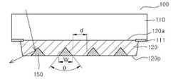
도 1은 본 발명의 하나의 구체예에 따른 디스플레이용 인터페이스패널(100)의 단면도이다. 이러한 디스플레이용 인터페이스패널(100)은 커버 윈도우(110), 제1 투명 절연성 기재(120) 및 제1 전극패턴층(150)을 포함한다. 도시된 바와 같이, 제1 투명 절연성 기재(120)는 제1면(120a)과 제2면(120b)을 가지며, 상기 제1면(120a)은 커버 윈도우(110)에 상기 제2면(120b)에는 제1 전극패턴층(150)이 형성되어 있다. 상기 제1 전극패턴층(150)의 단면은 삼각형이며, 상기 삼각형의 꼭지각(θ)이 상기 커버 윈도우(110)를 향하여 형성된다. 구체예에서, 상기 꼭지각(θ)은 30 ° 내지 150 °, 예를 들면 40 ° 내지 120 ° 일 수 있다. 상기 범위에서 패턴 시인성(visibility) 으로부터 보다 자유로울 수 있다.1 is a cross-sectional view of a
상기 제1 전극패턴층(150)이 형성된 투명 절연성 기재(120)의 제2면(120b)상에는 제2 투명 절연성 기재(130)가 더 적층될 수 있다.The second transparent insulating
도 2는 본 발명의 다른 구체예에 따른 디스플레이용 인터페이스패널의 단면도이다. 상기 제2 투명 절연성 기재는 상기 제1 투명 절연성 기재에 접하는 제1면(130a)과 이에 대향하는 제2면(130b)을 갖는다. 상기 제2면(130b)에는 제2 전극패턴층(160)이 형성될 수 있다. 상기 제2 전극패턴층(160)의 단면도 상기 제1 전극패턴층(150)과 마찬가지로 단면은 삼각형이며, 상기 삼각형의 꼭지각(θ)이 상기 커버 윈도우(110)를 향하여 형성된다. 이때 제1 전극패턴층(150)과 제2 전극패턴층(160)의 크기는 같거나 다를 수 있다.2 is a cross-sectional view of a display interface panel according to another embodiment of the present invention. The second transparent insulating base material has a first surface (130a) in contact with the first transparent insulating base material and a second surface (130b) opposed to the first surface (130a). A second
상기 커버 윈도우(110)는 디스플레이용 인터페이스패널(100)의 전면에 배치되어 디스플레이용 인터페이스패널(100)을 보호함과 동시에 광을 투과시키는 기판으로, 고투명성과 내열성을 갖는 것이 바람직하다. 상기 커버 윈도우(110)의 투명성에 관해서는 가시광선 투과율이 80% 이상인 것이 바람직하고, 내열성에 관해서는 유리전이온도가 50℃ 이상인 것이 바람직하다. 구체예에서는 상기 커버 윈도우(110)의 재료로 유리(glass), 폴리이미드계 수지, 아크릴계 수지, 폴리에스테르계 수지, 폴리카보네이트계 수지, 에폭시계 수지, 사이클로올레핀계 수지 등이 적용될 수 있다. 이러한 커버 윈도우(110)의 일면에는 제1 투명 절연성 기재(120)가 접합되는데, 그 접합 방법에 관해서는 하기의 디스플레이용 인터페이스패널의 제조방법에서 보다 상세히 설명하기로 한다. 한편, 커버 윈도우(110)의 테두리에는 디스플레이용 인터페이스패널(100)의 유효 표시 영역을 구획하는 베젤부(111)가 커버 윈도우(110)에 대한 블랙 코팅에 의해 형성될 수 있다.The
상기 제1 투명 절연성 기재(120) 및 제2 투명 절연성 기재(130)는 경화성 수지를 포함할 수 있다. 예를 들어, 제1 투명 절연성 기재(120) 및 제2 투명 절연성 기재(130)는 자외선 경화성 수지 또는 열 경화성 수지를 포함할 수 있다. 구체적으로, 제1 및 제2 투명 절연성 기재는 올레핀계 수지, 에폭시계 수지, 아크릴계 수지, 우레탄계 수지, 실리콘계 수지 등의 수지를 포함할 수 있다. 이러한 투명 절연성 기재는 몰드에 유동상의 상기 수지를 충진 및 경화시켜 형성되는데, 이에 대해서는 하기의 디스플레이용 인터페이스패널의 제조방법에서 보다 상세히 설명하기로 한다.The first transparent insulating
또한, 상기 제2 투명 절연성 기재(130)의 제2면(130b)에는 제3 투명 절연성 기재(140)가 적층 혹은 접합될 수 있다. 상기 제3 투명 절연성 기재(140)는 전극패턴이 형성되거나 전극패턴이 형성되지 않을 수 있다. 전극패턴이 형성되지 않은 상기 제3 투명 절연성 기재(140)는 오버 코트층(over coat layer)으로서의 역할을 할 수 있다.
In addition, the third transparent insulating
상기 제1 전극패턴층(150)은 제1방향을 따라 스트라이프 형태로 배열 될 수 있다. 이때, 제1 전극패턴층(150)은 제1 투명 절연성 기재(120)의 제2면(120b)에 음각 또는 양각 형태로 형성될 수 있다. 여기서, 제1 전극패턴층(150)이 양각 형태로 형성되는 경우, 그 제조 방법이 식각이나 포토리소그래피 공정 등 복잡한 공정을 수반하게 되므로, 보다 간소한 임프린팅 방법으로 간단하게 형성될 수 있도록, 제1 전극패턴층(150)은 음각 형태로 형성되는 것이 보다 바람직하다.The first
상기 제2 전극패턴층(160)은 상기 제1방향과는 다른 제2방향을 따라 스트라이프 형태로 배열될 수 있다. 상기 제2 전극패턴층(160)은 제1 전극패턴층(150)과 함께 외부로부터의 접촉에 대한 전기적 신호를 발생시키는 역할을 한다. 이때, 제1 전극패턴층(150)과 제2 전극패턴층(160) 중 어느 하나는 X축 입력 좌표를, 다른 하나는 Y축 입력 좌표를 감지하게 된다.The second
구체예에서는, 제2 전극패턴층(160)과 제1 전극패턴층(150)은 평면 상에서 서로 직교하게 형성될 수 있다. 하지만, 제1 전극패턴층(150)과 제2 전극패턴층(160)은 설계 목적에 따라 다양한 각도를 이루도록 형성될 수 있는 바, 본 발명의 실시 예에서 제1 전극패턴층(150)과 제2 전극패턴층(160)의 배치 형태를 특별히 한정하는 것은 아니다. 이와 같이 배치되는 제1 전극패턴층(150)과 제2 전극패턴층(160)은 제2 투명 절연성 기재(130)에 의해 서로 절연된 상태로 배치된다.In an embodiment, the second
상기 제2 전극패턴층(160)은 상기 제1 전극패턴층(150)과 마찬가지로, 음각 또는 양각 형태로 형성될 수 있는데, 제조 공정 간소화 및 제조 원가 절감, 디스플레이 장치의 콤팩트화 및 슬림화를 위해, 음각으로 형성되는 것이 바람직하다.Like the first
또한, 제1 전극패턴층(150)과 제2 전극패턴층(160)이 제2 투명 절연성 기재(130)에 의해 절연되는 가운데, 제1 전극패턴층(150)의 스트라이프 패턴 중 어느 하나, 예컨대, 최외각 패턴과 제2 전극패턴층(160)의 최외각 패턴은 서로 전기적으로 접속될 수 있다. 이와 같이, 전기적으로 접속되는 패턴들은 본 발명의 실시 예에 따른 디스플레이용 인터페이스패널(100)이 터치 패널로 사용될 경우 베젤부(111)에 의해 가려지는 부분의 패턴이 되고, 이러한 패턴은 디스플레이용 인터페이스패널(100)의 금속 배선으로 사용되어 FPCB와 같은 회로부에 접속되어 외부로부터의 접촉에 의해 발생된 전기적 신호를 회로부로 전송시키는 역할을 하게 된다.
While the first
구체예에서는, 제1 및 제2 전극패턴층은 단면이 삼각형인 스트라이프 패턴이 복수로 형성되고, 스트라이프 패턴의 선폭에 해당되는 상기 삼각형의 밑변(w)은 0.1 내지 20 ㎛, 예를 들면 1 내지 10 ㎛ 일 수 있다. 상기 범위에서 보다 우수한 시인성과 투과율을 갖는다. 또한 상기 삼각형의 꼭지각(θ)은 30 내지 150 ° 일 수 있다.In a specific example, the first and second electrode pattern layers are formed in a plurality of stripe patterns each having a triangular cross section, and the base w of the triangle corresponding to the line width of the stripe pattern is 0.1 to 20 탆, 10 mu m. And has better visibility and transmittance in the above range. The apex angle? Of the triangle may be 30 to 150 °.
상기 스트라이프 패턴은 동일면상에 이웃하는 다른 스트라이프 패턴과 10 내지 1500㎛의 거리(d)를 가질 수 있다. 상기 범위에서 보다 우수한 시인성과 투과율을 갖는다.
The stripe pattern may have another stripe pattern neighboring on the same plane and a distance d between 10 and 1500 mu m. And has better visibility and transmittance in the above range.
한편, 이러한 제1 및 제2 전극패턴층은 도전성 입자 및 상기 도전성 입자를 고정하는 바인더를 포함할 수 있다. 이때, 도전성 입자는 전도성 금속, 상기 금속의 합금, 전도성 고분자, 탄소입자 또는 이들의 조합 등이 사용될 수 있으며, 이에 제한되는 것은 아니다. 예를 들면, 상기 도전성 입자는 니켈, 팔라듐, 은, 구리, 금, 주석, 백금, 알루미늄, 코발트, 산화인듐, 탄소나노튜브, 그래핀, 전도성 고분자 등이 사용될 수 있으며, 이들은 단독 또는 2종 이상 조합하여 사용할 수 있다. 상기 도전성 입자는 평균입자크기(D50)가 1 nm 내지 20 ㎛, 바람직하게는 50 nm 내지 15 ㎛일 수 있다. 상기 범위에서 우수한 투과율과 시인성을 갖는다.The first and second electrode pattern layers may include conductive particles and a binder for fixing the conductive particles. The conductive particles may be conductive metals, alloys of the metals, conductive polymers, carbon particles, or combinations thereof, but are not limited thereto. For example, the conductive particles may be nickel, palladium, silver, copper, gold, tin, platinum, aluminum, cobalt, indium oxide, carbon nanotubes, graphene, conductive polymers, Can be used in combination. The conductive particles may have an average particle size (D50) of 1 nm to 20 mu m, preferably 50 nm to 15 mu m. And has excellent transmittance and visibility in the above range.
상기 바인더는 종래 ITO를 투명 전극으로 사용한 디스플레이용 인터페이스패널과 비교하여 동일 또는 그 이상의 투과율을 확보하기 위해, 제1 및 제2 투명 절연성 기재와 굴절률 정합(index matching)을 이루는 물질을 사용하는 것이 가장 바람직하고, 차선으로 제1 투명 절연성 기재(120)와 굴절률 차이가 1.72 이내 물질을 사용한다.
It is preferable to use a material having a refractive index matching with the first and second transparent insulating substrates in order to ensure the same or higher transmittance as compared with a conventional display interface panel using ITO as a transparent electrode A material having a refractive index difference of 1.72 or less with the first transparent insulating
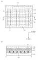
도 11 은 본 발명의 다른 구체예에 따른 디스플레이용 인터페이스패널의 평면도이다. 구체예에서는 상기 제1 전극패턴층(150) 및 상기 제2 전극패턴층(160)은 각각 메쉬구조를 가질 수 있다. 예를 들면, 상기 제1 전극패턴층(150)은 제1 방향을 따라 하나의 열에 배치되고 메쉬 구조의 복수의 라인 전극 패턴으로 이루어진 단위 셀(155)이 배열될 수 있다. 또한 상기 제2 전극패턴층(160)은 상기 제1 방향과 직교하는 제2 방향을 따라 하나의 열에 배치되고 메쉬 구조의 복수의 라인 전극 패턴으로 이루어진 단위 셀(165)이 배열될 수 있다.11 is a plan view of a display interface panel according to another embodiment of the present invention. In an exemplary embodiment, the first
한 구체예에서는 상기 단위 셀(155, 165)은 다이아몬드 형상, 삼각형 또는 사각형 등을 포함하는 다각형의 형상일 수 있다. 이들 단위셀(155, 165)들은 전기적으로 연결된다. 또한 상기 복수의 라인 전극 패턴 각각은 단면이 삼각형이며, 상기 삼각형의 꼭지각이 커버 윈도우를 향하여 형성되도록 한다.In one embodiment, the
상기 제1 투명전극패턴 및 제2 투명전극패턴은 서로 직교하는 형상으로 배치될 수 있다.
The first transparent electrode pattern and the second transparent electrode pattern may be arranged to be orthogonal to each other.
디스플레이용 인터페이스패널의 제조방법Manufacturing method of interface panel for display
이하, 본 발명의 실시 예에 따른 디스플레이용 인터페이스패널의 제조방법에 대해 설명하기로 한다.Hereinafter, a method of manufacturing a display interface panel according to an embodiment of the present invention will be described.
도 3은 본 발명의 하나의 구체예에 따른 디스플레이용 인터페이스패널의 제조방법이다. 상기 방법은, 커버 윈도우 준비단계(S1), 제1 투명 절연성 기재 적층단계(S2), 제1 전극패턴층 형성단계(S3), 제2 투명 절연성 기재 적층단계(S4), 제2 전극패턴층 형성단계(S5)를 포함할 수 있다.
3 is a method of manufacturing an interface panel for a display according to an embodiment of the present invention. The method comprises the steps of: preparing a cover window (S1), a first transparent insulating base material lamination step (S2), a first electrode pattern layer forming step (S3), a second transparent insulating base material lamination step (S4) (S5). ≪ / RTI >
먼저, 커버 윈도우 준비단계(S1)는 디스플레이용 인터페이스패널(100)의 전면에 배치되어 디스플레이용 인터페이스패널(100)을 보호함과 동시에 광을 투과시키는 커버 윈도우(110)를 준비하는 단계이다. 여기서, 이 단계(S1)에서는 고투명성과 내열성을 갖는 커버 윈도우(110)를 준비하는 것이 바람직하다. 그리고 가시광선 투과율이 80% 이상, 유리전이온도가 50℃ 이상인 커버 윈도우(110)를 준비하는 것이 바람직하다.
First, the cover window preparing step S1 is a step of preparing a
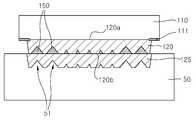
다음으로, 도 4 및 도 5를 참조하면, 제1 투명 절연성 기재 형성단계(S2)는 제1 방향을 따라 서로 이격되는 복수개의 제1 트렌치(121)가 형성된 제1 투명 절연성 기재(120)를 커버 윈도우(110)의 일 면에 적층하는 단계이다. 이 단계(S2)에서는, 바닥면에 요철 패턴(51)이 형성되어 있는 몰드(50)의 상부를 상기 커버 윈도우(110)로 덮은 후 경화성 수지로 이루어진 수지물(125)을 충진한다. 이때, 몰드(50)의 요철 패턴(51)은 공지의 리소그래피 방법이나 금속 가공을 통해 다양한 형태로 형성할 수 있다. 이와 같이 충진된 수지물(125)는 경화과정을 통해 경화할 수 있다. 상기 경화는 열경화 또는 자외선 경화를 통해 수행할 수 있다. 이와 같이, 수지물(125)을 경화시킨 후 상기 몰드를 경화된 수지물로부터 이탈시키면, 도 5에 도시된 바와 같이 복수개의 제1 트렌치가 형성된 제1 투명 절연성 기재(120)를 형성할 수 있다. 상기 제1 트렌치(121)는 단면이 삼각형이고, 상기 삼각형의 꼭지각이 상기 커버 윈도우를 향하여 형성된 것을 특징으로 한다. 이러한 제1 트렌치(121)는 제1 전극패턴층(150)을 이루는 도전성 페이스트의 충진 공간을 제공한다. 그리고 제1 트렌치(121)는 제1 전극패턴층(150)의 형상을 제어하는 역할을 하게 된다. 본 발명의 실시 예에 따른 제1 전극패턴층(150)은 스트라이프 패턴으로 형성되므로, 제1 트렌치(121)를 스트라이프 패턴으로 형성하여야 하고, 이러한 제1 트렌치(121)의 형상은 몰드(50)의 요철 패턴(51)에 의해 결정된다. 이때, 베젤부(111)에 배치되는 금속 배선을 형성하는 요철 패턴(51)의 선폭이나 선간 거리도 손쉽게 조절할 수 있는데, 이를 통해, 유효 표시 영역을 종래 보다 확장시킬 수 있다.
4 and 5, the first transparent insulating substrate forming step S2 includes forming a first transparent insulating
다음으로, 도 6을 참조하면, 제1 전극패턴층 형성단계(S3)는 복수개의 제1 트렌치(121) 내부에 도전성 페이스트를 충진시켜 제1 투명 절연성 기재(120)의 제2면(120b)에 제1 전극패턴층(150)을 형성하는 단계이다. 이 단계(S3)에서는, 먼저, 도전성 입자와 바인더를 포함하는 도전성 페이스트를 도전성 페이스트로 준비한다. 그 다음, 도시한 바와 같이, 복수개의 제1 트렌치(121) 내부에 준비한 도전성 페이스트를 채워 넣는다. 일 예로, 닥터 블레이드를 이용하여 제1 트렌치(121)가 형성된 제1 투명 절연성 기재(120)의 제2면(120b)에 도전성 페이스트를 도포한 후 제1 트렌치(121) 이외의 제1 투명 절연성 기재(120)의 제2면(120b)에 도포된 도전성 페이스트를 긁어 내거나 별도의 수단으로 제거하면, 제1 트렌치(121) 내부에만 도전성 페이스트를 채워 넣을 수 있다. 이와 같은 방법을 통해서는 제1 트렌치(121) 내부에 채워진 도전성 페이스트의 표면을 동시에 평탄화시킬 수 있다는 장점이 있다. 그리고 다른 예로, 노즐과 같은 주입 수단을 사용하여 처음부터 제1 트렌치(121)의 내부에만 도전성 페이스트를 채워 넣을 수도 있다. 그 다음, 상기 도전성 페이스트를 경화시키면, 제1 투명 절연성 기재(120)의 제2면(120b)에 스트라이프 패턴의 삼각형 단면을 가진 제1 전극패턴층(150)이 형성된다.
Referring to FIG. 6, the first electrode pattern layer forming step S3 includes filling a plurality of
다음으로, 도 7 및 도 8을 참조하면, 제2 투명 절연성 기재 적층단계(S4)는 제2 방향을 따라 서로 이격되는 복수개의 제2 트렌치(131)가 형성된 제2 투명 절연성 기재(130)를 제1 투명 절연성 기재(120)의 제2면(120b)에 적층하는 단계이다. 이 단계(S4)에서는, 바닥면에 요철 패턴(51)이 형성되어 있는 몰드(50)의 상부를 상기 제1 투명 절연성 기재(120)의 제1 전극패턴층(150)이 형성된 제2면(120b)으로 덮은 후, 경화성 수지로 이루어진 수지물(125)을 충진한다. 이때, 수지물(125)은 제1 투명 절연성 기재(120) 형성 시 사용한 수지물(125)과 동일할 수 있다. 그리고 몰드(50)의 요철 패턴(51)은 공지의 리소그래피 방법 등 실리콘 웨이퍼 가공, 기계적 가공을 통해 다양한 형태로 형성할 수 있는데, 이 단계(S4)에서 사용되는 몰드(50)는 제1 투명 절연성 기재 적층단계(S2)에서 사용된 몰드(50)와 동일하거나 다를 수 있다. 이와 같이, 수지물(125)을 경화시킨 후, 상기 몰드(50)를 경화된 수지물로부터 이탈시키면, 도 8에 도시한 바와 같이, 제2 투명 절연성 기재(130)의 하면에 제2 트렌치(131)가 형성된다.
Next, referring to FIGS. 7 and 8, the second transparent insulating base material stacking step S4 includes a second transparent insulating
다음으로, 도 9를 참조하면, 제2 전극패턴층(160) 형성단계(S5)는 복수개의 제2 트렌치(131) 내부에 도전성 페이스트를 충진시켜 제2 투명 절연성 기재(130)에 제2 전극패턴층(160)을 형성하는 단계이다. 이 단계(S5)는 제1 전극패턴층 형성단계(S3)와 동일한 공정으로 진행된다. 이 경우, 제2 투명 절연성 기재(130)의 하면에 제1 전극패턴층(150)의 스트라이프 패턴과 직교하거나 교차하는 스트라이프 패턴의 제2 전극패턴층(160)이 형성된다.
Referring to FIG. 9, the second
본 발명의 디스플레이용 인터페이스패널은 상기 방법 이외에도 다양한 방법으로 제조될 수 있다. 예를 들면 전극 패턴을 패드 인쇄법, 인프린드법, 도금법, 오프셋 인쇄법, 스크린 인쇄법, 포토리소그라피, 딥팬 나노리소그라피, 옵셋리소그라피, 레터프레스, 잉크젯 인쇄법, 그라비아 인쇄법 및 플렉소그리피법 등을 적용하여 형성할 수도 있다. 또한 제1 또는 제2 트렌치의 형성을 물리적 또는 화학적 에칭에 의해 형성할 수도 있다.
The interface panel for a display of the present invention may be manufactured by various methods other than the above method. For example, the electrode patterns may be formed by a method such as pad printing, imprinting, plating, offset printing, screen printing, photolithography, dip fan nanolithography, May be applied. The formation of the first or second trench may also be formed by physical or chemical etching.
도 12 내지 도 14는 본 발명의 다른 구체예에 따른 디스플레이용 인터페이스패널의 제조 방법을 개략적으로 나타내는 단면도이다.12 to 14 are sectional views schematically showing a method of manufacturing an interface panel for a display according to another embodiment of the present invention.
도 12의 (a) 및 (b)를 참조하면, 기판(310) 상에 제1 방향으로 배열되는 제1 전극 패턴층(150)이 형성되고, 이 때 상기 제1 전극 패턴층은 단면이 삼각형이고, 상기 삼각형의 꼭지각이 커버 윈도우를 향하여 형성되도록 한다.12A and 12B, a first
상기 제1 전극 패턴층(150) 상에 제1 투명 절연성 기재(120)가 형성된다.A first transparent insulating
한 구체예에서 상기 제1 전극 패턴층(150)은 스트라이프 형태의 패턴을 가지며, 기판(310)의 제1 방향을 따라 서로 평행하게 배열되는 적어도 하나 이상의 도전층 패턴(151)을 포함하여 이루어질 수 있다.In one embodiment, the first
상기 도전층 패턴(151)은 라인 형태를 가질 수 있으나, 반드시 이에 한정되지는 않고, 기판(310)의 제1 방향을 따라 배열되는 조건을 만족하는 한 다양한 형태를 가질 수 있다. 일 구체예에 있어서, 복수의 도전층 패턴(151)은 소정의 개수가 서로 전기적으로 묶여서 채널(152)과 연결될 수 있다. 채널(152)은 도전층 패턴(151)과 함께 다양한 인쇄법에 의해서 형성될 수 있다. 일 구체예에 있어서, 채널(152)은 디스플레이용 인터페이스패널의 배선 영역으로 연장될 수 있다. 다른 구체예에 있어서, 채널(152)은 배선 영역에서 배선 전극층으로 기능할 수 있다.The
다른 구체예에서는 상기 제1 전극 패턴층(150)은 도 11에 도시된 바와 같이 메쉬구조를 가질 수 있다. 예를 들면, 상기 제1 전극패턴층(150)은 제1 방향을 따라 하나의 열에 배치되고 메쉬 구조의 복수의 라인 전극 패턴으로 이루어진 단위 셀(155)이 배열될 수 있다. 이들 단위 셀(155)은 다이아몬드 형상, 삼각형 또는 사각형 등을 포함하는 다각형의 형상일 수 있다. 이들 단위셀(155, 165)들은 전기적으로 연결되며, 상기 복수의 라인 전극 패턴 각각은 단면이 삼각형이며, 상기 삼각형의 꼭지각이 커버 윈도우를 향하여 형성되도록 한다.In another embodiment, the first
상기 제1 투명 절연성 기재(120)은 제1 전극 패턴층(150)을 구성하는 바인더와 실질적으로 동일한 투광 특성을 가질 수 있다.The first transparent insulating
도 13의 (a) 및 (b)를 참조하면, 제1 투명 절연성 기재(120) 상에 상기 제1 방향과는 다른 제2 방향을 따라 배열되는 스트라이프 형태의 제2 전극 패턴층(160)을 형성한다. 도시된 바와 같이, 상기 제2 방향은 상기 제1 방향과 수직 방향일 수 있다.13A and 13B, a stripe-shaped second
또한, 도시된 바와 같이, 제2 전극 패턴층(160)은 스트라이프 형태의 패턴을 가지며, 단면이 삼각형이고, 상기 삼각형의 꼭지각이 커버 윈도우를 향하여 형성되도록 한다.Also, as shown in the figure, the second
상기 제2 전극 패턴층(160)은 제2 방향을 따라 서로 평행하게 배열되는 적어도 하나 이상의 도전층 패턴(161)을 포함하여 이루어질 수 있다. 도전층 패턴(161)은 라인 형태를 가질 수 있으나, 반드시 이에 한정되지는 않고, 기판(310)의 제2 방향을 따라 배열되는 조건을 만족하는 한 다양한 형태를 가질 수 있다. 일 구체예에 있어서, 복수의 도전층 패턴(161)은 소정의 개수가 서로 전기적으로 묶여서 채널(162)과 연결될 수 있다. 채널(162)은 도전층 패턴(161)과 함께 패드 인쇄법에 의해서 형성될 수 있다. 일 구체예에 있어서, 채널(162)은 디스플레이용 인터페이스패널의 배선 영역으로 연장될 수 있다. 다른 구체예에 있어서, 채널(162)은 배선 영역에서 배선 전극층으로 기능할 수 있다.The second
다른 구체예에서는 상기 제2 전극 패턴층(160)은 도 11에 도시된 바와 같이 메쉬구조를 가질 수 있다. 예를 들면, 상기 제2 전극 패턴층(160)은 제2 방향을 따라 하나의 열에 배치되고 메쉬 구조의 복수의 라인 전극 패턴으로 이루어진 단위 셀(165)이 배열될 수 있다. 이들 단위 셀(165)은 다이아몬드 형상, 삼각형 또는 사각형 등을 포함하는 다각형의 형상일 수 있다. 이들 단위셀(165)들은 전기적으로 연결되며, 상기 복수의 라인 전극 패턴 각각은 단면이 삼각형이며, 상기 삼각형의 꼭지각이 커버 윈도우를 향하여 형성되도록 한다.In another embodiment, the second
상기 제2 전극 패턴층(160)의 채널(162)과 제1 전극 패턴층(150)의 채널(152)은 사용자의 터치에 따라 발생되는 정전 커플링 신호를 외부의 칩으로 전달할 수 있으며, 상기 외부의 칩은 연산 알고리즘에 따라 사용자 터치 위치를 계산할 수 있다.The
도 14의 (a) 및 (b)를 참조하면, 제2 전극 패턴층(160) 상에 제2 투명 절연성 기재를 형성한다. 상기 제2 투명 절연성 기재(130)은 제2 전극 패턴층(160)을 구성하는 바인더와 실질적으로 동일한 투광 특성을 가질 수 있다. 따라서, 제2 투명 절연성 기재(130)을 통과하는 빛은 제2 전도층 패턴(160)과의 경계면에서 반사가 억제될 수 있다.14 (a) and 14 (b), a second transparent insulating base material is formed on the second
상기 제2 투명 절연성 기재(130)은 커버 윈도우와 접할 수 있다.
The second transparent insulating
본 발명의 단면이 삼각형인 전극패턴을 갖는 디스플레이용 인터페이스패널은 우수한 시인성을 갖는다. 즉, 도 10에 도시된 단면이 사각형인 전극패턴은 반사에 의해 패턴이 시인되는 반면, 본 발명과 같이 커버 윈도우 방향으로 꼭지각이 향하여 형성된 삼각형 단면의 전극패턴은 도 1에 도시된 바와 같이 빛의 산란에 의해 패턴 시인성을 개선시킬 수 있다.An interface panel for a display having an electrode pattern having a triangular cross section according to the present invention has excellent visibility. That is, in the electrode pattern having a rectangular cross section shown in FIG. 10, the pattern is viewed by reflection, whereas the electrode pattern of the triangular cross section formed with the vertex angle toward the cover window direction as in the present invention, The pattern visibility can be improved by scattering.
본 발명의 디스플레이용 인터페이스패널은 예컨대, 디스플레이의 전면에 부착되어 사용자의 터치 입력을 수신하는 터치스크린 패널일 수 있다.
The interface panel for a display of the present invention may be, for example, a touch screen panel attached to a front surface of a display to receive a user's touch input.
이상과 같이 본 발명은 비록 한정된 실시 예와 도면에 의해 설명되었으나, 본 발명은 상기의 실시 예에 한정되는 것은 아니며, 본 발명이 속하는 분야에서 통상의 지식을 가진 자라면 이러한 기재로부터 다양한 수정 및 변형이 가능하다.While the invention has been shown and described with reference to certain preferred embodiments thereof, it will be understood by those of ordinary skill in the art that various changes in form and details may be made therein without departing from the spirit and scope of the invention as defined by the appended claims. This is possible.
그러므로 본 발명의 범위는 설명된 실시 예에 국한되어 정해져서는 아니 되며, 후술하는 특허청구범위뿐만 아니라 특허청구범위와 균등한 것들에 의해 정해져야 한다.
Therefore, the scope of the present invention should not be limited by the described embodiments, but should be determined by the scope of the appended claims as well as the appended claims.
100: 디스플레이용 인터페이스패널 110: 커버 윈도우
111: 베젤부 120: 제1 투명 절연성 기재
121: 제1 트렌치 125: 수지물
130: 제2 투명 절연성 기재 131: 제2 트렌치
150: 제1 전극패턴층 160: 제2 전극패턴층
50: 몰드 51: 요철 패턴100: Interface panel for display 110: Cover window
111: Bezel part 120: First transparent insulating substrate
121: first trench 125: resin
130: second transparent insulating substrate 131: second trench
150: first electrode pattern layer 160: second electrode pattern layer
50: mold 51: concave / convex pattern
Claims (20)
Translated fromKorean상기 커버 윈도우에 접하는 제1면과 이에 대향하는 제2면을 갖는 제1 투명 절연성 기재; 및
상기 제1 투명 절연성 기재의 제2면에 형성된 제1 전극패턴층;
을 포함하고,
상기 제1 전극패턴층의 단면은 삼각형이며, 상기 삼각형의 꼭지각이 상기 커버 윈도우를 향하여 형성되고,
상기 제1 전극패턴층은 도전성 입자 및 상기 도전성 입자를 고정하는 바인더를 포함하는 것을 특징으로 하는 디스플레이용 인터페이스패널.
Cover window;
A first transparent insulating substrate having a first surface in contact with the cover window and a second surface opposite to the first surface; And
A first electrode pattern layer formed on a second surface of the first transparent insulating substrate;
/ RTI >
Wherein a cross section of the first electrode pattern layer is triangular and an apex angle of the triangle is formed toward the cover window,
Wherein the first electrode pattern layer comprises conductive particles and a binder for fixing the conductive particles.
상기 제1 투명 절연성 기재 상에는 제2 투명 절연성 기재가 더 적층되고;
상기 제2 투명 절연성 기재는 상기 제1 투명 절연성 기재에 접하는 제1면과 이에 대향하는 제2면을 가지고,
상기 제2 투명 절연성 기재의 제2면에는 제2 전극패턴층이 형성되고;
상기 제2 전극패턴층의 단면은 삼각형이며, 상기 삼각형의 꼭지각이 상기 커버 윈도우를 향하여 형성된 것을 특징으로 하는 디스플레이용 인터페이스패널.
The method according to claim 1,
A second transparent insulating substrate is further laminated on the first transparent insulating substrate;
Wherein the second transparent insulating base material has a first surface in contact with the first transparent insulating base material and a second surface opposite to the first surface,
A second electrode pattern layer is formed on a second surface of the second transparent insulating base material;
Wherein a cross section of the second electrode pattern layer is triangular and an apex angle of the triangle is formed toward the cover window.
상기 제1 전극패턴층은 제1방향을 따라 스트라이프 형태로 배열되며,
상기 제2 전극패턴층은 상기 제1방향과는 다른 제2방향을 따라 스트라이프 형태로 배열되고,
상기 제1 및 제2 전극패턴층은 각각 단면이 삼각형인 스트라이프 패턴이 복수로 형성되고,
상기 삼각형의 밑변(w)은 0.1 내지 20 ㎛이고, 꼭지각이 30 내지 150° 인 디스플레이용 인터페이스패널.
3. The method of claim 2,
Wherein the first electrode pattern layer is arranged in a stripe shape along a first direction,
Wherein the second electrode pattern layer is arranged in a stripe shape along a second direction different from the first direction,
Wherein the first electrode pattern layer and the second electrode pattern layer have a plurality of stripe patterns each having a triangular cross section,
Wherein the base w of the triangle is 0.1 to 20 占 퐉 and the vertex angle is 30 to 150 占.
전극패턴은 패드 인쇄법, 인프린드법, 도금법, 오프셋 인쇄법, 스크린 인쇄법, 포토리소그라피, 딥팬 나노리소그라피, 옵셋리소그라피, 레터프레스, 잉크젯 인쇄법, 그라비아 인쇄법 및 플렉소그리피법로 이루어진 군으로부터 선택된 인쇄법에 의해 형성된 디스플레이용 인터페이스패널.
The method of claim 3, wherein
The electrode patterns can be formed from the group consisting of pad printing, imprinting, plating, offset printing, screen printing, photolithography, deep-dip nanolithography, A display interface panel formed by a selected printing method.
상기 스트라이프 패턴은 동일면상에 이웃하는 다른 스트라이프 패턴과 10 내지 1500 ㎛의 거리(d)를 갖는 디스플레이용 인터페이스패널.
The method of claim 3,
Wherein the stripe pattern has another stripe pattern neighboring on the same plane and a distance d between 10 and 1500 [mu] m.
상기 제1 전극패턴층의 스트라이프 패턴 중 어느 하나와 상기 제2 전극패턴층의 스트라이프 패턴 중 어느 하나는 전기적으로 접속되는 디스플레이용 인터페이스패널.
The method of claim 3,
Wherein one of the stripe patterns of the first electrode pattern layer and the stripe pattern of the second electrode pattern layer is electrically connected.
상기 제2 전극패턴층은 도전성 입자 및 상기 도전성 입자를 고정하는 바인더를 포함하는 디스플레이용 인터페이스패널.
3. The method of claim 2,
Wherein the second electrode pattern layer comprises conductive particles and a binder for fixing the conductive particles.
상기 도전성 입자는 전도성 금속, 상기 금속의 합금, 전도성 고분자, 탄소입자 또는 이들의 조합을 포함하는 디스플레이용 인터페이스패널.
8. The method of claim 7,
Wherein the conductive particles comprise a conductive metal, an alloy of the metal, a conductive polymer, carbon particles, or combinations thereof.
상기 도전성 입자는 평균입자크기(D50)가 1 nm 내지 20 ㎛ 인 디스플레이용 인터페이스패널.
8. The method of claim 7,
Wherein the conductive particles have an average particle size (D50) of 1 nm to 20 占 퐉.
상기 바인더는 상기 제1 및 제2 투명 절연성 기재와 굴절률 차이가 1.72 이내인 디스플레이용 인터페이스패널.
8. The method of claim 7,
Wherein the binder has a refractive index difference of 1.72 or less with respect to the first and second transparent insulating base materials.
상기 제1 투명 절연성 기재 및 제2 투명 절연성 기재는 경화성 수지를 포함하는 디스플레이용 인터페이스패널.
3. The method of claim 2,
Wherein the first transparent insulating base material and the second transparent insulating base material comprise a curable resin.
상기 커버 윈도우의 테두리에는 유효 표시 영역을 구획하는 베젤부가 형성되어 있는 디스플레이용 인터페이스패널.
The method according to claim 1,
And a bezel portion for partitioning an effective display region is formed at a rim of the cover window.
(b) 상기 커버 윈도우 상에 제1 방향을 따라 서로 이격되는 복수개의 제1 트렌치가 형성된 제1 투명 절연성 기재를 형성하는 단계;
(c) 상기 복수개의 제1 트렌치 내부에 도전성 페이스트를 충진시켜 상기 제1 투명 절연성 기재에 제1 전극패턴층을 형성하는 단계;
를 포함하며,
상기 제1 트렌치는 단면이 삼각형이고, 상기 삼각형의 꼭지각이 상기 커버 윈도우를 향하여 형성되고
상기 제1 전극패턴층은 도전성 입자 및 상기 도전성 입자를 고정하는 바인더를 포함하는 것을 특징으로 하는 디스플레이용 인터페이스패널의 제조방법.
(a) preparing a cover window;
(b) forming a first transparent insulating substrate on the cover window, the first transparent insulating substrate having a plurality of first trenches spaced apart from each other along a first direction;
(c) filling the plurality of first trenches with a conductive paste to form a first electrode pattern layer on the first transparent insulating substrate;
/ RTI >
Wherein the first trench is triangular in cross section and the apex angle of the triangle is formed toward the cover window
Wherein the first electrode pattern layer includes conductive particles and a binder for fixing the conductive particles.
(d) 상기 제1 투명 절연성 기재 상에 제2 방향을 따라 서로 이격되는 복수개의 제2 트렌치가 형성된 제2 투명 절연성 기재를 적층하는 단계; 및
(e) 상기 복수개의 제2 트렌치 내부에 상기 도전성 페이스트를 충진시켜 상기 제2 투명 절연성 기재에 제2 전극패턴층을 형성하는 단계;
를 더 포함하며,
상기 제2 트렌치는 단면이 삼각형이고, 상기 삼각형의 꼭지각이 상기 커버 윈도우를 향하여 형성된 것을 특징으로 하는 디스플레이용 인터페이스패널의 제조방법.
14. The method of claim 13,
(d) depositing a second transparent insulating base material on the first transparent insulating base material, the second transparent insulating base material having a plurality of second trenches spaced apart from each other along a second direction; And
(e) filling the conductive paste in the plurality of second trenches to form a second electrode pattern layer on the second transparent insulating substrate;
Further comprising:
Wherein the second trench is triangular in cross section and the apex angle of the triangle is formed toward the cover window.
바닥면에 요철 패턴이 형성되어 있는 몰드의 상부를 상기 커버 윈도우로 덮은 후 경화성 수지를 포함하는 수지물을 충진하는 과정,
상기 수지물을 경화시키는 과정, 및
상기 몰드를 경화된 수지물로부터 이탈시키는 과정,
을 포함하는 디스플레이용 인터페이스패널의 제조방법.
14. The method of claim 13, wherein step (b)
Covering the upper part of the mold having the concavo-convex pattern formed on the bottom surface with the cover window, filling the resin material including the curable resin,
A step of curing the resin material, and
Releasing the mold from the cured resin material,
And a step of forming the display panel.
상기 (c) 단계 및 상기 (e) 단계는 각각,
상기 복수개의 제1 트렌치 또는 상기 복수개의 제2 트렌치 내부에 도전성 입자와 바인더를 포함하는 도전성 페이스트를 채워 넣는 과정, 및
상기 도전성 페이스트를 경화시키는 과정,
을 포함하는 디스플레이용 인터페이스패널의 제조방법.
15. The method of claim 14,
The step (c) and the step (e)
Filling the plurality of first trenches or the plurality of second trenches with a conductive paste containing conductive particles and a binder; and
A step of curing the conductive paste,
And a step of forming the display panel.
상기 (d) 단계는,
바닥면에 요철 패턴이 형성되어 있는 몰드의 상부를 상기 제1 투명 절연성 기재의 제1 전극패턴층이 형성된 면으로 덮은 후 경화성 수지를 포함하는 수지물을 충진하는 과정,
상기 수지물을 경화시키는 과정, 및
상기 몰드를 경화된 수지물로부터 이탈시키는 과정,
을 포함하는 디스플레이용 인터페이스패널의 제조방법.
17. The method of claim 16,
The step (d)
A step of covering an upper portion of a mold having a concave-convex pattern on a bottom surface thereof with a surface of the first transparent insulating base material on which the first electrode pattern layer is formed, and then filling a resin material containing a curable resin;
A step of curing the resin material, and
Releasing the mold from the cured resin material,
And a step of forming the display panel.
상기 요철 패턴은 리소그래피 또는 금속 가공을 통해 형성되는 디스플레이용 인터페이스패널의 제조방법.
18. A method according to any one of claims 15 to 17,
Wherein the concave-convex pattern is formed through lithography or metal working.
상기 기판의 일 방향을 따라 배열되는 스트라이프(stripe) 형태의 제1 전극 패턴층을 형성하는 단계; 및
상기 제1 전극 패턴층 상에 투명 절연성 기재로 이루어진 제1수지층을 형성하는 단계를 포함하고,
상기 제1 전극 패턴층은 단면이 삼각형이고, 상기 삼각형의 꼭지각이 커버 윈도우를 향하여 형성되며,
상기 제1 전극패턴층은 도전성 입자 및 상기 도전성 입자를 고정하는 바인더를 포함하는 것을 특징으로 하는 디스플레이용 인터페이스패널의 제조방법.
Preparing a substrate;
Forming a first electrode pattern layer in a stripe shape arranged along one direction of the substrate; And
And forming a first resin layer made of a transparent insulating base material on the first electrode pattern layer,
Wherein the first electrode pattern layer is triangular in cross section and the apex angle of the triangle is formed toward the cover window,
Wherein the first electrode pattern layer includes conductive particles and a binder for fixing the conductive particles.
상기 제2 전극 패턴층 상에 투명 절연성 기재로 이루어진 제2 수지층을 형성하는 단계를 더 포함하고,
상기 제2 전극 패턴층은 단면이 삼각형이고, 상기 삼각형의 꼭지각이 커버 윈도우를 향하여 형성된 것을 특징으로 하는 디스플레이용 인터페이스패널의 제조방법.
The method of claim 19, further comprising: forming a stripe-shaped second electrode pattern layer on the first resin layer in a second direction different from the first direction; And
Forming a second resin layer made of a transparent insulating base material on the second electrode pattern layer,
Wherein the second electrode pattern layer is triangular in cross section and the apex angle of the triangle is formed toward the cover window.
Priority Applications (2)
| Application Number | Priority Date | Filing Date | Title |
|---|---|---|---|
| KR1020120082021AKR101400700B1 (en) | 2012-07-26 | 2012-07-26 | Interface panel for display and method of fabricating thereof |
| PCT/KR2012/006491WO2014017691A1 (en) | 2012-07-26 | 2012-08-16 | Interface panel for display and method for manufacturing same |
Applications Claiming Priority (1)
| Application Number | Priority Date | Filing Date | Title |
|---|---|---|---|
| KR1020120082021AKR101400700B1 (en) | 2012-07-26 | 2012-07-26 | Interface panel for display and method of fabricating thereof |
Publications (2)
| Publication Number | Publication Date |
|---|---|
| KR20140014872A KR20140014872A (en) | 2014-02-06 |
| KR101400700B1true KR101400700B1 (en) | 2014-05-28 |
Family
ID=49997489
Family Applications (1)
| Application Number | Title | Priority Date | Filing Date |
|---|---|---|---|
| KR1020120082021AExpired - Fee RelatedKR101400700B1 (en) | 2012-07-26 | 2012-07-26 | Interface panel for display and method of fabricating thereof |
Country Status (2)
| Country | Link |
|---|---|
| KR (1) | KR101400700B1 (en) |
| WO (1) | WO2014017691A1 (en) |
Families Citing this family (4)
| Publication number | Priority date | Publication date | Assignee | Title |
|---|---|---|---|---|
| KR101642002B1 (en)* | 2015-02-23 | 2016-07-25 | (주)뉴옵틱스 | Touch Panel Sensor Sheet |
| JP2019121311A (en)* | 2018-01-11 | 2019-07-22 | シャープ株式会社 | Substrate, display device and method for producing substrate |
| KR102724101B1 (en)* | 2019-06-12 | 2024-10-31 | 엘지디스플레이 주식회사 | Display Device |
| CN113631002B (en)* | 2021-09-13 | 2022-12-13 | Oppo广东移动通信有限公司 | Shell assembly and electronic equipment |
Citations (3)
| Publication number | Priority date | Publication date | Assignee | Title |
|---|---|---|---|---|
| KR20100084260A (en)* | 2009-01-16 | 2010-07-26 | 삼성모바일디스플레이주식회사 | Window combined touch screen panel |
| KR20120014302A (en)* | 2010-08-09 | 2012-02-17 | 미래나노텍(주) | Capacitive touch panel and its manufacturing method |
| KR20120018059A (en)* | 2010-08-20 | 2012-02-29 | 미래나노텍(주) | Substrate for touch screen panel, touch screen panel and manufacturing method thereof |
Family Cites Families (2)
| Publication number | Priority date | Publication date | Assignee | Title |
|---|---|---|---|---|
| KR20100084252A (en)* | 2009-01-16 | 2010-07-26 | 삼성모바일디스플레이주식회사 | Touch screen panel |
| KR101373047B1 (en)* | 2010-09-07 | 2014-03-11 | 삼성디스플레이 주식회사 | Flexible Printed Circuit Board and Touch Screen Panel Device Having the Same |
- 2012
- 2012-07-26KRKR1020120082021Apatent/KR101400700B1/ennot_activeExpired - Fee Related
- 2012-08-16WOPCT/KR2012/006491patent/WO2014017691A1/enactiveApplication Filing
Patent Citations (3)
| Publication number | Priority date | Publication date | Assignee | Title |
|---|---|---|---|---|
| KR20100084260A (en)* | 2009-01-16 | 2010-07-26 | 삼성모바일디스플레이주식회사 | Window combined touch screen panel |
| KR20120014302A (en)* | 2010-08-09 | 2012-02-17 | 미래나노텍(주) | Capacitive touch panel and its manufacturing method |
| KR20120018059A (en)* | 2010-08-20 | 2012-02-29 | 미래나노텍(주) | Substrate for touch screen panel, touch screen panel and manufacturing method thereof |
Also Published As
| Publication number | Publication date |
|---|---|
| WO2014017691A1 (en) | 2014-01-30 |
| KR20140014872A (en) | 2014-02-06 |
Similar Documents
| Publication | Publication Date | Title |
|---|---|---|
| US10768766B2 (en) | Touch window having a sensing electrode with a variable width of a conductive line | |
| JP3192251U (en) | Touch panel and touch display device | |
| JP5075270B2 (en) | Transparent conductive element, method for manufacturing the same, input device, and electronic device | |
| CN105765501B (en) | Conductive sheet, capacitive touch panel and display device | |
| EP2827231B1 (en) | Touch window and display including the same | |
| US8947399B2 (en) | Dual-substrate capacitive touch panel | |
| US10884548B2 (en) | Touch window and display with the same | |
| KR20130138487A (en) | Touch screen having mesh patterned electrodes | |
| JP2018195341A (en) | Structure with conductor layer, touch panel, and method of manufacturing structure with conductor layer | |
| KR101400700B1 (en) | Interface panel for display and method of fabricating thereof | |
| CN104461111A (en) | Touch panel | |
| JP2014179063A (en) | Touch panel | |
| KR20140041138A (en) | Electrode member and method for manufacturing electrode member | |
| US9442613B2 (en) | Touch window | |
| KR101974158B1 (en) | Conducting substrate, touch panel comprising the same and display device comprising the same | |
| KR101391307B1 (en) | Method of preparing interface panel for display | |
| TWM478869U (en) | Touch panel | |
| CN103246401B (en) | sensing element structure of touch panel and manufacturing method thereof | |
| KR101395182B1 (en) | Interface panel for display and method of fabricating thereof | |
| KR101391306B1 (en) | Method of fabricating touch screen panel by printing method and touch screen panel manufactured by the same | |
| KR101395183B1 (en) | Interface panel for display and method of fabricating thereof | |
| KR101424657B1 (en) | Directly patterned touch panel on window lens | |
| KR101997657B1 (en) | Conducting substrate, touch panel comprising the same and display device comprising the same | |
| KR102085876B1 (en) | Electrode member and touch panel with the same | |
| KR20170075556A (en) | Conducting substrate, touch panel comprising the same and display device comprising the same |
Legal Events
| Date | Code | Title | Description |
|---|---|---|---|
| A201 | Request for examination | ||
| PA0109 | Patent application | St.27 status event code:A-0-1-A10-A12-nap-PA0109 | |
| PA0201 | Request for examination | St.27 status event code:A-1-2-D10-D11-exm-PA0201 | |
| E902 | Notification of reason for refusal | ||
| PE0902 | Notice of grounds for rejection | St.27 status event code:A-1-2-D10-D21-exm-PE0902 | |
| T11-X000 | Administrative time limit extension requested | St.27 status event code:U-3-3-T10-T11-oth-X000 | |
| P11-X000 | Amendment of application requested | St.27 status event code:A-2-2-P10-P11-nap-X000 | |
| P13-X000 | Application amended | St.27 status event code:A-2-2-P10-P13-nap-X000 | |
| PG1501 | Laying open of application | St.27 status event code:A-1-1-Q10-Q12-nap-PG1501 | |
| E701 | Decision to grant or registration of patent right | ||
| PE0701 | Decision of registration | St.27 status event code:A-1-2-D10-D22-exm-PE0701 | |
| GRNT | Written decision to grant | ||
| PR0701 | Registration of establishment | St.27 status event code:A-2-4-F10-F11-exm-PR0701 | |
| PR1002 | Payment of registration fee | St.27 status event code:A-2-2-U10-U11-oth-PR1002 Fee payment year number:1 | |
| PG1601 | Publication of registration | St.27 status event code:A-4-4-Q10-Q13-nap-PG1601 | |
| FPAY | Annual fee payment | Payment date:20170420 Year of fee payment:4 | |
| PR1001 | Payment of annual fee | St.27 status event code:A-4-4-U10-U11-oth-PR1001 Fee payment year number:4 | |
| FPAY | Annual fee payment | Payment date:20180426 Year of fee payment:5 | |
| PR1001 | Payment of annual fee | St.27 status event code:A-4-4-U10-U11-oth-PR1001 Fee payment year number:5 | |
| FPAY | Annual fee payment | Payment date:20190906 Year of fee payment:6 | |
| PR1001 | Payment of annual fee | St.27 status event code:A-4-4-U10-U11-oth-PR1001 Fee payment year number:6 | |
| PR1001 | Payment of annual fee | St.27 status event code:A-4-4-U10-U11-oth-PR1001 Fee payment year number:7 | |
| PR1001 | Payment of annual fee | St.27 status event code:A-4-4-U10-U11-oth-PR1001 Fee payment year number:8 | |
| PR1001 | Payment of annual fee | St.27 status event code:A-4-4-U10-U11-oth-PR1001 Fee payment year number:9 | |
| PC1903 | Unpaid annual fee | St.27 status event code:A-4-4-U10-U13-oth-PC1903 Not in force date:20230523 Payment event data comment text:Termination Category : DEFAULT_OF_REGISTRATION_FEE | |
| PC1903 | Unpaid annual fee | St.27 status event code:N-4-6-H10-H13-oth-PC1903 Ip right cessation event data comment text:Termination Category : DEFAULT_OF_REGISTRATION_FEE Not in force date:20230523 |