KR101397624B1 - Method for controlling power transmission in wireless power transmission apparatus and wireless power transmission apparatus thereof - Google Patents
Method for controlling power transmission in wireless power transmission apparatus and wireless power transmission apparatus thereofDownload PDFInfo
- Publication number
- KR101397624B1 KR101397624B1KR1020110026056AKR20110026056AKR101397624B1KR 101397624 B1KR101397624 B1KR 101397624B1KR 1020110026056 AKR1020110026056 AKR 1020110026056AKR 20110026056 AKR20110026056 AKR 20110026056AKR 101397624 B1KR101397624 B1KR 101397624B1
- Authority
- KR
- South Korea
- Prior art keywords
- wireless power
- power transmission
- transmission
- wireless
- charging
- Prior art date
- Legal status (The legal status is an assumption and is not a legal conclusion. Google has not performed a legal analysis and makes no representation as to the accuracy of the status listed.)
- Active
Links
- 230000005540biological transmissionEffects0.000titleclaimsabstractdescription158
- 238000000034methodMethods0.000titleclaimsabstractdescription30
- 238000001514detection methodMethods0.000claimsabstractdescription40
- 239000000126substanceSubstances0.000claimsabstractdescription5
- 238000009529body temperature measurementMethods0.000claimsdescription6
- 230000020169heat generationEffects0.000claimsdescription6
- 238000010438heat treatmentMethods0.000claimsdescription6
- 238000010586diagramMethods0.000description4
- 238000012545processingMethods0.000description4
- 230000002708enhancing effectEffects0.000description3
- 230000005674electromagnetic inductionEffects0.000description2
- 230000005855radiationEffects0.000description2
- 230000000903blocking effectEffects0.000description1
- 238000007599dischargingMethods0.000description1
- 230000001939inductive effectEffects0.000description1
- 230000000977initiatory effectEffects0.000description1
- 238000010295mobile communicationMethods0.000description1
- 238000013021overheatingMethods0.000description1
- 230000002265preventionEffects0.000description1
- 230000035945sensitivityEffects0.000description1
- 238000001228spectrumMethods0.000description1
Images

Classifications
- H—ELECTRICITY
- H02—GENERATION; CONVERSION OR DISTRIBUTION OF ELECTRIC POWER
- H02J—CIRCUIT ARRANGEMENTS OR SYSTEMS FOR SUPPLYING OR DISTRIBUTING ELECTRIC POWER; SYSTEMS FOR STORING ELECTRIC ENERGY
- H02J50/00—Circuit arrangements or systems for wireless supply or distribution of electric power
- H02J50/60—Circuit arrangements or systems for wireless supply or distribution of electric power responsive to the presence of foreign objects, e.g. detection of living beings
- H—ELECTRICITY
- H02—GENERATION; CONVERSION OR DISTRIBUTION OF ELECTRIC POWER
- H02J—CIRCUIT ARRANGEMENTS OR SYSTEMS FOR SUPPLYING OR DISTRIBUTING ELECTRIC POWER; SYSTEMS FOR STORING ELECTRIC ENERGY
- H02J50/00—Circuit arrangements or systems for wireless supply or distribution of electric power
- H02J50/10—Circuit arrangements or systems for wireless supply or distribution of electric power using inductive coupling
- H02J50/12—Circuit arrangements or systems for wireless supply or distribution of electric power using inductive coupling of the resonant type
- H—ELECTRICITY
- H02—GENERATION; CONVERSION OR DISTRIBUTION OF ELECTRIC POWER
- H02J—CIRCUIT ARRANGEMENTS OR SYSTEMS FOR SUPPLYING OR DISTRIBUTING ELECTRIC POWER; SYSTEMS FOR STORING ELECTRIC ENERGY
- H02J50/00—Circuit arrangements or systems for wireless supply or distribution of electric power
- H02J50/40—Circuit arrangements or systems for wireless supply or distribution of electric power using two or more transmitting or receiving devices
- H02J50/402—Circuit arrangements or systems for wireless supply or distribution of electric power using two or more transmitting or receiving devices the two or more transmitting or the two or more receiving devices being integrated in the same unit, e.g. power mats with several coils or antennas with several sub-antennas
- H—ELECTRICITY
- H02—GENERATION; CONVERSION OR DISTRIBUTION OF ELECTRIC POWER
- H02J—CIRCUIT ARRANGEMENTS OR SYSTEMS FOR SUPPLYING OR DISTRIBUTING ELECTRIC POWER; SYSTEMS FOR STORING ELECTRIC ENERGY
- H02J50/00—Circuit arrangements or systems for wireless supply or distribution of electric power
- H02J50/80—Circuit arrangements or systems for wireless supply or distribution of electric power involving the exchange of data, concerning supply or distribution of electric power, between transmitting devices and receiving devices
- H—ELECTRICITY
- H02—GENERATION; CONVERSION OR DISTRIBUTION OF ELECTRIC POWER
- H02J—CIRCUIT ARRANGEMENTS OR SYSTEMS FOR SUPPLYING OR DISTRIBUTING ELECTRIC POWER; SYSTEMS FOR STORING ELECTRIC ENERGY
- H02J50/00—Circuit arrangements or systems for wireless supply or distribution of electric power
- H02J50/90—Circuit arrangements or systems for wireless supply or distribution of electric power involving detection or optimisation of position, e.g. alignment
- H—ELECTRICITY
- H02—GENERATION; CONVERSION OR DISTRIBUTION OF ELECTRIC POWER
- H02J—CIRCUIT ARRANGEMENTS OR SYSTEMS FOR SUPPLYING OR DISTRIBUTING ELECTRIC POWER; SYSTEMS FOR STORING ELECTRIC ENERGY
- H02J7/00—Circuit arrangements for charging or depolarising batteries or for supplying loads from batteries
- H02J7/00032—Circuit arrangements for charging or depolarising batteries or for supplying loads from batteries characterised by data exchange
- H02J7/00045—Authentication, i.e. circuits for checking compatibility between one component, e.g. a battery or a battery charger, and another component, e.g. a power source
- H—ELECTRICITY
- H02—GENERATION; CONVERSION OR DISTRIBUTION OF ELECTRIC POWER
- H02J—CIRCUIT ARRANGEMENTS OR SYSTEMS FOR SUPPLYING OR DISTRIBUTING ELECTRIC POWER; SYSTEMS FOR STORING ELECTRIC ENERGY
- H02J7/00—Circuit arrangements for charging or depolarising batteries or for supplying loads from batteries
- H02J7/0029—Circuit arrangements for charging or depolarising batteries or for supplying loads from batteries with safety or protection devices or circuits
- H02J7/00309—Overheat or overtemperature protection
- H—ELECTRICITY
- H02—GENERATION; CONVERSION OR DISTRIBUTION OF ELECTRIC POWER
- H02J—CIRCUIT ARRANGEMENTS OR SYSTEMS FOR SUPPLYING OR DISTRIBUTING ELECTRIC POWER; SYSTEMS FOR STORING ELECTRIC ENERGY
- H02J7/00—Circuit arrangements for charging or depolarising batteries or for supplying loads from batteries
- H02J7/0029—Circuit arrangements for charging or depolarising batteries or for supplying loads from batteries with safety or protection devices or circuits
- H02J7/00304—Overcurrent protection
- H—ELECTRICITY
- H02—GENERATION; CONVERSION OR DISTRIBUTION OF ELECTRIC POWER
- H02J—CIRCUIT ARRANGEMENTS OR SYSTEMS FOR SUPPLYING OR DISTRIBUTING ELECTRIC POWER; SYSTEMS FOR STORING ELECTRIC ENERGY
- H02J7/00—Circuit arrangements for charging or depolarising batteries or for supplying loads from batteries
- H02J7/0029—Circuit arrangements for charging or depolarising batteries or for supplying loads from batteries with safety or protection devices or circuits
- H02J7/00308—Overvoltage protection
Landscapes
- Engineering & Computer Science (AREA)
- Power Engineering (AREA)
- Computer Networks & Wireless Communication (AREA)
- Charge And Discharge Circuits For Batteries Or The Like (AREA)
Abstract
Translated fromKoreanDescription
Translated fromKorean본 발명은, 무선 전력 효율을 높이기 위한, 무선 전력 전송 장치에서의 전력 전송 제어 방법 및 전력 전송 장치에 관한 것이다.
The present invention relates to a power transmission control method and a power transmission apparatus in a wireless power transmission apparatus for enhancing wireless power efficiency.
일반적으로 배터리팩(Battery pack)은 외부의 충전기로부터 전력(전기에너지)을 공급받아 충전한 상태에서 휴대용 단말기(핸드폰, PDA 등)의 작동을 위한 전원을 공급하기 위한 것으로, 전기에너지를 충전하는 배터리셀과 상기 배터리셀의 충전 및 방전(휴대용 단말기로 전기에너지를 공급)을 위한 회로 등이 구성되어 있다.2. Description of the Related Art Generally, a battery pack is a battery pack for supplying electric power for operating a portable terminal (a mobile phone, a PDA or the like) in a state of being supplied with electric power (electric energy) from an external charger, And a circuit for charging and discharging the battery cell (supplying electric energy to the portable terminal).
이러한 휴대용 단말기에 사용되는 배터리팩에 전기에너지를 충전시키기 위한 충전기와 배터리팩의 전기적 연결방식에는 상용전원을 공급받아 배터리팩에 대응하는 전압 및 전류로 변환하여 해당 배터리팩의 단자를 통해 배터리팩으로 전기에너지를 공급하는 단자공급방식이 있다.In a method of electrically connecting a charger and a battery pack to charge a battery pack used in such a portable terminal, a commercial power is supplied to the battery pack, and the battery pack is converted into a voltage and a current corresponding to the battery pack, There is a terminal supply method that supplies electric energy.
그러나, 이러한 단자공급방식으로 전원을 공급하면, 충전기와 배터리팩을 접촉하거나 분리할 경우, 양측의 단자(배터리팩의 단자 및 충전기의 단자)들이 서로 다른 전위차를 가지고 있어, 순간방전현상을 초래하는 문제점이 있었다.However, when power is supplied by such a terminal supply method, when the charger and the battery pack are brought into contact with or separated from each other, the terminals (the terminals of the battery pack and the terminals of the charger) of the two sides have different potential differences, There was a problem.
특히, 이러한 순간방전현상 등으로 인하여 양측의 단자들에 이물질이 쌓이게 되면 화재 등이 발생할 우려가 있었다.Particularly, when foreign substances are accumulated on the terminals on both sides due to the instantaneous discharge phenomenon, there is a possibility of fire or the like.
또한, 습기 등으로 인하여 배터리팩에 충전된 전기에너지가 배터리팩의 단자를 통해 외부로 자연방전되는 등의 문제점이 있음은 물론, 이로 인하여 배터리팩의 수명 및 성능의 저하를 초래하는 단점이 있었다.In addition, there is a problem in that electric energy charged in the battery pack due to moisture or the like is naturally discharged to the outside through the terminal of the battery pack, and the life and performance of the battery pack are deteriorated.
최근에는 상기와 같은 문제점을 해결하기 위하여, 무선전력전송방식을 이용한 무접점 방식의 충전시스템과 제어방법들이 제시되고 있다.Recently, a non-contact charging system and a control method using a wireless power transmission method have been proposed in order to solve the above problems.
이러한 무선 전력 전송 시스템에 있어서 안정적인 전력 수신과 더불어 무선 전력 전송 효율을 높이기 위한 노력들이 있어 왔다.
In such a wireless power transmission system, efforts have been made to increase the wireless power transmission efficiency with stable power reception.
본 발명은, 무선 전력 전송 시스템에서 이물질을 감지하여, 이에 대응되는 전력 전송 제어를 행함으로써, 무선 전력 전송 효율을 높이기 위한, 무선 전력 수신 장치에서의 전력 수신 제어 방법 및 이를 적용한 무선 전력 수신 장치를 제공하기 위한 것이다.
The present invention relates to a power reception control method in a wireless power reception apparatus and a wireless power reception apparatus using the same to increase a wireless power transmission efficiency by detecting a foreign substance in a wireless power transmission system and performing power transmission control corresponding thereto .
상술한 과제를 해결하기 위한 본 발명의 일실시예인, 무선 전력 전송 장치에서의 전력 전송 제어 방법은, 물체 감지 센서를 통해 무선 충전 중 이물질이 무선 전력 전송 장치의 충전 위치에 놓여지는지를 감지하는 단계; 상기 이물질이 물체 감지센서에 의해 감지되면, 상기 무선 전력 전송 장치의 제어부에 의해 무선 충전의 전력 손실이 계산되는 단계; 및 상기 전력 손실이 기준치 이상이면, 상기 이물질의 감지에 따라 전력 전송을 중지하는 단계를 포함할 수 있다.A method of controlling power transmission in a wireless power transmission apparatus, which is an embodiment of the present invention for solving the above-mentioned problems, includes the steps of sensing whether a foreign object is placed in a charging position of a wireless power transmission apparatus during wireless charging through an object detection sensor ; Calculating a power loss of wireless charging by a control unit of the wireless power transmission apparatus when the foreign object is detected by the object detection sensor; And stopping the power transmission according to the detection of the foreign object if the power loss is equal to or higher than the reference value.
여기서, 상기 물체 감지 센서는, 적외선 감지 센서일 수 있고, 상기 적외선 감지 센서는, 감지각이 120도 이상이고, 감지거리가 20cm 이상일 수 있다.Here, the object detection sensor may be an infrared ray sensor, and the infrared ray sensor may have a detection angle of 120 degrees or more and a detection distance of 20 cm or more.
본 발명의 일실시예의 일태양에 의하면, 상기 무선 전력 전송 장치에서의 전력 전송 제어 방법은, 상기 무선 전력 전송 장치의 1차측 코어를 통해 발신되는 펄스 신호에 대한 위상 변화 또는 전류값 변화를 측정하여 1차측 코어에 무선 전력 수신 장치가 충전 위치에 놓이는지를 감지하는 단계; 및 상기 무선 전력 수신 장치가 충전 위치에 놓이면, 무선 전력 신호를 전송하여 상기 무선 충전을 개시하는 단계를 더 포함할 수 있다.According to an aspect of the present invention, a power transmission control method in the wireless power transmission apparatus measures phase change or current value change with respect to a pulse signal transmitted through a primary side core of the wireless power transmission apparatus Sensing whether the wireless power receiving device is placed in the charging position on the primary side core; And initiating the wireless charging by transmitting a wireless power signal when the wireless power receiving device is in the charging position.
본 발명의 일실시예의 일태양에 의하면, 상기 무선 전력 전송 장치의 1차측 코어를 통해 발신되는 펄스 신호에 대한 위상 변화 또는 전류값 변화를 측정하여 1차측 코어에 무선 전력 수신 장치가 충전 위치에 놓이는지를 감지하는 단계는, 상기 1차측 코어의 제 1 전송 코일 및 제 2 전송 코일에 순차적으로 펄스신호를 전송하는 단계; 상기 제 1 전송 코일 및 제 2 전송 코일 중 하나에 발생되는 상기 펄스 신호의 위상 변화 또는 전류값 변화를 측정하는 단계; 및 상기 위상 변화 또는 전류값 변화에 기초하여, 상기 제 1 전송 코일 및 제 2 전송 코일 중 하나에 상기 무선 전력 수신 장치가 놓이는지를 감지하는 단계를 포함할 수 있다.According to an aspect of the present invention, a phase change or a change in a current value of a pulse signal transmitted through a primary side core of the wireless power transmission apparatus is measured, and a wireless power receiving apparatus is placed in a charging position Wherein the step of detecting a pulse includes sequentially transmitting a pulse signal to a first transmission coil and a second transmission coil of the primary core; Measuring a phase change or current value change of the pulse signal generated in one of the first transmission coil and the second transmission coil; And sensing whether the wireless power receiving device is located in one of the first transmission coil and the second transmission coil based on the phase change or current value change.
본 발명의 일실시예의 일태양에 의하면, 상기 무선 전력 전송 장치에서의 전력 전송 제어 방법은, 상기 무선 전력 전송 장치에서의 발열온도를 측정하는 단계; 및 상기 발열 온도가 기준 온도 이상이면, 상기 무선 충전을 중지하는 단계를 더 포함할 수 있다.
According to an aspect of the embodiment of the present invention, there is provided a method of controlling power transmission in a wireless power transmission apparatus, comprising: measuring a heating temperature in the wireless power transmission apparatus; And stopping the wireless charging if the heating temperature is higher than a reference temperature.
본 발명의 다른 실시예인, 무선 전력 전송 장치는, 무선 전력 신호 및 펄스 신호를 무선 전력 수신 장치측으로 전송하기 위해 구성된 1차측 코어; 무선 충전 중 이물질을 감지하기 위한 물체 감지 센서; 물체 감지 센서를 통해 무선 충전 중 이물질이 무선 전력 전송 장치의 충전 위치에 놓여지는지가 감지되면, 상기 무선 충전의 전력 손실을 계산하고, 상기 전력 손실이 기준치 이상이면, 상기 이물질의 감지에 따라 전력 전송을 중지하도록 상기 1차측 코어를 제어하는 전송 제어부를 포함할 수 있다.According to another embodiment of the present invention, a wireless power transmission apparatus includes a primary side core configured to transmit a wireless power signal and a pulse signal to a wireless power receiving apparatus side; An object detection sensor for detecting a foreign object during wireless charging; A power detecting unit for detecting a power loss of the wireless charging device when the foreign object is placed in the charging position of the wireless power transmission device through the object detecting sensor; And a transmission control unit for controlling the primary side core to stop the primary side core.
본 발명의 다른 실시예의 일태양에 의하면, 상기 물체 감지 센서는, 적외선 감지 센서이고, 상기 적외선 감지 센서는, 감지각이 120도 이상이고, 감지거리가 20cm 이상일 수 있다.According to another embodiment of the present invention, the object detection sensor is an infrared ray detection sensor, and the infrared ray detection sensor may have a detection angle of 120 degrees or more and a detection distance of 20 cm or more.
본 발명의 다른 실시예의 일태양에 의하면, 상기 적외선 감지센서는, 상기 무선 전력 전송 장치의 일측에 형성된 돌출부에 설치될 수 있다.According to another aspect of the present invention, the infrared sensor may be installed on a protrusion formed on one side of the wireless power transmission device.
본 발명의 다른 실시예의 일태양에 의하면, 상기 무선 전력 전송 장치는, 상기 무선 충전이 정상적으로 이루어지는지를 표시하기 위하여, 상기 돌출부에 설치된 인디케이터를 더 포함할 수 있다.According to an aspect of another embodiment of the present invention, the wireless power transmission apparatus may further include an indicator installed on the protrusion to indicate whether the wireless charging is normally performed.
본 발명의 다른 실시예의 일태양에 의하면, 상기 전송 제어부는, 상기 1차측 코어를 통해 발신되는 펄스 신호에 대한 위상 변화 또는 전류값 변화를 측정하여 1차측 코어에 무선 전력 수신 장치가 충전 위치에 놓이는지를 감지하고, 상기 무선 전력 수신 장치가 충전 위치에 놓이면, 무선 전력 신호를 전송하여 상기 무선 충전을 개시할 수 있다.According to another aspect of the present invention, the transmission control unit may measure a phase change or a current value change with respect to a pulse signal transmitted through the primary side core, And when the wireless power receiving apparatus is in the charging position, it can transmit the wireless power signal to start the wireless charging.
본 발명의 다른 실시예의 일태양에 의하면, 상기 1차측 코어는 제 1 전송 코일 및 제 2 전송 코일을 포함하고, 상기 전송 제어부는, 제 1 전송 코일 및 제 2 전송 코일에 순차적으로 펄스신호를 전송하고, 상기 제 1 전송 코일 및 제 2 전송 코일 중 하나에 발생되는 상기 펄스 신호의 위상 변화 또는 전류값 변화를 측정하며, 상기 위상 변화 또는 전류값 변화에 기초하여, 상기 제 1 전송 코일 및 제 2 전송 코일 중 하나에 상기 무선 전력 수신 장치가 놓이는지를 감지할 수 있다.According to an aspect of another embodiment of the present invention, the primary core includes a first transmission coil and a second transmission coil, and the transmission control unit sequentially transmits a pulse signal to the first transmission coil and the second transmission coil And measuring a phase change or a current value change of the pulse signal generated in one of the first transmission coil and the second transmission coil, and based on the phase change or current value change, It can be detected whether the wireless power receiving apparatus is placed in one of the transmission coils.
본 발명의 다른 실시예의 일태양에 의하면, 상기 무선 전력 전송 장치는, 상기 무선 전력 전송 장치에서의 발열온도를 측정하기 위한 온도 측정부를 더 포함하고, 상기 전송 제어부는, 상기 온도측정부에서 측정되는 상기 발열 온도가 기준 온도 이상이면, 상기 무선 충전을 중지하도록 제어할 수 있다.
According to an aspect of another embodiment of the present invention, the wireless power transmission apparatus further includes a temperature measurement section for measuring a heat generation temperature in the wireless power transmission apparatus, and the transmission control section controls the temperature measurement section And to stop the wireless charging if the heating temperature is equal to or higher than the reference temperature.
상술한 구성을 가진 본 발명의 일실시예에 따르면, 무선 충전 중 또는 무선 충전 개시 전에 무선 전력 전송 장치와 무선 전력 수신 장치 사이에 존재할 수 있는 이물질을 감지할 수 있고, 이에 따라 무선 전력 전송 제어를 함으로써 무선 전력 전송 효율을 높일 수 있다.
According to an embodiment of the present invention having the above-described configuration, it is possible to detect foreign matter that may exist between the wireless power transmission apparatus and the wireless power reception apparatus during wireless charging or before the start of wireless charging, Thereby enhancing the wireless power transmission efficiency.
도 1은 본 발명의 일실시예와 관련된 무선 전력 전송 시스템의 블록 구성도.
도 2는 본 발명의 일실시예인 무선 전력 전송 장치에서 이물질 감지를 설명하기 위한 개념도.
도 3은 본 발명의 일실시예인, 무선 전력 전송 장치에서 무선 전력 전송 제어 방법을 설명하기 위한 흐름도.1 is a block diagram of a wireless power transmission system in accordance with an embodiment of the present invention;
2 is a conceptual diagram for explaining foreign matter detection in a wireless power transmission apparatus according to an embodiment of the present invention.
3 is a flowchart illustrating a wireless power transmission control method in a wireless power transmission apparatus according to an embodiment of the present invention.
이하, 본 발명과 관련된 무선 전력 수신 장치 및 그 전력 제어 방법에 대하여 도면을 참조하여 보다 상세하게 설명한다. 이하의 설명에서 사용되는 구성요소에 대한 접미사 "모듈" 및 "부"는 명세서 작성의 용이함만이 고려되어 부여되거나 혼용되는 것으로서, 그 자체로 서로 구별되는 의미 또는 역할을 갖는 것은 아니다.Hereinafter, a wireless power receiving apparatus and a power control method thereof according to the present invention will be described in detail with reference to the drawings. The suffix "module" and " part "for the components used in the following description are given or mixed in consideration of ease of specification, and do not have their own meaning or role.
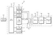
도 1은 본 발명의 일실시예인 무선 전력 전송 시스템의 블록 구성도이다. 도시된 바와 같이, 본 발명의 일실시예인 무선 전력 전송 시스템은, 무선 전력 전송 장치(100)와 무선 전력 수신 장치(200)를 포함한다. 즉, 전자기 유도 방식에 의해, 무선 전력 전송 장치(100)가 무선 전력 신호를 무선 전력 수신 장치(200)로 전송하면, 이 전력 신호를 수신한 무선 전력 수신 장치(200)는 상기 무선 전력 신호의 전력으로 배터리를 충전하거나, 무선 전력 수신 장치(200)와 연결된 전자기기에 전원을 공급하게 된다.1 is a block diagram of a wireless power transmission system according to an embodiment of the present invention. As shown in the figure, a wireless power transmission system according to an embodiment of the present invention includes a wireless
이하에서는, 무선 전력 전송 장치(100)와 무선 전력 수신 장치(200)의 구성에 대하여 각각 설명하도록 한다.Hereinafter, the configurations of the wireless
본 발명의 일시시예인 무선 전력 전송 장치(100)는, 1차측 코어(110), 전송 제어부(120) 및 AC/DC 컨버터(130)를 포함한다. 여기서 1차측 코어(110)(1차측 코일)은 전력 신호를 전자기 유도 방식으로 무선 전력 수신 장치(200)의 2차측 코어(210)에 전송하기 위한 장치로서, 본 실시예에서는 2개의 코일(즉, 제 1 전송 코일(111) 및 제 2 전송 코일(112))이 적용될 수 있다.A wireless
다시 도 1을 참조하면, 상기 1차측 코어(110)을 제어하는 전송 제어부(120)는, 객체 감지부(121), 중앙제어부(122), 스위칭제어부(123), 구동드라이버(124) 및 직렬공진형컨버터(125)를 포함할 수 있다.1, the
상기 객체 감지부(121)는 상기 1차측 코일인 1차측 코어(110)의 위상 변화 또는 전류값 변화를 감지하고, 해당 변화가 무선 전력 수신 장치(200)에 의한 것인지를 판단할 뿐만 아니라(즉 아이디 확인부로서의 기능을 가짐), 무선 전력 수신 장치(200)로부터 전송된 충전 상태 신호를 필터링하여 처리하는 기능을 수행한다. 즉, 1차측 코어(110)을 통해 전송되는 아이디 호출 신호의 응답신호인 아이디 신호가 수신되면, 이를 필터링 하여 처리하고, 충전 중, 배터리 셀이나 충전 전압에 관한 정보를 포함하는 충전 상태 신호가 수신되면. 이를 필터링하여 처리하는 기능을 한다.The
상기 중앙 제어부(122)는 상기 객체 감지부(121)의 판단결과를 전송받아 확인하고, 1차측 코어(110)에서 수신되는 아이디 신호를 분석하여, 상기 1차측 코어(110)를 통해 무선 전력 신호를 송출하기 위한 전력 신호를 상기 구동 드라이버(124)로 전송하는 역할을 한다. 또한, 후술하는 1차측 코어로부터 충전 상태신호가 수신되면, 이에 기초하여 구동 드라이버(124)를 제어하여 무선 전력 신호를 변경하는 기능을 한다.The
상기 스위칭제어부(123)는 직렬 공진형 컨버터(125)와 제 1 전송 코일(111) 및 제 2 전송 코일(112)의 사이에 스위치의 스위칭동작을 제어하는 것이다. 본 발명에서는, 2개의 전송 코일이 이용되고 있으나, 본 발명은 이에 한정되지 않고, 하나의 코일이 적용되는 경우도 포함한다. 하나의 코일이 적용되는 경우, 상기 스위칭 제어부(123)가 불필요하게 된다.The
상기 구동 드라이버(124)는 중앙 제어부(122)의 제어를 통해 직렬 공진형 컨버터(125)의 동작을 제어하는 것이다.The
상기 직렬 공진형 컨버터(125)는 구동 드라이버(124)의 제어에 의해 송출하고자 하는 전력신호를 발생하기 위한 송출전원을 생성하여 상기 1차측 코어(110)로 공급하는 것이다. 다시 말해, 중앙 제어부(122)가 요구되는 전력값을 갖는 전력 신호의 송출을 위한 전력 제어 신호를 구동 드라이버(124)로 전송하면, 상기 구동 드라이버(124)는 전송된 전력제어신호에 대응하여 직렬 공진형 컨버터(125)의 동작을 제어하고, 상기 직렬 공진형 컨버터(125)는 구동 드라이버(124)의 제어에 의하여 요구되는 전력값에 대응하는 송출전원을 1차측 코어(110)에 인가함으로써, 요구되는 세기의 무선 전력 신호가 송출되도록 하는 것이다.The
또한, 상기 직렬 공진형 컨버터(125)는 구동 드라이버(124)의 제어에 의해 제 1 전송 코일(111) 및 제 2 전송 코일(112)을 통해 각각 제 1 객체 감지 신호와 제 2 객체 감지 신호를 발생하기 위한 전원을 공급하는 역할을 한다.The
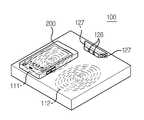
물체 감지 센서(126)는 무선 전력 전송 장치의 돌출부(도 2 참조)에 설치되어서, 무선 충전중 이물질이 무선 전력 전송 장치의 충전위치 근처에 놓여지는지를 확인하는 구성요소이다. 이러한 물체 감지 센서(126)로는 적외선 감지센서가 될 수 있다. 적외선 감지센서는 적외선을 이용해 온도, 압력, 방사선의 세기 등의 물리량이나 화학량을 검지하여 신호처리가 가능한 전기량으로 변환하여 물체를 감지하는 장치이다. 스스로 적외선을 복사하여 빛이 차단됨으로써 변화를 검지하는 능동식과, 자체에는 발광기를 가지지 않고 외계로부터 받는 적외선의 변화만을 읽어내는 수동식이 있다. 적외선이란 전자기파 스펙트럼 중 가시광선의 적색광보다 길고 마이크로파보다 짧은 파장, 즉 파장 0.75μm∼1mm의 복사선을 가리킨다. 이것을 사용함으로써 종래의 온도센서·자외선센서보다 감도·정확도가 높다. 이 적외선 감지 센서는 감지각이 120도 이상이고, 감지거리가 20cm 이상이면, 충분하다.The
인디케이터(127)는 무선 전력 전송 장치(100)의 일측에 형성된 돌출부에 형성되어, 무선 전력 전송이 잘되는지를 확인하기 위하여 구성된 것으로서, LED와 같은 발광장치로 이루어질 수 있다. 본 발명의 일실시예의 경우, 인디케이터가 2개 설치되어, 각각 제 1 전송 코일(111)과 제 2 전송 코일(112)에서 무선 전력 전송 신호가 정상적으로 발신되는지를 나타낸다.The
한편, 무선 전력 전송 장치에는 온도 회로부(온도 측정부)(도면 미포함)를 더 포함할 수 있다. 이 온도 측정부는, 무선 전력 전송 장치의 과열을 방지하기 위한 것으로, 무선 전력 전송 장치에서 발열이 이루어지는 제 1 전송 코일(111) 또는 제 2 전송 코일(112)에 의해 발열되는 무선 전력 전송 장치(100)의 주면의 온도를 측정한다.On the other hand, the wireless power transmission apparatus may further include a temperature circuit section (temperature measurement section) (not shown). The temperature measuring unit is for preventing overheating of the wireless power transmission apparatus and includes a
전송 제어부(120)의 구체적인 동작은 도 2 및 도 3를 참조하여 보다 상세하게 설명하도록 한다.The specific operation of the
AC/DC 컨버터(130)는 220V 또는 110V 의 교류 전원을 소정 전압의 직류 전원으로 변경하는 장치로서, 전술한 바와 같이, 상기 중앙 제어부(122)의 제어에 의해, 출력 전압값이 변경된다.
The AC /
그리고, 전력신호를 수신하여 전력을 공급받는 무선 전력 수신 장치(200)는, 상기 송출된 전력 신호에 의해 유도전력을 생성하는 2차측 코어(210), 유도된 전력을 정류하는 정류부(220), 정류된 전력으로 충전되는 배터리셀모듈(230), 그리고, 상기 2차측 코어(210), 정류부(220), 상기 배터리셀 모듈(230)를 제어하는 수신 제어부(240)를 포함한다. 본 발명의 무선 전력 수신 장치(200)는 배터리셀 모듈을 포함하는 패터리 팩일 수도 있고, 이 패터리 팩을 포함하는 이동 통신 단말기일 수도 있다.The wireless
2차측 코어(210)는 무선 전력 전송 장치(100)의 1차측 코어로부터 전송되는 무선 전력 신호를 수신하기 위한 구성요소이다.The
정류부(220)는 상기 2차측 코어로부터 수신되는 무선 전력을 직류 전압으로 정류하며, 충전 개시 전까지는 충전전압으로 충전 상태를 유지하게 된다.The
배터리 셀 모듈(230)은 수신 제어부(240)의 제어를 받아 상기 정류부(220)로부터의 직류 전원을 통해 충전이 되는 충전 대상이 된다. 배터리 셀 모듈 (230) 대신에 PMP, MP3, 핸드폰등의 전자기기가 될 수도 있다. 한편, 상기 배터리셀모듈(230)에는 과전압 및 과전류방지회로, 온도감지회로 등의 보호회로가 포함되어 구성되며, 또한, 배터리셀의 충전상태 등의 정보를 수집 및 처리하는 충전관리모듈이 포함된다.Under the control of the
수신 제어부(240)는 정류부(220)에서 충전된 전원의 전류를 제어하여 배터리셀모듈(230)로 적절한 전류가 흐르도록 하는 구성요소이다.
The
도 2는 본 발명의 일실시예인 무선 전력 전송 장치에서 이물질 감지를 설명하기 위한 개념도이다. 도시된 바와 같이, 본 발명의 일실시예인 무선 전력 전송 장치(100)의 주면에는 제 1 전송 코일(111)과 제 2 전송 코일(112)가 이격되어 설치된다. 그리고, 무선 전력 전송 장치(100)의 주면에는 무선 전력 수신 장치(200)가 놓여질 수 있다. 그러면, 무선 전력 수신 장치(200)가 놓여진 위치에 따라, 제 1 전송 코일(111) 또는 제 2 전송 코일(112) 중 하나를 통해 무선 전력 신호가 발신되고, 이를 수신 한 무선 전력 수신 장치(200)의 수신 제어부(240)는 배터리셀 모듈(230)을 충전하게 된다. 이 때, 상기 무선 전력 신호를 출력하는 코일에 대응하는 인디케이터(127)는 발광하게 된다.2 is a conceptual diagram for explaining foreign matter detection in a wireless power transmission apparatus according to an embodiment of the present invention. As shown in the figure, the
그런데, 무선 충전중, 동전이나 클립같은 이물질이 무선 전력 전송 장치의 주면에 위치하게 되면, 돌출부에 설치된 물체 감지 센서(126)가 상기 이물질을 감지하게 되고, 그 다음, 이에 의한 전력 손실을 계산하게 된다. 이 전력 손실이 기준값보다 크게 되면 무선 전력 신호의 전송을 중지한다. 도시된 바와 같이, 상기 물체 감지 센서(126)는 2개 설치될 수 있다. 즉, 하나는 제 1 전송 코일(111)측을 감지하도록 설치되고, 다른 하나는 제 2 전송 코일(112)측을 감지하도록 설치될 수 있다.However, when a foreign object such as a coin or a clip is placed on the main surface of the wireless power transmission device during wireless charging, the
또한, 1차측 코어(110)가 중첩되는 2개의 코일로 이루어지는 경우, 2 개의 코일은 세로방향으로 중첩설치되어, 하나의 무선 전력 수신 장치(200)에 대하여 무선 전력 신호를 전송하게 될 수 있다. 이 경우에는 하나의 물체 감지 센서(126)가 돌출부에 설치될 수 있다.Further, when the
이하에서는, 상술한 구성을 가진 무선 전력 전송 장치에서의 무선 전력 전송 제어 방법에 대하여 도 3을 참조하여 상세하게 설명하도록 한다.
Hereinafter, a radio power transmission control method in the radio power transmission apparatus having the above-described configuration will be described in detail with reference to FIG.
도 3은 본 발명의 일실시예인, 무선 전력 전송 장치에서 무선 전력 전송 제어 방법을 설명하기 위한 흐름도이다.3 is a flowchart illustrating a wireless power transmission control method in a wireless power transmission apparatus according to an embodiment of the present invention.
도시된 바와 같이, 우선, 상기 무선 전력 전송 장치(100)의 1차측 코어(110)를 통해 발신되는 펄스 신호에 대한 위상 변화 또는 전류값 변화를 측정하여 1차측 코어(110)에 무선 전력 수신 장치(200)가 충전 위치에 놓이는지를 감지한다(S11). 이 때, 도 1 및 도 2에서와 같이 2개의 코일이 1차측 코어(110)로 이용되면, 상기 1차측 코어(110)의 제 1 전송 코일(111) 및 제 2 전송 코일(112)에 순차적으로 펄스신호를 전송하고, 상기 제 1 전송 코일(111) 및 제 2 전송 코일(112) 중 하나에 발생되는 상기 펄스 신호의 위상 변화 또는 전류값 변화를 측정한 다음, 상기 위상 변화 또는 전류값 변화에 기초하여, 상기 제 1 전송 코일(111) 및 제 2 전송 코일(112) 중 하나에 상기 무선 전력 수신 장치가 놓이는지를 감지하게 된다.As shown in the figure, a phase change or current value change with respect to a pulse signal transmitted through the
한편, 이와 같이, 무선 전력 수신 장치(200)가 충전 위치에 놓여짐에 따라, 무선 전력 전송 장치(100)의 전송 제어부(120)는 1차측 코어로부터 수신되는 무선 전력 수신 장치(200)의 아이디 신호를 확인하고, 이에 따라 1차측 코어(110)를 통해 무선 전력 신호의 전송을 시작하여 무선 충전을 개시한다(S13). 그 다음, 무선 충전중 이물질이 무선 전력 전송 장치(100)의 충전 위치에 놓여지는지를 물체 감지 센서(126)를 통해 감지한다. 또는, 물체 감지 센서(126)를 통해 무선 전력 수신 장치(200)가 충전 위치에서 이탈 또는 이동되었는지를 감지한다(S15).As the wireless
이렇게, 물체 감지 센서(126)에서 이물질이 감지되면, 무선 전력 전송 장치의 전송 제어부는, 전력 손실을 측정한다(S17). 전력 손실은, 무선 전력 전송 신호 발신을 위한 전력에서 실제 충전에 사용되는 전력을 뺀 값인 절대값으로 계산될 수도 있고, 전송 효율로도 계산될 수 있다.When the
이 측정된 전력 손실이 기준값보다 크게 되면, 무선 전력 전송 장치(100)의 전송 제어부(120)는 전원 오프를 실행하여 더 이상 무선 전력 전송 신호를 발신하는 것을 방지하여 전력 낭비를 방지하게 된다.When the measured power loss is greater than the reference value, the
그 다음, 상기 측정된 전력 전력 손실이 기준값 보다 작으면, 무선 전력 전송 장치의 제어부는, 상기 무선 전력 전송 장치(100)에서의 발열온도(주면의 발열온도)를 온도 측정부를 통해 측정한다(S21). 그 다음, 상기 발열 온도가 기준 온도 이상이면, 상기 무선 충전을 중지하기 위하여 무선 전력 전송 장치(100)를 전원 오프시킨다(S23). 만약 측정되는 발열온도가 기준온도보다 낮으면, 상기 무선 전력 전송 신호를 정상적으로 전송하게 된다(S25).
Then, if the measured power loss is smaller than the reference value, the control unit of the wireless power transmission apparatus measures the heat generation temperature (main heat generation temperature) in the wireless
상술한 구성을 가진 본 발명의 일실시예에 따르면, 무선 충전 중 또는 무선 충전 개시 전에 무선 전력 전송 장치와 무선 전력 수신 장치 사이에 존재할 수 있는 이물질을 감지할 수 있고, 이에 따라 무선 전력 전송 제어를 함으로써 무선 전력 전송 효율을 높일 수 있다.
According to an embodiment of the present invention having the above-described configuration, it is possible to detect foreign matter that may exist between the wireless power transmission apparatus and the wireless power reception apparatus during wireless charging or before the start of wireless charging, Thereby enhancing the wireless power transmission efficiency.
상기와 같이 설명된 무선 전력 수신 장치 및 그 전력 제어 방법은 상기 설명된 실시예들의 구성과 방법이 한정되게 적용될 수 있는 것이 아니라, 상기 실시예들은 다양한 변형이 이루어질 수 있도록 각 실시예들의 전부 또는 일부가 선택적으로 조합되어 구성될 수도 있다.
The above-described wireless power receiving apparatus and its power control method are not limited to the configuration and method of the above-described embodiments, but the embodiments can be applied to all or some of the embodiments May be selectively combined.
100 : 무선 전력 전송 장치
111 : 제 1 전송 코일
112 : 제 2 전송 코일
120 : 전송 제어부
121 : 객체 감지부
122 : 중앙 제어부
123 : 스위칭 제어부
124 : 구동 드라이버
125 : 직렬 공진형 컨버터
126 : 물체 감지센서
127 : 인디케이터
130 : 교류/직류 컨버터
200 : 무선 전력 수신 장치
210 : 2차측 코어
220 : 정류부
230 : 배터리셀 모듈
240 : 수신 제어부100: Wireless power transmission device
111: first transmission coil
112: second transmission coil
120:
121: Object detection unit
122:
123:
124: driving driver
125: Series resonant converter
126: Object detection sensor
127: Indicator
130: AC / DC converter
200: Wireless power receiving device
210: secondary side core
220: rectification part
230: Battery cell module
240:
Claims (14)
Translated fromKorean상기 1차측 코어를 통해 수신되는 상기 무선 전력 수신 장치의 아이디 신호를 확인하는 단계;
상기 아이디 신호를 확인한 후, 무선 전력 신호를 전송하여 무선 충전을 개시하는 단계;
물체 감지 센서를 통해 무선 충전 중 이물질이 무선 전력 전송 장치의 충전 위치에 놓여지는지를 감지하는 단계;
상기 이물질이 물체 감지센서에 의해 감지되면, 상기 무선 전력 전송 장치의 제어부에 의해 무선 충전의 전력 손실이 계산되는 단계, 상기 전력 손실은, 무선 전력 전송 신호 발신을 위한 전력에서 실제 충전에 사용되는 전력을 뺀 값인 절대값 또는, 전송 효율이고,; 및
상기 전력 손실이 기준치 이상이면, 상기 이물질의 감지에 따라 전력 전송을 중지하는 단계를 포함하는, 무선 전력 전송 장치에서의 전력 전송 제어 방법.
Measuring a phase change or a current value change with respect to a pulse signal transmitted through the primary side core to detect whether the wireless power receiving apparatus is placed at the charging position in the primary side core;
Confirming an ID signal of the wireless power receiving apparatus received through the primary side core;
After confirming the ID signal, transmitting a wireless power signal to initiate wireless charging;
Sensing whether a foreign substance is placed in the charging position of the wireless power transmission device during wireless charging through the object detection sensor;
When the foreign object is detected by the object detection sensor, a power loss of the wireless charge is calculated by the control unit of the wireless power transmission apparatus, the power loss is calculated by multiplying the power used for actual charging Or an absolute value that is a transmission efficiency minus a transmission efficiency; And
And stopping the power transmission according to the detection of the foreign matter when the power loss is equal to or higher than the reference value.
상기 물체 감지 센서는, 적외선 감지 센서인, 무선 전력 전송 장치에서의 전력 전송 제어 방법.
The method according to claim 1,
Wherein the object detection sensor is an infrared ray detection sensor.
상기 적외선 감지 센서는,
감지각이 120도 이상이고, 감지거리가 20cm 이상인, 무선 전력 전송 장치에서의 전력 전송 제어 방법.
3. The method of claim 2,
The infrared sensor includes:
Wherein the sensing angle is 120 degrees or more and the sensing distance is 20 cm or more.
상기 무선 전력 전송 장치의 1차측 코어를 통해 발신되는 펄스 신호에 대한 위상 변화 또는 전류값 변화를 측정하여 1차측 코어에 무선 전력 수신 장치가 충전 위치에 놓이는지를 감지하는 단계는,
상기 1차측 코어의 제 1 전송 코일 및 제 2 전송 코일에 순차적으로 펄스신호를 전송하는 단계;
상기 제 1 전송 코일 및 제 2 전송 코일 중 하나에 발생되는 상기 펄스 신호의 위상 변화 또는 전류값 변화를 측정하는 단계; 및
상기 위상 변화 또는 전류값 변화에 기초하여, 상기 제 1 전송 코일 및 제 2 전송 코일 중 하나에 상기 무선 전력 수신 장치가 놓이는지를 감지하는 단계를 포함하는, 무선 전력 전송 장치에서의 전력 전송 제어 방법.
The method according to claim 1,
The step of measuring the phase change or current value change of the pulse signal transmitted through the primary side core of the wireless power transmission apparatus and detecting whether the wireless power reception apparatus is placed at the charging position in the primary side core,
Sequentially transmitting a pulse signal to the first transmission coil and the second transmission coil of the primary side core;
Measuring a phase change or current value change of the pulse signal generated in one of the first transmission coil and the second transmission coil; And
And sensing whether the wireless power receiving device is located in one of the first transmitting coil and the second transmitting coil based on the phase change or current value change.
상기 무선 전력 전송 장치에서의 발열온도를 측정하는 단계; 및
상기 발열 온도가 기준 온도 이상이면, 상기 무선 충전을 중지하는 단계를 포함하는, 무선 전력 전송 장치에서의 전력 전송 제어 방법.
The method according to claim 1,
Measuring a heat generation temperature in the wireless power transmission apparatus; And
And stopping the wireless charging if the heating temperature is equal to or higher than a reference temperature.
무선 충전 중 이물질을 감지하기 위한 물체 감지 센서; 및
상기 1차측 코어를 통해 발신되는 펄스 신호에 대한 위상 변화 또는 전류값 변화를 측정하여 상기 1차측 코어에 무선 전력 수신 장치가 충전 위치에 놓이는지를 감지하고, 상기 1차측 코어를 통해 수신되는 상기 무선 전력 수신 장치의 아이디 신호를 확인하고, 상기 아이디 신호를 확인한 후, 무선 전력 신호를 전송하여 상기 무선 충전을 개시한 다음, 무선 충전중 물체 감지 센서를 통해 이물질이 무선 전력 전송 장치의 충전 위치에 놓여지는지가 감지되면, 무선 전력 전송 신호 발신을 위한 전력에서 실제 충전에 사용되는 전력을 뺀 값인 절대값 또는, 전송 효율인상기 무선 충전의 전력 손실을 계산하고, 상기 전력 손실이 기준치 이상이면, 상기 이물질의 감지에 따라 전력 전송을 중지하도록 상기 1차측 코어를 제어하는 전송 제어부를 포함하는, 무선 전력 전송 장치.
A primary side core configured to transmit a wireless power signal and a pulse signal to a wireless power receiving apparatus side;
An object detection sensor for detecting a foreign object during wireless charging; And
Wherein the primary core measures a phase change or a current value change with respect to a pulse signal transmitted through the primary core to detect whether the wireless power receiving apparatus is placed at a charging position in the primary core, After confirming the ID signal of the receiving apparatus, confirming the ID signal, transmitting the wireless power signal to initiate the wireless charging, and then determining whether the foreign object is placed at the charging position of the wireless power transmission apparatus through the object sensing sensor during wireless charging An absolute value which is a value obtained by subtracting the electric power used for actual charging from the electric power for transmitting the wireless power transmission signal, And a transmission control unit for calculating the power loss of the wireless charging and controlling the primary side core to stop the power transmission according to the detection of the foreign matter if the power loss is equal to or higher than a reference value.
상기 물체 감지 센서는, 적외선 감지 센서인, 무선 전력 전송 장치.
8. The method of claim 7,
Wherein the object detection sensor is an infrared detection sensor.
상기 적외선 감지 센서는,
감지각이 120도 이상이고, 감지거리가 20cm 이상인, 무선 전력 전송 장치.
9. The method of claim 8,
The infrared sensor includes:
Wherein the sensing angle is 120 degrees or more and the sensing distance is 20 cm or more.
상기 적외선 감지센서는,
상기 무선 전력 전송 장치의 일측에 형성된 돌출부에 설치되는, 무선 전력 전송 장치.
9. The method of claim 8,
The infrared sensor includes:
And is provided on a protrusion formed on one side of the wireless power transmission device.
상기 무선 충전이 정상적으로 이루어지는지를 표시하기 위하여, 상기 돌출부에 설치된 인디케이터를 더 포함하는, 무선 전력 전송 장치.
11. The method of claim 10,
Further comprising an indicator disposed on the projection to indicate whether the wireless charging is normally performed.
상기 1차측 코어는 제 1 전송 코일 및 제 2 전송 코일을 포함하고,
상기 전송 제어부는,
제 1 전송 코일 및 제 2 전송 코일에 순차적으로 펄스신호를 전송하고, 상기 제 1 전송 코일 및 제 2 전송 코일 중 하나에 발생되는 상기 펄스 신호의 위상 변화 또는 전류값 변화를 측정하며, 상기 위상 변화 또는 전류값 변화에 기초하여, 상기 제 1 전송 코일 및 제 2 전송 코일 중 하나에 상기 무선 전력 수신 장치가 놓이는지를 감지하는, 무선 전력 전송 장치.
8. The method of claim 7,
Wherein the primary core comprises a first transmission coil and a second transmission coil,
The transmission control unit,
Sequentially transmitting a pulse signal to the first transmission coil and the second transmission coil and measuring a phase change or current value change of the pulse signal generated in one of the first transmission coil and the second transmission coil, Or based on a change in current value, whether the wireless power receiving device is placed in one of the first transmission coil and the second transmission coil.
상기 무선 전력 전송 장치에서의 발열온도를 측정하기 위한 온도 측정부를 더 포함하고,
상기 전송 제어부는,
상기 온도측정부에서 측정되는 상기 발열 온도가 기준 온도 이상이면, 상기 무선 충전을 중지하도록 제어하는, 무선 전력 전송 장치.8. The method of claim 7,
Further comprising a temperature measurement unit for measuring a heat generation temperature in the wireless power transmission apparatus,
The transmission control unit,
And stops the wireless charging when the heat generation temperature measured by the temperature measurement unit is equal to or higher than a reference temperature.
Priority Applications (6)
| Application Number | Priority Date | Filing Date | Title |
|---|---|---|---|
| KR1020110026056AKR101397624B1 (en) | 2011-03-23 | 2011-03-23 | Method for controlling power transmission in wireless power transmission apparatus and wireless power transmission apparatus thereof |
| CN201210074251.5ACN102694423B (en) | 2011-03-23 | 2012-03-20 | Method for controlling power transmission in wireless power transmission apparatus and power transmission apparatus |
| EP12160827.7AEP2503663B1 (en) | 2011-03-23 | 2012-03-22 | Method for controlling power transmission in wireless power transmission apparatus and wireless power transmission apparatus thereof |
| JP2012067866AJP5908768B2 (en) | 2011-03-23 | 2012-03-23 | Power transmission control method and wireless power transmission apparatus in wireless power transmission apparatus |
| US13/428,206US8947045B2 (en) | 2011-03-23 | 2012-03-23 | Method for controlling power transmission in wireless power transmission apparatus and wireless power transmission apparatus thereof |
| JP2016060628AJP6401730B2 (en) | 2011-03-23 | 2016-03-24 | Power transmission control method and wireless power transmission apparatus in wireless power transmission apparatus |
Applications Claiming Priority (1)
| Application Number | Priority Date | Filing Date | Title |
|---|---|---|---|
| KR1020110026056AKR101397624B1 (en) | 2011-03-23 | 2011-03-23 | Method for controlling power transmission in wireless power transmission apparatus and wireless power transmission apparatus thereof |
Related Child Applications (1)
| Application Number | Title | Priority Date | Filing Date |
|---|---|---|---|
| KR1020130040410ADivisionKR101742553B1 (en) | 2013-04-12 | 2013-04-12 | Method for controlling power transmission in wireless power transmission apparatus and wireless power transmission apparatus thereof |
Publications (2)
| Publication Number | Publication Date |
|---|---|
| KR20120108340A KR20120108340A (en) | 2012-10-05 |
| KR101397624B1true KR101397624B1 (en) | 2014-05-22 |
Family
ID=45976100
Family Applications (1)
| Application Number | Title | Priority Date | Filing Date |
|---|---|---|---|
| KR1020110026056AActiveKR101397624B1 (en) | 2011-03-23 | 2011-03-23 | Method for controlling power transmission in wireless power transmission apparatus and wireless power transmission apparatus thereof |
Country Status (5)
| Country | Link |
|---|---|
| US (1) | US8947045B2 (en) |
| EP (1) | EP2503663B1 (en) |
| JP (2) | JP5908768B2 (en) |
| KR (1) | KR101397624B1 (en) |
| CN (1) | CN102694423B (en) |
Cited By (1)
| Publication number | Priority date | Publication date | Assignee | Title |
|---|---|---|---|---|
| US12260565B2 (en) | 2021-07-29 | 2025-03-25 | Electronics And Telecommunications Research Institute | Image processing-based foreign substance detection method in wireless charging system and device performing method |
Families Citing this family (85)
| Publication number | Priority date | Publication date | Assignee | Title |
|---|---|---|---|---|
| US11397216B2 (en) | 2010-05-21 | 2022-07-26 | Qnovo Inc. | Battery adaptive charging using a battery model |
| US12081057B2 (en) | 2010-05-21 | 2024-09-03 | Qnovo Inc. | Method and circuitry to adaptively charge a battery/cell |
| US9142994B2 (en) | 2012-09-25 | 2015-09-22 | Qnovo, Inc. | Method and circuitry to adaptively charge a battery/cell |
| US11397215B2 (en) | 2010-05-21 | 2022-07-26 | Qnovo Inc. | Battery adaptive charging using battery physical phenomena |
| US10389156B2 (en) | 2010-05-21 | 2019-08-20 | Qnovo Inc. | Method and circuitry to adaptively charge a battery/cell |
| US11791647B2 (en) | 2010-05-21 | 2023-10-17 | Qnovo Inc. | Method and circuitry to adaptively charge a battery/cell |
| KR101332163B1 (en)* | 2011-09-30 | 2013-11-21 | 삼성전기주식회사 | Wireless power transfer system |
| DE202013012730U1 (en) | 2012-06-22 | 2018-12-02 | Sony Corporation | processing device |
| JP5915904B2 (en)* | 2012-06-22 | 2016-05-11 | ソニー株式会社 | Processing apparatus, processing method, and program |
| US10199835B2 (en)* | 2015-12-29 | 2019-02-05 | Energous Corporation | Radar motion detection using stepped frequency in wireless power transmission system |
| DE102012021396A1 (en)* | 2012-10-31 | 2014-04-30 | Panasonic Corp. | Non-contact electric power feeding system has indicator which notifies state of non-contact electric power supply, allowing user to know presence or absence of receiving device or existence of foreign materials through lighting of LEDs |
| JP2014103808A (en)* | 2012-11-21 | 2014-06-05 | Nec Engineering Ltd | Non-contact charge monitoring system, non-contact charging system, and non-contact charging method |
| US9362776B2 (en)* | 2012-11-27 | 2016-06-07 | Qualcomm Incorporated | Wireless charging systems and methods |
| US9431848B2 (en) | 2012-12-06 | 2016-08-30 | Samsung Electronics Co., Ltd | Method and apparatus for protecting wireless power receiver from excessive charging temperature |
| KR102143830B1 (en)* | 2012-12-06 | 2020-08-12 | 삼성전자주식회사 | Method for protecting over temperature during charging and wireless power receiver therefor |
| US9304042B2 (en)* | 2013-01-18 | 2016-04-05 | Delphi Technologies, Inc. | Foreign object detection system and method suitable for source resonator of wireless energy transfer system |
| KR102053462B1 (en)* | 2013-02-14 | 2019-12-06 | 지이 하이브리드 테크놀로지스, 엘엘씨 | Apparatus and method for detecting foreign object in wireless power transmitting system |
| WO2014129181A1 (en)* | 2013-02-19 | 2014-08-28 | パナソニック株式会社 | Foreign object detection device, foreign object detection method, and non-contact charging system |
| KR102049118B1 (en) | 2013-02-20 | 2020-01-08 | 지이 하이브리드 테크놀로지스, 엘엘씨 | Apparatus and method for detecting foreign object in wireless power transmitting system |
| US9287718B2 (en)* | 2013-03-01 | 2016-03-15 | Nokia Technologies Oy | Method, apparatus, and computer program product for foreign object detection parameter and charging data communication with wireless charging capable battery pack |
| US20140266018A1 (en)* | 2013-03-12 | 2014-09-18 | Qualcomm Incorporated | Systems and methods for extending the power capability of a wireless charger |
| KR102051682B1 (en)* | 2013-03-15 | 2019-12-03 | 지이 하이브리드 테크놀로지스, 엘엘씨 | Apparatus and method for detecting foreign object in wireless power transmitting system |
| CN103269092B (en)* | 2013-03-28 | 2016-04-13 | 小米科技有限责任公司 | A kind of employing wireless charger carries out the method for charging and wireless charger |
| US9461492B1 (en) | 2013-04-19 | 2016-10-04 | Qnovo Inc. | Method and circuitry to adaptively charge a battery/cell using a charge-time parameter |
| EP3008541A4 (en) | 2013-06-14 | 2017-02-22 | Intel Corporation | Methods and apparatus to provide power to devices |
| JP6145934B2 (en)* | 2013-07-11 | 2017-06-14 | パナソニックIpマネジメント株式会社 | Contactless power feeding device and contactless power receiving device |
| WO2015008662A1 (en)* | 2013-07-16 | 2015-01-22 | 株式会社Ihi | Foreign matter detection device and method for contactless power supply device |
| JP5622901B1 (en) | 2013-07-29 | 2014-11-12 | 日東電工株式会社 | Wireless power transmission device and method for controlling power supply of wireless power transmission device |
| CN104467054B (en) | 2013-09-24 | 2017-08-08 | 华硕电脑股份有限公司 | Protective sheath and protection suit with wireless function of charging |
| US9921045B2 (en) | 2013-10-22 | 2018-03-20 | Qualcomm Incorporated | Systems, methods, and apparatus for increased foreign object detection loop array sensitivity |
| US20150115881A1 (en)* | 2013-10-25 | 2015-04-30 | Samsung Electro-Mechanics Co., Ltd. | Wireless power transceiver and portable terminal having the same |
| DE102013223794A1 (en)* | 2013-11-21 | 2015-05-21 | Robert Bosch Gmbh | Energy transmission system and method for diagnosing a power transmission system |
| EP3086436B1 (en)* | 2013-12-16 | 2018-04-18 | Panasonic Intellectual Property Management Co., Ltd. | Contactless charging device, program therefor, and automobile having contactless charging device mounted therein |
| CN103852631A (en)* | 2014-01-11 | 2014-06-11 | 深圳市普林泰克科技有限公司 | Algorithm for indirectly detecting metal foreign bodies for wireless charger |
| US10554070B2 (en) | 2014-01-16 | 2020-02-04 | Mediatek Inc. | Method for performing wireless charging control of an electronic device with aid of simple response indicating acknowledgement, and associated apparatus |
| US9906063B2 (en) | 2014-01-16 | 2018-02-27 | Mediatek Inc. | Method for performing wireless charging control of an electronic device with aid of random phase-delay packet, and associated apparatus |
| US10447061B2 (en) | 2014-01-16 | 2019-10-15 | Mediatek Inc. | Method for performing wireless charging control of an electronic device with aid of variant slot timing and simple response indicating acknowledgement, and associated apparatus |
| US9685815B2 (en) | 2014-01-16 | 2017-06-20 | Mediatek Inc. | Method for performing wireless charging control with aid of admittance detection, and associated apparatus |
| US9941751B2 (en) | 2014-01-27 | 2018-04-10 | Mediatek Inc. | Method for performing wireless charging control of an electronic device with aid of predetermined data in non-volatile memory, and associated apparatus |
| DE102014202163A1 (en)* | 2014-02-06 | 2015-08-06 | Volkswagen Aktiengesellschaft | Method for charging an electric or hybrid vehicle, charging unit, charging station and device for preventing a fire during inductive charging of an electric or hybrid vehicle |
| US9772401B2 (en)* | 2014-03-17 | 2017-09-26 | Qualcomm Incorporated | Systems, methods, and apparatus for radar-based detection of objects in a predetermined space |
| KR20150130795A (en)* | 2014-05-14 | 2015-11-24 | 주식회사바텍 | X-ray photographing apparatus using power supply by wireless |
| US10295693B2 (en) | 2014-05-15 | 2019-05-21 | Witricity Corporation | Systems, methods, and apparatus for foreign object detection loop based on inductive thermal sensing |
| CN105226843B (en) | 2014-05-27 | 2017-09-15 | 松下知识产权经营株式会社 | Wireless power transmission system and power transmission device of wireless power transmission system |
| US10574079B1 (en)* | 2014-06-20 | 2020-02-25 | Qnovo Inc. | Wireless charging techniques and circuitry for a battery |
| CN105334539B (en)* | 2014-06-30 | 2018-09-14 | 无锡华润矽科微电子有限公司 | The method that foreign bodies detection is realized in wireless charging |
| US10454307B2 (en) | 2014-08-04 | 2019-10-22 | Jabil Inc. | Wireless power apparatus, system and method |
| JP6359924B2 (en)* | 2014-09-17 | 2018-07-18 | トヨタ自動車株式会社 | Non-contact power transmission / reception system |
| KR101675495B1 (en)* | 2014-12-15 | 2016-11-22 | 한솔테크닉스(주) | Power hub device of radio charge base |
| US10302795B2 (en) | 2014-12-30 | 2019-05-28 | Witricity Corporation | Systems, methods, and apparatus for detecting ferromagnetic foreign objects in a predetermined space |
| US10324215B2 (en) | 2014-12-30 | 2019-06-18 | Witricity Corporation | Systems, methods, and apparatus for detecting ferromagnetic foreign objects in a predetermined space |
| SE538428C2 (en)* | 2015-03-23 | 2016-06-21 | Nok9 Ab | A testing device for wireless power transfer, and an associated method |
| US20160301238A1 (en)* | 2015-04-10 | 2016-10-13 | Intel Corporation | Managing presence and long beacon extension pulses |
| US9787128B2 (en)* | 2015-07-21 | 2017-10-10 | Hon Hai Precision Industry Co., Ltd. | Wireless charger and wireless charging method |
| CN106410991B (en)* | 2015-07-30 | 2021-08-27 | 松下知识产权经营株式会社 | Foreign object detection device, wireless power transmission device, and wireless power transmission system |
| KR102241991B1 (en)* | 2015-08-13 | 2021-04-19 | 삼성전자주식회사 | Wireless charging method and apparatus thereof |
| US10128698B2 (en) | 2016-06-20 | 2018-11-13 | Hyundai America Technical Center, Inc | Device and method for detecting an object within a wireless charging region |
| WO2018008841A1 (en)* | 2016-07-06 | 2018-01-11 | 엘지이노텍(주) | Wireless power control method and apparatus for wireless charging |
| WO2018034405A1 (en)* | 2016-08-19 | 2018-02-22 | 엘지전자 주식회사 | Wireless power transmission device |
| CN106412293B (en)* | 2016-09-29 | 2020-01-10 | 宇龙计算机通信科技(深圳)有限公司 | Foreign matter detection method and device and terminal equipment |
| JP6834345B2 (en)* | 2016-10-25 | 2021-02-24 | 富士ゼロックス株式会社 | Power receiving equipment and wireless power supply system |
| CN116470663A (en)* | 2016-12-06 | 2023-07-21 | Lg伊诺特有限公司 | Method and apparatus for detecting foreign matter |
| EP3340431A1 (en)* | 2016-12-20 | 2018-06-27 | Koninklijke Philips N.V. | System for impressed current cathodic protection |
| JP6827853B2 (en)* | 2017-03-09 | 2021-02-10 | キヤノン株式会社 | Power supply device and its control method, and power supply system |
| US10530177B2 (en)* | 2017-03-09 | 2020-01-07 | Cochlear Limited | Multi-loop implant charger |
| US10581282B2 (en) | 2017-08-30 | 2020-03-03 | Nxp Usa, Inc. | Methods and systems for foreign objection detection in wireless energy transfer systems |
| WO2019117140A1 (en)* | 2017-12-11 | 2019-06-20 | パナソニックIpマネジメント株式会社 | Wireless power transmission system, power transmitting device, and power receiving device |
| EP3553917B1 (en)* | 2018-04-09 | 2021-09-01 | NXP USA, Inc. | A power transmitter unit |
| EP3553918B1 (en) | 2018-04-09 | 2020-11-25 | NXP USA, Inc. | A power transmitter unit |
| US20200235612A1 (en)* | 2019-01-23 | 2020-07-23 | Mediatek Singapore Pte. Ltd. | Addressing borderline foreign object detection results |
| US11221663B2 (en)* | 2019-02-07 | 2022-01-11 | Datalogic Ip Tech S.R.L. | Removal prediction of a data reader from a charging base unit |
| WO2021062297A1 (en)* | 2019-09-25 | 2021-04-01 | Lexin Electronics Co., Ltd | Mobile smartphone charging system |
| KR102272743B1 (en)* | 2019-11-25 | 2021-07-07 | 지이 하이브리드 테크놀로지스, 엘엘씨 | Apparatus and method for detecting foreign object in wireless power transmitting system |
| KR102178775B1 (en)* | 2019-11-29 | 2020-11-16 | 지이 하이브리드 테크놀로지스, 엘엘씨 | Apparatus and method for detecting foreign object in wireless power transmitting system |
| CN112937322B (en)* | 2019-12-10 | 2025-04-22 | 中光电智能机器人股份有限公司 | Monitoring system and power supply control method |
| CN111030268A (en)* | 2019-12-31 | 2020-04-17 | 国网山东省电力公司临沂供电公司 | A kind of control method of wireless transmission device of power grid |
| JP7566483B2 (en)* | 2020-03-31 | 2024-10-15 | キヤノン株式会社 | Power transmission device, method and program performed by the power transmission device |
| KR102119553B1 (en)* | 2020-04-17 | 2020-06-08 | (주)에프티글로벌 | Sensing system and sensing method for foreign object |
| CN114069754A (en) | 2020-08-10 | 2022-02-18 | 台达电子企业管理(上海)有限公司 | Wireless charging method and system |
| US11923697B2 (en) | 2020-11-04 | 2024-03-05 | Samsung Electronics Co., Ltd. | Wireless power transmitting apparatus and method for controlling wireless power transmitting apparatus |
| CN112910106A (en)* | 2021-01-27 | 2021-06-04 | 安徽农业大学 | Wireless charging system of express delivery scanning rifle |
| DE112022003660T5 (en)* | 2021-07-21 | 2024-05-23 | Microchip Technology Incorporated | Object detection in wireless charging systems and related systems, methods and devices |
| CN113895252A (en)* | 2021-09-24 | 2022-01-07 | 上海万暨电子科技有限公司 | Automobile wireless charging foreign matter detection system and method |
| CN115882615B (en)* | 2021-09-28 | 2025-08-29 | 华润微集成电路(无锡)有限公司 | Method, device and processor for realizing foreign object detection in wireless charging system |
| US12100972B2 (en)* | 2021-11-10 | 2024-09-24 | Renesas Electronics America Inc. | Foreign object detection based on transmitter input parameter |
Citations (4)
| Publication number | Priority date | Publication date | Assignee | Title |
|---|---|---|---|---|
| JP2007267578A (en)* | 2006-03-30 | 2007-10-11 | Mitsubishi Heavy Ind Ltd | Obstacle detector, energy supply device and system |
| JP2008017562A (en)* | 2006-07-03 | 2008-01-24 | Mitsubishi Electric Corp | Contactless charger |
| KR20090113418A (en)* | 2008-04-28 | 2009-11-02 | 정춘길 | Wireless Power Charging System |
| KR20100037022A (en)* | 2007-03-22 | 2010-04-08 | 파우워매트 엘티디. | Signal transfer system |
Family Cites Families (25)
| Publication number | Priority date | Publication date | Assignee | Title |
|---|---|---|---|---|
| JPH11168839A (en)* | 1997-12-02 | 1999-06-22 | Sanyo Electric Co Ltd | Non-contact-type charging device |
| JP2003018757A (en)* | 2001-06-29 | 2003-01-17 | Toko Inc | Contactless charging device |
| CN1309142C (en)* | 2002-07-24 | 2007-04-04 | 冉茂鑫 | Self-coupling mutual inductance uninterrupted voltage conversion method and uninterrupted switching power supply |
| GB2414120B (en)* | 2004-05-11 | 2008-04-02 | Splashpower Ltd | Controlling inductive power transfer systems |
| GB2414121B (en)* | 2004-05-11 | 2008-04-02 | Splashpower Ltd | Controlling inductive power transfer systems |
| US7208912B2 (en)* | 2004-09-24 | 2007-04-24 | Lear Corporation | Inductive battery recharging system with peak voltage detection |
| JP4155408B2 (en)* | 2005-09-29 | 2008-09-24 | ソニー・エリクソン・モバイルコミュニケーションズ株式会社 | Charging device and charging system |
| JP3979540B2 (en) | 2005-12-28 | 2007-09-19 | 株式会社コナミデジタルエンタテインメント | GAME DEVICE, GAME DEVICE CONTROL METHOD, GAME SYSTEM, GAME SYSTEM CONTROL METHOD, AND PROGRAM |
| US8491159B2 (en)* | 2006-03-28 | 2013-07-23 | Wireless Environment, Llc | Wireless emergency lighting system |
| JP5049018B2 (en)* | 2007-01-09 | 2012-10-17 | ソニーモバイルコミュニケーションズ株式会社 | Non-contact charger |
| JP4899917B2 (en)* | 2007-02-20 | 2012-03-21 | セイコーエプソン株式会社 | Power transmission control device, power transmission device, electronic device, and tan δ detection circuit |
| WO2009040998A1 (en)* | 2007-09-27 | 2009-04-02 | Panasonic Corporation | Contactless charger |
| JP4600462B2 (en)* | 2007-11-16 | 2010-12-15 | セイコーエプソン株式会社 | Power transmission control device, power transmission device, electronic device, and non-contact power transmission system |
| KR100971737B1 (en)* | 2007-11-30 | 2010-07-21 | 정춘길 | Multi contactless charging system and control method |
| WO2009069844A1 (en)* | 2007-11-30 | 2009-06-04 | Chun-Kil Jung | Multiple non-contact charging system of wireless power transmision and control method thereof |
| EP3179640A1 (en)* | 2008-09-27 | 2017-06-14 | WiTricity Corporation | Wireless energy transfer systems |
| US8446046B2 (en)* | 2008-10-03 | 2013-05-21 | Access Business Group International Llc | Power system |
| JP5258521B2 (en)* | 2008-11-14 | 2013-08-07 | トヨタ自動車株式会社 | Power supply system |
| JP5351499B2 (en)* | 2008-11-28 | 2013-11-27 | 長野日本無線株式会社 | Contactless power transmission system |
| JP2010136464A (en)* | 2008-12-02 | 2010-06-17 | Casio Computer Co Ltd | Power transmitter and power transmission method |
| DE102009033236A1 (en)* | 2009-07-14 | 2011-01-20 | Conductix-Wampfler Ag | Device for inductive transmission of electrical energy |
| CN102474133A (en)* | 2009-07-23 | 2012-05-23 | 富士通株式会社 | Power transmission device, wireless power supply system, and wireless power supply device |
| JP2011036052A (en)* | 2009-08-03 | 2011-02-17 | Sanyo Electric Co Ltd | Battery charger |
| JP5478984B2 (en)* | 2009-08-19 | 2014-04-23 | 長野日本無線株式会社 | Power transmission device and contactless power transmission system |
| US8575944B2 (en)* | 2009-11-03 | 2013-11-05 | Robert Bosch Gmbh | Foreign object detection in inductive coupled devices |
- 2011
- 2011-03-23KRKR1020110026056Apatent/KR101397624B1/enactiveActive
- 2012
- 2012-03-20CNCN201210074251.5Apatent/CN102694423B/enactiveActive
- 2012-03-22EPEP12160827.7Apatent/EP2503663B1/enactiveActive
- 2012-03-23USUS13/428,206patent/US8947045B2/enactiveActive
- 2012-03-23JPJP2012067866Apatent/JP5908768B2/enactiveActive
- 2016
- 2016-03-24JPJP2016060628Apatent/JP6401730B2/enactiveActive
Patent Citations (4)
| Publication number | Priority date | Publication date | Assignee | Title |
|---|---|---|---|---|
| JP2007267578A (en)* | 2006-03-30 | 2007-10-11 | Mitsubishi Heavy Ind Ltd | Obstacle detector, energy supply device and system |
| JP2008017562A (en)* | 2006-07-03 | 2008-01-24 | Mitsubishi Electric Corp | Contactless charger |
| KR20100037022A (en)* | 2007-03-22 | 2010-04-08 | 파우워매트 엘티디. | Signal transfer system |
| KR20090113418A (en)* | 2008-04-28 | 2009-11-02 | 정춘길 | Wireless Power Charging System |
Cited By (1)
| Publication number | Priority date | Publication date | Assignee | Title |
|---|---|---|---|---|
| US12260565B2 (en) | 2021-07-29 | 2025-03-25 | Electronics And Telecommunications Research Institute | Image processing-based foreign substance detection method in wireless charging system and device performing method |
Also Published As
| Publication number | Publication date |
|---|---|
| US8947045B2 (en) | 2015-02-03 |
| CN102694423A (en) | 2012-09-26 |
| EP2503663A1 (en) | 2012-09-26 |
| JP6401730B2 (en) | 2018-10-10 |
| EP2503663B1 (en) | 2019-01-23 |
| CN102694423B (en) | 2015-05-27 |
| JP2016136835A (en) | 2016-07-28 |
| JP2012205500A (en) | 2012-10-22 |
| KR20120108340A (en) | 2012-10-05 |
| US20120242285A1 (en) | 2012-09-27 |
| JP5908768B2 (en) | 2016-04-26 |
Similar Documents
| Publication | Publication Date | Title |
|---|---|---|
| KR101397624B1 (en) | Method for controlling power transmission in wireless power transmission apparatus and wireless power transmission apparatus thereof | |
| KR101246693B1 (en) | Wireless power receiving device and power control method thereof | |
| KR101742553B1 (en) | Method for controlling power transmission in wireless power transmission apparatus and wireless power transmission apparatus thereof | |
| CN106961147B (en) | Wireless power transmission system with overheat protection function and method | |
| KR101267076B1 (en) | Power control method and wireless power transfer assembly in wireless power transfer assembly | |
| KR102118296B1 (en) | Wireless power transmitting device and method for controlling to transmit wireless power signal in wireless power transmitting device | |
| US20120313579A1 (en) | Contactless power supply device and contactless charging system | |
| KR20150056222A (en) | Wireless power transmission device which enables to simultaneously charge | |
| KR101213089B1 (en) | Method for controlling received power in wireless power receiving device and wireless power receiving device thereof | |
| KR101046659B1 (en) | Battery Wireless Charging Device for Mobile Devices | |
| KR101261338B1 (en) | Charger non-contact and contact charger and controlling method thereof | |
| KR101254258B1 (en) | Method for controlling wireles power transmission in wireless power transmission device and wireless power transmission device using the same | |
| KR101213087B1 (en) | Method for controlling received power in wireless power receiving device and wireless power receiving device thereof | |
| KR20130048736A (en) | Non-contact power transmission syatem with overheat protection and method thereof | |
| KR20180099585A (en) | Non-contact power transmission syatem with overheat protection and method thereof |
Legal Events
| Date | Code | Title | Description |
|---|---|---|---|
| A201 | Request for examination | ||
| PA0109 | Patent application | Patent event code:PA01091R01D Comment text:Patent Application Patent event date:20110323 | |
| PA0201 | Request for examination | ||
| E902 | Notification of reason for refusal | ||
| PE0902 | Notice of grounds for rejection | Comment text:Notification of reason for refusal Patent event date:20120521 Patent event code:PE09021S01D | |
| PG1501 | Laying open of application | ||
| E90F | Notification of reason for final refusal | ||
| PE0902 | Notice of grounds for rejection | Comment text:Final Notice of Reason for Refusal Patent event date:20121227 Patent event code:PE09021S02D | |
| A107 | Divisional application of patent | ||
| PA0107 | Divisional application | Comment text:Divisional Application of Patent Patent event date:20130412 Patent event code:PA01071R01D | |
| E902 | Notification of reason for refusal | ||
| PE0902 | Notice of grounds for rejection | Comment text:Notification of reason for refusal Patent event date:20130820 Patent event code:PE09021S01D | |
| E701 | Decision to grant or registration of patent right | ||
| PE0701 | Decision of registration | Patent event code:PE07011S01D Comment text:Decision to Grant Registration Patent event date:20140220 | |
| GRNT | Written decision to grant | ||
| PR0701 | Registration of establishment | Comment text:Registration of Establishment Patent event date:20140514 Patent event code:PR07011E01D | |
| PR1002 | Payment of registration fee | Payment date:20140515 End annual number:3 Start annual number:1 | |
| PG1601 | Publication of registration | ||
| FPAY | Annual fee payment | Payment date:20180430 Year of fee payment:5 | |
| PR1001 | Payment of annual fee | Payment date:20180430 Start annual number:5 End annual number:5 | |
| FPAY | Annual fee payment | Payment date:20190430 Year of fee payment:6 | |
| PR1001 | Payment of annual fee | Payment date:20190430 Start annual number:6 End annual number:6 | |
| PR1001 | Payment of annual fee | Payment date:20200504 Start annual number:7 End annual number:7 | |
| PR1001 | Payment of annual fee | Payment date:20210426 Start annual number:8 End annual number:8 |