KR101397543B1 - One number voip bridge call control system, and method thereof - Google Patents
One number voip bridge call control system, and method thereofDownload PDFInfo
- Publication number
- KR101397543B1 KR101397543B1KR1020130060066AKR20130060066AKR101397543B1KR 101397543 B1KR101397543 B1KR 101397543B1KR 1020130060066 AKR1020130060066 AKR 1020130060066AKR 20130060066 AKR20130060066 AKR 20130060066AKR 101397543 B1KR101397543 B1KR 101397543B1
- Authority
- KR
- South Korea
- Prior art keywords
- voip
- vbd
- call
- wake
- bridge
- Prior art date
- Legal status (The legal status is an assumption and is not a legal conclusion. Google has not performed a legal analysis and makes no representation as to the accuracy of the status listed.)
- Expired - Fee Related
Links
Images


Classifications
- H—ELECTRICITY
- H04—ELECTRIC COMMUNICATION TECHNIQUE
- H04L—TRANSMISSION OF DIGITAL INFORMATION, e.g. TELEGRAPHIC COMMUNICATION
- H04L65/00—Network arrangements, protocols or services for supporting real-time applications in data packet communication
- H04L65/1066—Session management
- H—ELECTRICITY
- H04—ELECTRIC COMMUNICATION TECHNIQUE
- H04L—TRANSMISSION OF DIGITAL INFORMATION, e.g. TELEGRAPHIC COMMUNICATION
- H04L65/00—Network arrangements, protocols or services for supporting real-time applications in data packet communication
- H04L65/10—Architectures or entities
- H04L65/1045—Proxies, e.g. for session initiation protocol [SIP]
Landscapes
- Engineering & Computer Science (AREA)
- Multimedia (AREA)
- Computer Networks & Wireless Communication (AREA)
- Signal Processing (AREA)
- Business, Economics & Management (AREA)
- General Business, Economics & Management (AREA)
- Telephonic Communication Services (AREA)
Abstract
Translated fromKoreanDescription
Translated fromKorean본 발명은 원넘버 VoIP 브릿지 호 제어시스템 및 방법에 관한 것으로, 보다 구체적으로는, 단일번호를 공유하는 복수의 VoIP브릿지 단말들이 상호 폰-투-폰(Phone to Phone) 전화 걸기 및 전화 돌려주기, 그리고 데이터 전달이 가능하게 하도록 하기 위한 원넘버 VoIP 브릿지 호 제어시스템 및 방법에 관한 것이다.
The present invention relates to a system and method for controlling a one-number VoIP bridge call, and more particularly, to a system and method for controlling a one-number VoIP bridge call, in which a plurality of VoIP bridge terminals sharing a single number are used for telephone- Number VoIP bridge call control system and method for making data transmission possible.
VoIP 브릿지는 종래 유선전화의 브릿지와 유사하게 VoIP교환기에서 1개의 전화번호를 복수의 VoIP 단말기가 공유해 여러 장소에서 사용하는 방식이다.The VoIP bridge is similar to the conventional bridging of a landline telephone, in which a plurality of VoIP terminals share one telephone number in a VoIP exchange and are used in various places.
도 1는 종래의 VoIP 브릿지 동시착신 호 동작을 나타내는 흐름도이다. 도 1을 참조하면, 단계(S①)에서 VoIP브릿지 멤버인 IP폰들도 타 IP폰과 동일하게 VoIP교환기에게 등록 (REGISTER) 메시지를 송출하여 VoIP 준비상태를 만든다.FIG. 1 is a flowchart illustrating a conventional VoIP bridge simultaneous call operation. Referring to FIG. 1, in step S (1), IP phones that are VoIP bridge members transmit a REGISTER message to a VoIP exchange in the same manner as other IP phones to make a VoIP ready state.
단계(S②)에서는 주기적으로 등록 (REGISTER) 메시지를 송출하여 항상 연결 상태를 유지해야 한다.In step S (2), a REGISTER message should be periodically transmitted to maintain the connection state at all times.
단계(S③)에서 호(Call) 가 인입되면 단계(S④)에서 VoIP교환기는 해당 번호에 등록된 모든 IP폰들에게 호출(INVITE) 메시지를 송신한다.If a call is received in
이에 따라, 단계(S⑤)에서 IP폰들은 모두 Ring 호출 상태가 된다. 이후 단계(S⑥)에서 어느 IP폰이 응답하면 200K 응답신호를 전송한다. 다음으로, 단계(S⑦)에서 응답한 단말은 통화 상태가 되고, 단계(S⑧)에서 이때 VoIP교환기는 나머지 IP폰들 모두에게 CANCEL 메시지를 보내어 Ring을 취소한다.Accordingly, in step S5, all of the IP phones are put into a ring call state. When the IP phone responds in step S6, a 200K response signal is transmitted. Next, the terminal responding at the step S? Is put in a call state, and at the step S8, the VoIP exchange sends a CANCEL message to all the remaining IP phones to cancel the ring.
이러한 방식을 사용하는 종래의 방식은 많은 문제점이 있다. 첫째로, 종래 VoIP 교환기는 당초 독립된 복수 개 회선을 1개 번호로 별도의 1개 전화번호로 통합 지정함으로써 VoIP 브릿지가 가능하지만, 구성 회선 수 만큼 자원을 소모하므로 경제적으로 사용이 불합리하다.Conventional approaches using this approach have many problems. Firstly, the conventional VoIP exchanger is capable of VoIP bridge by integrating a plurality of independent lines into a single telephone number, but consuming resources as many as the number of configuration lines, which is uneconomical to use economically.
둘째로, 종래 VoIP 교환기의 VoIP 브릿지를 위하여 1개 회선 전화번호 산하에 VoIP 단말기를 여러 대 등록할 수 있게 허용하여 유선전화와 유사한 브릿지를 제공하여 모든 VoIP 단말의 동시착신이 가능하지만, 각 단말기 상호 1:1 통화 또는 돌려주기 등 종합 서비스 제공은 불가능하다.Secondly, it is possible to register multiple VoIP terminals under one line telephone number for the VoIP bridge of the conventional VoIP exchanger, so that it is possible to simultaneously receive all VoIP terminals by providing a bridge similar to that of a landline telephone. However, It is impossible to provide comprehensive services such as 1: 1 call or return.
이러한 방식에서는 3가지 구조적 한계를 갖고 있다. 제 1 구조적 한계로는 VoIP단말은 언제라도 착신을 보장하기 위하여 항상 VoIP교환기에 등록(REGISTER) 상태를 유지해야 한다. 제 2 구조적 한계로는 세계표준 VoIP 프로토콜 규약에서 동일번호를 부여받은 단말기 상호 호출하는 방법이 존재하지 않음으로써 VoIP브릿지 단말 상호 간 특정 단말을 지정 호출하는 것이 불가능하며, 제 3 구조적 한계로는 동시착신 호출음(Ring)에 대한 거절/허용 선택이 불가능하다.
There are three structural limitations in this approach. As a first structural limitation, a VoIP terminal must always maintain a REGISTER state in a VoIP exchange in order to guarantee an incoming call at any time. As a second structural limitation, there is no method for mutually calling a terminal given the same number in the standard VoIP protocol standard, so that it is impossible to designate a specific terminal between VoIP bridge terminals, and as a third structural limitation, It is not possible to select the reject / allow for ring.
[관련기술문헌][Related Technical Literature]
1. PSTN 겸용 VoIP 전화기를 이용한 VoIP P2P 통화에서 PSTN 전화번호를 이용한 발신의 VoIP 서비스용 PSTN 전화번호 데이터 베이스를 이용한 VoIP 서비스 시스템(VoIP Service system for VoIP call setup with PSTN number by using PSTN number database on VoIP service system) (특허출원번호 제10-2003-0032242호)1. A VoIP service system using a PSTN phone number database for VoIP service using a PSTN phone number in a VoIP P2P call using a PSTN combined VoIP phone (VoIP service system for VoIP call setup with PSTN number database on VoIP service system (Patent Application No. 10-2003-0032242)
2. 호 설정 프로토콜 기반의 음성패킷망 연동 서버를 포함하는 연동망 및 연동 방법(VoIP communication network including VoIP communication server based on SIP and VoIP communication method) (특허출원번호 제10-2008-0065341호)2. VoIP communication network including VoIP communication server based SIP and VoIP communication method (Patent Application No. 10-2008-0065341) including a voice packet network interworking server based on call setup protocol
본 발명은 상기의 문제점을 해결하기 위한 것으로, 단일번호를 공유하는 복수의 VoIP브릿지 단말들이 상호 폰-투-폰 전화걸기 및 전화 돌려주기, 그리고 데이터 전달이 가능하게 하도록 하기 위한 원넘버 VoIP 브릿지 호(Call) 제어시스템 및 방법을 제공하기 위한 것이다.SUMMARY OF THE INVENTION The present invention has been made to solve the above-mentioned problems, and it is an object of the present invention to provide a VoIP bridge system for a plurality of VoIP bridge terminals sharing a single number to enable mutual phone-to-phone dialing, And to provide a call control system and method.
그러나 본 발명의 목적들은 상기에 언급된 목적으로 제한되지 않으며, 언급되지 않은 또 다른 목적들은 아래의 기재로부터 당업자에게 명확하게 이해될 수 있을 것이다.
However, the objects of the present invention are not limited to the above-mentioned objects, and other objects not mentioned can be clearly understood by those skilled in the art from the following description.
상기의 목적을 달성하기 위해 본 발명의 실시예에 따른 원넘버 VoIP 브릿지 호 제어시스템은, VoIP교환기, VoIP브릿지 호 제어 장치(VBCC : VoIP Bridge Call Controller), Wake-up Push 서버, IP네트워크, L2 이더넷 스위치, Wi-Fi AP(엑세스포인트), 유선(Ethernet) VoIP 브릿지 단말기(VBD : VoIP Bridge Device), WiFi VoIP 브릿지 단말기(VBD), 이동통신 사업자, 이동통신 기지국, 이동통신 VoIP 단말기(Mobile VBD)를 포함하는 원넘버 VoIP 브릿지 호(Call) 제어시스템에 있어서, 상기 VBCC(VoIP Bridge Call Controller)는, 각 제어 블록과 DB(Data Base)로 구성하며, VoIP 단말 연동 기능을 통해 VBD(VoIP Bridge Device)들과 연동하며, VoIP 표준 프로토콜(Protocol)” 연동 및 등록(REGISTER) 대행 프록시(Proxy) 기능과 VBD 식별자 탈부착 기능을 수행하는 VoIP프로토콜 블록); Wake-up Table DB를 통하여 VBD들의 제어 요청을 수행하고 Wake-up Push 서버에게 Push 메시지 전송을 요청하는 VoIP브릿지 호제어 블록; 및 VBD와 메시지 송수신을 수행하는 VoIP단말 연동 블록; 를 포함하는 것을 특징으로 한다.In order to accomplish the above object, a call control system for a one-number VoIP bridge according to an exemplary embodiment of the present invention includes a VoIP switch, a VoIP bridge call controller (VBCC), a wake-up push server, (VoD) bridge device (VBD), a WiFi VoIP bridge terminal (VBD), a mobile communication carrier, a mobile communication base station, a mobile communication VoIP terminal (Mobile VBD The VoIP bridge call controller includes a control block and a DB, and is connected to a VoIP bridge through a VoIP terminal interworking function. (VoIP protocol block) which performs a VoIP standard protocol "interworking, REGISTER proxy function, and VBD identifier attach / detach function interlocked with the devices" A VoIP bridge call control block for requesting control of VBDs through a wake-up Table DB and requesting a push-up message to a wake-up push server; And a VoIP terminal interlocking block for performing message transmission / reception with the VBD; And a control unit.
이때, 상기 VBD는, 상기 VoIP교환기와 단절상태로 대기하다가, 호(Call) 가 발생되는 시점에서만 상기 VoIP교환기에 등록(REGISTER)되며, 이는 발신 또는 착신의 경우 모두에 해당되는 것을 특징으로 한다.At this time, the VBD is registered in the VoIP exchange only when a call is generated while the VBD is in a state of being disconnected from the VoIP exchange, and this is applicable to both the origination and the incoming call.
또한, 단일 전화번호를 공유하는 상기 VBD는 각각 고유 식별자에 의해 구별되며, 각 전화번호당 한 쌍의 Wake-up 제어 스위치, 즉 S1 및 S2를 갖는데, S1이 ON 이면 동시착신 Ring을 허용하고, S2가 ON 이면 해당 VBD를 호출 가능한 것을 특징으로 한다.In addition, the VBDs sharing a single telephone number are distinguished by their respective unique identifiers, and have a pair of Wake-up control switches, S1 and S2, for each telephone number, allowing simultaneous incoming ring if S1 is ON, When the S2 is ON, the corresponding VBD can be called.
또한, 발신 VBD에서 특정 VBD 만 S2=ON으로 설정변경요청을 상기 VBCC에게 보내어, Wake-up Table을 설정한 후 자기 번호로 전화를 걸고, 상기 VBCC는, 상기 VoIP교환기가 보내는 착신 호출(INVITE)를 수신하여 Wake-up Table DB에서 S2=ON 인 VBD에게 Wake-up Push를 송출하여 대기중인 VBD를 기동시키고, 기동된 VBD가 상기 VoIP교환기에게 등록(REGISTER) 하고, 상기 VBCC는 현재 호(Call)를 상기 VoIP교환기에게 재전달하면 상기 VoIP교환기가 등록된 VBD)에게 호출(INVITE)를 송출하여 호출이 완성되는 것을 특징으로 한다.In addition, in the calling VBD, only a specific VBD is set to S2 = ON, the setting change request is sent to the VBCC, the calling party sets a wake-up table, and then dials its own number. The VBCC transmits an incoming call (INVITE) And transmits a Wake-up Push to the VBD having S2 = ON in the Wake-up Table DB to activate the standby VBD, and registers the activated VBD to the VoIP exchange (REGISTER). The VBCC transmits the current call ) To the VoIP exchange, the call is completed by sending an INVITE to the VBD registered with the VoIP exchange.
상기의 목적을 달성하기 위해 본 발명의 제 1 실시예에 따른 원넘버 VoIP 브릿지 호 제어방법은, 원넘버 VoIP 브릿지 호(Call) 제어방법 중 VoIP브릿지 동시착신 호 세부 과정은, VoIP 교환기가 착신 INVITE를 수신하면 VBD 대신 등록(REGISTER)중인 VBCC에게 INV를 전송하는 제 1 단계; 상기 VoIP교환기가 Wake-up Table에서 S1=ON 이고 S2=ON 인 모든 VBD에게 Wake-up Push를 송출하는 제 2 단계; Wake-up Push에 의해 기동된 VBD는 상기 VoIP교환기 측으로 등록하는 제 3 단계; 상기 VBD는 KA(Active)메시지에 활성화되었음을 VBCC에게 통지하는 제 4 단계; 상기 VBCC가 KA 메시지에 의하여 302MOVE로 상기 VoIP 교환기로 현재 호에 대한 호출을 되돌리는 제 5 단계; 상기 VoIP교환기가 302MOVE에 의해 VBD로 다시 INVITE를 송신하는데, 등록된 단말에게만 전송하는 제 6 단계; INVITE를 수신한 단말은 Ring 상태가 되고, 먼저 응답하는 VBD가 200OK로 상기 VoIP교환기에게 전송하는 제 7 단계; 상기 VoIP교환기가 200OK 메시지를 발신측에게 전송하는 제 8 단계; 및 발신측과 VBD#1은 통화 상태가 된 뒤, 통화 모드가 되면 상기 VoIP교환기가 나머지 VBD에게 CANCEL 을 보내어 Ring을 취소하는 제 9 단계; 를 포함하는 것을 특징으로 한다.In order to accomplish the above object, a method for controlling a call number-based VoIP bridge call according to a first embodiment of the present invention is characterized in that the VoIP bridge simultaneous call incoming call control method among the original number VoIP bridge call control method comprises: A first step of transmitting the INV to the VBCC registering instead of the VBD; A second step in which the VoIP exchange sends a Wake-up Push to all VBDs with S1 = ON and S2 = ON in the Wake-up Table; A third step of registering the VBD activated by the Wake-up Push to the VoIP exchange side; A fourth step of notifying the VBCC that the VBD is activated in the KA (Active) message; A fifth step of the VBCC returning a call to the current call to the VoIP exchange at 302 MOVE by a KA message; A sixth step of the VoIP exchange transmitting INVITE back to VBD by 302 MOVE, to the registered terminal only; The terminal receiving the INVITE is in the Ring state, and the VBD responding first is transmitted to the VoIP exchange at 200 OK; An eighth step of the VoIP exchange transmitting a 200 OK message to a calling party; And a ninth step of the VoIP exchange to send a CANCEL to the remaining VBDs to cancel the Ring if the calling mode and the VBD # And a control unit.
상기의 목적을 달성하기 위해 본 발명의 제 2 실시예에 따른 원넘버 VoIP 브릿지 호 제어방법은, 원넘버 VoIP 브릿지 호(Call) 제어방법 중 VoIP브릿지 1:1 지정호출 호 세부 과정은, VBCC가 동일번호의 VBD를 대표하여 하나의 VBD 자격으로VoIP교환기에게 항상 등록(REGISTER) 상태를 유하는 제 1 단계; VBD#1 단말이 표시장치 화면 메뉴에서 VBD#을 지정 호출하도록 버튼을 선택하면, VBD#1은 Wake-up Table 설정요청 메시지를 VBCC에게 송출하는 제 2 단계; 상기 VBCC가 현재 Wake-up Table의 설정값을 임시 버퍼에 저장한 후, 요청에 따라 “VBD#3/S2=ON”으로 설정하고, 설정완료 응답을 돌려주는 제 3 단계; VBD#1가 상기 VoIP교환기에 등록(REGISTER) 메시지를 보내어 준비상태로 만든 뒤, 호출대상=자기번호”로 호출 메시지(INVITE)를 상기 VoIP교환기로 전송하는 제 4 단계; 상기 VoIP교환기가 호출(INVITE) 메시지를 받고 VoIP브릿지 절차에 따라 소속된 모든 VBD들에게 동일한 호출(INVITE) 메시지를 전송하는 제 5 단계; 상기 VBCC가 수신한 INVITE의 발신자가 자기번호이면 VBD 상호 통화로 판단하고, Wake-up Table에서 S2=ON 인 VBD를 찾아내는 제 6 단계; 상기 VBCC가 상기 VoIP교환기로부터 호출 메시지를 수신하면, Wake-up Table에서 S2=ON 인 VBD#3 를 찾아내어 Wake-up Push 메시지 전송을 요청하는 제 7 단계; VBD#3 이 Wake-up Push 를 수신하여 대기 상태에서 기동하고, VoIP 프로그램은 상기 VoIP교환기에게 등록(REGISTER) 메시지를 보내어 전화 준비 상태로 만드는 제 8 단계; VBD#3은 상기 VBCC에게 자신이 등록되었음을 알리면, 상기 VBCC는 자신이 수신했던 호출(INVITE)를 VoIP교환기에게 재호출(302MOVE) 메시지로 전송하고, “재호출상태” 임을 저장하는 제 9 단계; 상기 VoIP교환기가 재호출(302MOVE)에 의해 그때에 등록(REGISTER)된 모든 VoIP 단말들에게 호출(INVITE)를 전송하는 제 10 단계; 및 VBD#3은 전화 호출 Ring 이 울리게 되고, 전화를 착신할 수 있게 되며, 상기 VBCC가 호출(INVITE) 수신 후 “재호출상태” 이면 즉시 Wake-up Table 을 임시버퍼에 저장했던 값으로 환원시켜 다음 동작을 준비하고, 호출된 VBD#3은 Ring 상태가 되어 정상 호출 절차가 성공되는 제 11 단계; 를 포함하는 것을 특징으로 한다.
In order to achieve the above object, a method for controlling a call number-based VoIP bridge call according to a second embodiment of the present invention is characterized in that the VoIP bridge 1: A first step of always having a REGISTER state to the VoIP exchange in a VBD status on behalf of the VBD of the same number; When the
본 발명의 실시예에 따른 원넘버 VoIP 브릿지 호(Call) 제어시스템 및 방법은, 단일번호를 공유하는 복수의 VoIP브릿지 단말들이 상호 폰-투-폰 전화걸기 및 전화 돌려주기, 그리고 데이터 전달이 가능한 효과를 제공한다.
A system and method for controlling a call number-based VoIP bridge call according to an embodiment of the present invention is characterized in that a plurality of VoIP bridge terminals sharing a single number can perform phone-to-phone dialing, Effect.
도 1은 종래의 VoIP 브릿지 동시착신 호 동작을 나타내는 흐름도.
도 2는 본 발명의 실시예에 따른 원넘버 VoIP 브릿지 호(Call) 제어시스템을 나타내는 도면
도 3은 도 2에서의 VoIP브릿지 호 제어 장치(VBCC : VoIP Bridge Call Controller)를 나타내는 도면
도 4는 본 발명의 실시예에 따른 Wake-up Table 을 구성하는 방법을 나타내는 도면
도 5는 외부에서 착신된 호에 대한 진행 과정을 나타내는 도면
도 6은 VBD 지정호출 호에 대한 진행 과정을 나타내는 도면
도 7은 본 발명의 실시예에 따른 원넘버 VoIP 브릿지 호(Call) 제어방법 중 VoIP브릿지 동시착신 호 세부 과정을 나타내는 흐름도
도 8은 본 발명의 실시예에 따른 원넘버 VoIP 브릿지 호(Call) 제어방법 중 VoIP브릿지 1:1 지정호출 호 세부 과정을 나타내는 흐름도
도 9는 본 발명의 실시예에 따른 원넘버 VoIP 브릿지 호(Call) 제어방법 중 VoIP브릿지 돌려주기 호 세부 과정을 나타내는 흐름도
도 10은 본 발명의 실시예에 따른 원넘버 VoIP 브릿지 호(Call) 제어방법 중 VoIP브릿지 동시 착신 Ring 거절 세부 과정을 나타내는 흐름도Brief Description of the Drawings Fig. 1 is a flow diagram illustrating a conventional VoIP bridge simultaneous incoming call operation.
2 is a diagram showing a circle number VoIP bridge call control system according to an embodiment of the present invention;
3 is a diagram illustrating a VoIP bridge call controller (VBCC) in FIG.
4 is a diagram illustrating a method of configuring a wake-up table according to an embodiment of the present invention;
5 is a diagram showing the progress of an incoming call from outside;
FIG. 6 is a diagram showing the progress of the VBD designation call; FIG.
FIG. 7 is a flowchart illustrating a detail procedure of a VoIP bridge concurrently incoming call among a method of controlling a call number VoIP bridge call according to an embodiment of the present invention.
FIG. 8 is a flowchart illustrating a detail procedure of a VoIP bridge 1: 1 designation call among a method of controlling a call number-based VoIP bridge call according to an embodiment of the present invention.
FIG. 9 is a flowchart illustrating a call detail call process of a VoIP bridge among a call control method of a source number VoIP bridge according to an exemplary embodiment of the present invention.
FIG. 10 is a flowchart illustrating a VoIP bridge concurrent Incoming Ring rejection detail procedure in a method of controlling a call number-based VoIP bridge call according to an embodiment of the present invention.
이하, 본 발명의 바람직한 실시예의 상세한 설명은 첨부된 도면들을 참조하여 설명할 것이다. 하기에서 본 발명을 설명함에 있어서, 관련된 공지 기능 또는 구성에 대한 구체적인 설명이 본 발명의 요지를 불필요하게 흐릴 수 있다고 판단되는 경우에는 그 상세한 설명을 생략할 것이다.DETAILED DESCRIPTION OF THE PREFERRED EMBODIMENTS Hereinafter, a detailed description of preferred embodiments of the present invention will be given with reference to the accompanying drawings. In the following description of the present invention, detailed description of known functions and configurations incorporated herein will be omitted when it may make the subject matter of the present invention rather unclear.
본 명세서에 있어서는 어느 하나의 구성요소가 다른 구성요소로 데이터 또는 신호를 '전송'하는 경우에는 구성요소는 다른 구성요소로 직접 상기 데이터 또는 신호를 전송할 수 있고, 적어도 하나의 또 다른 구성요소를 통하여 데이터 또는 신호를 다른 구성요소로 전송할 수 있음을 의미한다.
In the present specification, when any one element 'transmits' data or signals to another element, the element can transmit the data or signal directly to the other element, and through at least one other element Data or signal can be transmitted to another component.
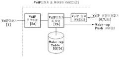
도 2는 본 발명의 실시예에 따른 원넘버 VoIP 브릿지 호(Call) 제어시스템을 나타내는 도면이다. 도 2를 참조하면, 원넘버 VoIP 브릿지 호(Call) 제어시스템은 단일번호를 공유하는 복수 VoIP 단말의 호 제어장치 및 네트워크를 구성함으로써, VoIP교환기(1), VoIP브릿지 호 제어 장치(VBCC : VoIP Bridge Call Controller)(2), Wake-up Push 서버(3), IP네트워크(4), L2 이더넷 스위치(5), Wi-Fi AP(엑세스포인트)(6), 유선(Ethernet) VoIP 브릿지 단말기(VBD : VoIP Bridge Device)(7), WiFi VoIP 브릿지 단말기(VBD)(8), 이동통신 사업자(9), 이동통신 기지국(10), 이동통신 VoIP 단말기(Mobile VBD)(11)를 포함한다.FIG. 2 is a diagram illustrating a circle number VoIP bridge call control system according to an embodiment of the present invention. 2, a call control system for a one-number VoIP bridge includes a
그리고, 도 3는 도 2에서의 VoIP브릿지 호 제어 장치(VBCC : VoIP Bridge Call Controller)(2)를 나타내는 도면이다. 도 3을 참조하면, VBCC(VoIP Bridge Call Controller)(2)는 도 3과 같이, 각 제어 블록과 DB(Data Base)로 구성하며, VoIP 단말 연동 기능을 통해 VBD(VoIP Bridge Device)(7,8,11,...)들과 연동한다.FIG. 3 is a diagram showing a VoIP bridge call controller (VBCC) 2 in FIG. 3, a VBCC (VoIP Bridge Call Controller) 2 includes a control block and a DB (Data Base) as shown in FIG. 3, and a VoIP Bridge Device (VBD) 7, 8, 11, ...).
한편, 도 3에서 VoIP프로토콜 블록(2a)은“VoIP 표준 프로토콜(Protocol)” 연동 및 등록(REGISTER) 대행 프록시(Proxy) 기능과 VBD 식별자 탈부착 기능을 수행한다. 그리고 도 3에서의 VoIP브릿지 호제어 블록(2b)은 Wake-up Table DB를 통하여 VBD(7,8,11,..)의 제어 요청을 수행하고 Wake-up Push 서버에게 Push 메시지 전송을 요청한다. VoIP단말 연동 블록(2c)은 VBD(7,8,11,..)와 메시지 송수신을 수행한다.3, the
VBD(7,8,11,..)는 VoIP교환기(1)와 단절상태로 대기하다가, 호(Call) 가 발생되는 시점에서만 VoIP교환기(1)에 등록(REGISTER) 된다. 이는 발신 또는 착신의 경우 모두에 해당 된다.The VBDs 7, 8, 11, .. are in a state of being disconnected from the
한편, 핵심 요소인 Wake-up Table 을 구성하는 방법은 도 4와 같다.On the other hand, a method of constructing a key element, a Wake-up Table, is shown in FIG.
즉, 단일 전화번호를 공유하는 VBD(VoIP Bridge Device)(7,8,11,..)는 각각 고유 식별자에 의해 구별되며, 도 4와 같이 각 전화번호당 한 쌍의 Wake-up 제어 스위치, 즉 S1 및 S2를 갖는데, S1이 ON 이면 동시착신 Ring을 허용하고, S2가 ON 이면 해당 VBD를 호출 가능한 것으로 정의한다. CS는 csn(Call State Number)를 기록해 관리하는 보조 수단이다. 식별자 구성 사례로써, 종래의 전화번호 끝에 “#NN” 식별자를 추가하는 것이 가능하다. VBCC(2)와 VBD(7,8,11,..)는 이 식별자를 상호 인식하지만, 종래의 VoIP교환기(1)는 인식이 불가능하므로, VoIP교환기(1)에게는 식별자를 제거하고 종래의 번호 체계로 상호 교환한다.
That is, the VBD (VoIP Bridge Device) (7,8,11, ..) sharing a single telephone number is distinguished by a unique identifier, and as shown in FIG. 4, a pair of a wake- That is, when S1 is ON, simultaneous incoming ring is allowed, and when S2 is ON, the VBD is defined as callable. CS is an auxiliary means for recording and managing csn (Call State Number). As an example of the configuration of an identifier, it is possible to add an identifier "#NN" to the end of a conventional telephone number. The
착신 호(Call)는 외부 인입 호(Call)와 VBD 지정호출인 경우로 구분된다.An incoming call is divided into an external incoming call and a VBD designated call.
먼저, 도 5는 외부에서 착신된 호에 대한 진행 과정을 나타내는 도면이다. 도 5를 참조하면, 첫째, 해당 전화번호의 Wake-up 테이블 DB를 꺼내어 S1 스위치가ON이고 S2 스위치가 ON인 VBD에게만 Wake-up Push 신호를 송출하여 대기중인 VBD(7,8,11,..)를 기동시킨 후(제 1 단계), 둘째, 해당 VBD(7,8,11,..)가 응답하여 VoIP교환기(1)에게 등록(REGISTER) 한 후 준비되었음을 VBCC(2)에게 통보해 주면(제 2 단계), 셋째, VBCC(2)는 현재 호(Call)를 VoIP에게 재전달하면 VoIP교환기(1)가 등록된 VBD에게 호출(INVITE)를 송출하여 호출을 완성한다(제 3 단계).
First, FIG. 5 is a diagram illustrating the progress of an incoming call from outside. Referring to FIG. 5, first, a wake-up table DB of the corresponding telephone number is taken out, and a Wake-up Push signal is sent only to the VBD whose S1 switch is ON and the S2 switch is ON, and the
다음으로, 도 6은 VBD 지정호출 호에 대한 진행 과정을 나타내는 도면이다.Next, FIG. 6 is a diagram showing the progress of the call to the VBD designation call.
첫째, 발신 VBD(7,8,11,..)에서 특정 VBD(7,8,11,..) 만 S2=ON으로 설정변경요청을 VBCC(2)로 보내어, Wake-up Table을 설정한 후 자기 번호로 전화를 걸고(제 1 단계), 둘째, VBCC(2)는 VoIP교환기(1)가 보내는 착신 호출(INVITE)를 수신하여 Wake-up Table DB에서 S2=ON 인 VBD(7,8,11,..)에게 Wake-up Push를 송출하여 대기중인 VBD를 기동시킨 후(제 2 단계), 셋째, 해당 VBD(7,8,11,..)가 VoIP교환기(1)에게 등록(REGISTER) 하고(제 3 단계), 넷째, VBCC(2)는 현재 호(Call)를 VoIP교환기(1)에게 재전달하면 VoIP교환기(1)가 등록된 VBD(7,8,11,..)에게 호출(INVITE)를 송출하여 호출이 완성된다(제 4 단계). 한편, 지정호출은 1:1 통화 또는 돌려주기 등 사례에 적용된다.
First, only the specific VBD (7,8,11, ..) in the source VBD (7,8,11, ..) is sent to the VBCC (2) The
한편, 유선 VoIP브릿지 단말기(VBD)(7)에 대해 살펴보면, 유선 VBD(7)는 이더넷(Ethernet)과 연동하는 고정형 단말로써, 첫째, 종래의 VoIP전화기과, 둘째, VBD 식별자를 인식하는 기능과, 셋째, 표시장치를 통하여 각 VBD의 식별자를 구분하고 지정할 수 있는 메뉴 기능 및 넷째, VBCC 에게 “Wake-up Table설정요청” 송출 기능으로 구성된다.A wired VoIP bridge terminal (VBD) 7 is a fixed terminal interworking with an Ethernet. The
그리고, Wi-Fi VoIP브릿지 단말기(VBD)(8)에 대해 살펴보면, Wi-Fi VBD(8)는 첫째, 종래의 Wi-Fi VoIP전화기 기능과, 둘째, VBD 식별자를 인식하는 기능과, 셋째, 표시장치를 통하여 각 VBD의 식별자를 구분하고 지정할 수 있는 메뉴 기능과, 넷째, Wake-up Push 패킷 수신 및 기동 기능과, 다섯째, VBCC(2)에게 “Wake-up Table설정요청” 송출 기능으로 구성된다.The Wi-
마지막으로, Mobile VoIP브릿지 단말기(VBD)(11)에 대해 살펴보면, Mobile VBD(11)는 첫째, 종래의 Wi-Fi VoIP전화기 기능과, 둘째, VBD 식별자를 인식하는 기능과, 셋째, 표시장치를 통하여 각 VBD의 식별자를 구분하고 지정할 수 있는 메뉴 기능과, 넷째, Wake-up Push 패킷 수신 및 기동 기능과, 다섯째, VBCC 에게 “Wake-up Table설정요청” 송출 기능으로 구성된다.
The
이하에서는 도 7 내지 도 10을 참조하여, 원넘버 VoIP 브릿지 호(Call) 제어방법에 대해서 구체적으로 살펴보도록 한다. 먼저, 종래 VoIP 교환기와 VoIP 단말기가 제공하는 VoIP브릿지 기능은 3가지 구조적 한계점을 갖고 있다. 첫째로, VoIP단말은 언제라도 착신을 보장하기 위하여 항상 VoIP교환기(1)에 등록(REGISTER) 상태를 유지해야 한다. 둘째로, VoIP브릿지 단말 상호 간 특정 단말을 지정 호출하는 것이 불가능하며, 셋째로, 동시착신 Ring이므로 불필요한 호출음(Ring)을 거절/허용 선택이 불가능하다.Hereinafter, a method of controlling a call number-to-VoIP bridge call will be described in detail with reference to FIGS. 7 to 10. FIG. First, the VoIP bridge function provided by the conventional VoIP exchanger and the VoIP terminal has three structural limitations. First, the VoIP terminal must always maintain a REGISTER state in the
이에 따라, 본 발명에서는 다음의 3가지 방법으로 상술한 한계점을 완벽하게 해결할 수 있다. 첫째로, VBD(7,8,11,..)는 VoIP교환기(1)에 미등록 대기하고, Wake-up Push 수신 시 기동 및 등록 상태하고, 동작이 종료시 등록을 해지하고 대기 모드로 환원한다. 즉, VBD(7,8,11,..)가 미등록 대기할 수 있도록 VBCC(2)가 등록을 대행(Proxy)한다(제어 기회). 둘째로, VBCC(2)는 Wake-up Table을 구비하여 설정된 VBD에게만 Wake-up Push 를 송출하고, 호 제어 서비스를 제공한다(제어 방법). 셋째로, Wake-up Table의 갱신은 VBD(7,8,11,..)에 의해 이루어 진다(제어 주체). 특히 무선 VBD의 베터리 소모 최소화 및 실내/외 적용할 수 있고, VBD가 원하는 호 제어가 가능하다.
Accordingly, in the present invention, the above-mentioned limitations can be completely solved by the following three methods. First, the
도 7은 본 발명의 실시예에 따른 원넘버 VoIP 브릿지 호(Call) 제어방법 중 VoIP브릿지 동시착신 호 세부 과정을 나타내는 흐름도이다. 도 2 내지 도 7을 참조하면, VoIP 교환기(1)가 착신 INVITE를 수신하면 VBD 대신 등록(REGISTER)중인 VBCC에게 INV를 전송한다(S11).FIG. 7 is a flowchart illustrating a VoIP bridge simultaneous call incoming call procedure among a method of controlling a call number VoIP bridge call according to an embodiment of the present invention. Referring to FIG. 2 to FIG. 7, when the
VoIP교환기(1)는 Wake-up Table에서 S1=ON 이고 S2=ON 인 모든 VBD(7,8,11,...)에게 Wake-up Push 를 송출한다(S12).
Wake-up Push에 의해 기동된 VBD(7,8,11,...)는 VoIP교환기(1) 측으로 등록한다(S13).The
VBD(7,8,11,...)는 KA(Active)메시지에 활성화 되었음을 VBCC(2)에게 통지한다(S14).The
VBCC(2)는 KA 메시지에 의하여 302MOVE로 VoIP 교환기(1)로 현재 호에 대한 호출을 되돌린다(S15).The
VoIP교환기(1)는 302MOVE에 의해 VBD(7,8,11,...)로 다시 INVITE를 송신하는데, 등록된 단말에게만 전송한다(S16).The
INVITE를 수신한 단말은 Ring 상태가 되고(S17), 먼저 응답하는 VBD(7,8,11,...)가 200OK로 VoIP교환기(1)에게 전송한다(S18).The terminal receiving the INVITE enters the Ring state (S17) and transmits the
한편, VoIP교환기(1)는 200OK 메시지를 발신측에게 전송한다(S19).Meanwhile, the
발신측과 VBD#1은 통화 상태가 된다(S20).The calling side and the
통화 모드가 되면 VoIP교환기(1)는 나머지 VBD에게 CANCEL 을 보내어 Ring을 취소한다(S21, S22).
When the communication mode is set, the
도 8은 본 발명의 실시예에 따른 원넘버 VoIP 브릿지 호(Call) 제어방법 중 VoIP브릿지 1:1 지정호출 호 세부 과정을 나타내는 흐름도이다. 도 2 내지 도 8을 참조하면, VBCC(2)는 동일번호의 VBD(7,8,11,...)를 대표하여 하나의 VBD 자격으로VoIP교환기(1)에게 항상 등록(REGISTER) 상태를 유지해야 한다(S31).FIG. 8 is a flowchart illustrating a detail procedure of a VoIP bridge 1: 1 designation call among a method of controlling a call number-based VoIP bridge call according to an embodiment of the present invention. Referring to FIGS. 2 to 8, the
VBD#1 단말이 표시장치 화면 메뉴에서 VBD#을 지정 호출하도록 버튼을 선택하면, VBD#1은 Wake-up Table 설정요청 메시지를 VBCC(2)에게 송출한다(S32). 이때, {VBD#3/S2=ON 이고, VBD#1/S2=OFF, VBD#2/S2=OFF, VBD#4/S2=OFF} 로 요청한다.When the
VBCC(2)는 현재 Wake-up Table 의 설정값을 임시 버퍼에 저장한 후, 요청에 따라 “VBD#3/S2=ON”으로 설정하고, 설정완료 응답을 돌려준다(S33).The
VBD#1 는 VoIP교환기(1)에 등록(REGISTER) 메시지를 보내어 준비상태로 만든다(S34).The
VBD#1 은 “호출대상=자기번호”로 호출 메시지(INVITE)를 VoIP교환기(1)로 전송한다(S35).The
VoIP교환기(1)는 호출(INVITE) 메시지를 받고 VoIP브릿지 절차에 따라 소속된 모든 VBD들에게 동일한 호출(INVITE) 메시지를 전송한다(S36).The
VBCC(2)가 수신한 INVITE의 발신자가 자기번호 이면 VBD상호 통화로 판단하고, Wake-up Table에서 S2=ON 인 VBD를 찾아낸다(S37). 그러나 발신자번호와 수신자번호가 상이하다면 외부 인입 호이므로 Wake-up Table에서 모든 VBD를 대상으로 S1=ON 이고 S2=ON 인 경우 Wake-up Push를 발송해야 한다.If the sender of the INVITE received by the
VBCC(2)는 VoIP교환기(1)로부터 호출 메시지를 수신하면, Wake-up Table에서 S2=ON 인 VBD#3 를 찾아내어 Wake-up Push 메시지 전송을 요청 한다(S38).When the
VBD#3 이 Wake-up Push 를 수신하여 대기 상태에서 기동하고, VoIP 프로그램은 VoIP교환기(1)에게 등록(REGISTER) 메시지를 보내어 전화 준비 상태로 만든다(S39).The
VBD#3은 VBCC(2)에게 자신이 등록되었음을 알린다(S40).The
VBCC(2)는 자신이 수신했던 호출(INVITE)를 VoIP교환기(1)에게 재호출(302MOVE) 메시지로 전송하고, “재호출상태” 임을 저장한다(S41).The
VoIP교환기(1)는 재호출(302MOVE)에 의해 그때에 등록(REGISTER)된 모든 VoIP 단말들에게 호출(INVITE)를 전송한다(S42). 여기서는 VBD#3 과 VBCC 자신만이 해당 된다.
VBD#3은 전화 호출 Ring 이 울리게 되고, 전화를 착신할 수 있게 된다(S43).In
VBCC(2)가 호출(INVITE) 수신 후 “재호출상태” 이면 즉시 Wake-up Table 을 임시버퍼에 저장했던 값으로 환원시켜 다음 동작을 준비한다(S44).If the
호출된 VBD#3은 Ring 상태가 되어 정상 호출 절차가 성공된다(S45).
The called
도 9는 본 발명의 실시예에 따른 원넘버 VoIP 브릿지 호(Call) 제어방법 중 VoIP브릿지 돌려주기 호 세부 과정을 나타내는 흐름도이다. 도 2 내지 도 9를 참조하면, VoIP브릿지 단말이 통화 상태이다(S51).FIG. 9 is a flowchart illustrating details of a VoIP bridge call back call in a method of controlling a call number-based VoIP bridge call according to an embodiment of the present invention. 2 to 9, the VoIP bridge terminal is in a call state (S51).
전화 돌려주기를 위해 단말 표시장치에서 해당 VBD를 선택함으로써, VBD#3 을 호출하기 위하여 Wake-up Table 설정요청을 구성하여, VBCC(2)에게 송신한다(S52).In order to return the telephone, the terminal display device selects the corresponding VBD to configure the wake-up table setting request to call the
VBCC(2)는 이전 설정값을 임시버퍼에 저장한 후, 요청된 설정으로 변경한다(S53).The
VBCC(2)는 설정변경 성공을 요청한 VBD(7,8,11,...)에게 통지한다(S54).The
VBD(7,8,11,...)는 설정 성공 통지를 받고, VBCC(2)에게 자기번호로 재호출(re-INVITE)를 전송한다(S55).The
VoIP교환기(1)는 호출을 배달하여 VBCC(2)에게 송신한다(S56).The
VBCC(2)는 Wake-up Table에서 S2=ON인 VBD에게 Wake-up Push를 발송한다(S57).
VBD#3가 기동되고 활성화 된다(S58).
VBD#3은 VoIP교환기(1)에게 등록 메시지를 전송하고 전화 준비상태가 된다(S59).
VBD#3은 VBCC(2)에게 KA 메시지를 송신하여 VBD가 활성화되었음을 통지한다(S60).The
VBCC(2)는 KA 메시지를 받으면, VoIP교환기(1)에게 302MOVE로 현재 호를 되돌린다(S61).Upon receiving the KA message, the
VoIP교환기(1)는 302MOVE를 받아 동일한 INVITE를 등록된 VBD에게 전송한다(S62).
VBCC(2)는 INVITE전달이 완료되었으므로 Wake-up Table을 임시버퍼에 저장했던 값으로 복원하여 다음 동작을 준비한다(S63).Since the INVITE transmission is completed, the
VBD#3은 INVITE를 수신하고 Ring 상태로 정상 호출 절차가 성공된다(S64).
도 10은 본 발명의 실시예에 따른 원넘버 VoIP 브릿지 호(Call) 제어방법 중 VoIP브릿지 동시착신 Ring 거절 세부 과정을 나타내는 흐름도이다. 도 2 내지 도 10을 참조하면, VBD#2가 Wake-up Table 설정 요청을 송신한다. 요청은VBD#2/S1=OFF 이다(S71).FIG. 10 is a flowchart illustrating a VoIP bridge concurrent Incoming Ring rejection procedure in a method of controlling a call number-based VoIP bridge call according to an embodiment of the present invention. Referring to FIGS. 2 to 10, the
VBCC(2)는 VBD#2/S1=OFF로 설정한다. S1 에 대한 설정은 임시버퍼에 저장하지 않고, VBD#2가 S1=ON으로 요청해야만 변경 할 수 있다(S72).VBCC (2) sets
VBCC(2)는 설정완료를 VBD로 전송한다(S73).The
해당 전화번호로 호출(INVITE)이 인입되면, VoIP교환기(1)는 VBCC(2)에게 호출을 전송한다(S74).When a call (INVITE) is input to the corresponding telephone number, the
VBCC(2)는 Wake-up Table에서 S1=ON 및 S2=ON 인 VBD에게만 Wake-up Push 메시지를 전송한다(S75). 이 때 VBD#2 는 S1=OFF 이므로 Wake-up Push 를 전송하지 않는다.
본 발명은 또한 컴퓨터로 읽을 수 있는 기록매체에 컴퓨터가 읽을 수 있는 코드로서 구현하는 것이 가능하다. 컴퓨터가 읽을 수 있는 기록매체는 컴퓨터 시스템에 의하여 읽혀질 수 있는 데이터가 저장되는 모든 종류의 기록 장치를 포함한다.The present invention can also be embodied as computer-readable codes on a computer-readable recording medium. A computer-readable recording medium includes all kinds of recording apparatuses in which data that can be read by a computer system is stored.
컴퓨터가 읽을 수 있는 기록매체의 예로는 ROM, RAM, CD-ROM, 자기테이프, 플로피 디스크, 광 데이터 저장장치 등이 있으며, 또한 캐리어 웨이브(예를 들어, 인터넷을 통한 전송)의 형태로 구현되는 것도 포함한다.Examples of the computer-readable recording medium include a ROM, a RAM, a CD-ROM, a magnetic tape, a floppy disk, an optical data storage device and the like, and also implemented in the form of a carrier wave (for example, transmission over the Internet) .
또한 컴퓨터가 읽을 수 있는 기록매체는 네트워크로 연결된 컴퓨터 시스템에 분산되어, 분산방식으로 컴퓨터가 읽을 수 있는 코드가 저장되고 실행될 수 있다. 그리고 본 발명을 구현하기 위한 기능적인(functional) 프로그램, 코드 및 코드 세그먼트들은 본 발명이 속하는 기술 분야의 프로그래머들에 의해 용이하게 추론될 수 있다.
The computer readable recording medium may also be distributed over a networked computer system so that computer readable code can be stored and executed in a distributed manner. And functional programs, codes, and code segments for implementing the present invention can be easily inferred by programmers skilled in the art to which the present invention pertains.
이상과 같이, 본 명세서와 도면에는 본 발명의 바람직한 실시예에 대하여 개시하였으며, 비록 특정 용어들이 사용되었으나, 이는 단지 본 발명의 기술 내용을 쉽게 설명하고 발명의 이해를 돕기 위한 일반적인 의미에서 사용된 것이지, 본 발명의 범위를 한정하고자 하는 것은 아니다. 여기에 개시된 실시예 외에도 본 발명의 기술적 사상에 바탕을 둔 다른 변형 예들이 실시 가능하다는 것은 본 발명이 속하는 기술 분야에서 통상의 지식을 가진 자에게 자명한 것이다.
As described above, preferred embodiments of the present invention have been disclosed in the present specification and drawings, and although specific terms have been used, they have been used only in a general sense to easily describe the technical contents of the present invention and to facilitate understanding of the invention , And are not intended to limit the scope of the present invention. It is to be understood by those skilled in the art that other modifications based on the technical idea of the present invention are possible in addition to the embodiments disclosed herein.
1: VoIP교환기
2: VoIP브릿지 호 제어 장치(VBCC : VoIP Bridge Call Controller)
3: Wake-up Push 서버
4: IP네트워크
5: L2 이더넷 스위치
6: Wi-Fi AP(엑세스포인트)
7: 유선(Ethernet) VoIP 브릿지 단말기(VBD : VoIP Bridge Device)
8: WiFi VoIP 브릿지 단말기(VBD)
9: 이동통신 사업자
10: 이동통신 기지국
11: 이동통신 VoIP 단말기(Mobile VBD)1: VoIP exchanger
2: VoIP Bridge Call Control Device (VBCC: VoIP Bridge Call Controller)
3: Wake-up Push Server
4: IP network
5: L2 Ethernet Switch
6: Wi-Fi AP (access point)
7: Ethernet VoIP Bridge Device (VBD)
8: WiFi VoIP bridge terminal (VBD)
9: Mobile operator
10: mobile communication base station
11: Mobile VoIP terminal (Mobile VBD)
Claims (6)
Translated fromKorean단일 전화번호를 공유하는 상기 VBD(7,8,11)는 각각 고유 식별자에 의해 구별되며, 각 전화번호당 한 쌍의 Wake-up 제어 스위치, 즉 S1 및 S2를 갖는데, S1이 ON 이면 동시착신 Ring을 허용하고, S2가 ON 이면 해당 VBD를 호출 가능한 것을 특징으로 하는 원넘버 VoIP 브릿지 호 제어시스템.
VoIP switch 1, VoIP bridge call controller 2, Wake-up push server 3, IP network 4, L2 Ethernet switch 5, Wi-Fi AP (VoD) bridge terminal (VBD) 7, a WiFi VoIP bridge terminal (VBD) 8, a mobile communication provider 9, a mobile communication base station 10, And a mobile communication VoIP terminal (Mobile VBD) 11. The VBCC (VoIP Bridge Call Controller) 2 comprises a control block and a DB (Data Base) A VoIP protocol block 2a that performs a VoIP standard protocol interworking and REGISTER proxy function and a VBD identifier attach / detach function in cooperation with the Bridge devices 7, 8 and 11; A VoIP bridge call control block (2b) for requesting control of the VBDs (7, 8, 11) through a wake-up table DB and requesting a push-up message to a wake-up push server; And a VoIP terminal interworking block (2c) for performing message transmission / reception with the VBD (7, 8, 11), comprising:
The VBDs 7, 8 and 11 sharing a single telephone number are distinguished by their respective unique identifiers and have a pair of wake-up control switches, S1 and S2, for each telephone number. When S1 is ON, Ring, and when the S2 is ON, the corresponding VBD can be called.
발신 VBD(7,8,11)에서 특정 VBD(7,8,11) 만 S2=ON으로 설정변경요청을 상기 VBCC(2)로 보내어, Wake-up Table을 설정한 후 자기 번호로 전화를 걸고,
상기 VBCC(2)는, 상기 VoIP교환기(1)가 보내는 착신 호출(INVITE)를 수신하여 Wake-up Table DB에서 S2=ON 인 VBD(7,8,11)에게 Wake-up Push를 송출하여 대기중인 VBD를 기동시키고,
기동된 VBD(7,8,11)가 상기 VoIP교환기(1)에게 등록(REGISTER) 하고,
상기 VBCC(2)는 현재 호(Call)를 상기 VoIP교환기(1)에게 재전달하면 상기 VoIP교환기(1)가 등록된 VBD(7,8,11)에게 호출(INVITE)를 송출하여 호출이 완성되는 것을 특징으로 하는 원넘버 VoIP 브릿지 호 제어시스템.
The method according to claim 1,
Only the specific VBDs 7, 8 and 11 are sent from the source VBDs 7, 8 and 11 to the VBCC 2 to set a setting change of S2 = ON to the VBCC 2, set the wake-up table, ,
The VBCC 2 receives an incoming call (INVITE) sent from the VoIP exchange 1 and sends a Wake-up Push to the VBDs 7, 8 and 11 having S2 = ON in the Wake-up Table DB, The VBD is activated,
The activated VBDs 7, 8 and 11 are registered in the VoIP exchange 1,
When the VBCC 2 re-transmits the current call to the VoIP exchange 1, the VoIP exchange 1 sends an INVITE to the registered VBDs 7, 8 and 11, Number VoIP bridge call control system.
상기 VoIP교환기(1)가 Wake-up Table에서 S1=ON 이고 S2=ON 인 모든 VBD(7,8,11)에게 Wake-up Push 를 송출하는 제 2 단계;
Wake-up Push에 의해 기동된 VBD(7,8,11)는 상기 VoIP교환기(1) 측으로 등록하는 제 3 단계;
상기 VBD(7,8,11)는 KA(Active)메시지에 활성화되었음을 VBCC(2)에게 통지하는 제 4 단계;
상기 VBCC(2)가 KA 메시지에 의하여 302MOVE로 상기 VoIP 교환기(1)로 현재 호에 대한 호출을 되돌리는 제 5 단계;
상기 VoIP교환기(1)가 302MOVE에 의해 VBD(7,8,11)로 다시 INVITE를 송신하는데, 등록된 단말에게만 전송하는 제 6 단계;
INVITE를 수신한 단말은 Ring 상태가 되고, 먼저 응답하는 VBD(7,8,11)가 200OK로 상기 VoIP교환기(1)에게 전송하는 제 7 단계;
상기 VoIP교환기(1)가 200OK 메시지를 발신측에게 전송하는 제 8 단계; 및
발신측과 VBD#1은 통화 상태가 된 뒤, 통화 모드가 되면 상기 VoIP교환기(1)가 나머지 VBD에게 CANCEL 을 보내어 Ring을 취소하는 제 9 단계; 를 더 포함하는 것을 특징으로 하는 원넘버 VoIP 브릿지 호 제어방법.
The VoIP bridge concurrent call detail procedure of the method of controlling a call number of a VoIP bridge includes a first step of transmitting an INV to a VBCC which is REGISTERING instead of a VBD when the VoIP exchange 1 receives an incoming INVITE;
A second step in which the VoIP exchange 1 sends a Wake-up Push to all the VBDs 7, 8 and 11 having S1 = ON and S2 = ON in the Wake-up Table;
A third step of registering the VBDs (7, 8, 11) activated by the Wake-up Push to the VoIP switching center (1) side;
The VBD (7, 8, 11) notifying the VBCC (2) that the KA (Active) message is activated;
A fifth step of the VBCC (2) returning a call to the VoIP exchange (1) to the VoIP exchange (1) at 302 MOVE by a KA message;
A sixth step of the VoIP exchange 1 transmitting the INVITE to the VBDs 7, 8 and 11 again by 302 MOVE, to the registered terminals only;
A seventh step in which the terminal receiving the INVITE is in the Ring state and the VBDs 7, 8, and 11 responding to the INVITE are transmitted to the VoIP switching center 1 at 200 OK;
An eighth step of the VoIP exchange (1) transmitting a 200 OK message to a calling party; And
A ninth step of the VoIP exchange (1) sending a CANCEL to the remaining VBDs to cancel the Ring when the calling side and the VBD # Number VoIP bridge call control method.
VBD#1 단말이 표시장치 화면 메뉴에서 VBD#을 지정 호출하도록 버튼을 선택하면, VBD#1은 Wake-up Table 설정요청 메시지를 VBCC(2)에게 송출하는 제 2 단계;
상기 VBCC(2)가 현재 Wake-up Table의 설정값을 임시 버퍼에 저장한 후, 요청에 따라 “VBD#3/S2=ON”으로 설정하고, 설정완료 응답을 돌려주는 제 3 단계;
VBD#1가 상기 VoIP교환기(1)에 등록(REGISTER) 메시지를 보내어 준비상태로 만든 뒤, 호출대상=자기번호”로 호출 메시지(INVITE)를 상기 VoIP교환기(1)로 전송하는 제 4 단계;
상기 VoIP교환기(1)가 호출(INVITE) 메시지를 받고 VoIP브릿지 절차에 따라 소속된 모든 VBD들에게 동일한 호출(INVITE) 메시지를 전송하는 제 5 단계;
상기 VBCC(2)가 수신한 INVITE의 발신자가 자기번호이면 VBD 상호 통화로 판단하고, Wake-up Table에서 S2=ON 인 VBD를 찾아내는 제 6 단계;
상기 VBCC(2)가 상기 VoIP교환기(1)로부터 호출 메시지를 수신하면, Wake-up Table에서 S2=ON 인 VBD#3 를 찾아내어 Wake-up Push 메시지 전송을 요청하는 제 7 단계;
VBD#3 이 Wake-up Push 를 수신하여 대기 상태에서 기동하고, VoIP 프로그램은 상기 VoIP교환기(1)에게 등록(REGISTER) 메시지를 보내어 전화 준비 상태로 만드는 제 8 단계;
VBD#3은 상기 VBCC(2)에게 자신이 등록되었음을 알리면, 상기 VBCC(2)는 자신이 수신했던 호출(INVITE)를 VoIP교환기(1)에게 재호출(302MOVE) 메시지로 전송하고, “재호출상태” 임을 저장하는 제 9 단계;
상기 VoIP교환기(1)가 재호출(302MOVE)에 의해 그때에 등록(REGISTER)된 모든 VoIP 단말들에게 호출(INVITE)를 전송하는 제 10 단계; 및
VBD#3은 전화 호출 Ring 이 울리게 되고, 전화를 착신할 수 있게 되며, 상기 VBCC(2)가 호출(INVITE) 수신 후 “재호출상태” 이면 즉시 Wake-up Table 을 임시버퍼에 저장했던 값으로 환원시켜 다음 동작을 준비하고, 호출된 VBD#3은 Ring 상태가 되어 정상 호출 절차가 성공되는 제 11 단계; 를 포함하는 것을 특징으로 하는 원넘버 VoIP 브릿지 호 제어방법.
The VoIP bridge 1 call is one of the control methods of the VoIP bridge call control method. The VBCC (2) is a VBD (7, 8, 11) 1) in a state of always registering (REGISTER);
When the VBD # 1 terminal selects a button to call the VBD # from the display screen menu, the VBD # 1 sends a Wake-up Table setting request message to the VBCC 2;
A third step of the VBCC (2) storing the setting value of the current wake-up table in the temporary buffer, setting "VBD # 3 / S2 = ON" according to the request, and returning a setting completion response;
A fourth step of VBD # 1 sending a REGISTER message to the VoIP exchange 1 and making a ready state, and then sending a paging message INVITE to the VoIP switching center 1 with the calling party = own number;
A fifth step of the VoIP exchange 1 receiving an INVITE message and transmitting the same INVITE message to all VBDs belonging to the VoIP bridge according to a VoIP bridge procedure;
A sixth step of determining VBD mutual currency if the sender of the INVITE received by the VBCC (2) is a self-number and finding a VBD of S2 = ON in the wake-up table;
A seventh step of, when the VBCC 2 receives the paging message from the VoIP exchange 1, searching for VBD # 3 with S2 = ON in the wake-up table and requesting transmission of a wake-up push message;
VBD # 3 receives the wake-up push and starts up in a waiting state, and the VoIP program sends a REGISTER message to the VoIP exchange 1 to make the telephone ready state;
VBD # 3 informs the VBCC 2 that it has registered itself, the VBCC 2 sends a call (INVITE) it has received to the VoIP exchange 1 in a 302MOVE message, Quot; state "
A step 10 of the VoIP exchange 1 transmitting a call (INVITE) to all VoIP terminals REGISTERed at that time by a re-call (302 MOVE); And
The VBD # 3 is set to a value that immediately stores the wake-up table in the temporary buffer when the VBCC # 2 is in the " re-calling state " after receiving the INVITE, The VBD # 3 is in the Ring state, and the normal call procedure is succeeded; Number VoIP bridge call control method.
Priority Applications (1)
| Application Number | Priority Date | Filing Date | Title |
|---|---|---|---|
| KR1020130060066AKR101397543B1 (en) | 2013-05-28 | 2013-05-28 | One number voip bridge call control system, and method thereof |
Applications Claiming Priority (1)
| Application Number | Priority Date | Filing Date | Title |
|---|---|---|---|
| KR1020130060066AKR101397543B1 (en) | 2013-05-28 | 2013-05-28 | One number voip bridge call control system, and method thereof |
Publications (1)
| Publication Number | Publication Date |
|---|---|
| KR101397543B1true KR101397543B1 (en) | 2014-05-27 |
Family
ID=50894793
Family Applications (1)
| Application Number | Title | Priority Date | Filing Date |
|---|---|---|---|
| KR1020130060066AExpired - Fee RelatedKR101397543B1 (en) | 2013-05-28 | 2013-05-28 | One number voip bridge call control system, and method thereof |
Country Status (1)
| Country | Link |
|---|---|
| KR (1) | KR101397543B1 (en) |
Cited By (1)
| Publication number | Priority date | Publication date | Assignee | Title |
|---|---|---|---|---|
| KR101797849B1 (en)* | 2016-03-28 | 2017-11-14 | 심은희 | System for providing medical service |
Citations (1)
| Publication number | Priority date | Publication date | Assignee | Title |
|---|---|---|---|---|
| KR100962963B1 (en)* | 2008-01-22 | 2010-06-10 | 이성훈 | Selective call service method of telephone terminal |
- 2013
- 2013-05-28KRKR1020130060066Apatent/KR101397543B1/ennot_activeExpired - Fee Related
Patent Citations (1)
| Publication number | Priority date | Publication date | Assignee | Title |
|---|---|---|---|---|
| KR100962963B1 (en)* | 2008-01-22 | 2010-06-10 | 이성훈 | Selective call service method of telephone terminal |
Cited By (1)
| Publication number | Priority date | Publication date | Assignee | Title |
|---|---|---|---|---|
| KR101797849B1 (en)* | 2016-03-28 | 2017-11-14 | 심은희 | System for providing medical service |
Similar Documents
| Publication | Publication Date | Title |
|---|---|---|
| CN101288317B (en) | Systems and methods for communicating with wireless handsets | |
| US10397341B2 (en) | Method and apparatus for migrating active communication session between terminals | |
| US20050083941A1 (en) | Sending identification information of a plurality of communication devices that are active on a communication session to information receiving component | |
| EP2159969A1 (en) | Sip terminal and the status reporting method, system and sip server thereof | |
| EP1428404A1 (en) | Apparatus and method of providing a history of calling numbers | |
| JP6933128B2 (en) | IP telephone systems, mobile phones and digital telephone exchanges compatible with IP telephone systems, and communication methods | |
| JP5480528B2 (en) | Communication method and communication system | |
| CN102883292A (en) | Method, system, apparatus and mobile terminal for achieving call forwarding | |
| KR101397543B1 (en) | One number voip bridge call control system, and method thereof | |
| JP2014195167A (en) | Telephone system and method for the same | |
| GB2570068B (en) | Communication system | |
| EP2770713B1 (en) | Enterprise phone that can provide professional services during a communication set up on a private cellular phone | |
| KR101028487B1 (en) | How to connect to the Internet | |
| US20090319657A1 (en) | Sip terminal, method and system for reporting status thereof, and sip server | |
| KR20050092615A (en) | System and method for one phone service combinig cellular network and wireless voip network | |
| JP2007013616A (en) | Presence server, information providing system, and information providing method | |
| US8630254B2 (en) | Telephone line switching apparatus, telephone line switching system, telephone relay system, telephone relay method, telephone relay program | |
| JP4037432B2 (en) | Telephone exchange system, telephone exchange method, and telephone exchange program | |
| KR101041386B1 (en) | Internet telephony system that allows a smartphone to connect to an internet phone using a push server | |
| JP2013192120A (en) | Telephone call reservation system, telephone call reservation method, and reservation server and program for use therefor | |
| JP2011147016A (en) | Communication system and communication method | |
| JP5282439B2 (en) | Telephone adapter, telephone terminal and call connection method | |
| JP5411203B2 (en) | Service selection control device and service selection control system | |
| WO2021251285A1 (en) | Notification device, notification system, notification method, and storage medium | |
| KR100800442B1 (en) | Emergency call method and mobile communication terminal using the same |
Legal Events
| Date | Code | Title | Description |
|---|---|---|---|
| A201 | Request for examination | ||
| PA0109 | Patent application | St.27 status event code:A-0-1-A10-A12-nap-PA0109 | |
| PA0201 | Request for examination | St.27 status event code:A-1-2-D10-D11-exm-PA0201 | |
| D13-X000 | Search requested | St.27 status event code:A-1-2-D10-D13-srh-X000 | |
| D14-X000 | Search report completed | St.27 status event code:A-1-2-D10-D14-srh-X000 | |
| E902 | Notification of reason for refusal | ||
| PE0902 | Notice of grounds for rejection | St.27 status event code:A-1-2-D10-D21-exm-PE0902 | |
| E13-X000 | Pre-grant limitation requested | St.27 status event code:A-2-3-E10-E13-lim-X000 | |
| P11-X000 | Amendment of application requested | St.27 status event code:A-2-2-P10-P11-nap-X000 | |
| P13-X000 | Application amended | St.27 status event code:A-2-2-P10-P13-nap-X000 | |
| E701 | Decision to grant or registration of patent right | ||
| PE0701 | Decision of registration | St.27 status event code:A-1-2-D10-D22-exm-PE0701 | |
| PN2301 | Change of applicant | St.27 status event code:A-3-3-R10-R13-asn-PN2301 St.27 status event code:A-3-3-R10-R11-asn-PN2301 | |
| GRNT | Written decision to grant | ||
| PR0701 | Registration of establishment | St.27 status event code:A-2-4-F10-F11-exm-PR0701 | |
| R18-X000 | Changes to party contact information recorded | St.27 status event code:A-5-5-R10-R18-oth-X000 | |
| PR1002 | Payment of registration fee | St.27 status event code:A-2-2-U10-U11-oth-PR1002 Fee payment year number:1 | |
| PG1601 | Publication of registration | St.27 status event code:A-4-4-Q10-Q13-nap-PG1601 | |
| LAPS | Lapse due to unpaid annual fee | ||
| PC1903 | Unpaid annual fee | St.27 status event code:A-4-4-U10-U13-oth-PC1903 Not in force date:20170515 Payment event data comment text:Termination Category : DEFAULT_OF_REGISTRATION_FEE | |
| P22-X000 | Classification modified | St.27 status event code:A-4-4-P10-P22-nap-X000 | |
| PC1903 | Unpaid annual fee | St.27 status event code:N-4-6-H10-H13-oth-PC1903 Ip right cessation event data comment text:Termination Category : DEFAULT_OF_REGISTRATION_FEE Not in force date:20170515 |