KR101393907B1 - Solar reflecting mirror having a protective coating and method of making same - Google Patents
Solar reflecting mirror having a protective coating and method of making sameDownload PDFInfo
- Publication number
- KR101393907B1 KR101393907B1KR1020117025359AKR20117025359AKR101393907B1KR 101393907 B1KR101393907 B1KR 101393907B1KR 1020117025359 AKR1020117025359 AKR 1020117025359AKR 20117025359 AKR20117025359 AKR 20117025359AKR 101393907 B1KR101393907 B1KR 101393907B1
- Authority
- KR
- South Korea
- Prior art keywords
- glass substrate
- barrier layer
- shaped glass
- glass
- coating
- Prior art date
- Legal status (The legal status is an assumption and is not a legal conclusion. Google has not performed a legal analysis and makes no representation as to the accuracy of the status listed.)
- Expired - Fee Related
Links
Images


Classifications
- G—PHYSICS
- G02—OPTICS
- G02B—OPTICAL ELEMENTS, SYSTEMS OR APPARATUS
- G02B1/00—Optical elements characterised by the material of which they are made; Optical coatings for optical elements
- G02B1/10—Optical coatings produced by application to, or surface treatment of, optical elements
- F—MECHANICAL ENGINEERING; LIGHTING; HEATING; WEAPONS; BLASTING
- F24—HEATING; RANGES; VENTILATING
- F24S—SOLAR HEAT COLLECTORS; SOLAR HEAT SYSTEMS
- F24S23/00—Arrangements for concentrating solar-rays for solar heat collectors
- F24S23/70—Arrangements for concentrating solar-rays for solar heat collectors with reflectors
- F24S23/71—Arrangements for concentrating solar-rays for solar heat collectors with reflectors with parabolic reflective surfaces
- C—CHEMISTRY; METALLURGY
- C03—GLASS; MINERAL OR SLAG WOOL
- C03C—CHEMICAL COMPOSITION OF GLASSES, GLAZES OR VITREOUS ENAMELS; SURFACE TREATMENT OF GLASS; SURFACE TREATMENT OF FIBRES OR FILAMENTS MADE FROM GLASS, MINERALS OR SLAGS; JOINING GLASS TO GLASS OR OTHER MATERIALS
- C03C17/00—Surface treatment of glass, not in the form of fibres or filaments, by coating
- C03C17/22—Surface treatment of glass, not in the form of fibres or filaments, by coating with other inorganic material
- C03C17/23—Oxides
- C03C17/245—Oxides by deposition from the vapour phase
- C—CHEMISTRY; METALLURGY
- C03—GLASS; MINERAL OR SLAG WOOL
- C03C—CHEMICAL COMPOSITION OF GLASSES, GLAZES OR VITREOUS ENAMELS; SURFACE TREATMENT OF GLASS; SURFACE TREATMENT OF FIBRES OR FILAMENTS MADE FROM GLASS, MINERALS OR SLAGS; JOINING GLASS TO GLASS OR OTHER MATERIALS
- C03C17/00—Surface treatment of glass, not in the form of fibres or filaments, by coating
- C03C17/34—Surface treatment of glass, not in the form of fibres or filaments, by coating with at least two coatings having different compositions
- C03C17/36—Surface treatment of glass, not in the form of fibres or filaments, by coating with at least two coatings having different compositions at least one coating being a metal
- C03C17/3602—Surface treatment of glass, not in the form of fibres or filaments, by coating with at least two coatings having different compositions at least one coating being a metal the metal being present as a layer
- C03C17/3644—Surface treatment of glass, not in the form of fibres or filaments, by coating with at least two coatings having different compositions at least one coating being a metal the metal being present as a layer the metal being silver
- C—CHEMISTRY; METALLURGY
- C03—GLASS; MINERAL OR SLAG WOOL
- C03C—CHEMICAL COMPOSITION OF GLASSES, GLAZES OR VITREOUS ENAMELS; SURFACE TREATMENT OF GLASS; SURFACE TREATMENT OF FIBRES OR FILAMENTS MADE FROM GLASS, MINERALS OR SLAGS; JOINING GLASS TO GLASS OR OTHER MATERIALS
- C03C17/00—Surface treatment of glass, not in the form of fibres or filaments, by coating
- C03C17/34—Surface treatment of glass, not in the form of fibres or filaments, by coating with at least two coatings having different compositions
- C03C17/36—Surface treatment of glass, not in the form of fibres or filaments, by coating with at least two coatings having different compositions at least one coating being a metal
- C03C17/3602—Surface treatment of glass, not in the form of fibres or filaments, by coating with at least two coatings having different compositions at least one coating being a metal the metal being present as a layer
- C03C17/3657—Surface treatment of glass, not in the form of fibres or filaments, by coating with at least two coatings having different compositions at least one coating being a metal the metal being present as a layer the multilayer coating having optical properties
- C03C17/3663—Surface treatment of glass, not in the form of fibres or filaments, by coating with at least two coatings having different compositions at least one coating being a metal the metal being present as a layer the multilayer coating having optical properties specially adapted for use as mirrors
- C—CHEMISTRY; METALLURGY
- C03—GLASS; MINERAL OR SLAG WOOL
- C03C—CHEMICAL COMPOSITION OF GLASSES, GLAZES OR VITREOUS ENAMELS; SURFACE TREATMENT OF GLASS; SURFACE TREATMENT OF FIBRES OR FILAMENTS MADE FROM GLASS, MINERALS OR SLAGS; JOINING GLASS TO GLASS OR OTHER MATERIALS
- C03C17/00—Surface treatment of glass, not in the form of fibres or filaments, by coating
- C03C17/34—Surface treatment of glass, not in the form of fibres or filaments, by coating with at least two coatings having different compositions
- C03C17/36—Surface treatment of glass, not in the form of fibres or filaments, by coating with at least two coatings having different compositions at least one coating being a metal
- C03C17/3602—Surface treatment of glass, not in the form of fibres or filaments, by coating with at least two coatings having different compositions at least one coating being a metal the metal being present as a layer
- C03C17/3694—Surface treatment of glass, not in the form of fibres or filaments, by coating with at least two coatings having different compositions at least one coating being a metal the metal being present as a layer one layer having a composition gradient through its thickness
- F—MECHANICAL ENGINEERING; LIGHTING; HEATING; WEAPONS; BLASTING
- F24—HEATING; RANGES; VENTILATING
- F24S—SOLAR HEAT COLLECTORS; SOLAR HEAT SYSTEMS
- F24S23/00—Arrangements for concentrating solar-rays for solar heat collectors
- F24S23/12—Light guides
- F—MECHANICAL ENGINEERING; LIGHTING; HEATING; WEAPONS; BLASTING
- F24—HEATING; RANGES; VENTILATING
- F24S—SOLAR HEAT COLLECTORS; SOLAR HEAT SYSTEMS
- F24S23/00—Arrangements for concentrating solar-rays for solar heat collectors
- F24S23/70—Arrangements for concentrating solar-rays for solar heat collectors with reflectors
- F24S23/79—Arrangements for concentrating solar-rays for solar heat collectors with reflectors with spaced and opposed interacting reflective surfaces
- F—MECHANICAL ENGINEERING; LIGHTING; HEATING; WEAPONS; BLASTING
- F24—HEATING; RANGES; VENTILATING
- F24S—SOLAR HEAT COLLECTORS; SOLAR HEAT SYSTEMS
- F24S23/00—Arrangements for concentrating solar-rays for solar heat collectors
- F24S23/70—Arrangements for concentrating solar-rays for solar heat collectors with reflectors
- F24S23/82—Arrangements for concentrating solar-rays for solar heat collectors with reflectors characterised by the material or the construction of the reflector
- G—PHYSICS
- G02—OPTICS
- G02B—OPTICAL ELEMENTS, SYSTEMS OR APPARATUS
- G02B1/00—Optical elements characterised by the material of which they are made; Optical coatings for optical elements
- G02B1/10—Optical coatings produced by application to, or surface treatment of, optical elements
- G02B1/14—Protective coatings, e.g. hard coatings
- G—PHYSICS
- G02—OPTICS
- G02B—OPTICAL ELEMENTS, SYSTEMS OR APPARATUS
- G02B5/00—Optical elements other than lenses
- G02B5/08—Mirrors
- G02B5/0816—Multilayer mirrors, i.e. having two or more reflecting layers
- G02B5/085—Multilayer mirrors, i.e. having two or more reflecting layers at least one of the reflecting layers comprising metal
- C—CHEMISTRY; METALLURGY
- C03—GLASS; MINERAL OR SLAG WOOL
- C03C—CHEMICAL COMPOSITION OF GLASSES, GLAZES OR VITREOUS ENAMELS; SURFACE TREATMENT OF GLASS; SURFACE TREATMENT OF FIBRES OR FILAMENTS MADE FROM GLASS, MINERALS OR SLAGS; JOINING GLASS TO GLASS OR OTHER MATERIALS
- C03C2218/00—Methods for coating glass
- C03C2218/10—Deposition methods
- C03C2218/15—Deposition methods from the vapour phase
- C03C2218/154—Deposition methods from the vapour phase by sputtering
- C03C2218/156—Deposition methods from the vapour phase by sputtering by magnetron sputtering
- C—CHEMISTRY; METALLURGY
- C03—GLASS; MINERAL OR SLAG WOOL
- C03C—CHEMICAL COMPOSITION OF GLASSES, GLAZES OR VITREOUS ENAMELS; SURFACE TREATMENT OF GLASS; SURFACE TREATMENT OF FIBRES OR FILAMENTS MADE FROM GLASS, MINERALS OR SLAGS; JOINING GLASS TO GLASS OR OTHER MATERIALS
- C03C2218/00—Methods for coating glass
- C03C2218/30—Aspects of methods for coating glass not covered above
- C03C2218/365—Coating different sides of a glass substrate
- Y—GENERAL TAGGING OF NEW TECHNOLOGICAL DEVELOPMENTS; GENERAL TAGGING OF CROSS-SECTIONAL TECHNOLOGIES SPANNING OVER SEVERAL SECTIONS OF THE IPC; TECHNICAL SUBJECTS COVERED BY FORMER USPC CROSS-REFERENCE ART COLLECTIONS [XRACs] AND DIGESTS
- Y02—TECHNOLOGIES OR APPLICATIONS FOR MITIGATION OR ADAPTATION AGAINST CLIMATE CHANGE
- Y02E—REDUCTION OF GREENHOUSE GAS [GHG] EMISSIONS, RELATED TO ENERGY GENERATION, TRANSMISSION OR DISTRIBUTION
- Y02E10/00—Energy generation through renewable energy sources
- Y02E10/40—Solar thermal energy, e.g. solar towers
Landscapes
- Engineering & Computer Science (AREA)
- Chemical & Material Sciences (AREA)
- Physics & Mathematics (AREA)
- Life Sciences & Earth Sciences (AREA)
- Chemical Kinetics & Catalysis (AREA)
- Organic Chemistry (AREA)
- Materials Engineering (AREA)
- Geochemistry & Mineralogy (AREA)
- General Chemical & Material Sciences (AREA)
- Thermal Sciences (AREA)
- General Engineering & Computer Science (AREA)
- Mechanical Engineering (AREA)
- Combustion & Propulsion (AREA)
- Sustainable Energy (AREA)
- Sustainable Development (AREA)
- General Physics & Mathematics (AREA)
- Optics & Photonics (AREA)
- Surface Treatment Of Glass (AREA)
- Optical Elements Other Than Lenses (AREA)
- Mounting And Adjusting Of Optical Elements (AREA)
- Surface Treatment Of Optical Elements (AREA)
- Photovoltaic Devices (AREA)
Abstract
Translated fromKoreanDescription
Translated fromKorean본 발명은 보호 코팅, 예를 들면 알칼리 장벽층을 가지는 태양 반사 유리 거울, 예를 들면 포물면 형상의 태양 반사 거울 및 그 제조 방법에 관한 것으로, 더욱 특히 알칼리 이온, 예를 들면 나트륨 이온이 거울의 오목면 상에 침전되는 것을 방지하기 위한 거울의 오목면 상의 알칼리 장벽층에 관한 것이다. 본 발명의 바람직한 알칼리 장벽층은 거울의 오목면에 마모 손상을 방지하기 위한 스크래치 방지 특성 및 내화학적 특성을 가진다.The invention relates to a protective coating, for example a sun-reflecting glass mirror with an alkali barrier layer, for example a parabolic-shaped sun-reflecting mirror and a process for its production, more particularly to a process for the production of alkali- To an alkali barrier layer on the concave surface of the mirror to prevent precipitation on the surface. The preferred alkali barrier layer of the present invention has anti-scratch and anti-chemical properties to prevent abrasion damage to the concave surface of the mirror.
본 출원은 2009년 3월 27일자로 출원된 미국 가출원 제 61/164,047 호 및 "알칼리 장벽층"이라는 발명의 명칭의 미국 특허출원 제 61/164,047 호를 이점을 청구한다. 이들은 본원에 참조로 인용된다.This application claims benefit of U.S. Provisional Application No. 61 / 164,047, filed March 27, 2009, and U.S. Patent Application No. 61 / 164,047, entitled "Alkali Barrier Layer." Which are incorporated herein by reference.
본 출원은 보호 코팅을 갖는 태양 반사 거울 및 그 제조 방법이라는 발명의 명칭으로 반다리 아히내브, 버헤이 해리, 시스코스 윌리암 알 및 틸 제임스 피에 의하여 2010년 2월 19일자로 출원된 미국 특허출원 제 12/709,045 호; 및 태양 반사 거울 및 그 제조 방법이라는 발명의 명칭으로 틸 제임스 피에 의하여 2010년 2월 19일자로 출원된 미국 특허출원 제 12/709,091 호에 기초하고 있으며, 본 출원은 미국 특허출원 제 12/709,045 호 및 제 12/709,091 호의 이점을 청구한다. 미국 특허출원 제 12/709,045 호 및 제 12/709,091 호는 본원에 참조로 인용된다.This application claims the benefit of US Provisional Patent Application filed on February 19, 2010, filed on February 19, 2010 by Van Halg Ahnab, Birhei Harry, Sisuko William Al and Til James P. entitled "Solar Reflecting Mirror with Protective Coating" 12 / 709,045; And US Patent Application No. 12 / 709,091, filed February 19, 2010, by Til James P., entitled " Solar Reflecting Mirror ", which is incorporated herein by reference in its entirety, And 12 / 709,091. U.S. Patent Application Nos. 12 / 709,045 and 12 / 709,091 are incorporated herein by reference.
현재, 태양열 집열기의 효율을 증가시키는 것, 예를 들면 그 논의로 제한되는 것을 아니고, 태양 거울, 예를 들면 포물면 거울의 초점에 배치된 소자에 태양광선을 반사시키는데 사용된, 포물면형 거울의 효율을 증가시키는 것에 관심이 있다. 그 소자는, 태양 에너지를 또 다른 형태의 사용가능한 에너지, 예를 들면 전기 에너지로 변환시키는 기술에서 보통 공지된 형태이다. 종래 기술의 또 다른 실시예에서, 포물면 거울은, 상기 변환 소자로 태양광을 반사시키도록 1차 거울의 초점과 관련하여 배치된 2차 거울로 태양 광선을 반사시키는 1차 거울이다.Currently, there is a need to increase the efficiency of solar collectors, for example, not limited to those discussions, but the efficiency of the parabolic mirrors used to reflect the sun's rays to solar mirrors, Of the total population. The device is commonly known in the art of converting solar energy into another type of usable energy, for example electrical energy. In another embodiment of the prior art, the parabolic mirror is a primary mirror that reflects the sun beam to a secondary mirror disposed in relation to the focus of the primary mirror to reflect sunlight to the conversion element.
일반적으로, 포물면형 거울은 반사 표면, 예를 들면 성형 기판의 볼록면 상의 은 코팅을 가지는 포물면형 기판을 포함한다. 평면 유리 시트를 포물면 시트 또는 기판으로 형상화함에 있어서의 고 수율; 평면 유리 시트를 제조하는 데 관한 저 비용, 및 성형 유리 기판 표면 상의 태양 반사 코팅을 적용하는 것에 관한 고 수율 및 저 비용 때문에, 성형 기판의 바람직한 재료는 소다-석회-실리카 유리이다.Generally, parabolic mirrors include reflective surfaces, for example, parabolic substrates having a silver coating on the convex surface of a molded substrate. High yield in shaping a flat glass sheet into a parabolic sheet or substrate; Because of the low cost of manufacturing flat glass sheets, and the high yield and low cost associated with applying solar reflective coatings on molded glass substrate surfaces, the preferred material for the molded substrate is soda-lime-silica glass.
소다-석회-실리카 유리가 태양 반사 거울용 기판에 적합한 재료이기는 하지만, 유리를 사용하는 것에는 제한이 있다. 더욱 특히, 성형 공정에서, 평면 유리 시트는 화씨 1200°(이하에 또한 "F"로 언급됨)보다 높은 온도로 가열되고 포물면 형상으로 성형된다.Although soda-lime-silica glass is a suitable material for substrates for sun-reflecting mirrors, there is a limit to the use of glass. More particularly, in the forming process, the flat glass sheet is heated to a temperature greater than 1200 degrees Fahrenheit (also referred to as "F") and molded into a parabolic shape.
유리 시트의 가열 및 성형 동안, 유리 시트 내의 알칼리 이온, 예를 들면 나트륨 이온이 유리 시트로부터 확산되거나 침출된다. 추가로, 태양 에너지에 대한 포물면형 유리 기판의 노출, 예를 들면 장시간 환경에의 노출 동안, 추가의 나트륨 이온이 유리 기판으로부터 침출된다. 당업자에게 이해되는 바와 같이, 유리로부터 나트륨 이온의 침출 또는 확산은 예상되는 현상이고, 저온에서 느린 공정이다. 그러나, 유리를 가열하는 것 및/또는 태양 에너지에 대한 유리의 장시간 환경적 노출은 유리로부터 나트륨 이온의 침출 또는 확산을 가속화하고, 유리로부터 침출되는 나트륨 이온의 양을 증가시킨다. 유리로부터 침출된 나트륨 이온은 대기 내의 수분과 반응하고, 나트륨 이온으로부터 나트륨 화합물, 예를 들면 수산화 나트륨 및 탄산 나트륨으로 변환된다. 나트륨 화합물은 유리 표면을 에칭할 수도 있고 유리 표면상의 침전물로서 증착될 수도 있다. 나트륨 화합물 침전물은, 유리를 통하여 가시광선이 투과되는 것을 감소시키고, 예를 들면 포물면형 유리 기판의 경우, 성형 유리 기판의 볼록면 상에서 반사 코팅에 대하여 태양 에너지가 투과되는 것을 감소시키며, 그리고 반사 코팅으로부터 반사된 태양 에너지가 성형 유리 기판을 통하여 상기 성형 유리 기판의 오목면으로 투과되는 것을 감소시킨다.During heating and molding of the glass sheet, alkali ions, for example sodium ions, in the glass sheet diffuse or leach out of the glass sheet. In addition, additional sodium ions are leached from the glass substrate during exposure of the parabolic glass substrate to solar energy, e.g., exposure to the environment for extended periods of time. As understood by those skilled in the art, leaching or diffusion of sodium ions from the glass is a predictable phenomenon and is a slow process at low temperatures. However, heating the glass and / or prolonged environmental exposure of the glass to solar energy accelerates the leaching or diffusion of sodium ions from the glass and increases the amount of sodium ions leached from the glass. Sodium ions leached from the glass react with moisture in the atmosphere and are converted from sodium ions to sodium compounds, such as sodium hydroxide and sodium carbonate. The sodium compound may etch the glass surface or may be deposited as a precipitate on the glass surface. The sodium compound precipitate reduces the transmission of visible light through the glass and, for example, in the case of a parabolic glass substrate, reduces the transmission of solar energy to the reflective coating on the convex surface of the shaped glass substrate, To the concave surface of the molded glass substrate through the molded glass substrate.
추가로, 당업자에게 인지되는 바와 같이, 성형 유리 기판의 표면은 정반사면이고, 태양 에너지는 유리 기판의 오목면 상에 평행 광선으로서 입사된다. 평행 광선은 오목면으로부터 반사되고, 수렴 광선으로서, 반사 코팅으로부터 반사된다. 오목 유리면 상의 나트륨 화합물의 침전물은 그 침전물로부터 반사된, 그리고 그를 통과한 광선을, 1차 거울의 초점으로부터 멀리 향하도록 정반사면을 비-정반사 또는 확산면으로 변환시킨다. 여기서 사용된 바와 같은 용어 "정반사면"은 반사면 상에 입사한 광선이 반사각과 같은 입사각을 가지는 광반사면을 의미한다. 여기서 사용된 바와 같은 용어 "비-정반사면 또는 확산면"은 반사면 상에 입사한 광선이 반사각과 다른 입사각을 가지는 반사면을 의미한다.Further, as will be appreciated by those skilled in the art, the surface of the shaped glass substrate is a regular reflection surface, and the solar energy is incident as a parallel ray on the concave surface of the glass substrate. The parallel rays are reflected from the concave surface and reflected from the reflective coating as a converging ray. The precipitate of the sodium compound on the concave glass surface converts the regular reflection surface to a non-regular reflection or diffusing surface so that the light reflected from the deposit and passed through it is directed away from the focus of the primary mirror. As used herein, the term "regular reflective surface" means a light reflective surface having an incident angle such that the ray of light incident on the reflective surface has an angle of reflection. The term "non-regular reflection surface or diffusing surface" as used herein refers to a reflection surface having a light incidence angle different from the reflection angle of light incident on the reflection surface.
유리에 대한 또 다른 제한은, 유리면의 스크래치를 피하기 위하여 보호가 실행되어야 한다는 것이다. 유리면 상의 스크래치는 정반사면을 비-정반사 또는 확산면으로 바꿀 수도 있다. 당업자에게 인지되는 바와 같이, 오목 반사면이 정반사면으로부터 비-정반사 또는 확산면으로 바뀔 때 포물면형 거울의 초점에 입사한 반사 태양 광선의 퍼센트는 감소되고, 그리하여 태양 반사 거울의 효율을 저하시킨다.Another limitation to glass is that protection must be carried out to avoid scratches on the glass surface. Scratches on the glass surface may change the regular reflection surface to a non-regular reflection or a diffusing surface. As will be appreciated by those skilled in the art, when the concave reflective surface is changed from a regular reflective surface to a non-regular reflective or diffusing surface, the percentage of reflected sunlight incident on the focus of the parabolic mirror is reduced, thereby reducing the efficiency of the sun reflective mirror.
포물면 거울의 오목면으로부터 나트륨 화합물의 침전물을 제거 및/또는 배제하기 위한 현재의 기술은, 표면을 클리닝하는 것 및/또는 나트륨 이온이 침전물을 형성하는 것을 방지하기 위하여 비활성 가스를 가지는 밀봉 챔버 내로 거울의 오목면을 둘러싸는 것이다. 스크래치를 제거하기 위한 현재의 기술은, 스크래치를 가지는 유리 시트 표면을 버핑(buffing)하는 것이다. 태양 거울의 표면을 정반사면으로 유지시키기 위한 이 모든 기술들은 고비용이다.Current techniques for removing and / or eliminating sediments of sodium compounds from the concave surface of a parabolic mirror include cleaning the surface and / or cleaning the mirror into a sealing chamber having an inert gas to prevent sodium ions from forming a precipitate And the concave surface of the concave portion. The current technique for removing scratches is to buff the glass sheet surface with scratches. All of these techniques for keeping the surface of the sun mirror at the mirror surface are expensive.
장벽층은 종래 기술에 공지되어 있는 바, 예를 들면 미국 특허 제 4,238,276호; 5,270,615호, 5,830,252호, 6,027,766호, 및 미국 특허 출원 제 08/597543호 및 미국 공개공보 제 2007/0275253 A1호에 개시되어 있다. 현재 활용 가능한 알칼리 장벽층 및/또는 스크래치 저항층에 대한 제한들 중의 하나는, 그들이 유리 기판의 평면 또는 성형면 상에 사용하기에는 효과적이지만, 곡면 예를 들면 포물면 거울의 오목면에 후속하여 성형되는 평면 상에 사용하기에는 효과적이지 못하다는 것이다. 종래의 기술에서, 장벽층 및/또는 스크래치 저항층으로 코팅된 기판이 평면-코팅된 기판으로부터 포물면형 코팅 기판으로 성형될 때, 해결되어야 하는 문제에 대한 인식 또는 논의가 있다 해도 거의 없다. 더욱 특히, 종래의 기술에서, 코팅 유리의 외형이, 평면을 가지는 유리편으로부터 오목면을 가지는 성형 유리 기판으로 바뀔 때 코팅 내의 크랙(crack) 및/또는 버클링(buckling)을 제거하는 것에 관한 종래 기술에서의 논의가 있다 해도 거의 없다. 예시의 출원에 의해 인지되는 바와 같이, 장벽 코팅이 압박될 때, 코팅 크랙 및 나트륨 이온은 대기에 노출되고 유리 기판의 표면 상에 나트륨 화합물의 침전물을 형성하며, 그리고/또는 장벽 코팅 및/또는 스크래치 저항 코팅이 버클될 때 표면은 정반사면으로부터 비-정반사 또는 확산면으로 바뀐다.Barrier layers are known in the art and include, for example, U.S. Patent Nos. 4,238,276; 5,270,615, 5,830,252, 6,027,766, and U.S. Patent Application No. 08/597543 and U.S. Publication No. 2007/0275253 Al. One of the limitations for the currently available alkali barrier layer and / or scratch resistant layer is that they are effective for use on a flat or molded surface of a glass substrate, but they have a curved surface, for example a flat surface that is subsequently formed on the concave surface of the parabolic mirror It is not effective to use it on. In the prior art, there is hardly any perception or discussion of the problem to be solved when a substrate coated with a barrier layer and / or scratch resistance layer is molded from a planar-coated substrate into a parabolic coated substrate. More particularly, in the prior art, there has been proposed a method for removing cracks and / or buckling in a coating when the appearance of the coated glass is changed from a glass piece having a flat surface to a molded glass substrate having a concave surface There is little discussion about technology. As will be appreciated by the application of the examples, when the barrier coating is pressed, the coating cracks and sodium ions are exposed to the atmosphere and form a precipitate of the sodium compound on the surface of the glass substrate, and / or barrier coatings and / When the resistive coating is buckled, the surface changes from the regular reflection surface to the non-regular reflection or diffusing surface.
당업자에게 이제 인지될 수 있는 바와 같이, 알칼리 장벽 코팅 또는 층, 예를 들면 1차 및 2차 거울의 오목면이 정반사면으로부터 비-정반사 또는 확산면으로 바뀌는 것을 방지하기 위하여 스크래치 저항 특성을 가지는 나트륨 이온 장벽 코팅을 제공하는 것에 이점이 있을 것이다.As will now be appreciated by those skilled in the art, to prevent alkali barrier coatings or layers, for example concave surfaces of primary and secondary mirrors, from shifting from a regular reflective surface to a non-regular reflective or diffusive surface, sodium It would be advantageous to provide an ion barrier coating.
본 발명은, 무엇보다도, 볼록면 및 대향의 오목면을 가지는 투명 기판, 그리고 볼록면 상부의 반사 코팅 및 오목면 상부의 알칼리 장벽층 또는 코팅을 포함하는, 굴곡 반사면을 가지는 태양 반사 거울에 관한 것이다. 반사 코팅은 전자기 스펙트럼의 선택된 파장들을 반사시킨다.The present invention relates, among other things, to a transparent substrate having a convex surface and an opposed concave surface, and a reflective mirror on the top of the convex surface and a reflective mirror surface having a curved reflective surface comprising an alkali barrier layer or coating on the concave surface will be. The reflective coating reflects selected wavelengths of the electromagnetic spectrum.
추가로, 본 발명은, 무엇보다도, 평면 투명 시트를 제공하고; 볼록면 및 대향의 오목면 및 초점 영역을 가지는 성형 투명 기판을 제공하도록 상기 시트를 성형하고; 기판의 볼록면 상부에 반사 코팅을 가하고, 그리고 기판의 오목면 상부에 알칼리 장벽층을 제공함으로써, 굴곡 반사면을 가지는 태양 반사 거울을 제조하는 방법에 관한 것이다.Further, the present invention provides, among other things, a planar transparent sheet; Shaping the sheet to provide a molded transparent substrate having a convex surface and an opposing concave surface and a focused area; To a method of manufacturing a solar reflective mirror having a curved reflective surface by applying a reflective coating over the convex surface of the substrate and by providing an alkali barrier layer over the concave surface of the substrate.
또한 추가로, 본 발명은, 무엇보다도, 산화 실리콘 및 알루미늄을 포함하는 알칼리 장벽 코팅에 관한 것이다.Still further, the present invention relates, among other things, to an alkali barrier coating comprising silicon oxide and aluminum.
추가로, 본 발명은 굴곡 반사면을 가지는 태양 반사 거울에 관한 것이다. 상기 거울은, 무엇보다도, 복수의 투명 성형 세그먼트들을 포함하며; 볼록면 및 초점 영역을 가지는 대향의 오목면을 가지는 투명 성형 기판 및 상기 성형 기판의 어느 한 표면 상부의 태양 반사 코팅을 제공하기 위하여 상기 세그먼트들을 함께 결합시키는 설비들을 고정시키고 있으며, 여기서 상기 코팅은 전자기 스펙트럼의 가시파 및 적외선파를 상기 성형 투명 기판의 초점 영역을 향하여 반사시킨다.Further, the present invention relates to a sun-reflecting mirror having a curved reflecting surface. The mirror comprises, among other things, a plurality of transparent molding segments; A transparent molded substrate having an opposing concave surface having a convex surface and a focus region and fixtures for joining the segments together to provide a sun reflective coating on either surface of the molded substrate, The visible and infrared waves of the spectrum are reflected toward the focus region of the molded transparent substrate.
본 발명은 추가로 성형 태양 반사 거울 제조 방법에 관한 것이다. 본 방법은, 무엇보다도, 2 이상의 성형 투명 세그먼트들을 제공하기 위하여 2 이상의 평면 투명 세그먼트들을 성형하고, 여기서 성형 투명 세그먼트들 각각은 상기 성형 유리 투명 기판의 (1/(성형 투명 기판의 전체 세그먼트들))부를 포함하며; 성형 투명 기판을 제공하기 위하여 상기 성형 투명 세그먼트들을 함께 고정시키고, 여기서 상기 성형 투명 기판은, 무엇보다도, 볼록면 및 초점 영역을 가지는 대향의 오목면을 포함하며, 그리고 상기 투명 기판의 적어도 한 면 상부에 반사 코팅을 제공함으로써 달성된다.The present invention further relates to a method of manufacturing a molded sun mirrors. The method comprises, among other things, shaping two or more planar transparent segments to provide at least two shaped transparent segments, wherein each of the formed transparent segments comprises (1 / (all segments of the shaped transparent substrate) ) Moiety; Fixing the shaped transparent segments together to provide a shaped transparent substrate, wherein the shaped transparent substrate comprises, among other things, an opposing concave surface having a convex surface and a focused area, and wherein at least one surface of the transparent substrate RTI ID = 0.0 > a < / RTI >
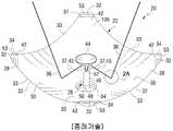
도 1은 종래의 태양열 집열기 장치의 평면도이다.
도 2는 종래의 태양열 집열기의 등축도이고, 도 2a는 태양열 집열기의 오목면에 입사한 태양 광선의 확대도이다.
도 3은 본 발명의 태양 거울을 도시한 도 2와 유사한 도이다.
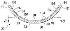
도 4는 본 발명의 코팅을 가지는 유리편의 등축도로서, 도 4의 코팅은 명확성을 위하여 제거된 부분을 가진다.
도 5a는 진공 몰드의 개방단 상에 장착된 도 4의 유리편을 가지는 진공 몰드의 측면도이고, 도 5b는 진공 몰드 내부에 본 발명의 성형 유리 기판을 가지는 진공 몰드의 단면도이다.
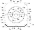
도 6은 성형 유리 기판의 주변부에 원주 방향 압축 스트레인(strain)의 패턴을 도시하는 본 발명의 성형 유리 기판의 평면도이다.
도 7은, 무엇보다도, 성형 유리 기판의 전이 스트레인 선을 도시한, 도 6의 7-7선을 따라 취해진 도이다.
도 8은 성형 유리 기판의 원주 방향 인장 스트레인 및 반경 방향 인장 스트레인을 도시한 도 7의 8-8선을 따라 취해진 도이다.
도 9a는 도 4에 도시된 유리편의 한 세그먼트의 등축도이고, 도 9b는 유리편이 성형 유리 기판 내로 성형된 후의 도 9a에 도시된 세그먼트의 등축도이고, 코팅은 피크(peak)와 밸리(valley)를 가지며, 도 9c는 본 발명의 지시에 따라 제조된 성형 유리 기판의 세그먼트를 도시한 도 9b와 유사한 도이고, 코팅은 감소된 수의 피크(peak)와 밸리(valley), 감소된 피크 높이 및 감소된 밸리 깊이를 가진다.
도 10은 코팅 유리를 세그먼트들로 절단하는 것을 포함하는 본 발명의 성형 태양 거울을 제조하기 위한 본 발명의 또 다른 실시예를 도시한 도 4와 유사한 도이다.
도 11은 도 10의 코팅 유리로부터 절단된 세그먼트들을 성형하기 위한 본 발명의 실시예에 사용될 수 있는 유리 시트 압착 장치의 등축 평면도이다.
도 12는 성형 유리 세그먼트들을 결합시킴으로써 제조된 본 발명의 성형 태양 거울의 평면도이다.
도 13은 성형 유리 세그먼트들로 제조된 본 발명의 성형 태양 거울을 도시한 도 3과 유사한 도이다.
도 14는 원형 유리편 상부의 코팅 실드(shield)를 도시한 도 4와 유사한 도이다.
도 15는 성형 유리 기판의 바닥부와 전이 스트레인 선 사이 위치에서의 성형 유리 기판의 평단면도이고, 성형 유리 기판의 원주 방향 인장 및 반경 방향 인장 영역에서의 균열들을 도시한 도이고, 코팅의 크로스 해칭은 명확성을 위하여 도시되지 않는다.
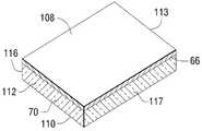
도 16-19는 유리편들의 한 면 또는 양면 상에, 그리고 선택적으로 유리편의 한면 상부의 반사면 상에, 본 발명의 장벽 코팅 및/또는 스크래치 저항 코팅을 가지는 도 4에 도시된 형태의 평면 유리편 부분들의 측단면도이다.
도 20은 본 발명의 장벽층을 가지는 광전지 부분의 측면도이다.1 is a plan view of a conventional solar collector device.
FIG. 2 is an isometric view of a conventional solar collector, and FIG. 2 (a) is an enlarged view of a sunlight incident on a concave surface of the solar collector.
Figure 3 is a view similar to Figure 2 showing a sun mirror of the present invention.
Fig. 4 is an isometric view of a glass piece with a coating of the present invention, wherein the coating of Fig. 4 has portions removed for clarity.
Fig. 5A is a side view of a vacuum mold having the glass piece of Fig. 4 mounted on the open end of a vacuum mold, and Fig. 5B is a cross sectional view of a vacuum mold having the shaped glass substrate of the present invention inside the vacuum mold.
6 is a plan view of a molded glass substrate of the present invention showing a pattern of circumferential compressive strain at the periphery of the shaped glass substrate.
7 is a diagram taken along line 7-7 of Fig. 6, showing, among other things, the transition strain line of a molded glass substrate. Fig.
Figure 8 is taken along line 8-8 of Figure 7 showing the circumferential tensile strain and the radial tensile strain of the shaped glass substrate.
FIG. 9A is an isometric view of one segment of the glass piece shown in FIG. 4, FIG. 9B is an isometric view of the segment shown in FIG. 9A after the glass piece has been molded into the shaped glass substrate and the coating is peaks and valleys And FIG. 9C is a view similar to FIG. 9B showing a segment of a shaped glass substrate made in accordance with the teachings of the present invention, wherein the coating has a reduced number of peaks and valleys, a reduced peak height And reduced valley depth.
10 is a view similar to FIG. 4, showing another embodiment of the present invention for manufacturing a forming sun mirror of the present invention, including cutting a coated glass into segments.
11 is an isometric top view of a glass sheet crimping apparatus that can be used in an embodiment of the present invention for forming segments cut from the coated glass of FIG.
12 is a plan view of a molding sun mirror of the present invention made by joining molded glass segments.
Fig. 13 is a view similar to Fig. 3 showing a forming sun mirror of the present invention made of molded glass segments.
Figure 14 is a view similar to Figure 4 showing a coating shield on top of a circular glass piece.
15 is a plan view of the shaped glass substrate at the position between the bottom of the shaped glass substrate and the transition strain line and showing the cracks in the circumferential tensile and radial tensile regions of the shaped glass substrate, Are not shown for clarity.
Figures 16-19 show a planar glass of the type shown in Figure 4 having a barrier coating and / or a scratch resistant coating of the present invention on one or both sides of the glass pieces, and optionally on the reflective surface of one side of the glass piece. Fig.
20 is a side view of a photovoltaic cell portion having a barrier layer of the present invention.
이하의 논의에서, "내부", "외부", "왼쪽", "오른쪽", "위", "아래", "수평", "수직" 등과 같은 공간적 또는 방향적 용어는 그것이 도면에 도시된 바와 같이 본 발명과 관련된다. 그러나, 본 발명은 여러 가지 대안적 방향을 추정할 수 있으며, 따라서 그러한 용어는 한정으로 고려되어서는 안되는 것으로 이해되어야 한다. 추가로, 명세서 및 청구범위에 사용된, 치수를 표현하는 모든 수들, 물리적 특성 등등은 용어 "약"에 의해 모든 경우에 변경되는 것으로 이해되어야 한다. 따라서, 반대로 표현되지 않는 한 이하의 명세서 및 청구범위에서 설정된 수치 값은 본 발명에 의하여 획득되도록 요구된 소정의 특성들에 따라 변화할 수 있다. 최소한, 그리고 청구범위의 영역과 등가물인 독트린의 출원을 제한하려는 시도로서가 아니라, 각 수치 파라미터는 적어도, 기록된 중요한 자리수들의 숫자에 비추어 그리고 보통의 라운딩 기술을 적용하는 것에 의해 해석되어야 한다. 더욱이, 여기 기술된 모든 범위들은 내포된 임의의 그리고 모든 하위-범위를 포함하는 것으로 이해되어야 한다. 예를 들면, "1 내지 10"의 정해진 범위는 최소값 1 및 최대값 10 (를 포함하여) 사이에 임의의 그리고 모든 하위-범위를 포함하는 것으로 생각되어야 한다; 즉, 모든 하위-범위는, 예를 들면 1 내지 6.7, 또는 3.2 내지 8.1, 또는 5.5 내지 10과 같이, 1 이상의 최솟값으로 시작하여 10 이하의 최댓값으로 끝난다. 또한, 여기서 사용된 바와 같이, 용어 "상부에 가해진", 또는 "상부에 제공된"은 반드시 표면 접촉으로는 아니나 그 상에 가해지거나, 또는 제공된다는 것을 의미한다. 예를 들면 기판 또는 기판 표면 "상부에 가해진" 물질은, 그 증착된 물질과 기판 또는 기판 표면 사이에 배치된 동일하거나 서로 다른 구성들의 1 이상의 다른 물질들이 존재할 수도 있음을 배제하지 않는다.In the following discussion, the terms spatial or directional, such as "inside," "outside," "left," "right," "above," "below," " As well as to the present invention. It should be understood, however, that the present invention may be susceptible of various alternative orientations, and such terms are not to be considered limiting. In addition, all numbers expressing dimensions, physical characteristics, etc. used in the specification and claims are to be understood as being modified in all instances by the term "about ". Accordingly, unless expressly stated to the contrary, the numerical values set forth in the following specification and claims may vary depending upon the particular characteristics desired to be obtained by the present invention. At the very least, and not as an attempt to limit the doctrine's application to the equivalents of the claims, each numerical parameter should at least be construed in light of the number of significant digits recorded and by applying ordinary rounding techniques. Moreover, all ranges described herein are to be understood as including any and all sub-ranges implied. For example, a given range of "1 to 10" should be considered to include any and all sub-ranges between the minimum value 1 and the maximum value 10 (inclusive); That is, all sub-ranges start with a minimum of 1 or more and end with a maximum of 10 or less, such as 1 to 6.7, or 3.2 to 8.1, or 5.5 to 10. Also, as used herein, the term " applied on top, " or "provided on top" means not applied to, or provided over, surface contact. For example, a substrate or substrate "topside" material does not preclude the presence of one or more other materials of the same or different configurations disposed between the substrate and the substrate surface.
본 발명의 수개의 비-제한 실시예들을 논의하기에 앞서, 본 발명이 다른 실시예들을 수용할 수 있기 때문에 본 발명은 여기서 도시되고 논의된 특별한 비-제한 실시예들의 상세한 설명에 대한 적용으로 제한되지 않는 것으로 이해된다. 추가로, 본 발명을 논의하기 위하여 여기에 사용된 전문 용어들은 설명을 위한 것이며, 제한하기 위한 것이 아니다. 또한 추가로, 다르게 표현되지 않는 한, 이하의 논의에서 동일한 숫자는 동일한 구성 요소를 나타낸다.Before discussing several non-limiting embodiments of the present invention, it should be understood that this invention is not limited to the application of the detailed description of the specific non-limiting embodiments shown and discussed herein, ≪ / RTI > In addition, the terminology used herein for the purpose of discussing the present invention is intended to be illustrative, not limiting. In addition, unless otherwise expressed, the same numbers in the following discussion refer to the same elements.
본 발명의 장벽 코팅 또는 장벽층은 이하에서 상세히 논의된 실리콘-알루미늄 산화물 코팅이다. 본 발명의 실리콘-알루미늄 산화물 코팅은 또한, 예를 들면 스크래치 등과 같은 기계적 손상, 및 예를 들면 7-14 범위 내, 특히 9-14 범위 내의 pH를 가지는 물질들로부터의 화학적 에칭 등과 같은 화학적 손상에 대한 보호를 제공한다. 본 발명의 코팅에 대한 장벽 특성과 관련한 이하의 논의는 그밖에 다르게 표현되지 않는 한 본 발명의 코팅에 대한 스크래치 저항 특성에 적용 가능하다. 이와 관련하여, 50 나노미터(이하에 "nm"으로 언급함) 이하의 코팅 두께에서, 본 발명의 실리콘-알루미늄 산화물은 기계적 손상 및 화학적 손상에 대한 저항성을 상실한다.The barrier coating or barrier layer of the present invention is a silicon-aluminum oxide coating discussed in detail below. The silicon-aluminum oxide coating of the present invention can also be used for chemical damage such as, for example, scratches, and chemical damage, such as chemical etching from materials having a pH in the range of 7-14, Provide protection against. The following discussion of the barrier properties for the coatings of the present invention is applicable to the scratch resistance properties of the coatings of the present invention unless otherwise indicated. In this regard, at coating thicknesses below 50 nanometers (hereinafter referred to as "nm"), the silicon-aluminum oxide of the present invention loses its resistance to mechanical and chemical damage.
논의를 명백히 하기 위하여, 용어 "알칼리 장벽층 또는 코팅" 및 "나트륨 이온 장벽층 또는 코팅"은 상부에 알칼리 또는 나트륨 침전물의 형성을 방지 또는 제한하기 위한 장벽으로서 역할하는 층 또는 코팅을 의미하며, 그 상부, 또는 그 상에 층 또는 코팅이 가해져 있는 표면에 대해 기계적 및/또는 화학적 손상을 방지 또는 제한하는 저항성을 선택적으로 갖는다. "보호 층 또는 코팅"은, 기계적 및/또는 화학적 손상을 방지 또는 제한하는 저항성을 갖는 층 또는 코팅을 의미하며, 그리고/또는 상부에 층 또는 코팅이 가해져 있는 표면 상에 알칼리 또는 나트륨 침전물의 형성을 제한할 수 있다.The term "alkali barrier layer or coating" and "sodium ion barrier layer or coating" refer to a layer or coating that acts as a barrier to prevent or limit the formation of alkali or sodium deposits on the top, Optionally has a resistance to prevent or limit mechanical and / or chemical damage to the top, or surface on which the layer or coating is applied. "Protective layer or coating" means a layer or coating having resistance to prevent or limit mechanical and / or chemical damage, and / or the formation of an alkali or sodium precipitate on the surface on which the layer or coating is applied Can be limited.
본 발명의 비-제한 실시예들은, 마그네트론 스퍼터링 진공 증착(이하에 "MSVD"로 언급됨) 코팅 공정을 사용하여 기판 표면 상에, 또는 상부에 코팅 또는 층 또는 막을 가하는 것이 논의될 것이며, 그것은 알칼리 이온에 대한 장벽으로, 예를 들면 나트륨 이온이 대기 중의 습기와 반응하는 것과 나트륨 이온이 상술된 바와 같이 유리 표면의 화합물 침전물인 나트륨 화합물, 예를 들면 수산화 나트륨 및 탄산나트륨 등으로 변환하는 것을 방지한다. 인지되는 바와 같이, 본 발명은 코팅 공정으로 제한되지 않으며, 코팅 공정은 유리 표면 상에, 또는 상부에 알칼리 이온, 예를 들면 나트륨 이온, 장벽 막 또는 층을 가하거나 코팅하는 임의의 코팅 공정일 수 있다.Non-limiting embodiments of the present invention will discuss the application of a coating or layer or film on or onto a substrate surface using a magnetron sputtering vacuum deposition (hereinafter referred to as "MSVD ") coating process, As a barrier to ions, for example, sodium ions react with moisture in the atmosphere and sodium ions are prevented from converting to sodium compounds, such as sodium hydroxide and sodium carbonate, which are compound precipitates on the glass surface, as described above. As will be appreciated, the present invention is not limited to a coating process, and the coating process can be any coating process for applying or coating an alkali ion, for example, a sodium ion, barrier film or layer, have.
이하의 논의는 알칼리 이온 장벽 코팅 또는 장벽층을 가하는 것에 관한 비-제한 실시예로 나아간다. 그밖에 달리 표시되지 않는다면, 논의는 스크래치 저항 코팅 또는 층들에 적용될 수 있다.The following discussion proceeds to non-limiting embodiments relating to the application of an alkali ion barrier coating or barrier layer. If not otherwise indicated, the discussion can be applied to scratch resistant coatings or layers.
인지되는 바와 같이, 유리 기판 또는 유리편은 본 발명으로 제한되지 않고, 유리는 임의의 구성의 유리일 수 있다; 유리는 투명하거나 채색된 유리일 수 있으며, 그리고/또는 유리는 어닐(anneal), 열 강화 또는 단련된 유리일 수 있다. 유리 편 또는 기판은 임의의 형상, 두께 및 크기를 가질 수 있다. 본 발명의 비-제한 실시예들은 그 실시예들이 태양 반사 거울과 관련된 것으로서 제시된다. 그러나, 본 발명은 거기에 제한되지 않고, 본 발명은 상업용과 주거용 창문; 유리 샤워기 도어; 공중, 우주, 지상 및 수중 운송수단용 투명체(transparencies); 코팅된 병; 박막 광기전력형 응용을 위한 코팅 유리; 흐림-방지 상업용 냉장고를 위한 전기 가열된 유리, 및 가구 이용을 위한 유리 제조시에 실행될 수 있다.As will be appreciated, the glass substrate or glass piece is not limited to the present invention, and the glass can be any configuration of glass; The glass can be transparent or colored glass, and / or the glass can be annealed, heat strengthened or tempered glass. The glass piece or substrate may have any shape, thickness and size. Non-limiting embodiments of the present invention are presented as being related to sun-reflecting mirrors. However, the present invention is not limited thereto, and the present invention is applicable to commercial and residential windows; Glass shower door; Transparencies for air, space, ground and underwater vehicles; Coated bottles; Coated glass for thin film photovoltaic applications; Electrical heated glass for blur-resistant commercial refrigerators, and glass for furniture use.
이하의 논의에서, 성형 태양 반사 거울은 포물면형 반사 거울로서 언급되며, 그러나 본 발명은 거기에 제한되지 않고, 본 발명은 그밖에 다르게 표시되지 않는 한, 굴곡 반사면 및 초점 또는 초점 영역을 가지는 임의의 거울로 실행될 수도 있으며, 예를 들면 본 발명으로 제한되지는 않으나, 포물면형 거울 및 구형 거울로 실행될 수 있다. "초점" 및 "초점 영역"은 거울로부터 반사된 태양광선의 80% 이상이 수렴하는 위치로서 형성된다. "초점 영역"의 크기 및 위치가 본 발명으로 제한되지 않으며, 본 발명의 한 비-제한 실시예에서, 초점 영역은 거울의 반사 영역의 5분의 1(1/5) 보다 작다.In the following discussion, molded sun mirrors are referred to as parabolic reflective mirrors, but the present invention is not so limited and the present invention is not limited to any particular mirrors, Mirror, and may be implemented with a parabolic mirror and a spherical mirror, for example but not limited to the present invention. The "focus" and "focus area" are formed as positions where more than 80% of the sun rays reflected from the mirror converge. The size and location of the "focus area" is not limited to the present invention, and in one non-limiting embodiment of the present invention, the focus area is smaller than one fifth (1/5) of the reflection area of the mirror.
도 1에 태양 에너지를 전기 에너지로 변환시키는 종래 기술의 성형 태양열 집열기(20)(도 2 참조)의 어레이(array)(18)가 도시된다. 본 발명은 어레이(18) 내의 태양열 집열기(20)을 결합시키는 방식으로 제한되지 않으며 공지의 임의의 기술이 어레이(18) 내의 태양열 집열기(20)를 결합시키는데 사용될 수 있다. 추가로 본 발명은 어레이(18) 내의 태양열 집열기(20)의 숫자에 제한되지 않으며, 예를 들면 본 발명은 하나의 태양열 집열기(20)와, 어레이(2), (3), (4), (5), (10), (20), (50) 이상 및 임의의 태양열 집열기의 숫자 조합에서 실행될 수 있다. 또한 추가로, 본 발명은 고정 위치에서 임의의 편리한 방식으로 장착된 태양열 집열기(20)의 어레이(18), 또는 태양열 집열기를 태양 에너지에 최대한 노출시키기 위하여 태양의 경로를 따르는 임의의 편리한 방식으로 장착된 태양열 집열기의 어레이(18)를 고려한다. 태양열 집열기(20) 각각은 동일물을 가질 수도 있으나 태양열 에너지가 다른 대체 에너지원, 예를 들면 전기 에너지 또는 열로 변환되는 특별한 영역으로 태양열 에너지를 향하도록 하기 위해 다른 디자인을 가질 수도 있다.Figure 1 shows an
도 2를 참조하면, 태양열 집열기(20) 각각은 태양열 에너지를 전기 에너지로 변환시키는 장치(26) 상에 태양열 에너지의 초점을 맞추는 성형 반사 거울, 예를 들면 포물면형 거울(22) (또한 여기서 "1차 거울"로서 언급됨)을 포함한다. 포물면형 거울(22)은 포물면형 유리 기판(28)을 포함한다. 유리 기판(28)은 바람직하게는 0.020 중량 퍼센트보다 작은 전체 철 함량, 전자기 스펙트럼의 가시 범위, 예를 들면 350 내지 770 나노미터("nm")에서, 그리고 전자기 스펙트럼의 적외선("IR") 범위, 예를 들면 770nm 보다 크고 2150nm까지에서, 90% 투과율, 그리고, 가시 범위 및 IR범위에서 낮은 흡수율, 예를 들면 2% 이하를 가진다.2, each of the
선행의 광학 특성을 가지는 유리들이 2008년 11월 21에 제출된 미국 특허 출원 제 12/275,264호 및 미국 특허 제 5,030,594호에 개시되며, 그 전체 서류가 여기서 참고 문헌으로 병합된다. 피피지 인더스트리즈 인코포레이티드(PPG Industries, Inc.)가 "STARPHIRE" 및 "SOLARPHIRE PV"라는 상표로 상기 특성을 가지는 유리를 판매하고 있다. 성형 유리 기판(28)은 오목면(30) 및 대향의 볼록면(32)을 가진다. 성형 유리 기판(28)의 주변부는 측부(33)를 구비하도록 성형된다. 도 1에 도시된 바와 같이, 인접한 태양열 집열기(20)의 측부(33)는 반사면들과 주어진 영역과의 커버리지를 최대화시키도록 서로 접촉되어 있다. 반사 코팅, 층 또는 막(34)(도 2에 명백히 도시)이 성형 유리 기판(28)의 볼록면(32) 상부에 그리고 바람직하게는 그 상에 있다. 반사막(34)은 금속, 예를 들면 은, 알루미늄, 니켈, 스테인리스 스틸(stainless steel) 또는 금일 수 있으나 이에 제한되지는 않는다. 보통 반사막(34)은 은이다.Glass having the preceding optical properties are disclosed in U.S. Patent Application No. 12 / 275,264 and U.S. Patent No. 5,030,594, filed on November 21, 2008, the entire document of which is incorporated herein by reference. PPG Industries, Inc. sells glass with the above properties under the trademarks " STARPHIRE "and" SOLARPHIRE PV ". The shaped
계속 도 2를 참조하면, 광선(36)으로 표시된 평행한 태양 에너지 광선이 오목면(30) 상에 입사한다. 광선(36)의 일부(37)가 오목면(30)으로부터 변환 장치(26)로 반사되고, 일부(38)는 오목면(30)과 성형 유리 기판(28)을 통과하며, 그리고 반사광(43)(도 2 참조)으로서 성형 유리 기판(28)을 통하여 다시 반사막(34)의 표면(42)으로부터 변환 장치(26)로 반사된다. 태양 에너지 광선은, 오목면(30) 상에 입사한 무한한 수의 평행한 태양 에너지 광선들 대신 간단 명료함을 위하여 두 개의 광선(36)으로 도 2에 도시된다. 추가로, 당업자가 인지하고 있는 바와 같이, 성형 유리 기판(28)의 오목면(30) 및 볼록면(32) 사이로 태양 광선이 반사되며; 그러나 투명 기판 상에 입사하고 그를 통과하는 태양 에너지 광선 의 투과, 흡수 및 반사에 관한 상세한 논의는 공지 기술에 잘 공지되어 있는 바 추가의 논의가 필요하지 않은 것으로 사료된다.Continuing with reference to FIG. 2, a parallel solar energy beam, indicated by
도 1 및 2에 도시된 실시예에서, 변환 장치(26)는 포물면형 거울 또는 1차 거울(22)의 초점과 관련하여 배치되는 성형 2차 거울(44), 그리고 1차 거울(44)의 초점 영역에 있는 광학 봉 또는 광 바(light bar)(46) (도 2에 명백히 도시)를 포함한다. 다중-접합 태양 전지(48)들은 광 바(46)의 단부(50)에 배치된다. 이 배열로 반사 광선(37 및 43) (도 2a 참조)은 2차 거울(44) 상에 입사하고; 2차 거울은 광선(37 및 43)을 광 바(46)(도 2에 명백히 도시)의 단부(52)로 반사시킨다. 광선(37 및 43)은 광 바(46)를 통과하여 광 바(46)의 단부(50)로 나가고, 그리고 태양 에너지를 전기 에너지로 변환시키기 위하여 태양 전지(48) 상에 입사한다. 당업자에게 인지되어 있는 바와 같이, 태양 전지(48)는 2차 거울(44)을 제거하기 위하여 1차 거울(22)의 초점에 위치될 수 있다.In the embodiment shown in Figures 1 and 2, the
본 발명은 2차 거울의 형상을 제한하지 않는다. 더욱 특히, 본 발명의 실행에서 2차 거울은 바람직하게는 평면 반사면을 가진다. 본 발명의 실행에서, 2차 거울은 태양 반사 코팅면, 예를 들면 은 코팅면을 가지는 평면 유리의 원형편이었다. 그러나, 본 발명은 오목면 및 볼록면 및 그 표면들 중 적어도 하나, 예를 들면 볼록면 상에 반사 코팅을 가지는 성형 2차 거울을 사용하여 실행될 수 있다.The present invention does not limit the shape of the secondary mirror. More particularly, in the practice of the present invention, the secondary mirror preferably has a planar reflective surface. In the practice of the present invention, the secondary mirror was the original form of a flat glass with a sun-reflecting coated surface, for example a silver coated surface. However, the invention may be practiced using a concave and convex surface and at least one of its surfaces, for example a molded secondary mirror having a reflective coating on the convex surface.
도 1을 참조하면, 커버(60) (도 1의 왼쪽 상부 코너에 부분적으로 도시)가 태양열 집열기(20)의 포물면형 거울(22)의 오목면(30) 상에 먼지 및 물이 증착되는 것을 방지하기 위하여 태양열 집열기의 어레이 상부에 지지된다. 종래 기술에 공지된 바와 같이, 커버(60)는 전자기 스케일(scale)의 가시 및 IR 파장 범위에 대해 투과된다. 선택적으로 1차 거울(22)의 성형 유리 기판(28)은 광 바(46) 및 태양 전지(48)에 대한 접근성을 제공하기 위하여 성형 유리 기판(28)의 기저에 차단부(cut out)(64)(도 2에 명백히 도시)를 가진다."Description of The Availabl Technology(활용가능한 기술에 대한 설명)"라는 제목의 섹션에서 위에 논의된 바와 같이, 현재 활용가능한 태양열 집열기에 대한 제한은 1차 거울(22) 및 2차 거울(44)에 대하여 소다-석회 실리카 유리 기판을 사용한다는 것이다. 유리 기판은 보통 플로트 유리 공정(float glass process), 예를 들면 미국 특허 제 3,333,936호 및 4,402,722호에 기술된 유리 제조 공정에 의해 제조된 연속 유리 리본(ribbon)으로부터 절단된 절단 유리편들이며, 그 특허 전체가 여기에 참고 문헌으로 병합되어 있다. 종래 기술에서 잘 공지되어 있는 바와 같이, 소다-석회 실리카 유리는 나트륨 이온을 포함한다. 예를 들면 1차 거울(22)에 침투하는 태양 광선(36)에 대한 장시간 환경 노출은 성형 유리 기판(28)을 가열시키고, 포물면 성형 기판(28)을 형성하기 위한 유리의 가열은 나트륨 이온이 성형 유리 기판(28)으로부터 확산 또는 침출되도록 하는 에너지를 제공한다. 표면(30 및 32)에서 성형 유리 기판(28)으로부터 침출한 나트륨 이온은 대기중의 수분과 반응하고, 나트륨 이온을 나트륨 화합물, 예를 들면 수산화 나트륨 및 탄산 나트륨으로 변환시킨다. 나트륨 화합물은 성형 유리 기판(28)의 표면 상에 침전물로서 증착한다. 성형 유리 기판(28)의 오목면(30) 상의 나트륨 화합물 침전물은 성형 유리 기판(28)의 가시광 투과를 감소시키고, 나트륨 화합물 침전물을 가지는 오목면(30)의 부분들을 반사광선(37 및 43)이 1차 거울(22)의 초점으로부터 멀리 또는 2차 거울(44)로부터 멀리 향하게 하는 비-정반사 또는 확산면으로 만든다. 볼록면이 반사 코팅(34)과 그 반사 코팅 상부에 보호 플라스틱 코팅 또는 막(53)(도 2에만 도시)을 가지기 때문에, 1차 거울(22)의 볼록면(32) 상부에는 나트륨 화합물 침전물이, 있다 하더라도 아주 적게 있다. 종래 기술에서 공지된 바와 같이, 보호 코팅(53)은 환경으로부터 반사 코팅(34)을 보호하고, 본 발명의 실행에서, 보호 코팅(53)은 유리 기판(28)의 볼록면(32)에서의 나트륨 이온이 나트륨 화합물을 형성하기 위하여 환경과 반응하는 것을 제한한다. 반사 코팅(34) 용 보호 코팅(53)이 나트륨 화합물 침전물의 형성을 방지한다 하더라도, 본 발명은 유리 기판(28)의 볼록면(32) 상에서의 본 발명의 실행을 고려한다. 현재 인지될 수 있는 바와 같이, 소다-석회 실리카 유리로 제조된 2차 거울(44)은, 2차 거울 상의 나트륨 화합물 침전물이 1차 거울(22)로부터의 반사 광선을 광 봉(46)으로부터 멀리 향하게 한다는 점을 제외하고는 1차 거울(22)과 동일한 결점을 가질 수 있다.Referring to Figure 1, a cover 60 (partially shown in the upper left corner of Figure 1) is used to deposit dust and water on the
도 3을 참조하면, 본 발명의 하나의 비-제한 실시예에서, 1차 거울(22)의 성형 유리 기판(28)의 오목면(30)은 나트륨 장벽 코팅 또는 층 또는 막(66)을 가진다.Referring to Figure 3, in one non-limiting embodiment of the present invention, the
도 4를 참조하면, 나트륨 장벽 코팅(66)은 원형의 성형 평면 유리편(70) 표면(68) 상부에 그리고 바람직하게는 상에 가해진다. 유리편(70)의 표면(68)은 성형 유리 기판(28)의 오목면(30)에 나타내어진다. 본 발명의 실행시, 장벽층(66)은 바람직하게는 전자기 파장의 가시 및 IR 스펙트럼의 90% 이상, 더욱 바람직하게는 95% 이상, 가장 바람직하게는 100%를 투과시킨다. 장벽층(66)은 바람직하게는 유리의 성형 또는 벤딩 온도, 예를 들면 소다-석회 실리카 유리를 위하여 화씨 1220°("F") 보다 더 높은 온도를 이겨낼 수 있다. 추가로, 장벽층(66)은 바람직하게는 유리편(70)의 성형 중에 크랙(crack) 및/또는 버클(buckle)이 발생하지 않으며, 그 결과 알칼리 이온, 예를 들면 나트륨 이온이 장벽 코팅(66) 내의 크랙을 통하여 이동할 수 없게 되고, 버클링(buckling)이 광선(37 및 43)을 포물면형 거울(22)의 초점으로부터 상당히 멀리 편향시키지는 않는다. 장벽 코팅(66) 내의 크랙 및 장벽 코팅(66)의 버클링에 관한 논의가 이하에 더욱 상세히 주어진다.Referring to FIG. 4, a
본 발명의 하나의 비-제한 실시예에서, 원형의 평면 유리편(70)은 직경 18인치(45.72 센티미터("cm")) 및 두께 0.083인치(2.1 밀리미터("mm"))를 가진다. 85 원자퍼센트 실리콘 및 15 원자퍼센트 알루미늄의 산화물의 800 옹스트롬(angstrom) 두께의 장벽 코팅(66)이 MSVD 코팅 공정에 의하여 유리편(70)의 표면(68) (성형 유리 기판(28)의 오목면(30)인 것으로 나타내어짐) 상에 증착되었다. 성형 유리 기판(28)의 볼록면(32)인 것으로 나타내어진 코팅 유리편의 표면(72)은 진공-성형 몰드(76)(도 5a 참조)의 개방 단부(74) 상에 배치되었다. 유리편(70) 및 몰드(76)가 로(미도시) 내에서 가열되어 유리편이 1220℉ (섭씨(C) 660°)의 온도로 가열되었다. 코팅 유리편(70) 및 진공-몰드(76)는 임의의 보통 방식으로 균일하게 가열되었다. 코팅 유리편(70) 및 진공-몰드(76)가 1220℉ (660℃)로 가열된 후, 코팅(66)(도 5b )을 가지는 성형 유리 기판(28)을 제공하기 위하여, 가열된 유리편(70)이 진공 몰드(76)의 내부(78)로 힘을 받도록 간격형성된 홀들(77)에 의하여 공기가 몰드(76)의 내부(78)로부터 배출되었다. 가열된 성형 유리 기판은 성형 유리 기판을 어닐(anneal)하기 위하여 냉각 조절되었다. 인지될 수 있는 바와 같이, 본 발명은 유리편(70) 및 진공 몰드(76)를 별개로 가열하고, 그 후 진공 몰드(76)의 개방 단부(74) 상에 유리편(70)을 배치하며, 그리고 그 유리편(70)을 상술한 바와 같이 성형하는 것을 고려하였다. 유리를 가열하고 진공 몰드 내에서 유리를 성형하고, 유리 및 코팅 유리를 어닐링하기 위한 공정 및 장비는 종래의 기술에 잘 공지되어 있고 상세한 논의가 필요치 않은 것으로 사료된다.In one non-limiting embodiment of the present invention, the circular
성형 공정 동안, 평면 유리편(70)(도 4 참조)이 진공 몰드(76)의 내부(78)로 기울거나 당겨질 때, 평면 유리편(70)의 중앙부(79)가 스트레치된다. 스트레칭의 결과, 성형 유리 기판(28)의 기저 영역(80)에서의 두께는(도 5b 참조)(도 3에서의 홀(64) 및 도 4에서의 유리편(70)의 중앙부(79)에 대응하여) 평면 유리편(70)(도 4 참조)의 중앙부(79) 두께의 80%이고, 성형 유리 기판(28)의 마진 에지(marginal edge)(81) 두께는(도 5b 참조) 평면 유리편(70)의 마진 에지(82) 두께의 105%이다(도 4 참조). 인지될 수 있는 바와 같이, 성형 유리 기판(28)의 마진 에지(81)는 강하게 당겨지고 광 왜곡(optical distortion)을 가진다. 본 발명의 실행에서, 그에 제한되지는 않으나, 성형 유리 기판(28)의 세그먼트(83)(도 5b 참조)가 강하게 당겨지고 광 왜곡된 유리의 일부분들을 제거하기 위하여 그리고 어레이(18)에서 도시된 바와 같이 성형 태양 거울(20)의 인접한 것들의 측부(33)를 서로 대향하게 위치시키기 위하여 절단되었다(도 1 참조). 본 발명의 실행에서, 그에 제한되지는 않으나, 성형 유리 기판의 주변 에지(84)로부터 기저(80) 쪽으로 측정된 약 2인치의 섹션(80)(도 5b 참조)이 절단되었다. 성형 유리 기판(28)의 주변 에지의 추가 부분들이 성형 유리 기판(28)의 측부(33)(도 3 참조)를 제공하기 위하여 제거되었다. 컷 아웃 또는 홀(64)(도 3 참조)이 성형 유리 기판(28)의 기저 영역(80)(도 5b 참조)에서 절단되었다. 그 다음, 반사 코팅, 예를 들면 은 층(34)이 성형 유리 기판(28)의 볼록면(32) 상부에 가해졌고(도 3 참조), 보호 막(53)(도 2 참조)이 반사 코팅(34) 상에 가해졌다.During the molding process, the
인지된 바와 같이, 본 발명은 성형 유리 기판(28)의 기저 영역(80)(도 5b 참조) 내의 홀(64)을 절단하고, 성형 유리 기판의 주변 에지(24)를 절단하는 공정에, 또는 성형 유리 기판(28)의 볼록면(32) 상부에 반사 코팅(34) 및 보호 코팅(53)을 가하는 코팅 공정에 제한되어서는 안되며, 종래 기술에서 공지된 임의의 컷팅 및/또는 코팅 기술이 본 발명의 실행시 사용될 수 있다.The present invention can be applied to the process of cutting the
1200°-1300℉ (649 -704℃)의 범위 내의 온도에서, 유리편(70)은 열연화성 또는 점성이고; 다른 한편, 본 발명의 장벽 코팅(66), 예를 들면 산화 알루미늄 및 실리콘은 내열성 물질이며 1200°-1300℉ (649°-704℃)의 범위 내의 온도에서 치수상 계속 안정적이다. 여기서 사용된 바와 같이, 용어 "치수상 안정적"은 유리편의 가열 동안 및/또는 후 코팅의 물리적 치수가 ±5% 이상, 바람직하게는 ±2% 이상 변하지 않는다는 것을 의미한다. 평면 유리편(70)을 성형 유리 기판(28)으로 성형하는 동안, 도 6-8에 도시된 스트레인 패턴은 성형 유리 기판(28) 내에서 성장한다. 도 6-8을 참조하면, 필요에 따라, 숫자(90)에 의해 도시된 반경 방향 인장 스트레인이 성형 유리 기판(28)의 기저부에 존재하며(도 8 참조), 숫자(92)에 의해 도시된 원주 방향 압축 스트레인이 성형 유리 기판(28)의 주변부(84)에 존재한다. 장벽 코팅(66)은 유리 기판의 오목면에 점착됨으로 인하여 스크레스를 겪는다. 성형 유리 기판(28)의 주변부(84)로부터의 거리가 성형 유리 기판(28)의 기저 영역(80)을 향한 방향으로 증가할 때(도 7 참조), 반경 방향 인장 스트레인(90)은 일반적으로 계속 동일하며, 그리고 숫자(102)로 나타내어진 원주 방향 압축 스트레인(도 8 참조)이 유리에서 시작하고 반경 방향 인장 스트레인(도 8 참조)이 유리에 존재하는 도 7에서, 원주 방향 압축 스트레인(92)은 "전이선(transition line)"으로 나타내어지고 숫자(94)로 확인되는 위치까지 감소한다. 논의 중인 성형 유리 기판(28), 예를 들면 직경 18인치(45.72cm) 및 두께 0.083인치(2.1mm)를 가지는 평면 유리편(70)으로 제조된 성형 유리 기판(28)에 대하여, 전이선(94)은 평면 유리편(70)의 중심으로부터, 즉 중앙부(79)의 중심으로부터 약 3인치(7.6cm) 평면 유리편(70)의 위치에 대응하는 성형 유리 기판(28) 상의 위치에 있다. 성형 유리 기판(28)의 기저 영역(80)을 향한 방향에서 전이선(94)으로부터의 거리가 증가할 때, 성형 유리 기판은 숫자(102)로 나타내어진 증가하는 원주 방향 인장 스트레인을 가지고 반경 방향 인장 스트레인(90)을 가진다(도 8 참조).At a temperature in the range of 1200 ° to 1300 ° F (649 ° -704 ° C), the
당업자에게 인지된 바와 같이, 성형 유리 기판(28) 내의 스트레인은 임의의 편리한 방법으로 측정될 수 있다. 본 발명의 실행에서, 논의 중인 성형 유리 기판(28)의 스트레인은 ANSYS 유한 요소 컴퓨터 프로그램을 사용하여 계산되었다.As will be appreciated by those skilled in the art, the strain in the shaped
성형 유리 기판(28)의 원주 방향 압축 영역(103) 내의 나트륨 장벽 코팅(66), 즉 성형 유리 기판(28)의 주변부(84) 및 전이선(94) 사이의 영역(도 7 참조)은 유리에서 압축 스트레인에 수직한 반경 방향으로 버클링을 가지는 것으로 관측되었다. 전이선(94)의 위치에서, 장벽 코팅(66)이 반경 방향 크랙들의 영역을 가지는 것으로 관측되었다. 성형 유리 기판(28)의 원주 방향 인장 영역(104), 즉 성형 유리 기판(28)의 전이선(94) 및 기저 영역(80) 사이의 영역에서(도 7 참조), 장벽 코팅(66)이 작은 무작위 균열 또는 크랙들을 가지는 것으로 관측되었다.The region between the
위에서 논의된 바와 같이, 최대 압축 스트레스는 성형 유리 기판(28)의 마진 에지부(81)에 있고(도 5b 및 7 참조), 장벽 코팅(68)의 최대 버클링은 마진 에지부(81)에 존재할 것임이 예기된다. 초기 성형 유리 기판(28)의 마진 에지부(81) 상에 침투한 태양 광선이 성형 유리 기판(28)의 초점 또는 초점 영역으로 거의 향하지 못하고 있는 것이 또한 관측되었다. 전술한 점에 비추어, 초기 성형 유리 기판(28)의 마진 에지부(81) 상에 침투한 태양 광선이 성형 유리 기판(28)의 초점 또는 초점 영역으로 거의 향하지 못하고 있는 것이 또한 관측되었다. 초기 성형 유리 기판의 주변 에지(84)로부터 기저 영역(80)의 중심까지 측정된 거리의 10-15%와 동일한 성형 유리 기판(28)의 주변 에지(84)로부터의 거리를 연장시킨 초기 성형 유리 기판(28)의 마진 에지부(81)가 제거되었다. 본 발명의 하나의 비-제한 실시예에서, 직경 18인치(45.72cm)를 가지는 평면 유리편(70)으로부터 성형된 성형 유리 기판(28)에 대하여, 성형 유리 기판의 주변 에지(84)로부터 기저(80)(도 5b 참조) 쪽으로 측정된 약 2인치(5.08cm)의 섹션(80)이 높은 스트레인과 광 왜곡된 유리 부분들을 제거하기 위하여 절단되었다. 성형 유리 기판의 주변 에지의 부가 부분들이 성형 유리 기판(28)의 측부(33)를 제공하기 위하여 제거되었다.As discussed above, the maximum compressive stress is at the
이제, 장벽 코팅(66)에서의 균열 및/또는 크랙에 의해 발생되는 관측 및/또는 예기되는 결함들, 및 장벽 코팅의 버클링에 의해 발생되는 관측 및/또는 예기되는 결함들로 논의가 향할 것이다. 장벽 코팅(66)의 두께를 통하여 연장된 크랙 또는 균열은 장벽 코팅(66)의 표면(108) 상에(도 7 참조) 그리고/또는 성형 유리 기판(28) 상의 오목면(30)과 장벽 코팅(66) 사이에 증착될 수 있는 나트륨 화합물 침전물을 형성하기 위하여 서로 다른 것과 상호작용하는 유리로부터 침출된 나트륨 이온 및 대기 중에서의 습기에 대한 통로를 제공할 것으로 기대된다. 장벽 코팅(66)의 표면(108) 상의 나트륨 화합물은 장벽 코팅(66)의 정반사 표면을 비-정반사 또는 확산면으로 변화시킬 수 있고, 장벽 코팅(66) 및 볼록면(30) 사이의 나트륨 화합물 침전물은 장벽 코팅(66)의 분리를 야기시킬 수 있다.It will now be discussed with observations and / or anticipated defects caused by cracks and / or cracks in the
버클링 결함은 장벽 코팅(66)의 표면(108)을 정반사면으로부터 비-정반사 또는 확산면으로 변화시킬 수 있고, 강한 버클링의 경우에는, 추가로 장벽 코팅에서의 크랙의 원인이 된다. 이하의 논의는 장벽 코팅(66)으로 향하며, 그밖에 다르게 표시되지 않는 한, 논의는 장벽 코팅의 스크래치 저항 특성(위에서 논의됨)에 적용 가능하다.Buckling defects can change the
필요에 따라 도 9a-9c를 참조하면, 원주 방향 압축(103) 영역(도 7 참조) 내에 있도록 기대되는 유리편(70) 세그먼트(110) 상의 장벽 코팅(66)(도 9a)은 측부(112 및 113) 사이에서 측정된 길이 및 측부(116 및 117) 사이에서 측정된 폭을 가진다. 유리편(70)이 성형 유리 기판(28) 내로 성형된 후, 평면 유리편(70)의 세크먼트(110)는 성형 유리 기판(28)의 세크먼트에 대응한다. 성형 유리 기판(28) 세그먼트(118)의 볼록면(32)은 평면 유리편(70) 세그먼트(110)의 측부(112 및 113) 사이에서 측정된 길이보다 약간 더 큰 세그먼트(118)의 측부(112 및 113) 사이에서 측정된 길이를 가지고, 성형 유리 기판(28) 세그먼트(118)의 볼록면(32)은 세그먼트(118)의 측부(116 및 117) 사이에서 측정된 평면 유리편(70)의 세크먼트(110)의 폭보다 더 작은 세그먼트(118)의 측부(116 및 117) 사이에서 측정된 폭을 가진다. 성형 유리 기판(28) 세그먼트(110)의 오목면(30)은 평면 유리편(70) 세그먼트(110)의 측부(112 및 113) 사이에서 측정된 길이보다 약간 더 큰 세그먼트(118)의 측부(112 및 113) 사이에서 측정된 길이를 가지고, 성형 유리 기판(28) 세그먼트(118)의 오목면(30)은 세그먼트(118)의 측부(116 및 117) 사이에서 측정된 평면 유리편(70)의 폭보다 더 작은 세그먼트(118)의 측부(116 및 117) 사이에서 측정된 폭을 가진다.9A-9C, the barrier coating 66 (FIG. 9A) on the
세그먼트(118)의 측부(112 및 113) 사이에서 측정된 볼록면(32)의 길이와 오목면(30)의 길이 사이의 증가 차가 작다. 세그먼트(118)의 측부(116 및 117) 사이에서 측정된 오목면(30)의 폭 사이의 감소 차는 세그먼트(118)의 오목측 및 볼록측의 길이 사이의 차보다 더 크다. 실예로서 본 발명을 한정하지는 않으나, 세그먼트(110)의 측부(112 및 113) 및 세그먼트(118)의 측부(112 및 113) 사이에서 측정된 팽창은 볼록측 및 오목측 양자 모두에 대하여 2-6%였다. 성형 유리 기판(28)의 둘레에서 측정된 세그먼트(110)의 측부(116 및 118) 및 세그먼트(118)의 측부(116 및 118) 사이의 수축은 13% 수축을 가지는 볼록측(32) 및 14%의 수축을 가지는 오목측(30)과 함께 14%였다. 성형 유리 기판(28)의 기저(80)에서 볼록측 및 오목측에 대한 신장은 각각 5% 및 4%였다.The increasing difference between the length of the
장벽 코팅(66)의 길이 및 폭은, 다른 한편, 동일하게 계속 유지되고 보통 스트레인으로서 언급되는 평면 유리편(70)의 대응하는 폭과 비교된 성형 유리 기판(28)의 오목 및 볼록면의 폭의 감소로 인하여 버클 형성된다. 더욱 특히, 유리는 성형 공정 동안 점성이 있고, 장벽 코팅(66)의 버클링은, 평면 유리편(70) 표면(72)의 폭에서의 감소를 수용하기 위하여 성형 유리 기판(28)의 오목면(30)의 윤곽을 주름부(120), 예를 들면 파형면(도 9b 참조)을 가지는 표면으로 바꾼다. 주름부(120)는 성형 유리 기판(28)의 오목면(30) 및 장벽 코팅(66)의 표면(108)을 도 9a에서의 정반사면으로부터 도 9b에서의 비-정반사 또는 확산면으로 바꾼다. 첫째 경우에 (도 9b), 평면 유리편 폭의 수축량이 동일하게 유지되는 한편, 장벽 코팅(66)의 두께가 증가할 때, 예를 들면 장벽 코팅이 160 나노미터("nm")의 두께로 증가할 때, 주름부(120)의 수 및 주름부(120)의 높이가 증가하고, 확산된 반사 태양 광선(37 및 43)의 퍼센트를 증가시킨다(도 2 및 도 2a 참조). 둘째 경우에(도 9c), 평면 유리편(70) 폭의 수축량이 동일하게 유지되는 한편, 장벽 코팅(66)의 두께가 감소할 때, 예를 들면 장벽 코팅(66)이 60 nm의 두께로 감소할 때, 둘째 경우(도 9c)에 주름부(120)의 수 및 주름부의 높이가 첫째 경우(도 9b 참조)의 주름부(120)의 수 및 주름부(120)의 높이보다 더 작고, 확산된 반사 태양 광선(37 및 43)의 퍼센트를 감소시킨다(도 2 및 2a 참조). 상술된 바와 같이, 원주 방향 압축 영역(103)(도 7 참조)은, 성형 유리 기판(28)의 주변부(84)로부터의 거리가 증가할 때 감소하고; 그렇기 때문에 성형 유리 기판(28)의 오목면(30)의 원주 방향 폭의 퍼센트 수축은 성형 유리 기판(28)의 주변부(84)로부터의 거리가 증가할 때 감소하며, 그리고 장벽 코팅(66)의 두께는 주름부(120)의 수 및 주름부(120)의 진폭의 증가 없이 증가할 수도 있다(도 9b 및 9c 참조).The length and width of the
본 발명의 한 비-제한 실시예에서, 장벽 코팅(66)의 두께는 나트륨 장벽 특성을 가지도록 그리고 버클링을 최소화시키도록 선택된다. 더욱 특히, 장벽 코팅(66)의 최소 두께는, 나트륨 이온이 대기 중의 습기와 반응하여 나트륨 이온이 나트륨 화합물 침전물로 변환되는 것을 방지하도록 그리고 버클링을 최소화시키도록 선택된다. 당업자에게 인지되는 바와 같이, 유리로부터 이동하여 나오는 나트륨 이온의 메커니즘은 확산 공정이며 본 발명의 목적을 위하여 관심 있는 파라미터는 유리에 존재하는 나트륨 이온의 양이다. 확산률, 알칼리 이온, 예를 들면 나트륨 이온의 크기, 그리고 나트륨 이온을 성형 유리 기판(28)의 표면으로 유도하는 에너지는 태양 거울의 사용이 장시간 사용, 예를 들면 30년이기 때문에 본 논의와 관련하여서는 고려되지 않는다.In one non-limiting embodiment of the present invention, the thickness of
전술한 내용을 기초로 하여, 유리에서 알칼리 이온 또는 나트륨 이온의 양이 유리편 두께 및 유리 구성의 함수인 바, 예를 들면 유리편(70) 또는 성형 유리 기판(28)의 두께가 증가할 때, 유리편의 나트륨 이온의 수가 증가되며, 바람직하게는 장벽 코팅의 두께 및/또는 밀도가 증가된다. 소다-석회-실리카 유리에 대하여 나트륨 농도는 일반적으로 14 중량 퍼센트이다. 본 발명의 한 비-제한 실시예에서, 포물면형 거울(22)은 0.083인치(2.1 밀리미터) 두께를 가지는 유리 기판으로 제조된다. 본 발명의 한 비-제한 실시예에서, 장벽 코팅은 85 원자 퍼센트 실리콘과 15 원자 퍼센트 알루미늄 산화물의 MSVD 코팅이다. 나트륨 이온을 나트륨 화합물 침전물로 변환시키는 환경에서 나트륨 이온이 습기와 반응하는 것을 방지하는 최소 코팅 두께는 40nm이다. 인지된 바와 같이, 최소 두께 이상의 임의의 두께는 나트륨 이온이 환경에서 습기와 반응하는 것을 방지한다; 그러나, 장벽 코팅(66)의 두께가 증가할 때, 강한 버클링이 증가한다. 본 발명의 실행에서, 원주 방향 인장 영역(104)에서의 장벽 코팅(66)(도 7 참조)은 바람직하게는 40-100nm 범위에 있고, 더욱 바람직하게는 60-100nm 범위에 있고, 가장 바람직하게는 60-80nm 범위에 있다. 40-100nm 범위 내의 코팅 두께를 가지는 동일한 코팅 구성은 기계적 및 화학적 공격 및/또는 손상에 대한 보호 코팅을 제공한다.On the basis of the above description, when the amount of alkali ions or sodium ions in the glass is a function of the glass part thickness and the glass composition, for example, when the thickness of the
위에서 논의된 바와 같이, 평면 유리편(70)은 진공 몰드(76)(도 5a 및 5b 참조)를 이용하여 성형된다. 평면 유리편(70)이 성형된 후, 성형 유리 기판은 유리가 치수상 안정되고 어닐될 때 몰드(76)로부터 제거된다. 본 발명의 목적을 위하여, 유리는 성형 유리가 형태의 변화 없이 그 자체의 중량을 지지할 수 있을 때 치수상 안정된 것으로 고려된다. 2008년 11월 21일 제출된 미국 특허 출원 제 12/275,264호 및 미국 특허 제 5,030,594호에 개시된 유리에 대하여, 유리는 1050℉의 온도에서 치수상 안정적이다. 어닐링 공정은, 장벽 코팅 및 성형 유리 기판(28)이 기판(28)을 부수거나 장벽 코팅을 파열시킴 없이 절단될 수 있도록 하기 위하여 장벽 코팅(66) 및 성형 유리 기판(28)에서의 내재 스트레스를 감소시켜 잔여 스트레스를 최소화한다. 어닐링 장비 및 평면 유리 기판(28)이 어닐링되는 속도는 본 발명에 제한되지 않으며, 종래 기술에서 공지된 임의의 어닐링 장비, 및 방법 및 속도가 본 발명의 실행에서 사용될 수 있다. 코팅 및 비코팅 유리 제품을 어닐링하는 것은 종래 기술에 잘 공지되어 있고, 추가의 논의가 필요치 않은 것으로 사료된다.As discussed above, the
본 발명은 유리편(70)의 두께에 제한되지 않고, 유리편은 임의의 두께일 수 있다. 본 발명의 바람직한 실행에서, 유리편(70)은 바람직하게는 경-중량 성형 유리 기판(28)을 제공하기 위하여 얇다. 얇은 유리가 바람직하다 하더라도, 유리 두께는 구조적 안정성을 가지기 위하여 충분히 두꺼울 필요가 있다. 여기 사용된 바와 같은 용어 "구조적 안정성"은, 유리가 최소 유리 파손의 가압 몰드 또는 진공 몰드를 사용하여 평면 유리편(70)(도 4 참조)으로부터 포물면형 거울(22)(도 3참조)로 공정 처리될 필요가 있다는 것을 의미한다. 본 발명의 실행에서, 유리 두께는 바람직하게는 0.075-0.126인치(1.9-3.2mm) 범위에 있고, 더욱 바람직하게는 0.078-0.110인치(2.0-2.8mm) 범위에 있고, 가장 바람직하게는 0.083-0.091인치(2.1-2.3mm) 범위에 있다.The present invention is not limited to the thickness of the
본 발명의 바람직한 실행에서, 장벽 코팅(66)은 15 원자 퍼센트 알루미늄과 85 원자 퍼센트 실리콘의 산화물이다. 알루미늄의 원자 퍼센트를 증가시키면 코팅을 더욱 강화시킨다. 강화 코팅은 버클링을 감소시키지만, 크래킹이 더욱 쉬워진다. 코팅 내의 크랙은 나트륨 이온과 반응하는 분위기에서 습기가 나트륨 이온을 나트륨 화합물로 변환하도록 할 수 있다. 알루미늄 및 실리콘 산화물의 장벽 코팅에 대하여, 코팅은 바람직하게는 30-100 원자 퍼센트 실리콘 및 0-70 원자 퍼센트 알루미늄을 포함하고, 더욱 바람직하게는 50-95 원자 퍼센트 실리콘 및 5-50 원자 퍼센트 알루미늄, 예를 들면 30 내지 100 미만 원자 퍼센트 실리콘 및 0 초과 내지 70 원자 퍼센트 알루미늄을 포함하고, 가장 바람직하게는 60-90 원자 퍼센트 실리콘 및 10-40 원자 퍼센트 알루미늄을 포함한다. 인지할 수 있는 바와 같이, 본 발명은 알루미늄 및 실리콘 산화물의 장벽 코팅 또는 막에 제한되지 않으며, 공지 기술에서 알려진 형태의 임의의 나트륨 장벽 막이 본 발명의 실행에서 사용될 수 있다. 본 발명의 실행에서 사용될 수 있는 장벽 코팅의 형태는 미국 공개 제 2007/0275253A1 호에 개시된 코팅 또는 막을 포함하나 이에 제한되지 않으며, 그 서류는 전체로서 여기에 참조 문헌으로 병합된다.In a preferred embodiment of the present invention, the
MSVD 코팅 분야의 당업자가 인지하는 바와 같이, 증착 파라미터는 코팅 장벽막 내의 내재 스트레스를 감소시키기 위하여 변경될 수 있고; 그러나 위에 논의된바와 같이, 장벽 코팅 막 및 성형 유리 기판은 동시에 어닐링되어 내재 스트레스를 최소화시킬 수 있게 되고, 그리하여 상기 성형 유리 기판(28)이 기판(28)을 부수는 것 없이 절단될 수 있게 된다. 그렇기 때문에, 코팅의 증착 동안 장벽 코팅에서의 내재 스트레스를 감소시키는 것은 선택적이며 본 발명에 대해 제한하는 것은 아니다.As those skilled in the art of MSVD coating will appreciate, the deposition parameters can be varied to reduce the inherent stress in the coating barrier film; However, as discussed above, the barrier coating and the shaped glass substrate can be simultaneously annealed to minimize the inherent stress, so that the shaped
본 발명은 유리편(70)을 성형 유리 기판(28)(도 5b참조) 내로 성형하는 시간을 감소시킴으로써 성형 유리 기판(28) 내의 스트레인을 감소시키는 것을 고려한다. 인지될 수 있는 바와 같이, 유리편(70)의 온도가 증가할 때, 유리의 점성이 감소하며, 그리고 코팅이 그 전 범위까지 버클(buckle)될 시간을 가지고 유리는 코팅 평면에서 흐를 시간을 가지기 때문에, 예를 들면 유리가 장벽 코팅(60 또는 120)의 주름부 내로 흐를 시간을 가지기 때문에, 장벽 코팅(66)의 버클링의 진폭이 증가하게 된다(도 9c참조). 추가로, 성형 시간, 즉 유리편(70)을 성형 몰드(76)의 공동 내로 당기는데 걸리는 시간을 증가시키는 것은, 코팅(66)이 전 범위로 버클링될 시간을 가지고 유리는 장벽 코팅(66)(도 4참조) 또는 (120)(도 9c참조)의 주름부 내로 흐를 시간을 가지기 때문에, 장벽 코팅(66)의 버클링 진폭을 증가시키게 된다.The present invention contemplates reducing the strain in the shaped
본 발명의 실행에서, 유리편(70)이 진공 몰드(76) 내로 끌어 당겨질 때, 유리편(70)은 형성시 바람직하게는 1.00×107.8포아즈(poise) 내지 5.36×10⁹포아즈 범위의 점도를 가진다. 이 점도 범위에서, 성형 시간이 3초일 때 장벽 코팅(66)의 버클링이 최소로 발생하는 것을 알았고, 성형 시간이 25초일 때 장벽 코팅(66)의 버클링이 최대로 발생하는 것을 알았다. 전술한 사항을 기초로, 1.00×107.6포아즈 내지 5.36×10⁹포아즈 점도 범위의 유리에 대하여 장벽 코팅(66)의 최소 버클링은 0보다는 크고 5초까지, 바람직하게는 3초이고, 장벽 코팅(66)의 최대 버클링은 25초 이상임이 예상된다.In the practice of the present invention, a piece of glass (70) when pulled into the
당업자에게 인지되는 바와 같이, 유리에 대한 온도 대 점도 곡선은 유리 구성에 의존한다. 등록 상표 STARPHIRE 하에서 피피지 인더스트리즈 인코포레이티드(PPG Industries, Inc.)에 의하여 판매된 형태의 소다-석회-실리카 유리는 1200°내지 1300℉ 범위의 온도에서, 1.00×107.8포아즈 내지 5.36×10⁹포아즈 범위의 점도를 가지는 것으로 결정되었다. 본 발명의 실행에서, STARPHIRE 유리편(70)은 1220℉의 기대온도로 유리편(70)을 가열하기 위하여 1300℉로 설정된 로에서 가열되었다. 유리는 2.60×10⁹포아즈의 점도를 가지고, 성형 시간이 3초일 때 장벽 코팅(66)의 버클링이 최소로 발생하는 것을 알았고, 성형 시간이 25초일 때 장벽 코팅(66)의 버클링이 최대로 발생하는 것을 알았다.As will be appreciated by those skilled in the art, the temperature versus viscosity curve for the glass depends on the glass composition. Under the trademark STARPHIRE blood sebum Industries, Inc. (PPG Industries, Inc.) of the type sold by the soda-lime-silica glass is 1200 ° to 1300 ℉ range of temperature, 1.00 × 107.8 poise To 5.36 x 10 <9 > poises. In the practice of the present invention, the
이제 당업자에게 인지될 수 있는 바와 같이, 성형 유리 기판(28)의 볼록면에 대한 스트레인 패턴은 성형 유리편(28)의 오목면에 대한 스트레인 패턴과 유사하다.As will now be appreciated by those skilled in the art, the strain pattern for the convex surface of the shaped
도 10-13을 참조하면, 필요에 따라, 본 발명은 또한, 평면 유리 시트로부터 세그먼트를 절단함으로써 성형 유리 기판(28)에서의 스트레인을 감소시키고, 그 세그먼트들을 성형하고 그리고 성형 유리 기판(28)과 형상이 유사한 성형 유리 기판을 제공하기 위하여 그 성형된 세그먼트들을 함께 결합시키는 것을 고려한다(도 3참조). 본 발명의 한 비-제한 실시예에서, 평면 유리 시트(126)의 표면(124)은 장벽 코팅(66)으로 코팅된다(도 10참조). 유리 시트(126)의 표면(124)은 성형 유리 기판(130)의 오목면(128)인 것으로 예상된다(도 12 및 13참조). 4개의 평면 세그먼트(132-135)가 유리 시트(126)로부터 절단된다. 각 평면 세그먼트들(132-135)은 측부들(138 및 140)을 결합시키는 반경형성된 코너(136); 측부(144 및 146)를 결합시키는 평면 단부(142)를 포함하며; 측(138)은 코너(148)에서 측(144)에 연결되고; 측(140)은 코너(149)에서 측(146)에 연결된다.10-13, the present invention also reduces strain on the shaped
각 세그먼트들(132-135)은, 아래에 논의되는 바와 같이 세그먼트들(132-135)을 성형하는 것이 성형 유리 기판(130)(도 12 및 13참조)의 1/4을 제공하고, 그리하여 이하에 논의된 방식으로 성형 세그먼트들(132-135)을 함께 결합하는 것이 성형 유리 기판(28)(도 3참조)과 유사한 성형 유리 기판(130)을 형성할 수 있도록 그렇게 크기가 정해진다.Each segment 132-135 provides a quarter of the shaped glass substrate 130 (see Figs. 12 and 13) to form the segments 132-135, as discussed below, Are sized so that joining the molded segments 132-135 together in the manner discussed above can form a shaped
본 발명은 세그먼트들(132-135)이 유리 시트(126)로부터 절단되는 방식에 제한되지 않으며, 공지 기술에서 알려진 임의의 컷팅 또는 스코어링(scoring) 기술이 본 발명의 실행에서 사용될 수 있다. 세그먼트들(132-135)의 에지들은 안전을 위하여 공지 기술에서 알려진 바와 같이 이어질 수 있다. 각 평면 세그먼트들(132-135)은 공지 기술에서 알려진 임의의 프레싱 방법 및 장비를 사용하여 임의의 편리한 방법으로 성형되며, 예를 들면, 특허 전체가 참고 문헌으로 여기에 병합되어 있는 미국 특허 제 7,240,519호 및 제 7,437,892호에 개시된 바와 같이, 성형면을 가지는 고체 상부 몰드와 가요성 지지면을 가지는 하부 몰드; 성형면을 가지는 고체 상부 몰드와 하부 링 몰드, 및 성형면을 가지는 진공 상부 몰드를 사용하는 프레스 벤딩에 제한되지 않는다.The present invention is not limited to the manner in which the segments 132-135 are cut from the
본 발명의 바람직한 실행에서, 세그먼트들(132-135)은 성형면을 가지는 상부 진공 몰드를 사용하여 성형된다. 도 11을 참조하면, 세그먼트들(132-135) 중의 하나, 예를 들면 세그먼트(132)는 1.00×107.8포아즈 내지 5.36×10⁹포아즈 범위의 점도로 가열되어 하부 지지 부재(157)의 곡면(156) 상에 제공된다. 성형면을 가지는 상부 진공 성형 몰드(158) 및 지지 부재(157)는 서로 상대적으로 이동되는 바, 예를 들면, 상부 몰드(158)가 세그먼트(132)를 성형면(159)과 접촉되도록 하기 위하여 하부 지지 부재(157)를 향하여 이동된다. 진공은 세그먼트(132)를 성형하기 위하여 상부 몰드(158)의 성형면(159)을 통하여 당겨진다. 4개의 성형 세그먼트들(160-163)을 제공하기 위하여 3개의 잔여 세그먼트들(133-135)을 성형하는 공정이 반복된다. 선택적으로, 4개의 세그먼트들은 성형 몰드에 4개의 성형 영역을 제공함으로써 동시에 성형될 수 있다.In a preferred implementation of the present invention, the segments 132-135 are molded using an upper vacuum mold having a shaping surface. Referring to Figure 11, one of the segments (132-135), for example,
반사 코팅(34) 및 보호 코팅(53)(도 2참조)이 성형 세그먼트들(160-163)의 볼록면에 가해진다.A
본 발명의 바람직한 실행에서, 장벽 코팅(66)은 세그먼트들(132-135)이 유리 시트(126)로부터 잘리기 전에 평면 유리 시트(126)의 표면(124)에 가해진다. 그러나, 본 발명은 평면 세그먼트들(132-135) 또는 성형 세그먼트들(160-163)에 장벽 코팅(66)을 가하는 것을 고려한다. 본 발명의 실행에서, 반사 코팅(34) 및 보호 코팅(54)이 성형 세그먼트들(160-163)의 볼록면에 가해진다; 그러나, 본 발명은 유리 시트의 표면(124)에 대향하여 유리 시트(126)의 표면에 반사 코팅(34) 및 보호 코팅(53)을 가하는 것을 고려한다. 인지될 수 있는 바와 같이, 만약 반사 코팅(34) 및 보호 코팅(54)이 세그먼트들(132-135)이 성형되기 전에 가해진다면, 반사 코팅(34) 및 보호 코팅(54)은 유리 세그먼트들(132-135)이 성형되는 온도를 견뎌야 한다. 선택적으로 보호 코팅(54)은 세그먼트들이 성형된 후 가해질 수도 있다.The
본 발명은 성형 유리 기판(130)을 만들기 위하여 결합된 세그먼트들(132-135)의 숫자에 제한되지 않고, 성형 유리 기판(130)은 2,3,4,5 또는 그 이상의 세그먼트들을 결합시킴으로써 형성될 수 있다. 이제 인지될 수 있는 바와 같이, 성형 유리 기판(130)을 형성하기 위하여 결합된 성형 세그먼트들의 수가 더 클수록, 성형 유리 기판(28 또는 130) 내의 스크레인은 더욱 감소할 것이다.The present invention is not limited to the number of bonded segments 132-135 to make molded
도 12 및 13을 참조하면, 성형 유리 세그먼트들(160-163)은 임의의 편리한 방법으로 함께 결합된다. 본 발명의 하나의 비-제한 실시예에서, 세그먼트들(160-163)은 성형 유리 기판(130)을 형성하기 위하여 함께 배치되고, 한 쌍의 링(166 및 168)(도 12에만 도시)은 접착제에 의하여 반사 코팅(34)에 고착된다. 본 발명의 또 다른 비-제한 실시예에서, 링(166 및 168)은 성형 유리 기판의 볼록면(32)에 결합된다. 그 다음, 결합된 성형 세그먼트들(160-163) 및 링들(166 및 168)의 볼록면은 임의의 방식으로 반사 코팅(34) 및 보호 코팅(53)으로 코팅된다. 본 발명의 또 다른 비-제한 실시예에서, 성형 세그먼트들의 측부는 접착제에 의하여 함께 결합되는데, 예를 들면 도 12에 도시된 바와 같이 접착제는 성형 세그먼트들 중 인접한 것들의 측부(140)를 함께, 그리고 성형 세그먼트들 중 인접한 것들의 측부들(138)을 결합시킨다. 도 10 및 13에 보여지는 바와 같이, 반경형성된 코너(136)는 성형 기판(130)의 컷 아웃(64)을 형성한다.12 and 13, the shaped glass segments 160-163 are joined together in any convenient manner. In one non-limiting embodiment of the present invention, the segments 160-163 are disposed together to form a molded
본 발명은 평면 세그먼트들(132-135)의 치수가 유도되는 방식에 제한되지 않는다. 예를 들면, 이는 본 발명을 제한하지는 않는데, 평면 세그먼트들의 치수가 컴퓨터 프로그램으로부터, 그리고 성형 포물면형 기판을 구성하는 것, 성형 기판을 원하는 수치의 세그먼트들로 자르는 것, 그리고 세그먼트의 측부들을 측정하는 것으로부터 유도될 수 있다.The present invention is not limited to the manner in which the dimensions of the planar segments 132-135 are derived. For example, this does not limit the present invention, since the dimensions of the planar segments can vary from a computer program, to constructing a molded parabolic substrate, cutting the molded substrate into segments of desired numerical value, ≪ / RTI >
이제 인지될 수 있는 바와 같이, 상기의 기술을 적용하면 유리 내의 스트레인을 감소시킬 것이고 장벽 코팅(66)의 버클링 및 파열을 감소시킬 것이다; 그러나 스트레인이 유리에 남아 있는 한 장벽 코팅(66)은 버클링 및 크래킹 정도를 가질 것이다. 전술한 점에 비추어, 본 발명은 성형 유리 기판(28)(도 3참조) 및 성형 유리 기판(126)(도 13참조)의 오목면(30)인 것으로 표시된 평면 유리편(70)의 선택적 표면부 상부에 서로 다른 두께의 장벽 코팅(66)을 제공함으로써 장벽 코팅(66)의 파열 및 버클링을 추가로 감소시키는 것을 고려한다. 이하의 논의에서, 본 발명의 실시예는 평면 유리편(70)으로부터 성형된 성형 유리 기판(28)을 제공하기 위하여 평면 유리편(70) 상에서 실행된다. 그러나, 그밖에 다르게 나타나지 않는다면, 논의는 유리 세그먼트들(132-135) 또는 성형 유리 세그먼트들(160-163)에 장벽 코팅(66)을 가하는 것에 적용할 수 있다.As can now be appreciated, applying the techniques described above will reduce strain in the glass and reduce buckling and rupture of the
본 발명의 제 1 비-제한 실시예에서, 장벽 코팅(66)은 성형 유리 기판(28)의 오목면(30)인 것으로 나타내어진 평면 유리편(70)(도 4참조)의 표면(68) 상부에서 일정 두께(constant thickness)를 가진다(이하에 "코팅 기술 1번 (Coating Technique No. 1)"으로 언급됨). 본 발명의 제 2 비-제한 실시예에서, 성형 유리 기판(28)의 오목면(30)에서의 원주 방향 스트레인의 변화는 변화하는 두께, 예를 들면 원형의 평면 유리편(70)(도 4 참조)의 외주(150)로부터의 거리가 평면 유리편(70)의 중앙부(79)를 향한 방향에서 증가할 때 증가하는 두께를 가지는 장벽 코팅 또는 장벽층(66)을 가하거나 증착시킴으로써 보상된다(이하에 "코팅 기술 2번 (Coating Technique No. 2)"으로 언급됨). 제 3 비-제한 실시예에서, 성형 유리 기판(28)의 오목면(30)에서의 원주 방향 스트레인의 변화는 유리편(70)의 외주(150)로부터 전이선(94)(도 7참조)의 예상 위치까지의 제 1 일정 두께, 그리고 전이선(94)으로부터 평면 유리편(70)의 중앙부(79)까지의 제 2 일정 두께를 가지는 장벽층(66)을 가하거나 증착시킴으로써 보상되며, 장벽 코팅의 제 2 두께는 장벽 코팅의 제 1 두께보다 더 두껍다(이하에 "코팅 기술 3번 (Coating Technique No. 3)"으로 언급됨). In a first non-limiting embodiment of the present
성형 유리 기판(28)을 제조하기 위한 코팅 두께의 변화는 (도 3 및 5b참조) 박막의 코팅을 가지는 평면편(70)의 영역을 마스킹함으로써, 예를 들면 평면 유리편(70)의 중앙부(79)가 코팅될 때 원주 방향 압축 영역(103)(도 7참조) 내에 있는 것으로 예상되는 유리편(70)의 표면을 덮는 차폐부(170)(도 14참조)를 이용함으로써 달성될 수 있다.The change in coating thickness for manufacturing the shaped
코팅 기술 1번은 시트에서 세그먼트들(132-136)의 윤곽을 절단하기 전, 또는 후, 평면 유리 시트(126)의 표면(124)을 코팅함으로써 세그먼트들(160-163)을 제공하는 것으로 실행된다. 코팅 기술 2번은 세그먼트들(132-136)이 평면 유리 시트(126)에서 절단선에 의하여 윤곽형성된 후 또는 세그먼트들(132-136)이 유리 시트로부터 제거된 후, 세그먼트들을 코팅함으로써 세그먼트들(160-163)을 제공하는 것으로 실행된다. 코팅 기술 2번에 대한 코팅(66)의 두께는 평면 단(142)으로부터의 거리(도 10참조)가 반경형성된 코너(136)를 향하는 방향에서 증가할 때 증가한다. 코팅 기술 3번은 세그먼트들(132-136)이 평면 유리 시트(126)에서 절단선에 의하여 윤곽형성된 후 또는 세그먼트들(132-136)이 유리 시트로부터 제거된 후, 세그먼트들을 코팅함으로써 세그먼트들(160-163)을 제공하는 것으로 실행된다. 코팅 기술 3번에 대한 코팅(66)은 평면 세그먼트들(132-136)의 측부들(144 및 146)로부터 전이선(94)(도 7참조)의 예상 위치까지의 제 1 일정 두께, 그리고 전이선(94)으로부터 세그먼트들(132-136)의 반경형성된 단(136)까지의 제 2 일정 두께를 가지도록 세그먼트들(132-135)에 가해진다.Coating technique 1 is performed by providing the segments 160-163 by coating the
코팅 기술 1번에 대한 장벽 코팅(66)은 40-100nm 범위, 또는 80-100nm 범위의 일정 두께를 가진다. 본 발명의 하나의 비-제한 실시예에서, 장벽 코팅(66)은 85 원자 퍼센트 실리콘과 15 원자 퍼센트 알루미늄의 산화물을 포함하였다. 80nm의 두께를 가지는 장벽 코팅(66)은 평면편 유리(70)의 표면(72) 상에 MSVD에 의하여 증착되었다. 그 유리는 2008년 11월 21일 제출된 미국 특허 출원 제 12/275,264호 또는 미국 특허 제 5,030,594호에 개시된 형대의 것이다. 평면 유리편(70)은 17.75인치 직경을 가지고; 0.020 중량 퍼센트 보다작은 총 철 함량, 전자기 스펙트럼의 가시 범위, 및 IR 범위에서 90%투과율, 가시 범위 및 IR 범위에서 2% 미만의 흡수율을 가지는 유리 원형편이었다. 평면 유리편(70)은 성형 유리 기판(28)을 제공하기 위하여 진공 몰드 내에서, 예를 들면 25초 미만의 벤딩(bending) 시간 성형되었다. 성형 유리 기판이 냉각된 후 성형 유리 기판(28)의 주변부는 그 성형 유리 기판(28)에 측부(33) 및 중앙홀(28)을 제공하기 위하여 상술된 바와 같이 성형되었다(도 3참조). 반사 은 코팅(34)이 포물면의 성형 거울(22)을 제공하기 위하여 성형 유리 기판(28)의 볼록면(32) 상부에 가해졌다.The
코팅 기술 2번은 평면 유리편(70)의 주변부로부터 중앙부(79)를 향한 거리가 증가할 때 두께가 증가하는 장벽 코팅(66)을 제공하는 바, 예를 들면 장벽 코팅(66)은, 바람직하게는, 본 발명을 제한하지는 않으며, 평면 유리편(70)의 주변부(172)에서 40nm의 두께부터 평면 유리편(70)의 중앙부(79)에서 80nm의 두께까지 증가한다. 이러한 방식에서, 장벽 코팅(66)의 두께는 유리 내의 원주 방향 스트레인이 감소할 때 중가하고 성형 유리 기판(28)의 오목면(30)의 %폭 수축이 감소하여 버클링이 줄어들게 된다. 성형 유리 기판(28)의 중앙부(80)를 향하여 전이선(94)을 통과시키면, 장벽 코팅(66)의 두께는 원주 방향 인장이 증가할 때 증가한다. 도 15를 참조하면, 원주 방향 인장 영역(104)에서의 성형 유리 기판(28)의 단면이 도시되어 있고, 그것은 전이선(94) 및 중앙 영역(80) 사이에 있다(도 7 및 15참조). 장벽 코팅(66)은 균열(174)을 가지나, 장벽 코팅(66)은 균열(154)이 장벽 코팅(66)의 표면(108)까지 연장되지는 않을 정도로 충분히 두꺼운 바, 예를 들면 80nm이다.Coating technique 2 provides a
코팅 기술 3번에 대한 장벽 코팅(66)은 평면 유리편(70)의 주변부(172)로부터 성형 유리 기판(28)의 전이선(94)의 예상 위치까지의 제 1 일정 두께, 그리고 전이선(94)으로부터 유리편(70)의 중앙부(79)까지의 제 2 일정 두께를 가지며, 장벽 코팅(66)의 제 1 두께는 장벽 코팅(66)의 제 2 두께보다 더 얇다. 본 발명의 한 비-제한 실시예에서, 장벽 코팅(66)의 제 1 일정 두께는 40-60nm 범위에 있고, 더욱 바람직하게는 40-50nm 범위에 있으며, 제 2 일정 두께는 60보다 크고 100nm까지의 범위에 있고, 더욱 바람직하게는 60-80nm 범위에 있다. 이 배열을 사용하면, 장벽 코팅(66)의 버클링은 원주 방향 압축 영역(103)에서 최소화되고, 장벽 코팅(66)의 두께는 균열(174)이 장벽 코팅(66)의 표면(108)까지 연장되지는 않을 정도로 원주 방향 인장 영역(104)에서 충분히 두껍다. 추가로 이 배열을 사용하면, 장벽 코팅(66)의 두께는 주변 에지(84) 및 전이선(94) 사이에서, 즉 장벽 코팅(66)의 버클링을 감소시키기 위하여 증가된 유리 두께 영역에서 더 얇고, 장벽 코팅(66)의 두께는 전이선(94) 및 성형 유리 기판(28)의 기저 영역(80) 사이에서, 즉 버클링이 원주 방향 압축 영역(103)에서만큼 심하지는 않은 더 얇은 유리 영역에서 더 두꺼우며, 그리고 균열(174)이 관심사이다. 인지될 수 있는 바와 같이, 본 발명은 전이선(94) 영역에서의 코팅 두께 변화에 제한되지 않고, 코팅 두께 변화는 점진적 변화, 또는 단계적 변화일 수 있다.The
이제 인지될 수 있는 바와 같이, 2차 거울(44)이 성형 기판을 포함하는 경우에, 장벽 코팅(66)의 버클링 방지 기술이 성형 2차 거울을 제조하는데 실행될 수 있다.As can now be appreciated, in the case where the
본 발명의 추가의 실시예는:A further embodiment of the invention comprises:
1. 성형 유리 기판(28)의 오목면(30)으로 나타내어진 평면 유리편(70) 표면(68) 상부에 장벽층(66) 및/또는 스크래치 저항 코팅을, 그리고 볼록면으로 나타내어진 평면 유리편(70) 표면(72) 상부에 장벽층(66)을 가하고(도 16참조), 그리고 그 평면 유리 시트(70)를 성형 유리 기판(28)으로 성형하는 것을 포함한다. 그 후 반사층(34) 및 선택적으로 보호 코팅(53)이 그 성형 유리 기판(28)의 볼록면(32) 상의 장벽층(66) 상부에 가해진다;1. A
2. 성형 유리 기판(28)의 오목면으로 나타내어진 평면 유리편(70) 표면(68) 상부에 장벽층(66) 및/또는 스크래치 저항 코팅을, 그리고 평면 유리편(70)의 볼록면으로 나타내어진 평면 유리편(70) 표면(72) 상부에 장벽층(66)을 가하고, 그리고 표면(72) 상의 장벽층(66) 상부에 반사 코팅층(34)을 가하고(도 17참조), 그리고 그 후 그 평면 유리 시트(70)를 성형 유리 기판(28)으로 성형하고;2. A
3. 평면 유리편(70)을 포물면형 성형 유리 기판 표면(28)으로 성형하고, 그리고 포물면형 성형 유리 기판(28)의 오목면(30) 상부에 장벽층(66) 및/또는 스크래치 저항 코팅을, 그리고 볼록면(32) 상부에 반사 코팅(34)을 가하고(도 18참조); 그리고3. The
4. 평면 유리편(70)을 성형 유리 기판(28)으로 성형하고, 그리고 성형 유리 기판(28)의 볼록면(32) 상부에 장벽층(66)을, 그리고 성형 유리 기판(28)의 오목면(30) 상부에 장벽층 및/또는 스크래치 저항 코팅을 가하고, 그리고 볼록면(32) 상부 또는 상에 장벽층(66) 상부 또는 상에 반사 코팅(34)를 가하는 것(도 19참조);4. The
을 포함하며, 이에 제한되지는 않는다.But is not limited thereto.
인지될 수 있는 바와 같이, 반사층(34) 및/또는 장벽층(66) 및/또는 스크래치 저항 코팅이 평면 유리편(70)에 가해지고, 코팅된 평면 유리가, 예를 들면 상술된 바와 같이, 본 발명의 비-제한 실시예의 실행에서 가열되고 성형될 때, 반사층(34) 및 장벽층(66) 및/또는 스크래치 저항 코팅은 상승된 성형 온도, 예를 들면 1200℉ 이상을 견뎌낼 수 있어야 한다. 상승된 온도를 견뎌낼 수 있는 반사 코팅은 종래 기술에 공지되어 있는 바, 예를 들면 여기서 그 전체가 참조 문헌으로 병합된 미국 특허 제 7,329,433호참조. 그 특허는 고온 공정 동안 반사층을 보호하기 위하여 반사층 상에 증착된 초벌 막을 개시하고 있다.As can be appreciated, the
본 발명의 바람직한 실행에서, 장벽층(66)은 MSVD 장비를 사용하여 가해진다. 당업자에게 인지되는 바와 같이, MSVD 코팅에 대한 음극은 도전성이어야 한다. 도전성의 실리콘 음극을 제공하기 위하여, 알루미늄이 실리콘에, 예를 들면 5중량 퍼센트 이상 추가되어야 한다. 그러나 본 발명은 장벽층의 MSVD 적용에 제한되지 않으며, 장벽층을 가하기 위한 임의의 공지된 코팅 공정이 본 발명의 실행에 사용될 수 있다. 추가로, 본 발명은 균질의 장벽층을 가지는 것에 제한되지 않으며, 본 발명은 실리콘 및 알루미늄 산화물의 구성을 변화시킨 장벽층을 고려한다. 예를 들면 본 발명의 하나의 비-제한 실시예에서, 60 원자 중량 퍼센트 알루미늄과 40 원자 중량 퍼센트 실리콘의 산화물로 된 제 1 장벽층이 유리 표면에 가해지고 그리고 85 원자 중량 퍼센트 알루미늄과 15 원자 중량 퍼센트 실리콘의 산화물로 된 제 2 장벽층이 제 1 장벽층 상에 가해진다.In a preferred implementation of the present invention, the
이제 인지될 수 있는 바와 같이, 본 발명의 장벽층(66)은 나트륨 이온이 광기전 소자의 도전층들을 손상시키는 것을 방지하도록 사용될 수 있다. 더욱 특히, 도 20을 참조하면, 본 발명의 장벽층(66) 상부에 도전성 코팅(186)을 가지는 광기전 소자(184)가 도시되어 있다. 장벽층(66)이 유리 시트(190)의 표면(188)에 가해진다. 장벽층(66)은 나트륨 이온이 광기전 셀(184)의 도전성 코팅(186)을 공격하고 손상시키는 나트륨 화합물 침전물을 형성하는 것을 방지한다.As can now be appreciated, the
위에 상세히 논의된 바와 같이, 나트륨 이온이 유리로부터 이동하여 나오는 것을 방지하기 위한 장벽을 제공하는 것에 추가하여 산화 실리콘 및 알루미늄의 장벽층은 또한 유리 표면에 대한 기계적 및 화학적 손상을 방지하기 위하여 유리에 대한 보호층을 제공한다.As discussed in detail above, in addition to providing a barrier to prevent sodium ions from migrating out of the glass, the barrier layers of silicon oxide and aluminum can also be used to prevent mechanical and chemical damage to the glass surface Thereby providing a protective layer.
본 발명의 비-제한 실시예에 대한 변형예가 전술한 기술에 개시된 개념으로부터 벗어남 없이 만들어질 수 있음이 당업자에게 쉽게 인지될 것이다. 따라서, 여기 상세히 기술된 본 발명의 특별한 비-제한 실시예는 단지 설명을 위한 것이고 본 발명의 범위를 제한하지는 않으며, 그것은 수반되는 청구범위의 전 범위 및 등가물 전체에 주어져야 한다.It will be readily appreciated by those skilled in the art that modifications to non-limiting embodiments of the invention may be made without departing from the concepts disclosed in the foregoing description. Accordingly, the specific non-limiting embodiments of the invention described herein are intended to be illustrative only and not to limit the scope of the invention, which should be given the full scope of equivalents and equivalents thereto.
Claims (19)
Translated fromKorean볼록면 및 대향의 오목면을 가지는 투명 기판, 그리고
상기 볼록면 위에 있는 반사 코팅 및 상기 오목면 위에 있는 알칼리 장벽층을 포함하며,
상기 반사 코팅은 전자기 스펙트럼의 선택된 파장들을 반사시키고,
상기 기판을 통과한 태양 에너지는 상기 기판을 통하여 다시 상기 반사 코팅으로부터 반사되는,
태양 반사 거울.A sunlight reflecting mirror having a curved reflecting surface,
A transparent substrate having a convex surface and an opposed concave surface, and
A reflective coating over the convex surface and an alkali barrier layer over the concave surface,
The reflective coating reflects selected wavelengths of the electromagnetic spectrum,
Wherein the solar energy passed through the substrate is reflected from the reflective coating back through the substrate,
Sun reflection mirror.
상기 알칼리 장벽층은 기계적 및 화학적 보호 특성을 가지는,
태양 반사 거울.The method according to claim 1,
Wherein the alkali barrier layer has mechanical and chemical protective properties,
Sun reflection mirror.
상기 장벽층은 상기 기판의 오목면 상에 있고 실리콘 및 알루미늄의 산화물을 포함하는,
태양 반사 거울.The method according to claim 1,
Wherein the barrier layer is on a concave surface of the substrate and comprises an oxide of silicon and aluminum,
Sun reflection mirror.
상기 장벽층은 알루미늄의 중량 퍼센트보다 더 큰 실리콘의 중량 퍼센트를 가지는,
태양 반사 거울.The method of claim 3,
Wherein the barrier layer has a weight percentage of silicon greater than the weight percentage of aluminum,
Sun reflection mirror.
상기 장벽층은 15 원자 퍼센트 알루미늄 및 85 원자 퍼센트 실리콘을 포함하며, 상기 장벽층은 마그네트론 스퍼터링 진공 증착에 의해 증착되는,
태양 반사 거울.5. The method of claim 4,
Wherein the barrier layer comprises 15 atomic percent aluminum and 85 atomic percent silicon, the barrier layer being deposited by magnetron sputtering vacuum deposition,
Sun reflection mirror.
상기 장벽층은 700-950 나노미터 범위의 두께를 가지는,
태양 반사 거울.6. The method of claim 5,
Wherein the barrier layer has a thickness in the range of 700-950 nanometers,
Sun reflection mirror.
상기 투명 기판은 초점 영역을 가지는 소다-석회 실리카 성형 유리 기판이며, 상기 장벽층은 나트륨 이온 장벽층인,
태양 반사 거울.The method according to claim 1,
Wherein the transparent substrate is a soda-lime-silica shaped glass substrate having a focus region, the barrier layer is a sodium ion barrier layer,
Sun reflection mirror.
상기 장벽층은 제 1 표면 및 대향의 제 2 표면을 갖고, 상기 장벽층의 제 1 표면은 성형 유리 기판의 오목면과 면 접촉 상태에 있으며, 상기 장벽층의 제 2 표면은 성형 유리 기판의 오목면으로부터 반대 방향을 향해 있는,
태양 반사 거울.8. The method of claim 7,
Wherein the barrier layer has a first surface and an opposing second surface, wherein the first surface of the barrier layer is in surface contact with the concave surface of the shaped glass substrate, and the second surface of the barrier layer is recessed Facing from the surface in the opposite direction,
Sun reflection mirror.
상기 장벽층은 실리콘 및 알루미늄의 산화물을 포함하며, 상기 장벽층의 제 1 표면은 제 1 중량 퍼센트의 실리콘을 갖고 상기 장벽층의 제 2 표면은 제 2 중량 퍼센트의 실리콘을 가지며, 상기 제 1 중량 퍼센트는 상기 제 2 중량 퍼센트와 다른,
태양 반사 거울.9. The method of claim 8,
Wherein the barrier layer comprises an oxide of silicon and aluminum wherein the first surface of the barrier layer has a first weight percent of silicon and the second surface of the barrier layer has a second weight percent of silicon, The percentages are different from the second weight percent,
Sun reflection mirror.
상기 성형 유리 기판은 성형 유리 기판을 제공하기 위하여 함께 유지되는 적어도 2개의 성형 유리 세그먼트를 포함하는,
태양 반사 거울.8. The method of claim 7,
Wherein the shaped glass substrate comprises at least two shaped glass segments held together to provide a shaped glass substrate,
Sun reflection mirror.
볼록면 및 대향의 오목면을 가지는 투명 기판, 그리고
상기 볼록면 위에 있는 반사 코팅 및 상기 오목면 위에 있는 알칼리 장벽층을 포함하며,
상기 반사 코팅은 전자기 스펙트럼의 선택된 파장들을 반사시키고,
상기 투명 기판은 초점 영역을 가지는 소다-석회 실리카 성형 유리 기판이며, 상기 장벽층은 나트륨 이온 장벽층이고,
상기 성형 유리 기판은 성형 유리 기판을 제공하기 위하여 함께 유지되는 적어도 2개의 성형 유리 세그먼트를 포함하고,
각 세그먼트는 포물면형 성형 유리 기판의 일부(1/(포물면형 성형 유리 기판의 전체 세그먼트들))를 포함하는,
태양 반사 거울.A sunlight reflecting mirror having a curved reflecting surface,
A transparent substrate having a convex surface and an opposed concave surface, and
A reflective coating over the convex surface and an alkali barrier layer over the concave surface,
The reflective coating reflects selected wavelengths of the electromagnetic spectrum,
Wherein the transparent substrate is a soda-lime-silica shaped glass substrate having a focus region, the barrier layer is a sodium ion barrier layer,
Wherein the shaped glass substrate comprises at least two shaped glass segments held together to provide a shaped glass substrate,
Each segment comprises a part of the parabolic shaped glass substrate (1 / (whole segments of the parabolic shaped glass substrate)).
Sun reflection mirror.
상기 성형 유리 기판의 둘레는 4개의 코너 및 4개의 측부를 포함하는,
태양 반사 거울.8. The method of claim 7,
Wherein the periphery of the shaped glass substrate comprises four corners and four sides,
Sun reflection mirror.
볼록면 및 대향의 오목면을 가지는 투명 기판, 그리고
상기 볼록면 위에 있는 반사 코팅 및 상기 오목면 위에 있는 알칼리 장벽층을 포함하며,
상기 반사 코팅은 전자기 스펙트럼의 선택된 파장들을 반사시키고,
상기 투명 기판은 초점 영역을 가지는 소다-석회 실리카 성형 유리 기판이며, 상기 장벽층은 나트륨 이온 장벽층이고,
상기 성형 유리 기판은 성형 유리 기판의 기저 영역에서의 반경 방향 인장 스트레인과, 성형 유리 기판의 주변부에서의 원주 방향 압축 스트레인을 포함하는 스트레인 패턴을 가지며,
상기 성형 유리 기판의 주변부로부터의 거리가 성형 유리 기판의 기저 영역을 향한 방향으로 증가할 때, 상기 원주 방향 압축 스트레인은 원주 방향 인장 스트레인 및 반경 방향 인장 스트레인이 그 유리 내에 존재하는 "전이선(transition line)"으로 지명된 영역까지 감소하고, 상기 전이선으로부터 성형 유리 기판의 기저 영역을 향한 방향으로의 거리가 증가할 때, 상기 원주 방향 인장 스트레인이 증가하는,
태양 반사 거울.A sunlight reflecting mirror having a curved reflecting surface,
A transparent substrate having a convex surface and an opposed concave surface, and
A reflective coating over the convex surface and an alkali barrier layer over the concave surface,
The reflective coating reflects selected wavelengths of the electromagnetic spectrum,
Wherein the transparent substrate is a soda-lime-silica shaped glass substrate having a focus region, the barrier layer is a sodium ion barrier layer,
The shaped glass substrate having a radial tensile strain in the base region of the shaped glass substrate and a strain pattern comprising circumferential compressive strain in the periphery of the shaped glass substrate,
When the distance from the periphery of the shaped glass substrate increases in the direction toward the base region of the shaped glass substrate, the circumferential compressive strain is defined as the difference between the circumferential tensile strain and the radial tensile strain "transition " line "and the circumferential tensile strain increases as the distance from the transition line to the base region of the shaped glass substrate increases,
Sun reflection mirror.
상기 장벽층은 상기 성형 유리 기판의 오목면을 덮으며, 일정한 두께를 가지는,
태양 반사 거울.14. The method of claim 13,
Wherein the barrier layer covers the concave surface of the shaped glass substrate and has a constant thickness,
Sun reflection mirror.
상기 장벽층은 60 내지 100 나노미터 범위 내의 두께와, 실리콘 및 알루미늄의 산화물을 포함하는 조성물을 갖고, 상기 반사 코팅은 은 코팅인,
태양 반사 거울.15. The method of claim 14,
Wherein the barrier layer has a thickness in the range of 60 to 100 nanometers and a composition comprising an oxide of silicon and aluminum,
Sun reflection mirror.
상기 장벽층은 성형 유리 기판의 주변부로부터 성형 유리 기판의 기저 영역을 향하는 거리가 증가함에 따라 그 두께가 증가하는,
태양 반사 거울.14. The method of claim 13,
Wherein the barrier layer has a thickness that increases as the distance from the periphery of the shaped glass substrate to the base region of the shaped glass substrate increases,
Sun reflection mirror.
상기 장벽층은 40 내지 100 나노미터의 두께 범위에 있는,
태양 반사 거울.17. The method of claim 16,
Wherein the barrier layer is in the thickness range of 40 to 100 nanometers,
Sun reflection mirror.
상기 장벽층은, 성형 유리 기판의 둘레로부터 성형 유리 기판의 전이선까지의 제 1 일정 두께, 및 성형 유리 기판의 전이선으로부터 성형 유리 기판의 기저 영역까지의 제 2 일정 두께를 가지며, 상기 제 1 일정 두께는 상기 제 2 일정 두께와 다른,
태양 반사 거울.14. The method of claim 13,
Wherein the barrier layer has a first constant thickness from the periphery of the shaped glass substrate to the transition line of the shaped glass substrate and a second constant thickness from the transition line of the shaped glass substrate to the base region of the shaped glass substrate, The predetermined thickness is different from the second predetermined thickness,
Sun reflection mirror.
상기 장벽층의 제 1 일정 두께는 40 내지 60 나노미터 범위에 있고, 상기 제 2 일정 두께는 60 나노미터보다는 크고 100 나노미터까지의 범위에 있는,
태양 반사 거울.
19. The method of claim 18,
Wherein the first constant thickness of the barrier layer is in the range of 40 to 60 nanometers and the second constant thickness is in the range of greater than 60 nanometers and up to 100 nanometers,
Sun reflection mirror.
Applications Claiming Priority (7)
| Application Number | Priority Date | Filing Date | Title |
|---|---|---|---|
| US16404709P | 2009-03-27 | 2009-03-27 | |
| US61/164,047 | 2009-03-27 | ||
| US12/709,091US8467124B2 (en) | 2010-02-19 | 2010-02-19 | Solar reflecting mirror and method of making same |
| US12/709,091 | 2010-02-19 | ||
| US12/709,045 | 2010-02-19 | ||
| US12/709,045US20100242953A1 (en) | 2009-03-27 | 2010-02-19 | Solar reflecting mirror having a protective coating and method of making same |
| PCT/US2010/027556WO2010111075A1 (en) | 2009-03-27 | 2010-03-17 | Solar reflecting mirror having a protective coating and method of making same |
Publications (2)
| Publication Number | Publication Date |
|---|---|
| KR20110132469A KR20110132469A (en) | 2011-12-07 |
| KR101393907B1true KR101393907B1 (en) | 2014-05-12 |
Family
ID=44837036
Family Applications (1)
| Application Number | Title | Priority Date | Filing Date |
|---|---|---|---|
| KR1020117025359AExpired - Fee RelatedKR101393907B1 (en) | 2009-03-27 | 2010-03-17 | Solar reflecting mirror having a protective coating and method of making same |
Country Status (11)
| Country | Link |
|---|---|
| EP (1) | EP2411849A1 (en) |
| JP (1) | JP5602828B2 (en) |
| KR (1) | KR101393907B1 (en) |
| CN (1) | CN102422182B (en) |
| BR (1) | BRPI1010263A2 (en) |
| CL (1) | CL2011002390A1 (en) |
| IL (1) | IL215367A (en) |
| MA (1) | MA33141B1 (en) |
| MX (1) | MX2011010130A (en) |
| TW (1) | TWI469376B (en) |
| WO (1) | WO2010111075A1 (en) |
Families Citing this family (4)
| Publication number | Priority date | Publication date | Assignee | Title |
|---|---|---|---|---|
| US8557099B2 (en)* | 2010-10-25 | 2013-10-15 | Ppg Industries Ohio, Inc. | Electrocurtain coating process for coating solar mirrors |
| ITTO20130687A1 (en)* | 2013-08-12 | 2015-02-13 | Istituto Naz Di Astrofisica | PROCESS FOR THE PRODUCTION OF AN OPTICAL ELEMENT BY MEANS OF HOT FORMING OF A GLASS SHEET |
| ES2787673T3 (en)* | 2014-05-29 | 2020-10-16 | 1930106 Ontario Ltd | Solar concentrator |
| US20220119934A1 (en)* | 2020-10-21 | 2022-04-21 | Vitro Flat Glass Llc | Heat-Treatable Coating with Blocking Layer Having Reduced Color Shift |
Citations (2)
| Publication number | Priority date | Publication date | Assignee | Title |
|---|---|---|---|---|
| JPH08337441A (en)* | 1995-02-23 | 1996-12-24 | Saint Gobain Vitrage | Transparent substrate with antireflection coating |
| JP2001002450A (en)* | 1999-05-18 | 2001-01-09 | Cardinal Ig Co | Low-emissivity stain-proof coating of glass base material |
Family Cites Families (30)
| Publication number | Priority date | Publication date | Assignee | Title |
|---|---|---|---|---|
| US3333936A (en) | 1965-10-15 | 1967-08-01 | Libbey Owens Ford Glass Co | Cooler compensating heater for temperature control in glass making |
| JPS54150418A (en) | 1978-05-19 | 1979-11-26 | Hitachi Ltd | Production of liquid crystal display element |
| JPS5826052A (en)* | 1981-08-06 | 1983-02-16 | Asahi Glass Co Ltd | Glass body with silicon oxide film to prevent alkali diffusion |
| GB2104238B (en)* | 1981-08-21 | 1985-01-30 | Glaverbel | Composite mirror panels |
| US4402722A (en) | 1982-02-01 | 1983-09-06 | Ppg Industries, Inc. | Cooling arrangement and method for forming float glass |
| JPS6136703A (en)* | 1984-07-20 | 1986-02-21 | アメリカ合衆国 | Metal covered mirror and manufacture thereof |
| JPH01147407A (en)* | 1987-12-03 | 1989-06-09 | Mitsubishi Electric Corp | Reflection mirror |
| JPH0649597B2 (en)* | 1989-08-24 | 1994-06-29 | トヨタ自動車株式会社 | Water repellent glass |
| US5030594A (en) | 1990-06-29 | 1991-07-09 | Ppg Industries, Inc. | Highly transparent, edge colored glass |
| US5270615A (en) | 1991-11-22 | 1993-12-14 | General Electric Company | Multi-layer oxide coating for high intensity metal halide discharge lamps |
| JPH06220453A (en)* | 1992-11-20 | 1994-08-09 | Afuiniteii Kk | Liquid crystal, laminate, and window using the laminate |
| JPH07157339A (en)* | 1993-12-01 | 1995-06-20 | Affinity Kk | Laminated body and window using the same |
| US5830252A (en) | 1994-10-04 | 1998-11-03 | Ppg Industries, Inc. | Alkali metal diffusion barrier layer |
| CA2157948C (en)* | 1994-10-04 | 2000-01-11 | James J. Finley | Alkali metal diffusion barrier layer |
| US6352755B1 (en)* | 1994-10-04 | 2002-03-05 | Ppg Industries Ohio, Inc. | Alkali metal diffusion barrier layer |
| US6027766A (en) | 1997-03-14 | 2000-02-22 | Ppg Industries Ohio, Inc. | Photocatalytically-activated self-cleaning article and method of making same |
| US6899953B1 (en) | 1998-05-08 | 2005-05-31 | Ppg Industries Ohio, Inc. | Shippable heat-treatable sputter coated article and zinc cathode sputtering target containing low amounts of tin |
| WO2003091471A2 (en)* | 2002-04-25 | 2003-11-06 | Ppg Industries Ohio, Inc. | Coated articles having a protective coating and cathode targets for making the coated articles |
| US7240519B2 (en) | 2002-11-18 | 2007-07-10 | Ppg Industries Ohio, Inc. | Apparatus and method for bending glass sheets |
| MXPA05012737A (en) | 2003-05-30 | 2006-02-13 | Ppg Ind Ohio Inc | Appliance with coated transparency. |
| JP2005189498A (en)* | 2003-12-25 | 2005-07-14 | Nippon Electric Glass Co Ltd | Glass substrate for display |
| JP2005311292A (en)* | 2004-03-25 | 2005-11-04 | Kaneka Corp | Substrate for thin film solar cell, manufacturing method therefor, and thin film solar cell using the same |
| US7437892B2 (en) | 2004-04-21 | 2008-10-21 | Ppg Industries Ohio, Inc. | Apparatus having vacuum applying facilities and method of using vacuum to bend and/or shape one or more sheets |
| US7678459B2 (en)* | 2004-09-21 | 2010-03-16 | Guardian Industries Corp. | First surface mirror with silicon-metal oxide nucleation layer |
| CN100555671C (en)* | 2005-08-30 | 2009-10-28 | 皮尔金顿集团有限公司 | The coated glass article and the manufacture method thereof that are used for the optimization light transmittance of solar cell |
| CN2911720Y (en)* | 2006-03-09 | 2007-06-13 | 周大志 | Protective spectable lens for watching screen |
| US7871664B2 (en)* | 2006-03-23 | 2011-01-18 | Guardian Industries Corp. | Parabolic trough or dish reflector for use in concentrating solar power apparatus and method of making same |
| JP4857290B2 (en)* | 2007-01-22 | 2012-01-18 | キヤノン株式会社 | Optical member and optical member manufacturing method |
| US7914857B2 (en)* | 2007-01-29 | 2011-03-29 | Guardian Industries Corp. | Method of making heat treated coated article using diamond-like carbon (DLC) coating and protective film with oxygen content of protective film based on bending characteristics of coated article |
| JP5135520B2 (en)* | 2007-06-26 | 2013-02-06 | 国立大学法人九州工業大学 | Dye-sensitized solar cell |
- 2010
- 2010-03-17KRKR1020117025359Apatent/KR101393907B1/ennot_activeExpired - Fee Related
- 2010-03-17CNCN201080020853.1Apatent/CN102422182B/ennot_activeExpired - Fee Related
- 2010-03-17MAMA34195Apatent/MA33141B1/enunknown
- 2010-03-17BRBRPI1010263Apatent/BRPI1010263A2/ennot_activeIP Right Cessation
- 2010-03-17MXMX2011010130Apatent/MX2011010130A/enactiveIP Right Grant
- 2010-03-17WOPCT/US2010/027556patent/WO2010111075A1/enactiveApplication Filing
- 2010-03-17JPJP2012502101Apatent/JP5602828B2/ennot_activeExpired - Fee Related
- 2010-03-17EPEP10712610Apatent/EP2411849A1/ennot_activeWithdrawn
- 2010-03-26TWTW099109199Apatent/TWI469376B/ennot_activeIP Right Cessation
- 2011
- 2011-09-25ILIL215367Apatent/IL215367A/ennot_activeIP Right Cessation
- 2011-09-27CLCL2011002390Apatent/CL2011002390A1/enunknown
Patent Citations (2)
| Publication number | Priority date | Publication date | Assignee | Title |
|---|---|---|---|---|
| JPH08337441A (en)* | 1995-02-23 | 1996-12-24 | Saint Gobain Vitrage | Transparent substrate with antireflection coating |
| JP2001002450A (en)* | 1999-05-18 | 2001-01-09 | Cardinal Ig Co | Low-emissivity stain-proof coating of glass base material |
Also Published As
| Publication number | Publication date |
|---|---|
| CL2011002390A1 (en) | 2012-01-20 |
| IL215367A0 (en) | 2011-12-29 |
| TWI469376B (en) | 2015-01-11 |
| CN102422182A (en) | 2012-04-18 |
| MX2011010130A (en) | 2011-10-11 |
| JP2012522265A (en) | 2012-09-20 |
| JP5602828B2 (en) | 2014-10-08 |
| IL215367A (en) | 2017-05-29 |
| MA33141B1 (en) | 2012-03-01 |
| WO2010111075A1 (en) | 2010-09-30 |
| EP2411849A1 (en) | 2012-02-01 |
| CN102422182B (en) | 2014-09-17 |
| BRPI1010263A2 (en) | 2016-03-22 |
| TW201101521A (en) | 2011-01-01 |
| KR20110132469A (en) | 2011-12-07 |
Similar Documents
| Publication | Publication Date | Title |
|---|---|---|
| US20100242953A1 (en) | Solar reflecting mirror having a protective coating and method of making same | |
| ES2663677T3 (en) | Method of manufacturing coated articles and coated articles manufactured in this way | |
| JP4344744B2 (en) | Coated article manufacturing method and coated article manufactured thereby | |
| US8303124B2 (en) | Parabolic trough or dish reflector for use in concentrating solar power apparatus and method of making same | |
| CA2642372C (en) | Method of making reflector for solar collector or the like and corresponding product | |
| US6916542B2 (en) | Coated articles having a protective coating and cathode targets for making the coated articles | |
| US6962759B2 (en) | Method of making coated articles having an oxygen barrier coating and coated articles made thereby | |
| US20070223121A1 (en) | Method of making reflector for solar collector or the like and corresponding product | |
| US20070291384A1 (en) | Method of making reflector for solar collector or the like, and corresponding product, including reflective coating designed for improved adherence to laminating layer | |
| US8467124B2 (en) | Solar reflecting mirror and method of making same | |
| KR101393907B1 (en) | Solar reflecting mirror having a protective coating and method of making same |
Legal Events
| Date | Code | Title | Description |
|---|---|---|---|
| A201 | Request for examination | ||
| PA0105 | International application | St.27 status event code:A-0-1-A10-A15-nap-PA0105 | |
| PA0201 | Request for examination | St.27 status event code:A-1-2-D10-D11-exm-PA0201 | |
| PG1501 | Laying open of application | St.27 status event code:A-1-1-Q10-Q12-nap-PG1501 | |
| E902 | Notification of reason for refusal | ||
| PE0902 | Notice of grounds for rejection | St.27 status event code:A-1-2-D10-D21-exm-PE0902 | |
| P11-X000 | Amendment of application requested | St.27 status event code:A-2-2-P10-P11-nap-X000 | |
| P13-X000 | Application amended | St.27 status event code:A-2-2-P10-P13-nap-X000 | |
| E701 | Decision to grant or registration of patent right | ||
| PE0701 | Decision of registration | St.27 status event code:A-1-2-D10-D22-exm-PE0701 | |
| GRNT | Written decision to grant | ||
| PR0701 | Registration of establishment | St.27 status event code:A-2-4-F10-F11-exm-PR0701 | |
| PR1002 | Payment of registration fee | St.27 status event code:A-2-2-U10-U12-oth-PR1002 Fee payment year number:1 | |
| PG1601 | Publication of registration | St.27 status event code:A-4-4-Q10-Q13-nap-PG1601 | |
| PN2301 | Change of applicant | St.27 status event code:A-5-5-R10-R11-asn-PN2301 | |
| PN2301 | Change of applicant | St.27 status event code:A-5-5-R10-R14-asn-PN2301 | |
| LAPS | Lapse due to unpaid annual fee | ||
| PC1903 | Unpaid annual fee | St.27 status event code:A-4-4-U10-U13-oth-PC1903 Not in force date:20170503 Payment event data comment text:Termination Category : DEFAULT_OF_REGISTRATION_FEE | |
| PC1903 | Unpaid annual fee | St.27 status event code:N-4-6-H10-H13-oth-PC1903 Ip right cessation event data comment text:Termination Category : DEFAULT_OF_REGISTRATION_FEE Not in force date:20170503 |