KR101391875B1 - Melt-blown fabric web with enhanced restoration chacracteristic against compressive force, manufacturing apparatus thereof and manufacturing method thereof - Google Patents
Melt-blown fabric web with enhanced restoration chacracteristic against compressive force, manufacturing apparatus thereof and manufacturing method thereofDownload PDFInfo
- Publication number
- KR101391875B1 KR101391875B1KR1020110093182AKR20110093182AKR101391875B1KR 101391875 B1KR101391875 B1KR 101391875B1KR 1020110093182 AKR1020110093182 AKR 1020110093182AKR 20110093182 AKR20110093182 AKR 20110093182AKR 101391875 B1KR101391875 B1KR 101391875B1
- Authority
- KR
- South Korea
- Prior art keywords
- filament
- gas
- injecting
- injected
- foam
- Prior art date
- Legal status (The legal status is an assumption and is not a legal conclusion. Google has not performed a legal analysis and makes no representation as to the accuracy of the status listed.)
- Active
Links
- 238000004519manufacturing processMethods0.000titleclaimsabstractdescription65
- 239000004744fabricSubstances0.000title1
- 239000002245particleSubstances0.000claimsabstractdescription208
- 239000006260foamSubstances0.000claimsabstractdescription144
- 239000000835fiberSubstances0.000claimsabstractdescription138
- 229920005992thermoplastic resinPolymers0.000claimsdescription28
- 238000005507sprayingMethods0.000claimsdescription17
- 238000010438heat treatmentMethods0.000claimsdescription14
- 238000001125extrusionMethods0.000claimsdescription3
- 239000007789gasSubstances0.000description216
- 238000002347injectionMethods0.000description54
- 239000007924injectionSubstances0.000description54
- 238000010521absorption reactionMethods0.000description32
- 230000000052comparative effectEffects0.000description27
- -1polypropylenePolymers0.000description20
- 238000000034methodMethods0.000description17
- 238000004804windingMethods0.000description12
- 239000004698PolyethyleneSubstances0.000description10
- 239000000463materialSubstances0.000description10
- 229920000573polyethylenePolymers0.000description10
- 238000009987spinningMethods0.000description10
- 229920001169thermoplasticPolymers0.000description10
- 239000004743PolypropyleneSubstances0.000description9
- 239000004745nonwoven fabricSubstances0.000description9
- 239000002952polymeric resinSubstances0.000description9
- 229920005830Polyurethane FoamPolymers0.000description8
- 229920001155polypropylenePolymers0.000description8
- 239000011496polyurethane foamSubstances0.000description8
- 230000007423decreaseEffects0.000description6
- 230000003014reinforcing effectEffects0.000description6
- 239000000126substanceSubstances0.000description6
- 229920000728polyesterPolymers0.000description5
- 229920000642polymerPolymers0.000description5
- 239000007921spraySubstances0.000description5
- 238000012360testing methodMethods0.000description5
- 238000012546transferMethods0.000description5
- 230000000694effectsEffects0.000description4
- 238000002844meltingMethods0.000description4
- 229920000098polyolefinPolymers0.000description4
- 229920003002synthetic resinPolymers0.000description4
- 239000010455vermiculiteSubstances0.000description4
- 229910052902vermiculiteInorganic materials0.000description4
- 235000019354vermiculiteNutrition0.000description4
- 239000004593EpoxySubstances0.000description3
- JOYRKODLDBILNP-UHFFFAOYSA-NEthyl urethaneChemical compoundCCOC(N)=OJOYRKODLDBILNP-UHFFFAOYSA-N0.000description3
- LYCAIKOWRPUZTN-UHFFFAOYSA-NEthylene glycolChemical compoundOCCOLYCAIKOWRPUZTN-UHFFFAOYSA-N0.000description3
- 230000008859changeEffects0.000description3
- 238000002474experimental methodMethods0.000description3
- 229920001821foam rubberPolymers0.000description3
- 238000005187foamingMethods0.000description3
- 238000010030laminatingMethods0.000description3
- 238000005259measurementMethods0.000description3
- 239000006259organic additiveSubstances0.000description3
- 229920005629polypropylene homopolymerPolymers0.000description3
- 230000008569processEffects0.000description3
- 239000000057synthetic resinSubstances0.000description3
- XLYOFNOQVPJJNP-UHFFFAOYSA-NwaterChemical compoundOXLYOFNOQVPJJNP-UHFFFAOYSA-N0.000description3
- IJGRMHOSHXDMSA-UHFFFAOYSA-NAtomic nitrogenChemical compoundN#NIJGRMHOSHXDMSA-UHFFFAOYSA-N0.000description2
- 229920000459Nitrile rubberPolymers0.000description2
- KKEYFWRCBNTPAC-UHFFFAOYSA-NTerephthalic acidChemical compoundOC(=O)C1=CC=C(C(O)=O)C=C1KKEYFWRCBNTPAC-UHFFFAOYSA-N0.000description2
- 150000001298alcoholsChemical class0.000description2
- 239000007859condensation productSubstances0.000description2
- 229920001577copolymerPolymers0.000description2
- 229920003020cross-linked polyethylenePolymers0.000description2
- 239000004703cross-linked polyethyleneSubstances0.000description2
- 230000005484gravityEffects0.000description2
- 239000004619high density foamSubstances0.000description2
- 238000001192hot extrusionMethods0.000description2
- 229910010272inorganic materialInorganic materials0.000description2
- 239000011147inorganic materialSubstances0.000description2
- 230000008018meltingEffects0.000description2
- 239000000203mixtureSubstances0.000description2
- 229920000139polyethylene terephthalatePolymers0.000description2
- 239000005020polyethylene terephthalateSubstances0.000description2
- 125000004805propylene groupChemical group[H]C([H])([H])C([H])([*:1])C([H])([H])[*:2]0.000description2
- 230000009467reductionEffects0.000description2
- 230000001105regulatory effectEffects0.000description2
- 239000012858resilient materialSubstances0.000description2
- 229920005989resinPolymers0.000description2
- 239000011347resinSubstances0.000description2
- 229920006395saturated elastomerPolymers0.000description2
- 229920001187thermosetting polymerPolymers0.000description2
- JMMZCWZIJXAGKW-UHFFFAOYSA-N2-methylpent-2-eneChemical compoundCCC=C(C)CJMMZCWZIJXAGKW-UHFFFAOYSA-N0.000description1
- OKTJSMMVPCPJKN-UHFFFAOYSA-NCarbonChemical compound[C]OKTJSMMVPCPJKN-UHFFFAOYSA-N0.000description1
- 239000000654additiveSubstances0.000description1
- 125000001931aliphatic groupChemical group0.000description1
- 239000003963antioxidant agentSubstances0.000description1
- 230000003078antioxidant effectEffects0.000description1
- 125000003118aryl groupChemical group0.000description1
- QVGXLLKOCUKJST-UHFFFAOYSA-Natomic oxygenChemical compound[O]QVGXLLKOCUKJST-UHFFFAOYSA-N0.000description1
- 230000015572biosynthetic processEffects0.000description1
- 238000003490calenderingMethods0.000description1
- 229910052799carbonInorganic materials0.000description1
- 238000004140cleaningMethods0.000description1
- 238000002485combustion reactionMethods0.000description1
- 238000007796conventional methodMethods0.000description1
- 239000003431cross linking reagentSubstances0.000description1
- 230000006866deteriorationEffects0.000description1
- 150000001991dicarboxylic acidsChemical class0.000description1
- 150000002148estersChemical group0.000description1
- 238000011156evaluationMethods0.000description1
- 230000002349favourable effectEffects0.000description1
- 238000001914filtrationMethods0.000description1
- 239000012467final productSubstances0.000description1
- 229920002457flexible plasticPolymers0.000description1
- 239000004088foaming agentSubstances0.000description1
- 239000011888foilSubstances0.000description1
- 239000010440gypsumSubstances0.000description1
- 229910052602gypsumInorganic materials0.000description1
- 239000012760heat stabilizerSubstances0.000description1
- 229920001519homopolymerPolymers0.000description1
- 125000004435hydrogen atomChemical group[H]*0.000description1
- 230000002209hydrophobic effectEffects0.000description1
- 230000006872improvementEffects0.000description1
- 239000011261inert gasSubstances0.000description1
- 238000009413insulationMethods0.000description1
- 239000012774insulation materialSubstances0.000description1
- 230000001788irregularEffects0.000description1
- 239000000155meltSubstances0.000description1
- 239000002184metalSubstances0.000description1
- 238000002156mixingMethods0.000description1
- 238000012986modificationMethods0.000description1
- 230000004048modificationEffects0.000description1
- 239000000178monomerSubstances0.000description1
- 239000000025natural resinSubstances0.000description1
- 229910052757nitrogenInorganic materials0.000description1
- 230000003287optical effectEffects0.000description1
- 239000011368organic materialSubstances0.000description1
- 239000001301oxygenSubstances0.000description1
- 229910052760oxygenInorganic materials0.000description1
- 230000000704physical effectEffects0.000description1
- 238000000053physical methodMethods0.000description1
- 229920006254polymer filmPolymers0.000description1
- 239000002861polymer materialSubstances0.000description1
- 229920000306polymethylpentenePolymers0.000description1
- 239000011116polymethylpenteneSubstances0.000description1
- 239000000047productSubstances0.000description1
- QQONPFPTGQHPMA-UHFFFAOYSA-NpropyleneNatural productsCC=CQQONPFPTGQHPMA-UHFFFAOYSA-N0.000description1
- 239000011802pulverized particleSubstances0.000description1
- 229930195734saturated hydrocarbonNatural products0.000description1
- 238000000790scattering methodMethods0.000description1
- 239000002594sorbentSubstances0.000description1
- 239000011493spray foamSubstances0.000description1
Images


Classifications
- D—TEXTILES; PAPER
- D04—BRAIDING; LACE-MAKING; KNITTING; TRIMMINGS; NON-WOVEN FABRICS
- D04H—MAKING TEXTILE FABRICS, e.g. FROM FIBRES OR FILAMENTARY MATERIAL; FABRICS MADE BY SUCH PROCESSES OR APPARATUS, e.g. FELTS, NON-WOVEN FABRICS; COTTON-WOOL; WADDING ; NON-WOVEN FABRICS FROM STAPLE FIBRES, FILAMENTS OR YARNS, BONDED WITH AT LEAST ONE WEB-LIKE MATERIAL DURING THEIR CONSOLIDATION
- D04H5/00—Non woven fabrics formed of mixtures of relatively short fibres and yarns or like filamentary material of substantial length
- D04H5/08—Non woven fabrics formed of mixtures of relatively short fibres and yarns or like filamentary material of substantial length characterised by the method of forming fleeces or layers, e.g. reorientation of fibres or yarns
- D—TEXTILES; PAPER
- D04—BRAIDING; LACE-MAKING; KNITTING; TRIMMINGS; NON-WOVEN FABRICS
- D04H—MAKING TEXTILE FABRICS, e.g. FROM FIBRES OR FILAMENTARY MATERIAL; FABRICS MADE BY SUCH PROCESSES OR APPARATUS, e.g. FELTS, NON-WOVEN FABRICS; COTTON-WOOL; WADDING ; NON-WOVEN FABRICS FROM STAPLE FIBRES, FILAMENTS OR YARNS, BONDED WITH AT LEAST ONE WEB-LIKE MATERIAL DURING THEIR CONSOLIDATION
- D04H1/00—Non-woven fabrics formed wholly or mainly of staple fibres or like relatively short fibres
- D04H1/40—Non-woven fabrics formed wholly or mainly of staple fibres or like relatively short fibres from fleeces or layers composed of fibres without existing or potential cohesive properties
- D04H1/54—Non-woven fabrics formed wholly or mainly of staple fibres or like relatively short fibres from fleeces or layers composed of fibres without existing or potential cohesive properties by welding together the fibres, e.g. by partially melting or dissolving
- D04H1/56—Non-woven fabrics formed wholly or mainly of staple fibres or like relatively short fibres from fleeces or layers composed of fibres without existing or potential cohesive properties by welding together the fibres, e.g. by partially melting or dissolving in association with fibre formation, e.g. immediately following extrusion of staple fibres
- D—TEXTILES; PAPER
- D04—BRAIDING; LACE-MAKING; KNITTING; TRIMMINGS; NON-WOVEN FABRICS
- D04H—MAKING TEXTILE FABRICS, e.g. FROM FIBRES OR FILAMENTARY MATERIAL; FABRICS MADE BY SUCH PROCESSES OR APPARATUS, e.g. FELTS, NON-WOVEN FABRICS; COTTON-WOOL; WADDING ; NON-WOVEN FABRICS FROM STAPLE FIBRES, FILAMENTS OR YARNS, BONDED WITH AT LEAST ONE WEB-LIKE MATERIAL DURING THEIR CONSOLIDATION
- D04H3/00—Non-woven fabrics formed wholly or mainly of yarns or like filamentary material of substantial length
- D04H3/02—Non-woven fabrics formed wholly or mainly of yarns or like filamentary material of substantial length characterised by the method of forming fleeces or layers, e.g. reorientation of yarns or filaments
- D—TEXTILES; PAPER
- D04—BRAIDING; LACE-MAKING; KNITTING; TRIMMINGS; NON-WOVEN FABRICS
- D04H—MAKING TEXTILE FABRICS, e.g. FROM FIBRES OR FILAMENTARY MATERIAL; FABRICS MADE BY SUCH PROCESSES OR APPARATUS, e.g. FELTS, NON-WOVEN FABRICS; COTTON-WOOL; WADDING ; NON-WOVEN FABRICS FROM STAPLE FIBRES, FILAMENTS OR YARNS, BONDED WITH AT LEAST ONE WEB-LIKE MATERIAL DURING THEIR CONSOLIDATION
- D04H3/00—Non-woven fabrics formed wholly or mainly of yarns or like filamentary material of substantial length
- D04H3/08—Non-woven fabrics formed wholly or mainly of yarns or like filamentary material of substantial length characterised by the method of strengthening or consolidating
- D04H3/16—Non-woven fabrics formed wholly or mainly of yarns or like filamentary material of substantial length characterised by the method of strengthening or consolidating with bonds between thermoplastic filaments produced in association with filament formation, e.g. immediately following extrusion
Landscapes
- Engineering & Computer Science (AREA)
- Textile Engineering (AREA)
- Nonwoven Fabrics (AREA)
- Spinning Methods And Devices For Manufacturing Artificial Fibers (AREA)
Abstract
Translated fromKoreanDescription
Translated fromKorean본 발명은 압축복원성이 개선된 멜트블로운 섬유웹 제조방법 및 그 제조장치에 관한 것으로, 보다 상세하게는 벌키성이 향상된 멜트블로운 섬유웹을 제조할 수 있는 제조방법 및 그 제조장치에 관한 것이다.The present invention relates to a process for producing a meltblown fibrous web having improved compressibility and an apparatus for producing the same, and more particularly, to a process for producing a meltblown fibrous web having improved bulkiness and an apparatus for producing the same .
멜트블로운 섬유웹을 제조하는 공정은 폴리프로필렌과 같은 열가소성 수지를 필라멘트 섬유로 변환하는 공정과, 고온 고속의 기체로 상기 필라멘트에 연직 하방 방향으로 분사함으로써 필라멘트들에 랜덤한 웨이브를 형성하는 웨이브 형성 공정과, 상기 웨이브가 형성된 필라멘트들을 수집하여 적층함으로써 섬유웹을 형성하는 섬유웹 형성 공정으로 구성된다.The process for producing a meltblown fibrous web includes the steps of converting a thermoplastic resin such as polypropylene into filament fibers and forming a wave that forms a random wave in the filaments by jetting the filaments in a vertically downward direction with a high- And a fiber web forming step of forming a fibrous web by collecting and laminating the filaments on which the wave is formed.
미세섬유들로 구성된 멜트블로운 섬유웹은 그 표면적이 매우 크기 때문에 현재 각종 고성능 필터의 재료, 와이퍼, 유흡착재, 단열재 및 방음재 등으로 널리 사용되고 있다.Since the meltblown fiber web composed of fine fibers has a very large surface area, it is currently widely used as a material for various high performance filters, wipers, sorbents, insulation materials, and soundproofing materials.
그러나, 기존의 멜트블로운 섬유웹의 제조방법으로는 가벼우면서도 동시에 흡음성능이 우수한 멜트블로운 섬유웹을 제조하는데 한계가 있다.However, as a conventional method for producing a meltblown fiber web, there is a limitation in manufacturing a meltblown fiber web which is lightweight and has excellent sound absorption performance.
따라서, 본 발명의 목적은, 가벼우면서도 흡음성능이 우수한 멜트블로운 섬유웹 및 이를 제조하는 제조방법 및 그 제조장치를 제공하는 것이다.Accordingly, it is an object of the present invention to provide a meltblown fiber web which is lightweight and excellent in sound absorption performance, and a manufacturing method and a manufacturing apparatus for the same.
본 발명의 다른 목적은, 벌키(bulky)특성이 우수한 멜트블로운 섬유웹 및 이를 제조하는 제조방법 및 그 제조장치를 제공하는 것이다.Another object of the present invention is to provide a meltblown fiber web having excellent bulky characteristics, a manufacturing method of the same, and an apparatus for manufacturing the same.
본 발명의 다른 목적은, 미세섬유의 표면적이 넓은 멜트블로운 섬유웹 및 이를 제조하는 제조방법 및 그 제조장치를 제공하는 것이다.Another object of the present invention is to provide a meltblown fiber web having a wide surface area of fine fibers, a manufacturing method of the same, and an apparatus for manufacturing the same.
본 발명의 또 다른 목적은, 압축복원성이 개선된 멜트블로운 섬유웹, 그 제조장치 및 그 제조방법을 제공하는 것이다.It is still another object of the present invention to provide a meltblown fiber web with improved compressibility and stability, an apparatus for producing the same, and a method for producing the same.
상기 목적은, 본 발명에 따라, 멜트블로운 섬유웹에 있어서, 평균직경이 0.5~30㎛인 멜트블로운 필라멘트로 구성된 웹층과; 상기 웹층에 분산된 다수의 폼 파티클을 포함하는 멜트블로운 섬유웹에 의해서 달성될 수 있다.The above object is achieved by a meltblown fiber web according to the present invention, comprising: a web layer composed of meltblown filaments having an average diameter of 0.5 to 30 占 퐉; And a meltblown fibrous web comprising a plurality of foam particles dispersed in the web layer.
여기서, 상기 분산된 폼 파티클이 차지하는 중량은, 상기 멜트블로운 섬유웹 전체 중량 대비 1wt%이상 90wt%이하일 수 있다.Here, the weight of the dispersed foam particles may be 1 wt% or more and 90 wt% or less based on the total weight of the meltblown fiber web.
또한, 상기 폼 파티클의 평균 직경은 0.1mm이상 50mm이하 일 수 있다.In addition, the average diameter of the foam particles may be 0.1 mm or more and 50 mm or less.
그리고, 상기 폼 파티클의 밀도는 10K이상이고 900K이하 일 수 있다.The density of the foam particles may be 10K or more and 900K or less.
또한, 제1항에 있어서, 상기 폼 파티클은 무기물일 수 있다.The foam particle of
여기서, 상기 웹층은, 로우멜팅파이버 및 스테이플 파이버 중 적어도 어느 하나를 더 포함할 수 있다.Here, the web layer may further include at least one of a low-melting fiber and a staple fiber.
상기 멜트블로운 섬유웹은, 상기 웹층의 적어도 어느 일표면에 형성된 표면 보강층을 더 포함할 수 있다.The meltblown fibrous web may further include a surface reinforcing layer formed on at least one surface of the web layer.
상기 목적은, 본 발명에 따라, 멜트블로운 섬유웹의 제조장방법에 있어서, 열가소성 수지를 가열하여 용융된 열가소성 수지를 압출하는 단계; 상기 용융된 열가소성 수지를 필라멘트 형태로 제1방향을 따라 분사하는 단계; 폼 파티클을 상기 분사되는 필라멘트를 향해 투입하는 단계; 및 상기 필라멘트 및 상기 폼 파티클을 포집하여 섬유웹을 형성하는 단계를 포함하는 것을 특징으로 하는 멜트블로운 섬유웹의 제조방법에 의해서도 달성될 수 있다.According to the present invention, there is provided a method of manufacturing a meltblown fiber web, comprising the steps of: heating a thermoplastic resin to extrude a molten thermoplastic resin; Spraying the molten thermoplastic resin along a first direction in a filament form; Injecting foam particles toward the injected filament; And collecting the filaments and the foam particles to form a fibrous web. The present invention also provides a method of manufacturing a meltblown fibrous web, comprising the steps of:
또한, 상기 폼 파티클을 투입하는 단계는, 상기 폼 파티클을 상기 분사되는 필라멘트를 향해 스캐터링하는 단계 및 상기 폼 파티클을 상기 분사되는 필라멘트를 향해 분사하는 단계 중 적어도 어느 하나를 포함할 수 있다.The step of injecting the foam particles may include at least one of scattering the foam particles toward the injected filament and injecting the foam particles toward the injected filament.
상기 목적은, 본 발명에 따라, 멜트블로운 섬유웹의 제조장치에 있어서, 열가소성 수지를 가열하여 용융된 열가소성 수지를 압출하는 가열압출부와; 상기 용융된 열가소성 수지를 필라멘트 형태로 제1방향을 따라 기체와 함께 분사하는 필라멘트 분사부와; 상기 필라멘트를 포집하여 섬유웹을 형성하는 포집부와; 상기 필라멘트 분사부에 의해 분사되는 필라멘트를 향해 또는 상기 섬유웹을 향해 폼 파티클을 투입하는 폼 파티클 투입부;를 포함하는 것을 특징으로 하는 멜트블로운 섬유웹 제조장치에 의해서도 달성될 수 있다.According to the present invention, there is provided an apparatus for producing a meltblown fiber web, comprising: a heating extruder for heating a thermoplastic resin to extrude a molten thermoplastic resin; A filament injecting part for injecting the melted thermoplastic resin together with a gas along a first direction in a filament form; A collecting part for collecting the filaments to form a fibrous web; And a foam particle injecting unit for injecting foam particles toward the filament injected by the filament injecting unit or toward the fiber web. The present invention also relates to a meltblown fiber web manufacturing apparatus.
여기서, 상기 폼 파티클 투입부는 상기 폼 파티클을 상기 분사되는 필라멘트를 향해 스캐터링하는 파티클 스캐터링부 및 상기 폼 파티클을 상기 분사되는 필라멘트를 향해 분사하는 파티클 투입부 중 적어도 어느 하나를 포함할 수 있다.Here, the foam particle injecting unit may include at least one of a particle scattering unit for scattering the foam particle toward the injected filament, and a particle injecting unit for injecting the foam particle toward the injected filament.
또한, 상기 필라멘트의 직경이 감소되도록 상기 분사되는 필라멘트를 향해 상기 제1방향에 대해 교차하는 방향으로 기체를 분사하는 교차방향 기체분사부를 더 포함할 수 있다.The apparatus may further include a cross direction gas injector injecting gas in a direction crossing the first direction toward the injected filament so that the diameter of the filament is reduced.
상기한 바와 같이 구성된 멜트블로운 섬유웹의 제조방법 및 그 제조장치에 따르면 다음과 같은 효과가 있다.According to the method for manufacturing a meltblown fibrous web and the apparatus for manufacturing the same, the following effects can be obtained.
첫째, 가벼우면서도 흡음성능이 우수한 멜트블로운 섬유웹을 제조할 수 있다.First, it is possible to produce a meltblown fibrous web having a light weight and excellent sound absorption performance.
둘째, 벌키(bulky)특성이 우수한 멜트블로운 섬유웹을 제조할 수 있다.Second, a meltblown fiber web having excellent bulky properties can be produced.
셋째, 세척성, 흡습성 및 흡유성이 우수한 멜트블로운 섬유웹을 제조할 수 있다.Third, a meltblown fibrous web having excellent washability, hygroscopicity and absorbency can be produced.
넷째, 멜트블로운 필라멘트(파이버) 사이에 폼 파티클을 분산 배치함으로써, 필라멘트만으로 형성된 멜트블로운 섬유웹 대비 압축복원성을 향상시킬 수 있다.Fourth, by dispersing and arranging the foam particles between the meltblown filaments (fibers), the compressive stability of the meltblown fiber web formed by only the filament can be improved.
다섯째, 섬유웹의 내열성을 향상시켜 보다 다양한 용도로 사용할 수 있다.Fifth, the heat resistance of the fibrous web can be improved to be used for various purposes.
여섯째, 멜트블로운 필라멘트에 투입되는 폼 파티클의 양을 조절함으로써 섬유웹의 복원력 및 흡음 능력을 제어할 수 있다.Sixth, by regulating the amount of foam particles injected into the meltblown filament, the restoring force and sound absorption ability of the fiber web can be controlled.
일곱째, 투입되는 폼 파티클의 종류에 따라 멜트블로운 섬유웹의 물리 화학적 성질을 쉽게 개질 할 수 있다.Seventh, the physico-chemical properties of the meltblown fiber web can be easily modified depending on the type of the foam particles injected.
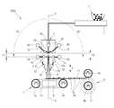
도 1은, 본 발명의 제1실시예에 따른 멜트블로운 섬유웹 제조장치의 개략 측면도,
도 2는, 본 발명의 제2실시예에 따른 멜트블로운 섬유웹 제조장치의 요부 개략측면도,
도 3은, 본 발명의 제3실시예에 따른 멜트블로운 섬유웹 제조장치의 요부 개략 측면도,
도 4는, 본 발명의 제4실시예에 따른 멜트블로운 섬유웹 제조장치의 요부 개략측면도,
도 5는, 본 발명의 제5실시예에 따른 멜트블로운 섬유웹 제조장치의 요부 개략측면도,
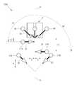
도 6는, 본 발명의 제6실시예에 따른 멜트블로운 섬유웹 제조장치의 요부 개략 측면도,
도 7은, 도 5 또는 도 6의 제조장치에 의해 제조된 멜트블로운 섬유웹의 개략 단면도,
도 8은, 본 발명의 제7실시예에 따른 멜트블로운 섬유웹 제조장치의 요부 개략 측면도,
도 9는, 본 발명의 제8실시예에 따른 멜트블로운 섬유웹 제조장치의 요부 확대 개략 측면도,
도 10은, 본 발명의 제9실시예에 따른 멜트블로운 섬유웹 제조장치의 개략 단면도,
도 11은, 본 발명에 따른 멜트블로운 섬유웹 제조방법의 순서도,
도 12는, 본 발명에 따른 멜트블로운 섬유웹의 효과를 시험하기 위해, 상기 멜트블로운 섬유웹을 제조하기 위해 구성된 제조장치의 개략단면도,
도 13은, 본 발명의 제1실시예 내지 제5실시예에 따른 멜트블로운 섬유웹과 비교예 2의 흡음능력을 실험한 결과 그래프,
도 14는, 본 발명의 제6실시예 내지 제10실시예에 따른 멜트블로운 섬유웹과 비교예 2의 흡음능력을 실험한 결과 그래프,
도 15는, 본 발명의 제11실시예 내지 제14실시예에 따른 멜트블로운 섬유웹과 비교예 2의 흡음능력을 실험한 결과 그래프이다.1 is a schematic side view of a meltblown fiber web manufacturing apparatus according to a first embodiment of the present invention;
2 is a schematic side view of a portion of a meltblown fiber web manufacturing apparatus according to a second embodiment of the present invention,
3 is a schematic side view of a portion of a meltblown fiber web manufacturing apparatus according to a third embodiment of the present invention,
4 is a schematic side view of a portion of a meltblown fiber web manufacturing apparatus according to a fourth embodiment of the present invention;
5 is a schematic side view of a portion of a meltblown fiber web manufacturing apparatus according to a fifth embodiment of the present invention;
6 is a schematic side view of a portion of a meltblown fiber web manufacturing apparatus according to a sixth embodiment of the present invention;
Fig. 7 is a schematic cross-sectional view of a meltblown fiber web produced by the manufacturing apparatus of Fig. 5 or Fig. 6,
8 is a schematic side view of a portion of a meltblown fiber web manufacturing apparatus according to a seventh embodiment of the present invention;
FIG. 9 is a schematic side elevational view of an essential portion of a meltblown fiber web manufacturing apparatus according to an eighth embodiment of the present invention,
10 is a schematic cross-sectional view of a meltblown fiber web manufacturing apparatus according to a ninth embodiment of the present invention,
11 is a flow chart of a method for producing a meltblown fiber web according to the present invention,
12 is a schematic cross-sectional view of a manufacturing apparatus configured to manufacture the meltblown fibrous web to test the effect of the meltblown fibrous web according to the present invention, Fig.
13 is a graph showing the results of experiments on the sound absorbing ability of the meltblown fiber web according to the first to fifth embodiments of the present invention and the comparative example 2,
FIG. 14 is a graph showing the results of tests on the sound absorbing ability of the meltblown fiber web according to the sixth to tenth embodiments of the present invention and the comparative example 2,
FIG. 15 is a graph showing the results of tests on the sound absorbing ability of the meltblown fiber web and the comparative example 2 according to the eleventh to fourteenth embodiments of the present invention.
이하, 첨부된 도면들을 참조하면서 본 발명의 바람직한 실시예에 따른 멜트블로운 섬유웹의 제조방법 및 그 제조장치를 상세히 설명하기로 한다.Hereinafter, a method for manufacturing a meltblown fiber web and an apparatus for manufacturing the same according to a preferred embodiment of the present invention will be described in detail with reference to the accompanying drawings.
본 명세서상에서 사용되는 용어 “폴리올레핀”은 탄소 및 수소 원자로만 이루어진 포화된 개방 사슬의 중합체 탄화수소 계열 중 임의의 것을 의미한다. 일반적인 폴리올레핀은 폴리에틸렌, 폴리프로필렌, 폴리메틸펜텐 및 에틸렌, 프로필렌 및 메틸펜텐 단량체의 다양한 배합물을 포함한다.As used herein, the term " polyolefin " refers to any of the saturated hydrocarbon chain hydrocarbon chains consisting solely of carbon and hydrogen atoms. Typical polyolefins include polyethylene, polypropylene, polymethylpentene and various combinations of ethylene, propylene and methylpentene monomers.
본 명세서상에서 사용되는 용어 “폴리프로필렌”(PP)은 프로필렌의 단독 중합체 뿐만 아니라, 반복단위 40% 이상의 프로필렌 단위인 공중합체도 포함한다.As used herein, the term " polypropylene " (PP) includes not only a homopolymer of propylene, but also a copolymer which is a propylene unit having a repeating unit of 40% or more.
본 명세서상에서 사용되는 용어 “폴리에스테르”는 에스테르 단위의 형성에 의해 연결되고 반복 단위 85% 이상이 디카르복실산과 디히드록시 알코올과의 축합 생성물인 중합체를 포함하는 개념이다. 이는 방향족, 지방족, 포화 및 불포화 이산 및 이알콜을 포함한다.As used herein, the term " polyester " is a concept that is linked by the formation of ester units, and wherein at least 85% of the repeat units are polymers that are condensation products of dicarboxylic acids with dihydroxy alcohols. These include aromatic, aliphatic, saturated and unsaturated diacids and these alcohols.
본 명세서상에서 사용되는 용어 “폴리에스테르”는 공중합체 및 블렌드 및 이들 변형물을 포함한다. 폴리에스테르의 일반적인 예는 에틸렌 글리콜과 테레프탈산과의 축합 생성물인 폴리에틸렌 테레프탈레이트(PET)이다.The term " polyester " as used herein includes copolymers and blends and modifications thereof. A typical example of the polyester is polyethylene terephthalate (PET) which is a condensation product of ethylene glycol and terephthalic acid.
본 명세서상에서 사용되는 용어 “멜트블로운 섬유”및 “멜트블로운 필라멘트”는 용융된 가공성 중합체를 다수의 미세한 모세관을 통해 고온 고속의 압축기체와 압출함으로써 형성된 섬유 또는 필라멘트를 의미한다.As used herein, the terms " meltblown fibers " and " meltblown filaments " refer to fibers or filaments formed by extruding molten, processable polymer through a plurality of fine capillaries with high temperature and high pressure compressed gas.
여기서, 상기 모세관은 원형, 삼각형 및 사각형을 포함하는 다각형, 별표모양 등 다양하게 변경될 수 있다. 또한, 일례로서, 고온 고속의 압축기체는 용융 열가소성 중합체 재료의 필라멘트를 가늘게 하여 직경을 약 0.5 내지 10㎛으로 감소시킬 수 있다. 멜트블로운 섬유는 불연속 섬유일수도 있고 연소 섬유일 수도 있다. 멜트블로운 필라멘트는 후술할 수집장치의 표면에 불규칙하게 퇴적됨으로써 임의로 분산된 섬유의 웹을 형성할 수 있다.Here, the capillary may be variously modified, such as a polygon including a circle, a triangle, and a square, an asterisk, and the like. In addition, by way of example, a high temperature, high speed compressed gas may reduce the diameter of the filament of the molten thermoplastic polymer material to about 0.5 to 10 mu m. The meltblown fibers may be discontinuous fibers or combustion fibers. The meltblown filaments are irregularly deposited on the surface of a collecting device to be described later, so that a randomly distributed fiber web can be formed.
본 명세서상에서 사용되는 용어 “스펀본드”섬유는 모세관을 통해 압출되는 다수의 미세한 직경의 필라멘트를 고온의 관을 이용해 연신시키는 방법으로 제조된 섬유웹을 의미한다.The term " spunbond " fiber, as used herein, refers to a fibrous web produced by a method of drawing a plurality of fine diameter filaments extruded through a capillary tube using a hot tube.
스펀본드 섬유는 필라멘트의 길이방향으로 연속적이고 상기 필라멘트의 평균 직경이 약 5㎛ 보다 크다. 스펀본드 부직물 또는 부직웹은 다공질 스크린 또는 벨트와 같은 수집 표면상에서 불규칙하게 스펀본드를 배치함으로써 형성된다.The spunbond fibers are continuous in the length direction of the filaments and the average diameter of the filaments is greater than about 5 占 퐉. The spunbond nonwoven web or nonwoven web is formed by irregularly arranging the spunbond on a collecting surface such as a porous screen or belt.
본 명세서에서 사용되는 “부직물, 섬유웹 및 부직웹”은 개별섬유, 필라멘트 또는 실이 편성물과 대조적으로 패턴 없이 불규칙한 방식으로 배치됨으로써 평면 물질을 형성하는, 개별섬유, 필라멘트 또는 실로 구성된 구조물을 의미한다.As used herein, " nonwoven, fibrous web and nonwoven web " means a structure composed of individual fibers, filaments, or yarns that form a planar material by disposing the individual fibers, filaments or yarns in an irregular manner in a pattern- do.
이하에서는 도면을 참조하여 본 발명에 따른 바람직한 실시예를 상세히 설명하기로 한다. Hereinafter, preferred embodiments of the present invention will be described in detail with reference to the drawings.
본 발명의 제1실시예에 따른 멜트블로운 섬유웹 제조장치(100)는, 도 1에 도시된 바와 같이, 열가소성 수지(1)를 가열하여 용융된 열가소성 수지를 압출하는 가열압출부(2); 상기 용융된 열가소성 수지를 필라멘트(6) 형태로 자중방향(A)을 따라 기체와 함께 분사하는 필라멘트 분사부(3)와; 상기 필라멘트(6)를 꼬도록 상기 분사되는 필라멘트(6)를 향해 상기 자중방향(A)에 대해 교차하는 방향으로 기체를 분사하는 교차방향 기체분사부(5A, 5B)와; 상기 교차방향 기체분사부(5A, 5B)를 경유한 상기 필라멘트(6)를 포집하여 섬유웹(11)을 형성하는 포집부(7)를 포함한다.1, an
여기서, 상기 필라멘트 분사부(3)는 자중방향(A)이 아닌 임의의 제1방향을 따라 필라멘트와 기체를 분사할 수도 있다.Here, the
상기 가열압출부(2)에 투입되는 열가소성 고분자 수지(1)는 폴리올레핀 또는 폴리에스테르 또는 그 외 공지된 열가소성 고분자 수지를 포함할 수 있다. 투입된 고분자 수지(1)는 상기 가열압출부(2)에 의해 가열되어 용융상태로 변환되어 압출된다.The thermoplastic polymer resin (1) to be fed into the hot extrusion part (2) may comprise polyolefin, polyester or other known thermoplastic polymer resin. The charged
또한, 상기 열가소성 고분자 수지(1)에는 상술한 폴리올레핀 또는 폴리에스테르 또는 그 외 공지된 열가소성 고분자 수지 외에 무기 및/또는 유기 첨가제가 첨가될 수 있다. 이러한 무기 및/또는 유기 첨가제가 첨가됨으로써 용융된 상태의 열가소성 고분자 수지의 방사 점도를 조절하거나 필라멘트의 물성 즉, 비중 및 경도를 조절할 수 있다. 또한, 상기 무기 및/또는 유기 첨가제가 첨가됨으로써 필터의 여과효율 및 내구성을 향상시킬 수도 있다. 이러한 첨가제의 종류 및 비율은 당업자에게 널리 알려져 있으므로 자세한 설명은 생략하기로 한다.In addition to the above-mentioned polyolefin or polyester or other known thermoplastic polymer resin, inorganic and / or organic additives may be added to the thermoplastic polymer resin (1). By adding such an inorganic and / or organic additive, the spinning viscosity of the thermoplastic polymer resin in a molten state can be controlled, or the physical properties of the filament, that is, specific gravity and hardness can be controlled. In addition, the filtering efficiency and durability of the filter may be improved by adding the inorganic and / or organic additives. The types and ratios of these additives are well known to those skilled in the art, and a detailed description thereof will be omitted.
상기 필라멘트 분사부(3)는 상기 가열압출부(2)로부터 공급되는 용융된 열가소성 고분자수지(1)가 유입되는 유입부(3B)와, 상기 유입부(3B)로부터 유입된 상기 용융된 열가소성 고분자수지(1)가 임시 저장되는 챔버(3C)와, 상기 챔버(3C)로부터 상기 포집부(7)를 향해 형성된 복수의 필라멘트 분사관(3A)를 포함한다.The
상기 복수의 필라멘트 분사관(3A)는 원통형, 삼각형 및 사각형을 포함하는 다각형, 별모양 등 다양한 형태로 마련될 수 있다.The plurality of
또한, 상기 필라멘트 분사관(3A)는 도 1에서는 1개인 것처럼 도시되어 있으나, 실제로는 도 1의 지면(紙面)에 대해 수직인 방향을 따라 복수개 배치된다.Although the
상기 챔버(3C)에 임시 저장된 용융된 열가소성 고분자수지(1)는 상기 필라멘트 분사부(3)를 통과하면서 필라멘트 형태로 변환되어 자중방향(A)으로 배출된다. 여기서, 상기 챔버(3C)는 미도시된 기어펌프에 의해 그 내부에 압력이 가해지며 상기 압력에 의해 상기 필라멘트가 분사된다. 물론, 상기 챔버(3C) 내부를 가압하기 위해 상술한 기어펌프 외에도, 유압펌프, 로터리펌프 등 다양한 가압수단이 채용될 수 있다.The molten
여기서, 상기 필라멘트 분사부(3)는 상기 필라멘트 분사관(3A)를 통해 유출되는 상기 필라멘트를 길이방향(자중방향(A))으로 신장시킬 수 있도록 상기 필라멘트를 향해 기체를 분사하는 하방 기체분사부(4A, 4B)를 포함한다.Here, the
상기 하방 기체분사부(4A, 4B)는 도 1에 도시된 바와 같이, 상기 필라멘트 분사관(3A)를 기준으로 좌우에 각각 대칭적으로 배치될 수도 있다.The downward
또한, 상기 하방기체분사부(4A, 4B)의 기체분사노즐(12, 13)은 자중방향(A)에 대해 경사지게 배치될 수 있다. 상기 기체분사노즐(12, 13)로부터 분사되는 기체의 분사방향의 합력이 상기 자중방향(A)에 대해 대체로 평행하도도록, 상기 기체분사노즐(12, 13)이 마련될 수 있다. 여기서, 상기 기체분사노즐(12, 13)이 상기 필라멘트 분사관(3A)의 길이방향을 기준으로 좌우 대칭으로 마련되는 경우, 상기 기체분사노즐(12, 13)로부터 분사되는 기체의 분사방향의 합력이 상기 자중방향(A)에 대체로 평행하게 될 것이다.Further, the
상기 하방 기체분사부(4A, 4B)는 상기 기체분사노즐(12, 13)을 통해 기체를 분사한다. 이에 따라, 상기 기체와의 충돌로 인해 상기 필라멘트 분사관(3A)를 통해 배출되는 필라멘트(6)가 그 길이방향으로 신장되게 되며 그 직경이 감소하게 된다.The downward
여기서, 상기 기체는 고온 및/또는 고속의 기체일 수 있다. 이에 의해, 고온 및/또는 고속의 기체인 경우, 필라멘트(6)의 직경을 더욱 더 감소시킬 수 있다.Here, the gas may be a gas at a high temperature and / or a high velocity. Thereby, in the case of a high-temperature and / or high-velocity gas, the diameter of the
여기서, 상기 기체는 대기 중의 공기일 수 있다. 물론, 상기 기체는 기체 상태의 질소, 산소, 수증기의 다양한 배합비로 구성된 기체일 수도 있고, 단일성분의 불활성기체만으로 이루어 질수도 있다. 상기 기체의 종류는 다양하게 변경될 수 있다.Here, the gas may be atmospheric air. Of course, the gas may be a gas composed of various amounts of nitrogen, oxygen, and water vapor in a gaseous state, or may be composed of only a single component of an inert gas. The type of the gas may be variously changed.
여기서, 고온이란 상온(25도씨)과 같거나 상온보다 높은 온도로서 상기 필라멘트(6)를 길이방향으로 신장시킬 수 있는 온도이면 충분하다. 이에, 상기 필레멘트 분사부(3)에 의해 분사되는 기체의 온도는 설계자의 선택에 의해 다양한 온도로 변경될 수 있다.Here, the high temperature is a temperature which is equal to or higher than room temperature (25 degrees Celsius) or is a temperature at which the
또한, 상기 고속이란 분사되는 기체가 소정 방향성을 가지고 분사될 수 있을 정도의 속력을 의미한다. 분사되는 기체의 속력도 상기 온도와 마찬가지로 설계자의 선택에 의해 다양한 값으로 변경될 수 있다.The term " high speed " as used herein means a speed at which the injected gas can be injected in a predetermined direction. The velocity of the injected gas can be changed to various values by the designer's choice like the above temperature.
한편, 상기 교차방향 기체분사부(5A, 5B)는 상기 필라멘트 분사부(3)를 통해 분사된 필라멘트(6)를 향해 상기 자중방향(A)에 대해 교차하는 방향으로 기체를 분사한다.The cross
상기 교차방향 기체분사부(5A, 5B)도 상기 필라멘트 분사부(3)처럼 도 1의 지면(紙面)에 수직한 방향으로 연장되어 지면에 수직한 방향으로의 소정폭 만큼 기체를 분사하도록 마련될 수 있다.The cross direction
여기서, 상기 교차방향 기체분사부(5A, 5B)의 지면(紙面)에 수직한 방향으로의 기체분사폭이 상기 필라멘트 분사부(3)에 의해 분사되는 필라멘트(6)의 지면방향으로의 폭보다 같거나 넓은 것이 바람직하다.The gas injection width in the direction perpendicular to the paper surface of the cross direction
여기서, 도 1에서는 상기 교차방향 기체분사부(5A, 5B)로 한 쌍(2개)를 도시하고 있으나, 경우에 따라서는 1개로 마련될 수도 있다.In FIG. 1, a pair (two) of the cross-directional
여기서, 상기 기체는 고온 및/또는 고속의 공기일 수 있다. 이에 따라, 고온 고속의 공기와 상기 분사되는 필라멘트(6)가 서로 충돌함에 따라 상기 필라멘트(6)의 직경은 1~60% 감소하고 그 길이는 1~60% 증가하며, 상기 필라멘트(6)의 표면적이 1~60%증가한다. 또한, 상기 필라멘트(6)는 상기 자중방향(A)을 중심으로 마치 코일 스프링 모양처럼 꼬이는 형태를 가지게 된다.Here, the gas may be high temperature and / or high velocity air. The diameter of the
여기서, 상기 기체의 성분 및 상기 기체에 포함된 기체의 종류는 다양하게 변경될 수 있음은 물론이다.Here, it goes without saying that the composition of the gas and the type of gas contained in the gas may be variously changed.
또한, 상기 교차방향 기체분사부(5A, 5B)와 상기 하방 기체분사부(4A, 4B)는 동일한 성분 및 종류의 기체를 분사할 수도 있다. 다만, 그 분사되는 기체의 압력과 온도는 달라질 수 있다.Further, the cross-direction
여기서, 상기 교차방향 기체분사부(5A, 5B)는 각각 상기 기체를 분사하기 위한 분사관(14, 15)를 갖는다. 상기 분사관(14, 15)는 노즐로서 마련될 수도 있다.Here, the intersecting direction
상기 교차방향 기체분사부(5A, 5B)는 상기 필라멘트 분사관(3A)의 단부에서 상기 각 교차방향 기체분사부(5A, 5B)의 분사관(14, 15)까지의 수직방향(자중방향, A)으로의 거리(H1, H2)가 서로 다른 것이 바람직하다. 왜냐하면, 각 분사관(14, 15)까지의 수직방향 거리(H1, H2)가 같은 경우, 분사된 기체가 서로 상쇄될 수 있기 때문이다.The cross direction
물론, 경우에 따라서, 가령 서로 수직방향 거리(H1, H2)가 같더라도 어느 한 기체분사부(5A, 5B)의 분사속도를 다른 한 기체분사부(5A, 5B)의 분사속도보다 크게 하는 경우에는 수직방향 거리(H1, H2)를 같게 하더라도 상기 필라멘트(6)의 꼬임정도, 길이 및 표면적을 증가시키고 직경을 감소시킬 수 있다.Of course, even if the vertical distances H1 and H2 are equal to each other, if the injection speed of one of the
여기서, 도 1에 도시된 좌측의 상기 교차방향 기체분사부(5A)는 상기 필라멘트 분사관(3A)의 길이방향의 연장선(B)을 기준으로 반시계방향으로 제1각도(θ1)만큼 기울어진 방향으로 상기 기체를 상기 필라멘트(6)를 향해 분사할 수 있다.Here, the intersecting direction
또한, 우측의 상기 교차방향 기체분사부(5B)는 상기 필라멘트 분사관(3A)의 길이방향의 연장선(B)을 기준으로 시계방향으로 제2각도(θ2)만큼 기울어진 방향으로 상기 기체를 상기 필라멘트(6)를 향해 분사할 수 있다.Further, the cross-directional
여기서, 상기 제1각도(θ1) 및 제2각도(θ2)는 90도 일 수 있다. 물론, 상기 제1각도(θ1) 및 제2각도(θ2)는 1도 이상 179도 이하 범위에서 임의의 각도 일 수 있다. 경우에 따라서, 상기 제1각도(θ1) 및 제2각도(θ2)는 서로 다를 수도 있다.Here, the first angle? 1 and the second angle? 2 may be 90 degrees. Of course, the first angle [theta] 1 and the second angle [theta] 2 may be any angle within the range of 1 degree to 179 degrees. In some cases, the first angle? 1 and the second angle? 2 may be different from each other.
상기 교차방향 기체분사부(5A, 5B)는 그 분사관(14, 15)의 단부로부터 상기 필라멘트 분사관(3A)의 길이방향 연장선(B)까지의 수평거리가 0.5~50cm, 바람직하게는 0.5~10cm 범위내로 배치될 수 있다. 물론, 이러한 배치는 일례에 불과하다.The cross direction
또한, 상기 교차방향 기체분사부(5A, 5B)는 그 분사관(14, 15)로부터 상기 필라멘트 분사관(3A)의 단부까지의 수직거리는 1~50cm, 바람직하게는 1~30cm로 배치될 수 있다. 물론, 이외에도 다양하게 수직거리가 변경될 수도 있다.The vertical distance from the
상기 교차방향 기체분사부(5A, 5B)는 상기 분사부(3)의 하방 기체분사부(4A, 4B)에 의해서도 어느 정도 상기 필라멘트(6)가 꼬일수 있으나 상기 교차방향 기체분사부(5A, 5B)가 상기 필라멘트(6)의 꼬임을 더욱 더 극대화 시킨다. 이에 따라, 상기 필라멘트(6)의 직경을 더욱 감소시킬 수 있으며 그 길이도 신장시킬 수 있다. 상기 필라멘트(6)가 더욱 꼬아진 형태로 만들어짐에 따라 이러한 필라멘트(6)의 적층물인 섬유웹은 그 벌키(bulky)성이 크게 개선될 수 있다.The cross-directional
여기서, 벌키(bulky)성은 무게에 비하여 부피가 큰 것을 의미하며, 그로인해 보다 가벼운 섬유웹을 제조할 수 있다.Here, the bulky property means that the bulkiness is larger than the weight, and thereby a lighter fiber web can be produced.
상기 교차방향 기체분사부(5A, 5B)의 기능에 대해서 보다 상세하게 설명하면 다음과 같다.The functions of the cross-directional
상기 필라멘트 분사부(3)에서 상기 포집부(7)로 분사되는 필라멘트(6)는 상기 필라멘트 분사부(3)와 상기 포집부(7) 사이의 상온의 공기와 접촉하면 급속히 표면이 냉각된다. 이로 인해 상기 필라멘트(6)가 경화되어 직경, 길이, 표면적과 같은 그 외형이 변형이 거의 불가능하게 된다.The
따라서, 상기 필라멘트 분사부(3)로부터 분사된 필라멘트가 변형 불가능한 온도 이하로 떨어지기 전에 상기 필라멘트(6)에 고온 및/또는 고속의 기체를 상기 교차방향으로 분사하여 상기 필라멘트(6)와 충돌시키면 열에너지와 충돌에너지가 필라멘트에 전달되어 상기 필라멘트(6)의 직경이 보다 가늘어 질 뿐만 아니라 더욱 꼬아진 형태를 띄게 된다.Therefore, before the filament injected from the
여기서, 상기 교차방향 기체분사부(5A, 5B)에서 분사되는 기체속도는 상기 필라멘트 분사부(3)의 상기 하방향 기체분사부(4A, 4B)에서 분사되는 기체속도의 5~90% 범위에 있는 것이 바람직하다. 왜냐하면, 상기 교차방향 기체분사부(5A, 5B)에 의해 분사되는 횡방향 기체속도가 상기 하방향 기체분사부(4A, 4B)에 의해 분사되는 종방향 기체속도와 비슷하거나 그 보다 클 경우(90%초과), 상기 필라멘트 분사부(3)에서 상기 포집부(7)까지의 기체유동이 유지되기가 곤란하기 때문이다. 또한, 교차방향 기체분사부(5A, 5B)에 의해 분사되는 횡방향 기체속도가 상기 하방향 기체분사부(4A, 4B)에 의해 분사되는 종방향 기체속도 대비 너무 작을 경우(5%미만) 상기 필라멘트(6)의 표면을 개질할 만한 충분한 충격에너지를 전달할 수 없기 때문이다.The gas velocity injected from the cross direction
상기 교차방향 기체분사부(5A, 5B)에서 분사하는 기체 온도는, 동일한 속도 조건 하에서 상기 필라멘트 분사부(3)로부터의 거리(길이방향의 연장선(B) 방향으로의 거리)가 멀수록 높은 것이 바람직하다. 왜냐하면, 상술한 바와 같이, 상기 필라멘트 분사부(3)로부터 멀리 떨어진 위치의 필라멘트는 외부공기와 접촉되어 더 많이 냉각되므로 필라멘트(6)의 외형을 변형시키기 위해서는 보다 큰 열에너지가 필요하기 때문이다.The gas temperature injected from the cross direction
여기서, 상기 교차방향 기체분사부(5A, 5B)에 의해 분사된 기체 스트림을 맞은 필라멘트(6)는 상기 포집부(7)에 일정한 중량으로 수집된다. 이때, 상기 포집부(7)의 하부에는 후술할 기체흡입부(8)가 배치될 수 있다. 이에 의해, 상기 교차방향 기체분사부(5A, 5B)에 의해 교차방향으로 기체가 분사되더라도 상기 필라멘트 분사부(3)로부터 상기 기체흡입부(8)까지로 이어지는 일정한 공기유동이 형성되게 된다. 이로 인해, 필라멘트(6)의 이송경로가 대체로 일정하게 된다.Here, the
한편, 상기 포집부(7)는 상기 교차방향 기체분사부(5A, 5B)를 경유한 상기 필라멘트(6)가 적층되는 벨트(7c) 및 상기 벨트(7c)를 구동하는 한 쌍의 롤러(7a, 7b)를 포함한다.On the other hand, the collecting
경우에 따라서, 상기 포집부(7)는 회전하는 원통형 드럼으로 마련될 수도 있다.In some cases, the collecting
또한, 본 발명에 따른 멜트블로운 섬유웹 제조장치(100)는, 상기 분사부(3)에서 분출되는 필라멘트의 이송방향이 일정하도록 상기 필라멘트 분사부(3)의 하부에 배치된 기체흡입부(8)를 더 포함할 수 있다.The apparatus for manufacturing a
기체흡입부(8)는 상기 분사부(3)의 상기 하방향 기체분사유닛(4A, 4B)으로부터 분사된 기체를 흡입한다. 이에 따라, 상기 분사되는 고속기체의 흐름으로 인해 이송되는 상기 필라멘트의 이송방향, 즉 분사방향도 대체로 일정하게 유지될 수 있다. 여기서, 상기 필라멘트의 분사방향은 대체로 필라멘트 분사부(3)의 상기 필라멘트 분사관(3A)의 길이방향 연장선(B)과 대체로 나란하다.The
여기서, 상기 필라멘트 분사관(3A)은 그 길이방향이 대체로 자중방향(A)이 되도록 배치될 수 있다. 또한, 상기 필라멘트 분사부(3)에 의해서 분사되는 필라멘트(6)의 분사방향은 자중방향(A)일 수 있다.Here, the
하지만, 상기 필라멘트 분사관(3A)의 길이방향을 자중방향으로 하지 않는 경우와 같이, 필요에 따라서, 상기 필라멘트(6)의 분사방향이 자중방향(A)이 아닐 수도 있다.However, the filing direction of the
여기서, 상기 필라멘트 분사부(3)에 의해서 분사되는 필라멘트(6)의 분사방향은 제1방향으로 호칭될 수도 있다.Here, the injection direction of the
또한, 본 발명에 따른 멜트블로운 섬유웹 제조장치(100)는, 상기 포집부(7)에 의해 수집된 섬유웹을 권취하는 권취부(9)를 더 포함할 수 있다.The
상기 권취부(9)는 서로 대향하여 회전하는 한 쌍의 롤러(9a, 9b)로 마련될 수 있다. 상기 한 쌍의 롤러(9a, 9b) 중 어느 하나가 상기 포집부(7)의 벨트(7c)에 포집된 섬유웹(11)을 이송받아 그 외면에 상기 섬유웹(11)을 권취할 수 있다.The winding
상기 권취부(9)는 일례에 불과하고 다양하게 변경될 수 있으며, 경우에 따라서는 생략될 수도 있다.The winding
이상에서 설명한 바와 같이, 본 발명에 따른 멜트블로운 섬유웹 제조장치(100)로 섬유웹을 제조하는 경우, 필라멘트(6) 각각의 벌키(bulky) 특성을 향상시킬 수 있다. 다시 말해, 각 필라멘트(6)의 표면적을 보다 넓게 하고 각 필라멘트(6)의 길이를 길게하는 동시에 그 직경을 감소시킬 수 있다. 성질이 변형된 필라멘트(6)를 적층함으로써 형성된 섬유웹 또한 벌키(bulky)특성이 우수하다. 다시 말해서, 섬유웹이 부피 및 표면적은 크지만 그 무게는 가볍다.As described above, when the fiber web is manufactured by the meltblown fiber
이는, 필라멘트의 단위 면적당 표면적이 증가하고 단위면적당 중량이 감소함을 의미한다. 이와 같은 특성으로 인해 흡음성, 단열성, 흡습성, 흡유성 및 세척력이 우수한 섬유웹을 제조할 수 있다.This means that the surface area per unit area of the filament increases and the weight per unit area decreases. Due to such characteristics, it is possible to produce a fibrous web excellent in sound absorption, heat insulation, hygroscopicity, absorbency and cleaning ability.
여기서, 위의 제조장치(100)로 제조된 멜트블로운 섬유웹(11)의 양면 또는 어느 일면에는 강성이 상대적으로 큰 스펀본드 웹(미도시)이 고온 롤 캘링더링과 같은 공지된 방법에 의해서 결합될 수 있다. 경우에 따라서는, 포화증기챔버를 이용하여 스펀본드 웹이 상기 멜트블로운 섬유웹(11)에 결합될 수 있다.Here, a spunbond web (not shown) having a relatively high rigidity is formed on both sides or on one side of the
한편, 본 발명의 제2실시예에 따른 멜트블로운 섬유웹 제조장치(100a)는, 도 2에 도시된 바와 같이, 상술한 제1실시예와 비교하여 교차방향 기체분사부(21A, 21B)가 상이하며, 나머지 구성은 동일하다.2, the
제1실시예의 교차방향 기체분사부(5A, 5B)에 비해 제2실시예의 교차방향 기체분사부(21A, 21B)가 상기 필라멘트 분사관(3A)의 길이방향 연장선(B) 방향으로 서로 더 멀리 이격되어 있다.The cross direction
제2실시예의 교차방향 기체분사부(21A, 21B)는 상기 필라멘트 분사부(3)로부터 상기 필라멘트 분사관(3A)의 길이방향 연장선(B) 방향으로 제1거리만큼 떨어진 제1교차방향 기체분사부(21A)와 상기 길이방향 연장선(B) 방향으로 제1거리와는 다른 제2거리만큼 떨어진 제2교차방향 기체분사부(21B)를 포함한다.The cross direction
또한, 상기 교차방향 기체분사부(21A, 21B)는 상기 길이방향 연장선(B)을 기준으로 서로 대향하도록 배치된다. 즉, 상기 교차방향 기체분사부(21A, 21B)의 기체분사방향이 서로 반대가 되도록 배치된다.Further, the cross-directional
상기 제1교차방향 기체분사부(21A)는 상기 길이방향 연장선(B)을 기준으로 반시계방향으로 제1각도(θ1) 경사진 방향으로 기체를 분사하는 제1분사관(22)를 포함한다.The first cross-directional
상기 제2교차방향 기체분사부(21B)는 상기 길이방향 연장선(B)을 기준으로 시계방향으로 제2각도(θ2) 경사진 방향으로 기체를 분사하는 제2분사관(23)를 포함한다.The second cross-directional
여기서, 상기 제1각도(θ1) 및 상기 제2각도(θ2)는 같을 수 있고, 경우에 따라서는 다를 수도 있다.Here, the first angle [theta] 1 and the second angle [theta] 2 may be the same, and may be different depending on the case.
한편, 본 발명의 제3실시예에 따른 멜트블로운 섬유웹 제조장치(100b)는, 도 3에 도시된 바와 같이, 상술한 제1실시예와 비교하여 상이한 교차방향 기체분사부(50A, 50B)를 포함한다. 나머지 구성은 동일하므로 설명의 편의상 생략하기로 한다.3, the meltblown fiber
제3실시예의 교차방향 기체분사부(50A, 50B)는 상기 필라멘트 분사부(3)의 상기 필라멘트 분사관(3A)의 길이방향 연장선(B) 방향을 따라 2개의 교차방향 기체분사부(50A, 50B)가 나란히 배치된다.The cross direction
보다 상세하게 설명하면, 상기 길이방향 연장선(B) 방향을 따라 2개의 교차방향 기체분사부(50A, 50B)가 상기 필라멘트 분사부(3)로부터의 서로 다른 거리만큼 떨어져서 배치된다.More specifically, two cross-directional
상기 길이방향 연장선(B)과 상기 각 교차방향 기체분사부(50A, 50B)에서의 기체분사방향이 이루는 각도는 다양하게 변경될 수 있다.The angle formed by the longitudinal extension line B and the gas injection direction in each of the cross direction
한편, 본 발명의 제4실시예에 따른 멜트블로운 섬유웹 제조장치(100c)도 제1실시예와 비교하여 도 4에 도시된 바와 같이, 상술한 제1실시예와 비교하여 상이한 교차방향 기체분사부(500A, 500B)를 포함한다.4, the meltblown fiber
제4실시예의 교차방향 기체분사부(500A, 500B, 500C)는, 총 3개의 교차방향 기체분사부(500A, 500B, 500C)를 포함한다.The cross direction
상기 필라멘트 분사관(3A)의 길이방향 연장선(B)을 기준으로 일측에 2개의 교차방향 기체분사부(500A, 500C)가 배치되고 타측에 나머지 1개의 교차방향 기체분사부(500B)가 배치된다.Two crossing direction
각 교차방향 기체분사부(500A, 500B, 500C)에서 분사되는 기체방향과 상기 길이방향 연장선(B)이 이루는 각도는 다양하게 변경될 수 있다. 다시 말해, 상기 각 교차방향 기체분사부(500A, 500B, 500C)는 각각 상기 길이방향 연장선(B)에 대해 다양한 각도로 상기 필라멘트 분사부(3)에 의해 분사된 필라멘트(6)를 향해 기체를 분사할 수 있다.The angle between the gas direction injected from each of the
또한, 각 교차방향 기체분사부(500A, 500B, 500C)에서 분사하는 기체가 서로 상쇄되지 않도록, 상기 필라멘트 분사관(3A)의 단부로부터 각 교차방향 기체분사부(500A, 500B, 500C)까지의 상기 길이방향 연장선(B) 방향으로의 거리가 서로 다른 것이 바람직하다.In order to prevent the gases injected from the respective crosswise direction
이상에서 설명한 제2 내지 제4실시예의 교차방향 기체분사부(21A, 21B, 50A, 50B, 500A, 500B, 500C)는 일례에 불과하고 다양한 형태로 변경될 수 있다.The cross-directional
보다 상세하게 설명하면, 교차방향 기체분사부에 포함되는 기체분사부의 개수, 교차방향 기체분사부의 기체분사각도, 교차방향 기체분사부의 상기 필라멘트 분사부(3)로부터의 수직방향(자중방향)거리 또는 수평방향 거리, 분사될 기체의 압력 및 온도 등의 인자 중 적어도 어느 하나를 변경함으로써 필라멘트(6)의 직경, 표면적 및 꼬임정도를 임의로 변경할 수 있다.More specifically, the number of gas injecting portions included in the cross-direction gas injecting portion, the gas injecting angle of the cross-direction gas injecting portion, the vertical direction (self-weighting direction) distance from the
실험조건을 다양하게 변경하면서 본 발명의 실시예에 따라 제조된 섬유웹의 특성 및 흡음성능을 실험하였으며, 측정된 실험결과는 다음과 같다.The characteristics and the sound absorption performance of the fiber web produced according to the embodiment of the present invention were experimentally varied while varying experimental conditions. The experimental results are as follows.
필라멘트의 직경은 테스트 시편 섬유웹에서 대략 10개의 필라멘트를 임의로 추출하여 각 필라멘트를 광학현미경(SEM)으로 측정한 후 그 평균값을 마이크로미터(㎛)단위를 사용하여 표기 하였다. 시편의 중량은 단위 면적당 중량의 측정값이며 300 x 300 mm의 샘플을 임의의 위치에서 3매 취하여 중량 측정 후 1㎡의 중량으로 환산하여 평균치로 나타냈으며 시편의 두께는 100 x 100 mm의 샘플 3매를 수평의 시편 지지대에 놓고 버니아 캘리퍼스로 두께를 측정하여 평균치로 계산하였다. 또한 섬유웹의 흡음성능 시험은 MS 200-39에 준하여 간이간향실법(ALPHA CABIN)을 통해 측정하였다. 단 각각의 시편은 대기압외의 별도의 압력을 가하지 않은 상태에서 실험하였다.
The diameter of the filament was determined by randomly extracting about 10 filaments from the test piece fiber web, measuring each filament with an optical microscope (SEM), and expressing the average value in units of micrometers (탆). The weight of the specimen is a measurement of the weight per unit area, and three samples of 300 x 300 mm are taken at arbitrary positions, and the weight of the specimen is converted into a weight of 1
[실험조건 1][Experimental Condition 1]
도 1에 따른 제1실시예와 같은 제조장치(100)를 구성하며, 구성된 제조장치(100)의 세부구성은 다음과 같다.The detailed configuration of the
상기 지면(紙面)방향을 따라 배치된 복수의 상기 필라멘트 분사관(3A) 각각의 직경은 0.38mm이고, 그 개수는 32개/inch이다. MI(Melt Index) 1300g/10분인 폴리매래사의 호모폴리프로필렌인 HP461Y 그래이드를 사용하여 테스트하였다. 중합체는 열화를 막기 위해 열안정제와 산화방지제를 각각 0.2wt% 첨가하여 안정적인 필라멘트 분사를 유도하였다. 테스트 수행 전 상기 중합체를 100℃의 온도에서 건조하여 수분함량이 50ppm 미만이 되도록 하였다.Each of the plurality of
또한, 필라멘트 분사부(3)를 240℃로 가열하고 필라멘트 분사부(3)의 내부의 하방향 기체분사부(4A, 4B)에서 분사될 기체 온도와 속도을 각각 245 및 35m/sec의 조건으로 하였다. 또한, 상기 필라멘트 분사관(3)의 개구로부터 10mm 하방에 설치된 두 개의 기체분사노즐(12, 13)의 상기 지면(紙面)방향으로의 길이는 대략 89inch로 필라멘트 분사부(3)의 상기 지면(紙面)방향으로의 길이와 동일하게 설정하였다.The
상기 두 개의 기체분사노즐(12, 13)은 상기 분사관(3)의 길이방향 연장선(B)을 기준으로 각각 좌우에 40도의 각도로 배열하였으며 상기 두 개의 기체분사노즐(12, 13)간의 각도는 100도로 설정되었다.The two
상기 필라멘트 분사부(3)와 상기 포집부(7)간의 자중방향(A)의 거리는 85cm, 상기 필라멘트 분사부(3)와 제1교차방향 기체분사부(5A)의 분사관(14)까지의 자중방향(A)거리는 10cm, 상기 제1교차방향 기체분사부(5A)와 상기 제2교차방향 기체분사부(5B)간의 자중방향(A) 거리는 3cm, 상기 각 교차방향 기체분사부(5A, 5B)로부터 필라멘트 분사관(3A)의 길이방향 연장선(B)간의 거리(도 2의 D)는 2cm, 상기 제1각도(θ1) 및 제2각도(θ2)는 90도로 세팅하였다.The distance between the
또한, 상기 교차방향 기체분사부(5A, 5B)의 각 분사관의 상기 자중방향(A)의 가로방향으로의 길이는 2cm, 상기 교차방향 기체분사부(5A, 5B)의 상기 지면(紙面)방향으로의 길이도 89inch로 동일하게 하였다.The length in the transverse direction of the self-weighting direction A of each of the injection tubes of the cross-directional
상기 교차방향 기체분사부(5A, 5B)로부터 분사되는 기체 속도는 17.5m/sec, 기체의 온도는 160도씨로 하였다. 상기 필라멘트 분사부(3)에서 분사된 필라멘트(6)는 3.2m/min의 속도로 권취부(9) 방향으로 회전하는 포집부(7)에 필라멘트(6)를 적층하여 200g/㎡의 섬유웹을 형성시켜 권취하였다.
The gas velocity injected from the cross direction
[실험조건 2][Experimental Condition 2]
상술한 실험조건 1과 비교하여 상기 교차방향 기체분사부(5A, 5B)의 속도 및 온도조건만 조정하여 멜트블로운 섬유웹을 제조하였다. 상기 교차방향 기체분사부(5A, 5B)에서 분사되는 기체의 속도는 21m/sec, 기체온도는 180도씨로 하였다.
A meltblown fiber web was prepared by adjusting only the speed and temperature conditions of the cross direction
[실험조건 3][Experimental Condition 3]
실험조건 1과 비교하여 동일한 방사조건에서 도 1의 교차방향 기체분사부(5A, 5B)의 기체분사각도와 상기 필라멘트 분사관(3A)의 길이방향 연장선(B)가 이루는 각도(θ1, θ2)을 모두 170도로 조정하여 멜트블로운 섬유웹을 제조하였다.1 and 2 formed by the gas injection angle of the
여기서, 각도를 170도로 하면 교차방향 기체분사부(5A, 5B)의 각각에서 분사되는 기체방향은 상기 필라멘트 분사부(3)로부터 분사되는 필라멘트(6)의 하강을 저지하는 상방향으로 기체를 분사하게 된다. 이 경우, 교차방향 기체분사부(5A, 5B)의 기체분사속도가 상기 필라멘트 분사부(3), 정확하게는 하방향 기체분사부(4A, 4B)에 의해 분사되는 기체분사속도보다 작기 때문에 필라멘트(6)가 포집부(7) 방향으로 이동하는 데에는 영향을 주지 않는다.Here, when the angle is 170 degrees, the direction of the gas injected from each of the cross-direction
[실험조건 4][Experimental Condition 4]
실험조건 1과 비교하여 동일한 방사조건에서 도 1의 교차방향 기체분사부(5A, 5B)의 기체분사각도와 상기 필라멘트 분사관(3A)의 길이방향 연장선(B)가 이루는 각도(θ1, θ2)만을 모두 130도로 조정하여 멜트블로운 섬유웹을 제조하였다.1 and 2 formed by the gas injection angle of the
[실험조건 5][Experimental Condition 5]
실험조건 1과 비교하여 동일한 방사조건에서도 1의 교차방향 기체분사부(5A, 5B)의 기체분사각도와 상기 필라멘트 분사관(3A)의 길이방향 연장선(B)이 이루는 각도(θ1, θ2)만을 모두 50도로 조정하여 멜트블로운 섬유웹을 제조하였다.(1) and (2) formed by the gas injection angle of the cross-direction gas ejecting portions (5A, 5B) of 1 and the longitudinal extension line (B) of the filament injecting tube (3A) The meltblown fibrous webs were prepared at all 50 degrees.
[실험조건 6][Experimental Condition 6]
실험조건 1과 비교하여 동일한 방사조건에서 도 1의 교차방향 기체분사부(5A, 5B)의 기체분사각도와 상기 필라멘트 분사관(3A)의 길이방향 연장선(B)이 이루는 각도(θ1, θ2)만을 모두 10도로 조정하여 멜트블로운 섬유웹을 제조하였다.1 and 2 formed by the gas injection angle of the
[실험조건 7][Experimental Condition 7]
도 3에 도시된 제2실시예의 제조장치를 이용하여 테스트한 것이다.And tested using the manufacturing apparatus of the second embodiment shown in Fig.
상기 필라멘트 분사부(3)와 상기 포집부(7)간의 자중방향(A)의 거리는 85cm, 상기 필라멘트 분사부(3)와 제1교차방향 기체분사부(50A)의 분사관(51)까지의 자중방향(A)거리는 2cm, 상기 제1교차방향 기체분사부(50A)와 상기 제2교차방향 기체분사부(50B)간의 자중방향(A) 거리는 15cm, 상기 길이방향 연장선(B)에 대한 각 교차방향 기체분사부(50A, 50B)의 분사각도(θ1, θ2)는 모두 90도로 세팅하였다. 각 교차방향 기체분사부(50A, 50B)에서 분사된는 공기속도는 17.5m/sec, 공기온도는 160도씨로 하였다. 나머지 조건은 실험조건 1과 동일하다.The distance between the
[실험조건 8][Experimental Condition 8]
도 4에 도시된 바와 같이, 3개의 교차방향 기체분사부(500A, 500B, 500C)를 배치하여 테스트를 수행하였다.As shown in FIG. 4, three cross-directional
상기 필라멘트 분사부(3)와 상기 포집부(7)간의 자중방향(A)의 거리는 85cm, 상기 필라멘트 분사부(3)로부터 제1교차방향 기체분사부(500A)의 분사관(501)까지의 자중방향(A)거리는 10cm, 상기 제1교차방향 기체분사부(500A)와 상기 제2교차방향 기체분사부(500B)간의 자중방향(A) 거리는 3cm, 상기 제2교차방향 기체분사부(500B)와 상기 제3교차방향 기체분사부(500C)간의 자중방향(A) 거리는 3cm, 상기 길이방향 연장선(B)에 대한 각 교차방향 기체분사부(500A, 500B, 500C)의 분사각도는 모두 90도로 세팅하였다. 각 교차방향 기체분사부(50A, 50B)에서 분사된는 공기속도는 17.5m/sec, 공기온도는 160도씨로 하였다. 나머지 조건은 실험조건 1과 동일하다.The distance between the
[실험조건 9][Experimental Condition 9]
실험조건 1과 비교하여 동일한 방사조건에서 도 1의 교차방향 기체분사부(5A, 5B)의 분사되는 기체속도는 1.8m/sec, 기체의 온도는 25도씨로 조정하여 멜트블로운 섬유웹을 제조하였다. 나머지 조건은 실험조건 1과 동일하다.In comparison with
[비교예 1][Comparative Example 1]
실험조건 1과 동일한 조건 하에서 교차방향 기체분사부(5A, 5B)만을 제거한 후 포집부(7)에 필라멘트를 적층하여 200g/㎡의 섬유웹을 형성시켜 권취하였다.Only the cross
이상의 실험조건에 따른 실험결과는 다음과 같다.The experimental results according to the above experimental conditions are as follows.
[표 1][Table 1]

[표 2] 흡음성능 평가 결과[Table 2] Sound absorption performance evaluation result

[표 1]은 실험조건 1 내지 실험조건 9와 비교예 1의 조건에 의해 제조된 섬유웹의 질량 및 부피, 필라멘트의 직경을 측정한 것이다. 실험조건 1내지 9와 비교예 1 결과물의 필라멘트 직경과 섬유웹 부피를 비교해 보면, 본 발명의 교차방향 기체분사부의 사용으로 인한 효과를 분명히 확인 할 수 있다.[Table 1] shows the mass and the volume of the fiber web prepared according to the conditions of
교차방향 기체분사부의 사용으로 필라멘트의 직경은 비교예 1 대비 약 20~70% 줄어들 반면 최종 섬유웹의 두께는 최대 600%가량 증가하였다. 이는 필라멘트의 직경이 감소함과 더불어 필라멘트가 보다 꼬여진 무정형(無定形) 형태로의 변환됨에 따라 나타난 결과로 판단된다.The use of the cross-directional gas injection part reduced the diameter of the filament by about 20 to 70% compared to the comparative example 1, while the thickness of the final fiber web increased by up to 600%. This is because the diameter of the filament decreases and the filament is transformed into a more twisted amorphous form.
또한, 실험조건 1,2,9의 실험 결과로 보건데, 교차방향 기체 분사부를 동일하게 배치한 상태에서, 교차방향으로 분사되는 기체의 속도와 압력을 올리면 필라멘트의 직경이 감소하고 섬유웹의 부피가 증가하지만 반대로 기체의 온도와 압력을 내리면 필라멘트의 직경이 증가하고 섬유웹의 부피가 감소하는 것을 확인 할 수 있다.As a result of the
실험조건 3 내지 6은 동일한 제1실시예에서, 단지 교차방향 기체분사부에서 분사되는 기체분사방향의 각도(기체분사각)를 변경함에 따른 필라멘트의 직경과 섬유웹의 변화를 측정한 것이다.
다른 모든 조건이 동일한 상태에서도 기체분사각(θ1, θ2)만을 변경하기만 하면 개발자가 원하는 스펙의 최종 제품을 개발할 수 있음을 알 수 있다. 여기서, 교차방향의 기체분사각(θ1, θ2)이 90도로부터 멀어질수록, 즉, 보다 자중방향에 근접할수록 필라멘트의 직경은 작아지며 섬유웹의 부피가 증가하는 규칙성을 보여준다.It can be seen that the developer can develop the final product of the desired specification only by changing only the gas spray angles (? 1,? 2) under all other conditions. Here, the diameters of the filaments become smaller as the gas injection angles (? 1,? 2) in the cross direction are further away from 90 degrees, that is, closer to the self-weight direction, and the volume of the fibrous web is regularly increased.
이는 교차방향의 기체분사각(θ1, θ2)이 자중방향(A)에 근접할수록 필라멘트 분사관(3)에서 방출된 필라멘트(6)와 보다 짧은 시간에, 다시 말하면 필라멘트가 자체 열에너지를 덜 잃은 상태에서 교차방향 기체 스트림과 충돌하기 때문에 유발되는 효과로 판단된다.This is because the closer the gas spray angles? 1 and? 2 in the cross direction to the self-weight direction A, the shorter the
실험조건 8에서 가장 양호한 결과를 얻을 수 있었는데 이로부터 필라멘트에 가해지는 기체 스트림의 온도, 속도와 더불어 기체 스트림의 양도 필라멘트를 개질하는데 중요한 인자임을 보여준다.The most favorable results were obtained under
여기서, 본 발명에 따른 멀티블로운 섬유웹 제조장치를 사용하게 되면 밀도가 50kg/㎥ 미만의 벌키(bulky)성이 큰 멜트블로운 섬유웹(11)을 제조할 수 있음을 아울러 알 수 있다.Here, it can be seen that the
한편, 표 2는 실험조건 1 내지 9와 비교예 1의 실험조건 하에서 제조된 섬유웹의 흡음성능을 측정한 것으로 데이터는 재료의 흡음율을 나타낸다. 표 2에서 주파수(Hz)를 가로축으로 하여 각 실험조건에 따라 측정된 흡음성능 데이터를 표시한 것이다. 수치(흡음률)가 클수록 흡음성능이 큰 것을 의미한다. 표 2에서 "조건 1(2, 3, ... , 9)"는 표 1의 “실험조건 1(2, 3, ..., 9)”에 각각 대응한다.On the other hand, Table 2 shows the sound absorption performance of the fiber web produced under the
섬유웹의 흡음성능은 필라멘트의 직경이 작아질수록, 섬유웹의 부피가 커질수록 결과가 보다 양호했다. 실험조건 1내지 8은 고르게 뛰어난 흡음 성능을 가진 것으로 평가 됐으며, 실험조건 9와 비교예 1 경우 동일한 200g의 중량임에도 불구하고 재료의 흡음률이 매우 떨어지는 것으로 측정되었다. 즉, 비교예 1 대비 본 발명에 따른 실험조건 1 내지 9에서, 흡음성능이 주파수에 따라 적게는 1.5배에서 크게는 3.5배까지 향상된 것으로 측정되었다.The sound absorption performance of the fiber web was better as the diameter of the filament became smaller and the volume of the fibrous web became larger.
따라서, 본 발명의 멜트블로운 섬유웹 제조장치를 이용하면 기존제품에 비해 벌키(bulky)특성이 우수하고 흡음능력이 뛰어난 소재를 생산 할 수 있음을 알 수 있다.Therefore, it can be seen that when the meltblown fiber web manufacturing apparatus of the present invention is used, it is possible to produce a material excellent in bulky characteristics and excellent in sound absorption ability as compared with conventional products.
한편, 본 발명의 제5실시예에 따른 멜트블로운 섬유웹 제조장치(100g)는 도 5에 도시된 바와 같이, 열가소성 수지(1)를 가열하여 용융된 열가소성 수지를 압출하는 가열압출부(2); 상기 용융된 열가소성 수지를 필라멘트(6) 형태로 제1방향(A)을 따라 기체와 함께 분사하는 필라멘트 분사부(3)와; 상기 필라멘트 분사부(3)에 의해 분사되는 필라멘트(6)를 향해 폼 파티클(foam particle, 34)을 스캐터링하여 투입하는 파티클 스캐터링부(31)와; 상기 필라멘트(6) 및 상기 파티클(34)을 포집하여 섬유웹을 형성하는 포집부(7)를 포함한다.5, the
여기서, 상기 필라멘트(6)의 직경은 0.5~30㎛(마이크로미터)일 수 있다.Here, the diameter of the
여기서, 파티클 투입부(31)는 도 5에 도시된 바와 같이, 분사되는 필라멘트(6)를 향해 폼 파티클을 투입하도록 마련될 수 있다. 경우에 따라서, 상기 파티클 투입부(31)는 도면에 도시된 것과 달리, 상기 포집부(7)를 향해 상기 폼 파티클을 투입하도록 마련될 수도 있다. 즉, 상기 섬유웹이 권취되기 전에 상기 폼 파티클을 투입할 수 있는 한, 다양한 형태로 변경될 수 있다.Here, as shown in FIG. 5, the
여기서, 상기 제1실시예의 멜트블로운 섬유웹 제조장치(100)와 비교하여, 파티클 스캐터링부(31)가 더 추가된다.Here, as compared with the meltblown fiber
상기 파티클 스캐터링부(31)는, 도 5에 도시된 바와 같이, 상기 필라멘트 분사관(3A)의 연장선(B)에 대해서 일측에 될 수 있다. 물론, 경우에 따라서, 양측에 각각 배치될 수도 있다.The
상기 파티클 스캐터링부(31)는, 도 5에 도시된 바와 같이, 상기 필라멘트(6)가 분사되는 ??향으로 노출된 파티클 배출구(311a)를 구비한 파티클 이송관(311)과; 상기 파티클 이송관(311)으로 폼 파티클(foam particle)을 공급하는 파티클 공급부(312)와; 상기 파티클 이송관(311)에 진동을 가하는 액츄에이터(313)를 포함한다.As shown in FIG. 5, the
상기 파티클 이송관(311)은 상기 액츄에이터(313)로부터 가해지는 진동을 흡수할 수 있도록 연질 프라스틱 또는 아코디언 구조의 튜브로 마련될 수 있다.The
상기 파티클 공급부(312)는 폼 파티클을 공압에 의해 상기 파티클 이송관(311)으로 이송한다. 물론, 경우에 따라서, 상기 파티클 공급부(312)는 컨베이어 벨트와 같은 이송수단을 통해서 상기 파티클 이송관(311)으로 파티클을 이송할 수도 있다.The
상기 액츄에이터(313)는 회전하여 상기 파티클 이송관(311)을 가격함으로써 진동을 발생시키도록 배치된 캠을 포함할 수 있다.The
상기 액츄에이터(313)는 상기 파티클 이송관(311)에 진동을 가할 수 있는 것이라면 다양한 형태로 변경될 수 있다. 경우에 따라서, 상기 액츄에이터(313)는 생략될 수도 있다.The
상기 필라멘트 분사부(3)에 의해 고속으로 기체와 함께 필라멘트(6)가 분사되는 경우, 그에 인접하게 배치된 상기 파티클 이송관(311)의 파티클 배출구(311a)에는 상대적으로 압력이 낮아지게 된다. 따라서, 상기 파티클 이송관(311) 내부의 폼 파티클들이 압력차에 의해 상기 분사되는 필라멘트(6)를 향해 배출된다.When the
배출된 폼 파티클들은 필라멘트(6)와 사이사이에 개재되면서 포집부(7)에 의해 포집되어 후술할 도 7에 도시된 바와 같이, 폼 파티클이 산포된 멜트블로운 웹이 제조된다. 이러한 폼 파티클이 산포된 멜트블로운 섬유웹에 대한 실험결과 및 그에 대하 효과는 후술하기로 한다.The discharged foam particles are trapped by the collecting
상기 폼 파티클은 열 경화성 또는 열 경가소성 입자 일 수 있다. 폼을 제조하는 방법으로 가스를 발포하여 제조하는 물리적인 방법과, 발포제 및 가교제를 첨가하여 제조하는 화학적인 방법이 널리 알려져 있다. 상기 폼 파티클은 이러한 물리적 또는 화학적인 방법으로 제조된 폼을 잘게 분쇄한 파티클이다.The foam particles may be thermosetting or thermosetting plastic particles. A physical method of foaming a gas by a method of producing a foam and a chemical method of producing the foam by adding a foaming agent and a crosslinking agent are widely known. The foam particles are finely pulverized particles of a foam produced by such a physical or chemical method.
상기 폼 파티클은 유기물 이외에도 무기물 일 수도 있다. 가령, 상기 폼 파티클은 질석(vermiculite), 석고(gypsum) 등에 열을 가하여 팽창시킨 비정형의 무기질 폼일 수 있다.The foam particle may be an inorganic material in addition to the organic material. For example, the foam particle may be an amorphous inorganic foam expanded by heat applied to vermiculite, gypsum, or the like.
소수성의 폴리프로필렌 멜트블로운 필라멘트(파이버, fiber)에 흡습능력이 뛰어난 다공성 구조의 질석 발포 파티클(폼 파티클)을 혼합 방사하여 질석 폼 파티클이 내장된 멜트블로운 섬유웹을 만들 수도 있다. 이 경우, 흡습성능이 뛰어난 질석 폼 파티클로 인해 섬유웹의 일부영역을 친수화 시킬 수 있다.It is also possible to make a meltblown fibrous web with vermiculite foam particles embedded in a hydrophobic polypropylene meltblown filament (fiber, fiber) by mixing and spun vermiculite foam particles (foam particle) with a porous structure. In this case, it is possible to hydrophilize a part of the fibrous web due to the vermiculite foam particles having excellent hygroscopicity.
또한, 상기 폼 파티클은 정형(定刑) 또는 무정형(無定刑)일 수 있다.In addition, the foam particle may be a fixed form or an amorphous form.
또 다른 예로서, 폼 파티클의 일례로서, 내유성이 뛰어난 NBR (Nitrile -Butadiene rubber)이 사용되는 경우, 이를 내장하고 있는 멜트블로운 섬유웹 자체의 내유성을 향상시킬 수 있다.As another example, when NBR (Nitrile-Butadiene rubber) having excellent oil resistance is used as an example of foam particles, the oil resistance of the meltblown fiber web itself incorporating it can be improved.
또한, 내한성, 내화학성, 내열성등이 뛰어난 폴리우리탄 폼 파티클을 투입한 멜트블로운 섬유웹의 경우, 그에 대응하여 내한성, 내화학성 및 내열성등을 향상시킬 수도 있다.Further, in the case of a meltblown fiber web in which polyurethane foam particles having excellent cold resistance, chemical resistance, heat resistance and the like are added, the cold resistance, chemical resistance, heat resistance and the like can be improved corresponding thereto.
이와 같이, 투입되는 폼 파티클의 종류에 따른 폼 파티클 자체의 특성으로 인해 멜트블로운 섬유웹의 물리 화학적 성질을 쉽게 개질할 수있다.Thus, the physical and chemical properties of the meltblown fiber web can be easily modified due to the characteristics of the foam particle itself depending on the kind of the foam particle to be injected.
상기 폼 파티클은 그 직경(크기)이 0.1mm이상이고 50mm이하 일 수 있다.The foam particle may have a diameter (size) of 0.1 mm or more and 50 mm or less.
한편, 보다 구체적인 폼 파티클의 일례로서, 상기 폼 파티클은 우레탄 폼, 에폭시 폼, 폴리프로필렌 폼 등과 같은 합성수지 폼 및 러버폼 중 적어도 어느 한 폼을 소정크기 이하로 파쇄한 입자일 수 있다. 상술한 재질 외에도, 압축복원성 재질로 소정크기 이하의 입자로 제공될 수 있다면 공지된 다양한 재질의 입자가 폼 파티클로서 사용될 수 있다. 한편, 본 발명의 제6실시예에 따른 멜트블로운 섬유웹 제조장치(100d)는, 도 6에 도시된 바와 같이, 열가소성 수지(1)를 가열하여 용융된 열가소성 수지를 압출하는 가열압출부(2); 상기 용융된 열가소성 수지를 필라멘트(6) 형태로 제1방향(A)을 따라 기체와 함께 분사하는 필라멘트 분사부(3)와; 상기 필라멘트 분사부(3)에 의해 분사되는 필라멘트(6)를 향해 폼 파티클(foam particle, 34)을 분사하는 파티클 투입부(31A, 31B)와; 상기 필라멘트(6) 및 상기 파티클(34)을 포집하여 섬유웹을 형성하는 포집부(7)를 포함한다.As an example of the more specific foam particle, the foam particle may be a particle obtained by disrupting at least one of synthetic resin foam and rubber foam such as urethane foam, epoxy foam and polypropylene foam to a predetermined size or less. In addition to the above-mentioned materials, particles of various materials known in the art can be used as foam particles if they can be provided as particles of a predetermined size or less with a compressible and resilient material. 6, the
여기서, 파티클 투입부(31A, 31B)는 직접적으로 폼 파티클을 필라멘트(6)를 향해 분사하는 것으로, 상술한 제5실시예의 폼 파티클을 진동시켜 스캐터링하는 방식보다 보다 직접적으로 폼 파티클을 스캐터링 하는 방식으로 볼 수 있다.The
여기서, 상술한 파티클 투입부(31A, 31B) 및 상기 파티클 스캐터링부(31)는 폼 파티클을 상기 분사되는 팔리멘트(6)를 향해 노출시키는 것이므로 폼 파티클 노출부로 통칭될 수 있다.Since the
여기서, 상기 제1실시예의 멜트블로운 섬유웹 제조장치(100)와 비교하여, 파티클 투입부(31A, 31B)가 더 추가된다.Here, as compared with the meltblown fiber
본 제6실시예의 경우, 필요에 따라서 교차방향 기체분사부(5A, 5B)는 생략될 수도 있다.In the case of the sixth embodiment, the cross-directional
상기 파티클 투입부(31A, 31B)는, 도 6에 도시된 바와 같이, 상기 필라멘트 분사관(3A)의 연장선(B)에 대해서 양측에 각각 하나씩, 복수로 마련될 수 있다.As shown in FIG. 6, the
물론, 경우에 따라서, 상기 복수의 파티클 투입부(31A, 31B)는 도면에 도시된 것과 다르게, 상기 연장선(B)을 기준으로 어느 일측에만 배치될 수도 있다.Of course, as the case may be, the plurality of
또한, 상기 복수의 파티클 투입부(31A, 31B)는 복수가 아닌 단수, 즉 한 개로 마련될 수도 있다.In addition, the plurality of
또한, 상기 복수의 파티클 투입부(31A, 31B)는, 각각, 도 6에 도시된 바와 같이, 상기 필라멘트(6)가 분사되는 상기 제1방향(A)에 대해서 교차하는 파티클 분사방향을 따라 상기 폼 파티클을 분사하도록 설정된 파티클 분사관(32, 33)을 포함할 수 있다.6, the plurality of
상기 복수의 파티클 투입부(31A, 31B)는 고압의 기체와 함께 상기 폼 파티클을 분사할 수 있다. 즉, 상기 폼 파티클을 공압에 의해 상기 파티클 분사방향으로 분사할 수 있다.The plurality of
상기 폼 파티클은 우레탄 폼, 에폭시 폼, 폴리프로필렌 폼 등과 같은 합성수지 폼 및 러버폼 중 적어도 어느 한 폼을 소정크기 이하로 파쇄한 입자일 수 있다. 상술한 재질 외에도, 압축복원성 재질로 소정크기 이하의 입자로 제공될 수 있다면 공지된 다양한 재질의 입자가 폼 파티클로서 사용될 수 있다.The foam particles may be particles of at least one of synthetic resin foam and rubber foam such as urethane foam, epoxy foam, and polypropylene foam to a predetermined size or less. In addition to the above-mentioned materials, particles of various materials known in the art can be used as foam particles if they can be provided as particles of a predetermined size or less with a compressible and resilient material.
상술한, 본 발명의 제5실시예 또는 제6실시예에 따른 제조장치(100g, 100d)에 의해 제조된 멜트블로운 섬유웹(200)은, 도 7에 도시된 바와 같이, 다수의 열가소성 수지 필라멘트(211)가 얽혀서 형성된 웹층(210)과; 상기 웹층(210) 사이에 분산된 다수의 폼 파티클(220)을 포함한다.As described above, the
한편, 본 발명의 제7실시예에 따른, 멜트블로운 섬유웹 제조장치(100e)는, 도 8에 도시된 바와 같이, 제2실시예의 멜트블로운 섬유웹 제조장치(도 2의 100a)와; 상술한 폼 파티클 투입부(31A, 31B)를 포함할 수 있다. 즉, 상술한 제2실시예의 멜트블로운 섬유웹 제조장치(도 2의 100a)에 상기 파티클 투입부(31A, 31B)가 추가적으로 설치된 장치이다.8, the meltblown fiber
또한, 본 발명의 제8실시예에 따른, 멜트블로운 섬유웹 제조장치(100f)는, 도 9에 도시된 바와 같이, 상기 가열압출부(2); 상기 필라멘트 분사부(3)와; 상기 파티클 투입부(31C, 31D)와; 상기 필라멘트(6) 및 상기 파티클(34)을 포집하여 섬유웹을 형성하는 포집부(7)를 포함한다.9, the meltblown fiber
제6실시예의 파티클 투입부(31A, 31B)가 상기 포집부(7)를 향해 하방향으로 상기 폼 파티클을 분사하도록 배치된 반면, 본 제8실시예의 경우 상기 파티클 투입부(31C, 31D)는 상기 분사관(3A)의 길이방향 연장선(B)을 사이에 두고 서로 대향 배치된다.The
보다 상세하게 설명하면, 상기 파티클 투입부(31C, 31D)는 각각 상기 연장선(B)에 대해서 대략 직교하는 방향으로 연장되며 서로 대향하는 파티클 분사관(35, 36)을 포함한다.More specifically, the
상기 파티클 투입부(31C, 31D)는 상기 필라멘트 분사부(3)에 의해 분사되는 필라멘트(6)를 향해 폼 파티클(37)을 분사한다.The
상기 멜트블로운 섬유웹 제조장치(100f)는 상술한 교차방향 기체분사부(5A, 5B)를 더 포함할 수도 있다. 이는, 상기 교차방향 기체분사부(5A, 5B)는 필요에 따라 생략될 수도 있음을 의미한다.The meltblown fiber
한편, 본 발명의 제9실시예에 따른 폼 파티클이 내장된 멜트블로운 섬유웹 제조장치(100h)는, 도 10에 도시된 바와 같이, 용융된 열가소성 수지를 필라멘트(6) 형태로 횡방향으로 기체와 함께 분사하는 필라멘트 분사부(30)와; 상기 필라멘트 분사부(30)에 의해 분사된 필라멘트(6)를 포집하는 포집부(70)와; 상기 포집된 필라멘트(6) 및 상기 필라멘트 분사부(30)에 의해 분사되는 필라멘트(6) 중 적어도 어느 하나를 향해 폼 파티클(foam particle, 34)을 투입하는 파티클 투입부(31F)와; 상기 필라멘트(6) 및 상기 폼 파티클(34)이 포집된 섬유웹을 권취하는 권취부(90)를 포함한다.Meanwhile, as shown in FIG. 10, the meltblown fiber
기존의 다른 실시예들이 자중방향(수직방향)으로 필라멘트(6)를 분사하도록 되어 있는 반면, 본 실시예에 따른 멜트블로운 섬유웹 제조장치(100h)는 자중방향에 수직인 수평방향(횡방향)으로 필라멘트(6)를 분사한다는 점에서 차이점이 있다.The meltblown fiber
상기 파티클 투입부(31F)는 상술한 스캐터링방식 및 분사방식 중 적어도 어느 한 방식에 의해 상기 폼 파티클(34)을 상기 섬유웹에 투입한다. 이하에서는, 본 발명에 따른 멜트블로운 섬유웹 제조방법에 대해서 도 11을 참조하여 설명하기로 한다.The
먼저, 열가소성 수지를 가열하여 용융된 열가소성 수지를 압출한다(S10).First, the thermoplastic resin is heated to melt the thermoplastic resin (S10).
그 다음에, 상기 용융된 열가소성 수지를 필라멘트 형태로 기체와 함께 제1방향을 따라 분사한다(S20). 여기서, 상기 제1방향은 자중방향일 수 있다. 또한, 상기 필라멘트 분사 시 고온 및/또는 고속의 기체를 함께 분사할 수 있다.Next, the molten thermoplastic resin is injected along the first direction together with the gas in the form of filaments (S20). Here, the first direction may be the self-weight direction. In addition, high temperature and / or high velocity gas can be injected together when the filament is injected.
그 다음에, 상기 분사되는 필라멘트를 향해 폼 파티클을 투입시킨다(S30). 여기서, 폼 파티클을 투입시키는 방법으로 상술한 바와 같이, 폼 파티클에 진동을 가하여 스캐터링 하는 방식과, 공압으로 상기 폼 파티클을 직접 필라멘트를 향해 분사하는 방식 중 적어도 어느 한 방식을 채용할 수 있다.Then, foam particles are injected toward the injected filament (S30). In this case, as described above, the method of injecting the foam particles may employ at least one of a method of applying scattering to the foam particle by vibration and a method of injecting the foam particle directly toward the filament by pneumatic pressure.
또한, 상기 폼 파티클은 분사되는 필라멘트를 향해 투입되는 되는 것외에도 상기 포집부(도 5의 7)에 의해 포집된 필라멘트를 향해 투입될 수도 있다. 즉, 상기 권취부(9)에 의해 권취되기 전에 상기 폼 파티클이 상기 필라멘트에 투입되면 충분하다.Further, the foam particles may be injected toward filaments collected by the collecting part (7 in Fig. 5) in addition to being injected toward the filament to be injected. That is, it is sufficient if the foam particle is put into the filament before being wound by the winding
그 다음으로, 상기 필라멘트와 상기 폼 파티클을 포집하여 섬유웹을 형성한다(S40).Next, the filament and the foam particle are collected to form a fibrous web (S40).
이렇게 형성된 섬유웹을 권취한다(S50).The fiber web thus formed is wound (S50).
이에 따라, 상기 멜트블로운 섬유웹의 웹층 사이에 상기 폼 파티클이 분산하여 존재함으로써 압축복원성을 개선할 수 있다.Accordingly, the foam particles can be dispersed between the web layers of the meltblown fiber web to improve the compressive stability.
상기 폼 파티클은 상술한 바와 같이, 러버폼, 우레탄 폼, 에폭시 폼, 폴리프로필렌 폼, 스펀지 등과 같은 천연 또는 합성수지 폼의 소정크기로 파쇄된 입자이다.The foam particle is a particle of a predetermined size of a natural or synthetic resin foam, such as a rubber foam, a urethane foam, an epoxy foam, a polypropylene foam or a sponge, as described above.
상기 S20단계 및 상기 S30단계사이 또는 상기 S30단계 및 상기 S40단계 사이에서 상기 분사되는 필라멘트를 향해 상기 제1방향에 대해 교차하는 방향으로 기체를 분사하는 단계를 더 포함할 수 있다. 이에 따라, 필라멘트의 직경이 감소하고 그 길이, 표면적이 증가한다. 이에 따라, 개별 필라멘트의 벌키(bulky)성이 커진다.And injecting the gas in a direction crossing the first direction toward the injected filament between the step S20 and the step S30 or between the step S30 and the step S40. As a result, the diameter of the filament decreases and its length and surface area increase. As a result, the bulky property of the individual filaments becomes large.
여기서, 상기 교차방향으로 기체를 분사하는 단계는, 상기 분사되는 필라멘트를 향해 상기 제1방향에 대해 제1각도로 기체를 분사하는 단계; 및 상기 분사되는 필라멘트를 향해 상기 제1방향에 대해 제2각도로 기체를 분사하는 단계를 포함할 수 있다.The step of injecting gas in the cross direction may include injecting a gas at a first angle with respect to the first direction toward the injected filament; And injecting gas at a second angle with respect to the first direction toward the injected filament.
여기서, 상기 제1각도 및 상기 제2각도는 동일한 값일 수도 있고 서로 다른 값일 수도 있다. 이하에서는, 도 12에 도시된 제조장치에 의해서 제조된, 폼 파티클이 내장된 멜트블로운 섬유웹의 여러가지 실시예를 구체적으로 설명하고, 폼 파티클이 내장되지 않은 비교예 2와 대비한 실험결과를 도 13 내지 도 15를 참조하여 설명하기로 한다.Here, the first angle and the second angle may be the same value or different values. Hereinafter, various embodiments of the meltblown fiber web with the foam particles manufactured by the manufacturing apparatus shown in FIG. 12 will be described in detail, and the results of the experiment are compared with those of Comparative Example 2 in which no foam particles are incorporated Will be described with reference to FIGS. 13 to 15. FIG.
도 12에 도시된 멜트블로운 섬유웹 제조장치(100k)는, 도 9에 도시된 제8실시예의 제조장치(100f)에서 교차방향 기체분사부(5A, 5B)가 생략되고, 일측에만 파티클 분사부(5A)가 배치된 것으로 제8실시예의 제조장치(100f)의 파생형이다.The meltblown fiber
도 12의 제조장치(100k)는, 용융된 열가소성 수지를 필라멘트(6) 형태로 횡방향으로 기체와 함께 분사하는 상기 필라멘트 분사부(3)와; 횡방향으로 분사되는 필라멘트를 향해 폼 파티클을 투입하는 상기 파티클 투입부(31G)와; 상기 필라멘트(6) 및 상기 투입된 파티클(37)을 포집하여 섬유웹을 형성하는 상기 포집부(7)와; 상기 포집된 섬유웹을 권취하는 권취부(9)를 포함한다.The
<비교예2>≪ Comparative Example 2 &
분당 80회 회전하고 Length/Dimension의 크기가 1/28인 트윈압출기 에 폴리미래社 의 멜트블로운용 호모 폴리프로필렌 HP461Y(MI: 1300)을 투입하고 가열, 압출하였다. 상기 제조장치(100k)에서 필라멘트 분사관(3A)의 오리피스 직경이 0.38mm이고 그 개수가 inch당 32개인, 직경 2m의 방사다이(필라멘트 분사부, 3)가 사용된다. 상기 필라멘트 분사관(3A)로부터 용융된 호모폴리프로필렌을 하부의 포집부(7) 방향으로 방사한다. 동시에 200℃로 가열된 공기를 필라멘트 분사부(3) 내부의 하방향 기체분사부(4A, 4B)를 통해 방출하여 방사된 필라멘트에 충돌시킴으로써 필라멘트의 평균 직경이 3㎛이 되도록 멜트블로운 섬유를 제조한다.The melt blown homopolypropylene HP461Y (MI: 1300) manufactured by PolyMirae Inc. was charged into a twin extruder having a rotation length of 80 revolutions per minute and a length / dimension of 1/28, followed by heating and extrusion. In the
여기서, 핫에어(뜨거운 공기)를 방사하는 두 개의 기체분사노즐(12, 13)은 도 12에 도시된 바와 같이, 중앙의 필라멘트 분사관(3A)을 기준으로 좌우 각각 50도(deg)씩 경사지도록 세팅된다. 즉, 도 12에서 θ1 및 θ2의 각도가 각각 50도(deg)가 되도록 세팅된다.As shown in FIG. 12, the two
필라멘트 분사부(3)와 포집부(7)사이의 수직거리가 80cm가 되도록 하고 포집부(7)의 속도를 1.5m/sec으로 하여 권취부(9) 방향으로 회전되게 한다. 여기서, 포집부(7)의 속도는 벨트(7c)의 이송속도를 의미한다.The vertical distance between the
이에 따라, 200g/㎡ 중량의 멜트블로운 섬유웹을 형성시켜 권취부(9)를 이용하여 100m 단위로 권취한다. 귄취된 멜트블로운 섬유웹의 양면을 15g/㎡인 스펀본드 부직포와 합지하여 총 중량 230g/㎡의 멜트블로운 섬유웹 적층체(비교예2)를 제조한다.Thus, a meltblown fibrous web having a weight of 200 g / m < 2 > is formed and wound in a unit of 100 m using the winding
여기서, 비교예2에서는 파티클 투입부(31G)를 작동시키지 않아 폼 파티클이 내장되지 않는다.In the comparative example 2, the
<실시예 1>≪ Example 1 >
비교 예 1과 동일한 방사조건에서 필라멘트 분사부(3)로부터 포집부(8) 방향으로 10cm 떨어진 지점에 평균 파티클 사이즈가 4mm인 폼(foam)을 파티클 투입부(31G)를 이용하여 분산 투입하여 폼 파티클(37)이 멜트블로운 섬유(필라멘트, 6)에 고르게 분산되도록 한다.A foam having an average particle size of 4 mm was dispersed and injected at a
또한, 폼 파티클의 투입량을 조절하여 폼 파티클의 중량이 멜트블로운 섬유웹 전체 중량 대비 10wt%이 되도록 상기 파티클 투입부(31G)를 조절한다. 즉, 폼(foam) 파티클과 필라멘트(6) 섬유웹의 총 중량을 100으로 했을 때 내장된 폼 파티클의 중량을 10으로 한다는 것이다.In addition, the amount of the foam particle is controlled so that the
이에, 포집부(7)의 속도를 조절하여 폼 파티클이 함유된 200g/㎡ 중량의 멜트블로운 섬유웹을 형성시켜 100m 단위로 권취하고 비교예 2와 같이 멜트블로운 섬유웹의 양면을 15g/㎡인 스펀본드 부직포와 합지하여 폼 파티클이 외부로 유출되는 것을 방지하도록 한다.A meltblown fiber web having a weight of 200 g / m < 2 > and containing foam particles was formed by regulating the speed of the collecting
여기서, 평균 파티클 사이즈가 4mm인 폼(foam)은 밀도가 100K인 가교된 폴리우레탄 폼이다. 참고로 1000K는 1(g/㎤)에 해당한다.
Here, a foam having an average particle size of 4 mm is a crosslinked polyurethane foam having a density of 100K. For reference, 1000K corresponds to 1 (g / cm3).
<실시예 2 ~ 5>≪ Examples 2 to 5 >
실시 예 1과 동일 동일한 방사조건에서 필라멘트 분사부(3)로부터 수포집부(7) 방향으로 10cm 떨어진 지점에 평균 파티클 사이즈가 4mm인 폼 파티클(37)을 고르게 분산 투입하였다. 폼 파티클(37)의 투입량이 멜트블로운 섬유웹 전체 중량에 각각 15, 20, 30, 40wt%이 되도록 멜트블로운 섬유웹을 제조한다. 여기서, 폼 파티입 중량이 각각 15, 20, 30, 40wt%에 해당하는 멜트블로운 섬유웹이 각각 실시예2, 실시예3, 실시예4 및 실시예5에 해당한다.The
실시예2 내지 실시예5도, 비교예2 및 실시예1과 같이, 제조된 멜트블로운 섬유웹의 양면에 동일한 단위 중량의 스펀본드 부직포와 합지한다.
As in Examples 2 to 5, Comparative Example 2 and Example 1, a spunbond nonwoven fabric having the same unit weight was laminated on both sides of the meltblown fiber web produced.
<실시예 6>≪ Example 6 >
실시 예 1과 동일 동일한 방사조건에서 필라멘트 분사부(3)로부터 수포집부(7) 방향으로 10cm 떨어진 지점에 평균 파티클 사이즈가 4mm인 폼 파티클(11)을 고르게 분산하여 폼 파티클의 중량이 멜트블로운 섬유웹 전체 중량에 10wt%이 되게 투입한다.The
수집장치의 속도를 조절하여 폼 파티클이 함유된 200g/㎡ 중량의 멜트블로운 섬유웹을 형성시켜 100m 단위로 권취한다.The speed of the collecting device is adjusted to form a meltblown fiber web having a weight of 200 g / m < 2 >
비교예 2과 같이 멜트블로운 섬유웹의 양면을 15g/㎡인 스펀본드 부직포와 합지하여 폼 파티클이 외부로 유출되는 것을 방지한다.As in Comparative Example 2, both sides of the meltblown fiber web were joined with a spunbonded nonwoven fabric having 15 g / m < 2 > to prevent the foam particles from flowing out to the outside.
여기서, 평균 파티클 사이즈가 4mm인 폼은 가교되지 않은 밀도가 100K인 폴리에틸렌 폼을 사용한다. 즉, 실시예 6의 경우, 실시예 1과 비교하여 평균 파티클 사이즈 및 밀도는 같지만 폼을 가교되지 않은 폴리에틸렌 폼을 사용한다는 점에서 다르다.
Here, a foam having an average particle size of 4 mm is a non-crosslinked polyethylene foam having a density of 100K. That is, Example 6 differs from Example 1 in that the average particle size and density are the same but the foam is not crosslinked.
<실시예 7~10>≪ Examples 7 to 10 &
실시예 6과 동일한 방사조건에서 필라멘트 분사부(3)로부터 포집부(7)방향으로 10cm 떨어진 지점에 평균 파티클 사이즈가 4mm인 폼 파티클(11)을 고르게 분산 투입한다. 폼 파티클(11)의 투입량이 멜트블로운 섬유웹 전체 중량에 각각 15, 20, 30, 40wt%이 되도록 멜트블로운 섬유웹을 제조한다.The
여기서, 폼 파티입 중량이 각각 15, 20, 30, 40wt%에 해당하는 멜트블로운 섬유웹이 각각 실시예7, 실시예8, 실시예9 및 실시예10에 해당한다.Here, the meltblown fiber webs corresponding to the foam particle weight of 15, 20, 30 and 40 wt% respectively correspond to Examples 7, 8, 9 and 10, respectively.
실시예7 내지 실시예10도, 비교예2 및 실시예6과 같이, 제조된 멜트블로운 섬유웹의 양면에 동일한 단위 중량의 스펀본드 부직포와 합지한다.
As in Examples 7 to 10, Comparative Example 2 and Example 6, a spunbond nonwoven fabric having the same unit weight was laminated on both sides of the meltblown fiber web produced.
<실시예 11>≪ Example 11 >
실시예 1과 동일한 방사조건에서 필라멘트 분사부(3) 로 부터 포집부(7) 방향으로 10cm 떨어진 지점에 평균 파티클 사이즈가 2mm인 폴리 우레탄 폼을 고르게 분산하여 폼 파티클의 투입량이 멜트블로운 섬유웹 전체 중량에 10wt%가 되도록 하였다.The polyurethane foam having an average particle size of 2 mm was uniformly dispersed at a
여기서, 실시예 11은 실시예 1과 비교하여, 투입되는 폼 파티클 사이즈만 다를 뿐 나머지는 동일하다.
Here, in Example 11, the size of the foam particle to be injected is different from that in Example 1, and the rest are the same.
<실시예 12>≪ Example 12 >
실시예 6과 동일한 방사조건에서 필라멘트 분사부(3)로부터 포집부(7) 방향으로 10cm 떨어진 지점에 평균 파티클 사이즈가 2mm인 폴리 에틸렌 폼을 고르게 분산하여 폼 파티클의 투입량이 멜트블로운 섬유웹 전체 중량에 10wt%가 되도록 한다.The polyethylene foam having an average particle size of 2 mm was uniformly dispersed at a
여기서, 실시예 12는 실시예 6과 비교하여, 투입되는 폼 파티클 사이즈만 다를 뿐 나머지는 동일하다.
Here, the twelfth embodiment differs from the sixth embodiment only in the size of the inserted foam particle, and the rest are the same.
<실시예 13>≪ Example 13 >
실시예 1과 동일한 방사조건에서 필라멘트 분사부(3)로부터 포집부(7) 방향으로 10cm 떨어진 지점에 평균 파티클 사이즈가 4mm이고 밀도가 200K인 폴리우레탄 폼을 고르게 분산하여 폼 파티클의 투입량이 멜트블로운 섬유웹 전체 중량에 10wt%가 되도록 한다.A polyurethane foam having an average particle size of 4 mm and a density of 200 K was evenly dispersed at a
여기서, 실시예 13은 실시예 1과 비교하여, 투입되는 폼 파티클의 밀도만 다를 뿐 나머지는 동일하다.
Here, in Example 13, compared to Example 1, only the density of the charged foam particles is different, and the rest are the same.
<실시예 14>≪ Example 14 >
실시예 6과 동일한 방사조건에서 필라멘트 분사부(3)로부터 포집부(7) 방향으로 10cm 떨어진 지점에 평균 파티클 사이즈가 4mm이고 밀도가 200K인 폴리에틸렌 폼을 고르게 분산하여 폼 파티클의 투입량이 멜트블로운 섬유웹 전체 중량 대비 10wt%가 되도록 한다.A polyethylene foam having an average particle size of 4 mm and a density of 200 K was evenly dispersed at a
여기서, 실시예 14는 실시예 6과 비교하여, 투입되는 폼 파티클의 밀도만 다를 뿐 나머지는 동일하다.
Herein, the fourteenth embodiment is the same as the sixth embodiment except that the density of the charged foam particles is different from that of the sixth embodiment.
<실험방법><Experimental Method>
상술한 제1 내지 제14실시예에 따른 폼 파티클이 내장된 멜트블로운 섬유웹의 시료 두께 측정방법은, 시료에서 100mm x 100mm 크기의 샘플을 채취해서 수평의 샘플 지지대에 놓고, 120mm x 120mm의 150g 가압판을 샘플위에 얹어놓고 압축하여 10초후에 버어니어 캘리퍼스로 두께를 측정한 것이다. 두께측정은 3매 이상으로 하고 그 평균치를 해당 시료의 두께로 한다.The method for measuring the sample thickness of the meltblown fibrous web having foam particles embedded therein according to the first to fourteenth embodiments is characterized in that a sample having a size of 100 mm x 100 mm is taken from a sample and placed on a horizontal sample support, A 150 g pressure plate was placed on the sample, and after 10 seconds, the thickness was measured with a Bourneial caliper. The thickness shall be not less than three and the average shall be the thickness of the sample.
시료의 내열성 측정방법은 시료에서 200mm x 200mm 크기의 샘플을 채취해서 120℃에서 50시간 방치 후 시료의 두께 변화를 측정한다.The method for measuring the heat resistance of a sample is to take a sample of 200 mm x 200 mm in size and leave it at 120 ° C for 50 hours before measuring the change in thickness of the sample.
시료의 흡음성능은 기술표준 GM 14177의 간의 잔향실법에 준하여 실험한다.The sound absorption performance of the sample is tested according to the reverberation method of the technical standard GM 14177.
아래의 표 3에 도시된 바와 같이, 폼 파티클이 내장되지 않은 멜트블로운 섬유웹(비교예2)은 내열사이클 후 두께 감소율이 33.3%로 나타났다.As shown in the following Table 3, the meltblown fiber web (Comparative Example 2) without foam particles had a reduction ratio of 33.3% after the heat-resistant cycle.
그러나, 본 발명에 따른 폼 파티클이 내장된 멜트블로운 섬유웹의 경우 실시예 1 내지 14 전부에서 25%이하로 나타났다. 이는 폼 파티클을 투입함으로써 그렇지 않는 것 대비 최저 25%이상 내열성이 향상 된 것을 알 수 있다.However, the meltblown fibrous web with foam particles according to the present invention exhibited less than 25% in all of Examples 1 to 14. It can be seen that by injecting foam particles, the heat resistance is improved by at least 25% compared with the case where it is not.
특히, 실시예 2와 같이, 투입량 15wt%의 평균 사이즈 4mm, 폼 밀도 100K의 폴리우레탄 폼을 내장한 섬유웹의 경우, 두께감소율이 10%로 내열성이 가장 우수한 것으로 나타났다. 이는 내장하지 않는 멜트블로운 섬유웹(비교예2) 대비 내열성이 70% 향상된 것이다.In particular, as in Example 2, in the case of a fibrous web in which a polyurethane foam having an average particle size of 4 mm and a foam density of 100 K at an applied amount of 15 wt% was incorporated, the heat reduction rate was 10%. This is a 70% improvement in heat resistance compared to a meltblown fiber web (Comparative Example 2) which does not have a built-in fiber.
[표 3][Table 3]

한편, 비교예 2의 폼 파티클을 내장하지 않은 멜트블로운 섬유웹과 그것을 내장한 실시예1 내지 14와의 흡음성능 결과를 도 13 내지 도 15를 참조하여 설명하면 다음과 같다.On the other hand, the results of the sound absorption performance between the meltblown fiber web without the foam particle of Comparative Example 2 and Examples 1 to 14 containing the foam particle will be described with reference to FIG. 13 to FIG.
도 13에 도시된 바와 같이, 10KHz미만의 주파수 대역에서 비교예 2 대비 실시예 1 내지 5 전부가 흡음성능이 우수한 것을 알 수 있다.As shown in Fig. 13, it can be seen that all of Examples 1 to 5 are superior in sound absorption performance to Comparative Example 2 in the frequency band lower than 10 KHz.
특히. 6.3KHz 미만의 주파수 대역에서 비교예 2 대비 실시예 1 내지 5의 흡음성능이 매우 우수한 것을 알 수 있다.Especially. It can be seen that the sound absorption performance of Examples 1 to 5 is very superior to that of Comparative Example 2 in the frequency band lower than 6.3 KHz.
또한, 주파수가 10KHz 이상이 되는 경우에는, 폼 파티클의 비중이 20wt%이상 되는 실시예 3 내지 5가 비교예2 대비 흡음성능이 우수한 것으로 확인되었다.Further, when the frequency was 10 KHz or more, it was confirmed that Examples 3 to 5, in which the specific gravity of the foam particle was 20 wt% or more, were superior in sound absorption performance to Comparative Example 2.
도 14에 도시된 바와 같이, 폼 파티클을 가교되지 않은 폴리에틸렌 폼 파티클이 내장된 섬유웹의 경우에도, 도 13의 폴리우레탄 폼 파티클이 내장된 섬유웹과 유사한 흡음성능 결과가 나타났다.As shown in Fig. 14, even in the case of the fibrous web in which the foam particles were embedded with the non-crosslinked polyethylene foam particles, the sound absorption performance similar to that of the fibrous web with the polyurethane foam particles of Fig. 13 was obtained.
6.3KHz 미만의 주파수 대역에서는 비교예 2 대비 실시예 6 내지 10의 흡음성능이 매우 우수한 것을 알 수 있다.It can be seen that the sound absorption performance of Examples 6 to 10 is very superior to that of Comparative Example 2 in the frequency band lower than 6.3 KHz.
주파수 6.3kHz에서는 10wt%의 폴레에틸렌 폼 파티클이 내장된 실시예 6의 경우, 비교예 2보다 흡음성능이 낮아졌다.In the case of Example 6 in which 10 wt% of polyethylene foam particles were incorporated at a frequency of 6.3 kHz, sound absorption performance was lower than that of Comparative Example 2.
따라서, 6.3kHz이상 및 10KHz 미만의 주파수 범위에서는 폴리에틸렌 폼 파티클의 중량을 10wt%초과하는 것이 바람직하다. 바림직하게는 폴리에틸렌 폼 파티클 중량을 15wt%이상으로 하는 것이 좋다.Therefore, it is preferable that the weight of the polyethylene foam particle exceeds 10 wt% in the frequency range of 6.3 kHz or more and less than 10 KHz. It is preferable that the weight of the polyethylene foam particle is set to 15 wt% or more.
한편, 10KHz 이상에서는 폴리에틸렌 폼 파티클 중량 30wt%의 실시예 9 및 40wt%의 실시예 10의 섬유웹이 비교예 2의 그것보다 흡음성능이 좋은 것으로 나타났다.On the other hand, at 10 KHz or more, the fiber web of Example 9 having a weight of 30 wt% of polyethylene foam particles and the fiber web of Example 10 of 40 wt% showed better sound absorption performance than that of Comparative Example 2.
따라서, 차단해야 할 소음이 고주파수일 수록 흡음성능을 높이기 위해서는 폼 파티클의 중량을 더 늘릴 필요가 있다는 사실을 확인할 수 있다.Therefore, it can be seen that the higher the frequency of the noise to be blocked, the more weight of the foam particle needs to be increased to improve the sound absorption performance.
도 15에 도시된 바와 같이, 크기가 상대적으로 작은 폴리우레탄 폼 파티클 및 폴리에틸렌 폼 파티클을 각각 내장한 실시예 11 및 실시예 12와, 고밀도(200K)의 폴리우레탄 폼 파티클 및 폴리에틸렌 폼 파티클이 각각 내장된 실시예 13 및 실시예 14의 섬유웹은 6.3KHz미만의 주파수 대역에서는 비교예 2 대비 흡음성능이 우수한 것으로 확인되었다.As shown in Fig. 15, Examples 11 and 12 each containing polyurethane foam particles and polyethylene foam particles each having a relatively small size, and polyurethane foam particles and polyethylene foam particles each having a high density (200K) It was confirmed that the fiber webs of Examples 13 and 14 were superior in sound absorption performance to Comparative Example 2 in the frequency band lower than 6.3 KHz.
특히, 6.3KHz의 주파수에서는 고밀도의 폼 파티클을 내장하고 있는 실시예 13 및 실시예 14가 흡음성능이 우수한 것을 알 수 있다.In particular, it can be seen that Examples 13 and 14, which incorporate high-density foam particles at a frequency of 6.3 KHz, are excellent in sound absorption performance.
또한, 6KHz 이상의 고주파 대역에서는 고밀도 폼 파티클이 내장된 섬유웹이 작은 사이즈의 폼 파티클을 내장하는 섬유웹보다 흡음성능이 상대적으로 더 우수한 것을 알 수 있다.In addition, in the high frequency band of 6 KHz or more, it can be seen that the fibrous web having the high-density foam particle is more excellent in sound absorption performance than the fibrous web having the small-sized foam particle.
상술한 바와 같이, 본 발명에 따른 폼 파티클이 내장된 멜트블로운 섬유웹의 경우, 그렇지 않은 섬유웹 대비 내열성이 최저 25%이상 향상되며, 흡음성능도 아주 우수한 것을 알 수 있다.As described above, in the case of the meltblown fiber web in which the foam particle according to the present invention is incorporated, the heat resistance is improved by at least 25% compared with that of the nonwoven fabric web, and the sound absorption performance is also excellent.
한편, 이상에서 설명한 멜트블로운 섬유웹은, 도 7에 도시된 멜트블로운 필라멘트(파이버(fiber), 211)외에도 상기 멜트블로운 필라멘트(211)보다 융점이 10도씨 이하 낮은 저온에서 용융된 필라멘트(미도시)를 더 포함할 수도 있다.Meanwhile, the meltblown fiber web described above has a melting point lower than that of the
이러한 저온 용융 필라멘트(파이버)는 로우멜팅파이버(low meting fiber)로 관용적으로 호칭되고 있다.These low temperature melt filaments (fibers) are commonly referred to as low meting fibers.
가령, 상기 멜트블로운 파이버(211)가 폴리프로필렌 수지인 경우, 상기 로우멜팅파이버는 폴리에틸렌일 수 있다.For example, when the
경우에 따라서, 상술한 본 발명에 따른 멜트블로운 섬유웹은, 상술한 멜트블로운 필라멘트 외에도 스테이플 파이버(staple fiber)를 더 포함할 수 있다.In some cases, the meltblown fiber web according to the present invention may further include a staple fiber in addition to the meltblown filament described above.
또한, 상술한 본 발명에 따른 멜트블로운 섬유웹은 도 7에 도시된 웹층(210)의 상하좌우 어느 일표면에 형성된 표면 보강층(미도시)을 더 포함할 수 있다.In addition, the meltblown fibrous web according to the present invention may further include a surface reinforcing layer (not shown) formed on one surface of the
상기 표면 보강층은 상기 제조된 멜트블로운 섬유웹의 표면을 보호하는 기능 이외에도, 상술한 각 실시예에서 설명한 바와 같이 내장된 폼 파티클(도 7의 220)이 상기 웹층(도 7의 210)에서부터 외부로 유출되는 것을 방지하는 기능을 할 수 있다.The surface reinforcing layer may protect the surface of the prepared meltblown fibrous web. In addition to the function of protecting the surface of the meltblown fibrous web, the surface reinforcing layer may be formed from the foam particles (220 in FIG. 7) It is possible to perform a function of preventing leakage to the outside.
상기 표면보강층은 스펀본드 부직포, 니들펀치 부직포, 에어레이드 부직포, 웨트레이드 부직포, 고분자 필름, 고분자 시트 및 금속호일 중 적어도 어느 하나를 포함할 수 있다. 상기 표면보강층은 열거한 여러가지 예를 2개이상 결합한 결합물일 수도 있다.The surface reinforcing layer may include at least one of a spunbond nonwoven fabric, a needle punch nonwoven fabric, an airlaid nonwoven fabric, a wale-treated nonwoven fabric, a polymer film, a polymer sheet, and a metal foil. The surface reinforcing layer may be a combination of two or more of the various listed examples.
한편, 상기한 실시예들은 예시적인 것에 불과한 것으로, 당해 기술분야의 통상을 지식을 가진 자라면 이로부터 다양한 변형 및 균등한 타 실시예가 가능하다.While the present invention has been described in connection with what is presently considered to be practical exemplary embodiments, it is to be understood that the invention is not limited to the disclosed embodiments.
따라서, 본 발명의 진정한 기술적 보호범위는 하기의 특허청구범위에 기재된 발명의 기술적 사상에 의해 정해져야만 할 것이다.Accordingly, the true scope of protection of the present invention should be determined by the technical idea of the invention described in the following claims.
100, 100a, 100b, 100c, 100d, 100e, 100f: 멜트블로운 섬유웹 제조장치
1: 열가소성 고분자 수지 2: 가열압출부
3: 필라멘트 분사부 3A: 필라멘트 분사관
3B: 유입부 3C: 챔버
4A, 4B: 하방향 기체분사부 12, 13:기체분사노즐
5A, 5B: 교차방향 기체분사부 14, 15:분사관
6: 필라멘트 7: 포집부
8: 기체흡입부 9: 귄취부
11: 섬유웹 21A, 21B: 교차방향 기체분사부
22, 23: 분사관
31, 31A, 31B, 31C, 31D: 파티클 투입부
32, 33, 35, 36: 파티클 분사관100, 100a, 100b, 100c, 100d, 100e, 100f: a meltblown fiber web manufacturing apparatus
1: Thermoplastic polymer resin 2: Heat extrusion part
3: Filament jetting
3B:
4A, 4B: downward
5A, 5B: cross
6: filament 7: collecting part
8: gas suction part 9:
11:
22, 23: Distributor
31, 31A, 31B, 31C, 31D:
32, 33, 35, 36: particle spraying pipe
Claims (11)
Translated fromKorean열가소성 수지를 가열하여 용융된 열가소성 수지를 압출하는 단계;
상기 용융된 열가소성 수지를 필라멘트 형태로 자중방향을 따라 분사하는 단계;
상기 분사된 필라멘트의 회전 및 꼬임을 유도하도록 상기 필라멘트가 분사되는 방향에 교차하는 방향으로 서로 상이한 높이에서 상호 대향하여 기체를 분사하는 단계;
상기 필라멘트의 이송방향이 일정하도록 유도하기 위해 기체를 흡입하는 단계;
파티클 스캐터링부를 진동시키며 폼 파티클을 상기 분사되는 필라멘트를 향해 스캐터링하는 단계; 및
상기 필라멘트 및 상기 폼 파티클을 포집하여 섬유웹을 형성하는 단계를 포함하는 것을 특징으로 하는 멜트블로운 섬유웹의 제조방법.
A method for producing a meltblown fibrous web,
Heating the thermoplastic resin to extrude the melted thermoplastic resin;
Spraying the molten thermoplastic resin in a filament shape along its own weight direction;
Spraying the gas against each other at a height different from each other in a direction crossing the direction in which the filaments are injected to induce rotation and twist of the injected filaments;
Sucking the gas to induce the filament transport direction to be constant;
Vibrating the particle scattering portion and scattering the foam particles toward the injected filament; And
And collecting the filament and the foam particles to form a fibrous web. ≪ RTI ID = 0.0 > 11. < / RTI >
열가소성 수지를 가열하여 용융된 열가소성 수지를 압출하는 가열압출부와;
상기 용융된 열가소성 수지를 필라멘트 형태로 자중방향을 따라 기체와 함께 분사하는 필라멘트 분사부와;
서로 상이한 높이에서 상호 대향하여 설치되며, 상기 필라멘트가 분사되는 방향에 교차하는 방향으로 기체를 분사하여 상기 필라멘트의 회전 및 꼬임을 유도하는 적어도 하나의 기체분사부와;
상기 필라멘트의 이송방향이 일정하도록 유도하는 기체흡입부와;
상기 필라멘트 분사부에 의해 분사되는 필라멘트를 향해 또는 상기 섬유웹을 향해 폼 파티클을 투입하는 파티클 스캐터링부와;
상기 폼 파티클을 스캐터링 하기 위해 파티클 스캐터링부에 진동을 가하는 액츄에이터와;
상기 필라멘트를 포집하여 섬유웹을 형성하는 포집부를 포함하는 것을 특징으로 하는 멜트블로운 섬유웹 제조장치.
1. A meltblown fiber web manufacturing apparatus comprising:
A heat extrusion unit for heating the thermoplastic resin to extrude the molten thermoplastic resin;
A filament injecting part for injecting the melted thermoplastic resin together with a gas along a self weight direction in a filament form;
At least one gas injecting portion installed opposite to each other at a different height and injecting a gas in a direction crossing the direction in which the filament is injected to induce rotation and twisting of the filament;
A gas sucking portion for guiding the filament conveying direction to be constant;
A particle scattering unit for injecting foam particles toward filaments injected by the filament injecting unit or toward the fiber web;
An actuator for applying vibration to the particle scattering portion to scatter the foam particles;
And a collecting portion collecting the filaments to form a fibrous web.
Priority Applications (1)
| Application Number | Priority Date | Filing Date | Title |
|---|---|---|---|
| KR1020110093182AKR101391875B1 (en) | 2011-09-16 | 2011-09-16 | Melt-blown fabric web with enhanced restoration chacracteristic against compressive force, manufacturing apparatus thereof and manufacturing method thereof |
Applications Claiming Priority (1)
| Application Number | Priority Date | Filing Date | Title |
|---|---|---|---|
| KR1020110093182AKR101391875B1 (en) | 2011-09-16 | 2011-09-16 | Melt-blown fabric web with enhanced restoration chacracteristic against compressive force, manufacturing apparatus thereof and manufacturing method thereof |
Publications (2)
| Publication Number | Publication Date |
|---|---|
| KR20130029837A KR20130029837A (en) | 2013-03-26 |
| KR101391875B1true KR101391875B1 (en) | 2014-05-07 |
Family
ID=48179576
Family Applications (1)
| Application Number | Title | Priority Date | Filing Date |
|---|---|---|---|
| KR1020110093182AActiveKR101391875B1 (en) | 2011-09-16 | 2011-09-16 | Melt-blown fabric web with enhanced restoration chacracteristic against compressive force, manufacturing apparatus thereof and manufacturing method thereof |
Country Status (1)
| Country | Link |
|---|---|
| KR (1) | KR101391875B1 (en) |
Cited By (4)
| Publication number | Priority date | Publication date | Assignee | Title |
|---|---|---|---|---|
| WO2019005691A3 (en)* | 2017-06-26 | 2019-02-21 | Wisconsin Alumni Research Foundation | Pelletization gas guide |
| KR20210075743A (en) | 2019-12-13 | 2021-06-23 | 한국기계연구원 | Electrospinning system for manufacturing functional fiber wire |
| KR20210155454A (en) | 2020-06-16 | 2021-12-23 | 주식회사 경동엔지니어링 | Fiber Web Nozzle Assembly for Direct Formation of Nonwoven Products |
| KR102714021B1 (en) | 2023-08-21 | 2024-10-11 | 주식회사 익성 | Method of manufacturing high bulkyness fiber web and sound absorbing material using the same |
Families Citing this family (3)
| Publication number | Priority date | Publication date | Assignee | Title |
|---|---|---|---|---|
| US9415729B2 (en)* | 2014-04-23 | 2016-08-16 | Hyundai Motor Company | Dash pad for vehicle |
| US9415728B2 (en)* | 2014-04-23 | 2016-08-16 | Hyundai Motor Company | Dash pad for vehicle |
| KR101671145B1 (en)* | 2016-04-18 | 2016-10-31 | 권광일 | Melt-blown nonwoven fabric manufacturing device |
Citations (2)
| Publication number | Priority date | Publication date | Assignee | Title |
|---|---|---|---|---|
| US20050266230A1 (en)* | 2004-05-26 | 2005-12-01 | Bernard Hill | Substrates incorporating foam |
| KR101137035B1 (en) | 2002-12-17 | 2012-04-19 | 킴벌리-클라크 월드와이드, 인크. | Meltblown scrubbing product |
- 2011
- 2011-09-16KRKR1020110093182Apatent/KR101391875B1/enactiveActive
Patent Citations (2)
| Publication number | Priority date | Publication date | Assignee | Title |
|---|---|---|---|---|
| KR101137035B1 (en) | 2002-12-17 | 2012-04-19 | 킴벌리-클라크 월드와이드, 인크. | Meltblown scrubbing product |
| US20050266230A1 (en)* | 2004-05-26 | 2005-12-01 | Bernard Hill | Substrates incorporating foam |
Cited By (5)
| Publication number | Priority date | Publication date | Assignee | Title |
|---|---|---|---|---|
| WO2019005691A3 (en)* | 2017-06-26 | 2019-02-21 | Wisconsin Alumni Research Foundation | Pelletization gas guide |
| US11207799B2 (en) | 2017-06-26 | 2021-12-28 | Wisconsin Alumni Research Foundation | Pelletization gas guide |
| KR20210075743A (en) | 2019-12-13 | 2021-06-23 | 한국기계연구원 | Electrospinning system for manufacturing functional fiber wire |
| KR20210155454A (en) | 2020-06-16 | 2021-12-23 | 주식회사 경동엔지니어링 | Fiber Web Nozzle Assembly for Direct Formation of Nonwoven Products |
| KR102714021B1 (en) | 2023-08-21 | 2024-10-11 | 주식회사 익성 | Method of manufacturing high bulkyness fiber web and sound absorbing material using the same |
Also Published As
| Publication number | Publication date |
|---|---|
| KR20130029837A (en) | 2013-03-26 |
Similar Documents
| Publication | Publication Date | Title |
|---|---|---|
| KR101219393B1 (en) | Manufacturing method of melt-blown fabric web and manufacturing apparatus thereof | |
| KR101391875B1 (en) | Melt-blown fabric web with enhanced restoration chacracteristic against compressive force, manufacturing apparatus thereof and manufacturing method thereof | |
| KR101349262B1 (en) | Melt blown fiber web with enhanced elasticity and cohesive strength | |
| CN101410564B (en) | Shaped products with fiber agglomerated nonwoven structures | |
| TWI701136B (en) | Water-absorbent laminate and its manufacturing method | |
| JP5654356B2 (en) | Composite nonwoven web and method for making and using the same | |
| KR101326506B1 (en) | Manufacturing method of melt-blown fabric web having random and bulky caricteristics and manufacuring apparatus thereof | |
| US9617658B2 (en) | Apparatus for spinning fibres and producing a fibrous-containing nonwoven | |
| JP5086018B2 (en) | Buffer material and manufacturing method thereof | |
| US10525665B2 (en) | Method of preparing a meltblown fiber web | |
| CN215561040U (en) | Fiber web forming equipment and blended fiber web | |
| US20130248283A1 (en) | Recyclable acoustic absorbent and manufacturing method thereof | |
| WO2015116766A1 (en) | A high loft, nonwoven web exhibiting excellent recovery | |
| US20150211158A1 (en) | Process for forming a high loft, nonwoven web exhibiting excellent recovery | |
| KR20150079137A (en) | Manufacturing method of Melt Blown Non-woven Fabric and Air Filter Using Thereof | |
| US10961644B2 (en) | High loft, nonwoven web exhibiting excellent recovery | |
| US10704173B2 (en) | Process for forming a high loft, nonwoven web exhibiting excellent recovery | |
| US20150211159A1 (en) | Apparatus for making a high loft, nonwoven web exhibiting excellent recovery | |
| JP5086017B2 (en) | Liquid holding material and manufacturing method thereof | |
| JP6433046B2 (en) | Oil absorbing material using long-fiber nonwoven fabric and method for producing the same | |
| JP2014047449A (en) | Acoustic material | |
| EP3571338B1 (en) | An apparatus for producing a high-loft, nonwovenweb, its use, and the high-loft, nonwoven web exhibitingexcellent recovery obtained therefrom | |
| JP2017082346A (en) | Nonwoven nanofiber fabric and sound absorption material made therefrom | |
| US20170121874A1 (en) | Apparatus for making a high loft, non-woven web exhibiting excellent recovery | |
| JPH04146252A (en) | Reinforcing fiber sheet and production thereof |
Legal Events
| Date | Code | Title | Description |
|---|---|---|---|
| A201 | Request for examination | ||
| PA0109 | Patent application | Patent event code:PA01091R01D Comment text:Patent Application Patent event date:20110916 | |
| PA0201 | Request for examination | ||
| E902 | Notification of reason for refusal | ||
| PE0902 | Notice of grounds for rejection | Comment text:Notification of reason for refusal Patent event date:20121121 Patent event code:PE09021S01D | |
| PG1501 | Laying open of application | ||
| E902 | Notification of reason for refusal | ||
| PE0902 | Notice of grounds for rejection | Comment text:Notification of reason for refusal Patent event date:20130827 Patent event code:PE09021S01D | |
| E90F | Notification of reason for final refusal | ||
| PE0902 | Notice of grounds for rejection | Comment text:Final Notice of Reason for Refusal Patent event date:20140210 Patent event code:PE09021S02D | |
| E701 | Decision to grant or registration of patent right | ||
| PE0701 | Decision of registration | Patent event code:PE07011S01D Comment text:Decision to Grant Registration Patent event date:20140326 | |
| GRNT | Written decision to grant | ||
| PR0701 | Registration of establishment | Comment text:Registration of Establishment Patent event date:20140428 Patent event code:PR07011E01D | |
| PR1002 | Payment of registration fee | Payment date:20140429 End annual number:3 Start annual number:1 | |
| PG1601 | Publication of registration | ||
| FPAY | Annual fee payment | Payment date:20180427 Year of fee payment:5 | |
| PR1001 | Payment of annual fee | Payment date:20180427 Start annual number:5 End annual number:5 | |
| FPAY | Annual fee payment | Payment date:20190429 Year of fee payment:6 | |
| PR1001 | Payment of annual fee | Payment date:20190429 Start annual number:6 End annual number:6 | |
| PR1001 | Payment of annual fee | Payment date:20200428 Start annual number:7 End annual number:7 | |
| PR1001 | Payment of annual fee | Payment date:20210401 Start annual number:8 End annual number:8 | |
| PR1001 | Payment of annual fee | Payment date:20220428 Start annual number:9 End annual number:9 | |
| PR1001 | Payment of annual fee | Payment date:20230417 Start annual number:10 End annual number:10 | |
| PR1001 | Payment of annual fee | Payment date:20240429 Start annual number:11 End annual number:11 |