KR101391749B1 - Mobile image forming apparatus - Google Patents
Mobile image forming apparatusDownload PDFInfo
- Publication number
- KR101391749B1 KR101391749B1KR1020070061533AKR20070061533AKR101391749B1KR 101391749 B1KR101391749 B1KR 101391749B1KR 1020070061533 AKR1020070061533 AKR 1020070061533AKR 20070061533 AKR20070061533 AKR 20070061533AKR 101391749 B1KR101391749 B1KR 101391749B1
- Authority
- KR
- South Korea
- Prior art keywords
- print medium
- image forming
- casing
- medium
- Prior art date
- Legal status (The legal status is an assumption and is not a legal conclusion. Google has not performed a legal analysis and makes no representation as to the accuracy of the status listed.)
- Expired - Fee Related
Links
Images


Classifications
- G—PHYSICS
- G03—PHOTOGRAPHY; CINEMATOGRAPHY; ANALOGOUS TECHNIQUES USING WAVES OTHER THAN OPTICAL WAVES; ELECTROGRAPHY; HOLOGRAPHY
- G03G—ELECTROGRAPHY; ELECTROPHOTOGRAPHY; MAGNETOGRAPHY
- G03G15/00—Apparatus for electrographic processes using a charge pattern
- B—PERFORMING OPERATIONS; TRANSPORTING
- B41—PRINTING; LINING MACHINES; TYPEWRITERS; STAMPS
- B41J—TYPEWRITERS; SELECTIVE PRINTING MECHANISMS, i.e. MECHANISMS PRINTING OTHERWISE THAN FROM A FORME; CORRECTION OF TYPOGRAPHICAL ERRORS
- B41J29/00—Details of, or accessories for, typewriters or selective printing mechanisms not otherwise provided for
- G—PHYSICS
- G03—PHOTOGRAPHY; CINEMATOGRAPHY; ANALOGOUS TECHNIQUES USING WAVES OTHER THAN OPTICAL WAVES; ELECTROGRAPHY; HOLOGRAPHY
- G03G—ELECTROGRAPHY; ELECTROPHOTOGRAPHY; MAGNETOGRAPHY
- G03G21/00—Arrangements not provided for by groups G03G13/00 - G03G19/00, e.g. cleaning, elimination of residual charge
- G03G21/16—Mechanical means for facilitating the maintenance of the apparatus, e.g. modular arrangements
- G03G21/1604—Arrangement or disposition of the entire apparatus
- G03G21/1609—Arrangement or disposition of the entire apparatus for space saving, e.g. structural arrangements
- G—PHYSICS
- G03—PHOTOGRAPHY; CINEMATOGRAPHY; ANALOGOUS TECHNIQUES USING WAVES OTHER THAN OPTICAL WAVES; ELECTROGRAPHY; HOLOGRAPHY
- G03G—ELECTROGRAPHY; ELECTROPHOTOGRAPHY; MAGNETOGRAPHY
- G03G2215/00—Apparatus for electrophotographic processes
- G03G2215/00016—Special arrangement of entire apparatus
- G—PHYSICS
- G03—PHOTOGRAPHY; CINEMATOGRAPHY; ANALOGOUS TECHNIQUES USING WAVES OTHER THAN OPTICAL WAVES; ELECTROGRAPHY; HOLOGRAPHY
- G03G—ELECTROGRAPHY; ELECTROPHOTOGRAPHY; MAGNETOGRAPHY
- G03G2215/00—Apparatus for electrophotographic processes
- G03G2215/00362—Apparatus for electrophotographic processes relating to the copy medium handling
- G03G2215/00443—Copy medium
- G03G2215/00451—Paper
- G03G2215/00455—Continuous web, i.e. roll
- G—PHYSICS
- G03—PHOTOGRAPHY; CINEMATOGRAPHY; ANALOGOUS TECHNIQUES USING WAVES OTHER THAN OPTICAL WAVES; ELECTROGRAPHY; HOLOGRAPHY
- G03G—ELECTROGRAPHY; ELECTROPHOTOGRAPHY; MAGNETOGRAPHY
- G03G2221/00—Processes not provided for by group G03G2215/00, e.g. cleaning or residual charge elimination
- G03G2221/16—Mechanical means for facilitating the maintenance of the apparatus, e.g. modular arrangements and complete machine concepts
- G03G2221/1678—Frame structures
- G03G2221/1681—Portable machines
Landscapes
- Physics & Mathematics (AREA)
- General Physics & Mathematics (AREA)
- Accessory Devices And Overall Control Thereof (AREA)
- Handling Of Sheets (AREA)
- Electronic Switches (AREA)
Abstract
Translated fromKoreanDescription
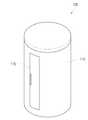
Translated fromKorean도 1a 및 도1b은 본 발명에 따른 화상형성장치의 외관 구성을 도시한 사시도,1A and 1B are perspective views showing an external configuration of an image forming apparatus according to the present invention,
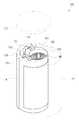
도 2a 및 도2b는 본 발명에 따른 화상형성장치의 케이싱 구성을 도시한 사시도,FIGS. 2A and 2B are perspective views illustrating a casing structure of an image forming apparatus according to the present invention;
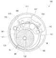
도 3은 본 발명의 바람직한 실시예에 따른 화상형성장치의 단면구성을 도시한 단면도,3 is a cross-sectional view illustrating a cross-sectional configuration of an image forming apparatus according to a preferred embodiment of the present invention,
도 4는 본 발명의 바람직한 실시예에 따른 인쇄매체의 단면구성을 도시한 단면도,4 is a cross-sectional view illustrating a cross-sectional configuration of a print medium according to a preferred embodiment of the present invention,
도 5a 내지 도5e는 본 발명의 바람직한 실시예에 따른 화상형성장치의 동작과정을 도시한 예시도,5A to 5E are diagrams illustrating an operation process of an image forming apparatus according to a preferred embodiment of the present invention,
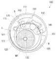
도 6은 본 발명의 제2실시예에 따른 화상형성장치의 구성을 도시한 단면도,6 is a sectional view showing a configuration of an image forming apparatus according to a second embodiment of the present invention,
도 7은 본 발명의 또 다른 실시예에 따른 화상형성장치의 구성을 도시한 단면도이다.7 is a cross-sectional view showing the configuration of an image forming apparatus according to another embodiment of the present invention.
* 도면의 주요 부분에 대한 부호의 설명DESCRIPTION OF THE REFERENCE NUMERALS
100 : 화상형성장치 110 : 케이싱100: image forming apparatus 110: casing
111 : 본체케이싱 113 : 커버111: main body casing 113: cover
120 : 지지프레임 121 : 안내면120: support frame 121: guide surface
123 : 인쇄매체수용부 130 : 인쇄매체공급코더123: print medium accommodating portion 130: print medium supply coder
140 : 인쇄매체이송수단 150 : 화상형성부140: print medium feeding means 150:
160 : 인쇄매체지지프레임 161 : 인쇄매체지지리브160: print medium support frame 161: print medium support rib
170 : 절단기170: Cutter
본 발명은 화상형성장치에 관한 것으로서, 보다 상세하게는 휴대가 간편한 화상형성장치에 관한 것이다.The present invention relates to an image forming apparatus, and more particularly, to an image forming apparatus that is easy to carry.
화상형성장치는 화상데이타가 저장된 호스트에 연결되어 호스트의 출력신호에 따라 인쇄매체에 화상데이타를 가시화하는 장치이다. 이런 화상형성장치는 화상을 형성하는 방법과 기능에 따라 잉크젯방식, 전자사진방식, 염료승화방식 등으로 분류할 수 있다.The image forming apparatus is connected to a host where image data is stored, and visualizes the image data on a print medium in accordance with an output signal of the host. Such an image forming apparatus can be classified into an inkjet method, an electrophotographic method, and a dye sublimation method depending on the method and function of forming an image.
최근 기술이 발전함에 따라 화상형성장치는 휴대가 간편한 호스트장치와 결합되어 직접 화상데이타를 송수신하는 것이 가능해졌다. 특히, 휴대가 간편한 디지털카메라와 휴대폰의 포토 화상데이타 촬영기술이 발전하고 그 사용이 급증함에 따라 사용자가 촬영한 포토 화상데이타를 사용자가 직접 화상형성장치를 통하여 출력하는 경우가 빈번해졌다.As the latest technology develops, the image forming apparatus can be coupled with a host device that is easy to carry and can transmit and receive image data directly. Particularly, as the photo image data capturing technology of a portable digital camera and a cellular phone has been developed and its usage has been rapidly increasing, there have been frequent cases where a user directly outputs photo image data through an image forming apparatus.
이에 따라 포토 화상데이타를 출력하기 위한 포토 화상데이타 전용 화상형성 장치의 개발이 가속화되고 있으며, 이 중 염료승화방식(Dye Sublimation Type)은 습기 및 물성에 따른 화상 변질이 적고 장기간 보존이 가능하며 높은 해상도를 가지고 있어 포토 화상데이타 전용 화상형성장치에 널리 사용되고 있다.Accordingly, development of an image forming apparatus dedicated to photo image data for outputting photo image data has been accelerated. Among them, the dye sublimation type has a low image deterioration due to moisture and physical properties, can be stored for a long time, And is widely used for a photo image data dedicated image forming apparatus.
그러나, 종래 포토 화상데이타 전용 화상형성장치는 전체 크기가 휴대하기에는 커서 사용자가 이동시 휴대하면서 즉시 화상데이타를 출력하는데는 무리가 있었다.However, the conventional photo image data-dedicated image forming apparatus is so large that the entire size of the image forming apparatus is portable, and it is difficult for the user to immediately output image data while carrying it while moving.
또한, 종래 포토 화상데이타 전용 화상형성장치는 본체 내부에 인쇄매체를 적재하는 인쇄매체적재부가 없어 사용자가 수동으로 인쇄매체를 급지해야 하는 번거로움이 있었으며, 이에 따라 다수의 화상데이타를 동시에 출력하고자 할 경우 연속출력이 되지 않는 불편함이 있었다.In addition, the conventional photo image data-dedicated image forming apparatus has a problem that it is troublesome for the user to manually feed the print medium because there is no print medium loading unit for loading the print medium inside the main body. Accordingly, There is inconvenience that continuous output can not be performed.
그리고, 종래 화상형성장치는 사용자가 이동해야 하는 경우 화상이 형성된 인쇄매체가 화상형성장치 외부로 노출되므로 사용자가 직접 휴대해야 하는 번거로움이 있었다. 또한, 휴대하는 과정에서 인쇄매체 표면이 오염되는 문제도 있었다.In the conventional image forming apparatus, when the user has to move, the print medium on which the image is formed is exposed to the outside of the image forming apparatus, so that the user has to carry it directly. In addition, there has been a problem that the surface of the print medium is contaminated during carrying.
따라서, 본 발명의 목적은 휴대가 간편하며 화상형성이 완료된 인쇄매체가 케이싱 내에 수용될 수 있는 화상형성장치를 제공하는 것이다.SUMMARY OF THE INVENTION Accordingly, it is an object of the present invention to provide an image forming apparatus in which a print medium which is easy to carry and has been subjected to image formation can be received in a casing.
상기 목적은, 본 발명에 따라 모바일 화상형성장치에 있어서, 케이싱과; 상기 케이싱 내에 인쇄매체가 감겨있는 인쇄매체롤을 감싸도록 마련되어 상기 인쇄매체를 이송안내하는 지지프레임과; 상기 지지프레임을 따라 이송안내된 상기 인쇄매 체에 화상을 형성하는 화상형성부와; 상기 케이싱과 상기 지지프레임 사이에 마련되어 상기 화상형성부에서 화상이 형성된 인쇄매체가 수용되는 인쇄매체수용부를 포함하는 것을 특징으로 하는 모바일 화상형성장치에 의해 달성될 수 있다.The above object is achieved by a mobile image forming apparatus according to the present invention, comprising: a casing; A support frame provided to enclose the print medium roll in which the print medium is wound, and to guide the print medium; An image forming unit that forms an image on the printing medium conveyed and guided along the support frame; And a print medium accommodating portion which is provided between the casing and the support frame and accommodates a print medium on which an image is formed in the image forming portion.
여기서, 상기 지지프레임 내에 마련되어 상기 인쇄매체롤을 회전가능하게 수용하고 상기 인쇄매체를 상기 화상형성부로 공급하는 인쇄매체공급코어를 더 포함할 수 있다.Here, the printing medium supply core may further include a print medium supply core provided in the support frame for rotatably receiving the print medium roll and supplying the print medium to the image forming portion.
그리고, 상기 인쇄매체공급코어는 상기 케이싱의 단면형상의 중심영역에 마련될 수 있다.The print medium supply core may be provided in a central region of the cross-sectional shape of the casing.
또한, 상기 인쇄매체공급코어와 상기 화상형성부 사이에 마련되어 상기 인쇄매체공급코어에서 공급되는 인쇄매체를 소정 길이로 절단하는 절단기를 더 포함할 수 있다.The apparatus may further include a cutter provided between the print medium supply core and the image forming unit to cut the print medium supplied from the print medium supply core to a predetermined length.
한편, 상기 케이싱에는 상기 인쇄매체수용부의 적어도 일영역을 외부로 노출하는 개구가 형성되는 것이 바람직하다.Preferably, the casing is provided with an opening exposing at least one region of the print medium receiving portion to the outside.
또한, 상기 케이싱에 회동가능하게 결합하여 상기 개구를 개폐하는 도어를 더 포함할 수 있다.The apparatus may further include a door rotatably coupled to the casing to open and close the opening.
여기서, 상기 케이싱은 원통형으로 마련될 수 있다.Here, the casing may be provided in a cylindrical shape.
또한, 상기 케이싱은 단면형상이 다각형으로 마련될 수 있다.In addition, the casing may have a polygonal cross-sectional shape.
그리고, 상기 케이싱은 상기 화상형성부와 상기 지지프레임을 수용하는 케이싱본체와, 상기 케이싱본체에 착탈가능하게 결합하여 상기 인쇄매체롤을 교체가능하게 하는 케이싱커버를 포함하는 것이 바람직하다.Preferably, the casing includes a casing main body for accommodating the image forming portion and the support frame, and a casing cover detachably coupled to the casing main body to allow the print medium roll to be replaced.
한편, 상기 인쇄매체수용부는 상기 케이싱의 내벽면으로부터 돌출 형성되어 상기 화상형성이 완료된 인쇄매체의 후단을 지지하는 인쇄매체지지리브를 포함하는 것이 바람직하다.Preferably, the print medium receiving portion includes a print medium supporting rib formed to protrude from the inner wall surface of the casing and to support a rear end of the print medium on which the image is formed.
여기서, 상기 인쇄매체수용부는 복수의 인쇄매체를 수용할 수 있게 마련될 수 있다.Here, the print medium receiving portion may be provided to accommodate a plurality of print media.
한편, 상기 화상형성부는, 상기 인쇄매체에 열을 가하는 감열프린트헤드와, 상기 감열프린트헤드에 대해 인쇄매체를 지지하는 플래튼을 포함할 수 있다.On the other hand, the image forming section may include a thermosensitive print head for applying heat to the print medium, and a platen for supporting the print medium with respect to the thermal print head.
또한, 상기 화상형성부는, 상기 감열프린트헤드의 일측에 마련되어 잉크리본을 공급하는 잉크리본공급코어와, 상기 잉크리본을 환수하는 잉크리본환수코어를 더 포함할 수 있다.The image forming unit may further include an ink ribbon supply core provided on one side of the thermal print head to supply an ink ribbon, and an ink ribbon receiving core for returning the ink ribbon.
한편, 상기 인쇄매체공급롤의 인쇄매체를 상기 화상형성부로 이송하는 이송롤러와; 상기 화상형성부에서 화상형성이 완료된 인쇄매체를 상기 인쇄매체수용부로 이송하는 배출롤러를 더 포함할 수 있다.A conveying roller for conveying the print medium of the print medium supply roll to the image forming unit; And a discharge roller for transferring the print medium having undergone image formation in the image forming portion to the print medium containing portion.
그리고, 상기 이송롤러와 상기 배출롤러는 정역회전이 가능하게 마련될 수 있다.The feed roller and the discharge roller may be rotated in the forward and reverse directions.
한편, 상기 이송롤러와, 상기 배출롤러 및 상기 화상형성부는 상기 인쇄매체코어를 중심으로 원호상으로 배치되는 것이 바람직하다.It is preferable that the conveying roller, the discharge roller, and the image forming unit are disposed in an arc-shape with the print medium core as a center.
한편, 상기 지지프레임은 상기 이송롤러와 상기 배출롤러가 역회전시 역이송된 인쇄매체를 수용하는 인쇄매체역이송로가 형성되는 것이 바람직하다.Preferably, the supporting frame is formed with a printing medium reverse conveying path for receiving the printing medium conveyed in the reverse direction when the conveying roller and the discharging roller are reversely rotated.
여기서, 상기 인쇄매체역이송로는 상기 인쇄매체수용부와 연결되도록 형성되 는 것이 바람직하다.Here, the printing medium reverse feed path may be connected to the print medium receiving portion.
한편, 상기 이송롤러의 일측에 마련되어 상기 인쇄매체가 역이송시 상기 인쇄매체를 상기 인쇄매체역이송로로 안내하는 방향절환레버를 더 포함하는 것이 바람직하다.The apparatus may further include a direction switching lever which is provided at one side of the conveying roller and guides the print medium to the printing medium reverse conveying path when the printing medium is conveyed in the reverse direction.
이하에서는 첨부도면을 참조하여 본 발명에 대해 상세히 설명한다.Hereinafter, the present invention will be described in detail with reference to the accompanying drawings.
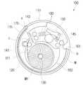
도 1a 및 도1b는 본 발명의 바람직한 실시예에 따른 화상형성장치(100)의 외관을 도시한 사시도이고, 도2는 본 발명의 바람직한 실시예에 따른 화상형성장치(100)의 내구구성을 도시한 사시도이다. 도시된 바와 같이 본 발명에 따른 화상형성장치(100)는 케이싱(110)과, 케이싱(110) 내에 마련되어 인쇄매체롤(MR)에 감긴 인쇄매체를 화상형성부(150) 측으로 안내하는 지지프레임(120)과, 인쇄매체(M)에 화상을 형성하는 화상형성부(150)와, 화상형성이 완료된 인쇄매체가 수용되는 인쇄매체수용부(160)를 포함한다.FIG. 1 is a perspective view showing the appearance of an
또한, 화상형성장치(100)는 지지프레임(120) 내에 마련되어 인쇄매체를 공급하는 인쇄매체공급코어(130)와, 화상형성부(150)와 인쇄매체수용부(160)로 인쇄매체를 이송하는 인쇄매체이송수단(140)과, 인쇄매체를 소정 길이로 절단하는 절단기(170)를 포함한다.The
케이싱(110)은 도시된 바와 같이 인쇄매체(M)가 외부로 드러나지 않도록 밀폐된 공간을 형성한다. 본 발명의 바람직한 실시예에 따른 케이싱(110)은 원통형으로 마련된다. 케이싱(110)의 높이는 인쇄매체(M)의 폭과 구동부(미도시)의 부피를 고려하여 결정될 수 있다. 케이싱(110)은 지지프레임(120)과 화상형성부(150)를 수 용하는 본체케이싱(111)과, 본체케이싱(111)의 상측에 마련되어 본체케이싱(111)을 커버하는 커버(117)를 포함한다. The
본체케이싱(111)은 화상이 형성된 인쇄매체를 배출할 수 있는 개구(113)와, 개구(113)를 커버하는 도어(115)를 포함한다. 개구(113)는 화상이 형성된 인쇄매체가 수용된 인쇄매체수용부(160)의 적어도 일영역이 외부로 드러날 수 있는 크기로 마련된다. 본 발명의 바람직한 실시예에 따른 개구(113) 및 도어(115)는 도1a 및 도1b 에 도시된 바와 같이 본체케이싱(111)의 일영역에 인쇄매체(M)의 선단(a)만 드러나도록 형성된다. 이에 따라 사용자는 화상형성이 완료되면 도어(115)를 개방하여 인쇄매체의 선단(a)을 외부로 이탈시켜 인쇄매체를 배출할 수 있다. 이 때, 도어(115)의 높이(h)는 인쇄매체(M)의 폭 보다 크게 형성되는 것이 사용자가 용이하게 인쇄매체를 배출할 수 있어 바람직하다.The
한편, 본 발명의 또 다른 실시예에 따른 개구(113) 및 도어(115)는 도2b에 도시된 바와 같이 케이싱(110)의 일영역(114)이 다른 영역(112)에 대해 회동가능하게 마련된다. 즉, 개구(113)가 인쇄매체수용부 전체를 외부로 노출하도록 개방된다. 이 때, 도어는 케이싱(110)에 별도로 형성되지 않고 케이싱(110)의 일영역(114)이 도어가 된다. 이 경우 도2a에 도시된 케이싱(110)과 비교하였을 때 인쇄매체수용부(160)에 복수의 인쇄매체(M)가 수용되어 있는 경우 사용자가 한꺼번에 인쇄매체(M)를 배출하기 용이한 장점이 있다.The opening 113 and the
이 외에도 개구(113) 및 도어(115)는 케이싱(110)의 크기와 인쇄매체(M)의 크기, 인쇄매체(M)의 인쇄용량 등을 고려하여 다양한 크기로 마련될 수 있다.The
커버(117)는 도2a에 도시한 바와 같이 본체케이싱(111)의 상면에 착탈가능하게 결합한다. 커버(117)는 인쇄매체롤(MR)에 감겨있는 인쇄매체(M)가 소진된 경우 인쇄매체롤(MR)을 교환하기 위해 착탈될 수 있다. 또한, 인쇄경로상에 인쇄매체(M)의 걸림이 발생한 경우 이를 해결하기 위해 사용될 수 있다. 그리고, 경우에 따라 본체케이싱(111)에 개구(113)가 없는 경우 화상형성이 완료된 인쇄매체(M)를 배출하기 위해 사용될 수 있다. 커버(117)와 본체케이싱(111)의 착탈구조는 공지된 결합구조가 사용될 수 있으므로 자세한 설명은 생략한다.The
지지프레임(120)은 도2와 도3에 도시된 바와 같이 케이싱(110) 내에서 인쇄매체롤(MR)을 지지하고 인쇄매체롤(MR)로부터 공급된 인쇄매체(M)를 화상형성부(150) 측으로 안내한다. 지지프레임(120)은 인쇄매체롤(MR)을 감싸도록 나선형의 형상으로 마련된다. 지지프레임(120)은 인쇄매체롤(MR)을 지지하는 인쇄매체수용부(160)와, 인쇄매체(M)를 안내하는 안내면(121)을 포함한다. The
인쇄매체수용부(160)는 케이싱(110)의 내벽면을 따라 소정 공간을 두고 인쇄매체롤(MR)을 감싸는 형태로 마련된다. 인쇄매체수용부(160)는 인쇄매체롤(MR)의 최대 두께를 고려하여 마련될 수 있다.The print
안내면(121)은 인쇄매체수용부(160)로부터 연장형성되며 소정의 곡면을 형성한다. 안내면(121)은 인쇄매체(M)가 인쇄매체롤(MR)로부터 나선형의 이송경로를 따라 이송되도록 형성된 곡면을 갖는다. 일반적으로 인쇄매체(M)는 직선으로 나아가려 하는 성질을 갖는다. 따라서, 안내면(121)은 인쇄매체(M)의 선단(a)이 픽업롤러(141)에 진입할 때까지 인쇄매체(M)와 접촉하면서 인쇄매체(M)를 안내한다.The
한편 지지프레임(120)은 케이싱(110)과 소정 간격(d) 이격 형성된다. 여기서, 지지프레임(120)과 케이싱(110) 사이의 이격간격(d)은 화상이 형성된 인쇄매체(M)가 수용되는 인쇄매체수용부(160)를 형성한다. 인쇄매체수용부(160)에 대해서는 해당 부분에서 자세히 설명하도록 한다.On the other hand, the
인쇄매체공급코어(130)는 인쇄매체(M)가 감겨있는 인쇄매체롤(MR)을 회전가능하게 지지하여 인쇄매체(M)를 화상형성부(150)로 공급하도록 한다. 인쇄매체공급코어(130)는 인쇄매체롤(MR)의 중심영역을 지지하여 구동부(미도시)의 구동에 따라 회동한다.The print
화상형성부(150)는 인쇄매체공급코어(130)로부터 공급된 인쇄매체(M)에 화상을 형성한다. 본 발명의 바람직한 실시예에 따른 화상형성부(150)는 감열방식에 의해 인쇄매체(M)에 화상을 형성한다. 일반적으로 감열방식 화상형성부(150)는 인쇄매체에 열을 가하는 감열프린트헤드(151)와, 감열프린트헤드(151)에 대해 인쇄매체(M)를 지지하는 플래튼(153)을 포함한다.The
이 때, 인쇄매체(M)는 감열프린트헤드(151)의 가열 온도 및 시간에 따라 색상이 선택되어 칼라 화상을 제공하는 매체로서, 통상적인 인쇄매체로 이용되는 종이와는 다르다. 즉, 인쇄매체(M)는 도4에 도시된 바와 같이 투명한 기판(1)을 구비하고, 이 기판(1) 상부에 제1화상형성층(2), 스페이서(3), 제2화상형성층(4) 및 상부 보호층(5)이 순차로 형성되어 있다. 그리고, 상기 기판(1) 하부에는 제3화상형성층(6), 반사층(7) 및 하부보호층(8)이 순차로 형성되어 있다.At this time, the print medium M is a medium for selecting a color according to the heating temperature and time of the
제1 내지 제3화상형성층(2)(4)(6)은 서로 다른 칼라를 구현하는 층으로, 그 각각은 옐로우(Y), 마젠타(M), 시안(C) 색상의 류코 염료(leuco dye)와 현상재로 이루어진다. 스페이서(3)는 상기 제1화상형성층(2)과 제2화상형성층(4)을 구분하기 위한 층으로, 상부 보호층(5) 상에서, 제1 및 제3화상형성층(2)(6)에 형성된 칼라를 볼 수 있도록 투명한 소재로 되어 있다. 여기서, 제1 내지 제3화상형성층(2)(4)(6)은 서로 다른 가열온도 및 가열시간에 의해 감응하여 칼라를 표현한다.Each of the first to third
본 발명의 바람직한 실시예에 따른 인쇄매체(M)는 상술한 잉크층을 갖는 구조로 인쇄매체롤(MR)에 감겨 있는 상태로 인쇄매체공급코어(130)에 결합한다.The print medium M according to the preferred embodiment of the present invention is coupled to the print
감열프린트헤드(151)는 미세한 크기의 다수의 발열소자가 인쇄매체(M)의 폭에 대응하도록 소정간격으로 배열되어 있다. 여기서, 발열소자의 개수는 화상형성장치(1)의 해상도를 좌후하게 되므로 적절한 개수로 설계할 수 있다. 각 발열소자는 화상형성을 위해 개별적으로 열을 발생하도록 제어된다. 또한, 각 발열소자는 인쇄매체의 각 색상의 잉크층(2,4,6)이 감열하여 화상을 나타내는 온도가 서로 다르므로 서로 다른 온도를 낼 수 있도록 제어된다.The
감열프린트헤드(151)는 인쇄매체(M)가 공급되기 전에는 플래튼(153)으로부터 이격되어 대기하고, 인쇄매체(M)가 공급하면 플래튼(153)으로 접근하여 인쇄매체(M)에 열과 압력을 가하게 된다. 여기서, 감열프린트헤드(151)는 복수개로 마련될 수 있다. 감열프린트헤드(151)의 구성은 공지된 구성과 동일하므로 자세한 설명은 생략한다.The
인쇄매체이송수단(140)은 안내면(121)에 의해 이송안내된 인쇄매체(M)를 화상형성부(150)로 이송하고, 화상형성부(150)에서 화상이 형성된 인쇄매체(M)를 인 쇄매체수용부(160)로 이송한다. 인쇄매체이송수단(140)은 인쇄매체공급코어(130) 측에 마련되어 인쇄매체(M)의 안내면(121)에 의해 이송된 인쇄매체(M)의 선단을 픽업하는 픽업롤러(141)와, 픽업롤러(141)로부터 이송된 인쇄매체(M)를 화상형성부(150)로 이송하는 이송롤러(143)와, 화상형성부(150)에서 화상형성이 완료된 인쇄매체(M)를 인쇄매체수용부(160)로 이송하는 배출롤러(145)를 포함한다. 그리고, 인쇄매체이송수단(140)은 이송롤러(143)와 화상형성부(150) 사이, 화상형성부(150)와 인쇄매체수용부(160) 사이에 각각 마련되어 인쇄매체(M)의 이송을 안내하는 가이드부재(147)를 더 포함한다.The print medium feeding means 140 feeds the print medium M conveyed and guided by the
여기서, 픽업롤러(141), 이송롤러(143), 배출롤러(145) 및 가이드부재(147)는 화상형성부(150)를 포함하여 인쇄매체롤(MR)을 중심으로 원호상에 배치된다. 따라서, 인쇄매체(M)의 화상형성경로도 인쇄매체롤(MR)을 중심으로 원호를 그리며 전체적으로 나선형상으로 진행된다.The
가이드부재(147)는 인쇄매체(M)가 나선형의 화상형성경로를 유지하며 진행할 수 있도록 인쇄매체(M)를 안내한다.The
인쇄매체수용부(160)는 화상형성부(150)에서 화상형성이 완료된 인쇄매체(M)가 수용된다. 인쇄매체수용부(160)는 케이싱(110)과 지지프레임(120) 사이의 이격공간에 마련된다. 인쇄매체수용부(160)의 인쇄매체 수용량은 케이싱(110)의 내벽면과 지지프레임(120) 사이의 이격간격(d)에 따라 결정될 수 있다. 그러나, 이격간격(d)을 크게 할 경우 케이싱(110)의 전체 체적과 크기가 증가하게 되므로 사용자가 휴대하기 불편할 수 있다. 따라서, 이격간격(d)은 휴대가능성을 고려하여 적절 하게 설계하는 것이 바람직하다.The print
인쇄매체수용부(160)의 길이는 인쇄매체(M)의 길이에 대응되게 마련되는 것이 바람직하다. 인쇄매체수용부(160)의 길이가 인쇄매체(M)의 길이보다 길 경우 인쇄매체(M)가 인쇄매체수용부(160) 내에서 유동할 수 있으므로 인쇄매체(M) 표면의 화상이 내벽면에 접촉되며 오염될 수 있다. 따라서, 바람직하게는 인쇄매체수용부(160)의 길이는 인쇄매체(M)가 유동되지 않고 수용될 수 있는 길이로 마련되는 것이 바람직하다.It is preferable that the length of the print
여기서, 인쇄매체수용부(160)는 케이싱(110)의 내벽면으로부터 돌출 형성되어 인쇄매체수용부(160)에 수용된 인쇄매체(M)의 유동을 저지하도록 인쇄매체(M)의 후단(b)을 지지하는 인쇄매체지지리브(161)를 포함할 수 있다. 인쇄매체지지리브(161)는 배출롤러(145)의 일측에 케이싱(110)의 내벽면으로 돌출형성되어 배출롤러(145)를 경유하여 인쇄매체수용부(160)로 진입한 인쇄매체(M)의 후단(b)을 지지한다. 인쇄매체지지리브(161)의 일면은 인쇄매체(M)가 배출롤러(145) 측으로 이동하는 것을 방지하기 위해 곡면형상으로 마련되는 것이 바람직하다.The print
한편, 인쇄매체롤(MR)이 말려있는 롤 형태인 경우 픽업롤러(141)와 이송롤러(143) 사이에는 인쇄매체(M)를 소정길이로 절단하는 절단기(170)가 마련될 수 있다. 절단기(170)는 인쇄매체롤(MR)을 정해진 기준길이로 절단하거나, 화상데이타의 크기에 따라 제어부(미도시)의 제어신호에 대응하여 가변길이로 절단할 수 있다. 절단기(170)는 상하로 승강가능하게 마련되어 인쇄매체(M)를 절단한다.A
인쇄매체롤(MR)이 말려있는 롤 형태가 아니거나, 인장력이 가해질 경우 절단 가능하도록 절단선이 형성되어 있는 경우 절단기(170)가 없을 수 있다.The
한편, 도면에 도시되지 않았으나 케이싱(110)의 바닥면에는 인쇄매체이송수단(140)과 화상형성부(150)를 구동하는 구동부(미도시)와, 이들을 제어하는 제어부(미도시)가 마련된다. 또한, 바닥면에는 화상데이타가 저장된 메모리가 장착되는 메모리장착부(미도시)가 마련될 수 있다.Although not shown in the drawing, a driving unit (not shown) for driving the printing medium transferring unit 140 and the
이러한 구성을 갖는 본 발명의 바람직한 실시예에 따른 화상형성장치(100)의 화상형성과정을 도1a 내지 도5e를 참조로 설명한다. 먼저, 사용자는 도2a에 도시된 바와 같이 커버(117)를 개방하고 인쇄매체공급코어(130)에 인쇄매체롤(MR)을 결합시킨다. 그리고, 커버(117)를 본체케이싱(111)에 결합시킨다. 인쇄신호가 인가되면 인쇄매체공급코어(130)는 회전하고 인쇄매체(M)는 픽업롤러(141) 측으로 이동한다. 도5a에 도시된 바와 같이 이동하는 인쇄매체(M)의 선단(a)은 안내면(121)을 따라 이동하여 픽업롤러(141)에 맞물린다. 픽업롤러(141)에 맞물린 인쇄매체(M)의 선단(a)은 이송롤러(143)를 경유하여 화상형성부(150)로 안내된다.The image forming process of the
화상형성부(150)의 감열프린트헤드(151)는 인쇄매체(M)에 열을 가하고 각 색상의 잉크층이 감열하여 컬러화상을 형성하게 된다. 화상형성이 완료된 인쇄매체(M)의 선단(a)은 도5b에 도시된 바와 같이 배출롤러(145)를 경유하여 인쇄매체수용부(160)로 진입한다. 이 때, 인쇄매체롤(MR)에서는 인쇄매체(M)를 계속공급하고, 인쇄매체(M)의 길이가 기준길이로 감지되었을 때 도5c에 도시된 바와 같이 절단기(170)가 인쇄매체(M)를 절단한다.The
절단된 인쇄매체(M)의 후단(b)은 화상형성부(150)를 경유하여 인쇄매체수용 부(160)로 진입하고, 인쇄매체지지리브(161)에 의해 지지된다. 즉, 화상형성이 완료된 인쇄매체(M)는 도5d에 도시된 바와 같이 인쇄매체수용부(160)에 수용된 상태로 유지된다. 인쇄매체(M)의 선단(a)은 도어(115)에 대응하는 측에 위치하고 인쇄매체(M)의 후단(b)은 인쇄매체지지리브(161)에 의해 지지된 상태로 유지된다.The rear end b of the cut print medium M enters the print
연속하여 인쇄신호가 인가되면 인쇄매체롤(MR)에 감겨 있는 인쇄매체(M)가 다시 화상형성부(150)로 공급되고, 화상이 형성된 인쇄매체(M)는 인쇄매체수용부(160)에 먼저 수용된 인쇄매체와 함께 수용된다.The printing medium M wrapped around the printing medium roll MR is supplied to the
사용자는 화상이 형성된 인쇄매체(M)를 인쇄매체수용부(160)에 수용한 채 화상형성장치(100)를 휴대하거나 도5e에 도시된 바와 같이 도어(115)를 개방하여 인쇄매체(M)를 외부로 배출할 수 있다.The user carries the
한편, 도6은 본 발명의 제2실시예에 따른 화상형성장치(100′)의 구성을 개략적으로 도시한 단면도이다. 설명에 앞서 상술한 바람직한 실시예에 따른 화상형성장치(100)와 동일한 부분에 대해서는 설명을 생략함을 밝힌다.6 is a cross-sectional view schematically showing a configuration of an image forming apparatus 100 'according to a second embodiment of the present invention. Prior to the description, the same parts as those of the
본 발명의 제2실시예에 따른 화상형성장치(100′)는 화상형성부(150′)가 열전사방식을 사용한다. 화상형성부(150′)는 잉크리본(R)를 인쇄매체(M)에 가열가압하여 잉크리본(R)에 코팅된 잉크를 인쇄매체(M)로 전사하여 화상을 형성한다. 이 때, 잉크리본(R)은 옐로우, 마젠타, 시안의 세 가지 색상별로 분리되어 화상이 형성되므로 인쇄매체(M)는 화상형성부(150′)를 적어도 세 번 왕복이송된다.In the image forming apparatus 100 'according to the second embodiment of the present invention, the image forming unit 150' uses a thermal transfer method. The image forming unit 150 'forms an image by transferring the ink coated on the ink ribbon R onto the print medium M by heating and pressing the ink ribbon R onto the print medium M. At this time, since the ink ribbon R is divided into three colors of yellow, magenta, and cyan to form an image, the print medium M is conveyed at least three times by the image forming unit 150 '.
이를 위해 화상형성부(150′)는 잉크리본(R)을 화상형성부(150′)로 공급하는 잉크리본공급코어(155)와, 사용된 잉크리본(R)을 회수하는 잉크리본환수코 어(157)를 포함한다.To this end, the image forming unit 150 'includes an ink
한편, 인쇄매체(M)의 왕복이송을 위해 이송롤러(143) 및 배출롤러(145)는 정역회전 가능하게 마련된다. 그리고, 지지프레임(120)에는 역이송된 인쇄매체(M)가 수용되는 인쇄매체역이송로(125)가 형성된다. 인쇄매체역이송로(125)는 도시된 바와 같이 인쇄매체수용부(160)와 연결되게 마련될 경우 공간을 절약할 수 있어 바람직하다.On the other hand, the
픽업롤러(141)와 이송롤러(143) 사이에는 인쇄매체(M)의 이송경로를 변경하는 방향전환레버(149)가 마련된다. 방향전환레버(149)는 회전가능하게 마련되어 인쇄매체롤(MR)로부터 인쇄매체(M)가 공급될 경우 점선으로 표시된 바와 같이 위로 회전하여 인쇄매체(M)가 이송롤러(143)로 공급되도록 한다. 또한, 방향전환레버(149)는 절단기(170)에 의해 인쇄매체(M)가 절단되고 나면 실선으로 표시된 바와 같이 아래로 회전하여 인쇄매체(M)의 후단을 인쇄매체역이송로(125)로 안내한다.Between the pick-up
이러한 구성을 갖는 본 발명의 제2실시예에 따른 화상형성장치(100′)의 화상형성방법을 설명하면 인쇄매체(M)가 화상형성부(150)로 공급되면 감열프린트헤드(151)는 잉크리본(R)을 인쇄매체(M)에 가열가압하여 옐로우 색상의 화상을 형성한다. 그리고 이송롤러(143)와 배출롤러(145)는 역회전하여 인쇄매체(M)를 역이송한다. 이 때, 방향전환레버(149)는 아래로 회전하고 옐로우의 화상이 형성된 인쇄매체는 인쇄매체역이송로(125)로 이송된다. 그리고, 이송롤러(143)는 다시 인쇄매체(M)의 선단을 화상형성부(150)로 공급하여 마젠타 색상의 화상을 형성한다.When the print medium M is supplied to the
이러한 인쇄매체의 이송과 역이송을 반복하여 인쇄매체에 화상형성이 완료되 면 인쇄매체(M)는 인쇄매체수용부(160)에 수용된다.When the image formation on the print medium is completed by repeating the conveyance and the reverse conveyance of the print medium, the print medium M is received in the print
한편, 상술한 본 발명의 바람직한 실시예와 제2실시예에 따른 화상형성장치(100, 100′)는 케이싱(110)의 원통형으로 이루어진 것으로 설명하였으나 도7에 도시된 바와 같이 본 발명의 또 다른 실시예에 따른 화상형성장치(100″)는 케이싱(110)이 사각형으로 마련된다. 이 외에도 케이싱(110)은 여타 다각형 형상으로 마련될 수도 있다.Meanwhile, although the
이상 설명한 바와 같이, 본 발명에 따르면 인쇄매체가 케이싱 내에 수용되고 화상이 형성된 인쇄매체도 케이싱 내에 수용되어 사용자가 간편하게 휴대할 수 있는 화상형성장치가 제공된다.As described above, according to the present invention, there is provided an image forming apparatus in which a print medium is housed in a casing and a print medium on which an image is formed is also housed in the casing, so that the user can easily carry the print medium.
또한, 인쇄매체가 케이싱 내에 적재되어 있으므로 사용자가 수동으로 공급할 필요가 없으며, 복수의 인쇄매체에 연속출력이 가능하다.Further, since the printing medium is loaded in the casing, it is not necessary for the user to manually supply the printing medium, and continuous printing is possible on a plurality of printing mediums.
Claims (19)
Translated fromKoreanPriority Applications (2)
| Application Number | Priority Date | Filing Date | Title |
|---|---|---|---|
| KR1020070061533AKR101391749B1 (en) | 2007-06-22 | 2007-06-22 | Mobile image forming apparatus |
| US11/945,487US8371763B2 (en) | 2007-06-22 | 2007-11-27 | Mobile image forming apparatus |
Applications Claiming Priority (1)
| Application Number | Priority Date | Filing Date | Title |
|---|---|---|---|
| KR1020070061533AKR101391749B1 (en) | 2007-06-22 | 2007-06-22 | Mobile image forming apparatus |
Publications (2)
| Publication Number | Publication Date |
|---|---|
| KR20080112745A KR20080112745A (en) | 2008-12-26 |
| KR101391749B1true KR101391749B1 (en) | 2014-05-07 |
Family
ID=40136630
Family Applications (1)
| Application Number | Title | Priority Date | Filing Date |
|---|---|---|---|
| KR1020070061533AExpired - Fee RelatedKR101391749B1 (en) | 2007-06-22 | 2007-06-22 | Mobile image forming apparatus |
Country Status (2)
| Country | Link |
|---|---|
| US (1) | US8371763B2 (en) |
| KR (1) | KR101391749B1 (en) |
Families Citing this family (3)
| Publication number | Priority date | Publication date | Assignee | Title |
|---|---|---|---|---|
| US8029202B2 (en)* | 2008-03-14 | 2011-10-04 | Citizen Holdings Co., Ltd. | Printer with recording paper leading edge storage unit |
| JP5937934B2 (en)* | 2012-09-20 | 2016-06-22 | シチズンホールディングス株式会社 | Paper discharge device and printer |
| USD714863S1 (en)* | 2013-12-10 | 2014-10-07 | Gfi Innovations, Inc. | Cartridge for ink |
Citations (3)
| Publication number | Priority date | Publication date | Assignee | Title |
|---|---|---|---|---|
| JP2004216732A (en)* | 2003-01-15 | 2004-08-05 | Fuji Photo Film Co Ltd | Color thermal printer |
| US20050162497A1 (en)* | 2004-01-22 | 2005-07-28 | Casio Computer Co., Ltd. | Portable electronic apparatus |
| WO2006123865A1 (en)* | 2005-05-20 | 2006-11-23 | Prinics Co., Ltd. | Printer cartridge unifying thermal ribbon and transfer medium and thermal transfer printer employing the same |
Family Cites Families (15)
| Publication number | Priority date | Publication date | Assignee | Title |
|---|---|---|---|---|
| JPH06312557A (en)* | 1993-04-28 | 1994-11-08 | Nec Home Electron Ltd | Printer |
| JPH08300758A (en)* | 1995-04-28 | 1996-11-19 | Ricoh Co Ltd | Recording apparatus |
| JP3494783B2 (en)* | 1995-12-07 | 2004-02-09 | 富士写真フイルム株式会社 | Thermal printing method and apparatus |
| AUPP702798A0 (en)* | 1998-11-09 | 1998-12-03 | Silverbrook Research Pty Ltd | Image creation method and apparatus (ART70) |
| JP2000168194A (en)* | 1998-12-08 | 2000-06-20 | Seiko Epson Corp | Electronic devices and printers |
| JP2001080130A (en)* | 1999-09-17 | 2001-03-27 | Osaka Gas Co Ltd | Portable printing apparatus |
| JP2001130057A (en)* | 1999-11-02 | 2001-05-15 | Canon Inc | Portable electronic devices |
| JP3541156B2 (en)* | 2000-02-23 | 2004-07-07 | シャープ株式会社 | Printer for packaging |
| JP2002011908A (en)* | 2000-06-29 | 2002-01-15 | Canon Inc | Portable recording device and portable electronic device having the same |
| US6457523B1 (en)* | 2000-07-07 | 2002-10-01 | Halliburton Energy Services, Inc. | Delayed thixotropic cement compositions and methods |
| US6848850B2 (en)* | 2001-10-24 | 2005-02-01 | Matsushita Electric Industrial Co., Ltd. | Recording apparatus |
| US7108221B2 (en)* | 2004-03-15 | 2006-09-19 | International Business Machines Corporation | Paper roll holder for a printer convertible between snap-in loading and drop-in loading of the paper roll |
| JP2006007662A (en)* | 2004-06-28 | 2006-01-12 | Funai Electric Co Ltd | Thermal transfer printer |
| JP4763779B2 (en)* | 2005-05-20 | 2011-08-31 | プリニクス カンパニーリミテッド | Thermal transfer ribbon and recording medium integrated cartridge and thermal transfer printer employing the same |
| JP2007062283A (en)* | 2005-09-01 | 2007-03-15 | Noritsu Koki Co Ltd | Image forming apparatus |
- 2007
- 2007-06-22KRKR1020070061533Apatent/KR101391749B1/ennot_activeExpired - Fee Related
- 2007-11-27USUS11/945,487patent/US8371763B2/ennot_activeExpired - Fee Related
Patent Citations (3)
| Publication number | Priority date | Publication date | Assignee | Title |
|---|---|---|---|---|
| JP2004216732A (en)* | 2003-01-15 | 2004-08-05 | Fuji Photo Film Co Ltd | Color thermal printer |
| US20050162497A1 (en)* | 2004-01-22 | 2005-07-28 | Casio Computer Co., Ltd. | Portable electronic apparatus |
| WO2006123865A1 (en)* | 2005-05-20 | 2006-11-23 | Prinics Co., Ltd. | Printer cartridge unifying thermal ribbon and transfer medium and thermal transfer printer employing the same |
Also Published As
| Publication number | Publication date |
|---|---|
| KR20080112745A (en) | 2008-12-26 |
| US8371763B2 (en) | 2013-02-12 |
| US20080317496A1 (en) | 2008-12-25 |
Similar Documents
| Publication | Publication Date | Title |
|---|---|---|
| KR101581527B1 (en) | Assembled cartridge and potable printer using the same | |
| US8827440B2 (en) | Printer | |
| JP2001063893A (en) | Recording device for cards | |
| JP2008062474A (en) | Printer | |
| KR102022162B1 (en) | Assembled cartridge and printer using the same | |
| KR101391749B1 (en) | Mobile image forming apparatus | |
| EP1790488B1 (en) | Recording apparatus | |
| KR20150056099A (en) | Printer with cartridge detecting and method for controlling the same | |
| KR100806877B1 (en) | Image Forming Device | |
| KR101496826B1 (en) | Media cartridge of printer | |
| KR101451027B1 (en) | Printer with transferring media | |
| JP2005047699A (en) | Recording paper storage pack | |
| JPH05116774A (en) | Recording paper sheet cassette | |
| KR20150088763A (en) | Assembled cartridge and potable printer using the same | |
| JP7014342B2 (en) | Thermal transfer printing device | |
| WO2021039280A1 (en) | Thermal transfer printing device | |
| JP4121254B2 (en) | Printer | |
| KR101486326B1 (en) | Printer capable of precise transport of media | |
| JP4432668B2 (en) | Printer | |
| JP2005074705A (en) | Recording device | |
| JP2006124089A (en) | Recording device | |
| CN111098603A (en) | Integrated ink cartridge and printing device using the same | |
| JP4848713B2 (en) | Printing device | |
| JP5266726B2 (en) | Image forming apparatus | |
| JP2004098426A (en) | Ink ribbon cassette |
Legal Events
| Date | Code | Title | Description |
|---|---|---|---|
| PA0109 | Patent application | St.27 status event code:A-0-1-A10-A12-nap-PA0109 | |
| PG1501 | Laying open of application | St.27 status event code:A-1-1-Q10-Q12-nap-PG1501 | |
| A201 | Request for examination | ||
| PA0201 | Request for examination | St.27 status event code:A-1-2-D10-D11-exm-PA0201 | |
| R18-X000 | Changes to party contact information recorded | St.27 status event code:A-3-3-R10-R18-oth-X000 | |
| D13-X000 | Search requested | St.27 status event code:A-1-2-D10-D13-srh-X000 | |
| D14-X000 | Search report completed | St.27 status event code:A-1-2-D10-D14-srh-X000 | |
| E902 | Notification of reason for refusal | ||
| PE0902 | Notice of grounds for rejection | St.27 status event code:A-1-2-D10-D21-exm-PE0902 | |
| P11-X000 | Amendment of application requested | St.27 status event code:A-2-2-P10-P11-nap-X000 | |
| P13-X000 | Application amended | St.27 status event code:A-2-2-P10-P13-nap-X000 | |
| E701 | Decision to grant or registration of patent right | ||
| PE0701 | Decision of registration | St.27 status event code:A-1-2-D10-D22-exm-PE0701 | |
| GRNT | Written decision to grant | ||
| PR0701 | Registration of establishment | St.27 status event code:A-2-4-F10-F11-exm-PR0701 | |
| PR1002 | Payment of registration fee | St.27 status event code:A-2-2-U10-U11-oth-PR1002 Fee payment year number:1 | |
| PG1601 | Publication of registration | St.27 status event code:A-4-4-Q10-Q13-nap-PG1601 | |
| PN2301 | Change of applicant | St.27 status event code:A-5-5-R10-R11-asn-PN2301 | |
| PN2301 | Change of applicant | St.27 status event code:A-5-5-R10-R14-asn-PN2301 | |
| FPAY | Annual fee payment | Payment date:20170328 Year of fee payment:4 | |
| PR1001 | Payment of annual fee | St.27 status event code:A-4-4-U10-U11-oth-PR1001 Fee payment year number:4 | |
| PR1001 | Payment of annual fee | St.27 status event code:A-4-4-U10-U11-oth-PR1001 Fee payment year number:5 | |
| PN2301 | Change of applicant | St.27 status event code:A-5-5-R10-R13-asn-PN2301 St.27 status event code:A-5-5-R10-R11-asn-PN2301 | |
| PN2301 | Change of applicant | St.27 status event code:A-5-5-R10-R13-asn-PN2301 St.27 status event code:A-5-5-R10-R11-asn-PN2301 | |
| FPAY | Annual fee payment | Payment date:20190401 Year of fee payment:6 | |
| PR1001 | Payment of annual fee | St.27 status event code:A-4-4-U10-U11-oth-PR1001 Fee payment year number:6 | |
| PN2301 | Change of applicant | St.27 status event code:A-5-5-R10-R11-asn-PN2301 | |
| PN2301 | Change of applicant | St.27 status event code:A-5-5-R10-R14-asn-PN2301 | |
| PC1903 | Unpaid annual fee | St.27 status event code:A-4-4-U10-U13-oth-PC1903 Not in force date:20200429 Payment event data comment text:Termination Category : DEFAULT_OF_REGISTRATION_FEE | |
| PC1903 | Unpaid annual fee | St.27 status event code:N-4-6-H10-H13-oth-PC1903 Ip right cessation event data comment text:Termination Category : DEFAULT_OF_REGISTRATION_FEE Not in force date:20200429 |