KR101391153B1 - High-efficiency torque measuring device - Google Patents
High-efficiency torque measuring deviceDownload PDFInfo
- Publication number
- KR101391153B1 KR101391153B1KR1020120118814AKR20120118814AKR101391153B1KR 101391153 B1KR101391153 B1KR 101391153B1KR 1020120118814 AKR1020120118814 AKR 1020120118814AKR 20120118814 AKR20120118814 AKR 20120118814AKR 101391153 B1KR101391153 B1KR 101391153B1
- Authority
- KR
- South Korea
- Prior art keywords
- load
- gear
- housing
- rotation
- shaft
- Prior art date
- Legal status (The legal status is an assumption and is not a legal conclusion. Google has not performed a legal analysis and makes no representation as to the accuracy of the status listed.)
- Expired - Fee Related
Links
Images


Classifications
- G—PHYSICS
- G01—MEASURING; TESTING
- G01L—MEASURING FORCE, STRESS, TORQUE, WORK, MECHANICAL POWER, MECHANICAL EFFICIENCY, OR FLUID PRESSURE
- G01L3/00—Measuring torque, work, mechanical power, or mechanical efficiency, in general
- G01L3/02—Rotary-transmission dynamometers
- G01L3/04—Rotary-transmission dynamometers wherein the torque-transmitting element comprises a torsionally-flexible shaft
- G01L3/06—Rotary-transmission dynamometers wherein the torque-transmitting element comprises a torsionally-flexible shaft involving mechanical means for indicating
- G—PHYSICS
- G01—MEASURING; TESTING
- G01L—MEASURING FORCE, STRESS, TORQUE, WORK, MECHANICAL POWER, MECHANICAL EFFICIENCY, OR FLUID PRESSURE
- G01L3/00—Measuring torque, work, mechanical power, or mechanical efficiency, in general
- G—PHYSICS
- G01—MEASURING; TESTING
- G01L—MEASURING FORCE, STRESS, TORQUE, WORK, MECHANICAL POWER, MECHANICAL EFFICIENCY, OR FLUID PRESSURE
- G01L3/00—Measuring torque, work, mechanical power, or mechanical efficiency, in general
- G01L3/16—Rotary-absorption dynamometers, e.g. of brake type
- G01L3/18—Rotary-absorption dynamometers, e.g. of brake type mechanically actuated
Landscapes
- Physics & Mathematics (AREA)
- General Physics & Mathematics (AREA)
- Retarders (AREA)
Abstract
Translated fromKoreanDescription
Translated fromKorean본 발명은 고정식이라는 한계점만 제외하면 아주 간단하고 저렴한 비회전형(고정식) 토크센서와, 고가이고 복잡한 구성을 제외하면 다양한 회전 대상체에 대한 토크검출이 폭넓게 가능한 회전형 토크센서가 갖는 장점들만 갖춤에 따라, 저렴하고 간단하면서도 다양한 회전 대상체에 대한 점밀한 토크검출이 가능한 새로운 스타일의 고효율 토크 측정장치에 관한 것이다.
The present invention is based on a simple and inexpensive non-reclining (stationary) torque sensor except for the limitation of the stationary type, and a torque sensor with a wide range of torque detectability for various rotating bodies except for an expensive and complicated configuration To a new style high-efficiency torque measuring device capable of performing inexpensive and simple detection of a tight torque with respect to various rotating objects.
산업분야에서 널리 사용되는 통상의 토크센서는, 비틀림에 대한 토크값(회전력 또는 비틀림 모멘트 등)을 스트레인 게이지로 측정한 다음, 아날로그 또는 디지털 신호로 토출 가능함에 따라 기기의 다양한 조건들을 효과적이고 정밀하게 제어하고 관리하는데 유용한 수단이다.
Conventional torque sensors widely used in industrial fields can measure torque values (such as torque or torsion moment) with respect to torsion by strain gauges and then discharge them with analog or digital signals, so that various conditions of the device can be effectively and precisely It is a useful tool for controlling and managing.
한편, 통상의 토크센서는 스트레인 게이지가 부착되어 있는 일측의 샤프트는 비회전(고정)인 조건을 부여한 상태에서, 타측의 구동부 또는 부하부에서 일정한 비틀림 또는 부하를 가했을 때, 그 비회전 샤프트측에서 나타나는 일정한 저항 모멘트를 상기 스트레인 게이지로 검출한 다음 신호전달수단을 통해 외부로 전송(아날로그 또는 디지털 신호) 가능한 비회전식(=고정식) 토크센서와;
On the other hand, in a normal torque sensor, when a certain torsion or load is applied to the other drive unit or the load unit in a state where the condition of the one shaft to which the strain gauge is attached is given a non-rotating (fixed) condition, A non-rotating (= fixed) torque sensor capable of detecting a constant resistance moment appearing by the strain gauge and then transmitting it (analog or digital signal) to the outside through a signal transmitting means;
스트레인 게이지가 부착되어 있는 일측 샤프트와 구동부 또는 부하부인 타측의 샤프트 모두가 회전가능한 유동성 조건이 부여된 상태에서, 일측 구동부에 일정한 부하를 걸었을 때, 그 사이에서 나타나는 소정의 저항 모멘트를 상기 스트레인 게이지로 계측한 다음, 이를 접촉식신호전달수단 또는 비접촉식신호전달수단을 통해 외부로 전송(아날로그 또는 디지털 신호)하는 회전식 토크센서가 대표적으로 사용된다.
When a constant load is applied to one side drive unit in a state in which the one side shaft to which the strain gauge is attached and the shaft of the other side which is the drive unit or the load unit are rotatable, A rotary torque sensor for transmitting the signal to the outside through a contact type signal transmission means or a non-contact type signal transmission means (analog or digital signal) is typically used.
그러나, 앞서 설명된 비회전형(=고정식) 토크센서는, 비회전인 일측의 고정 샤프트에 스트레인 게이지가 부착되어 있기 때문에, 그 스트레인 게이지에서 검출된 신호를 외부로 전송할 때, 단순히 신호 연결선만 결선하면 됨으로써 그 구성이 아주 간단하고 초저가 비용으로 제작 가능한 유용한 장점은 있지만, 비회전 또는 고정식인 관계로 양측 샤프트에 회전 유동이 모두 필요한 다양한 고속 회전기기 등에는 그 적용이 사실상 불가능함에 따라 그 사용범위에 있어서 어느 한계를 가질 수밖에 없는 상당한 단점을 가지고 있다.
However, since the above-described non-rotating type (= fixed type) torque sensor has a strain gauge attached to a stationary shaft on one side which is not rotating, when the signal detected by the strain gauge is transmitted to the outside, However, since it is practically impossible to apply to various high-speed rotary machines which require both rotary shafts in both shafts due to non-rotation or fixed rotation, It has a considerable disadvantage that it is bound to have any limit.
이에 반한, 회전식 토크센서(접촉시 또는 비접촉식)의 경우는, 양측 샤프트에 회전 유동이 모두 필요한 다양한 고속 회전기기 등에도 자유롭게 사용할 수 있다는 상당한 장점은 있지만, 일정한 회전수로 유동되는 양측의 회전형 샤프트 중 어느 일측에 스트레인 게이지가 부착되어 있기 때문에, 스트레인 게이지를 통해 회전 중인 일측 샤프트에서 나타나는 비틀림 모멘트의 검출신호를 외부로 전송기 위해서는, 단순한 선연결만으로도 가능했던 상기 비회전형(고정식)과는 달리, 양측 샤프트 모두 회전되는 과정에서도 외부와의 용이한 신호전송이 가능한 고가의 접촉식신호전달수단 또는 비접촉식신호전달수단이 추가로 더 설치되어야 함으로써 그 구성이 아주 복잡하게 되는 것은 물론이고, 상당히 고가일 수밖에 없는 단점이 있다.
On the other hand, in the case of a rotary torque sensor (contact or non-contact type), there is a considerable advantage in that it can be freely used in various high-speed rotating equipments and the like requiring both rotary motions in both shafts. However, Unlike the non-rotating type (stationary type) in which the strain gauge is attached to either side of the strain gauge, it is possible to transmit a detection signal of a torsional moment appearing at one shaft being rotated through the strain gauge to the outside, A high-priced contact-type signal transmitting means or a non-contact type signal transmitting means capable of easily transmitting signals to the outside even in the process of rotating all of the shafts must be additionally provided, so that the structure is complicated and the operation is considerably expensive There are disadvantages.
즉, 접촉식 또는 비접촉식 회전형 토크센서는, 회전 중인 일측 샤프트에 부착된 스트레인 게이지에서 계측된 비틀림 모멘트 신호값을 회전 샤프트와 고정 하우징 사이에,That is, the contact type or non-contact type rotary torque sensor has a torsional moment signal value measured at a strain gauge attached to a rotating shaft on one side, between a rotating shaft and a fixed housing,
상호 슬립링 접촉에 따라 신호전달이 가능한 브러시와 같은 복잡한 접촉식신호전달수단들이 추가되거나,Complex contact-type signal transmission means such as a brush capable of signal transmission in accordance with mutual slip ring contact are added,
또는 자기장 유도장치, 레이저 다이오드, 포토 다이오드 등과 같이 첨단 고가인 비접촉식 신호전달수단들이 추가로 구성되어야 하기 때문에 상당히 복잡하고 고가일 수밖에 없다.
Or high-cost, non-contact type signal transmission means such as a magnetic field induction device, a laser diode, a photodiode, and the like must be additionally constructed.
이에 본 발명에서는 상기한 문제점을 일소하기 위해 창안한 것으로서, 비회전식 토크센서와 같이 간단하고 저렴한 비용이 소요되면서도, 회전형 토크 센서(접촉식, 비접촉식)와 같이 고속 회전체에 대한 정밀한 고효율 토크검출이 가능함에 따라 가격 대비보다 우수한 신규 스타일의 회전식 토크센서를 제공함에 주안점을 두고 그 기술적 과제로서 완성한 것이다.
Accordingly, the present invention has been made in order to solve the above-mentioned problems, and it is an object of the present invention to provide a torque sensor which is simple and inexpensive as in the case of a non-rotating torque sensor, A rotary torque sensor of a new style which is better than the price is provided, and the technical problem has been completed.
위 기술적 과제를 달성하기 위한 본 발명은 토크 측정용 하우징(10)의 내부에는, 회전 입력측 샤프트(200)의 일부가 그 중심으로 관통되고, 전측의 일부는 하우징(10)과 상호 걸림 고정되어 있으며, 후측 일부는 워크부(W)에서 인입되는 부하에 대한 전달이 허용된 고정형 피부하대상체(100)가 설치된 것과; 상기 고정형 피부하대상체(100)의 후방에서 그 내부 중심으로는 동력원(M)의 회전동력을 입력받는 회전입력부(210)와 동력전달부(220)를 갖는 회전 입력측 샤프트(200)가 구성된 것과; 상기 회전 입력측 샤프트(200) 선측의 동력전달부(220) 끝에는 회전동력을 후방으로 전달하는 동시에 워크부(W)측에서 부하가 발생이 될 경우 그 부하가 상기 고정형 피부하대상체(100)에 전적으로 걸리도록 하는 회전 및 역방향 부하전달용 유닛(300)을 설치한 것과; 상기 회전 및 역방향 부하전달용 유닛(300)의 후측부에는 상기 회전 입력측 샤프트(200)에서부터 전달된 회전동력을 워크부(W)로 출력하기 위한 회전 출력측 샤프트(500)가 구성된 것이다.
In order to accomplish the above object, according to the present invention, a part of the
이상에서 설명한 본 발명의 고효율 토크 측정장치는 기능과 역할은 회전형과 같이 우수하면서도, 토크의 측정과 검출시에는 비회전형과 같이 고정상태의 상기 고정형 피부하대상체(100)로 부터 검출 가능함에 따라 회전형이 갖는 장점과 비회전형이 갖는 장점들만 모두 갖춘 새로운 타일의 고효율 토크 측정장치로서, 회전형에 비해 더욱 간단하고 저렴하면서도 동일 내지 보다 우수한 기능과 역할의 제공이 가능한 유용한 발명이다.
As described above, the high-efficiency torque measuring apparatus of the present invention has a function and a role that are excellent as a rotating type, and can be detected from the fixed-type
도 1은 본 발명의 바람직한 실시 상태 예시도
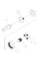
도 2는 본 발명의 회전형 토크 측정장치의 전체 분해 조립도
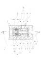
도 3은 본 발명의 회전형 토크 측정장치의 일부 파절 단면 예시도
도 4는 본 발명의 토크변환기어측정수단 분해 조립 예시도
도 5는 본 발명의 기어변환증속수단 분해 조립 예시도
도 6은 본 발명의 측 단면 부분확대 단면 예시도
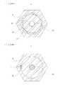
도 7은 도 6의 부분 파절 단면을 나타낸 예시도
도 8은 도 6의 부분 파절 단면을 나타낸 예시도FIG. 1 is a diagram illustrating a preferred embodiment of the present invention
Fig. 2 is an overall exploded view of the rotating torque measuring device of the present invention. Fig.
3 is a partial cross-sectional exemplary view of the rotating torque measuring device of the present invention
4 is an exploded assembly example of the torque conversion gear measuring means of the present invention
Fig. 5 is an exploded assembly example of the gear change-
Fig. 6 is an enlarged sectional side view of a side cross section of the present invention
FIG. 7 is an exemplary view showing a partial fracture section of FIG. 6
8 is an exemplary view showing a partial fracture cross section of Fig. 6
본 발명의 고효율 토크 측정장치는 첨부된 각 도면에 의거 보다 상세히 설명하면 하기와 같다.
The high-efficiency torque measuring apparatus of the present invention will be described in more detail with reference to the accompanying drawings.
즉, 본 발명은 도 1 내지 도 8에서 도시된 봐와 같이, 토크 측정용 하우징(10)의 내부에는, 회전 입력측 샤프트(200)의 일부가 그 중심으로 관통되고, 전측의 일부는 하우징(10)과 상호 걸림 고정되어 있으며, 후측 일부는 워크부(W)에서 인입되는 부하에 대한 전달이 적절히 허용된 고정형 피부하대상체(100)가 설치된 것과;1 to 8, a portion of the
상기 고정형 피부하대상체(100)의 후방에서 그 내부 중심으로는 동력원(M)의 회전동력을 입력받는 회전입력부(210)와 동력전달부(220)를 갖는 회전 입력측 샤프트(200)가 삽입 구성된 것과;A rotary
상기 회전 입력측 샤프트(200) 선측의 동력전달부(220) 끝에는 상기 회전 입력측 샤프트(200)의 회전동력을 후방으로 전달하는 동시에 워크부(W)측에서 부하가 발생될 경우 그 부하가 상기 고정형 피부하대상체(100)에 전적으로 걸리도록 하는 회전 및 역방향 부하전달용 유닛(300)을 설치한 것과;When the load is generated at the workpiece W side while the rotational power of the rotation
상기 회전 및 역방향 부하전달용 유닛(300)의 후측부에는 상기 회전 입력측 샤프트(200)에서부터 전달된 회전동력을 최선 후방의 워크부(W)로 출력하기 위한 회전 출력측 샤프트(500)가 구성된 것; 을 그 특징적 요지로 하였다.
And a rotation
상기한 구성 중 고정형 피부하대상체(100)는, 상기 하우징(10)의 내부에 삽설 구성되고, 중심에는 회전축 관통홈(110)이 뚫려있으며, 일측은 하우징(10)과 결속수단(121)에 의해 고정된 결속고정부(120)가 형성되고, 반대측인 다른 일측에는 비틀림 모멘트에 대한 부하의 전달이 가능한 부하 전달용 기어부(130)가 형성되며, 상기 결속고정부(120)와 부하 전달용 기어부(130) 사이에는 일정한 직경(작은 직경)의 부하걸림부(140)가 형성되고, 상기 부하걸림부(140)의 외주면에는 토크 게측을 위한 스트레인게이지(150)가 부착된 것으로 구성하면 바람직하다.
The fixed skin
상기 회전 및 역방향 부하전달용 유닛(300)은, 상기 회전 입력측 샤프트(200) 후측의 동력전달부(220) 끝에 결합 구성되고, 일측에는 상기 회전 입력측 샤프트(200)와 키이 결합이 된 기어고정판(311)이 구성되며, 상기 기어고정판(311)의 일측면에는 그 중심을 기준으로 일정한 반경 및 등 각도 범위에 다수의 유성기어들(312)을 각각 배치된 제 1 유성기어결합체(310)와;The rotation and reverse
상기 하우징(10)의 내경에 공회전 상태로 삽입되고, 내경에는 상기 고정형 피부하대상체(100)에 형성된 부하 전달용 기어부(130) 및 상기 제 1 유성기어결합체(310)의 유성기어들(312) 외경과 치물림된 내륜 기어(321)가 형성된 부하 연결용 부시형 링기어(320)와;The inner diameter of the
상기 제 1 유성기어결합체(310)에 구성된 유성기어들(312)의 내경에 기어물림된 상태에서 후방으로 일부 더 연장된 선기어(330); 로 이루어진 것으로 구성하면 유리하다.
A
또한, 상기 회전 및 역방향 부하전달용 유닛(300)과 상기 회전 출력측 샤프트(500) 사이에는, 상기 회전 및 역방향 부하전달용 유닛(300)의 동작에 따라 일정한 감속비로 감속된 회전력을 상기 회전 입력측 샤프트에 입력된 처음의 회전비와 동일하게 증감할 수 있도록 하는 회전출력용 증속장치(400)를 추가로 더 설치할 수 있는 데,
A rotating force decelerated at a constant reduction ratio according to the operation of the rotating and counter
상기 회전출력용 증속장치(400)는 다양한 위치와 구조로 설치할 수 있지만, 도면에 도시된 바와 같이,The rotation output
상기 회전 및 역방향 부하전달용 유닛(300)의 제 1 유성기어결합체(310)와 일정한 간격이 유지된 후방에서 상호 대칭으로 구성되고, 후측에는 회전 출력측 샤프트(500)와 키이 결합이 된 기어고정판(411)이 구성되며, 상기 기어고정판(411)의 전측면에는 그 중심을 기준으로 일정한 반경 및 등 각도 범위에 다수의 유성기어들(412)을 각각 배치되고, 상기 유성기어들(412)의 내경에는 상기 선기어(330)의 후측 일부가 기어물림이 된 제 2 유성기어결합체(410)와;The first
상기 제 2 유성기어결합체(410)에 구성되는 유성기어들(412)이 위치한 하우징(10)의 내경에 결합이 되고, 상기 유성기어들(412)과 치물림이 된 내륜기어(421)가 내경에 형성된 비회전형 링기어(420);로 이루어진 구조로 설치하면 아주 이상적일 수 있다.
The
그리고, 상기 회전출력용 증속장치(400)에 속해 있고, 내경에는 상기 유성기어들(412)과 치물림이 된 내륜기어(421)가 형성된 상기 비회전형 링기어(420)는,The
도면에서 예시된 바와 같이 별도로 제작한 다음 상기 하우징(10) 내에 키이 등을 이용해 걸림형으로 조립구성하면 가공의 용이성 측면에서 유리하지만,It is advantageous from the standpoint of easiness of processing if it is separately manufactured as illustrated in the drawing and then assembled into the
때에 따라서는 주물 성형 후 가공으로 이루어지는 하우징(10)의 제작시 그 하우징의 내부에 일체형으로 형성시켜도 무방하다.
The
또, 상기 고정형 피부하대상체(100)의 결속고정부(120)에 구성되어 있는 결속수단(121)은, 다양한 구성이 적용될 수 있지만, 키이, 기어, 스플라인 중 선택된 어느 하나로 걸림 고정을 시키면 아주 무난하다.
Although various constructions can be applied to the binding means 121 constituted in the binding and
또, 상기 고정형 피부하대상체(100)의 회전축 관통홈(110)에 삽입되는 상기 회전 입력측 샤프트(200)의 동력전달부(220)는, 그 회전축 관통홈(110)과 상호 비걸림, 비접촉 상태(일명 공회전 상태)로 삽입되는 것이 요구된다.
The power transmitting
이와 같이 구성될 수 있는 본 발명의 고효율 토크 측정장치는, 전술된 바와 같이 상기 회전 입력측 샤프트(200)에 동력원(M)으로부터 회전동력이 입력되면,
In the high-efficiency torque measuring device of the present invention, which is configured as described above, when the rotational power is input from the power source M to the rotary
그 회전력은 상기 고정형 피부하대상체(100)의 중심에 형성된 관통홈(110)을 관통하는 상기 회전 입력측 샤프트(200)의 동력전달부(220)에 의해 그 후방으로 위치한 상기 회전 및 역방향 부하전달용 유닛(300)과 회전 출력측 샤프트(500)에 전달이 될 수 있음으로 위크부(500)에서 요구되는 일정한 회전동력의 출력이 가능하게 된다.
And the rotational force is transmitted to the fixed-type subcutaneous skin
이때, 상기 위크부(500)에서 일정한 부하가 걸리면, 상기 회전 입력측 샤프트(200)와 회전 출력측 샤프트(500) 사이에는, 상기 회전 입력측 샤프트(200) 후측의 동력전달부(220) 끝에 결합 구성되고, 일측에는 상기 회전 입력측 샤프트(200)와 키이 결합이 된 기어고정판(311)이 구성되며, 상기 기어고정판(311)의 일측면에는 그 중심을 기준으로 일정한 반경 및 등 각도 범위에 다수의 유성기어들(312)을 각각 배치된 제 1 유성기어결합체(310)와;At this time, when a certain load is applied to the
상기 하우징(10)의 내경에 공회전 상태로 삽입되고, 내경에는 상기 고정형 피부하대상체(100)에 형성된 부하 전달용 기어부(130) 및 상기 제 1 유성기어결합체(310)의 유성기어들(312) 외경과 치물림이 된 내륜 기어(321)가 형성된 부하 연결용 부시형 링기어(320)와;The inner diameter of the
상기 제 1 유성기어결합체(310)에 구성된 유성기어들(312)의 내경에 기어물림된 상태에서 후방으로 일부 더 연장된 선기어(330); 로 구성된 상기 회전 및 역방향 부하전달용 유닛(300)이 설치됨에 따라,A
상기 인가된 회전동력에 대하여 후방의 워크부(W) 측으로의 출력 전달(감속된 상태 또는 동일한 회전비로)은 물론 가능하지만,It is possible to transmit the output to the rear workpiece W side (in the decelerated state or the same rotational ratio) with respect to the applied rotational power,
만약, 상기 워크부(W)에 부하가 걸릴 경우에는 상기 회전 및 역방향 부하전달용 유닛(300)의 제 1 유성기어결합체(310)와 부하 연결용 부시형 링기어(320)를 통해,If a load is applied to the work W, the first
하우징에 고정된 상기 고정형 피부하대상체(100)에 모두 걸리는 구조로 되어 있음에 따라,And is fixed to the fixed skin type
워크부(W)에 걸리는 부하에 대한 비틀림 모우멘트인 토크 측정시, 상기 고정형 피부하대상체(100)에 부착된 스트레인게이지(150)로부터 계측된 신호를 아주 간단하게 전송받으면 될 뿐 아니라,The measured signals from the
이의 원인으로 상기 계측된 신호의 전달수단 역시 고정상태의 상기 고정형 피부하대상체(100)에 부착된 스트레인게이지(150)로부터 하우징 외부로 신호연결선 내지 기타 신호 연결부재만 구성하면 됨으로써 아주 간단하고 저렴한 비용으로 설치될 수 있다.As a result of this, the signal transmission line of the fixed signal line can be formed from only the signal line or other signal connection member from the
즉, 기능과 역할은 회전형과 같이 우수하면서도, 토크의 측정과 검출시에는 비회전형과 같이 고정상태의 상기 고정형 피부하대상체(100)로 부터 검출 가능함으로,That is, the function and role are excellent as the rotary type, but can be detected from the stationary skin
결국, 회전형이 갖는 장점과 비회전형이 갖는 장점들만 모두 갖춘 새로운 스타일의 고효율 토크 측정장치로서, 향후 이 분야에서 상당히 유용하게 쓰일 것으로 기대되는 유용한 발명이다.
As a result, it is a new style high-efficiency torque measuring device having both the merits of the rotating type and the advantages of the non-recirculating type, and is a useful invention that is expected to be useful in this field in the future.
게다가, 상기 회전 및 역방향 부하전달용 유닛(300)과 상기 회전 출력측 샤프트(500) 사이에,Further, between the rotary and reverse
상기 회전 및 역방향 부하전달용 유닛(300)의 동작에 따라 일정한 감속비로 감속된 회전력을 상기 회전 입력측 샤프트에 입력된 처음의 회전비와 동일하게 증감할 수 있도록 하는 회전출력용 증속장치(400)를 추가로 더 설치함에 따라 최초에 입력된 회전비와 워크측으로 출력되는 회전비를 동일하게 유지함으로써 더욱더 정밀한 토크검출이 가능하다.
A rotation output accelerator (400) for increasing or decreasing a rotational force decelerated at a constant reduction ratio according to an operation of the rotary and reverse load transfer unit (300) to be equal to the initial rotational ratio inputted to the rotary input side shaft By further installing it, it is possible to detect the torque more precisely by keeping the rotation rate inputted first and the rotation rate outputted to the work side the same.
M: 동력원W: 워크부
10: 하우징100: 피부하대상체
110: 관통홈120: 결속고정부
121: 결속수단130: 기어부
140: 부하걸림부150: 스트레인게이지
200: 회전 입력측 샤프트210: 회전입력부
220: 동력전달부300: 유닛
310: 제 1 유성기어결합체311: 기어고정판
312: 유성기어들320: 링기어
321: 내륜 기어330: 선기어
400: 증속장치410: 제 2 유성기어결합체
411: 기어고정판412: 유성기어들
420: 링기어421: 내륜기어
500: 샤프트M: Power source W: Workpiece
10: housing 100: skin lower body
110: penetrating groove 120:
121: Coupling means 130:
140: Load catching part 150: Strain gauge
200: rotation input side shaft 210: rotation input section
220: Power transmission unit 300: Unit
310: first planetary gear assemblies 311: gear fixing plates
312: planetary gears 320: ring gear
321: Inner ring gear 330: Sun gear
400: speed increasing device 410: second planetary gear combination
411: Gear fixing plate 412: Planetary gears
420: ring gear 421: inner ring gear
500: Shaft
Claims (8)
Translated fromKorean상기 고정형 피부하대상체(100)의 후방에서 그 내부 중심으로는 동력원(M)의 회전동력을 입력받는 회전입력부(210)와 동력전달부(220)를 갖는 회전 입력측 샤프트(200)가 삽입 구성된 것과;
상기 회전 입력측 샤프트(200) 선측의 동력전달부(220) 끝에는 상기 회전 입력측 샤프트(200)의 회전동력을 후방으로 전달하는 동시에 워크부(W)측에서 부하가 발생될 경우 그 부하가 상기 고정형 피부하대상체(100)에 전적으로 걸리도록 하는 회전 및 역방향 부하전달용 유닛(300)을 설치한 것과;
상기 회전 및 역방향 부하전달용 유닛(300)의 후측부에는 상기 회전 입력측 샤프트(200)에서부터 전달된 회전동력을 최선 후방의 워크부(W)로 출력하기 위한 회전 출력측 샤프트(500)가 구성된 것과;
상기 고정형 피부하대상체(100)는,
상기 하우징(10)의 내부에 삽설 구성되고, 중심에는 회전축 관통홈(110)이 뚫려있으며, 일측은 하우징(10)과 결속수단(121)에 의해 고정된 결속고정부(120)가 형성되고, 반대측인 다른 일측에는 비틀림 모멘트에 대한 부하의 전달이 가능한 부하 전달용 기어부(130)가 형성되며, 상기 결속고정부(120)와 부하 전달용 기어부(130) 사이에는 일정한 직경(작은 직경)의 부하걸림부(140)가 형성되고, 상기 부하걸림부(140)의 외주면에는 토크 게측을 위한 스트레인게이지(150)가 부착된 것을 포함하는 것을 특징으로 한 고효율 토크 측정장치.
A part of the front side of the shaft is engaged with and fixed to the housing 10 while a part of the rear side of the torque measuring housing 10 is fixed to the workpiece W A fixed skin lower body 100 in which the delivery to the incoming load is appropriately permitted is provided;
A rotary input side shaft 200 having a rotation input portion 210 and a power transmission portion 220 for receiving the rotational power of the power source M is inserted into the inner center of the fixed skin lower body 100, ;
When the load is generated at the workpiece W side while the rotational power of the rotation input side shaft 200 is transmitted to the end of the power transmission portion 220 on the side of the rotation input side shaft 200, And a unit 300 for rotating and reversing load to be completely engaged with the lower body 100;
A rotation output side shaft 500 for outputting the rotational power transmitted from the rotation input side shaft 200 to the workpiece W at the rearmost position is formed on the rear side of the rotation and reverse direction load transfer unit 300;
The fixed skin lower body (100)
A coupling shaft 120 is formed at one side of the housing 10 and is fixed by a coupling unit 121. The coupling unit 120 is fixed to the housing 10, (Small diameter) is formed between the coupling and fixing part 120 and the load transmission gear part 130. The load transmitting gear part 130 is formed on the other side, And a strain gauge (150) for a torque exciter is attached to an outer circumferential surface of the load engaging portion (140).
상기 회전 및 역방향 부하전달용 유닛(300)과 상기 회전 출력측 샤프트(500) 사이에는, 상기 회전 및 역방향 부하전달용 유닛(300)의 동작에 따라 일정한 감속비로 감속된 회전력을 상기 회전 입력측 샤프트에 입력된 처음의 회전비와 동일하게 증감할 수 있도록 하는 회전출력용 증속장치(400)를 추가로 더 설치할 수 있는 것과;
상기 회전출력용 증속장치(400)는,
상기 회전 및 역방향 부하전달용 유닛(300)의 제 1 유성기어결합체(310)와 일정한 간격이 유지된 후방에서 상호 대칭으로 구성되고, 후측에는 회전 출력측 샤프트(500)와 키이 결합이 된 기어고정판(411)이 구성되며, 상기 기어고정판(411)의 전측면에는 그 중심을 기준으로 일정한 반경 및 등 각도 범위에 다수의 유성기어들(412)을 각각 배치되고, 상기 유성기어들(412)의 내경에는 상기 선기어(330)의 후측 일부가 기어물림이 된 제 2 유성기어결합체(410)와;
상기 제 2 유성기어결합체(410)에 구성되는 유성기어들(412)이 위치한 하우징(10)의 내경에 결합이 되고, 상기 유성기어들(412)과 치물림이 된 내륜기어(421)가 내경에 형성된 비회전형 링기어(420)으로 이루어진 것과;
상기 회전출력용 증속장치(400)에 속해 있고, 내경에는 상기 유성기어들(412)과 치물림이 된 내륜기어(421)가 형성된 상기 비회전형 링기어(420)는,
별도로 제작한 다음 하우징(10) 내에 걸림형으로 조립구성하거나, 또는 상기 하우징(10)의 제작시 그 내부에 일체로 형성될 수 있는 것을 특징으로 한 고효율 토크 측정장치.
The method according to claim 1,
A rotational force decelerated at a constant reduction ratio according to the operation of the rotational and reverse load transfer unit 300 is input to the rotational input side shaft between the rotational and reverse load transfer unit 300 and the rotational output side shaft 500 Which can increase / decrease the same as the initial rotation ratio of the rotation output;
The rotation output speed increasing device (400)
The first planetary gear combination 310 and the first planetary gear combination 310 of the rotary and reverse load transfer unit 300 are symmetrically arranged at a predetermined distance from the rear of the first planetary gear combination 310, A plurality of planetary gears 412 are disposed on a front surface of the gear fixing plate 411 in a predetermined radius and a constant angle range with respect to a center of the planetary gears 411, A second planetary gear combination (410) having a rear portion of the sun gear (330) gear engaged;
The inner ring gear 421 engaged with the planetary gears 412 is engaged with the inner diameter of the housing 10 in which the planetary gears 412 of the second planetary gear assembly 410 are located, And a non-recirculating ring gear 420 formed on the ring gear 420;
The non-recirculating ring gear 420, which belongs to the speed-output speed-increasing device 400 and has an inner ring gear 421 which is engaged with the planetary gears 412 on the inner diameter,
And can be integrally formed inside the housing (10) when the housing (10) is manufactured. The high efficiency torque measuring device according to claim 1, wherein the housing (10)
상기 고정형 피부하대상체(100)의 결속고정부(120)에 구성되어 있는 결속수단(121)은,
키이 또는 기어 또는 스플라인 중 선택된 어느 하나로 걸림, 고정상태로 구성될 수 있는 것을 특징으로 한 고효율 토크 측정장치.The method according to claim 1,
The binding means 121, which is formed in the binding and fixing unit 120 of the fixed skin lower body 100,
Wherein the engaging member can be configured to be engaged with a selected one of a key, a gear, and a spline, or in a fixed state.
Priority Applications (1)
| Application Number | Priority Date | Filing Date | Title |
|---|---|---|---|
| KR1020120118814AKR101391153B1 (en) | 2012-10-25 | 2012-10-25 | High-efficiency torque measuring device |
Applications Claiming Priority (1)
| Application Number | Priority Date | Filing Date | Title |
|---|---|---|---|
| KR1020120118814AKR101391153B1 (en) | 2012-10-25 | 2012-10-25 | High-efficiency torque measuring device |
Publications (1)
| Publication Number | Publication Date |
|---|---|
| KR101391153B1true KR101391153B1 (en) | 2014-05-27 |
Family
ID=50892990
Family Applications (1)
| Application Number | Title | Priority Date | Filing Date |
|---|---|---|---|
| KR1020120118814AExpired - Fee RelatedKR101391153B1 (en) | 2012-10-25 | 2012-10-25 | High-efficiency torque measuring device |
Country Status (1)
| Country | Link |
|---|---|
| KR (1) | KR101391153B1 (en) |
Cited By (1)
| Publication number | Priority date | Publication date | Assignee | Title |
|---|---|---|---|---|
| KR102042134B1 (en)* | 2016-11-30 | 2019-11-07 | 프로드라이브 앤 모션 컴퍼니 리미티드 | Axial rotation type torque sensor |
Citations (3)
| Publication number | Priority date | Publication date | Assignee | Title |
|---|---|---|---|---|
| KR20000003297U (en)* | 1998-07-22 | 2000-02-15 | 하용수 | wrench |
| JP2002513889A (en) | 1998-01-12 | 2002-05-14 | ピーター, ジェームス ミルナー, | Rolling contact continuously variable transmission |
| KR20090096235A (en)* | 2008-03-07 | 2009-09-10 | 엘에스전선 주식회사 | Non-Contacting Torque Sensor For Measuring Twisting Angle and Absolute Angle |
- 2012
- 2012-10-25KRKR1020120118814Apatent/KR101391153B1/ennot_activeExpired - Fee Related
Patent Citations (3)
| Publication number | Priority date | Publication date | Assignee | Title |
|---|---|---|---|---|
| JP2002513889A (en) | 1998-01-12 | 2002-05-14 | ピーター, ジェームス ミルナー, | Rolling contact continuously variable transmission |
| KR20000003297U (en)* | 1998-07-22 | 2000-02-15 | 하용수 | wrench |
| KR20090096235A (en)* | 2008-03-07 | 2009-09-10 | 엘에스전선 주식회사 | Non-Contacting Torque Sensor For Measuring Twisting Angle and Absolute Angle |
Cited By (1)
| Publication number | Priority date | Publication date | Assignee | Title |
|---|---|---|---|---|
| KR102042134B1 (en)* | 2016-11-30 | 2019-11-07 | 프로드라이브 앤 모션 컴퍼니 리미티드 | Axial rotation type torque sensor |
Similar Documents
| Publication | Publication Date | Title |
|---|---|---|
| EP3309419A3 (en) | Rotation transmission device | |
| US10308314B2 (en) | Central shaft torque sensing for electric bicycle having centre-mounted motor | |
| US7591195B2 (en) | Optical torque sensor | |
| US10711854B2 (en) | Clutch device and motor unit using said clutch device | |
| CN103697085B (en) | Dual one-way clutch combination bearing | |
| EP2261631A4 (en) | Method of detecting amount of axis displacement in driving force transmission mechanism using automatic self-aligning engagement clutch | |
| US20070039415A1 (en) | Rotary indexing table | |
| EP2604388A3 (en) | Power tool with force sensing electronic clutch | |
| KR101391153B1 (en) | High-efficiency torque measuring device | |
| US20050282678A1 (en) | Gearbox torsional load sensor | |
| US20190265116A1 (en) | Torque detection device | |
| DE50107858D1 (en) | PRESSURE MEASURING DEVICE | |
| CN100494935C (en) | Direct torque sensor | |
| CN211553160U (en) | Push-pull force dynamometer | |
| EP3105074B1 (en) | Pto shaft monitoring apparatus | |
| JP2010223252A (en) | Position detecting device and belt-type continuously variable transmission equipped with the same | |
| JP2018194160A (en) | Power transmission device and crushing device | |
| CN104896019A (en) | Gear transmission device for stacking robot | |
| KR20120109367A (en) | Rotation state detecting apparatus | |
| CN201034761Y (en) | Direct-sensing type torque sensor | |
| KR101932820B1 (en) | Torque detecting device | |
| US20030089181A1 (en) | Device for measuring torque and the direction of rotation in a drive assembly | |
| CN109790918B (en) | Transmission with torque measuring device | |
| CN210830379U (en) | Speed reducer protection device for rotary filter screen | |
| KR100583258B1 (en) | Reducer displaying power with torque meter |
Legal Events
| Date | Code | Title | Description |
|---|---|---|---|
| A201 | Request for examination | ||
| PA0109 | Patent application | St.27 status event code:A-0-1-A10-A12-nap-PA0109 | |
| PA0201 | Request for examination | St.27 status event code:A-1-2-D10-D11-exm-PA0201 | |
| P11-X000 | Amendment of application requested | St.27 status event code:A-2-2-P10-P11-nap-X000 | |
| P13-X000 | Application amended | St.27 status event code:A-2-2-P10-P13-nap-X000 | |
| D13-X000 | Search requested | St.27 status event code:A-1-2-D10-D13-srh-X000 | |
| D14-X000 | Search report completed | St.27 status event code:A-1-2-D10-D14-srh-X000 | |
| E902 | Notification of reason for refusal | ||
| PE0902 | Notice of grounds for rejection | St.27 status event code:A-1-2-D10-D21-exm-PE0902 | |
| E13-X000 | Pre-grant limitation requested | St.27 status event code:A-2-3-E10-E13-lim-X000 | |
| P11-X000 | Amendment of application requested | St.27 status event code:A-2-2-P10-P11-nap-X000 | |
| P13-X000 | Application amended | St.27 status event code:A-2-2-P10-P13-nap-X000 | |
| T11-X000 | Administrative time limit extension requested | St.27 status event code:U-3-3-T10-T11-oth-X000 | |
| E701 | Decision to grant or registration of patent right | ||
| PE0701 | Decision of registration | St.27 status event code:A-1-2-D10-D22-exm-PE0701 | |
| GRNT | Written decision to grant | ||
| PR0701 | Registration of establishment | St.27 status event code:A-2-4-F10-F11-exm-PR0701 | |
| PR1002 | Payment of registration fee | St.27 status event code:A-2-2-U10-U11-oth-PR1002 Fee payment year number:1 | |
| R18-X000 | Changes to party contact information recorded | St.27 status event code:A-5-5-R10-R18-oth-X000 | |
| PG1601 | Publication of registration | St.27 status event code:A-4-4-Q10-Q13-nap-PG1601 | |
| P22-X000 | Classification modified | St.27 status event code:A-4-4-P10-P22-nap-X000 | |
| FPAY | Annual fee payment | Payment date:20170425 Year of fee payment:4 | |
| PR1001 | Payment of annual fee | St.27 status event code:A-4-4-U10-U11-oth-PR1001 Fee payment year number:4 | |
| FPAY | Annual fee payment | Payment date:20180316 Year of fee payment:5 | |
| PR1001 | Payment of annual fee | St.27 status event code:A-4-4-U10-U11-oth-PR1001 Fee payment year number:5 | |
| LAPS | Lapse due to unpaid annual fee | ||
| PC1903 | Unpaid annual fee | St.27 status event code:A-4-4-U10-U13-oth-PC1903 Not in force date:20190426 Payment event data comment text:Termination Category : DEFAULT_OF_REGISTRATION_FEE | |
| PC1903 | Unpaid annual fee | St.27 status event code:N-4-6-H10-H13-oth-PC1903 Ip right cessation event data comment text:Termination Category : DEFAULT_OF_REGISTRATION_FEE Not in force date:20190426 | |
| PN2301 | Change of applicant | St.27 status event code:A-5-5-R10-R13-asn-PN2301 St.27 status event code:A-5-5-R10-R11-asn-PN2301 |