KR101386971B1 - Process and apparatus for a wavelength tunning source - Google Patents
Process and apparatus for a wavelength tunning sourceDownload PDFInfo
- Publication number
- KR101386971B1 KR101386971B1KR1020057023416AKR20057023416AKR101386971B1KR 101386971 B1KR101386971 B1KR 101386971B1KR 1020057023416 AKR1020057023416 AKR 1020057023416AKR 20057023416 AKR20057023416 AKR 20057023416AKR 101386971 B1KR101386971 B1KR 101386971B1
- Authority
- KR
- South Korea
- Prior art keywords
- delete delete
- electromagnetic radiation
- components
- optical
- arrangement
- Prior art date
- Legal status (The legal status is an assumption and is not a legal conclusion. Google has not performed a legal analysis and makes no representation as to the accuracy of the status listed.)
- Expired - Lifetime
Links
Images


Classifications
- G—PHYSICS
- G01—MEASURING; TESTING
- G01J—MEASUREMENT OF INTENSITY, VELOCITY, SPECTRAL CONTENT, POLARISATION, PHASE OR PULSE CHARACTERISTICS OF INFRARED, VISIBLE OR ULTRAVIOLET LIGHT; COLORIMETRY; RADIATION PYROMETRY
- G01J3/00—Spectrometry; Spectrophotometry; Monochromators; Measuring colours
- G01J3/02—Details
- G01J3/10—Arrangements of light sources specially adapted for spectrometry or colorimetry
- A—HUMAN NECESSITIES
- A61—MEDICAL OR VETERINARY SCIENCE; HYGIENE
- A61B—DIAGNOSIS; SURGERY; IDENTIFICATION
- A61B5/00—Measuring for diagnostic purposes; Identification of persons
- A—HUMAN NECESSITIES
- A61—MEDICAL OR VETERINARY SCIENCE; HYGIENE
- A61B—DIAGNOSIS; SURGERY; IDENTIFICATION
- A61B5/00—Measuring for diagnostic purposes; Identification of persons
- A61B5/0059—Measuring for diagnostic purposes; Identification of persons using light, e.g. diagnosis by transillumination, diascopy, fluorescence
- A61B5/0062—Arrangements for scanning
- A61B5/0066—Optical coherence imaging
- G—PHYSICS
- G01—MEASURING; TESTING
- G01B—MEASURING LENGTH, THICKNESS OR SIMILAR LINEAR DIMENSIONS; MEASURING ANGLES; MEASURING AREAS; MEASURING IRREGULARITIES OF SURFACES OR CONTOURS
- G01B9/00—Measuring instruments characterised by the use of optical techniques
- G01B9/02—Interferometers
- G01B9/02001—Interferometers characterised by controlling or generating intrinsic radiation properties
- G01B9/02002—Interferometers characterised by controlling or generating intrinsic radiation properties using two or more frequencies
- G01B9/02004—Interferometers characterised by controlling or generating intrinsic radiation properties using two or more frequencies using frequency scans
- G—PHYSICS
- G01—MEASURING; TESTING
- G01B—MEASURING LENGTH, THICKNESS OR SIMILAR LINEAR DIMENSIONS; MEASURING ANGLES; MEASURING AREAS; MEASURING IRREGULARITIES OF SURFACES OR CONTOURS
- G01B9/00—Measuring instruments characterised by the use of optical techniques
- G01B9/02—Interferometers
- G01B9/0209—Low-coherence interferometers
- G01B9/02091—Tomographic interferometers, e.g. based on optical coherence
- G—PHYSICS
- G01—MEASURING; TESTING
- G01J—MEASUREMENT OF INTENSITY, VELOCITY, SPECTRAL CONTENT, POLARISATION, PHASE OR PULSE CHARACTERISTICS OF INFRARED, VISIBLE OR ULTRAVIOLET LIGHT; COLORIMETRY; RADIATION PYROMETRY
- G01J3/00—Spectrometry; Spectrophotometry; Monochromators; Measuring colours
- G01J3/12—Generating the spectrum; Monochromators
- G—PHYSICS
- G01—MEASURING; TESTING
- G01J—MEASUREMENT OF INTENSITY, VELOCITY, SPECTRAL CONTENT, POLARISATION, PHASE OR PULSE CHARACTERISTICS OF INFRARED, VISIBLE OR ULTRAVIOLET LIGHT; COLORIMETRY; RADIATION PYROMETRY
- G01J9/00—Measuring optical phase difference; Determining degree of coherence; Measuring optical wavelength
- G01J9/02—Measuring optical phase difference; Determining degree of coherence; Measuring optical wavelength by interferometric methods
- G—PHYSICS
- G01—MEASURING; TESTING
- G01N—INVESTIGATING OR ANALYSING MATERIALS BY DETERMINING THEIR CHEMICAL OR PHYSICAL PROPERTIES
- G01N21/00—Investigating or analysing materials by the use of optical means, i.e. using sub-millimetre waves, infrared, visible or ultraviolet light
- G01N21/17—Systems in which incident light is modified in accordance with the properties of the material investigated
- G01N21/47—Scattering, i.e. diffuse reflection
- G01N21/4795—Scattering, i.e. diffuse reflection spatially resolved investigating of object in scattering medium
- G—PHYSICS
- G02—OPTICS
- G02B—OPTICAL ELEMENTS, SYSTEMS OR APPARATUS
- G02B27/00—Optical systems or apparatus not provided for by any of the groups G02B1/00 - G02B26/00, G02B30/00
- G02B27/42—Diffraction optics, i.e. systems including a diffractive element being designed for providing a diffractive effect
- G02B27/46—Systems using spatial filters
- G—PHYSICS
- G02—OPTICS
- G02B—OPTICAL ELEMENTS, SYSTEMS OR APPARATUS
- G02B27/00—Optical systems or apparatus not provided for by any of the groups G02B1/00 - G02B26/00, G02B30/00
- G02B27/48—Laser speckle optics
- G—PHYSICS
- G02—OPTICS
- G02B—OPTICAL ELEMENTS, SYSTEMS OR APPARATUS
- G02B5/00—Optical elements other than lenses
- G02B5/20—Filters
- G—PHYSICS
- G01—MEASURING; TESTING
- G01J—MEASUREMENT OF INTENSITY, VELOCITY, SPECTRAL CONTENT, POLARISATION, PHASE OR PULSE CHARACTERISTICS OF INFRARED, VISIBLE OR ULTRAVIOLET LIGHT; COLORIMETRY; RADIATION PYROMETRY
- G01J9/00—Measuring optical phase difference; Determining degree of coherence; Measuring optical wavelength
- G01J9/02—Measuring optical phase difference; Determining degree of coherence; Measuring optical wavelength by interferometric methods
- G01J9/0215—Measuring optical phase difference; Determining degree of coherence; Measuring optical wavelength by interferometric methods by shearing interferometric methods
- H—ELECTRICITY
- H01—ELECTRIC ELEMENTS
- H01S—DEVICES USING THE PROCESS OF LIGHT AMPLIFICATION BY STIMULATED EMISSION OF RADIATION [LASER] TO AMPLIFY OR GENERATE LIGHT; DEVICES USING STIMULATED EMISSION OF ELECTROMAGNETIC RADIATION IN WAVE RANGES OTHER THAN OPTICAL
- H01S3/00—Lasers, i.e. devices using stimulated emission of electromagnetic radiation in the infrared, visible or ultraviolet wave range
- H01S3/05—Construction or shape of optical resonators; Accommodation of active medium therein; Shape of active medium
- H01S3/08—Construction or shape of optical resonators or components thereof
- H01S3/08004—Construction or shape of optical resonators or components thereof incorporating a dispersive element, e.g. a prism for wavelength selection
- H01S3/08009—Construction or shape of optical resonators or components thereof incorporating a dispersive element, e.g. a prism for wavelength selection using a diffraction grating
- H—ELECTRICITY
- H01—ELECTRIC ELEMENTS
- H01S—DEVICES USING THE PROCESS OF LIGHT AMPLIFICATION BY STIMULATED EMISSION OF RADIATION [LASER] TO AMPLIFY OR GENERATE LIGHT; DEVICES USING STIMULATED EMISSION OF ELECTROMAGNETIC RADIATION IN WAVE RANGES OTHER THAN OPTICAL
- H01S3/00—Lasers, i.e. devices using stimulated emission of electromagnetic radiation in the infrared, visible or ultraviolet wave range
- H01S3/05—Construction or shape of optical resonators; Accommodation of active medium therein; Shape of active medium
- H01S3/08—Construction or shape of optical resonators or components thereof
- H01S3/08059—Constructional details of the reflector, e.g. shape
- H01S3/08063—Graded reflectivity, e.g. variable reflectivity mirror
- H—ELECTRICITY
- H01—ELECTRIC ELEMENTS
- H01S—DEVICES USING THE PROCESS OF LIGHT AMPLIFICATION BY STIMULATED EMISSION OF RADIATION [LASER] TO AMPLIFY OR GENERATE LIGHT; DEVICES USING STIMULATED EMISSION OF ELECTROMAGNETIC RADIATION IN WAVE RANGES OTHER THAN OPTICAL
- H01S3/00—Lasers, i.e. devices using stimulated emission of electromagnetic radiation in the infrared, visible or ultraviolet wave range
- H01S3/10—Controlling the intensity, frequency, phase, polarisation or direction of the emitted radiation, e.g. switching, gating, modulating or demodulating
- H01S3/105—Controlling the intensity, frequency, phase, polarisation or direction of the emitted radiation, e.g. switching, gating, modulating or demodulating by controlling the mutual position or the reflecting properties of the reflectors of the cavity, e.g. by controlling the cavity length
- H—ELECTRICITY
- H01—ELECTRIC ELEMENTS
- H01S—DEVICES USING THE PROCESS OF LIGHT AMPLIFICATION BY STIMULATED EMISSION OF RADIATION [LASER] TO AMPLIFY OR GENERATE LIGHT; DEVICES USING STIMULATED EMISSION OF ELECTROMAGNETIC RADIATION IN WAVE RANGES OTHER THAN OPTICAL
- H01S5/00—Semiconductor lasers
- H01S5/10—Construction or shape of the optical resonator, e.g. extended or external cavity, coupled cavities, bent-guide, varying width, thickness or composition of the active region
- H01S5/14—External cavity lasers
- H01S5/141—External cavity lasers using a wavelength selective device, e.g. a grating or etalon
- H—ELECTRICITY
- H01—ELECTRIC ELEMENTS
- H01S—DEVICES USING THE PROCESS OF LIGHT AMPLIFICATION BY STIMULATED EMISSION OF RADIATION [LASER] TO AMPLIFY OR GENERATE LIGHT; DEVICES USING STIMULATED EMISSION OF ELECTROMAGNETIC RADIATION IN WAVE RANGES OTHER THAN OPTICAL
- H01S5/00—Semiconductor lasers
- H01S5/10—Construction or shape of the optical resonator, e.g. extended or external cavity, coupled cavities, bent-guide, varying width, thickness or composition of the active region
- H01S5/14—External cavity lasers
- H01S5/146—External cavity lasers using a fiber as external cavity
- H—ELECTRICITY
- H01—ELECTRIC ELEMENTS
- H01S—DEVICES USING THE PROCESS OF LIGHT AMPLIFICATION BY STIMULATED EMISSION OF RADIATION [LASER] TO AMPLIFY OR GENERATE LIGHT; DEVICES USING STIMULATED EMISSION OF ELECTROMAGNETIC RADIATION IN WAVE RANGES OTHER THAN OPTICAL
- H01S5/00—Semiconductor lasers
- H01S5/40—Arrangement of two or more semiconductor lasers, not provided for in groups H01S5/02 - H01S5/30
- H01S5/4025—Array arrangements, e.g. constituted by discrete laser diodes or laser bar
- H01S5/4087—Array arrangements, e.g. constituted by discrete laser diodes or laser bar emitting more than one wavelength
Landscapes
- Physics & Mathematics (AREA)
- Health & Medical Sciences (AREA)
- Life Sciences & Earth Sciences (AREA)
- General Physics & Mathematics (AREA)
- Spectroscopy & Molecular Physics (AREA)
- General Health & Medical Sciences (AREA)
- Pathology (AREA)
- Optics & Photonics (AREA)
- Heart & Thoracic Surgery (AREA)
- Medical Informatics (AREA)
- Molecular Biology (AREA)
- Surgery (AREA)
- Animal Behavior & Ethology (AREA)
- Biomedical Technology (AREA)
- Public Health (AREA)
- Veterinary Medicine (AREA)
- Engineering & Computer Science (AREA)
- Biophysics (AREA)
- Radiology & Medical Imaging (AREA)
- Nuclear Medicine, Radiotherapy & Molecular Imaging (AREA)
- Chemical & Material Sciences (AREA)
- Analytical Chemistry (AREA)
- Biochemistry (AREA)
- Immunology (AREA)
- Semiconductor Lasers (AREA)
- Lasers (AREA)
- Optical Modulation, Optical Deflection, Nonlinear Optics, Optical Demodulation, Optical Logic Elements (AREA)
- Spectrometry And Color Measurement (AREA)
- Microscoopes, Condenser (AREA)
- Investigating Or Analysing Materials By Optical Means (AREA)
- Optical Communication System (AREA)
- Liquid Crystal (AREA)
- Investigating, Analyzing Materials By Fluorescence Or Luminescence (AREA)
- Measurement And Recording Of Electrical Phenomena And Electrical Characteristics Of The Living Body (AREA)
- Discharge Lamps And Accessories Thereof (AREA)
Abstract
Translated fromKorean
Description
Translated fromKorean본 출원은 2003년 6월 6일자로 출원된 미국 특허출원번호 제60/476,600호에 대한 우선권을 주장하며, 그 전체적 개시 내용은 참조로서 본 발명에 포함된다.This application claims the benefit of US patent application Ser. No. 60 / 476,600, filed June 6, 2003, the entire disclosure of which is incorporated herein by reference.
본 출원은 일반적으로 광학적 시스템에 관한 것이며, 특히 파장 동조용 광파장 필터 시스템에 관한 것이다.The present application relates generally to optical systems, and more particularly to optical wavelength filter systems for wavelength tuning.
광 반사측정(optical reflectometry), 생의학(biomedical) 영상화, 센서 인테로게이션(sensor interrogation) 및 테스트 및 측정을 위해 빠르면서 광범위하게 동조 가능한 파장 레이저 소스를 개발하기 위한 상당한 노력이 기울여지고 있다. 공동내(intra-cavity) 협대역 파장 스캐닝 필터를 사용함으로써 좁은 선폭, 넓은 범위 및 빠른 동조가 얻어진다. 모드 호핑(mode-hopping) 없는 단일 주파수 작동은 확장 공동(extended-cavity) 반도체 레이저에서 회절 격자 필터 설계를 사용하여 실증되고 있다. 그러나, 단일 주파수 레이저 동작을 실현하고 모드 호핑 없는 동조를 보장하기 위해서, 복잡한 기계 장치를 사용하며 최대 동조 속도를 제한할 수 있다. 지금까지 실증된 최고속 동조 속도의 하나는 10nm/s 미만으로 제한되고 있다. 생의학 영상화와 같은 특정 응용에서, 10 GHz 이상의 순간 선폭에 대응하는 다중 종축 모드 작동이 충분할 수 있다. 이러한 폭은 광학 결맞음 단층촬영기에서 수 밀리미터의 조직 내 사정 깊이(ranging depth)와 스펙트럼 부호화 공초점 현미경(spectrally encoded confocal microscopy)에서 마이크로미터 수준의 횡(transverse) 해상도를 제공할 수 있다.Considerable efforts are being made to develop fast and widely tunable wavelength laser sources for optical reflectometry, biomedical imaging, sensor interrogation, and test and measurement. By using an intra-cavity narrowband wavelength scanning filter, narrow linewidth, wide range and fast tuning are obtained. Single frequency operation without mode-hopping has been demonstrated using diffraction grating filter designs in extended-cavity semiconductor lasers. However, in order to realize single frequency laser operation and to ensure tuning without mode hopping, complex mechanical devices can be used and the maximum tuning speed can be limited. One of the fastest tuning speeds demonstrated so far is limited to less than 10 nm / s. In certain applications, such as biomedical imaging, multiple longitudinal mode operation corresponding to instantaneous linewidths above 10 GHz may be sufficient. This width can provide micrometer-level transverse resolution in a few millimeters of ranging depth in optical coherence tomography and in spectrally encoded confocal microscopy.
10 GHz 정도의 선폭은 공동내 동조 요소(음향 광필터(acousto-optic filter), 패브리-페로 필터 및 검류계 구동형 회절 격자 필터와 같은)를 사용하여 용이하게 달성될 수 있다. 그러나, 이미 실증된 스위프 주파수는 필터의 유한한 동조 속도에 의해 제한된 1 kHz 미만이다. 생의학 응용에서 (초당 30프레임을 초과하는) 비디오급(video-rate) 고해상도 광영상을 위해서는 15 kHz보다 큰 반복률을 갖는 고속 동조가 필요할 수 있다.Line widths on the order of 10 GHz can be readily achieved using intracavity tuning elements (such as acoustic-optic filters, Fabry-Perot filters and galvanometer driven diffraction grating filters). However, the already demonstrated sweep frequency is less than 1 kHz, limited by the finite tuning speed of the filter. In biomedical applications, high-speed tuning with repetition rates greater than 15 kHz may be required for video-rate high-resolution optical images (greater than 30 frames per second).
따라서, 전술한 결함을 극복할 필요가 있다.Therefore, there is a need to overcome the above-mentioned defects.
본 발명의 예시적인 개념에 따라, 넓은 스펙트럼 범위에 걸쳐 15kHz보다 큰 반복률로 동조될 수 있는 광파장 필터가 제공될 수 있다. 또한, 레이저 이득 매체에 결합된 이러한 광학 필터를 포함하는 파장 동조 소스가 제공될 수 있다. 동조 소스는 광학 결맞음 단층촬영기 및 스펙트럼 부호화 공초점 현미경과 같은 비디오급 광학 영상 응용에 유용할 수 있다.In accordance with an exemplary concept of the present invention, an optical wavelength filter can be provided that can be tuned at a repetition rate greater than 15 kHz over a wide spectral range. In addition, a wavelength tuning source comprising such an optical filter coupled to the laser gain medium can be provided. Tuning sources can be useful for video-grade optical imaging applications such as optical coherence tomography and spectral coded confocal microscopy.
일반적으로, 본 발명의 예시적인 실시예에 따른 광필터는 회절 격자, 회전 다각 스캐너 및 망원경을 포함할 수 있다. 이러한 광학 필터는 통상적인 필터보다 한 차수 이상 빠른 크기를 갖는 동조 속도로 작동될 수 있다. 파장 동조 가능 광원은 예를 들어 레이저 이득 매체와 결합된 필터를 사용함으로써 구현될 수 있다. 필터와 이득 매체는 레이저 공동 내로 더 포함될 수 있다. 예를 들어, 레이저는 그 중심 파장이 높은 반복률로 넓은 파장 범위에 걸쳐 스위프(sweep)됨과 동시에 협대역 스펙트럼을 방출할 수 있다.In general, an optical filter in accordance with an exemplary embodiment of the present invention may include a diffraction grating, a rotating polygon scanner, and a telescope. Such an optical filter can be operated at a tuning speed having a magnitude more than one order faster than conventional filters. The wavelength tunable light source can be implemented, for example, by using a filter combined with a laser gain medium. The filter and gain medium may further be incorporated into the laser cavity. For example, a laser can emit a narrowband spectrum while its center wavelength is swept over a wide wavelength range at high repetition rates.
본 발명의 예시적인 실시예에서, 시간이 지남에 따라 평균 주파수가 실질적으로 연속적으로 변하는 스펙트럼을 구비하는 전자기 복사를 방출하는 배열을 포함하는 장치가 제공된다. 이러한 전자기 복사는 밀리초 당 100 테라헤르츠보다 큰 동조 속도와 관련될 수 있다. 평균 주파수는 5 킬로헤르츠보다 큰 반복률로 또는 10 테라헤르츠보다 큰 범위에 걸쳐 반복적으로 변화될 수 있다. 스펙트럼은 가시광 파장, 근적외선 파장 또는 적외선 파장의 일부를 포함하는 동조 범위를 가질 수 있다. 예시적인 스펙트럼은 대략 850nm, 1300nm 또는 1700nm인 파장에서 중심 설정될 수 있다. 또한, 스펙트럼은 100 기가헤르츠보다 작은 순간 선폭을 가질 수 있다. 장치는 또한 5m보다 짧은 왕복 트립(round trip) 길이를 갖는 레이저 공동을 포함할 수도 있다. 장치는 또한 방출된 전자기 복사의 적어도 일부를 수신하여 그 일부를 더 먼 위치로 반사 또는 편향시키도록 구성될 수 있는 다각 스캐너 배열을 구비할 수도 있다. 또한, 전자기 복사의 성분들을 선택적으로 수신하는 빔 분리 배열이 제공될 수 있다.In an exemplary embodiment of the invention, an apparatus is provided that includes an arrangement that emits electromagnetic radiation having a spectrum in which the average frequency changes substantially continuously over time. Such electromagnetic radiation can be associated with tuning speeds greater than 100 terahertz per millisecond. The average frequency can be changed repeatedly at repetition rates greater than 5 kilohertz or over a range greater than 10 terahertz. The spectrum may have a tuning range that includes part of the visible light wavelength, the near infrared wavelength or the infrared wavelength. Exemplary spectra can be centered at wavelengths that are approximately 850 nm, 1300 nm or 1700 nm. In addition, the spectrum can have an instantaneous linewidth of less than 100 gigahertz. The apparatus may also include a laser cavity having a round trip length of less than 5 m. The apparatus may also have a multi-faceted scanner arrangement that can be configured to receive at least a portion of the emitted electromagnetic radiation and reflect or deflect the portion to a distant location. In addition, a beam separation arrangement may be provided that selectively receives components of electromagnetic radiation.
본 발명의 또 다른 예시적인 실시예에 따라, 전자기 복사를 필터링하는 장치는 전자기 복사의 주파수에 기초하여 전자기 복사의 하나 이상의 성분을 물리적으로 분리하도록 구성된 적어도 하나의 스펙트럼 분리 배열을 포함할 수 있다. 장치는 또한 물리적으로 분리된 성분들을 수신하여 개별 성분들을 빔 선택 배열로 선택적으로 안내하도록 구성된 적어도 하나의 연속 회전식 광학 배열을 구비할 수도 있다.According to another exemplary embodiment of the present invention, an apparatus for filtering electromagnetic radiation may comprise at least one spectral separation arrangement configured to physically separate one or more components of electromagnetic radiation based on the frequency of the electromagnetic radiation. The apparatus may also have at least one continuous rotational optical arrangement configured to receive the physically separated components and selectively guide the individual components into a beam selection arrangement.
본 발명의 하나의 예시적인 변형에서, 스펙트럼 분리 배열은 회절 격자, 프리즘, 그리즘(grism), 음향 광학 빔 편향기(acousto-optic beam deflector), 가상 위상 어레이 및/또는 어레이된 도파관 격자를 포함한다. 연속 회전식 광학 배열은 다각 미러, 회절 요소, 실질적으로 투명 영역 어레이를 갖는 실질적으로 불투명한 디스크 및/또는 실질적으로 반사 영역 어레이를 갖는 실질적으로 투명한 디스크일 수 있다. 스펙트럼 분리 배열은 또한 연속 회전식 광학 배열을 포함하는 기판 상에 장착된 홀로그래피 격자를 포함할 수도 있다.In one exemplary variant of the invention, the spectral separation arrangement comprises a diffraction grating, a prism, a grism, an acoustic-optic beam deflector, a virtual phased array and / or an arrayed waveguide grating. do. The continuous rotating optical array can be a polygon mirror, a diffractive element, a substantially opaque disk having a substantially transparent area array, and / or a substantially transparent disk having a substantially reflective area array. The spectral separation arrangement may also include a holographic grating mounted on a substrate that includes a continuously rotating optical arrangement.
본 발명의 또 다른 예시적인 변형에서, 빔 선택 배열은 광섬유, 광도파관, 핀홀 개구(pinhole aperture), 광섬유, 도파관 또는 핀홀과 렌즈의 조합, 및/또는 공간 필터일 수 있다. 빔 선택 배열은 복수의 빔 선택 요소를 포함할 수 있으며, 복수의 빔 선택 요소에 의해 투과된 전자기 복사가 결합될 수 있다. 신호는 연속 회전식 광학 배열로부터 여러 차례 반사된 후에 선택 배열에 의해 수신될 수 있다.In another exemplary variant of the invention, the beam selection arrangement may be an optical fiber, an optical waveguide, a pinhole aperture, an optical fiber, a waveguide or a combination of pinholes and lenses, and / or a spatial filter. The beam selection arrangement may comprise a plurality of beam selection elements, and electromagnetic radiation transmitted by the plurality of beam selection elements may be combined. The signal may be received by the selection arrangement after being reflected several times from the continuous rotating optical arrangement.
본 발명의 또 다른 예시적인 실시예에 따라, 전자기 복사를 필터링하는 장치는 전자기 복사의 주파수에 기초하여 전자기 복사의 하나 이상의 성분을 각분리하도록 구성된 적어도 하나 이상의 스펙트럼 분리 배열을 포함할 수 있다. 또한, 이러한 배열은, 선회점을 포함하며 또한 전자기 복사의 성분들을 수신하여 그 성분들을 빔 선택 배열로 선택적으로 안내하도록 구성된 적어도 하나의 각편향(angularly deflecting) 광학 배열을 포함할 수도 있다. 또한, 배열은, 전자기 복사의 성분들을 수신하고 그 성분들과 관련된 하나 이상의 분산 요소의 영상을 생성하도록 구성된 적어도 하나의 광영상 배열을 포함할 수 있다. 각편향 광학 배열의 선회점 위치는 적어도 하나의 분산 요소의 실제 또는 가상 영상에 근접하여 제공될 수 있다.According to another exemplary embodiment of the present invention, an apparatus for filtering electromagnetic radiation may comprise at least one or more spectral separation arrangements configured to angularly separate one or more components of electromagnetic radiation based on the frequency of the electromagnetic radiation. This arrangement may also include at least one angularly deflecting optical arrangement that includes a pivot point and is configured to receive the components of electromagnetic radiation and selectively guide the components to a beam selection arrangement. The arrangement may also include at least one optical image arrangement configured to receive components of electromagnetic radiation and generate an image of one or more dispersive elements associated with the components. The pivot point position of the angularly deflected optical array can be provided in close proximity to the real or virtual image of the at least one scattering element.
본 발명의 예시적인 변형에서, 각편향 광학 요소의 편향점은 적어도 하나의 분산 요소의 실제 영상과 실질적으로 중첩될 수 있다. 적어도 하나의 각편향 광학 배열로부터 적어도 하나의 신호를 수신하도록 구성된 적어도 하나의 반사경도 제공될 수 있다. 하나 이상의 분산 요소는 회절 격자, 프리즘, 그리즘, 음향 광학 빔 편향기, 가상 위상 어레이 및/또는 어레이된 도파관 격자일 수 있다. 각편향 광학 요소는 다각 미러 스캐너(polygon mirror scanner), 검류계 미러 스캐너(galvanometer mirror scanner) 또는 압전 미러 스캐너(piezo-electric mirror scanner)일 수 있다.In an exemplary variant of the invention, the deflection point of the angular deflection optical element may substantially overlap with the actual image of the at least one scattering element. At least one reflector configured to receive at least one signal from at least one angular deflection optical arrangement may also be provided. One or more scattering elements may be a diffraction grating, a prism, a grum, an acoustooptic beam deflector, a virtual phased array and / or an arrayed waveguide grating. The angular deflection optical element may be a polygon mirror scanner, a galvanometer mirror scanner or a piezo-electric mirror scanner.
본 발명의 또 다른 예시적인 실시예에서, 전자기 복사를 필터링하는 장치가 제공된다. 이 장치는 전자기 복사의 주파수에 기초하여 전자기 복사의 성분들을 각분리하여 주파수 분리된 성분들을 생성하도록 구성된 적어도 하나의 분산 배열을 포함한다. 이 장치는 또한 각편향의 선회점을 갖는 적어도 하나의 각편향 광학 요소를 포함할 수도 있다. 선회점은 주파수 분리된 성분들이 모두 실질적으로 중첩되는 위치에 실질적으로 중첩될 수 있다.In another exemplary embodiment of the present invention, an apparatus for filtering electromagnetic radiation is provided. The apparatus includes at least one dispersion arrangement configured to angularly separate components of electromagnetic radiation based on the frequency of electromagnetic radiation to produce frequency separated components. The apparatus may also include at least one angular deflection optical element having an angular deflection point. The pivot point may substantially overlap where the frequency separated components all substantially overlap.
본 발명의 또 다른 예시적인 실시예에서, 전자기 복사의 주파수에 기초하여 전자기 복사의 하나 이상의 성분을 물리적으로 분리하도록 구성된 적어도 하나의 스펙트럼 분리 배열이 제공될 수 있다. 또한, 하나 이상의 성분과 관련된 적어도 하나의 신호를 수신하도록 구성된 적어도 하나의 연속 회전식 광학 배열이 포함될 수 있다. 적어도 하나의 빔 선택 배열은 또한 상기 신호를 수신하도록 구성될 수도 있다. 방출기는 레이저 이득 매체, 반도체 광증폭기, 레이저 다이오드, 초발광(superluminescent) 다이오드, 도핑 광섬유, 도핑 레이저 결정, 도핑 레이저 유리 및/또는 레이저 염료일 수 있다.In another exemplary embodiment of the present invention, at least one spectral separation arrangement may be provided that is configured to physically separate one or more components of electromagnetic radiation based on the frequency of the electromagnetic radiation. In addition, at least one continuous rotary optical arrangement may be included configured to receive at least one signal associated with one or more components. At least one beam selection arrangement may also be configured to receive the signal. The emitter can be a laser gain medium, semiconductor optical amplifier, laser diode, superluminescent diode, doped fiber, doped laser crystal, doped laser glass and / or laser dye.
본 발명의 또 다른 예시적인 실시예에서, 소스 배열은 전자기 복사를 제공할 수 있다. 소스는 전자기 복사의 적어도 하나의 방출기, 및 전자기 복사의 주파수에 기초하여 전자기 복사의 하나 이상의 성분을 각분리하도록 구성된 적어도 하나의 스펙트럼 분리 배열뿐만 아니라, 선회점을 포함하며 전자기 복사의 성분들을 수신하여 하나 이상의 성분과 관련된 적어도 하나의 신호를 생성하도록 구성된 적어도 하나의 각편향 광학 배열을 포함한다. 또한, 소스 배열은, 신호를 수신하며 적어도 하나의 선택 신호를 선택적으로 생성하도록 구성된 적어도 하나의 빔 선택 배열, 및 선택 신호를 수신하고 하나 이상의 성분과 관련된 하나 이상의 분산 요소의 영상을 생성하도록 구성된 적어도 하나의 광영상 배열을 포함할 수 있다. 본 발명의 변형에서, 전자기 복사를 제공하는 하나 이상의 레이저 이득 매체와, 전자기 복사의 주파수에 기초하여 전자기 복사의 하나 이상의 성분을 물리적으로 분리하도록 구성된 적어도 하나 이상의 스펙트럼 분리 배열이 제공될 수 있다. 이러한 변형에서, 각각의 레이저 이득 매체로부터의 전자기 복사의 선택된 성분들이 동기화되어 별개로 또는 조합하여 사용될 수 있다.In another exemplary embodiment of the present invention, the source arrangement can provide electromagnetic radiation. The source includes at least one emitter of electromagnetic radiation and at least one spectral separation arrangement configured to angularly separate one or more components of the electromagnetic radiation based on the frequency of the electromagnetic radiation, and includes a turning point and receives the components of the electromagnetic radiation. At least one angular deflection optical arrangement configured to generate at least one signal associated with one or more components. Further, the source arrangement may comprise at least one beam selection arrangement configured to receive a signal and to selectively generate at least one selection signal, and at least one image configured to receive the selection signal and generate an image of one or more distributed elements associated with one or more components. It may include one optical image array. In a variation of the present invention, one or more laser gain media providing electromagnetic radiation and at least one or more spectral separation arrangements configured to physically separate one or more components of electromagnetic radiation based on the frequency of the electromagnetic radiation can be provided. In this variant, selected components of electromagnetic radiation from each laser gain medium can be used in synchronization or separately.
본 발명의 또 다른 예시적인 실시예에서, 확장 공동 반도체 레이저의 고속 동조가 제공될 수 있다. 레이저 공명기(laser resonator)는 단방향(unidirectional) 광섬유 링, 이득 매체로서의 반도체 광증폭기 및 다각 스캐너에 기초한 스캐닝 필터를 포함할 수 있다. 1.32μm에 중심 설정된 70nm 파장 스팬(span)에 대하여 최대 1,150 nm/ms (15.7kHz 반복 주파수)의 가변 동조 속도가 얻어질 수 있다. 이러한 동조 속도는 통상적으로 알려진 동조 속도보다 한 차수 이상의 크기만큼 더 빨라질 수 있으며, 반도체 광증폭기에서 자기 주파수(self-frequency) 편이에 의해 부분적으로 사용될 수 있다. 소스의 순간 선폭은 9 mW cw 출력에 대해 0.1nm보다 작을 수 있으며, 80dB의 낮은 자발적 방출 그라운드(spontaneous-emission background)를 얻을 수 있다.In another exemplary embodiment of the present invention, high speed tuning of an expansion cavity semiconductor laser may be provided. Laser resonators may include unidirectional fiber optic rings, semiconductor optical amplifiers as gain media, and scanning filters based on multiple scanners. A variable tuning speed of up to 1,150 nm / ms (15.7 kHz repetition frequency) can be obtained for a 70 nm wavelength span centered at 1.32 μm. Such tuning speeds can be one order of magnitude faster than conventionally known tuning speeds, and can be used in part by self-frequency shifts in semiconductor optical amplifiers. The instantaneous linewidth of the source can be less than 0.1 nm for a 9 mW cw output, resulting in a low spontaneous-emission background of 80 dB.
본 발명의 다른 특질과 장점들은 첨부된 특허청구범위를 참조하여 본 발명의 실시예에 대한 이하의 상세한 설명으로부터 명백해질 것이다.Other features and advantages of the invention will be apparent from the following detailed description of embodiments of the invention with reference to the appended claims.
본 발명의 추가적인 목적, 특질 및 장점들은 본 발명의 예시적인 실시예를 도시하는 첨부도면과 관련된 상세한 설명으로부터 명백할 것이다.Additional objects, features and advantages of the invention will be apparent from the detailed description taken in conjunction with the accompanying drawings, which illustrate exemplary embodiments of the invention.
도 1A는 본 발명에 따른 광파장 필터의 제1 예시적인 실시예에 대한 블록도이다.1A is a block diagram of a first exemplary embodiment of an optical wavelength filter according to the present invention.
도 1B는 본 발명에 따른 광파장 필터의 제2 예시적인 실시예에 대한 블록도이다.1B is a block diagram of a second exemplary embodiment of an optical wavelength filter according to the present invention.
도 1C는 본 발명에 따른 광파장 필터의 제3 예시적인 실시예에 대한 블록도이다.1C is a block diagram of a third exemplary embodiment of an optical wavelength filter according to the present invention.
도 1D는 본 발명에 따른 광파장 필터의 제4 예시적인 실시예에 대한 블록도이다.1D is a block diagram of a fourth exemplary embodiment of an optical wavelength filter according to the present invention.
도 1E는 본 발명에 따른 광파장 필터의 제5 예시적인 실시예에 대한 블록도이다.1E is a block diagram of a fifth exemplary embodiment of an optical wavelength filter according to the present invention.
도 1F는 본 발명에 따른 광파장 필터의 제6 예시적인 실시예에 대한 블록도이다.1F is a block diagram of a sixth exemplary embodiment of an optical wavelength filter according to the present invention.
도 2는 본 발명에 따른 광파장 필터의 예시적인 특징에 대한 그래프이다.2 is a graph of exemplary features of an optical wavelength filter in accordance with the present invention.
도 3은 본 발명에 따른 파장 동조 레이더 소스에 대한 예시적인 실시예이다.3 is an exemplary embodiment for a wavelength tuned radar source in accordance with the present invention.
도 4A는 본 발명에 따른 레이저 소스에 대한 예시적인 제1 출력 특성(레이저 스펙트럼 대 파장)의 그래프이다.4A is a graph of exemplary first output characteristics (laser spectrum versus wavelength) for a laser source in accordance with the present invention.
도 4B는 본 발명에 따른 레이저 소스에 대한 예시적인 제2 출력 특성(출력 대 시간)의 그래프이다.4B is a graph of an exemplary second output characteristic (output versus time) for a laser source in accordance with the present invention.
도 5는 본 발명에 따라 편향 속도의 함수로서 제공된 예시적인 출력의 그래프이다.5 is a graph of exemplary output provided as a function of deflection speed in accordance with the present invention.
도 6은 본 발명에 따른 자유 공간(free-space) 확장 공동(extended-cavity) 반도체 동조 가능 레이저 배열의 예시적인 실시예이다.6 is an exemplary embodiment of a free-space extended-cavity semiconductor tunable laser arrangement in accordance with the present invention.
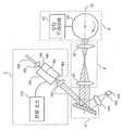
도 7은 본 발명에 따른 광파장 필터의 제7 예시적인 실시예에 대한 도면이다.7 is a diagram of a seventh exemplary embodiment of an optical wavelength filter according to the present invention.
도 8은 본 발명에 따른 동조 가능 레이저 소스를 사용한 스펙트럼 부호화 공초점 현미경(spectrally-encoded confocal microscope)의 예시적인 실시예에 대한 개략도이다.8 is a schematic diagram of an exemplary embodiment of a spectrally-encoded confocal microscope using a tunable laser source in accordance with the present invention.
도 9는 본 발명에 따른 동조 가능 레이저 소스를 사용한 주파수 영역(frequency-domain) 광 결맞음 단층촬영기 배열의 예시적인 실시예에 대한 개략도이다.9 is a schematic diagram of an exemplary embodiment of a frequency-domain optical coherence tomography array using a tunable laser source in accordance with the present invention.
도 10A는 본 발명에 따른 파장 필터의 제8 예시적인 실시예의 평면도이다.10A is a plan view of an eighth exemplary embodiment of a wavelength filter according to the present invention.
도 10B는 도 10A에 도시된 파장 필터의 상부 투시도이다.10B is a top perspective view of the wavelength filter shown in FIG. 10A.
도 1A는 본 발명에 따른 광파장 필터(1)의 제1 예시적인 실시예에 대한 블록도이다. 제1 예시적인 실시예에서, 광파장 필터(1)는 다양한 다른 응용에 사용될 수 있으며, 그 일반적인 예들이 후술된다. 이러한 예에서 필터(1)는 광원(2)을 통해서 하나 이상의 응용(3)에 연결될 수 있다. 예시적인 특정 응용에서, 필터(1)는 (예를 들어, 수동 광요소 또는 능동 광요소와 같은) 광원이 아닌 소자를 통해 (예를 들어, 응용(3) 중 하나 이상인) 응용과 함께 사용될 수 있거나 그 응용에 연결되어 사용될 수 있다는 것이 이해되어야 한다. 도 1A에 도시된 제1 예시적인 실시예에서, 광역스펙트럼 광원 및/또는 제어기(2, 이하, 광 제어기)는 파장 분산 요소(4)에 연결될 수 있다. 광 제어기(2)는 광 영상 처리 및 광 영상 시스템, 레이저 기계 가공 처리 및 시스템, 광리소그래피 및 광리소그래피 시스템, 레이저 토포그래피(topography) 시스템, 통신 처리 및 시스템 등을 포함하지만 이에 한정되지 않 는 것을 구비한 또는 그것을 위한 하나 이상의 과제를 수행하도록 구성된 응용(3)중 하나 이상에 더 연결될 수 있다. 파장 분산 요소(4)는 렌즈 시스템(6)에 연결될 수 있으며, 렌즈 시스템(6)은 빔 편향 소자(8)에 더 연결될 수 있다.1A is a block diagram of a first exemplary embodiment of an
광 제어기(2)는 광역 주파수(f) 스펙트럼을 갖는 광선 빔을 투과시키도록 구성된 다양한 시스템 및/또는 배열 중 하나 이상일 수 있다. 하나의 예시적인 실시예에서, 광선 빔은 시준(collimated) 광선 빔일 수 있다. 이 광선 빔은 가시광 스펙트럼 내의 (예를 들어, 적색, 청색, 녹색인) 복수의 파장 λ1 ... λn을 포함할 수 있다. 마찬가지로, 광 제어기(2)에 의해 제공된 광선 빔은 가시광 스펙트럼의 바깥쪽으로 정의될 수 있는 (예를 들어, 자외선, 근적외선 또는 원적외선인) 복수의 파장 λ1 ... λn을 포함할 수도 있다. 본 발명의 하나의 예시적인 실시예에서 광 제어기(2)는, 파장 동조 레이저 소스의 예시적인 실시예를 도시하는 도 3과 관련된 이하의 추가적인 상세한 설명에서 기술되는 단일 방향 광 투과 링(unilateral optical transmission ring)을 포함할 수 있다. 또한, 본 발명의 또 다른 예시적인 실시예에서 광 제어기(2)는 도 6과 관련된 이하의 추가적인 상세한 설명에서 기술되는 선형 공명 시스템을 포함할 수 있다.The
광파장 필터(1)의 파장 분산 요소(4)는 광 제어기(2)로부터 광선 빔을 수신하여 광선 빔을 다수의 방향을 갖는 복수의 파장으로 된 광선으로 통상적으로 분리시키도록 상세하게 구성된 하나 이상의 요소를 포함할 수 있다. 파장 분산 요소(4)는 또한 광학축(38)에 대하여 동일한 각 방향 또는 변위 내의 다른 파장을 갖는 광선의 일부를 안내하는데 효과적이다. 본 발명의 하나의 예시적인 실시예에서, 파장 분산 요소(4)는 광 분산 요소를 포함할 수 있으며, 광 분산 요소는 반사 격자, 투과 격자, 프리즘, 회절 격자, 음향 광학 회절 셀 또는 이들 요소들의 하나 이상의 조합을 포함할 수 있지만 이에 제한되지 않는다.The
광파장 필터(1)의 렌즈 시스템(6)은 파장 분산 요소로부터 광선의 분리된 파장을 수신하도록 구성된 하나 이상의 광 요소를 포함할 수 있다. 각각의 파장에서 광선은 광학축(38)에 대하여 일정 각에 있는 경로를 따라 전파된다. 각은 파장 분산 요소(4)에 의해 결정된다. 또한, 렌즈 시스템(6)은 광선의 파장들을 빔 편향 소자(8) 상에 위치된 소정 위치로 안내하거나 또는 조향하거나 그리고/또는 포커싱되도록 구성된다.The
빔 편향 소자(8)는 광선의 하나 이상의 불연속인 파장을 수신하여 이를 광학축(38)을 따라 렌즈 시스템(6)을 통해 파장 분산 요소(4)로 그리고 다시 광 제어기(2)로 선택적으로 다시 안내하도록 제어될 수 있다. 그런 다음, 광 제어기(2)는 광선의 수신된 불연속 상태의 파장을 하나 이상의 임의의 응용으로 선택적으로 안내할 수 있다. 빔 편향 소자(8)는 많은 다른 방향으로 제공될 수 있다. 예를 들어, 빔 편향 소자(8)는 다각 미러, 회전축 상에 배치된 평면 미러, 검류계 상에 배치된 미러 또는 음향 광변조기를 포함하지만 이에 한정되지 않는 요소로부터 제공될 수 있다.The
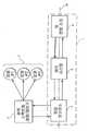
도 1B는 광파장 필터(1')의 제2 예시적인 실시예에 대한 개략도를 도시한다. 예시적인 광파장 필터(1')는 실질적으로 동일한 입력 및 출력 포트를 구비할 수 있 는 반사형 필터로서 구성될 수 있다. 입력/출력 광섬유(10)와 시준 렌즈(12)는 (도 1A를 참조하여 전술한 광 제어기(2)와 실질적으로 유사할 수 있는) 광 제어기(2')로부터 광파장 필터(1')로 입력을 제공할 수 있다. 광파장 필터(1')는 회절 격자(16), 광학 망원경 요소(6', 이하, 망원경(6')으로 지칭되며, 도 1A의 렌즈 시스템(6)과 아마 유사할 수 있음) 및 다각 미러 스캐너(24)를 포함한다. 망원경(6')은 두 개의 렌즈를, 예를 들어 4-f 구조를 갖는 제1 및 제2 렌즈(20, 22)를 포함할 수 있다.1B shows a schematic diagram of a second exemplary embodiment of a
도 1B에 도시된 광파장 필터(1')의 제2 예시적인 실시예에서, 망원경(6')은 실질적으로 광학축(38)을 따라 각각 중심 설정된 제1 및 제2 렌즈(20, 22)를 포함한다. 제1 렌즈(20)는 제1 렌즈(20)의 초점 거리(F1)와 대략 같을 수 있는 (예를 들어 회절 격자(16)인) 파장 분산 요소(4')로부터의 제1 거리에 위치될 수 있다. 제2 렌즈(22)는 제1 렌즈(20)의 초점 거리(F1)와 제2 렌즈(22)의 초점 거리(F2)의 합과 대략 같을 수 있는 제1 렌즈로부터의 제2 거리에 위치될 수 있다. 이러한 배열을 사용하여, 제1 렌즈(20)는 파장 분산 요소(4')로부터 광선의 하나 이상의 시준된 이산 파장을 수신할 수 있고, 광선의 시준된 하나 이상의 이산 파장의 각각의 파장에 대한 푸리에 변환(Fourier Transform)을 효과적으로 수행하여 영상면(image plane: IP) 상으로 투영되는 대략 동일한 하나 이상의 수렴 빔을 제공할 수 있다.In a second exemplary embodiment of the
영상면(IP)은 바람직하게는 제1 렌즈(20)와 제2 렌즈(22) 사이에 제1 렌즈(20)로부터 소정 거리에 위치된다. 본 발명의 하나의 예시적인 변형에 따라, 이러한 소정 거리는 제1 렌즈(20)의 초점 거리(F1)에 의해 한정될 수 있다. 이러한 하 나 이상의 수렴 빔이 영상면(IP)을 통해 전파된 후에, 이들 하나 이상의 수렴 빔은 제2 렌즈(22)에 의해 수신된 동일하거나 상응하는 하나 이상의 발산 빔을 형성한다. 제2 렌즈(22)는 발산 빔을 수신하여 광학축(38)에 대하여 소정 각도 변위를 갖는 대략 동일한 수의 시준 빔을 제공하도록 구성된다. 그러므로, 제2 렌즈(22)는 빔 편향 소자(8')의 소정 부분들로 시준 빔을 안내하거나 조향할 수 있다.The image plane IP is preferably located at a distance from the
본 발명의 제2 예시적인 실시예에 따른 망원경(6')은, 전술한 바와 같은 하나 이상의 특질을 제공할 뿐만 아니라 격자로부터의 발산 각분산(diverging angular dispersion)을 제2 렌즈(22) 이후의 수렴 각분산으로 전환하도록 구성된다. 이러한 결과는 필터의 고유 작동에 유리할 수 있다. 또한, 망원경(6')은 동조 범위와 선폭(linewidth)을 제어하고 다각 미러에서 빔 크기를 줄여 빔 클리핑(beam clipping)을 방지하는 조정 가능한 변수를 제공할 수 있다. 도 1B의 예시적인 실시예에 도시된 바와 같이, (예를 들어, 다각 미러 또는 배열(24)를 포함할 수 있는) 빔 편향 소자(6')는, 바람직하게는 광학축(38)에 대한 다각 배열(24)의 전방 미러면의 각도의 함수로서 오직 좁은 통과 대역(passband) 내에 있는 스펙트럼 성분만을 다시 반사시키도록 구성된다. 반사된 좁은 대역 광선은 회절되며 광섬유(10)에 의해 수신된다. 광학축에 대한 입사 빔(30)의 배향과 다각 배열(24)의 회전 방향(40)을 사용하여, 예를 들어 파장 증가(양성) 스캔 또는 파장 감소(음성) 스캔과 같은 파장 동조의 방향을 결정한다. 도 1B에 도시된 예시적인 배열은 양성 파장 스위프(sweep)를 생성할 수 있다. 다각 배열(24)이 12개의 면을 갖고 있는 것으로 도 1B에 도시되어 있지만, 12개의 면보다 작거나 많은 면을 갖는 다각 배열 도 사용될 수 있다는 것이 이해되어야 한다. 실질적인 기계적 한계를 일반적으로 고려하지 않았지만, 통상적인 제조 기법에 기초하여, 임의의 응용에서 사용되는 다각 배열(24)의 특정된 개수의 면(facet)들은 특정 응용에 대한 소정 스캐닝률(scanning rate)과 스캐닝 범위에 따라 달라질 수 있다.The
또한, 다각 배열(24)의 크기는 특정 응용의 선택(preference)에 기초하여 선택될 수 있으며, 바람직하게는 다각 배열(24)의 제조 가능성 및 중량을 포함하지만 이에 제한되지 않는 특정 요인을 고려하여 선택될 수 있다. 다른 초점 거리를 갖는 렌즈(20, 22)가 제공될 수 있다는 것도 이해되어야 한다. 예를 들어, 렌즈(20, 22)는 다각 배열(24)의 대략 중심점(24a)에 초점을 제공하도록 선택되어야 한다.In addition, the size of the
하나의 예시적인 실시예에서, 섬유 시준기(12)로부터 격자로 입사된 광역 광학 스펙트럼을 갖는 가우시안 빔(30, Gaussian beam)이 사용될 수 있다. 공지된 격자 방정식은 λ=p·(sinα+sinβ)로 표현되는데, λ는 광파장이고, p는 격자 피치이며, α와 β는 각각 격자의 수직축(42)에 대한 빔의 입사각과 회절각이다. 필터의 동조 범위의 중심 파장은 λ0=p·(sinα+sinβ0)로 정의될 수 있는데, β0는 망원경의 광학축(38)과 격자 수직축 사이의 각이다. 필터의 FWHM 대역폭은 (δλ)FWHM/λ0=A·(p/m)cosα/W로 정의되는데, A는 이중 통과(double pass)에 대해
필터의 동조 범위는 제1 렌즈(20)의 유한한 개구수(numerical aperture)에 의해 제한될 수 있다. 빔 클리핑이 없는 제1 렌즈(20)의 수용각(acceptance angle)은 Δβ=(D1-Wcosβ0/cosα)/F1로 정의될 수 있는데, D1과 F1은 각각 제1 렌즈(20)의 직경과 초점거리이다. 이러한 식은 Δλ=p cosβ0·Δβ를 통해 필터 동조 범위와 관련된다. 다각 미러의 다중 면 성질로부터 유래되는, 필터의 예시적인 설계 변수 중 하나는 후술되는 자유 스펙트럼 범위이다. 스펙트럼 성분은 제1 렌즈(20)와 제2 렌즈(22)를 통해 전파된 후에 예를 들어 β'=-(β-β0)·(F1/F2)인 광학축(38)에 대한 각(β')에서 빔 전파 축을 가질 수 있는데, F1와 F2는 각각 제1 렌즈(20)와 제2 렌즈(22)의 초점 거리이다. 다각 배열(24)은
수학식1에 기재된 바람직한 두 가지 조건식이 만족되면, 필터에 의한 레이저 동조의 듀티 사이클(duty cycle)은, 예를 들어 빔 클리핑에 의해 기인한 초과 손실 없이 100%일 수 있다.If the two preferred conditional expressions described in

첫째 식은 제2 렌즈(22) 이후의 빔 폭이 면 폭보다 작아야 한다는 조건으로부터 유도될 수 있다. 둘째 식은 다각 배열(24)에서 서로 중첩되지 않아야 하는 동조 범위의 최저 파장(32)과 동조 범위의 최고 파장(34)에의 각각의 두 빔으로부터 유도될 수 있다. 수학식1에서 S는 다각 배열(24)의 전면 미러과 제2 미러(22) 사이의 거리를 나타낸다.The first equation can be derived from the condition that the beam width after the
W=2.4mm, p=1/1200mm, α=1.2라디안, β0=0.71라디안, m=1, D1=D2=25mm, F1=100mm, F2=45mm, N=24, R=25mm, L=6.54, S=5mm, θ=0.26라디안, λ0=1320nm인 매개 변수를 갖는 광학 성분을 선택할 수 있다. 매개 변수로부터, 필터의 이론적인 FWHM 대역폭, 동조 범위 및 자유 스펙트럼 범위는 각각 (δλ)FWHM=0.09nm, Δλ=126nm 및 (Δλ)FSR=74nm로 계산될 수 있다. 수학식1에서 두 가지 조건식은 특정 허용범위를 만족시킬 수 있다.W = 2.4mm, p = 1 / 1200mm, α = 1.2 radians, β0 = 0.71 radians, m = 1, D1 = D2 = 25mm, F1 = 100mm, F2 = 45mm, N = 24, R = Optical components having parameters of 25 mm, L = 6.54, S = 5 mm, θ = 0.26 radians and λ0 = 1320 nm can be selected. From the parameters, the theoretical FWHM bandwidth, tuning range and free spectral range of the filter can be calculated as (δλ)FWHM = 0.09nm, Δλ = 126nm and (Δλ)FSR = 74nm, respectively. In
도 1C는 본 발명에 따라 동일한 다각형 회전 속도에서 동조 속도를 2배로 하는 파장 동조 가능 필터 배열의 제3 예시적인 실시예에 대한 도면을 도시한다. 이 러한 예시적인 실시예에서, 다각 배열(24)의 미러 표면은 렌즈(22)로부터 실질적으로 거리(F2)에 위치설정되고, 광선 빔은 (다각 배열(24)의 미러면으로부터 망원경으로 직접 다시 반사되기보다는) 0이 아닌 각도로 반사된다. 다각 배열(24)로부터의 반사광의 스위프각은 다각 배열(24)의 회전각의 2배이다. 다각 배열(24)에 대한 λ1과 λN 사이의 입사각 차이(90)가 예를 들어 각θ인 다각형의 면대면 각(92)과 대략 같을 때, 다각 배열(24)의 각θ인 회전에 대해 반사광의 스위프각(94)은 2θ이다. 다각 배열(24)로부터의 반사된 광선 빔을 바람직하게는 다각 배열(24)로 그리고 (예를 들어, 도1B의 망원경(6')과 유사한) 망원경으로 다시 안내하는 두 개의 반사경(100, 102)을 서로 각θ로 위치 설정함으로써, 하나의 면대면 각θ의 다각 회전에 대해 λ1으로부터 λN까지 2번의 파장 스캔이 달성된다.1C shows a diagram of a third exemplary embodiment of a wavelength tunable filter arrangement that doubles the tuning speed at the same polygonal rotation speed in accordance with the present invention. In this exemplary embodiment, the mirror surface of the
본 발명의 제4 예시적인 실시예를 도시하는 도 1D에서, 다각 배열(24)에 대한 λ1과 λN 사이의 입사각 차이(90)는 예를 들어 φ(=θ/K, K>1인 경우)인 다각 면대면 각(92)보다 작다. 이것은 격자 피치를 감소시키고 F2/F1비를 증가시킴으로써 달성될 수 있다. 이러한 예시적인 실시예에서, 필터 동조 속도는 다각 배열(24)의 회전 속도 또는 다각 배열(24)의 면의 개수를 증가시키지 않으면서 계수 2K 만큼 증가될 수 있다.In FIG. 1D showing a fourth exemplary embodiment of the present invention, the
필터 동조 속도는 광선 빔이 다각 배열(24)에 의해 여러 차례 반사됨으로써 더 증가될 수 있다. 도 1E에 도시된 본 발명의 제5 예시적인 실시예는 계수 4K 만큼 동조 속도를 증가시키는 배열인데, K는 각(90)에 대한 각(92)의 비율(K=θ/φ) 이다. 광선 빔은 다각 배열(24)에 의해 2 차례 (예를 들어 4 차례 왕복 트립) 반사되므로, 반사광의 스위프각(94)은 각 4θ가 되며, 동조 속도는 4K배 더 빨라진다. 이러한 반사는 또한 표면(100, 102, 104, 106 및 108)의 반사에 의해 도움될 수도 있다. 필터 배열의 이러한 예시적인 실시예가 사용되어 필터의 자유 스펙트럼 범위(filter spectral range: FSR)를 넓힐 수 있다. 예를 들어, 도 1E에 도시된 실시예에서 최종 반사경(102) 중 하나가 제거되면, 필터의 FSR은 2배 더 넓어진다. 이경우 동조 속도 증가는 없을 수 있다. 마찬가지로, 도 1E에서 오직 하나의 최종 반사경(100)만을 보유할 수 있다. 이 실시예에서 FSR은 4배 더 넓어질 수 있다.The filter tuning speed can be further increased by the ray beam being reflected several times by the
도 1F는 두 개의 광 입력과 두 개의 광 출력을 수용하는 다각 동조 필터를 제공하는 본 발명의 제6 예시적인 실시예를 도시한다. 예를 들어, 이 필터의 2 이상의 입력 및 출력을 유지하기 위해, 입력/출력 섬유(10, 10'), 시준 렌즈(12, 12'), 회절 격자(16, 16') 및 망원경을 각각 포함하고 있는 2 이상의 광학 배열 세트가 동일한 다각 배열(24)을 공유할 수 있다. 다각 배열(24)의 스캐닝 미러가 구조적으로 회전축에 대한 등방성이므로, 다각 배열(24)에 광선 빔을 전달할 수 있는 특정 광학 배열은 임의의 방향으로부터 수용될 수 있다. 도 1F의 실시예에서 2개의 광학적 배열 세트가 동일한 다각 스캐너를 사용하므로, 각각의 스캐닝 광투과 스펙트럼이 동기화된다. 도 1F의 예시적인 실시예는 고유한 입력 및 출력 광채널을 각각 갖는 (2보다 큰) 복수의 광학 배열을 포함하도록 확장될 수 있음이 이해되어야 한다.1F shows a sixth exemplary embodiment of the present invention providing a polygonal tuning filter that accepts two light inputs and two light outputs. For example, to maintain two or more inputs and outputs of this filter, input /
본 발명의 제6 실시예에 따른 전술한 다각 동조 필터의 하나의 예시적인 응용은 광대역 파장 스캐닝 광원일 수 있다. 본 발명의 제7 예시적인 실시예를 도시하는 도 1G에서, 제1 광대역 광원(60)은 파장 λ1 내지 λi을 가질 수 있는 광신호를 제공하며, 제2 광대역 광원(600)은 파장 λi-j 내지 λN을 가질 수 있는 또 다른 광신호를 제공한다. 파장 λ1 내지 λi 및 파장 λi-j 내지 λN을 각각 지지하는 두 개의 광학 배열이 동시에 대략 동일한 파장을 출력하도록 동기화될 때, 이러한 예시적인 배열은 λ1으로부터 λN까지 선형 스캔률을 갖는 광대역 파장 스캐닝 광원이 될 수 있다. 다각 스캐닝 필터의 FSR은 임의의 광학적 성능 열화 없이 200nm 이상으로 넓게 조정 가능하므로, 상이한 중심 파장을 갖는 2 이상의 광대역 광원이 이 필터와 결합되어 200nm 동조 대역폭에 걸쳐 선형 스캐닝 광원을 제공할 수 있다. 도 1G의 실시예는 (예를 들어 2보다 큰) 복수의 광학 배열과 (예를 들어 2보다 큰0 복수의 광대역 광원을 포함하도록 확장될 수 있다.One exemplary application of the aforementioned polygonal tuning filter according to the sixth embodiment of the present invention may be a broadband wavelength scanning light source. In FIG. 1G showing a seventh exemplary embodiment of the present invention, the first
도 1G에 도시된 예시적인 실시예는 또한 각각의 광학 배열의 파장 동조 대역과 광대역 광원이 불연속 되도록 구성될 수도 있다. 이러한 구성에서, 동조 대역은 연속이거나 또는 불연속인 순차 방식으로 또는 동시에 스위프될 수 있다.The example embodiment shown in FIG. 1G may also be configured such that the wavelength tuning band of each optical array and the broadband light source are discontinuous. In such a configuration, the tuning bands can be swept in a sequential manner or simultaneously in a continuous or discontinuous manner.
도 2는 본 발명의 예시적인 실시예에 따른 필터의 측정 특성에 대한 예시적인 그래프를 도시한다. 예를 들어 곡선(48)인 필터의 정규화 반사 스펙트럼은 반도체 광증폭기(semiconductor optical amplifier: SOA)와 광스펙트럼 분석기로부터의 광대역 증폭기 자발적 방출을 사용하여 측정될 수 있다. 다각 배열(24)이 15.7kHz의 최대 속도로 회전하는 동안, 광스펙트럼 분석기는 피크홀드(peak-hold) 모드에서의 정규화 처리(throughput) (반사) 스펙트럼을 얻거나 기록할 수 있다. 측정된 동조 범위는 126nm인 이론값보다 실질적으로 작은 90nm일 수 있다. 격자로부터의 빔의 비교적 큰 각발산(angular divergence)과 관련된, 망원경(6')의 주로 마당굽음수차(field curvature aberration)인 수차에 기인할 수 있는 편차를 가질 수 있다. 이러한 수차는 종래 공지된 최적 렌즈 설계를 사용하여 수정될 수 있다. 도 2에 도시된 곡선(46)은 다각 배열이 특정 위치에서 정적일 때의 처리 스펙트럼을 도시한다. 관측된 자유 스펙트럼 범위는 73.5nm로 이론적 계산과 일치한다. 곡선(46)의 FWHM 대역폭의 측정값은 0.12nm이다. 측정된 FWHM과 0.09nm인 이론적 한계 사이의 편차는 광학 요소의 결함과 수차를 고려하면 타당하다.2 shows an exemplary graph of the measurement characteristics of a filter according to an exemplary embodiment of the present invention. For example, the normalized reflection spectrum of the filter,
도 3은 본 발명에 따른 파장 동조 레이저 소스의 예시적인 실시예를 도시한다. 예를 들어, 다각형 기반 필터(polygon-based filter)는 패러데이 순환기(50, Faraday circulator)를 통해 확장 공동(extended-cavity) 반도체 레이저로 통합될 수 있다. 공동내(intra-cavity) 요소는 단일 모드 광섬유(10)에 의해 접속될 수 있다. 이득 매체는 (예를 들어, SOA, 필립스, CQF 882/e인) 반도체 광증폭기(52)일 수 있다. 레이저 출력(72)은 광섬유 융착 커플러(70, fiber-optic fused coupler)의 90% 포트를 통해 얻을 수 있다. 2개의 편광 제어기(64, 62)를 사용하여, 공동내 광선(intra-cavity light)의 편광 상태들을 격자(16)의 최대 효율축과 SOA(50)의 최대 이득축에 정렬할 수 있다. 전류 소스(54)는 SOA(50)에 주입 전류를 제공할 수 있다. 다각 배열(24)은 모터 드라이버(97)에 의해 구동되고 제어될 수 있다. 잠재적 응용에 유용한 동기 신호를 생성하기 위해, 대략 5%의 레이저 출력이 0.12 nm의 대역폭을 갖는 가변 파장 필터(80)를 통해 광검출기(82)로 안내될 수 있다. 이러한 예시적인 실시예에서, 필터의 중심 파장은 1290nm에 고정되었다. 검출기 신호는 레이저의 출력 파장이 고정 파장 필터의 좁은 통과 대역을 통해 스위프되는 경우에 단펄스(short pulse)를 생성할 수 있다. 동기 펄스의 타이밍은 필터의 중심 파장을 변화시킴으로써 제어될 수 있다.3 shows an exemplary embodiment of a wavelength tuned laser source according to the present invention. For example, a polygon-based filter may be integrated into an extended-cavity semiconductor laser through a
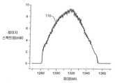
도 4A는 본 발명에 따른 레이저 소스의 예시적인 제1 출력 특성(레이저 스펙트럼 대 파장)의 그래프를 도시하며, 도 4B는 본 발명에 따른 레이저 소스의 예시적인 제2 출력 특성(출력 대 시간)의 그래프를 도시한다. 도 4를 다시 참조하면, 곡선(110)은 피크홀드 모드에서, 예를 들어 다각 배열이 15.7kHz로 회전하는 경우에 광학 스펙트럼 분석기에 의해 측정된 레이저의 출력 스펙트럼을 나타낸다. 에지 대 에지의 스위프 범위는 필터의 자유 스펙트럼 범위와 동일하게 1282nm 내지 1355nm로 관측되었다. 측정된 스펙트럼이 정방형 프로파일이 아니라 가우시안형(Gaussian-like) 프로파일인 것은, 공동 내에서의 복굴절과 필터의 편광 민감도에 의해 발생되는 편광에 따른(polarization-dependent) 공동 손실에 주로 기인할 수 있다. 최대 스위프 범위와 출력을 얻도록 편광 제어기를 조정하는 것이 바람직할 수 있다. 도 4B에서, 곡선(114)은 시간 영역에서의 예시적인 레이저 출력이다. 상부 표시선(112)은 고정 파장 필터를 통해 얻을 수 있는 동기 신호이다. 면으로부터 면까지의 출력 변화의 진폭은 3.5% 미만이었다. 피크와 평균 출력은 각각 9mW와 6mW였다. 광학 스펙트럼 분석기가 시평균된(time-averaged) 스펙트럼을 스 펙트럼 분석기의 스위프 속도보다 훨씬 빠른 레이저 동조 속도로 기록하므로, 도 4A의 곡선(110)의 y축 축척은 시간 영역 측정으로부터 조정(calibration)될 수 있다.4A shows a graph of an exemplary first output characteristic (laser spectrum vs. wavelength) of a laser source according to the invention, and FIG. 4B shows an exemplary second output characteristic (output vs. time) of a laser source according to the invention. Show the graph. Referring back to FIG. 4, the
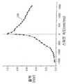
대역내 4 파 혼합 현상(intraband four-wave mixing phenomenon)의 결과로서, 광선이 SOA 이득 매체를 통과할 때, 공동내 레이저광의 광스펙트럼 내에 주파수 다운시프트(downshift)가 발생할 수 있다. 주파수 다운시프트의 존재하는 경우, 양성 파장 스위프 방향으로 파장 스캐닝 필터를 작동시킴으로써 더 큰 출력이 생성될 수 있다. 도 5는 동조 속도의 함수로서 측정된 레이저 출력의 정규화 피크 출력의 예시적인 도면이다. 본 발명에 따른 배열의 예시적인 실시예의 광학축(38)에 대한 격자의 배향과 시준기의 위치를 플리핑(flipping)함으로써, 음성(negative) 동조 속도를 얻을 수 있다. 필터의 물리적인 매개 변수를 두 개의 동조 방향에 동일하게 하는 것이 바람직할 수 있다. 자기 주파수 편이(self-frequency shift)와 양성 동조의 조합 작용에 의해, 보다 높은 출력을 얻을 수 있고, 곡선(120)에 표시된 바와 같이 더 높은 동조 속도로 레이저가 동작될 수 있다. 그러므로, 양성 파장 스캔이 바람직한 작동일 수 있다. 출력은 동조 속도의 증가에 따라 감소될 수 있다. 동조 속도에 대한 출력의 민감도를 줄이기 위해 짧은 공동 길이가 바람직할 수 있다. 이 경우에 자유 공간 레이저 공동이 바람직할 수 있다.As a result of the in-band four-wave mixing phenomenon, as the light passes through the SOA gain medium, frequency downshifts may occur in the light spectrum of the laser light in the cavity. In the presence of frequency downshift, larger output can be produced by operating the wavelength scanning filter in the positive wavelength sweep direction. 5 is an exemplary diagram of normalized peak output of laser power measured as a function of tuning speed. By flipping the orientation of the grating and the position of the collimator with respect to the
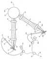
본 발명에 따른 자유 공간 확장 공동 반도체 동조 가능 레이저 배열의 예시적인 실시예가 도 6에 도시되어 있다. 기판 칩(160) 상에 제조된 반도체 도파관 (162)은 시준 렌즈(180)를 통해 다각 스캐닝 필터에 연결될 수 있다. 그 전면(164)은 반사 방지 코팅될 수 있으며, 출력면(166)은 최적 반사율을 갖도록 클리브(cleave)되거나 바람직하게는 유전체로 코팅될 수 있다. 레이저 출력(190)은 출력 커플링 렌즈(182)를 통해 얻어질 수 있다. 동기 출력은, 다각 스캐너(24)로부터 재반사된 광선에 대한 0 차수 회절 경로 상에 위치설정된 렌즈(140), 핀홀(142) 및 광검출기(144)를 사용하여 얻어질 수 있다. 광검출기(144)는 특정 파장의 광학 빔의 초점이 핀홀(142)을 통해 스위프되는 경우에 단펄스를 생성할 수 있다. 다른 형태의 이득 매체는 희토류 이온 도핑 섬유, Ti:Al2O3 및 Cr3+:포스터라이트(forsterite)를 포함하지만 이에 한정되지는 않는다. 제1 및 제2 렌즈(20, 22)는 바람직하게는 특히 낮은 마당굽음(field curvature) 수차 및 낮은 코마(coma)를 갖는 색지움렌즈(achromat)일 수 있다.An exemplary embodiment of a free space expanding cavity semiconductor tunable laser arrangement according to the present invention is shown in FIG. 6. The
도 7은 도 7에 도시된 바와 같이 입력 시준 렌즈(12), 회절 격자(6), 초점 렌즈(200), 회전 디스크(210)을 포함하는 파장 동조 가능 필터의 또 다른 예시적인 실시예를 도시한다. 회절 격자(16)는 바람직하게는 초점 길이를 갖는 오목 곡률을 가지며 따라서 초점 렌즈(200) 사용에 대한 필요성을 제거할 수 있다. 회절 격자는 프리즘과 같은 다른 각분산 요소로 대체될 수 있다. 회전 디스크(210)의 표면 상에 바람직하게는 하나 이상의 반사경(212)이 증착될 수 있다. 바람직하게는, 반사경(212)은 주기적으로 그리고 방사상으로 패터닝된 복수의 좁은 줄무늬(stripe)를 포함할 수 있다. 반사경의 재료는 바람직하게는 금이다. 디스크(210)는 경량 플라스틱 또는 실리콘 기판으로 만들 수 있다. 디스크의 상면 상에 증착된 반사경 대신에, 디스크는 디스크의 배면에 부착되거나 디스크로부터 독립적으로 지지되는 단일 반사경에 의해 후속되는 일련의 관통 구멍을 구비할 수 있다. 광섬유(10)로부터 입사된 상이한 파장들의 광학 빔이 격자(16)에 의해 회절되고 렌즈(200)에 의해 포커싱(focusing)된 후에 디스크의 표면상에 선(line)으로 조사된다. 회전 디스크의 반사경에 도달한 빔은 재반사되어 광섬유(10)에 의해 수신될 수 있다. 예를 들어, 미러(202)를 사용하여 디스크 상으로 빔의 접근을 용이하게 할 수 있다.FIG. 7 illustrates another exemplary embodiment of a wavelength tunable filter comprising an
렌즈(200)로부터 디스크(210)의 반사경까지의 거리는 렌즈(200)의 초점거리(F)와 대략 같을 수 있다. 필터의 동조 범위는 Δλ=p cosβ0(D/F)로 주어지는데, D는 줄무늬 사이의 거리를 나타낸다. 줄무늬의 폭(w)은 바람직하게는 디스크의 표면에서 빔 스폿 크기(beam spot size)(ws)인

본 발명의 예시적인 실시예 중 두 개의 예시적인 응용이 후술될 것이다. 도 8은 전술한 동조 가능 레이저 소스(300)를 사용하는 스펙트럼 부호화 공초점 현미경(spectrally encoded confocal microscope: SECM)의 예시적인 실시예에 대한 블록도를 도시한다. SECM의 기본 원리는, 상세한 설명이 전체로서 본 명세서에 참조로서 합체되는 미국특허 제6,341,036호에 상세히 설명되어 있다. 예시적인 탐침(310)은 두 실리콘 프리즘(314, 316) 사이에 제공된 투과 격자(312), 시준기(318) 및 현미경 대물 렌즈(320)를 포함한다. 탐침은 샘플(330)의 다른 위치 상으로 빔을 스캐닝하는 마이크로 작동기(322, micro actuator)를 구비한다. 작동기(322)는 레이저 소스의 동조 속도보다 실질적으로 느린 속도로 작동기 드라이버(324)에 의해 구동될 수 있다. 탐침 움직임은 바람직하게는 회전식 또는 병진식이며, 레이저 소스의 동기 출력에 동기화된다. 일례에서, 파장 스위프 주파수는 15.7kHz일 수 있으며, 탐침 스캔 주파수는 1초에 30프레임의 영상을 얻을 수 있는 30Hz일 수 있다. 대물 렌즈(320)는 마이크로미터 차수의 횡 해상도(transverse resolution)과 몇 개의 마이크로미터의 공초점 변수를 제공하도록 높은 개구수(nigh numerical aperature)를 갖는다. 광학 빔의 초점은 탐침의 스캐닝 움직임과 광원의 스위프 출력 파장에 의해 샘플(330) 상에서 제시간에 연속하여 스캐닝될 수 있다. 샘플로부터 복귀되는 광출력은, 빔이 소정 시간에 좁은 웨이스트(waist)로 포커싱 다운(focusing down)되는 작은 단면(section) 내에서의 샘플의 반사율에 비례한다. 샘플의 2차원 정면(en-face) 영상은 신호처리기(344)에 의해 구성된다. 검출기(340)는 바람직하게는 트랜스임피던스(transimpedance) 증폭기(342)에 의해 후속되는 애벌란시 광다이오드(avalanche photodiode: APD)이다. 반사 출력은 패러데이 순환기 (350) 또는 광섬유 커플러를 통해 수신될 수 있다.Two exemplary applications of the exemplary embodiments of the present invention will be described below. 8 shows a block diagram of an exemplary embodiment of a spectrally encoded confocal microscope (SECM) using the
본 발명의 예시적인 실시예의 또 다른 예시적인 응용은, 상세한 설명이 전체로서 참조로서 본 명세서에 합체되는 미국특허 제5,956,355호에 상세하게 설명된 광학 결맞음 단층촬영기(optical coherence tomography: OCT)에 대한 것이다. 도 9에 도시된 하나의 예시적인 구성에서, 동조 가능 소스(300)의 출력은 광섬유 커플러(410)를 통해 샘플(330)로 안내될 수 있다. 탐침에서 대물렌즈(412)는 통상적으로 표면 근처에 또는 샘플(330) 내에 초점을 제공할 수 있다. 마이켈슨 간섭계의 두 아암 사이의 광학 경로 길이가 실질적으로 부합되는 위치에서 기준 아암(120) 내에 기준 미러(420)가 위치될 수 있다. 이와는 달리, 기준 경로는 투과성 비반사 구성으로 구성될 수 있다. 검출기(430)는 핀(PIN) 광다이오드일 수 있으며, 유한 주파수 대역폭을 갖는 트랜스임피던스 증폭기(432)가 그 다음에 위치된다. 검출기는 바람직하게는 다양한 편광 및 이중 밸런스 검출(polarization diverse and dual-balanced detection)을 통합할 수 있다. 검출기 신호는 샘플의 깊이 영상(depth image)을 구성할 수 있도록 고속 푸리에 변환을 통해 처리기(434)에서 처리될 수 있다. 탐침은 샘플의 3차원 영상이 얻어질 수 있도록 작동기(414)와 작동기 드라이버(416)에 의해 스캐닝될 수 있다.Another exemplary application of an exemplary embodiment of the present invention is to an optical coherence tomography (OCT) described in detail in US Pat. No. 5,956,355, the disclosure of which is incorporated herein by reference in its entirety. . In one example configuration shown in FIG. 9, the output of
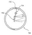
도 10A 및 도 10B는 본 발명에 따른 파장 동조 가능 필터의 또 다른 예시적인 실시예의 평면도 및 사시도이다. 이러한 예시적인 실시예의 각편향 광학 요소(700, angularly deflecting optical element)는, 다각형의 면들이 중공 실린더의 내경 상에 위치되는 회전 다각 배열(24)일 수 있다. 회절 격자와 같은 분산 요소 (702)는 다각 배열(24)의 중심에 위치 설정될 수 있다. 광속은 광섬유를 통해 격자에 전달되며 격자 상으로 시준될 수 있으므로, 광속의 각각의 주파수 성분은 상이한 각(Θ)으로 회절된다. 단지 하나의 좁은 주파수 범위만이 다각 배열(24)의 하나의 면에 실질적으로 직교할 수 있으며, 따라서 이러한 주파수 범위가 회절 격자로 재반사되고 광섬유(704/706)에 의해 수집될 수 있다. 실린더가 회전하는 동안, 조사된 다각 배열의 면들에 대한 면수직(surface normal) 방향을 새로운 좁은 주파수 범위와 정렬할 수 있다. 실린더를 회전시킴으로써, 그에 따라 주파수 동조가 달성될 수 있다. 실린더 회전각이 크게 될 때, 다각 배열(24)의 인접한 면이 격자로부터 회절된 광속과 정렬될 수 있으며, 필터는 또 다른 주파수 동조 주기를 반복할 것이다. 자유 스펙트럼 범위 및 공차는 다각형 직경, 면의 개수, 시준 빔 직경 및 회절 격자 홈 밀도(diffraction grating groove density)에 의해 제어될 수 있다.10A and 10B are plan and perspective views of another exemplary embodiment of a wavelength tunable filter according to the present invention. The angularly deflecting
전술한 설명은 단지 본 발명의 원리만을 설명한다. 전술한 실시예에 대한 다양한 변형과 수정은 본 명세서의 상세한 설명과 관련된 당업자에게 명백할 것이다. 예를 들어, 본 명세서에 기재된 본 발명은 미국특허출원번호 제60/514,769호에 개시된 예시적인 방법, 시스템 및 장치와 함께 사용 가능하다. 그러므로 당업자라면 본 명세서에 명시적으로 도시되거나 기술되지는 않았더라도 본 발명의 원리를 구체화하고 따라서 본 발명의 사상과 범위 내에 속하는 다양한 시스템, 배열 및 방법을 안출할 수 있을 것이라는 것을 이해할 것이다.The foregoing description merely illustrates the principles of the invention. Various modifications and variations to the embodiments described above will be apparent to those skilled in the art related to the detailed description herein. For example, the invention described herein can be used with the exemplary methods, systems, and apparatus disclosed in US Patent Application No. 60 / 514,769. Therefore, those skilled in the art will understand that although not explicitly shown or described herein, it will be possible to embody the principles of the present invention and thus devise various systems, arrangements and methods that fall within the spirit and scope of the invention.
Claims (56)
Translated fromKoreanApplications Claiming Priority (5)
| Application Number | Priority Date | Filing Date | Title |
|---|---|---|---|
| US47660003P | 2003-06-06 | 2003-06-06 | |
| US60/476,600 | 2003-06-06 | ||
| US51476903P | 2003-10-27 | 2003-10-27 | |
| US60/514,769 | 2003-10-27 | ||
| PCT/US2004/018045WO2005001401A2 (en) | 2003-06-06 | 2004-06-04 | Process and apparatus for a wavelength tuning source |
Related Child Applications (4)
| Application Number | Title | Priority Date | Filing Date |
|---|---|---|---|
| KR1020117017622ADivisionKR101204370B1 (en) | 2003-06-06 | 2004-06-04 | Process and apparatus for a wavelength tunning source |
| KR1020117017623ADivisionKR101130739B1 (en) | 2003-06-06 | 2004-06-04 | Papparatus for a wavelength tunning source |
| KR1020127023854ADivisionKR101546024B1 (en) | 2003-06-06 | 2004-06-04 | Process and apparatus for a wavelength tunning source |
| KR1020137032412ADivisionKR20130138867A (en) | 2003-06-06 | 2004-06-04 | Process and apparatus for a wavelength tunning source |
Publications (2)
| Publication Number | Publication Date |
|---|---|
| KR20060028684A KR20060028684A (en) | 2006-03-31 |
| KR101386971B1true KR101386971B1 (en) | 2014-04-18 |
Family
ID=33555425
Family Applications (5)
| Application Number | Title | Priority Date | Filing Date |
|---|---|---|---|
| KR1020057023416AExpired - LifetimeKR101386971B1 (en) | 2003-06-06 | 2004-06-04 | Process and apparatus for a wavelength tunning source |
| KR1020117017622AExpired - LifetimeKR101204370B1 (en) | 2003-06-06 | 2004-06-04 | Process and apparatus for a wavelength tunning source |
| KR1020137032412ACeasedKR20130138867A (en) | 2003-06-06 | 2004-06-04 | Process and apparatus for a wavelength tunning source |
| KR1020117017623AExpired - LifetimeKR101130739B1 (en) | 2003-06-06 | 2004-06-04 | Papparatus for a wavelength tunning source |
| KR1020127023854AExpired - LifetimeKR101546024B1 (en) | 2003-06-06 | 2004-06-04 | Process and apparatus for a wavelength tunning source |
Family Applications After (4)
| Application Number | Title | Priority Date | Filing Date |
|---|---|---|---|
| KR1020117017622AExpired - LifetimeKR101204370B1 (en) | 2003-06-06 | 2004-06-04 | Process and apparatus for a wavelength tunning source |
| KR1020137032412ACeasedKR20130138867A (en) | 2003-06-06 | 2004-06-04 | Process and apparatus for a wavelength tunning source |
| KR1020117017623AExpired - LifetimeKR101130739B1 (en) | 2003-06-06 | 2004-06-04 | Papparatus for a wavelength tunning source |
| KR1020127023854AExpired - LifetimeKR101546024B1 (en) | 2003-06-06 | 2004-06-04 | Process and apparatus for a wavelength tunning source |
Country Status (11)
| Country | Link |
|---|---|
| US (6) | US7519096B2 (en) |
| EP (14) | EP2011434A3 (en) |
| JP (4) | JP2007526620A (en) |
| KR (5) | KR101386971B1 (en) |
| AT (1) | ATE410666T1 (en) |
| AU (1) | AU2004252482B2 (en) |
| CA (1) | CA2527930C (en) |
| DE (1) | DE602004016998D1 (en) |
| ES (1) | ES2310744T3 (en) |
| TW (1) | TWI346428B (en) |
| WO (1) | WO2005001401A2 (en) |
Families Citing this family (226)
| Publication number | Priority date | Publication date | Assignee | Title |
|---|---|---|---|---|
| US7231243B2 (en) | 2000-10-30 | 2007-06-12 | The General Hospital Corporation | Optical methods for tissue analysis |
| US9295391B1 (en) | 2000-11-10 | 2016-03-29 | The General Hospital Corporation | Spectrally encoded miniature endoscopic imaging probe |
| AT503309B1 (en)* | 2001-05-01 | 2011-08-15 | Gen Hospital Corp | DEVICE FOR DETERMINING ATHEROSCLEROTIC BEARING BY MEASURING OPTICAL TISSUE PROPERTIES |
| US7557929B2 (en) | 2001-12-18 | 2009-07-07 | Massachusetts Institute Of Technology | Systems and methods for phase measurements |
| US7355716B2 (en) | 2002-01-24 | 2008-04-08 | The General Hospital Corporation | Apparatus and method for ranging and noise reduction of low coherence interferometry LCI and optical coherence tomography OCT signals by parallel detection of spectral bands |
| US8054468B2 (en)* | 2003-01-24 | 2011-11-08 | The General Hospital Corporation | Apparatus and method for ranging and noise reduction of low coherence interferometry LCI and optical coherence tomography OCT signals by parallel detection of spectral bands |
| CA2514189A1 (en)* | 2003-01-24 | 2004-08-12 | The General Hospital Corporation | System and method for identifying tissue using low-coherence interferometry |
| US7339727B1 (en)* | 2003-01-30 | 2008-03-04 | Northrop Grumman Corporation | Method and system for diffractive beam combining using DOE combiner with passive phase control |
| EP2436307B1 (en) | 2003-03-31 | 2015-10-21 | The General Hospital Corporation | Speckle reduction in optical coherence tomography by path length encoded angular compounding |
| KR101386971B1 (en) | 2003-06-06 | 2014-04-18 | 더 제너럴 하스피탈 코포레이션 | Process and apparatus for a wavelength tunning source |
| EP2280256B1 (en) | 2003-10-27 | 2016-11-16 | The General Hospital Corporation | Method and apparatus for performing optical imaging using frequency-domain interferometry |
| US7813644B2 (en)* | 2004-05-10 | 2010-10-12 | Raytheon Company | Optical device with a steerable light path |
| KR101239250B1 (en)* | 2004-05-29 | 2013-03-05 | 더 제너럴 하스피탈 코포레이션 | Process, system and software arrangement for a chromatic dispersion compensation using reflective layers in optical coherence tomography (oct) imaging |
| AU2005270037B2 (en)* | 2004-07-02 | 2012-02-09 | The General Hospital Corporation | Endoscopic imaging probe comprising dual clad fibre |
| EP1782020B1 (en) | 2004-08-06 | 2012-10-03 | The General Hospital Corporation | Process, system and software arrangement for determining at least one location in a sample using an optical coherence tomography |
| WO2006024014A2 (en) | 2004-08-24 | 2006-03-02 | The General Hospital Corporation | Process, system and software arrangement for measuring a mechanical strain and elastic properties of a sample |
| EP2272421A1 (en) | 2004-08-24 | 2011-01-12 | The General Hospital Corporation | Method and apparatus for imaging of vessel segments |
| JP4527479B2 (en)* | 2004-09-10 | 2010-08-18 | サンテック株式会社 | Wavelength scanning fiber laser light source |
| US7365859B2 (en) | 2004-09-10 | 2008-04-29 | The General Hospital Corporation | System and method for optical coherence imaging |
| KR101257100B1 (en) | 2004-09-29 | 2013-04-22 | 더 제너럴 하스피탈 코포레이션 | System and Method for Optical Coherence Imaging |
| WO2006058049A1 (en)* | 2004-11-24 | 2006-06-01 | The General Hospital Corporation | Common-path interferometer for endoscopic oct |
| WO2006058346A1 (en)* | 2004-11-29 | 2006-06-01 | The General Hospital Corporation | Arrangements, devices, endoscopes, catheters and methods for performing optical imaging by simultaneously illuminating and detecting multiple points on a sample |
| JP4628820B2 (en)* | 2005-02-25 | 2011-02-09 | サンテック株式会社 | Wavelength scanning fiber laser light source |
| US7251028B2 (en)* | 2005-02-28 | 2007-07-31 | Princeton Lightwave, Inc | Scanning spectrum analyzer |
| US20060262304A1 (en)* | 2005-04-22 | 2006-11-23 | Keith Carron | Apparatus for automated real-time material identification |
| ES2337497T3 (en) | 2005-04-28 | 2010-04-26 | The General Hospital Corporation | EVALUATION OF CHARACTERISTICS OF THE IMAGE OF AN ANATOMICAL STRUCTURE IN IMAGES OF TOMOGRAPHY OF OPTICAL COHERENCE. |
| JP2008541096A (en)* | 2005-05-13 | 2008-11-20 | ザ ジェネラル ホスピタル コーポレイション | Apparatus, system, and method capable of performing spectral domain optical coherence reflectometry for sensitive detection of chemical and biological samples |
| US9060689B2 (en)* | 2005-06-01 | 2015-06-23 | The General Hospital Corporation | Apparatus, method and system for performing phase-resolved optical frequency domain imaging |
| US7391520B2 (en)* | 2005-07-01 | 2008-06-24 | Carl Zeiss Meditec, Inc. | Fourier domain optical coherence tomography employing a swept multi-wavelength laser and a multi-channel receiver |
| JP4376837B2 (en) | 2005-08-05 | 2009-12-02 | サンテック株式会社 | Wavelength scanning laser light source |
| EP2267404B1 (en) | 2005-08-09 | 2016-10-05 | The General Hospital Corporation | Apparatus and method for performing polarization-based quadrature demodulation in optical coherence tomography |
| WO2007022220A2 (en)* | 2005-08-16 | 2007-02-22 | The General Hospital Corporation | Arrangements and methods for imaging in vessels |
| US7843572B2 (en) | 2005-09-29 | 2010-11-30 | The General Hospital Corporation | Method and apparatus for optical imaging via spectral encoding |
| DE602006001618D1 (en) | 2005-09-30 | 2008-08-14 | Fujifilm Corp | Device for optical tomography |
| US7889348B2 (en) | 2005-10-14 | 2011-02-15 | The General Hospital Corporation | Arrangements and methods for facilitating photoluminescence imaging |
| US7519253B2 (en) | 2005-11-18 | 2009-04-14 | Omni Sciences, Inc. | Broadband or mid-infrared fiber light sources |
| US7366365B2 (en)* | 2005-11-23 | 2008-04-29 | Princeton Lightwave, Inc. | Tissue scanning apparatus and method |
| EP1971848B1 (en) | 2006-01-10 | 2019-12-04 | The General Hospital Corporation | Systems and methods for generating data based on one or more spectrally-encoded endoscopy techniques |
| US7382810B2 (en)* | 2006-01-13 | 2008-06-03 | Exfo Electro-Optical Engineering, Inc. | Widely-tunable laser apparatus |
| US20070238955A1 (en)* | 2006-01-18 | 2007-10-11 | The General Hospital Corporation | Systems and methods for generating data using one or more endoscopic microscopy techniques |
| US8145018B2 (en)* | 2006-01-19 | 2012-03-27 | The General Hospital Corporation | Apparatus for obtaining information for a structure using spectrally-encoded endoscopy techniques and methods for producing one or more optical arrangements |
| DK1973466T3 (en) | 2006-01-19 | 2021-02-01 | Massachusetts Gen Hospital | BALLOON IMAGING CATHETER |
| WO2007084933A2 (en)* | 2006-01-20 | 2007-07-26 | The General Hospital Corporation | Systems and processes for providing endogenous molecular imaging with mid-infared light |
| WO2007149602A2 (en)* | 2006-02-01 | 2007-12-27 | The General Hospital Corporation | Methods and systems for providing electromagnetic radiation to at least one portion of a sample using conformal laser therapy procedures |
| JP5680829B2 (en)* | 2006-02-01 | 2015-03-04 | ザ ジェネラル ホスピタル コーポレイション | A device that irradiates a sample with multiple electromagnetic radiations |
| US9777053B2 (en) | 2006-02-08 | 2017-10-03 | The General Hospital Corporation | Methods, arrangements and systems for obtaining information associated with an anatomical sample using optical microscopy |
| EP2982929A1 (en) | 2006-02-24 | 2016-02-10 | The General Hospital Corporation | Methods and systems for performing angle-resolved fourier-domain optical coherence tomography |
| US8204088B2 (en)* | 2006-03-22 | 2012-06-19 | Fujifilm Corporation | Wavelength tunable laser and optical tomography system using the wavelength tunable laser |
| WO2007133961A2 (en) | 2006-05-10 | 2007-11-22 | The General Hospital Corporation | Processes, arrangements and systems for providing frequency domain imaging of a sample |
| JP2007309881A (en)* | 2006-05-22 | 2007-11-29 | Fujifilm Corp | Wavelength sweep light source and optical tomographic imaging apparatus |
| JP2007309882A (en)* | 2006-05-22 | 2007-11-29 | Fujifilm Corp | Wavelength sweep light source and optical tomographic imaging apparatus |
| EP1892501A3 (en) | 2006-08-23 | 2009-10-07 | Heliotis AG | Colorimetric three-dimensional microscopy |
| US7920271B2 (en)* | 2006-08-25 | 2011-04-05 | The General Hospital Corporation | Apparatus and methods for enhancing optical coherence tomography imaging using volumetric filtering techniques |
| US7436588B2 (en)* | 2006-10-05 | 2008-10-14 | Northrop Grumman Corporation | Method and system for hybrid coherent and incoherent diffractive beam combining |
| US8838213B2 (en) | 2006-10-19 | 2014-09-16 | The General Hospital Corporation | Apparatus and method for obtaining and providing imaging information associated with at least one portion of a sample, and effecting such portion(s) |
| KR100882514B1 (en) | 2006-11-06 | 2009-02-06 | 연세대학교 산학협력단 | Broadband wavelength conversion light source |
| WO2008089406A2 (en)* | 2007-01-19 | 2008-07-24 | The General Hospital Corporation | Apparatus and method for simultaneous inspection at different depths based on the principle of frequency domain optical coherence tomography |
| EP2104968A1 (en)* | 2007-01-19 | 2009-09-30 | The General Hospital Corporation | Rotating disk reflection for fast wavelength scanning of dispersed broadband light |
| US7916985B2 (en)* | 2007-02-19 | 2011-03-29 | Kla-Tencor Corporation | Integrated visible pilot beam for non-visible optical waveguide devices |
| US9176319B2 (en) | 2007-03-23 | 2015-11-03 | The General Hospital Corporation | Methods, arrangements and apparatus for utilizing a wavelength-swept laser using angular scanning and dispersion procedures |
| US10534129B2 (en)* | 2007-03-30 | 2020-01-14 | The General Hospital Corporation | System and method providing intracoronary laser speckle imaging for the detection of vulnerable plaque |
| US8045177B2 (en)* | 2007-04-17 | 2011-10-25 | The General Hospital Corporation | Apparatus and methods for measuring vibrations using spectrally-encoded endoscopy |
| WO2008137637A2 (en) | 2007-05-04 | 2008-11-13 | The General Hospital Corporation | Methods, arrangements and systems for obtaining information associated with a sample using brillouin microscopy |
| GB0709226D0 (en)* | 2007-05-14 | 2007-06-20 | Qinetiq Ltd | Covert illumination |
| DE102007024075B4 (en) | 2007-05-22 | 2022-06-09 | Leica Microsystems Cms Gmbh | Tunable acousto-optic filter element, adjustable light source, microscope and acousto-optic beam splitter |
| US9375158B2 (en) | 2007-07-31 | 2016-06-28 | The General Hospital Corporation | Systems and methods for providing beam scan patterns for high speed doppler optical frequency domain imaging |
| WO2009029843A1 (en)* | 2007-08-31 | 2009-03-05 | The General Hospital Corporation | System and method for self-interference fluoresence microscopy, and computer-accessible medium associated therewith |
| US20090073439A1 (en)* | 2007-09-15 | 2009-03-19 | The General Hospital Corporation | Apparatus, computer-accessible medium and method for measuring chemical and/or molecular compositions of coronary atherosclerotic plaques in anatomical structures |
| WO2009049296A2 (en)* | 2007-10-12 | 2009-04-16 | The General Hospital Corporation | Systems and processes for optical imaging of luminal anatomic structures |
| US7933021B2 (en) | 2007-10-30 | 2011-04-26 | The General Hospital Corporation | System and method for cladding mode detection |
| JP2009140992A (en)* | 2007-12-04 | 2009-06-25 | Tecdia Kk | Tunable laser light source and control method thereof |
| GB0724064D0 (en)* | 2007-12-10 | 2008-01-16 | Selex Sensors & Airborne Sys | Imaging system |
| US7983314B2 (en)* | 2008-02-13 | 2011-07-19 | General Photonics Corporation | Polarization stable lasers |
| KR100937934B1 (en)* | 2008-02-21 | 2010-01-21 | 강원대학교산학협력단 | High Speed Optical Filters for Equally Spaced Wave Sweeping of Tunable Lasers |
| JP2009218511A (en)* | 2008-03-12 | 2009-09-24 | Optical Comb Inc | Wavelength tunable optical system and light source using the same |
| KR100964167B1 (en)* | 2008-04-23 | 2010-06-17 | 강원대학교산학협력단 | Optical filter consisting of an acoustic optical variable filter and a boiling spaced hole disk |
| US7898656B2 (en) | 2008-04-30 | 2011-03-01 | The General Hospital Corporation | Apparatus and method for cross axis parallel spectroscopy |
| EP2274572A4 (en) | 2008-05-07 | 2013-08-28 | Gen Hospital Corp | SYSTEM, METHOD AND COMPUTER MEDIUM FOR MONITORING THE MOVEMENT OF VESSELS DURING A THREE-DIMENSIONAL MICROSCOPY EXAMINATION OF CORONARY ARTERIES |
| DE102008028707A1 (en)* | 2008-06-17 | 2009-12-24 | Carl Zeiss Microimaging Gmbh | Laser scanning microscope with a laser diode |
| US8861910B2 (en) | 2008-06-20 | 2014-10-14 | The General Hospital Corporation | Fused fiber optic coupler arrangement and method for use thereof |
| US20090314943A1 (en)* | 2008-06-24 | 2009-12-24 | General Electric Company | System and method for terahertz imaging |
| WO2010009136A2 (en) | 2008-07-14 | 2010-01-21 | The General Hospital Corporation | Apparatus and methods for color endoscopy |
| US9795442B2 (en) | 2008-11-11 | 2017-10-24 | Shifamed Holdings, Llc | Ablation catheters |
| US8295902B2 (en)* | 2008-11-11 | 2012-10-23 | Shifamed Holdings, Llc | Low profile electrode assembly |
| JP5731394B2 (en) | 2008-12-10 | 2015-06-10 | ザ ジェネラル ホスピタル コーポレイション | System, apparatus and method for extending imaging depth range of optical coherence tomography through optical subsampling |
| JP5373389B2 (en) | 2008-12-26 | 2013-12-18 | カール ツァイス メディテック インコーポレイテッド | Optical structure information acquisition apparatus and optical interference signal processing method thereof |
| JP2012515576A (en)* | 2009-01-20 | 2012-07-12 | ザ ジェネラル ホスピタル コーポレイション | Endoscopic biopsy device, system, and method |
| US8097864B2 (en)* | 2009-01-26 | 2012-01-17 | The General Hospital Corporation | System, method and computer-accessible medium for providing wide-field superresolution microscopy |
| CA2749670A1 (en)* | 2009-02-04 | 2010-08-12 | The General Hospital Corporation | Apparatus and method for utilization of a high-speed optical wavelength tuning source |
| WO2010105197A2 (en) | 2009-03-12 | 2010-09-16 | The General Hospital Corporation | Non-contact optical system, computer-accessible medium and method for measuring at least one mechanical property of tissue using coherent speckle techniques(s) |
| US8625650B2 (en)* | 2009-04-03 | 2014-01-07 | Exalos Ag | Light source, and optical coherence tomography module |
| AU2010266027B2 (en)* | 2009-06-24 | 2015-05-07 | Shifamed Holdings, Llc | Steerable medical delivery devices and methods of use |
| US8920369B2 (en) | 2009-06-24 | 2014-12-30 | Shifamed Holdings, Llc | Steerable delivery sheaths |
| JP5819823B2 (en)* | 2009-07-14 | 2015-11-24 | ザ ジェネラル ホスピタル コーポレイション | Device for measuring the flow and pressure inside a blood vessel and method of operating the device |
| US9089331B2 (en) | 2009-07-31 | 2015-07-28 | Case Western Reserve University | Characterizing ablation lesions using optical coherence tomography (OCT) |
| DE102009042207A1 (en)* | 2009-09-18 | 2011-04-21 | Ludwig-Maximilians-Universität München | Wavelength tunable light source |
| WO2011044301A2 (en)* | 2009-10-06 | 2011-04-14 | The General Hospital Corporation | Apparatus and methods for imaging particular cells including eosinophils |
| CN102064462B (en)* | 2009-11-11 | 2012-08-08 | 中国科学院半导体研究所 | Optical parametric oscillator with wide tuning range and dual-wavelength output |
| EP2509488A4 (en)* | 2009-12-08 | 2014-04-09 | Gen Hospital Corp | METHODS AND ARRANGEMENTS FOR THE ANALYSIS, DIAGNOSIS AND MONITORING OF VOCAL STRENGTH PROCESSING BY OPTICAL COHERENCE TOMOGRAPHY |
| WO2011099409A2 (en)* | 2010-02-12 | 2011-08-18 | Canon Kabushiki Kaisha | Swept light source apparatus and imaging system including the same |
| KR20130004326A (en) | 2010-03-05 | 2013-01-09 | 더 제너럴 하스피탈 코포레이션 | Systems, methods and computer-accessible medium which provide microscopic images of at least one anatomical structure at a particular resolution |
| AU2011232335A1 (en) | 2010-03-24 | 2012-10-11 | Shifamed Holdings, Llc | Intravascular tissue disruption |
| US9069130B2 (en) | 2010-05-03 | 2015-06-30 | The General Hospital Corporation | Apparatus, method and system for generating optical radiation from biological gain media |
| US9655677B2 (en) | 2010-05-12 | 2017-05-23 | Shifamed Holdings, Llc | Ablation catheters including a balloon and electrodes |
| AU2011252976A1 (en) | 2010-05-12 | 2012-11-08 | Shifamed Holdings, Llc | Low profile electrode assembly |
| EP2575598A2 (en) | 2010-05-25 | 2013-04-10 | The General Hospital Corporation | Apparatus, systems, methods and computer-accessible medium for spectral analysis of optical coherence tomography images |
| EP2575597B1 (en) | 2010-05-25 | 2022-05-04 | The General Hospital Corporation | Apparatus for providing optical imaging of structures and compositions |
| JP6066901B2 (en) | 2010-06-03 | 2017-01-25 | ザ ジェネラル ホスピタル コーポレイション | Method for apparatus and device for imaging structures in or in one or more luminal organs |
| DE102010037190B4 (en)* | 2010-08-27 | 2015-11-26 | Leica Microsystems Cms Gmbh | Device for temporally shifting white light laser pulses |
| WO2012027842A1 (en)* | 2010-09-02 | 2012-03-08 | Photon Etc Inc. | Broadband optical accumulator and tunable laser using a supercontinuum cavity |
| WO2012058381A2 (en) | 2010-10-27 | 2012-05-03 | The General Hospital Corporation | Apparatus, systems and methods for measuring blood pressure within at least one vessel |
| US10564412B2 (en) | 2010-12-10 | 2020-02-18 | Nkt Photonics A/S | Tunable filter including an angular dispersive element for a broad band source |
| WO2012093654A1 (en)* | 2011-01-05 | 2012-07-12 | 日本電信電話株式会社 | Wavelength sweep light source |
| US8947648B2 (en) | 2011-03-06 | 2015-02-03 | Ninepoint Medical, Inc. | Systems and methods for signal processing in optical imaging systems |
| KR102138223B1 (en)* | 2011-07-05 | 2020-07-28 | 일렉트로 싸이언티픽 인더스트리이즈 인코포레이티드 | Systems and methods for providing temperature stability of acousto-optic beam deflectors and acousto-optic modulators during use |
| US9330092B2 (en) | 2011-07-19 | 2016-05-03 | The General Hospital Corporation | Systems, methods, apparatus and computer-accessible-medium for providing polarization-mode dispersion compensation in optical coherence tomography |
| JP2013025252A (en)* | 2011-07-25 | 2013-02-04 | Canon Inc | Light source device and imaging apparatus using the same |
| EP3835718B1 (en) | 2011-08-25 | 2023-07-26 | The General Hospital Corporation | Apparatus for providing micro-optical coherence tomography inside a respiratory system |
| CN106823131B (en) | 2011-09-30 | 2019-12-20 | 柯惠有限合伙公司 | Energy transfer device and method of use |
| JP2015502562A (en) | 2011-10-18 | 2015-01-22 | ザ ジェネラル ホスピタル コーポレイション | Apparatus and method for generating and / or providing recirculating optical delay |
| JP2015504523A (en) | 2011-11-30 | 2015-02-12 | コーニング インコーポレイテッド | Tunable light source system with wavelength measurement function for hyperspectral imaging system |
| EP2612593A1 (en)* | 2012-01-09 | 2013-07-10 | Samsung Electronics Co., Ltd | Optical probe and optical coherence tomography apparatus including the same |
| US9325144B2 (en) | 2012-02-14 | 2016-04-26 | TeraDiode, Inc. | Two-dimensional multi-beam stabilizer and combining systems and methods |
| WO2013148306A1 (en) | 2012-03-30 | 2013-10-03 | The General Hospital Corporation | Imaging system, method and distal attachment for multidirectional field of view endoscopy |
| US8961550B2 (en) | 2012-04-17 | 2015-02-24 | Indian Wells Medical, Inc. | Steerable endoluminal punch |
| US20130286407A1 (en)* | 2012-04-27 | 2013-10-31 | Daniel Elson | Apparatus |
| EP2662661A1 (en)* | 2012-05-07 | 2013-11-13 | Leica Geosystems AG | Measuring device with an interferometer and an absorption medium defining a thick line spectrum |
| JP2015517387A (en) | 2012-05-21 | 2015-06-22 | ザ ジェネラル ホスピタル コーポレイション | Apparatus, device and method for capsule microscopy |
| CN103453395A (en)* | 2012-05-30 | 2013-12-18 | 财团法人工业技术研究院 | Light source device |
| JP2014025701A (en)* | 2012-07-24 | 2014-02-06 | Canon Inc | Optical interference tomographic imaging apparatus |
| WO2014018939A2 (en)* | 2012-07-27 | 2014-01-30 | Thorlabs, Inc. | Amplified widely tunable short cavity laser |
| EP2929327B1 (en) | 2012-12-05 | 2019-08-14 | Perimeter Medical Imaging, Inc. | System and method for wide field oct imaging |
| US10161738B2 (en)* | 2012-12-31 | 2018-12-25 | Axsun Technologies, Inc. | OCT swept laser with cavity length compensation |
| US9968261B2 (en) | 2013-01-28 | 2018-05-15 | The General Hospital Corporation | Apparatus and method for providing diffuse spectroscopy co-registered with optical frequency domain imaging |
| WO2014120791A1 (en) | 2013-01-29 | 2014-08-07 | The General Hospital Corporation | Apparatus, systems and methods for providing information regarding the aortic valve |
| US11179028B2 (en) | 2013-02-01 | 2021-11-23 | The General Hospital Corporation | Objective lens arrangement for confocal endomicroscopy |
| US10478072B2 (en) | 2013-03-15 | 2019-11-19 | The General Hospital Corporation | Methods and system for characterizing an object |
| US10098694B2 (en) | 2013-04-08 | 2018-10-16 | Apama Medical, Inc. | Tissue ablation and monitoring thereof |
| US10349824B2 (en) | 2013-04-08 | 2019-07-16 | Apama Medical, Inc. | Tissue mapping and visualization systems |
| KR20150140760A (en) | 2013-04-08 | 2015-12-16 | 아파마 메디칼, 인크. | Cardiac ablation catheters and methods of use thereof |
| EP2997354A4 (en) | 2013-05-13 | 2017-01-18 | The General Hospital Corporation | Detecting self-interefering fluorescence phase and amplitude |
| US9683928B2 (en) | 2013-06-23 | 2017-06-20 | Eric Swanson | Integrated optical system and components utilizing tunable optical sources and coherent detection and phased array for imaging, ranging, sensing, communications and other applications |
| US9464883B2 (en) | 2013-06-23 | 2016-10-11 | Eric Swanson | Integrated optical coherence tomography systems and methods |
| WO2015009932A1 (en) | 2013-07-19 | 2015-01-22 | The General Hospital Corporation | Imaging apparatus and method which utilizes multidirectional field of view endoscopy |
| EP3021735A4 (en) | 2013-07-19 | 2017-04-19 | The General Hospital Corporation | Determining eye motion by imaging retina. with feedback |
| WO2015013651A2 (en) | 2013-07-26 | 2015-01-29 | The General Hospital Corporation | System, apparatus and method utilizing optical dispersion for fourier-domain optical coherence tomography |
| DE102013217093B4 (en)* | 2013-08-28 | 2025-08-07 | Robert Bosch Gmbh | Method for adjusting the parameters of a controller for micromechanical actuators and device |
| GB201318598D0 (en)* | 2013-10-21 | 2013-12-04 | Univ Leicester | Improvements in or relating to super-resolution microscopy |
| US20150133778A1 (en)* | 2013-11-04 | 2015-05-14 | Medlumics S.L. | Diagnostic Device for Dermatology with Merged OCT and Epiluminescence Dermoscopy |
| WO2015105870A1 (en) | 2014-01-08 | 2015-07-16 | The General Hospital Corporation | Method and apparatus for microscopic imaging |
| US10736494B2 (en) | 2014-01-31 | 2020-08-11 | The General Hospital Corporation | System and method for facilitating manual and/or automatic volumetric imaging with real-time tension or force feedback using a tethered imaging device |
| WO2015153982A1 (en) | 2014-04-04 | 2015-10-08 | The General Hospital Corporation | Apparatus and method for controlling propagation and/or transmission of electromagnetic radiation in flexible waveguide(s) |
| AT515521B1 (en)* | 2014-07-23 | 2015-10-15 | Trumpf Maschinen Austria Gmbh | Bending angle measuring device and method for measuring a bending angle by means of the bending angle measuring device |
| US10912462B2 (en) | 2014-07-25 | 2021-02-09 | The General Hospital Corporation | Apparatus, devices and methods for in vivo imaging and diagnosis |
| WO2016056015A1 (en) | 2014-10-08 | 2016-04-14 | Collage Medical Imaging Ltd. | Synchronized dual mode oct system |
| US9618320B2 (en)* | 2014-08-29 | 2017-04-11 | Artur Olszak | Heterodyne spectrally controlled interferometry |
| CN112925100B (en)* | 2014-09-29 | 2023-10-31 | 奇跃公司 | Optical system |
| TWI555290B (en)* | 2014-12-15 | 2016-10-21 | 國立臺灣科技大學 | Light emitting module and method for generating ultrabroadband near-infrared light |
| NZ773836A (en) | 2015-03-16 | 2022-07-01 | Magic Leap Inc | Methods and systems for diagnosing and treating health ailments |
| US10420537B2 (en) | 2015-03-27 | 2019-09-24 | Shifamed Holdings, Llc | Steerable medical devices, systems, and methods of use |
| EP4035586A1 (en) | 2015-04-16 | 2022-08-03 | Gentuity LLC | Micro-optic probes for neurology |
| JP6820864B2 (en) | 2015-04-24 | 2021-01-27 | カリラ メディカル インコーポレイテッド | Manipulable medical devices, systems and usage |
| US20160357007A1 (en) | 2015-05-05 | 2016-12-08 | Eric Swanson | Fixed distal optics endoscope employing multicore fiber |
| US10281391B2 (en)* | 2015-06-05 | 2019-05-07 | Luminit Llc | Spectrally pure short-pulse laser |
| EP3308220B1 (en) | 2015-06-15 | 2020-11-18 | Magic Leap, Inc. | Display system with optical elements for in-coupling multiplexed light streams |
| US10631718B2 (en) | 2015-08-31 | 2020-04-28 | Gentuity, Llc | Imaging system includes imaging probe and delivery devices |
| JP2017092070A (en)* | 2015-11-02 | 2017-05-25 | 日本電信電話株式会社 | Wavelength sweeping light source |
| CN108366715A (en) | 2015-11-09 | 2018-08-03 | 施菲姆德控股有限责任公司 | Steering assembly and application method for medical treatment device |
| EP4302713A3 (en) | 2015-11-16 | 2024-03-13 | Boston Scientific Scimed, Inc. | Energy delivery devices |
| JP6676389B2 (en)* | 2016-01-29 | 2020-04-08 | 浜松ホトニクス株式会社 | Tunable light source |
| JP2017142192A (en) | 2016-02-12 | 2017-08-17 | 株式会社トーメーコーポレーション | Optical coherence tomography |
| JP6923552B2 (en) | 2016-04-08 | 2021-08-18 | マジック リープ, インコーポレイテッドMagic Leap,Inc. | Augmented reality systems and methods with varifocal lens elements |
| AU2017264780B2 (en) | 2016-05-12 | 2022-05-12 | Magic Leap, Inc. | Distributed light manipulation over imaging waveguide |
| US10969571B2 (en)* | 2016-05-30 | 2021-04-06 | Eric Swanson | Few-mode fiber endoscope |
| TWI583123B (en)* | 2016-07-28 | 2017-05-11 | 國立中央大學 | Spectrum division device |
| US10481317B2 (en) | 2016-08-22 | 2019-11-19 | Magic Leap, Inc. | Nanograting method and apparatus |
| US11067860B2 (en) | 2016-11-18 | 2021-07-20 | Magic Leap, Inc. | Liquid crystal diffractive devices with nano-scale pattern and methods of manufacturing the same |
| CN115685626A (en) | 2016-11-18 | 2023-02-03 | 奇跃公司 | Multilayer liquid crystal diffraction grating for redirecting light with a wide range of incident angles |
| EP3542213B1 (en) | 2016-11-18 | 2025-10-08 | Magic Leap, Inc. | Waveguide light multiplexer using crossed gratings |
| CN115469458B (en) | 2016-11-18 | 2025-06-03 | 奇跃公司 | Spatially variable liquid crystal diffraction grating |
| CN116107101A (en) | 2016-12-08 | 2023-05-12 | 奇跃公司 | Diffraction device based on cholesteric liquid crystal |
| US10895784B2 (en) | 2016-12-14 | 2021-01-19 | Magic Leap, Inc. | Patterning of liquid crystals using soft-imprint replication of surface alignment patterns |
| JP7019700B2 (en) | 2016-12-21 | 2022-02-15 | アキュセラ インコーポレイテッド | Optical coherence tomography (OCT) system for measuring retina thickness |
| US10371896B2 (en) | 2016-12-22 | 2019-08-06 | Magic Leap, Inc. | Color separation in planar waveguides using dichroic filters |
| EP4250242A3 (en) | 2017-01-23 | 2023-11-29 | Magic Leap, Inc. | Eyepiece for virtual, augmented, or mixed reality systems |
| IL311431A (en) | 2017-02-23 | 2024-05-01 | Magic Leap Inc | Display system with variable power reflector |
| TWI623701B (en)* | 2017-03-16 | 2018-05-11 | 鏡元科技股份有限公司 | Terahertz-gigahertz illuminator |
| EP3602175A4 (en) | 2017-03-21 | 2021-04-21 | Magic Leap, Inc. | EYE IMAGING DEVICE USING OPTICAL DIFFRACTION ELEMENTS |
| WO2018229833A1 (en) | 2017-06-12 | 2018-12-20 | オリンパス株式会社 | Endoscope system |
| WO2018229831A1 (en) | 2017-06-12 | 2018-12-20 | オリンパス株式会社 | Endoscope system |
| WO2018229834A1 (en) | 2017-06-12 | 2018-12-20 | オリンパス株式会社 | Endoscope system |
| WO2018229832A1 (en)* | 2017-06-12 | 2018-12-20 | オリンパス株式会社 | Endoscope system |
| WO2019014767A1 (en) | 2017-07-18 | 2019-01-24 | Perimeter Medical Imaging, Inc. | Sample container for stabilizing and aligning excised biological tissue samples for ex vivo analysis |
| EP3685215B1 (en) | 2017-09-21 | 2024-01-03 | Magic Leap, Inc. | Augmented reality display with waveguide configured to capture images of eye and/or environment |
| US20190101489A1 (en)* | 2017-09-29 | 2019-04-04 | Michael John Darwin | Method and Apparatus for Simultaneously Measuring 3Dimensional Structures and Spectral Content of Said Structures |
| JP7160935B2 (en) | 2017-11-28 | 2022-10-25 | ジェンテュイティ・リミテッド・ライアビリティ・カンパニー | Imaging system |
| US10852547B2 (en) | 2017-12-15 | 2020-12-01 | Magic Leap, Inc. | Eyepieces for augmented reality display system |
| CN112088477B (en) | 2018-05-08 | 2024-07-16 | 本田技研工业株式会社 | Battery system |
| CN110501074B (en)* | 2018-05-16 | 2023-05-26 | 中国科学院西安光学精密机械研究所 | High-flux wide-spectrum high-resolution coherent dispersion spectrum imaging method and device |
| CN112203572B (en) | 2018-06-05 | 2024-04-05 | 奥林巴斯株式会社 | Endoscope system |
| JP7118147B2 (en) | 2018-06-05 | 2022-08-15 | オリンパス株式会社 | endoscope system |
| FR3081738B1 (en)* | 2018-06-05 | 2020-09-04 | Imagine Optic | METHODS AND SYSTEMS FOR THE GENERATION OF LASER PULSES OF HIGH PEAK POWER |
| CN112638233B (en) | 2018-06-20 | 2024-06-14 | 奥克塞拉有限公司 | Miniature mobile low cost optical coherence tomography system for home-based ophthalmic applications |
| WO2020061001A1 (en) | 2018-09-17 | 2020-03-26 | Gentuity, Llc | Imaging system with optical pathway |
| EP3884337A4 (en) | 2018-11-20 | 2022-08-17 | Magic Leap, Inc. | Eyepieces for augmented reality display system |
| US12029501B2 (en) | 2019-01-11 | 2024-07-09 | Vanderbilt University | Automated instrument-tracking and adaptive image sampling |
| US10627341B1 (en)* | 2019-02-25 | 2020-04-21 | United States Of America As Represented By Secretary Of The Navy | Optical interrogator for measuring polarization properties |
| US10594112B1 (en)* | 2019-04-29 | 2020-03-17 | Hua Shang | Intervention photon control method and device |
| US12364385B2 (en) | 2019-04-30 | 2025-07-22 | Gentuity, Llc | Imaging probe with fluid pressurization element |
| US12239412B2 (en) | 2019-05-21 | 2025-03-04 | Spryte Medical, Inc. | Systems and methods for OCT-guided treatment of a patient |
| US11650423B2 (en) | 2019-06-20 | 2023-05-16 | Magic Leap, Inc. | Eyepieces for augmented reality display system |
| KR102845457B1 (en)* | 2019-09-18 | 2025-08-11 | 삼성전자주식회사 | Super resolution holographic microscope |
| CN111007006B (en)* | 2019-11-25 | 2021-11-26 | 东北大学 | Multispectral modulation output light source device |
| EP4081096A4 (en) | 2019-12-26 | 2024-01-10 | Acucela Inc. | Optical coherence tomography patient alignment system for home based ophthalmic applications |
| US11681093B2 (en) | 2020-05-04 | 2023-06-20 | Eric Swanson | Multicore fiber with distal motor |
| US11802759B2 (en) | 2020-05-13 | 2023-10-31 | Eric Swanson | Integrated photonic chip with coherent receiver and variable optical delay for imaging, sensing, and ranging applications |
| US10959613B1 (en) | 2020-08-04 | 2021-03-30 | Acucela Inc. | Scan pattern and signal processing for optical coherence tomography |
| JP2023538542A (en) | 2020-08-14 | 2023-09-08 | アキュセラ インコーポレイテッド | Systems and methods for optical coherence tomography A-scan decarving |
| US11393094B2 (en) | 2020-09-11 | 2022-07-19 | Acucela Inc. | Artificial intelligence for evaluation of optical coherence tomography images |
| JP2023544704A (en) | 2020-09-30 | 2023-10-25 | アキュセラ インコーポレイテッド | Myopia prediction, diagnosis, planning, and monitoring devices |
| CN112229847B (en)* | 2020-10-15 | 2025-02-14 | 中国工程物理研究院激光聚变研究中心 | A high-resolution automatic detection device and method for optical element surface defects |
| US11497396B2 (en) | 2021-03-24 | 2022-11-15 | Acucela Inc. | Axial length measurement monitor |
| US11606147B1 (en) | 2022-06-06 | 2023-03-14 | Bae Systems Information And Electronic Systems Integration Inc. | Frequency and bandwidth agile optical bench |
| US12276897B2 (en) | 2022-09-06 | 2025-04-15 | Orbotech Ltd. | Dynamic correction for an acousto-optic deflector |
| CN119533656A (en)* | 2023-08-30 | 2025-02-28 | 华为技术有限公司 | Testing equipment and testing methods |
| US12085387B1 (en) | 2023-09-23 | 2024-09-10 | Hamamatsu Photonics K.K. | Optical coherence tomography system for subsurface inspection |
Citations (1)
| Publication number | Priority date | Publication date | Assignee | Title |
|---|---|---|---|---|
| WO2002054027A1 (en) | 2000-12-28 | 2002-07-11 | Coretek, Inc. | Wavelength monitoring system |
Family Cites Families (584)
| Publication number | Priority date | Publication date | Assignee | Title |
|---|---|---|---|---|
| US126120A (en)* | 1872-04-23 | Improvement in boring-tools | ||
| US174339A (en)* | 1876-02-29 | Improvement in stockings | ||
| US26735A (en)* | 1860-01-03 | Washing-machine | ||
| US36150A (en)* | 1862-08-12 | Improved machine for edging and slitting boards | ||
| US76940A (en)* | 1868-04-21 | William b | ||
| US189999A (en)* | 1877-04-24 | Improvement in electro-magnetic railroad-signals | ||
| US2339754A (en)* | 1941-03-04 | 1944-01-25 | Westinghouse Electric & Mfg Co | Supervisory apparatus |
| US3090753A (en) | 1960-08-02 | 1963-05-21 | Exxon Research Engineering Co | Ester oil compositions containing acid anhydride |
| GB1257778A (en) | 1967-12-07 | 1971-12-22 | ||
| US3601480A (en) | 1968-07-10 | 1971-08-24 | Physics Int Co | Optical tunnel high-speed camera system |
| GB1338503A (en) | 1972-05-23 | 1973-11-28 | British Aircraft Corp Ltd | Wavelength modulation of a dye lacer |
| JPS4932484U (en) | 1972-06-19 | 1974-03-20 | ||
| US3872407A (en) | 1972-09-01 | 1975-03-18 | Us Navy | Rapidly tunable laser |
| JPS584481Y2 (en) | 1973-06-23 | 1983-01-26 | オリンパス光学工業株式会社 | Naishikiyoushiyahenkankogakkei |
| FR2253410A5 (en)* | 1973-12-03 | 1975-06-27 | Inst Nat Sante Rech Med | |
| US3941121A (en)* | 1974-12-20 | 1976-03-02 | The University Of Cincinnati | Focusing fiber-optic needle endoscope |
| US3983507A (en) | 1975-01-06 | 1976-09-28 | Research Corporation | Tunable laser systems and method |
| US3973219A (en) | 1975-04-24 | 1976-08-03 | Cornell Research Foundation, Inc. | Very rapidly tuned cw dye laser |
| US4030831A (en) | 1976-03-22 | 1977-06-21 | The United States Of America As Represented By The Secretary Of The Navy | Phase detector for optical figure sensing |
| US4141362A (en)* | 1977-05-23 | 1979-02-27 | Richard Wolf Gmbh | Laser endoscope |
| US4224929A (en) | 1977-11-08 | 1980-09-30 | Olympus Optical Co., Ltd. | Endoscope with expansible cuff member and operation section |
| GB2047894B (en) | 1978-03-09 | 1982-11-03 | Nat Res Dev | Speckle interferometric measurement of small oscillatory movements |
| GB2030313A (en) | 1978-06-29 | 1980-04-02 | Wolf Gmbh Richard | Endoscopes |
| JPS559417A (en) | 1978-07-05 | 1980-01-23 | Seiko Epson Corp | Semiconductor integrated circuit |
| FR2448728A1 (en) | 1979-02-07 | 1980-09-05 | Thomson Csf | ROTATING JOINT DEVICE FOR OPTICAL CONDUCTOR CONNECTION AND SYSTEM COMPRISING SUCH A DEVICE |
| US4300816A (en) | 1979-08-30 | 1981-11-17 | United Technologies Corporation | Wide band multicore optical fiber |
| US4295738A (en) | 1979-08-30 | 1981-10-20 | United Technologies Corporation | Fiber optic strain sensor |
| US4428643A (en)* | 1981-04-08 | 1984-01-31 | Xerox Corporation | Optical scanning system with wavelength shift correction |
| US5065331A (en) | 1981-05-18 | 1991-11-12 | Vachon Reginald I | Apparatus and method for determining the stress and strain in pipes, pressure vessels, structural members and other deformable bodies |
| GB2106736B (en) | 1981-09-03 | 1985-06-12 | Standard Telephones Cables Ltd | Optical transmission system |
| US4479499A (en) | 1982-01-29 | 1984-10-30 | Alfano Robert R | Method and apparatus for detecting the presence of caries in teeth using visible light |
| US5302025A (en) | 1982-08-06 | 1994-04-12 | Kleinerman Marcos Y | Optical systems for sensing temperature and other physical parameters |
| US4601036A (en)* | 1982-09-30 | 1986-07-15 | Honeywell Inc. | Rapidly tunable laser |
| HU187188B (en) | 1982-11-25 | 1985-11-28 | Koezponti Elelmiszeripari | Device for generating radiation of controllable spectral structure |
| CH663466A5 (en) | 1983-09-12 | 1987-12-15 | Battelle Memorial Institute | METHOD AND DEVICE FOR DETERMINING THE POSITION OF AN OBJECT IN RELATION TO A REFERENCE. |
| JPS6140633U (en)* | 1984-08-20 | 1986-03-14 | 富士通株式会社 | Spectrometer capable of high-speed wavelength sweeping |
| US4639999A (en) | 1984-11-02 | 1987-02-03 | Xerox Corporation | High resolution, high efficiency I.R. LED printing array fabrication method |
| US4763977A (en) | 1985-01-09 | 1988-08-16 | Canadian Patents And Development Limited-Societe | Optical fiber coupler with tunable coupling ratio and method of making |
| EP0590268B1 (en) | 1985-03-22 | 1998-07-01 | Massachusetts Institute Of Technology | Fiber Optic Probe System for Spectrally Diagnosing Tissue |
| US5318024A (en) | 1985-03-22 | 1994-06-07 | Massachusetts Institute Of Technology | Laser endoscope for spectroscopic imaging |
| DE3610165A1 (en) | 1985-03-27 | 1986-10-02 | Olympus Optical Co., Ltd., Tokio/Tokyo | OPTICAL SCAN MICROSCOPE |
| US4607622A (en) | 1985-04-11 | 1986-08-26 | Charles D. Fritch | Fiber optic ocular endoscope |
| US4631498A (en) | 1985-04-26 | 1986-12-23 | Hewlett-Packard Company | CW Laser wavemeter/frequency locking technique |
| EP0223356B1 (en)* | 1985-09-17 | 1990-06-27 | Eye Research Institute Of Retina Foundation | Two-dimensional eye fundus scanning apparatus |
| US4650327A (en) | 1985-10-28 | 1987-03-17 | Oximetrix, Inc. | Optical catheter calibrating assembly |
| US5040889A (en) | 1986-05-30 | 1991-08-20 | Pacific Scientific Company | Spectrometer with combined visible and ultraviolet sample illumination |
| CA1290019C (en) | 1986-06-20 | 1991-10-01 | Hideo Kuwahara | Dual balanced optical signal receiver |
| US4770492A (en) | 1986-10-28 | 1988-09-13 | Spectran Corporation | Pressure or strain sensitive optical fiber |
| JPH0824665B2 (en) | 1986-11-28 | 1996-03-13 | オリンパス光学工業株式会社 | Endoscope device |
| US4744656A (en) | 1986-12-08 | 1988-05-17 | Spectramed, Inc. | Disposable calibration boot for optical-type cardiovascular catheter |
| US4751706A (en) | 1986-12-31 | 1988-06-14 | The United States Of America As Represented By The Secretary Of The Army | Laser for providing rapid sequence of different wavelengths |
| US4834111A (en) | 1987-01-12 | 1989-05-30 | The Trustees Of Columbia University In The City Of New York | Heterodyne interferometer |
| CA1339426C (en) | 1987-09-01 | 1997-09-02 | Michael R. Layton | Hydrophone demodulator circuit and method |
| US5202931A (en) | 1987-10-06 | 1993-04-13 | Cell Analysis Systems, Inc. | Methods and apparatus for the quantitation of nuclear protein |
| US4909631A (en) | 1987-12-18 | 1990-03-20 | Tan Raul Y | Method for film thickness and refractive index determination |
| US4890901A (en) | 1987-12-22 | 1990-01-02 | Hughes Aircraft Company | Color corrector for embedded prisms |
| US4892406A (en) | 1988-01-11 | 1990-01-09 | United Technologies Corporation | Method of and arrangement for measuring vibrations |
| FR2626367B1 (en)* | 1988-01-25 | 1990-05-11 | Thomson Csf | MULTI-POINT FIBER OPTIC TEMPERATURE SENSOR |
| FR2626383B1 (en) | 1988-01-27 | 1991-10-25 | Commissariat Energie Atomique | EXTENDED FIELD SCAN AND DEPTH CONFOCAL OPTICAL MICROSCOPY AND DEVICES FOR CARRYING OUT THE METHOD |
| US4925302A (en)* | 1988-04-13 | 1990-05-15 | Hewlett-Packard Company | Frequency locking device |
| US4998972A (en) | 1988-04-28 | 1991-03-12 | Thomas J. Fogarty | Real time angioscopy imaging system |
| US5730731A (en) | 1988-04-28 | 1998-03-24 | Thomas J. Fogarty | Pressure-based irrigation accumulator |
| US4905169A (en) | 1988-06-02 | 1990-02-27 | The United States Of America As Represented By The United States Department Of Energy | Method and apparatus for simultaneously measuring a plurality of spectral wavelengths present in electromagnetic radiation |
| US5242437A (en) | 1988-06-10 | 1993-09-07 | Trimedyne Laser Systems, Inc. | Medical device applying localized high intensity light and heat, particularly for destruction of the endometrium |
| DE02012428T1 (en)* | 1988-07-13 | 2005-12-15 | Optiscan Pty. Ltd., Toorak | Confocal scanning microscope |
| US5214538A (en) | 1988-07-25 | 1993-05-25 | Keymed (Medical And Industrial Equipment) Limited | Optical apparatus |
| GB8817672D0 (en) | 1988-07-25 | 1988-09-01 | Sira Ltd | Optical apparatus |
| US4868834A (en)* | 1988-09-14 | 1989-09-19 | The United States Of America As Represented By The Secretary Of The Army | System for rapidly tuning a low pressure pulsed laser |
| DE3833602A1 (en)* | 1988-10-03 | 1990-02-15 | Krupp Gmbh | SPECTROMETER FOR SIMULTANEOUS INTENSITY MEASUREMENT IN DIFFERENT SPECTRAL AREAS |
| US4940328A (en) | 1988-11-04 | 1990-07-10 | Georgia Tech Research Corporation | Optical sensing apparatus and method |
| US4966589A (en) | 1988-11-14 | 1990-10-30 | Hemedix International, Inc. | Intravenous catheter placement device |
| DE68925586T2 (en) | 1988-12-21 | 1996-10-24 | Massachusetts Inst Technology | METHOD FOR LASER-INDUCED FLUORESCENCE OF TISSUE |
| US5046501A (en) | 1989-01-18 | 1991-09-10 | Wayne State University | Atherosclerotic identification |
| JPH02259617A (en)* | 1989-03-30 | 1990-10-22 | Sony Corp | Laser beam deflector |
| US5085496A (en) | 1989-03-31 | 1992-02-04 | Sharp Kabushiki Kaisha | Optical element and optical pickup device comprising it |
| US5317389A (en)* | 1989-06-12 | 1994-05-31 | California Institute Of Technology | Method and apparatus for white-light dispersed-fringe interferometric measurement of corneal topography |
| US4965599A (en)* | 1989-11-13 | 1990-10-23 | Eastman Kodak Company | Scanning apparatus for halftone image screen writing |
| US5133035A (en) | 1989-11-14 | 1992-07-21 | Hicks John W | Multifiber endoscope with multiple scanning modes to produce an image free of fixed pattern noise |
| US4984888A (en) | 1989-12-13 | 1991-01-15 | Imo Industries, Inc. | Two-dimensional spectrometer |
| KR930003307B1 (en) | 1989-12-14 | 1993-04-24 | 주식회사 금성사 | Stereoscopic projector |
| US5251009A (en) | 1990-01-22 | 1993-10-05 | Ciba-Geigy Corporation | Interferometric measuring arrangement for refractive index measurements in capillary tubes |
| DD293205B5 (en) | 1990-03-05 | 1995-06-29 | Zeiss Carl Jena Gmbh | Optical fiber guide for a medical observation device |
| US5039193A (en) | 1990-04-03 | 1991-08-13 | Focal Technologies Incorporated | Fibre optic single mode rotary joint |
| US5262644A (en) | 1990-06-29 | 1993-11-16 | Southwest Research Institute | Remote spectroscopy for raman and brillouin scattering |
| US5197470A (en)* | 1990-07-16 | 1993-03-30 | Eastman Kodak Company | Near infrared diagnostic method and instrument |
| GB9015793D0 (en) | 1990-07-18 | 1990-09-05 | Medical Res Council | Confocal scanning optical microscope |
| US5127730A (en)* | 1990-08-10 | 1992-07-07 | Regents Of The University Of Minnesota | Multi-color laser scanning confocal imaging system |
| US5845639A (en) | 1990-08-10 | 1998-12-08 | Board Of Regents Of The University Of Washington | Optical imaging methods |
| US5305759A (en)* | 1990-09-26 | 1994-04-26 | Olympus Optical Co., Ltd. | Examined body interior information observing apparatus by using photo-pulses controlling gains for depths |
| US5241364A (en) | 1990-10-19 | 1993-08-31 | Fuji Photo Film Co., Ltd. | Confocal scanning type of phase contrast microscope and scanning microscope |
| US5250186A (en) | 1990-10-23 | 1993-10-05 | Cetus Corporation | HPLC light scattering detector for biopolymers |
| US5202745A (en)* | 1990-11-07 | 1993-04-13 | Hewlett-Packard Company | Polarization independent optical coherence-domain reflectometry |
| US5275594A (en) | 1990-11-09 | 1994-01-04 | C. R. Bard, Inc. | Angioplasty system having means for identification of atherosclerotic plaque |
| JP3035336B2 (en)* | 1990-11-27 | 2000-04-24 | 興和株式会社 | Blood flow measurement device |
| US5228001A (en)* | 1991-01-23 | 1993-07-13 | Syracuse University | Optical random access memory |
| US5784162A (en) | 1993-08-18 | 1998-07-21 | Applied Spectral Imaging Ltd. | Spectral bio-imaging methods for biological research, medical diagnostics and therapy |
| US6198532B1 (en)* | 1991-02-22 | 2001-03-06 | Applied Spectral Imaging Ltd. | Spectral bio-imaging of the eye |
| US5293872A (en)* | 1991-04-03 | 1994-03-15 | Alfano Robert R | Method for distinguishing between calcified atherosclerotic tissue and fibrous atherosclerotic tissue or normal cardiovascular tissue using Raman spectroscopy |
| US5465147A (en) | 1991-04-29 | 1995-11-07 | Massachusetts Institute Of Technology | Method and apparatus for acquiring images using a ccd detector array and no transverse scanner |
| US5748598A (en)* | 1995-12-22 | 1998-05-05 | Massachusetts Institute Of Technology | Apparatus and methods for reading multilayer storage media using short coherence length sources |
| US6564087B1 (en)* | 1991-04-29 | 2003-05-13 | Massachusetts Institute Of Technology | Fiber optic needle probes for optical coherence tomography imaging |
| US6134003A (en) | 1991-04-29 | 2000-10-17 | Massachusetts Institute Of Technology | Method and apparatus for performing optical measurements using a fiber optic imaging guidewire, catheter or endoscope |
| US6111645A (en) | 1991-04-29 | 2000-08-29 | Massachusetts Institute Of Technology | Grating based phase control optical delay line |
| JP3479069B2 (en) | 1991-04-29 | 2003-12-15 | マサチューセッツ・インステチュート・オブ・テクノロジー | Method and apparatus for optical imaging and measurement |
| US6501551B1 (en) | 1991-04-29 | 2002-12-31 | Massachusetts Institute Of Technology | Fiber optic imaging endoscope interferometer with at least one faraday rotator |
| US6485413B1 (en) | 1991-04-29 | 2002-11-26 | The General Hospital Corporation | Methods and apparatus for forward-directed optical scanning instruments |
| US5956355A (en)* | 1991-04-29 | 1999-09-21 | Massachusetts Institute Of Technology | Method and apparatus for performing optical measurements using a rapidly frequency-tuned laser |
| US5441053A (en) | 1991-05-03 | 1995-08-15 | University Of Kentucky Research Foundation | Apparatus and method for multiple wavelength of tissue |
| US5281811A (en) | 1991-06-17 | 1994-01-25 | Litton Systems, Inc. | Digital wavelength division multiplex optical transducer having an improved decoder |
| US5208651A (en) | 1991-07-16 | 1993-05-04 | The Regents Of The University Of California | Apparatus and method for measuring fluorescence intensities at a plurality of wavelengths and lifetimes |
| WO1993003672A1 (en) | 1991-08-20 | 1993-03-04 | Redd Douglas C B | Optical histochemical analysis, in vivo detection and real-time guidance for ablation of abnormal tissues using a raman spectroscopic detection system |
| DE4128744C1 (en)* | 1991-08-29 | 1993-04-22 | Siemens Ag, 8000 Muenchen, De | |
| ATE150573T1 (en) | 1991-12-30 | 1997-04-15 | Philips Electronics Nv | OPTICAL DEVICE AND DEVICE PROVIDED WITH SUCH AN OPTICAL DEVICE FOR SCANNING AN INFORMATION PLANE |
| US5353790A (en) | 1992-01-17 | 1994-10-11 | Board Of Regents, The University Of Texas System | Method and apparatus for optical measurement of bilirubin in tissue |
| US5212667A (en) | 1992-02-03 | 1993-05-18 | General Electric Company | Light imaging in a scattering medium, using ultrasonic probing and speckle image differencing |
| US5217456A (en) | 1992-02-24 | 1993-06-08 | Pdt Cardiovascular, Inc. | Device and method for intra-vascular optical radial imaging |
| US5283795A (en)* | 1992-04-21 | 1994-02-01 | Hughes Aircraft Company | Diffraction grating driven linear frequency chirped laser |
| US5248876A (en) | 1992-04-21 | 1993-09-28 | International Business Machines Corporation | Tandem linear scanning confocal imaging system with focal volumes at different heights |
| US5486701A (en)* | 1992-06-16 | 1996-01-23 | Prometrix Corporation | Method and apparatus for measuring reflectance in two wavelength bands to enable determination of thin film thickness |
| US5716324A (en) | 1992-08-25 | 1998-02-10 | Fuji Photo Film Co., Ltd. | Endoscope with surface and deep portion imaging systems |
| US5348003A (en) | 1992-09-03 | 1994-09-20 | Sirraya, Inc. | Method and apparatus for chemical analysis |
| US5772597A (en) | 1992-09-14 | 1998-06-30 | Sextant Medical Corporation | Surgical tool end effector |
| US5698397A (en) | 1995-06-07 | 1997-12-16 | Sri International | Up-converting reporters for biological and other assays using laser excitation techniques |
| US5383467A (en)* | 1992-11-18 | 1995-01-24 | Spectrascience, Inc. | Guidewire catheter and apparatus for diagnostic imaging |
| ATE151615T1 (en)* | 1992-11-18 | 1997-05-15 | Spectrascience Inc | DIAGNOSTIC IMAGE DEVICE |
| US5400771A (en) | 1993-01-21 | 1995-03-28 | Pirak; Leon | Endotracheal intubation assembly and related method |
| JPH06222242A (en) | 1993-01-27 | 1994-08-12 | Shin Etsu Chem Co Ltd | Optical fiber coupler and manufacturing method thereof |
| US5987346A (en) | 1993-02-26 | 1999-11-16 | Benaron; David A. | Device and method for classification of tissue |
| US5414509A (en) | 1993-03-08 | 1995-05-09 | Associated Universities, Inc. | Optical pressure/density measuring means |
| JP3112595B2 (en) | 1993-03-17 | 2000-11-27 | 安藤電気株式会社 | Optical fiber strain position measuring device using optical frequency shifter |
| FI93781C (en) | 1993-03-18 | 1995-05-26 | Wallac Oy | Biospecific multiparametric method of determination |
| DE4309056B4 (en) | 1993-03-20 | 2006-05-24 | Häusler, Gerd, Prof. Dr. | Method and device for determining the distance and scattering intensity of scattering points |
| US5485079A (en) | 1993-03-29 | 1996-01-16 | Matsushita Electric Industrial Co., Ltd. | Magneto-optical element and optical magnetic field sensor |
| DE4310209C2 (en)* | 1993-03-29 | 1996-05-30 | Bruker Medizintech | Optical stationary imaging in strongly scattering media |
| DE4314189C1 (en)* | 1993-04-30 | 1994-11-03 | Bodenseewerk Geraetetech | Device for the examination of optical fibres made of glass by means of heterodyne Brillouin spectroscopy |
| US5424827A (en) | 1993-04-30 | 1995-06-13 | Litton Systems, Inc. | Optical system and method for eliminating overlap of diffraction spectra |
| SE501932C2 (en) | 1993-04-30 | 1995-06-26 | Ericsson Telefon Ab L M | Apparatus and method for dispersion compensation in a fiber optic transmission system |
| US5454807A (en) | 1993-05-14 | 1995-10-03 | Boston Scientific Corporation | Medical treatment of deeply seated tissue using optical radiation |
| EP0627643B1 (en) | 1993-06-03 | 1999-05-06 | Hamamatsu Photonics K.K. | Laser scanning optical system using axicon |
| JP3234353B2 (en) | 1993-06-15 | 2001-12-04 | 富士写真フイルム株式会社 | Tomographic information reader |
| US5840031A (en) | 1993-07-01 | 1998-11-24 | Boston Scientific Corporation | Catheters for imaging, sensing electrical potentials and ablating tissue |
| US5995645A (en) | 1993-08-18 | 1999-11-30 | Applied Spectral Imaging Ltd. | Method of cancer cell detection |
| US5483058A (en)* | 1993-10-18 | 1996-01-09 | The United States Of America As Represented By The Administrator, National Aeronautics & Space Administration | High angular sensitivity, absolute rotary encoding device with polygonal mirror and stand-alone diffraction gratings |
| US5803082A (en) | 1993-11-09 | 1998-09-08 | Staplevision Inc. | Omnispectramammography |
| US5983125A (en) | 1993-12-13 | 1999-11-09 | The Research Foundation Of City College Of New York | Method and apparatus for in vivo examination of subcutaneous tissues inside an organ of a body using optical spectroscopy |
| JP3261244B2 (en)* | 1993-12-17 | 2002-02-25 | ブラザー工業株式会社 | Scanning optical device |
| US5450203A (en) | 1993-12-22 | 1995-09-12 | Electroglas, Inc. | Method and apparatus for determining an objects position, topography and for imaging |
| US5411016A (en)* | 1994-02-22 | 1995-05-02 | Scimed Life Systems, Inc. | Intravascular balloon catheter for use in combination with an angioscope |
| US5741449A (en)* | 1994-03-24 | 1998-04-21 | Fanuc Ltd | Cylinder temperature setting method for injection molding machine |
| US5590660A (en)* | 1994-03-28 | 1997-01-07 | Xillix Technologies Corp. | Apparatus and method for imaging diseased tissue using integrated autofluorescence |
| DE4411017C2 (en) | 1994-03-30 | 1995-06-08 | Alexander Dr Knuettel | Optical stationary spectroscopic imaging in strongly scattering objects through special light focusing and signal detection of light of different wavelengths |
| TW275570B (en)* | 1994-05-05 | 1996-05-11 | Boehringer Mannheim Gmbh | |
| JPH0818167A (en)* | 1994-07-04 | 1996-01-19 | Anritsu Corp | Variable wavelength light source |
| US5459325A (en) | 1994-07-19 | 1995-10-17 | Molecular Dynamics, Inc. | High-speed fluorescence scanner |
| US6159445A (en) | 1994-07-20 | 2000-12-12 | Nycomed Imaging As | Light imaging contrast agents |
| EP1231496B1 (en) | 1994-08-18 | 2004-12-29 | Carl Zeiss AG | Optical coherence tomography assisted surgical apparatus |
| US5577058A (en)* | 1994-09-13 | 1996-11-19 | Spectra-Physics Lasers, Inc. | Broadly tunable single longitudinal mode output produced from multi longitudinal mode seed source |
| US5491524A (en)* | 1994-10-05 | 1996-02-13 | Carl Zeiss, Inc. | Optical coherence tomography corneal mapping apparatus |
| US5740808A (en)* | 1996-10-28 | 1998-04-21 | Ep Technologies, Inc | Systems and methods for guilding diagnostic or therapeutic devices in interior tissue regions |
| US5817144A (en) | 1994-10-25 | 1998-10-06 | Latis, Inc. | Method for contemporaneous application OF laser energy and localized pharmacologic therapy |
| US6033721A (en)* | 1994-10-26 | 2000-03-07 | Revise, Inc. | Image-based three-axis positioner for laser direct write microchemical reaction |
| US5566267A (en) | 1994-12-15 | 1996-10-15 | Ceram Optec Industries Inc. | Flat surfaced optical fibers and diode laser medical delivery devices |
| US5600486A (en)* | 1995-01-30 | 1997-02-04 | Lockheed Missiles And Space Company, Inc. | Color separation microlens |
| US5648848A (en) | 1995-02-01 | 1997-07-15 | Nikon Precision, Inc. | Beam delivery apparatus and method for interferometry using rotatable polarization chucks |
| DE19506484C2 (en) | 1995-02-24 | 1999-09-16 | Stiftung Fuer Lasertechnologie | Method and device for selective non-invasive laser myography (LMG) |
| RU2100787C1 (en)* | 1995-03-01 | 1997-12-27 | Геликонов Валентин Михайлович | Fibre-optical interferometer and fiber-optical piezoelectric transducer |
| WO1996028212A1 (en) | 1995-03-09 | 1996-09-19 | Innotech Usa, Inc. | Laser surgical device and method of its use |
| US5868731A (en) | 1996-03-04 | 1999-02-09 | Innotech Usa, Inc. | Laser surgical device and method of its use |
| US5526338A (en)* | 1995-03-10 | 1996-06-11 | Yeda Research & Development Co. Ltd. | Method and apparatus for storage and retrieval with multilayer optical disks |
| US5697373A (en) | 1995-03-14 | 1997-12-16 | Board Of Regents, The University Of Texas System | Optical method and apparatus for the diagnosis of cervical precancers using raman and fluorescence spectroscopies |
| US5735276A (en)* | 1995-03-21 | 1998-04-07 | Lemelson; Jerome | Method and apparatus for scanning and evaluating matter |
| DE19681304T1 (en) | 1995-03-24 | 1998-04-16 | Optiscan Pty Ltd | Confocal imaging system with optical fiber and variable close confocal control |
| US5565983A (en) | 1995-05-26 | 1996-10-15 | The Perkin-Elmer Corporation | Optical spectrometer for detecting spectra in separate ranges |
| US5785651A (en)* | 1995-06-07 | 1998-07-28 | Keravision, Inc. | Distance measuring confocal microscope |
| US5621830A (en)* | 1995-06-07 | 1997-04-15 | Smith & Nephew Dyonics Inc. | Rotatable fiber optic joint |
| WO1997001167A1 (en) | 1995-06-21 | 1997-01-09 | Massachusetts Institute Of Technology | Apparatus and method for accessing data on multilayered optical media |
| ATA107495A (en) | 1995-06-23 | 1996-06-15 | Fercher Adolf Friedrich Dr | COHERENCE BIOMETRY AND TOMOGRAPHY WITH DYNAMIC COHERENT FOCUS |
| US6104945A (en) | 1995-08-01 | 2000-08-15 | Medispectra, Inc. | Spectral volume microprobe arrays |
| AU1130797A (en)* | 1995-08-24 | 1997-03-19 | Purdue Research Foundation | Fluorescence lifetime-based imaging and spectroscopy in tissues and other random media |
| US6016197A (en) | 1995-08-25 | 2000-01-18 | Ceramoptec Industries Inc. | Compact, all-optical spectrum analyzer for chemical and biological fiber optic sensors |
| FR2738343B1 (en) | 1995-08-30 | 1997-10-24 | Cohen Sabban Joseph | OPTICAL MICROSTRATIGRAPHY DEVICE |
| WO1997010748A1 (en) | 1995-09-20 | 1997-03-27 | Texas Heart Institute | Detecting thermal discrepancies in vessel walls |
| US6615071B1 (en) | 1995-09-20 | 2003-09-02 | Board Of Regents, The University Of Texas System | Method and apparatus for detecting vulnerable atherosclerotic plaque |
| US6763261B2 (en) | 1995-09-20 | 2004-07-13 | Board Of Regents, The University Of Texas System | Method and apparatus for detecting vulnerable atherosclerotic plaque |
| DE19542955C2 (en) | 1995-11-17 | 1999-02-18 | Schwind Gmbh & Co Kg Herbert | endoscope |
| US5719399A (en)* | 1995-12-18 | 1998-02-17 | The Research Foundation Of City College Of New York | Imaging and characterization of tissue based upon the preservation of polarized light transmitted therethrough |
| JP3699761B2 (en) | 1995-12-26 | 2005-09-28 | オリンパス株式会社 | Epifluorescence microscope |
| US5748318A (en) | 1996-01-23 | 1998-05-05 | Brown University Research Foundation | Optical stress generator and detector |
| US5771252A (en)* | 1996-01-29 | 1998-06-23 | Sdl, Inc. | External cavity, continuously tunable wavelength source |
| US5840023A (en) | 1996-01-31 | 1998-11-24 | Oraevsky; Alexander A. | Optoacoustic imaging for medical diagnosis |
| US5642194A (en)* | 1996-02-05 | 1997-06-24 | The Regents Of The University Of California | White light velocity interferometer |
| US5862273A (en)* | 1996-02-23 | 1999-01-19 | Kaiser Optical Systems, Inc. | Fiber optic probe with integral optical filtering |
| JPH09260753A (en)* | 1996-03-25 | 1997-10-03 | Ando Electric Co Ltd | External resonator-type variable wavelength light source |
| US5920030A (en)* | 1996-05-02 | 1999-07-06 | Mining Services International | Methods of blasting using nitrogen-free explosives |
| US5843000A (en) | 1996-05-07 | 1998-12-01 | The General Hospital Corporation | Optical biopsy forceps and method of diagnosing tissue |
| ATA84696A (en)* | 1996-05-14 | 1998-03-15 | Adolf Friedrich Dr Fercher | METHOD AND ARRANGEMENTS FOR INCREASING CONTRAST IN OPTICAL COHERENCE TOMOGRAPHY |
| US6020963A (en) | 1996-06-04 | 2000-02-01 | Northeastern University | Optical quadrature Interferometer |
| US5795295A (en) | 1996-06-25 | 1998-08-18 | Carl Zeiss, Inc. | OCT-assisted surgical microscope with multi-coordinate manipulator |
| US5842995A (en) | 1996-06-28 | 1998-12-01 | Board Of Regents, The Univerisity Of Texas System | Spectroscopic probe for in vivo measurement of raman signals |
| US6296608B1 (en) | 1996-07-08 | 2001-10-02 | Boston Scientific Corporation | Diagnosing and performing interventional procedures on tissue in vivo |
| US6245026B1 (en) | 1996-07-29 | 2001-06-12 | Farallon Medsystems, Inc. | Thermography catheter |
| US6396941B1 (en) | 1996-08-23 | 2002-05-28 | Bacus Research Laboratories, Inc. | Method and apparatus for internet, intranet, and local viewing of virtual microscope slides |
| US5840075A (en) | 1996-08-23 | 1998-11-24 | Eclipse Surgical Technologies, Inc. | Dual laser device for transmyocardial revascularization procedures |
| US6544193B2 (en) | 1996-09-04 | 2003-04-08 | Marcio Marc Abreu | Noninvasive measurement of chemical substances |
| JPH1090603A (en) | 1996-09-18 | 1998-04-10 | Olympus Optical Co Ltd | Endscopic optical system |
| US5801831A (en) | 1996-09-20 | 1998-09-01 | Institute For Space And Terrestrial Science | Fabry-Perot spectrometer for detecting a spatially varying spectral signature of an extended source |
| US6249349B1 (en)* | 1996-09-27 | 2001-06-19 | Vincent Lauer | Microscope generating a three-dimensional representation of an object |
| DE19640495C2 (en) | 1996-10-01 | 1999-12-16 | Leica Microsystems | Device for confocal surface measurement |
| US5843052A (en) | 1996-10-04 | 1998-12-01 | Benja-Athon; Anuthep | Irrigation kit for application of fluids and chemicals for cleansing and sterilizing wounds |
| US5904651A (en) | 1996-10-28 | 1999-05-18 | Ep Technologies, Inc. | Systems and methods for visualizing tissue during diagnostic or therapeutic procedures |
| US5752518A (en) | 1996-10-28 | 1998-05-19 | Ep Technologies, Inc. | Systems and methods for visualizing interior regions of the body |
| US6044288A (en)* | 1996-11-08 | 2000-03-28 | Imaging Diagnostics Systems, Inc. | Apparatus and method for determining the perimeter of the surface of an object being scanned |
| US5872879A (en) | 1996-11-25 | 1999-02-16 | Boston Scientific Corporation | Rotatable connecting optical fibers |
| US6517532B1 (en) | 1997-05-15 | 2003-02-11 | Palomar Medical Technologies, Inc. | Light energy delivery head |
| US6437867B2 (en) | 1996-12-04 | 2002-08-20 | The Research Foundation Of The City University Of New York | Performing selected optical measurements with optical coherence domain reflectometry |
| US6249630B1 (en) | 1996-12-13 | 2001-06-19 | Imra America, Inc. | Apparatus and method for delivery of dispersion-compensated ultrashort optical pulses with high peak power |
| US5871449A (en)* | 1996-12-27 | 1999-02-16 | Brown; David Lloyd | Device and method for locating inflamed plaque in an artery |
| US5991697A (en) | 1996-12-31 | 1999-11-23 | The Regents Of The University Of California | Method and apparatus for optical Doppler tomographic imaging of fluid flow velocity in highly scattering media |
| WO1998029768A1 (en) | 1996-12-31 | 1998-07-09 | Corning Incorporated | Optical couplers with multilayer fibers |
| US5760901A (en) | 1997-01-28 | 1998-06-02 | Zetetic Institute | Method and apparatus for confocal interference microscopy with background amplitude reduction and compensation |
| US5801826A (en) | 1997-02-18 | 1998-09-01 | Williams Family Trust B | Spectrometric device and method for recognizing atomic and molecular signatures |
| US5836877A (en) | 1997-02-24 | 1998-11-17 | Lucid Inc | System for facilitating pathological examination of a lesion in tissue |
| US6010449A (en)* | 1997-02-28 | 2000-01-04 | Lumend, Inc. | Intravascular catheter system for treating a vascular occlusion |
| US6120516A (en) | 1997-02-28 | 2000-09-19 | Lumend, Inc. | Method for treating vascular occlusion |
| US5968064A (en) | 1997-02-28 | 1999-10-19 | Lumend, Inc. | Catheter system for treating a vascular occlusion |
| JP2001515382A (en) | 1997-03-06 | 2001-09-18 | マサチューセッツ インスティチュート オブ テクノロジー | Equipment for optical scanning of living tissue |
| US6201989B1 (en)* | 1997-03-13 | 2001-03-13 | Biomax Technologies Inc. | Methods and apparatus for detecting the rejection of transplanted tissue |
| US6078047A (en)* | 1997-03-14 | 2000-06-20 | Lucent Technologies Inc. | Method and apparatus for terahertz tomographic imaging |
| US5994690A (en) | 1997-03-17 | 1999-11-30 | Kulkarni; Manish D. | Image enhancement in optical coherence tomography using deconvolution |
| JPH10260436A (en)* | 1997-03-18 | 1998-09-29 | Fujitsu Ltd | Phase conjugate wave generator |
| GB9707414D0 (en) | 1997-04-11 | 1997-05-28 | Imperial College | Anatomical probe |
| JP2001526650A (en) | 1997-04-29 | 2001-12-18 | ニユコメド・イメージング・アクシエセルカペト | Optical contrast agent |
| DE69820867T2 (en) | 1997-04-29 | 2004-11-18 | Amersham Health As | LIGHT IMAGING CONTRAST AGENTS |
| US6117128A (en) | 1997-04-30 | 2000-09-12 | Kenton W. Gregory | Energy delivery catheter and method for the use thereof |
| US5887009A (en)* | 1997-05-22 | 1999-03-23 | Optical Biopsy Technologies, Inc. | Confocal optical scanning system employing a fiber laser |
| JP4138027B2 (en)* | 1997-06-02 | 2008-08-20 | イザット,ジョーゼフ,エイ. | Imaging Doppler flow using optical coherence tomography |
| US6002480A (en) | 1997-06-02 | 1999-12-14 | Izatt; Joseph A. | Depth-resolved spectroscopic optical coherence tomography |
| US6208415B1 (en)* | 1997-06-12 | 2001-03-27 | The Regents Of The University Of California | Birefringence imaging in biological tissue using polarization sensitive optical coherent tomography |
| US5920390A (en) | 1997-06-26 | 1999-07-06 | University Of North Carolina | Fiberoptic interferometer and associated method for analyzing tissue |
| US6048349A (en) | 1997-07-09 | 2000-04-11 | Intraluminal Therapeutics, Inc. | Systems and methods for guiding a medical instrument through a body |
| US6058352A (en) | 1997-07-25 | 2000-05-02 | Physical Optics Corporation | Accurate tissue injury assessment using hybrid neural network analysis |
| US5921926A (en) | 1997-07-28 | 1999-07-13 | University Of Central Florida | Three dimensional optical imaging colposcopy |
| US5892583A (en)* | 1997-08-21 | 1999-04-06 | Li; Ming-Chiang | High speed inspection of a sample using superbroad radiation coherent interferometer |
| US6014214A (en)* | 1997-08-21 | 2000-01-11 | Li; Ming-Chiang | High speed inspection of a sample using coherence processing of scattered superbroad radiation |
| US6069698A (en)* | 1997-08-28 | 2000-05-30 | Olympus Optical Co., Ltd. | Optical imaging apparatus which radiates a low coherence light beam onto a test object, receives optical information from light scattered by the object, and constructs therefrom a cross-sectional image of the object |
| US6297018B1 (en) | 1998-04-17 | 2001-10-02 | Ljl Biosystems, Inc. | Methods and apparatus for detecting nucleic acid polymorphisms |
| US5920373A (en) | 1997-09-24 | 1999-07-06 | Heidelberg Engineering Optische Messysteme Gmbh | Method and apparatus for determining optical characteristics of a cornea |
| US6193676B1 (en)* | 1997-10-03 | 2001-02-27 | Intraluminal Therapeutics, Inc. | Guide wire assembly |
| US5951482A (en) | 1997-10-03 | 1999-09-14 | Intraluminal Therapeutics, Inc. | Assemblies and methods for advancing a guide wire through body tissue |
| US6091984A (en) | 1997-10-10 | 2000-07-18 | Massachusetts Institute Of Technology | Measuring tissue morphology |
| US5955737A (en) | 1997-10-27 | 1999-09-21 | Systems & Processes Engineering Corporation | Chemometric analysis for extraction of individual fluorescence spectrum and lifetimes from a target mixture |
| US6134010A (en) | 1997-11-07 | 2000-10-17 | Lucid, Inc. | Imaging system using polarization effects to enhance image quality |
| US6037579A (en) | 1997-11-13 | 2000-03-14 | Biophotonics Information Laboratories, Ltd. | Optical interferometer employing multiple detectors to detect spatially distorted wavefront in imaging of scattering media |
| US6107048A (en) | 1997-11-20 | 2000-08-22 | Medical College Of Georgia Research Institute, Inc. | Method of detecting and grading dysplasia in epithelial tissue |
| GB2349730B (en) | 1998-01-28 | 2003-04-09 | Ht Medical Systems Inc | Interface device and method for interfacing instruments to medical procedure simulation system |
| US6165170A (en) | 1998-01-29 | 2000-12-26 | International Business Machines Corporation | Laser dermablator and dermablation |
| US6134033A (en) | 1998-02-26 | 2000-10-17 | Tyco Submarine Systems Ltd. | Method and apparatus for improving spectral efficiency in wavelength division multiplexed transmission systems |
| US6048742A (en)* | 1998-02-26 | 2000-04-11 | The United States Of America As Represented By The Secretary Of The Air Force | Process for measuring the thickness and composition of thin semiconductor films deposited on semiconductor wafers |
| US6831781B2 (en) | 1998-02-26 | 2004-12-14 | The General Hospital Corporation | Confocal microscopy with multi-spectral encoding and system and apparatus for spectroscopically encoded confocal microscopy |
| JP4709969B2 (en)* | 1998-02-26 | 2011-06-29 | ザ ジェネラル ホスピタル コーポレイション | Confocal microscopy using multispectral coding |
| US6066102A (en)* | 1998-03-09 | 2000-05-23 | Spectrascience, Inc. | Optical biopsy forceps system and method of diagnosing tissue |
| US6174291B1 (en)* | 1998-03-09 | 2001-01-16 | Spectrascience, Inc. | Optical biopsy system and methods for tissue diagnosis |
| US6151522A (en) | 1998-03-16 | 2000-11-21 | The Research Foundation Of Cuny | Method and system for examining biological materials using low power CW excitation raman spectroscopy |
| US6384915B1 (en)* | 1998-03-30 | 2002-05-07 | The Regents Of The University Of California | Catheter guided by optical coherence domain reflectometry |
| US6175669B1 (en)* | 1998-03-30 | 2001-01-16 | The Regents Of The Universtiy Of California | Optical coherence domain reflectometry guidewire |
| DE19814057B4 (en)* | 1998-03-30 | 2009-01-02 | Carl Zeiss Meditec Ag | Arrangement for optical coherence tomography and coherence topography |
| WO1999057507A1 (en) | 1998-05-01 | 1999-11-11 | Board Of Regents, The University Of Texas System | Method and apparatus for subsurface imaging |
| US6996549B2 (en) | 1998-05-01 | 2006-02-07 | Health Discovery Corporation | Computer-aided image analysis |
| JPH11326826A (en) | 1998-05-13 | 1999-11-26 | Sony Corp | Illuminating method and illuminator |
| US6053613A (en)* | 1998-05-15 | 2000-04-25 | Carl Zeiss, Inc. | Optical coherence tomography with new interferometer |
| US5995223A (en) | 1998-06-01 | 1999-11-30 | Power; Joan Fleurette | Apparatus for rapid phase imaging interferometry and method therefor |
| JPH11352409A (en) | 1998-06-05 | 1999-12-24 | Olympus Optical Co Ltd | Fluorescence detector |
| US6549801B1 (en)* | 1998-06-11 | 2003-04-15 | The Regents Of The University Of California | Phase-resolved optical coherence tomography and optical doppler tomography for imaging fluid flow in tissue with fast scanning speed and high velocity sensitivity |
| AU5101699A (en) | 1998-07-15 | 2000-02-07 | Corazon Technologies, Inc. | Methods and devices for reducing the mineral content of vascular calcified lesions |
| US6166373A (en) | 1998-07-21 | 2000-12-26 | The Institute For Technology Development | Focal plane scanner with reciprocating spatial window |
| JP2000046729A (en) | 1998-07-31 | 2000-02-18 | Takahisa Mitsui | Apparatus and method for high-speed measurement of optical topographic image by using wavelength dispersion |
| IL141864A0 (en) | 1998-09-11 | 2002-03-10 | Spectrx Inc | Multi-modal optical tissue diagnostic system |
| US6282213B1 (en)* | 1998-09-14 | 2001-08-28 | Interscience, Inc. | Tunable diode laser with fast digital line selection |
| WO2000019889A1 (en) | 1998-10-08 | 2000-04-13 | University Of Kentucky Research Foundation | Methods and apparatus for in vivo identification and characterization of vulnerable atherosclerotic plaques |
| JP2000121961A (en) | 1998-10-13 | 2000-04-28 | Olympus Optical Co Ltd | Confocal optical scanning probe system |
| US6274871B1 (en) | 1998-10-22 | 2001-08-14 | Vysis, Inc. | Method and system for performing infrared study on a biological sample |
| US6324419B1 (en) | 1998-10-27 | 2001-11-27 | Nejat Guzelsu | Apparatus and method for non-invasive measurement of stretch |
| US6516014B1 (en)* | 1998-11-13 | 2003-02-04 | The Research And Development Institute, Inc. | Programmable frequency reference for laser frequency stabilization, and arbitrary optical clock generator, using persistent spectral hole burning |
| DE69932485T2 (en) | 1998-11-20 | 2007-01-11 | Fuji Photo Film Co. Ltd., Minamiashigara | Blood vessel imaging system |
| US5975697A (en) | 1998-11-25 | 1999-11-02 | Oti Ophthalmic Technologies, Inc. | Optical mapping apparatus with adjustable depth resolution |
| JP2000164980A (en)* | 1998-11-25 | 2000-06-16 | Ando Electric Co Ltd | External resonator type variable wavelength semiconductor laser light source |
| US6352502B1 (en) | 1998-12-03 | 2002-03-05 | Lightouch Medical, Inc. | Methods for obtaining enhanced spectroscopic information from living tissue, noninvasive assessment of skin condition and detection of skin abnormalities |
| US6191862B1 (en)* | 1999-01-20 | 2001-02-20 | Lightlab Imaging, Llc | Methods and apparatus for high speed longitudinal scanning in imaging systems |
| US6272376B1 (en) | 1999-01-22 | 2001-08-07 | Cedars-Sinai Medical Center | Time-resolved, laser-induced fluorescence for the characterization of organic material |
| US6445944B1 (en) | 1999-02-01 | 2002-09-03 | Scimed Life Systems | Medical scanning system and related method of scanning |
| US6615072B1 (en)* | 1999-02-04 | 2003-09-02 | Olympus Optical Co., Ltd. | Optical imaging device |
| US6185271B1 (en)* | 1999-02-16 | 2001-02-06 | Richard Estyn Kinsinger | Helical computed tomography with feedback scan control |
| SE9900602D0 (en)* | 1999-02-19 | 1999-02-19 | Radians Innova Ab | Device and method for varying the wavelength delivered from an external cavity laser |
| DE19908883A1 (en) | 1999-03-02 | 2000-09-07 | Rainer Heintzmann | Process for increasing the resolution of optical imaging |
| CA2367804A1 (en) | 1999-03-29 | 2000-10-05 | Mark A. Hamm | Single mode optical fiber coupling systems |
| US6859275B2 (en) | 1999-04-09 | 2005-02-22 | Plain Sight Systems, Inc. | System and method for encoded spatio-spectral information processing |
| US6264610B1 (en) | 1999-05-05 | 2001-07-24 | The University Of Connecticut | Combined ultrasound and near infrared diffused light imaging system |
| US6353693B1 (en)* | 1999-05-31 | 2002-03-05 | Sanyo Electric Co., Ltd. | Optical communication device and slip ring unit for an electronic component-mounting apparatus |
| US6993170B2 (en) | 1999-06-23 | 2006-01-31 | Icoria, Inc. | Method for quantitative analysis of blood vessel structure |
| US6611833B1 (en) | 1999-06-23 | 2003-08-26 | Tissueinformatics, Inc. | Methods for profiling and classifying tissue using a database that includes indices representative of a tissue population |
| US6208887B1 (en)* | 1999-06-24 | 2001-03-27 | Richard H. Clarke | Catheter-delivered low resolution Raman scattering analyzing system for detecting lesions |
| US7426409B2 (en) | 1999-06-25 | 2008-09-16 | Board Of Regents, The University Of Texas System | Method and apparatus for detecting vulnerable atherosclerotic plaque |
| GB9915082D0 (en) | 1999-06-28 | 1999-08-25 | Univ London | Optical fibre probe |
| US6359692B1 (en) | 1999-07-09 | 2002-03-19 | Zygo Corporation | Method and system for profiling objects having multiple reflective surfaces using wavelength-tuning phase-shifting interferometry |
| AU6093400A (en) | 1999-07-13 | 2001-01-30 | Chromavision Medical Systems, Inc. | Automated detection of objects in a biological sample |
| CA2381223C (en) | 1999-07-30 | 2009-11-24 | Ceramoptec Industries, Inc. | Dual wavelength medical diode laser system |
| DE60020566T2 (en) | 1999-07-30 | 2006-05-04 | Boston Scientific Ltd., St. Michael | CATHETER WITH DRIVE AND CLUTCH FOR TURNING AND LENGTH SHIFTING |
| JP2001046321A (en) | 1999-08-09 | 2001-02-20 | Asahi Optical Co Ltd | Endoscope device |
| US6445939B1 (en) | 1999-08-09 | 2002-09-03 | Lightlab Imaging, Llc | Ultra-small optical probes, imaging optics, and methods for using same |
| US6725073B1 (en) | 1999-08-17 | 2004-04-20 | Board Of Regents, The University Of Texas System | Methods for noninvasive analyte sensing |
| JP3869589B2 (en) | 1999-09-02 | 2007-01-17 | ペンタックス株式会社 | Fiber bundle and endoscope apparatus |
| US6687010B1 (en)* | 1999-09-09 | 2004-02-03 | Olympus Corporation | Rapid depth scanning optical imaging device |
| US6198956B1 (en)* | 1999-09-30 | 2001-03-06 | Oti Ophthalmic Technologies Inc. | High speed sector scanning apparatus having digital electronic control |
| JP2001174744A (en) | 1999-10-06 | 2001-06-29 | Olympus Optical Co Ltd | Optical scanning probe device |
| US6393312B1 (en)* | 1999-10-13 | 2002-05-21 | C. R. Bard, Inc. | Connector for coupling an optical fiber tissue localization device to a light source |
| US6308092B1 (en) | 1999-10-13 | 2001-10-23 | C. R. Bard Inc. | Optical fiber tissue localization device |
| WO2001027679A1 (en) | 1999-10-15 | 2001-04-19 | Cellavision Ab | Microscope and method for manufacturing a composite image with a high resolution |
| US6538817B1 (en) | 1999-10-25 | 2003-03-25 | Aculight Corporation | Method and apparatus for optical coherence tomography with a multispectral laser source |
| JP2001125009A (en) | 1999-10-28 | 2001-05-11 | Asahi Optical Co Ltd | Endoscope device |
| IL132687A0 (en) | 1999-11-01 | 2001-03-19 | Keren Mechkarim Ichilov Pnimit | System and method for evaluating body fluid samples |
| CA2392228A1 (en) | 1999-11-19 | 2001-05-25 | Ming Xiao | Compact spectrofluorometer |
| US7236637B2 (en) | 1999-11-24 | 2007-06-26 | Ge Medical Systems Information Technologies, Inc. | Method and apparatus for transmission and display of a compressed digitized image |
| WO2001038820A1 (en) | 1999-11-24 | 2001-05-31 | Haag-Streit Ag | Method and device for measuring the optical properties of at least two regions located at a distance from one another in a transparent and/or diffuse object |
| EP1240476A1 (en) | 1999-12-09 | 2002-09-18 | Oti Ophthalmic Technologies Inc. | Optical mapping apparatus with adjustable depth resolution |
| JP2001174404A (en) | 1999-12-15 | 2001-06-29 | Takahisa Mitsui | Apparatus and method for measuring optical tomographic image |
| US6738144B1 (en) | 1999-12-17 | 2004-05-18 | University Of Central Florida | Non-invasive method and low-coherence apparatus system analysis and process control |
| JP2001185808A (en)* | 1999-12-22 | 2001-07-06 | Anritsu Corp | Variable wavelength light source |
| US6680780B1 (en)* | 1999-12-23 | 2004-01-20 | Agere Systems, Inc. | Interferometric probe stabilization relative to subject movement |
| US6445485B1 (en) | 2000-01-21 | 2002-09-03 | At&T Corp. | Micro-machine polarization-state controller |
| AU2001229916A1 (en) | 2000-01-27 | 2001-08-07 | National Research Council Of Canada | Visible-near infrared spectroscopy in burn injury assessment |
| JP3660185B2 (en) | 2000-02-07 | 2005-06-15 | 独立行政法人科学技術振興機構 | Tomographic image forming method and apparatus therefor |
| US6475210B1 (en) | 2000-02-11 | 2002-11-05 | Medventure Technology Corp | Light treatment of vulnerable atherosclerosis plaque |
| US6556305B1 (en)* | 2000-02-17 | 2003-04-29 | Veeco Instruments, Inc. | Pulsed source scanning interferometer |
| US6618143B2 (en) | 2000-02-18 | 2003-09-09 | Idexx Laboratories, Inc. | High numerical aperture flow cytometer and method of using same |
| US6751490B2 (en) | 2000-03-01 | 2004-06-15 | The Board Of Regents Of The University Of Texas System | Continuous optoacoustic monitoring of hemoglobin concentration and hematocrit |
| AU2001251114A1 (en) | 2000-03-28 | 2001-10-08 | Board Of Regents, The University Of Texas System | Enhancing contrast in biological imaging |
| US6687013B2 (en) | 2000-03-28 | 2004-02-03 | Hitachi, Ltd. | Laser interferometer displacement measuring system, exposure apparatus, and electron beam lithography apparatus |
| US6567585B2 (en)* | 2000-04-04 | 2003-05-20 | Optiscan Pty Ltd | Z sharpening for fibre confocal microscopes |
| US6692430B2 (en) | 2000-04-10 | 2004-02-17 | C2Cure Inc. | Intra vascular imaging apparatus |
| AU2001259188A1 (en) | 2000-04-27 | 2001-11-07 | Iridex Corporation | Method and apparatus for real-time detection, control and recording of sub-clinical therapeutic laser lesions during ocular laser photocoagulation |
| AU2001259435A1 (en)* | 2000-05-03 | 2001-11-12 | Stephen T Flock | Optical imaging of subsurface anatomical structures and biomolecules |
| US6301048B1 (en) | 2000-05-19 | 2001-10-09 | Avanex Corporation | Tunable chromatic dispersion and dispersion slope compensator utilizing a virtually imaged phased array |
| US6441959B1 (en) | 2000-05-19 | 2002-08-27 | Avanex Corporation | Method and system for testing a tunable chromatic dispersion, dispersion slope, and polarization mode dispersion compensator utilizing a virtually imaged phased array |
| US6560259B1 (en) | 2000-05-31 | 2003-05-06 | Applied Optoelectronics, Inc. | Spatially coherent surface-emitting, grating coupled quantum cascade laser with unstable resonance cavity |
| JP4460117B2 (en) | 2000-06-29 | 2010-05-12 | 独立行政法人理化学研究所 | Grism |
| US6757467B1 (en) | 2000-07-25 | 2004-06-29 | Optical Air Data Systems, Lp | Optical fiber system |
| US6441356B1 (en) | 2000-07-28 | 2002-08-27 | Optical Biopsy Technologies | Fiber-coupled, high-speed, angled-dual-axis optical coherence scanning microscopes |
| US6882432B2 (en) | 2000-08-08 | 2005-04-19 | Zygo Corporation | Frequency transform phase shifting interferometry |
| AU2001279603A1 (en)* | 2000-08-11 | 2002-02-25 | Crystal Fibre A/S | Optical wavelength converter |
| US7625335B2 (en) | 2000-08-25 | 2009-12-01 | 3Shape Aps | Method and apparatus for three-dimensional optical scanning of interior surfaces |
| DE10042840A1 (en) | 2000-08-30 | 2002-03-14 | Leica Microsystems | Device and method for exciting fluorescence microscope markers in multiphoton scanning microscopy |
| US6459487B1 (en) | 2000-09-05 | 2002-10-01 | Gang Paul Chen | System and method for fabricating components of precise optical path length |
| JP2002095663A (en) | 2000-09-26 | 2002-04-02 | Fuji Photo Film Co Ltd | Method of acquiring optical tomographic image of sentinel lymph node and its device |
| US7231243B2 (en)* | 2000-10-30 | 2007-06-12 | The General Hospital Corporation | Optical methods for tissue analysis |
| JP3842101B2 (en) | 2000-10-31 | 2006-11-08 | 富士写真フイルム株式会社 | Endoscope device |
| AU1210502A (en) | 2000-10-31 | 2002-05-15 | Forskningsct Riso | Optical amplification in coherent optical frequency modulated continuous wave reflectometry |
| US6687036B2 (en)* | 2000-11-03 | 2004-02-03 | Nuonics, Inc. | Multiplexed optical scanner technology |
| US9295391B1 (en) | 2000-11-10 | 2016-03-29 | The General Hospital Corporation | Spectrally encoded miniature endoscopic imaging probe |
| AU2002216035A1 (en) | 2000-11-13 | 2002-05-21 | Gnothis Holding Sa | Detection of nucleic acid polymorphisms |
| US6665075B2 (en) | 2000-11-14 | 2003-12-16 | Wm. Marshurice University | Interferometric imaging system and method |
| DE10057539B4 (en) | 2000-11-20 | 2008-06-12 | Robert Bosch Gmbh | Interferometric measuring device |
| US6558324B1 (en)* | 2000-11-22 | 2003-05-06 | Siemens Medical Solutions, Inc., Usa | System and method for strain image display |
| US6856712B2 (en)* | 2000-11-27 | 2005-02-15 | University Of Washington | Micro-fabricated optical waveguide for use in scanning fiber displays and scanned fiber image acquisition |
| US7027633B2 (en) | 2000-11-30 | 2006-04-11 | Foran David J | Collaborative diagnostic systems |
| JP4786027B2 (en) | 2000-12-08 | 2011-10-05 | オリンパス株式会社 | Optical system and optical apparatus |
| US6687007B1 (en)* | 2000-12-14 | 2004-02-03 | Kestrel Corporation | Common path interferometer for spectral image generation |
| US6501878B2 (en)* | 2000-12-14 | 2002-12-31 | Nortel Networks Limited | Optical fiber termination |
| WO2002054046A1 (en) | 2000-12-28 | 2002-07-11 | Dmitri Olegovich Lapotko | Method and device for photothermal examination of microinhomogeneities |
| EP1700573A3 (en) | 2000-12-28 | 2010-12-01 | Palomar Medical Technologies, Inc. | Apparatus for therapeutic EMR treatment of the skin |
| EP1221581A1 (en) | 2001-01-04 | 2002-07-10 | Universität Stuttgart | Interferometer |
| JP2002205434A (en) | 2001-01-10 | 2002-07-23 | Seiko Epson Corp | Image output device and printing system |
| CA2433797A1 (en) | 2001-01-11 | 2002-07-18 | The Johns Hopkins University | Assessment of tooth structure using laser based ultrasonics |
| US7177491B2 (en) | 2001-01-12 | 2007-02-13 | Board Of Regents The University Of Texas System | Fiber-based optical low coherence tomography |
| JP3628615B2 (en) | 2001-01-16 | 2005-03-16 | 独立行政法人科学技術振興機構 | Heterodyne beat image synchronous measurement device |
| US6697652B2 (en) | 2001-01-19 | 2004-02-24 | Massachusetts Institute Of Technology | Fluorescence, reflectance and light scattering spectroscopy for measuring tissue |
| EP1358443A2 (en) | 2001-01-22 | 2003-11-05 | Jonathan E. Roth | Method and apparatus for polarization-sensitive optical coherence tomography |
| US20020140942A1 (en) | 2001-02-17 | 2002-10-03 | Fee Michale Sean | Acousto-optic monitoring and imaging in a depth sensitive manner |
| US6654127B2 (en) | 2001-03-01 | 2003-11-25 | Carl Zeiss Ophthalmic Systems, Inc. | Optical delay line |
| US6721094B1 (en) | 2001-03-05 | 2004-04-13 | Sandia Corporation | Long working distance interference microscope |
| US7244232B2 (en) | 2001-03-07 | 2007-07-17 | Biomed Solutions, Llc | Process for identifying cancerous and/or metastatic cells of a living organism |
| IL142773A (en) | 2001-03-08 | 2007-10-31 | Xtellus Inc | Fiber optical attenuator |
| JP2002263055A (en) | 2001-03-12 | 2002-09-17 | Olympus Optical Co Ltd | Tip hood for endoscope |
| US6563995B2 (en) | 2001-04-02 | 2003-05-13 | Lightwave Electronics | Optical wavelength filtering apparatus with depressed-index claddings |
| US6552796B2 (en)* | 2001-04-06 | 2003-04-22 | Lightlab Imaging, Llc | Apparatus and method for selective data collection and signal to noise ratio enhancement using optical coherence tomography |
| US7139598B2 (en) | 2002-04-04 | 2006-11-21 | Veralight, Inc. | Determination of a measure of a glycation end-product or disease state using tissue fluorescence |
| US20020158211A1 (en) | 2001-04-16 | 2002-10-31 | Dakota Technologies, Inc. | Multi-dimensional fluorescence apparatus and method for rapid and highly sensitive quantitative analysis of mixtures |
| DE10118760A1 (en) | 2001-04-17 | 2002-10-31 | Med Laserzentrum Luebeck Gmbh | Procedure for determining the runtime distribution and arrangement |
| WO2002088684A1 (en) | 2001-04-30 | 2002-11-07 | The General Hospital Corporation | Method and apparatus for improving image clarity and sensitivity in optical coherence tomography using dynamic feedback to control focal properties and coherence gating |
| US7616986B2 (en) | 2001-05-07 | 2009-11-10 | University Of Washington | Optical fiber scanner for performing multimodal optical imaging |
| US6701181B2 (en) | 2001-05-31 | 2004-03-02 | Infraredx, Inc. | Multi-path optical catheter |
| US6615062B2 (en) | 2001-05-31 | 2003-09-02 | Infraredx, Inc. | Referencing optical catheters |
| DE60219627T2 (en) | 2001-06-04 | 2008-02-07 | The General Hospital Corp., Boston | IDENTIFICATION AND THERAPY OF SENSITIVE PLAQUE WITH PHOTODYNAMIC COMPOUNDS |
| EP1191321B1 (en) | 2001-06-07 | 2002-12-11 | Agilent Technologies, Inc. (a Delaware corporation) | Determination of properties of an optical device |
| US6879851B2 (en) | 2001-06-07 | 2005-04-12 | Lightlab Imaging, Llc | Fiber optic endoscopic gastrointestinal probe |
| DE10129651B4 (en) | 2001-06-15 | 2010-07-08 | Carl Zeiss Jena Gmbh | Method for compensation of the dispersion in signals of short-coherence and / or OCT interferometers |
| US6702744B2 (en) | 2001-06-20 | 2004-03-09 | Advanced Cardiovascular Systems, Inc. | Agents that stimulate therapeutic angiogenesis and techniques and devices that enable their delivery |
| US6685885B2 (en)* | 2001-06-22 | 2004-02-03 | Purdue Research Foundation | Bio-optical compact dist system |
| US20040166593A1 (en) | 2001-06-22 | 2004-08-26 | Nolte David D. | Adaptive interferometric multi-analyte high-speed biosensor |
| JP3593559B2 (en)* | 2001-07-17 | 2004-11-24 | 独立行政法人情報通信研究機構 | High-speed spectrometer |
| DE10137530A1 (en) | 2001-08-01 | 2003-02-13 | Presens Prec Sensing Gmbh | Arrangement and method for multiple fluorescence measurement |
| AU2002337666A1 (en) | 2001-08-03 | 2003-02-17 | Joseph A. Izatt | Aspects of basic oct engine technologies for high speed optical coherence tomography and light source and other improvements in oct |
| US20030030816A1 (en) | 2001-08-11 | 2003-02-13 | Eom Tae Bong | Nonlinearity error correcting method and phase angle measuring method for displacement measurement in two-freqency laser interferometer and displacement measurement system using the same |
| US6900899B2 (en) | 2001-08-20 | 2005-05-31 | Agilent Technologies, Inc. | Interferometers with coated polarizing beam splitters that are rotated to optimize extinction ratios |
| JP2003069146A (en)* | 2001-08-23 | 2003-03-07 | Sun Tec Kk | External resonator type wavelength variable semiconductor laser |
| US20030045798A1 (en) | 2001-09-04 | 2003-03-06 | Richard Hular | Multisensor probe for tissue identification |
| EP1293925A1 (en) | 2001-09-18 | 2003-03-19 | Agfa-Gevaert | Radiographic scoring method |
| US6961123B1 (en) | 2001-09-28 | 2005-11-01 | The Texas A&M University System | Method and apparatus for obtaining information from polarization-sensitive optical coherence tomography |
| JP2003102672A (en) | 2001-10-01 | 2003-04-08 | Japan Science & Technology Corp | Method and apparatus for automatically detecting and treating or collecting a target site such as a lesion |
| DE10150934A1 (en) | 2001-10-09 | 2003-04-10 | Zeiss Carl Jena Gmbh | Depth resolved measurement and imaging of biological samples using laser scanning microscopy, whereby heterodyne detection and optical modulation is used to allow imaging of deep sample regions |
| US7822470B2 (en) | 2001-10-11 | 2010-10-26 | Osypka Medical Gmbh | Method for determining the left-ventricular ejection time TLVE of a heart of a subject |
| US6980299B1 (en) | 2001-10-16 | 2005-12-27 | General Hospital Corporation | Systems and methods for imaging a sample |
| US6658278B2 (en) | 2001-10-17 | 2003-12-02 | Terumo Cardiovascular Systems Corporation | Steerable infrared imaging catheter having steering fins |
| US7006231B2 (en)* | 2001-10-18 | 2006-02-28 | Scimed Life Systems, Inc. | Diffraction grating based interferometric systems and methods |
| US6661513B1 (en) | 2001-11-21 | 2003-12-09 | Roygbiv, Llc | Refractive-diffractive spectrometer |
| US20030216719A1 (en) | 2001-12-12 | 2003-11-20 | Len Debenedictis | Method and apparatus for treating skin using patterns of optical energy |
| US20040246583A1 (en) | 2001-12-14 | 2004-12-09 | Emmerich Mueller | Retro-reflecting device in particular for tunable lasers |
| US7365858B2 (en) | 2001-12-18 | 2008-04-29 | Massachusetts Institute Of Technology | Systems and methods for phase measurements |
| US7736301B1 (en) | 2001-12-18 | 2010-06-15 | Advanced Cardiovascular Systems, Inc. | Rotatable ferrules and interfaces for use with an optical guidewire |
| US6975891B2 (en) | 2001-12-21 | 2005-12-13 | Nir Diagnostics Inc. | Raman spectroscopic system with integrating cavity |
| US6947787B2 (en) | 2001-12-21 | 2005-09-20 | Advanced Cardiovascular Systems, Inc. | System and methods for imaging within a body lumen |
| EP1324051A1 (en) | 2001-12-26 | 2003-07-02 | Kevin R. Forrester | Motion measuring device |
| US20080154090A1 (en) | 2005-01-04 | 2008-06-26 | Dune Medical Devices Ltd. | Endoscopic System for In-Vivo Procedures |
| EP1468245B1 (en) | 2002-01-11 | 2011-03-30 | The General Hospital Corporation | Apparatus for OCT imaging with axial line focus for improved resolution and depth of field |
| US7072045B2 (en) | 2002-01-16 | 2006-07-04 | The Regents Of The University Of California | High resolution optical coherence tomography with an improved depth range using an axicon lens |
| US7355716B2 (en) | 2002-01-24 | 2008-04-08 | The General Hospital Corporation | Apparatus and method for ranging and noise reduction of low coherence interferometry LCI and optical coherence tomography OCT signals by parallel detection of spectral bands |
| JP2005516187A (en) | 2002-01-24 | 2005-06-02 | ザ ジェネラル ホスピタル コーポレーション | Apparatus and method for ranging with parallel detection of spectral bands and noise reduction of low coherence interferometry (LCI) and optical coherence tomography (OCT) signals |
| EP1475606A4 (en) | 2002-02-14 | 2007-04-04 | Imalux Corp | Method for studying an object and an optical interferometer for carrying out said method |
| US20030165263A1 (en) | 2002-02-19 | 2003-09-04 | Hamer Michael J. | Histological assessment |
| US7116887B2 (en)* | 2002-03-19 | 2006-10-03 | Nufern | Optical fiber |
| US7006232B2 (en) | 2002-04-05 | 2006-02-28 | Case Western Reserve University | Phase-referenced doppler optical coherence tomography |
| US7113818B2 (en) | 2002-04-08 | 2006-09-26 | Oti Ophthalmic Technologies Inc. | Apparatus for high resolution imaging of moving organs |
| US7016048B2 (en) | 2002-04-09 | 2006-03-21 | The Regents Of The University Of California | Phase-resolved functional optical coherence tomography: simultaneous imaging of the stokes vectors, structure, blood flow velocity, standard deviation and birefringence in biological samples |
| US20030236443A1 (en) | 2002-04-19 | 2003-12-25 | Cespedes Eduardo Ignacio | Methods and apparatus for the identification and stabilization of vulnerable plaque |
| US7503904B2 (en) | 2002-04-25 | 2009-03-17 | Cardiac Pacemakers, Inc. | Dual balloon telescoping guiding catheter |
| JP4135551B2 (en) | 2002-05-07 | 2008-08-20 | 松下電工株式会社 | Position sensor |
| JP3834789B2 (en) | 2002-05-17 | 2006-10-18 | 独立行政法人科学技術振興機構 | Autonomous ultra-short optical pulse compression, phase compensation, waveform shaping device |
| US7272252B2 (en) | 2002-06-12 | 2007-09-18 | Clarient, Inc. | Automated system for combining bright field and fluorescent microscopy |
| WO2003105678A2 (en) | 2002-06-12 | 2003-12-24 | Advanced Research And Technology Institute, Inc. | Method and apparatus for improving both lateral and axial resolution in ophthalmoscopy |
| CN1184927C (en)* | 2002-06-14 | 2005-01-19 | 清华大学 | Method and system of raising longitudinal resolution of optical coherent chromatographic imaging |
| US20040039252A1 (en) | 2002-06-27 | 2004-02-26 | Koch Kenneth Elmon | Self-navigating endotracheal tube |
| JP3621693B2 (en) | 2002-07-01 | 2005-02-16 | フジノン株式会社 | Interferometer device |
| WO2004006751A2 (en) | 2002-07-12 | 2004-01-22 | Volker Westphal | Method and device for quantitative image correction for optical coherence tomography |
| JP3950378B2 (en) | 2002-07-19 | 2007-08-01 | 新日本製鐵株式会社 | Synchronous machine |
| US7283247B2 (en) | 2002-09-25 | 2007-10-16 | Olympus Corporation | Optical probe system |
| US20040110206A1 (en) | 2002-09-26 | 2004-06-10 | Bio Techplex Corporation | Waveform modulated light emitting diode (LED) light source for use in a method of and apparatus for screening to identify drug candidates |
| US6842254B2 (en) | 2002-10-16 | 2005-01-11 | Fiso Technologies Inc. | System and method for measuring an optical path difference in a sensing interferometer |
| EP1551273A4 (en) | 2002-10-18 | 2011-04-06 | Arieh Sher | Atherectomy system with imaging guidewire |
| US20040092829A1 (en) | 2002-11-07 | 2004-05-13 | Simon Furnish | Spectroscope with modified field-of-view |
| JP4246986B2 (en) | 2002-11-18 | 2009-04-02 | 株式会社町田製作所 | Vibration object observation system and vocal cord observation processing apparatus |
| US6847449B2 (en)* | 2002-11-27 | 2005-01-25 | The United States Of America As Represented By The Secretary Of The Navy | Method and apparatus for reducing speckle in optical coherence tomography images |
| EP1426799A3 (en) | 2002-11-29 | 2005-05-18 | Matsushita Electric Industrial Co., Ltd. | Optical demultiplexer, optical multi-/demultiplexer, and optical device |
| DE10260256B9 (en) | 2002-12-20 | 2007-03-01 | Carl Zeiss | Interferometer system and measuring / machining tool |
| GB0229734D0 (en) | 2002-12-23 | 2003-01-29 | Qinetiq Ltd | Grading oestrogen and progesterone receptors expression |
| JP4148771B2 (en) | 2002-12-27 | 2008-09-10 | 株式会社トプコン | Laser device for medical machine |
| US7123363B2 (en) | 2003-01-03 | 2006-10-17 | Rose-Hulman Institute Of Technology | Speckle pattern analysis method and system |
| US7075658B2 (en) | 2003-01-24 | 2006-07-11 | Duke University | Method for optical coherence tomography imaging with molecular contrast |
| US8054468B2 (en) | 2003-01-24 | 2011-11-08 | The General Hospital Corporation | Apparatus and method for ranging and noise reduction of low coherence interferometry LCI and optical coherence tomography OCT signals by parallel detection of spectral bands |
| CA2514189A1 (en) | 2003-01-24 | 2004-08-12 | The General Hospital Corporation | System and method for identifying tissue using low-coherence interferometry |
| US6943892B2 (en) | 2003-01-29 | 2005-09-13 | Sarnoff Corporation | Instrument having a multi-mode optical element and method |
| JP4338412B2 (en) | 2003-02-24 | 2009-10-07 | Hoya株式会社 | Confocal probe and confocal microscope |
| US7271918B2 (en) | 2003-03-06 | 2007-09-18 | Zygo Corporation | Profiling complex surface structures using scanning interferometry |
| EP2436307B1 (en) | 2003-03-31 | 2015-10-21 | The General Hospital Corporation | Speckle reduction in optical coherence tomography by path length encoded angular compounding |
| US7110109B2 (en) | 2003-04-18 | 2006-09-19 | Ahura Corporation | Raman spectroscopy system and method and specimen holder therefor |
| JP4135550B2 (en) | 2003-04-18 | 2008-08-20 | 日立電線株式会社 | Semiconductor light emitting device |
| WO2004098396A2 (en) | 2003-05-01 | 2004-11-18 | The Cleveland Clinic Foundation | Method and apparatus for measuring a retinal sublayer characteristic |
| JP4571625B2 (en) | 2003-05-05 | 2010-10-27 | ディーフォーディー テクノロジーズ エルエルシー | Imaging by optical tomography |
| CN100522043C (en) | 2003-05-12 | 2009-08-05 | 富士能株式会社 | Air bag type endoscope |
| US7376455B2 (en) | 2003-05-22 | 2008-05-20 | Scimed Life Systems, Inc. | Systems and methods for dynamic optical imaging |
| WO2004111929A2 (en) | 2003-05-28 | 2004-12-23 | Duke University | Improved system for fourier domain optical coherence tomography |
| US7362500B2 (en) | 2003-05-29 | 2008-04-22 | The Regents Of The University Of Michigan | Double-clad fiber scanning microscope |
| WO2004111661A2 (en) | 2003-05-30 | 2004-12-23 | Duke University | System and method for low coherence broadband quadrature interferometry |
| US7263394B2 (en) | 2003-06-04 | 2007-08-28 | Tomophase Corporation | Coherence-gated optical glucose monitor |
| US6943881B2 (en) | 2003-06-04 | 2005-09-13 | Tomophase Corporation | Measurements of optical inhomogeneity and other properties in substances using propagation modes of light |
| KR101386971B1 (en)* | 2003-06-06 | 2014-04-18 | 더 제너럴 하스피탈 코포레이션 | Process and apparatus for a wavelength tunning source |
| US7458683B2 (en) | 2003-06-16 | 2008-12-02 | Amo Manufacturing Usa, Llc | Methods and devices for registering optical measurement datasets of an optical system |
| US7170913B2 (en) | 2003-06-19 | 2007-01-30 | Multiwave Photonics, Sa | Laser source with configurable output beam characteristics |
| US20040260182A1 (en) | 2003-06-23 | 2004-12-23 | Zuluaga Andres F. | Intraluminal spectroscope with wall contacting probe |
| JP4677208B2 (en) | 2003-07-29 | 2011-04-27 | オリンパス株式会社 | Confocal microscope |
| JP2005058428A (en) | 2003-08-11 | 2005-03-10 | Hitachi Ltd | Lesion location identification system and radiation inspection apparatus |
| US7307734B2 (en) | 2003-08-14 | 2007-12-11 | University Of Central Florida | Interferometric sensor for characterizing materials |
| US7539530B2 (en) | 2003-08-22 | 2009-05-26 | Infraredx, Inc. | Method and system for spectral examination of vascular walls through blood during cardiac motion |
| US20050083534A1 (en) | 2003-08-28 | 2005-04-21 | Riza Nabeel A. | Agile high sensitivity optical sensor |
| JP2005077964A (en) | 2003-09-03 | 2005-03-24 | Fujitsu Ltd | Spectroscope apparatus |
| US20050059894A1 (en) | 2003-09-16 | 2005-03-17 | Haishan Zeng | Automated endoscopy device, diagnostic method, and uses |
| US20050057680A1 (en) | 2003-09-16 | 2005-03-17 | Agan Martin J. | Method and apparatus for controlling integration time in imagers |
| US7935055B2 (en) | 2003-09-19 | 2011-05-03 | Siemens Medical Solutions Usa, Inc. | System and method of measuring disease severity of a patient before, during and after treatment |
| US6949072B2 (en) | 2003-09-22 | 2005-09-27 | Infraredx, Inc. | Devices for vulnerable plaque detection |
| US8172747B2 (en) | 2003-09-25 | 2012-05-08 | Hansen Medical, Inc. | Balloon visualization for traversing a tissue wall |
| US7142835B2 (en) | 2003-09-29 | 2006-11-28 | Silicon Laboratories, Inc. | Apparatus and method for digital image correction in a receiver |
| US7292792B2 (en) | 2003-09-30 | 2007-11-06 | Lucent Technologies Inc. | High speed modulation of optical subcarriers |
| EP2280256B1 (en) | 2003-10-27 | 2016-11-16 | The General Hospital Corporation | Method and apparatus for performing optical imaging using frequency-domain interferometry |
| DE10351319B4 (en) | 2003-10-31 | 2005-10-20 | Med Laserzentrum Luebeck Gmbh | Interferometer for optical coherence tomography |
| US7130320B2 (en) | 2003-11-13 | 2006-10-31 | Mitutoyo Corporation | External cavity laser with rotary tuning element |
| JP5214883B2 (en) | 2003-11-28 | 2013-06-19 | ザ ジェネラル ホスピタル コーポレイション | Method and apparatus for three-dimensional spectrally encoded imaging |
| US7359062B2 (en) | 2003-12-09 | 2008-04-15 | The Regents Of The University Of California | High speed spectral domain functional optical coherence tomography and optical doppler tomography for in vivo blood flow dynamics and tissue structure |
| DE10358735B4 (en) | 2003-12-15 | 2011-04-21 | Siemens Ag | Catheter device comprising a catheter, in particular an intravascular catheter |
| JP4414771B2 (en) | 2004-01-08 | 2010-02-10 | オリンパス株式会社 | Confocal microspectroscope |
| JP4462959B2 (en) | 2004-02-25 | 2010-05-12 | 富士通株式会社 | Microscope image photographing system and method |
| EP1722669A4 (en) | 2004-02-27 | 2009-05-27 | Optiscan Pty Ltd | Optical element |
| US7190464B2 (en) | 2004-05-14 | 2007-03-13 | Medeikon Corporation | Low coherence interferometry for detecting and characterizing plaques |
| US7242480B2 (en) | 2004-05-14 | 2007-07-10 | Medeikon Corporation | Low coherence interferometry for detecting and characterizing plaques |
| KR101239250B1 (en) | 2004-05-29 | 2013-03-05 | 더 제너럴 하스피탈 코포레이션 | Process, system and software arrangement for a chromatic dispersion compensation using reflective layers in optical coherence tomography (oct) imaging |
| AU2005270037B2 (en) | 2004-07-02 | 2012-02-09 | The General Hospital Corporation | Endoscopic imaging probe comprising dual clad fibre |
| DE102004035269A1 (en) | 2004-07-21 | 2006-02-16 | Rowiak Gmbh | Laryngoscope with OCT |
| EP1782020B1 (en) | 2004-08-06 | 2012-10-03 | The General Hospital Corporation | Process, system and software arrangement for determining at least one location in a sample using an optical coherence tomography |
| US7365859B2 (en) | 2004-09-10 | 2008-04-29 | The General Hospital Corporation | System and method for optical coherence imaging |
| KR101257100B1 (en) | 2004-09-29 | 2013-04-22 | 더 제너럴 하스피탈 코포레이션 | System and Method for Optical Coherence Imaging |
| US7113625B2 (en) | 2004-10-01 | 2006-09-26 | U.S. Pathology Labs, Inc. | System and method for image analysis of slides |
| SE0402435L (en) | 2004-10-08 | 2006-04-09 | Trajan Badju | Process and system for generating three-dimensional images |
| WO2006050320A2 (en) | 2004-10-29 | 2006-05-11 | The General Hospital Corporation | Polarization-sensitive optical coherence tomography |
| WO2006050453A1 (en) | 2004-11-02 | 2006-05-11 | The General Hospital Corporation | Fiber-optic rotational device, optical system and method for imaging a sample |
| US7417740B2 (en) | 2004-11-12 | 2008-08-26 | Medeikon Corporation | Single trace multi-channel low coherence interferometric sensor |
| US8617152B2 (en) | 2004-11-15 | 2013-12-31 | Medtronic Ablation Frontiers Llc | Ablation system with feedback |
| GB0425419D0 (en) | 2004-11-18 | 2004-12-22 | Sira Ltd | Interference apparatus and method and probe |
| WO2006058187A2 (en) | 2004-11-23 | 2006-06-01 | Robert Eric Betzig | Optical lattice microscopy |
| GB0426609D0 (en) | 2004-12-03 | 2005-01-05 | Ic Innovations Ltd | Analysis |
| JP2006162366A (en) | 2004-12-06 | 2006-06-22 | Fujinon Corp | Optical tomographic imaging system |
| US7450242B2 (en) | 2004-12-10 | 2008-11-11 | Fujifilm Corporation | Optical tomography apparatus |
| US7336366B2 (en) | 2005-01-20 | 2008-02-26 | Duke University | Methods and systems for reducing complex conjugate ambiguity in interferometric data |
| US7342659B2 (en) | 2005-01-21 | 2008-03-11 | Carl Zeiss Meditec, Inc. | Cross-dispersed spectrometer in a spectral domain optical coherence tomography system |
| US7330270B2 (en) | 2005-01-21 | 2008-02-12 | Carl Zeiss Meditec, Inc. | Method to suppress artifacts in frequency-domain optical coherence tomography |
| HU227859B1 (en) | 2005-01-27 | 2012-05-02 | E Szilveszter Vizi | Real-time 3d nonlinear microscope measuring system and its application |
| US7267494B2 (en) | 2005-02-01 | 2007-09-11 | Finisar Corporation | Fiber stub for cladding mode coupling reduction |
| US7860555B2 (en) | 2005-02-02 | 2010-12-28 | Voyage Medical, Inc. | Tissue visualization and manipulation system |
| US7664300B2 (en) | 2005-02-03 | 2010-02-16 | Sti Medical Systems, Llc | Uterine cervical cancer computer-aided-diagnosis (CAD) |
| WO2006090320A1 (en) | 2005-02-23 | 2006-08-31 | Lyncee Tec S.A. | Wave front sensing method and apparatus |
| JP4628820B2 (en) | 2005-02-25 | 2011-02-09 | サンテック株式会社 | Wavelength scanning fiber laser light source |
| US7530948B2 (en) | 2005-02-28 | 2009-05-12 | University Of Washington | Tethered capsule endoscope for Barrett's Esophagus screening |
| DE602006003359D1 (en)* | 2005-03-25 | 2008-12-11 | Fujifilm Corp | Device for optical tomography |
| US20060224053A1 (en) | 2005-03-30 | 2006-10-05 | Skyline Biomedical, Inc. | Apparatus and method for non-invasive and minimally-invasive sensing of venous oxygen saturation and pH levels |
| KR20080013919A (en) | 2005-04-22 | 2008-02-13 | 더 제너럴 하스피탈 코포레이션 | Apparatus, Systems and Methods for Providing Spectral Domain Polarization Sensitive Optical Coherence Tomography |
| US9599611B2 (en) | 2005-04-25 | 2017-03-21 | Trustees Of Boston University | Structured substrates for optical surface profiling |
| JP2008541096A (en) | 2005-05-13 | 2008-11-20 | ザ ジェネラル ホスピタル コーポレイション | Apparatus, system, and method capable of performing spectral domain optical coherence reflectometry for sensitive detection of chemical and biological samples |
| US7859679B2 (en) | 2005-05-31 | 2010-12-28 | The General Hospital Corporation | System, method and arrangement which can use spectral encoding heterodyne interferometry techniques for imaging |
| US9060689B2 (en) | 2005-06-01 | 2015-06-23 | The General Hospital Corporation | Apparatus, method and system for performing phase-resolved optical frequency domain imaging |
| US20080218696A1 (en) | 2005-07-01 | 2008-09-11 | Jose Mir | Non-Invasive Monitoring System |
| US7391520B2 (en) | 2005-07-01 | 2008-06-24 | Carl Zeiss Meditec, Inc. | Fourier domain optical coherence tomography employing a swept multi-wavelength laser and a multi-channel receiver |
| JP4376837B2 (en) | 2005-08-05 | 2009-12-02 | サンテック株式会社 | Wavelength scanning laser light source |
| US7668342B2 (en) | 2005-09-09 | 2010-02-23 | Carl Zeiss Meditec, Inc. | Method of bioimage data processing for revealing more meaningful anatomic features of diseased tissues |
| WO2007035553A2 (en) | 2005-09-15 | 2007-03-29 | The Regents Of The University Of California | Methods and compositions for detecting neoplastic cells |
| KR100743591B1 (en)* | 2005-09-23 | 2007-07-27 | 한국과학기술원 | Confocal self-interference microscope with side lobe removed |
| US7843572B2 (en) | 2005-09-29 | 2010-11-30 | The General Hospital Corporation | Method and apparatus for optical imaging via spectral encoding |
| US7450241B2 (en) | 2005-09-30 | 2008-11-11 | Infraredx, Inc. | Detecting vulnerable plaque |
| US7400410B2 (en) | 2005-10-05 | 2008-07-15 | Carl Zeiss Meditec, Inc. | Optical coherence tomography for eye-length measurement |
| US7545504B2 (en) | 2005-10-07 | 2009-06-09 | Biotigen, Inc. | Imaging systems using unpolarized light and related methods and controllers |
| CA2967964A1 (en) | 2005-10-11 | 2007-04-19 | Duke University | Systems and method for endoscopic angle-resolved low coherence interferometry |
| US7636168B2 (en) | 2005-10-11 | 2009-12-22 | Zygo Corporation | Interferometry method and system including spectral decomposition |
| US7408649B2 (en) | 2005-10-26 | 2008-08-05 | Kla-Tencor Technologies Corporation | Method and apparatus for optically analyzing a surface |
| US8145018B2 (en) | 2006-01-19 | 2012-03-27 | The General Hospital Corporation | Apparatus for obtaining information for a structure using spectrally-encoded endoscopy techniques and methods for producing one or more optical arrangements |
| DK1973466T3 (en) | 2006-01-19 | 2021-02-01 | Massachusetts Gen Hospital | BALLOON IMAGING CATHETER |
| US20070223006A1 (en) | 2006-01-19 | 2007-09-27 | The General Hospital Corporation | Systems and methods for performing rapid fluorescence lifetime, excitation and emission spectral measurements |
| GB0601183D0 (en) | 2006-01-20 | 2006-03-01 | Perkinelmer Ltd | Improvements in and relating to imaging |
| US9777053B2 (en) | 2006-02-08 | 2017-10-03 | The General Hospital Corporation | Methods, arrangements and systems for obtaining information associated with an anatomical sample using optical microscopy |
| US8184367B2 (en) | 2006-02-15 | 2012-05-22 | University Of Central Florida Research Foundation | Dynamically focused optical instrument |
| DE102006008990B4 (en) | 2006-02-23 | 2008-05-21 | Atmos Medizintechnik Gmbh & Co. Kg | Method and arrangement for generating a signal corresponding to the opening state of the vocal folds of the larynx |
| JP2007271761A (en) | 2006-03-30 | 2007-10-18 | Fujitsu Ltd | Spectroscopic device and wavelength dispersion control device |
| JP5135324B2 (en) | 2006-04-05 | 2013-02-06 | ザ ジェネラル ホスピタル コーポレイション | Method, arrangement and system for polarization sensitive optical frequency domain imaging of samples |
| JP2007298770A (en)* | 2006-04-28 | 2007-11-15 | Nec Corp | Optical waveguide device and its manufacturing method |
| WO2007127395A2 (en) | 2006-04-28 | 2007-11-08 | Bioptigen, Inc. | Methods, systems and computer program products for optical coherence tomography (oct) using automatic dispersion compensation |
| US7782464B2 (en) | 2006-05-12 | 2010-08-24 | The General Hospital Corporation | Processes, arrangements and systems for providing a fiber layer thickness map based on optical coherence tomography images |
| EP1859727A1 (en) | 2006-05-26 | 2007-11-28 | Stichting voor de Technische Wetenschappen | optical triggering system for stroboscopy and a stroboscopic system |
| US7599074B2 (en) | 2006-06-19 | 2009-10-06 | The Board Of Trustees Of The Leland Stanford Junior University | Grating angle magnification enhanced angular sensor and scanner |
| US20070291277A1 (en) | 2006-06-20 | 2007-12-20 | Everett Matthew J | Spectral domain optical coherence tomography system |
| EP2057582A4 (en) | 2006-08-28 | 2011-08-31 | Thermo Electron Scient Instr | Spectroscopic Microscopy with Image Controlled Analysis |
| US8838213B2 (en) | 2006-10-19 | 2014-09-16 | The General Hospital Corporation | Apparatus and method for obtaining and providing imaging information associated with at least one portion of a sample, and effecting such portion(s) |
| US8554035B2 (en) | 2006-10-26 | 2013-10-08 | Cornell Research Foundation, Inc. | Production of optical pulses at a desired wavelength using soliton self-frequency shift in higher-order-mode fiber |
| WO2008053474A2 (en) | 2006-10-30 | 2008-05-08 | Elfi-Tech Ltd. | System and method for in vivo measurement of biological parameters |
| DE102006054556A1 (en) | 2006-11-20 | 2008-05-21 | Zimmer Medizinsysteme Gmbh | Apparatus and method for non-invasive, optical detection of chemical and physical blood values and body constituents |
| US20080204762A1 (en) | 2007-01-17 | 2008-08-28 | Duke University | Methods, systems, and computer program products for removing undesired artifacts in fourier domain optical coherence tomography (FDOCT) systems using integrating buckets |
| JP5227525B2 (en) | 2007-03-23 | 2013-07-03 | 株式会社日立製作所 | Biological light measurement device |
| EP2133423B1 (en) | 2007-03-26 | 2013-01-09 | National University Corporation Tokyo University of Marine Science And Technology | Germ cell marker using fish vasa gene |
| JP5683946B2 (en) | 2007-04-10 | 2015-03-11 | ユニヴァーシティー オブ サザン カリフォルニア | Method and system for blood flow measurement using Doppler optical coherence tomography |
| US8166967B2 (en) | 2007-08-15 | 2012-05-01 | Chunyuan Qiu | Systems and methods for intubation |
| WO2009049296A2 (en) | 2007-10-12 | 2009-04-16 | The General Hospital Corporation | Systems and processes for optical imaging of luminal anatomic structures |
| US9332942B2 (en) | 2008-01-28 | 2016-05-10 | The General Hospital Corporation | Systems, processes and computer-accessible medium for providing hybrid flourescence and optical coherence tomography imaging |
| JP5192247B2 (en) | 2008-01-29 | 2013-05-08 | 並木精密宝石株式会社 | OCT probe |
| US7898656B2 (en) | 2008-04-30 | 2011-03-01 | The General Hospital Corporation | Apparatus and method for cross axis parallel spectroscopy |
| US8184298B2 (en) | 2008-05-21 | 2012-05-22 | The Board Of Trustees Of The University Of Illinois | Spatial light interference microscopy and fourier transform light scattering for cell and tissue characterization |
| JP5324839B2 (en) | 2008-06-19 | 2013-10-23 | 株式会社トプコン | Optical image measuring device |
| JP5546112B2 (en) | 2008-07-07 | 2014-07-09 | キヤノン株式会社 | Ophthalmic imaging apparatus and ophthalmic imaging method |
| US8133127B1 (en) | 2008-07-21 | 2012-03-13 | Synder Terrance W | Sports training device and methods of use |
| US8457715B2 (en) | 2009-04-08 | 2013-06-04 | Covidien Lp | System and method for determining placement of a tracheal tube |
| US20120228523A1 (en) | 2009-11-09 | 2012-09-13 | Tata Institute Of Fundamental Research | Biological laser plasma x-ray point source |
| KR101522850B1 (en) | 2010-01-14 | 2015-05-26 | 삼성전자주식회사 | Method and apparatus for encoding/decoding motion vector |
- 2004
- 2004-06-04KRKR1020057023416Apatent/KR101386971B1/ennot_activeExpired - Lifetime
- 2004-06-04EPEP08015446Apatent/EP2011434A3/ennot_activeWithdrawn
- 2004-06-04CACA2527930Apatent/CA2527930C/ennot_activeExpired - Lifetime
- 2004-06-04EPEP10183542.9Apatent/EP2280259B1/ennot_activeExpired - Lifetime
- 2004-06-04AUAU2004252482Apatent/AU2004252482B2/ennot_activeExpired
- 2004-06-04EPEP08015447.9Apatent/EP2008579B1/ennot_activeExpired - Lifetime
- 2004-06-04EPEP08015445Apatent/EP2030563A3/ennot_activeWithdrawn
- 2004-06-04WOPCT/US2004/018045patent/WO2005001401A2/enactiveApplication Filing
- 2004-06-04EPEP04754611Apatent/EP1639330B1/ennot_activeExpired - Lifetime
- 2004-06-04EPEP10183326.7Apatent/EP2280257B1/ennot_activeExpired - Lifetime
- 2004-06-04KRKR1020117017622Apatent/KR101204370B1/ennot_activeExpired - Lifetime
- 2004-06-04EPEP10183412.5Apatent/EP2290336B1/ennot_activeExpired - Lifetime
- 2004-06-04KRKR1020137032412Apatent/KR20130138867A/ennot_activeCeased
- 2004-06-04EPEP10184737Apatent/EP2290338A3/ennot_activeWithdrawn
- 2004-06-04EPEP10183497.6Apatent/EP2290337B1/ennot_activeExpired - Lifetime
- 2004-06-04EPEP08015444Apatent/EP2030562A3/ennot_activeWithdrawn
- 2004-06-04ATAT04754611Tpatent/ATE410666T1/ennot_activeIP Right Cessation
- 2004-06-04KRKR1020117017623Apatent/KR101130739B1/ennot_activeExpired - Lifetime
- 2004-06-04JPJP2006515266Apatent/JP2007526620A/enactivePending
- 2004-06-04USUS10/861,179patent/US7519096B2/enactiveActive
- 2004-06-04KRKR1020127023854Apatent/KR101546024B1/ennot_activeExpired - Lifetime
- 2004-06-04EPEP10183438.0Apatent/EP2280258A3/ennot_activeWithdrawn
- 2004-06-04EPEP10184750Apatent/EP2290339A3/ennot_activeWithdrawn
- 2004-06-04DEDE602004016998Tpatent/DE602004016998D1/ennot_activeExpired - Lifetime
- 2004-06-04EPEP15191701.0Apatent/EP3002547B1/ennot_activeExpired - Lifetime
- 2004-06-04EPEP10184758.0Apatent/EP2280260B1/ennot_activeExpired - Lifetime
- 2004-06-04ESES04754611Tpatent/ES2310744T3/ennot_activeExpired - Lifetime
- 2004-06-07TWTW093116349Apatent/TWI346428B/ennot_activeIP Right Cessation
- 2008
- 2008-04-11USUS11/867,953patent/US7724786B2/ennot_activeExpired - Lifetime
- 2009
- 2009-02-11USUS12/369,556patent/US7864822B2/ennot_activeExpired - Lifetime
- 2009-11-30USUS12/627,918patent/US7995627B2/ennot_activeCeased
- 2011
- 2011-06-14USUS13/160,335patent/US8416818B2/ennot_activeExpired - Lifetime
- 2011-08-05JPJP2011171749Apatent/JP6053263B2/ennot_activeExpired - Lifetime
- 2016
- 2016-05-11USUS15/151,789patent/USRE47675E1/ennot_activeExpired - Lifetime
- 2016-09-16JPJP2016181628Apatent/JP2016213510A/enactivePending
- 2018
- 2018-06-06JPJP2018108256Apatent/JP7002407B2/ennot_activeExpired - Lifetime
Patent Citations (1)
| Publication number | Priority date | Publication date | Assignee | Title |
|---|---|---|---|---|
| WO2002054027A1 (en) | 2000-12-28 | 2002-07-11 | Coretek, Inc. | Wavelength monitoring system |
Also Published As
Similar Documents
| Publication | Publication Date | Title |
|---|---|---|
| KR101386971B1 (en) | Process and apparatus for a wavelength tunning source |
Legal Events
| Date | Code | Title | Description |
|---|---|---|---|
| PA0105 | International application | Patent event date:20051206 Patent event code:PA01051R01D Comment text:International Patent Application | |
| PG1501 | Laying open of application | ||
| A201 | Request for examination | ||
| PA0201 | Request for examination | Patent event code:PA02012R01D Patent event date:20090601 Comment text:Request for Examination of Application | |
| AMND | Amendment | ||
| E902 | Notification of reason for refusal | ||
| PE0902 | Notice of grounds for rejection | Comment text:Notification of reason for refusal Patent event date:20110131 Patent event code:PE09021S01D | |
| A107 | Divisional application of patent | ||
| AMND | Amendment | ||
| PA0104 | Divisional application for international application | Comment text:Divisional Application for International Patent Patent event code:PA01041R01D Patent event date:20110727 | |
| E902 | Notification of reason for refusal | ||
| PE0902 | Notice of grounds for rejection | Comment text:Notification of reason for refusal Patent event date:20111018 Patent event code:PE09021S01D | |
| AMND | Amendment | ||
| E601 | Decision to refuse application | ||
| PE0601 | Decision on rejection of patent | Patent event date:20120518 Comment text:Decision to Refuse Application Patent event code:PE06012S01D Patent event date:20111018 Comment text:Notification of reason for refusal Patent event code:PE06011S01I Patent event date:20110131 Comment text:Notification of reason for refusal Patent event code:PE06011S01I | |
| AMND | Amendment | ||
| J201 | Request for trial against refusal decision | ||
| PJ0201 | Trial against decision of rejection | Patent event date:20120814 Comment text:Request for Trial against Decision on Refusal Patent event code:PJ02012R01D Patent event date:20120518 Comment text:Decision to Refuse Application Patent event code:PJ02011S01I Appeal kind category:Appeal against decision to decline refusal Decision date:20130308 Appeal identifier:2012101007307 Request date:20120814 | |
| A107 | Divisional application of patent | ||
| PA0104 | Divisional application for international application | Comment text:Divisional Application for International Patent Patent event code:PA01041R01D Patent event date:20120912 | |
| B90T | Transfer of trial file for re-examination | ||
| PB0901 | Examination by re-examination before a trial | Comment text:Amendment to Specification, etc. Patent event date:20120814 Patent event code:PB09011R02I Comment text:Request for Trial against Decision on Refusal Patent event date:20120814 Patent event code:PB09011R01I Comment text:Amendment to Specification, etc. Patent event date:20120117 Patent event code:PB09011R02I Comment text:Amendment to Specification, etc. Patent event date:20110727 Patent event code:PB09011R02I Comment text:Amendment to Specification, etc. Patent event date:20091110 Patent event code:PB09011R02I | |
| E902 | Notification of reason for refusal | ||
| PE0902 | Notice of grounds for rejection | Comment text:Notification of reason for refusal Patent event date:20121015 Patent event code:PE09021S01D | |
| AMND | Amendment | ||
| B601 | Maintenance of original decision after re-examination before a trial | ||
| PB0601 | Maintenance of original decision after re-examination before a trial | Comment text:Report of Result of Re-examination before a Trial Patent event code:PB06011S01D Patent event date:20130207 | |
| PJ1301 | Trial decision | Patent event code:PJ13011S01D Patent event date:20130308 Comment text:Trial Decision on Objection to Decision on Refusal Appeal kind category:Appeal against decision to decline refusal Request date:20120814 Decision date:20130308 Appeal identifier:2012101007307 | |
| PS0901 | Examination by remand of revocation | ||
| S901 | Examination by remand of revocation | ||
| E902 | Notification of reason for refusal | ||
| PE0902 | Notice of grounds for rejection | Comment text:Notification of reason for refusal Patent event date:20130403 Patent event code:PE09021S01D | |
| AMND | Amendment | ||
| PS0601 | Decision to reject again after remand of revocation | Patent event date:20130905 Comment text:Decision to Refuse Application Patent event code:PS06013S01D Patent event date:20130403 Comment text:Notification of reason for refusal Patent event code:PS06012S01I Patent event date:20130308 Comment text:Notice of Trial Decision (Remand of Revocation) Patent event code:PS06011S01I Patent event date:20121015 Comment text:Notification of reason for refusal Patent event code:PS06012S01I Patent event date:20111018 Comment text:Notification of reason for refusal Patent event code:PS06012S01I Patent event date:20110131 Comment text:Notification of reason for refusal Patent event code:PS06012S01I | |
| S601 | Decision to reject again after remand of revocation | ||
| A107 | Divisional application of patent | ||
| AMND | Amendment | ||
| J201 | Request for trial against refusal decision | ||
| PA0104 | Divisional application for international application | Comment text:Divisional Application for International Patent Patent event code:PA01041R01D Patent event date:20131206 | |
| PJ0201 | Trial against decision of rejection | Patent event date:20131206 Comment text:Request for Trial against Decision on Refusal Patent event code:PJ02012R01D Patent event date:20130905 Comment text:Decision to Refuse Application Patent event code:PJ02011S01I Patent event date:20120518 Comment text:Decision to Refuse Application Patent event code:PJ02011S01I Appeal kind category:Appeal against decision to decline refusal Decision date:20140124 Appeal identifier:2013101008633 Request date:20131206 | |
| PB0901 | Examination by re-examination before a trial | Comment text:Amendment to Specification, etc. Patent event date:20131206 Patent event code:PB09011R02I Comment text:Request for Trial against Decision on Refusal Patent event date:20131206 Patent event code:PB09011R01I Comment text:Amendment to Specification, etc. Patent event date:20130603 Patent event code:PB09011R02I Comment text:Amendment to Specification, etc. Patent event date:20130103 Patent event code:PB09011R02I Comment text:Transfer of Trial File for Re-examination before a Trial Patent event date:20120914 Patent event code:PB09012E01I Comment text:Amendment to Specification, etc. Patent event date:20120814 Patent event code:PB09011R02I Comment text:Request for Trial against Decision on Refusal Patent event date:20120814 Patent event code:PB09011R01I Comment text:Amendment to Specification, etc. Patent event date:20120117 Patent event code:PB09011R02I Comment text:Amendment to Specification, etc. Patent event date:20110727 Patent event code:PB09011R02I Comment text:Amendment to Specification, etc. Patent event date:20091110 Patent event code:PB09011R02I | |
| GRNO | Decision to grant (after opposition) | ||
| PS0701 | Decision of registration after remand of revocation | Patent event date:20140124 Patent event code:PS07012S01D Comment text:Decision to Grant Registration Patent event date:20130308 Patent event code:PS07011S01I Comment text:Notice of Trial Decision (Remand of Revocation) | |
| GRNT | Written decision to grant | ||
| PR0701 | Registration of establishment | Comment text:Registration of Establishment Patent event date:20140414 Patent event code:PR07011E01D | |
| PR1002 | Payment of registration fee | Payment date:20140415 End annual number:3 Start annual number:1 | |
| PG1601 | Publication of registration | ||
| PR1001 | Payment of annual fee | Payment date:20170403 Start annual number:4 End annual number:4 | |
| FPAY | Annual fee payment | Payment date:20180330 Year of fee payment:5 | |
| PR1001 | Payment of annual fee | Payment date:20180330 Start annual number:5 End annual number:5 | |
| FPAY | Annual fee payment | Payment date:20190329 Year of fee payment:6 | |
| PR1001 | Payment of annual fee | Payment date:20190329 Start annual number:6 End annual number:6 | |
| PR1001 | Payment of annual fee | Payment date:20200330 Start annual number:7 End annual number:7 | |
| PR1001 | Payment of annual fee | Payment date:20210330 Start annual number:8 End annual number:8 | |
| PR1001 | Payment of annual fee | Payment date:20220325 Start annual number:9 End annual number:9 | |
| PR1001 | Payment of annual fee | Payment date:20230328 Start annual number:10 End annual number:10 | |
| PR1001 | Payment of annual fee | Payment date:20240326 Start annual number:11 End annual number:11 | |
| PC1801 | Expiration of term | Termination date:20241204 Termination category:Expiration of duration |