KR101386545B1 - Detection of people relative to a passenger conveyor with a capacitive sensor - Google Patents
Detection of people relative to a passenger conveyor with a capacitive sensorDownload PDFInfo
- Publication number
- KR101386545B1 KR101386545B1KR1020127016610AKR20127016610AKR101386545B1KR 101386545 B1KR101386545 B1KR 101386545B1KR 1020127016610 AKR1020127016610 AKR 1020127016610AKR 20127016610 AKR20127016610 AKR 20127016610AKR 101386545 B1KR101386545 B1KR 101386545B1
- Authority
- KR
- South Korea
- Prior art keywords
- passenger
- electrode
- capacitance
- capacitive sensor
- conductive material
- Prior art date
- Legal status (The legal status is an assumption and is not a legal conclusion. Google has not performed a legal analysis and makes no representation as to the accuracy of the status listed.)
- Expired - Fee Related
Links
Images


Classifications
- G—PHYSICS
- G01—MEASURING; TESTING
- G01V—GEOPHYSICS; GRAVITATIONAL MEASUREMENTS; DETECTING MASSES OR OBJECTS; TAGS
- G01V3/00—Electric or magnetic prospecting or detecting; Measuring magnetic field characteristics of the earth, e.g. declination, deviation
- B—PERFORMING OPERATIONS; TRANSPORTING
- B66—HOISTING; LIFTING; HAULING
- B66B—ELEVATORS; ESCALATORS OR MOVING WALKWAYS
- B66B25/00—Control of escalators or moving walkways
- B—PERFORMING OPERATIONS; TRANSPORTING
- B66—HOISTING; LIFTING; HAULING
- B66B—ELEVATORS; ESCALATORS OR MOVING WALKWAYS
- B66B25/00—Control of escalators or moving walkways
- B66B25/006—Monitoring for maintenance or repair
- G—PHYSICS
- G01—MEASURING; TESTING
- G01R—MEASURING ELECTRIC VARIABLES; MEASURING MAGNETIC VARIABLES
- G01R15/00—Details of measuring arrangements of the types provided for in groups G01R17/00 - G01R29/00, G01R33/00 - G01R33/26 or G01R35/00
- G01R15/14—Adaptations providing voltage or current isolation, e.g. for high-voltage or high-current networks
- G01R15/16—Adaptations providing voltage or current isolation, e.g. for high-voltage or high-current networks using capacitive devices
Landscapes
- Physics & Mathematics (AREA)
- General Physics & Mathematics (AREA)
- Life Sciences & Earth Sciences (AREA)
- Engineering & Computer Science (AREA)
- Remote Sensing (AREA)
- Geology (AREA)
- Environmental & Geological Engineering (AREA)
- General Life Sciences & Earth Sciences (AREA)
- Geophysics (AREA)
- Escalators And Moving Walkways (AREA)
- Geophysics And Detection Of Objects (AREA)
- General Engineering & Computer Science (AREA)
- Theoretical Computer Science (AREA)
- Human Computer Interaction (AREA)
Abstract
Translated fromKorean
Description
Translated fromKorean본 발명은 일반적으로 승객 수송기들에 관한 것이며, 더 상세하게는 승객 수송기에 관해 탑승객의 위치를 검출하기 위한 시스템들에 관한 것이다.The present invention generally relates to passenger transporters, and more particularly to systems for detecting a passenger's position with respect to a passenger transporter.
에스컬레이터 및 무빙 워크와 같은 승객 수송기들은 제 1 위치로부터 제 2 위치로 승객들을 효율적으로 수송하기 위해 사용된다. 통상적인 에스컬레이터는 에스컬레이터의 각 단부에 있는 한 쌍의 스프로켓(sprocket)에 걸쳐 이동하는 체인들에 부착되고 서로 연결된 복수의 이동 스텝들을 포함하며, 이 중 하나는 기계에 의해 구동된다. 난간(balustrade)은 이동 스텝들의 각 측면에 위치하며, 각각의 난간은 스텝들과 동시에 이동하는 이동 핸드레일을 포함한다. 통상적인 무빙 워크는, 무빙 워크가 경사지기보다는 실질적으로 평평하고 스텝 대신 팰릿(pallet)을 사용하는 것을 제외하고, 에스컬레이터와 동일한 다수의 구성요소들을 포함한다.Passenger transports such as escalators and moving walks are used to efficiently transport passengers from the first position to the second position. A typical escalator includes a plurality of movement steps attached to and connected to chains moving across a pair of sprockets at each end of the escalator, one of which is driven by a machine. Balustrades are located on each side of the moving steps, each railing comprising a moving handrail moving simultaneously with the steps. A typical moving walk includes many of the same components as an escalator, except that the moving walk is substantially flat rather than tilted and uses pallets instead of steps.
승객 감지 시스템들은 안전 이유, 유지보수 이유, 또는 에너지-비용 절감을 위해 승객 수송기의 작동을 중지시키거나 촉진시키기(trigger) 위해 사용되었다. 통상적으로, 이러한 승객 감지 시스템들은 입구 및 출구 게이트들에 접근하거나 승객 수송기에 타는 사람이 존재하는지를 검출하기 위해, 승객 수송기의 길이를 따라 또는 입구 및 출구 게이트들에 다수의 센서들을 사용하였다. 이러한 센서들은 광학 센서들, 적외선 센서들, 압전 센서들(piezoelectric sensors), 또는 RF 송신기들이었다. 승객 수송기의 길이가 증가함에 따라 요구되는 센서들의 수가 증가하기 때문에, 이러한 시스템들은 설치 및 유지보수하는데 엄청난 비용이 들 수 있다.Passenger detection systems have been used to stop or trigger the operation of passenger vehicles for safety reasons, maintenance reasons, or energy-cost savings. Typically, such passenger sensing systems have used multiple sensors along the length of the passenger vehicle or at the entrance and exit gates to detect the presence of a person approaching the entrance and exit gates or riding a passenger transporter. These sensors were optical sensors, infrared sensors, piezoelectric sensors, or RF transmitters. As the number of sensors required increases as the length of the passenger transport increases, these systems can be enormously expensive to install and maintain.
본 발명의 목적은 승객 수송기에 관해 탑승객을 검출하기 위한 시스템, 및 탑승객 검출 방법을 제공하고자 한다.It is an object of the present invention to provide a system for detecting a passenger with respect to a passenger transporter, and a passenger detection method.
본 발명은 승객 수송기에 관해 탑승객을 검출하기 위한 시스템에 관한 것이다. 상기 시스템은 오실레이팅 구동 신호(oscillating drive signal)를 공급하기 위한 구동 회로, 상기 오실레이팅 구동 신호에 응답하여 제 2 전극을 향해 전기장을 생성하도록 구성된 제 1 전극을 갖는 용량성 센서(capacitive sensor), 상기 용량성 센서의 정전용량(capacitance)의 변화를 감지하도록 상기 용량성 센서에 연결된 검출 회로, 및 제어기를 포함한다. 탑승객이 제 1 및 제 2 전극들 사이의 전기장을 파괴(disrupt)하면, 검출 회로는 용량성 센서의 정전용량의 변화를 감지하고, 정전용량의 함수로서 출력을 생성한다. 검출 회로에 의해 감지된 변화에 기초하여, 제어기는 시작, 감속(slow down), 가속(speed up), 정지, 또는 시작 저지(prevent starting)를 위해 승객 수송기를 제어하는 것과 같이, 승객 수송기의 작동 모드를 선택적으로 조정한다.The present invention relates to a system for detecting a passenger with respect to a passenger transporter. The system includes a capacitive sensor having a drive circuit for supplying an oscillating drive signal, a first electrode configured to generate an electric field toward a second electrode in response to the oscillating drive signal, Detection circuitry coupled to the capacitive sensor to sense a change in capacitance of the capacitive sensor, and a controller. When the passenger disrupts the electric field between the first and second electrodes, the detection circuit detects a change in the capacitance of the capacitive sensor and generates an output as a function of the capacitance. Based on the change sensed by the detection circuit, the controller operates the passenger vehicle, such as controlling the passenger vehicle for starting, slowing down, speeding up, stopping, or starting starting. Selectively adjust the mode.
본 발명은 적어도 두 가지 적용들을 갖는다: 승객 수송기의 난간들 사이에 있는 탑승객을 검출하고, 승객 수송기의 기계실 내에 있는 탑승객을 검출한다. 승객 수송기의 난간들 사이에 있는 탑승객을 검출하기 위해, 전기 신호가 제 1 난간의 제 1 전극으로 공급되어, 제 1 전극과 제 1 난간 반대쪽에 있는 제 2 난간의 제 2 전극 사이의 공간에 전기장을 생성한다. 승객이 승객 수송기에 존재하는 경우, 제 1 및 제 2 전극들 사이에 정전용량의 변화가 검출된다. 검출된 정전용량 변화의 함수로서 승객 수송기의 작동이 제어된다. 승객 수송기의 기계실에 있는 탑승객을 검출하기 위해, 전기 신호가 기계실에 위치된 감지 와이어로 전송되어, 상기 와이어와 기계실 내의 절연 구성요소(electrically isolated component) 사이에 전기장을 생성한다. 기계실에 탑승객의 존재는 전기장을 파괴할 것이며, 감지 와이어와 상기 구성요소 사이의 정전용량을 변화시킬 것이다. 이 정전용량의 변화는 검출 회로를 이용하여 검출되며, 승객 수송기의 작동은 검출된 정전용량 변화의 함수로서 제어된다.The present invention has at least two applications: detecting a passenger in between the railings of the passenger transport and detecting a passenger in the machine room of the passenger transport. In order to detect passengers between the railings of the passenger transporter, an electrical signal is supplied to the first electrode of the first railing, so that the electric field is spaced in the space between the first electrode and the second electrode of the second railing opposite the first railing. Create When the passenger is present in the passenger transporter, a change in capacitance between the first and second electrodes is detected. The operation of the passenger transport is controlled as a function of the detected capacitance change. In order to detect a passenger in the machine room of the passenger transporter, an electrical signal is sent to a sensing wire located in the machine room, creating an electric field between the wire and an electrically isolated component in the machine room. The presence of the passenger in the machine room will destroy the electric field and change the capacitance between the sense wire and the component. This change in capacitance is detected using a detection circuit, and the operation of the passenger transport is controlled as a function of the detected change in capacitance.
도 1은 승객 수송기의 구동 시스템의 부분들을 하우징하는(housing) 기계실을 포함하는 승객 수송기의 사시도;
도 2는 본 발명의 일 실시예에 따른 승객 수송기와 함께 사용하기 위한 검출 시스템의 블록도;
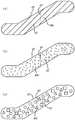
도 3a 내지 도 3f는 본 발명의 검출 시스템의 예시적인 작동 모드들을 나타내는 도면들;
도 4a 내지 도 4c는 승객 수송기의 난간의 전도성 재료의 예시적인 구성들을 나타내는 도면들; 및
도 5는 승객 수송기의 전극들의 대안적인 구성들을 나타내는 도면이다.1 is a perspective view of a passenger vehicle including a machine room housing parts of a drive system of the passenger vehicle;
2 is a block diagram of a detection system for use with a passenger transporter in accordance with one embodiment of the present invention;
3A-3F illustrate exemplary modes of operation of the detection system of the present invention;
4A-4C illustrate exemplary configurations of a conductive material of a balustrade of a passenger transporter; And
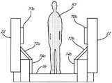
5 shows alternative configurations of the electrodes of a passenger transporter.
본 발명은 에스컬레이터, 무빙 워크 등과 같은 승객 수송기에 관한 탑승객의 위치의 검출에 관한 것이다. 도 1은 제 1 승강장(12), 제 2 승강장(14), 연속한 루프의 스텝들(continuous loop of steps: 16), 핸드레일들(18), 난간들 사이에 승객 탑승 영역을 정의하는 난간(22)들, 구동 시스템(24), 및 기계실(26, 28)들을 포함하는 에스컬레이터(10)의 사시도이다. 스텝들(16)은 제 1 승강장(12)으로부터 제 2 승강장(14)으로 연장된다. 난간(22)들은 제 1 승강장(12)으로부터 제 2 승강장(14)으로 스텝들(16)의 측면을 따라 연장되며, 핸드레일들(18)은 각 난간(22)과 슬라이딩가능하게 맞물린다(slidingly engaged). 구동 시스템(24)은 스텝들(16) 및 핸드레일들(18)을 일정한 속도로 그리고 서로 공시적으로(synchrony) 구동하도록 구성된다. 구동 시스템(24)의 제 1 부분은 기계실(26)에 위치되고, 구동 시스템(24)의 제 2 부분은 기계실(28)에 위치된다.The present invention relates to the detection of a passenger's position relative to a passenger transporter such as an escalator, moving walk, and the like. 1 shows a railing defining a passenger boarding area between a
본 발명은 에스컬레이터(10)에 관한 탑승객의 위치의 검출에 관한 것이다. 어느 주어진 시간에, 탑승객은 에스컬레이터(10)를 따라 탑승하는 동안 난간(22)들 사이의 승객 탑승 영역에 위치될 수 있거나, 에스컬레이터가 움직이지 않아 유지보수 정비(maintenance assistance)를 제공하는 동안 난간(22)들 사이에 또는 기계실(26, 28)들에 위치될 수 있다. 탑승객의 위치에 기초하여, 구동 시스템(24)을 시작 또는 정지시키거나, 효율 및 안전 이유들로 구동 시스템(24)의 시작을 저지하는 것이 바람직할 수 있다. 본 발명은 전기장을 이용하여 에스컬레이터(10)에 관해 탑승객의 위치를 검출하고, 구동 시스템(24)을 시작 또는 정지시켜야 하는지를 결정하기 위해 검출 회로로 그 정보를 전송한다.The present invention relates to the detection of a passenger's position with respect to the
도 2는 본 발명의 일 실시예에 따른 검출 시스템(30)의 블록도이다. 검출 시스템(30)은 [오실레이터(34), 증폭기(36), 모드 선택기(37), 및 임피던스 정합 회로망(impedance matching network: 38)을 포함하는] 구동 회로(32), 용량성 센서(40), 및 검출 회로(42)를 포함한다. 검출 회로(42)는 비교기(44) 및 제어기(45)를 포함하며, 에스컬레이터(10)의 로직 회로(46)와 통신한다.2 is a block diagram of a
제어기(45)는 전기 신호(50)를 발생시키는 오실레이터(34)에 전류를 공급한다. 또한, 제어기(45)로부터의 제어 신호들은 모드 선택기(37)로 보내져, 모드 선택기(37)에게 용량성 센서(40)를 세 가지 모드들: 흡수 모드(absorption mode), 전송 모드(transmission mode), 또는 부하 모드(loading mode) 중 하나로 구동하도록 명령한다.The
오실레이터(34)는 통상적으로 수정-기반(crystal-based) [압전(piezoelectric)] 오실레이터이거나, 제어기(45)의 출력에 의해 직접 구동된다. 오실레이터(34)는 100 ㎑ 내지 1 ㎒ 범위에서 작동할 수 있지만, 100 내지 150 ㎑ 사이에서 작동하는 것이 바람직하다. 오실레이터(34)에 의해 생성된 전기 신호(50)는 500 mW보다 낮은 전력으로 제한되는 저-전력 오실레이팅 구동 신호이다. 전기 신호(50)는 증폭기(36)에 의해 증폭되고, 모드 선택기(37) 및 임피던스 정합 회로망(38)을 거쳐 용량성 센서(40)로 전송되며, 이는 예시적인 실시예에서 1 이상의 버랙터(varactor)들로 구현될 수 있다. 임피던스 정합 회로망(38)은 제어기(45)의 출력에 의해 제어되며, 센서(40)의 가변하는 정전용량에도 불구하고, 전기 신호(50)가 용량성 센서(40)에 효율적으로 전달되는 것을 보장한다. 전기 신호(50)는 용량성 센서(40)의 제 1 전극(54)과 제 2 전극(56) 사이에 정적 전기장(static electric field: 52)을 생성하도록 용량성 센서(40)에 적용된다.Oscillator 34 is typically a crystal-based (piezoelectric) oscillator or is driven directly by the output of
탑승객(57)이 제 1 전극(54)과 제 2 전극(56) 사이에 위치될 때, 준-정적 전기장(quasi-static electric field: 52)에서 섭동(perturbation)이 일어난다. 이 섭동은 검출 회로(42)에 의해 검출가능하다. 검출 회로(42)는 로직 시스템(46)과 통신하는 비교기(44) 및 제어기(45)를 포함한다. 용량성 센서(40)로부터 수신된 출력값에 기초하여, 비교기(44)는 제 1 전극(54)과 제 2 전극(56) 사이의 전압의 차이를 제어기(45)로 출력한다. 제어기(45)는 비교기(44)로부터의 출력을 처리하기 위해 사용되는 알고리즘들을 실행하는 마이크로프로세서이다. 이러한 알고리즘들은 탑승객, 다수의 탑승객, 또는 다른 조건들의 존재를 나타내기 위해 시간에 따른 정전용량의 차이 및 패턴들을 검색하도록, (도 3a 내지 도 3f를 참조하여 아래에 설명되는) 몇몇 실시예들에서 수 개의 검출 모드들을 이용하여 비교기(44)로부터의 출력을 처리한다. 제어기(45)는 로직 시스템(46)과 통신한다. 용량성 센서(40)의 정전용량의 검출된 변화들에 기초하여, 제어기(45) 및 로직 시스템(46)은 (이를테면, 승객 수송기를 시작, 정지 또는 감속하기 위해, 또는 심지어는 승객 수송기의 시작을 저지하기 위해) 승객 수송기의 작동 모드의 변화가 요구되는지를 결정한다.When the
이 시스템은 탑승객의 유전 상수가 공기의 유전 상수보다 훨씬 더 높다는 전제 하에서 작동한다. 정전용량에 대한 수학식은 다음과 같다:The system works on the premise that the passenger's dielectric constant is much higher than the air's dielectric constant. The equation for capacitance is as follows:

여기서,C는 정전용량(패럿)이고,εr은 제 1 전극(54)과 제 2 전극(56) 사이의 물체의 유전 상수[또는 비유전율(relative permittivity)]이며,ε0은 진공의 유전율(8.854x10⁻¹² F/m)이고,A는 제 1 전극(54)과 제 2 전극(56)이 겹쳐진 면적(제곱미터)이며,d는 제 1 전극(54)과 제 2 전극(56) 사이의 거리(미터)이다. 공기의 경우, 유전 상수(εr)는 약 1.00이다. 사람의 경우, 유전 상수(εr)는 다양한 인자들에 따라 대략 60 내지 90이다. 그러므로, 사람이 제 1 전극(54)과 제 2 전극(56) 사이에 있을 때, 용량성 센서(40)의 정전용량은 상당히 변화할 것이다. 이 정전용량의 변화는 검출 회로(42)에 의해 검출될 것이다. (일부 과학 문서들은 0.05x10⁻¹⁸ F만큼 작은 정전용량 변화가 검출될 수 있다는 것을 실험으로 밝혀냈지만) 종이(εr= 3.5) 또는 고무(εr=7)와 같이 공기의 유전 상수에 더 가까운 재료들은 정전용량의 큰 변화를 유도하지 않을 것이며, 따라서 검출되지 않을 수 있다.WhereC is the capacitance (farad),εr is the dielectric constant (or relative permittivity) of the object between the
앞서 언급된 바와 같이, 용량성 센서(40) 및 검출 회로(42)는 세 가지 검출 모드들 중 어느 하나로 작동할 수 있다. 이 모드들은 흡수[또는 션트(shunt)] 모드, 전송 모드, 및 부하 모드이다. 도 3a 내지 도 3f는 이러한 세 가지 검출 모드들을 더 자세히 나타낸 도면이다.As mentioned above, the
도 3a 및 도 3b는 흡수 모드에서의 용량성 센서(40)를 나타낸다. 제 1 전극(54)은 제 2 전극(56)을 향해 전기장(예를 들어, 준-정적 전기장: 52)을 생성한다. 제 1 전극(54)과 제 2 전극(56) 사이에 아무도 존재하지 않을 때, 제 2 전극(56)은 정상 상태 세기(steady-state intensity)로 전기장(52)을 수용한다[전기장(52)의 일부분은 접지로 션트된다]. 도 3b에 도시된 바와 같이, (탑승객 또는 다른 물체와 같은) 몸체(57)가 제 1 전극(54)과 제 2 전극(56) 사이에 존재할 때, 전기장(52)이 섭동되어, 전기장(52)의 일부분이 몸체(57)를 통해 션트되어 접지되고 제 2 전극에 도달하지 않음에 따라, 제 2 전극(56)은 더 약한 전기장(52)을 수용한다.3A and 3B show
도 3c 및 도 3d는 전송 모드의 용량성 센서(40)를 나타낸다. 제 1 전극(54)은 제 2 전극(56)을 향해 전기장(예를 들어, 준-정적 전기장: 52)을 생성한다[전기장(52)의 일부분은 접지로 션트된다]. 제 1 전극(54)과 제 2 전극(56) 사이에 아무도 존재하지 않을 때, 제 1 전극(54)과 제 2 전극(56) 사이의 정전용량은 고정된 값을 갖는다. 도 3d에 도시된 바와 같이, (탑승객 또는 다른 물체와 같은) 몸체(57)가 제 1 전극(54)과 제 2 전극(56) 사이에 존재할 때, 전기장 생성기(field producer)는 서로 용량성으로 커플링된(capacitively coupled to one another) 제 1 전극(54)과 몸체(57)의 조합이 되며, 이 전기장 생성기와 제 2 전극(56) 사이의 정전용량은 몸체(57)의 위치 및 특성에 따라 변한다.3C and 3D
도 3e 및 도 3f는 부하 모드의 용량성 센서(40)를 나타낸다. 제 1 전극(54)은 전기장(예를 들어, 준-정적 전기장: 52)을 생성하고, 이 중 적어도 일부분은 접지로 션트된다[이 모드에서는 제 2 전극(56)이 용량성 센서로서 작용하지 않는다]. 도 3f에 도시된 바와 같이, (탑승객 또는 다른 물체와 같은) 몸체(57)가 제 1 전극(54)에 인접하여(즉, 제 1 전극(54)과 제 2 전극(56) 사이에) 존재할 때, 전기장(52)이 섭동되고 몸체(57)를 통해 접지로 션트되므로, 몸체(57)의 위치 및 특성에 기초하여 제 1 전극(54)과 몸체(57) 사이의 정전용량에 따라 변하는 검출가능한 부하 효과를 유도한다. 또한, 제 2 전극(56)이 제 1 전극(54) 대신 또는 이에 추가로 이 모드에서 전기장을 생성할 수 있다.3E and 3F show
승객 수송기에서 이 기술의 사용을 위한 적어도 두 가지 적용들이 존재한다: 에스컬레이터(10)[특히, 난간(22)들 사이]에 있는 탑승객을 검출하고, 기계실(26, 28) 내에 있는 탑승객을 검출한다. 앞서 설명되고 도 2에 도시된 회로는 용량성 센서(40)의 실현에 있어 약간의 변동들을 가지고 이 두 적용들에 모두 적용할 수 있다. 검출된 탑승객이 에스컬레이터(10)의 승객일 때, 난간(22)들은 용량성 센서(40)의 제 1 및 제 2 전극들(54, 56)을 형성 또는 지지한다. 검출된 탑승객이 기계실(26, 28)의 유지보수 직원인 경우, 감지 와이어가 제 1 전극(54)으로서 작용하고, 접지 기계(grounded machinery)가 제 2 전극(56)으로서 작용하여, 용량성 센서(40)를 형성한다. 이러한 적용들 각각의 구체적인 내용들은 아래에 더 자세히 설명될 것이다.There are at least two applications for the use of this technique in passenger transport: detecting passengers in escalators 10 (particularly between handrails 22) and detecting passengers in
용량성 센서(40)를 형성하는 난간(22)들을 갖는, 승객 수송기의 난간(22)들 사이의 탑승객을 검출하기 위해, 전도성 재료가 각각의 난간(22)에 적용되어, 용량성 센서(40)를 형성한다. 이는 특히 유리 표면들과 같이 비-전도성 표면들을 갖는 난간(22)들에 적용할 수 있다. 전도성 재료가 난간(22)들의 비-전도성 표면들을 둘러싸는 여하한의 금속 부분들로부터 충분히 멀리 이격되는 것이 중요한데, 이는 이러한 금속 부분들이 본질적으로 접지로 작용하기 때문이다. 전도성 재료가 금속 부분들에 너무 가까이 있으면, 전기 신호들은 접지로 작용할 수 있는 이러한 금속 부분들로 션트될 수 있음에 따라, 검출 시스템의 감도 및 범위가 줄어들 수 있다. 하지만, 필요한 회로 연결들을 만들기 위해 검출 시스템의 제한된 수의 작은 부분들이 난간의 전도성 부분들에 가까이 있는 것이 허용될 수 있다.In order to detect passengers between the
도 4a 내지 도 4c는 용량성 센서(40)를 생성하기 위해 전도성 재료(60)가 난간(22)의 비-전도성 표면(62)에 적용될 수 있는 예시적인 몇몇 방식들을 나타내는 도면들이다. 도 4a는 그물형(mesh) 또는 투명한 전도성 막(60a)이 난간(22)의 비-전도성 표면(62)에 라미네이트된(laminated) 일 실시예를 나타낸다. 이 그물형 또는 투명한 전도성 막(60a)은 비-전도성 표면(62)의 제조 시에 적용될 수 있거나, 기존의 승객 수송기에 새로 장착(retro-fit)하기 위해 이후 비-전도성 표면(62)에 적용될 수 있다. 도 4b는 유리 자체가 유리 제조 공정 시에 형성된 전도성 요소들(60b)을 포함하는 일 실시예를 나타낸다. 도 4c는 전도성 데칼들(conductive decals: 60c)이 비-전도성 표면(62)에 부착된 일 실시예를 나타낸다. 각 난간(22)의 비-전도성 표면(62)에 전도성 재료(60)를 적용하기 위해 다른 방법들이 사용될 수 있지만, 전도성 재료(60)가 비-전도성 표면(62)을 둘러싸는 금속 부분들 중 어느 부분에 너무 가까이 있지 않는 것이 중요하며, 이는 이러한 금속 부분들이 본질적으로 접지로서 작용하기 때문이다. 전도성 재료(60)가 이러한 접지되는 영역들에 너무 가까이 있으면, 신호가 이러한 접지되는 영역들로 션트될 수 있으며, 이는 감소된 감도 및 범위를 유도할 것이다. 난간(22)이 금속성인 적용들에 대해서는, 반대쪽 난간(22)으로부터 절연될 필요가 있을 것이다.4A-4C illustrate some exemplary ways in which conductive material 60 may be applied to
앞서 설명된 바와 같이, 탑승객이 난간(22)들에 가까이 있거나, 이 사이에 있을 때, 난간(22)들의 영역[더 상세하게는, 난간(22)들에 배치된 전도성 재료(60)의 표면 영역]은 정전용량(및 이에 따른 검출 감도)의 변화에 직접적인 영향을 준다. 더 긴 에스컬레이터들에서, 전도성 표면의 길이는 다소 공명(resonant)할 수 있으며, 안테나처럼 작용할 수 있다. 이러한 경우들에서, 전파되는 전기장은 난간(22)들에 존재할 수 있으며, 둘러싸인 전자 디바이스들을 방해할 수 있다. 이러한 적용들에서, 선택적인 분리 라인(63)에 의해 예시된 바와 같이, 전도성 표면(60)은 난간(22)의 각 내부 표면에서 2 이상의 부분들로 분할될 수 있다. 검출 회로(42)에 다중화기를 추가하면, 다수의 부분들이 검출 회로(42)의 다른 구성요소들과 통신할 수 있을 것이다. 대안적으로, 이러한 부분들을 제어기(46)와 통신시키기 위해 다수의 비교기들(44)이 사용될 수 있다.As described above, when the passenger is near or in between the
작동 시, 에스컬레이터(10)에 탑승객의 존재로 정전용량의 변화가 용량성 센서(40)에 의해 검출되면, 검출 회로(42)는 에스컬레이터(10)의 작동을 변화시켜야 하는지를 결정할 수 있다. 예를 들어, 탑승객이 에스컬레이터(10)에 접근하여 난간(22)들 사이의 공간에 들어감에 따라, 에스컬레이터(10)는 저전력 또는 에너지 절약모드에서 벗어나 "웨이크 업(wake up)"될 수 있으며, 즉시 또는 더 낮은 속도로부터 점차적으로 정기 운송 모드(regular transport mode)에 들어갈 수 있다. 탑승객이 에스컬레이터(10)에 탑승하고 있는 중에 긴급상황이 발생한 경우, 에스컬레이터(10)는 급작스럽게 멈추는 것을 방지하기 위해 완만한 정지 모드(gentle stop mode)에 들어갈 수 있다. 또한, 탑승객이 정지된 에스컬레이터(10)에 위치되는 경우, 에스컬레이터(10)의 시작을 회피하기 위해 탑승객의 검출이 사용될 수 있다.In operation, if a change in capacitance is detected by the
또한, 검출 시스템(30)은 기계실(26, 28)들에 있는 탑승객을 검출하기 위해 사용될 수 있다. 기계실(26, 28)들은 각각 (도 1에 도시된 바와 같이) 스텝들(16) 및 난간(22)에 인접하게 위치된다. 기계실(26, 28)들에 있는 탑승객을 검출하기 위하여, 구동 시스템(24) 및/또는 각 기계실(26, 28) 내의 다른 전도성 구성요소들이 접지된다. 감지 와이어(도시되지 않음)가 기계실(26, 28)에 (바람직하게는, 중간 높이에) 설치되며, 제 1 전극(54)을 형성하도록 접지-격리된다(ground-isolated). 접지 구성요소들은 제 2 전극(56)을 형성한다. 또한, 도 2에 대해 앞서 설명된 동일한 회로가 기계실 적용을 위해 전기장(52)을 생성하는데 사용된다.In addition, the
기계실(26)에 아무도 존재하지 않을 때에는, 감지 와이어 및 구동 시스템(24)과 같은 접지 요소들 사이의 정전용량이 일정하다. 탑승객 또는 다른 물체가 기계실(26)에 들어가는 경우, 탑승객 및 공기의 유전율 또는 유전 상수 간의 차이로 인해 감지 와이어 및 구동 시스템(24)과 같은 접지 요소들 사이의 정전용량이 변화된다. 이 정전용량의 변화는 도 2를 참조하여 앞서 설명된 것과 동일하거나 유사한 방식으로 검출 회로(42)에 의해 검출된다. 탑승객이 기계실(26)에서 검출된 경우, 에스컬레이터(10)의 작동이 중단된다(disabled)(즉, 부분들이 이동하지 않는 것을 보장하기 위해 모터에 모든 전력을 차단한다).When no one is in the
(부연하면, 난간 사이에 또는 기계실에 용량성 센서를 생성하는) 이러한 두 개의 적용들 각각은 도 2에 도시된 바와 같이 구성된 별도의 회로를 사용할 수 있거나, 회로를 공유할 수 있다. 또한, 정해진 조건들(예를 들어, 온도 및 습도)에서의 변화들이 가질 수 있는, 정전용량 감지 구성에 있어서의 유해한 영향을 피하기 위해, 해당 기술 분야에 잘 알려진 추가적인 회로 및 센서들이 포함될 수 있다.Each of these two applications (in other words, creating a capacitive sensor between handrails or in a machine room) may use a separate circuit configured as shown in FIG. 2, or may share a circuit. In addition, additional circuitry and sensors that are well known in the art may be included to avoid the detrimental effects on the capacitive sensing configuration that changes in defined conditions (eg, temperature and humidity) may have.
도 5는 본 발명의 검출 시스템을 구현하기 위한 승객 수송기의 전극들의 대안적인 구성들을 나타내는 도면이다. 제 1 전극(54) 및 제 2 전극(56)(도 2)은 [위치들(70a 및 70b)에 도시된 바와 같은] 난간(22)들에 위치될 수 있거나, [위치들(72a 및 72b)에 도시된 바와 같은] 승객 수송기의 내부 데킹(inner decking)에 위치될 수 있거나, [위치들(74a 및 74b)에 도시된 바와 같은] 승객 수송기의 내부 스커트(inner skirt)에 위치될 수 있거나, 이러한 위치들 중 1 이상의 조합에 위치될 수 있다. 이러한 구성들 중 어느 구성에서 검출 시스템의 용량성 감지 기능을 달성하기 위해, 전극들의 적합한 전기적 격리가 요구된다. 예시적인 실시예에서는, (접지와 같은) 고정된 전위에 전기적으로 격리된 연결을 제공하기 위해 스텝들(16), 또는 스텝들(16) 및 그들의 동반 스텝 체인들이 사용되며, 검출의 앞서 설명된 부하 모드를 구현하기 위해 전극이 연결된다.5 shows alternative configurations of the electrodes of a passenger transporter for implementing the detection system of the present invention.
본 발명은 예시적인 실시예(들)를 참조하여 설명되었지만, 당업자라면 본 발명의 범위를 벗어나지 않고 다양한 변경들이 행해질 수 있으며, 이의 요소들에 대해 등가물들로 대체될 수 있음을 이해할 것이다. 또한, 본 발명은 본 발명의 본질적인 범위를 벗어나지 않고 본 발명의 내용에 대해 특정한 상황 또는 재료를 적용하기 위해 다수의 변형들이 행해질 수 있다. 그러므로, 본 발명은 개시된 특정 실시예(들)로 제한되는 것이 아니라, 첨부된 청구항들의 범위에 속하는 모든 실시예들을 포함하는 것으로 의도된다.Although the present invention has been described with reference to exemplary embodiment (s), those skilled in the art will understand that various changes may be made and equivalents may be substituted for elements thereof without departing from the scope of the present invention. In addition, many modifications may be made to adapt a particular situation or material to the teachings of the invention without departing from the essential scope thereof. Therefore, it is intended that the invention not be limited to the particular embodiment (s) disclosed, but to include all embodiments falling within the scope of the appended claims.
Claims (24)
Translated fromKorean오실레이팅 구동 신호(oscillating drive signal)를 공급하기 위한 구동 회로;
상기 오실레이팅 구동 신호에 응답하여 제 2 전극을 향해 전기장을 생성하도록 구성된 제 1 전극을 갖는 용량성 센서(capacitive sensor);
상기 용량성 센서의 정전용량(capacitance)의 변화를 감지하고, 정전용량의 함수로서 출력을 생성하는 상기 용량성 센서에 연결된 검출 회로; 및
상기 승객 수송기의 작동 모드를 선택적으로 조정하기 위해 상기 검출 회로 출력에 응답하는 제어기를 포함하고,
정전용량의 변화는 상기 제 1 및 제 2 전극들 사이의 전기장에서 탑승객의 존재에 의해 유도되는 탑승객 검출 시스템.A system for detecting a passenger with respect to a passenger transporter having structural components and a passenger boarding area, the system comprising:
A drive circuit for supplying an oscillating drive signal;
A capacitive sensor having a first electrode configured to generate an electric field toward a second electrode in response to the oscillating drive signal;
Detection circuitry coupled to the capacitive sensor that senses a change in capacitance of the capacitive sensor and generates an output as a function of capacitance; And
A controller responsive to the detection circuit output for selectively adjusting an operation mode of the passenger vehicle,
The change in capacitance is induced by the presence of a passenger in an electric field between the first and second electrodes.
상기 제 1 및 제 2 전극들은 상기 승객 탑승 영역의 반대쪽 측면에 있는 상기 승객 수송기의 구조적 구성요소의 부분들에 배치되는 탑승객 검출 시스템.The method according to claim 1,
And the first and second electrodes are disposed in portions of the structural component of the passenger transporter on an opposite side of the passenger boarding area.
상기 제 1 전극은 상기 승객 탑승 영역의 제 1 측면에 있는 상기 승객 수송기의 구조적 구성요소에 배치된 전도성 재료를 포함하고, 상기 제 2 전극은 상기 제 1 전극의 반대쪽에 있는 상기 승객 탑승 영역의 제 2 측면에 있는 상기 승객 수송기의 구조적 구성요소에 배치된 전도성 재료를 포함하는 탑승객 검출 시스템.The method according to claim 1,
The first electrode comprises a conductive material disposed on the structural component of the passenger transporter on the first side of the passenger boarding area, and the second electrode is formed on the first side of the passenger boarding area opposite the first electrode; Passenger detection system comprising a conductive material disposed in the structural component of the passenger transporter on two sides.
상기 승객 수송기의 구조적 구성요소는 난간이고, 상기 제 1 전극은 상기 승객 탑승 영역의 일 측면에 상기 난간의 전도성 표면을 포함하며, 상기 제 2 전극은 상기 승객 탑승 영역의 반대쪽 측면에 상기 난간의 전도성 표면을 포함하는 탑승객 검출 시스템.The method according to claim 1,
The structural component of the passenger transporter is a railing, the first electrode comprises a conductive surface of the railing on one side of the passenger boarding area, and the second electrode is conductive of the railing on an opposite side of the passenger boarding area. Passenger detection system comprising a surface.
상기 난간은 비-전도성 재료로 형성되고, 전도성 재료는 상기 승객 탑승 영역의 반대쪽 측면들의 일 표면에 배치되는 탑승객 검출 시스템.5. The method of claim 4,
The handrail is formed of a non-conductive material, and the conductive material is disposed on one surface of opposite sides of the passenger boarding area.
상기 비-전도성 재료는 유리인 탑승객 검출 시스템.6. The method of claim 5,
And the non-conductive material is glass.
상기 전도성 재료는 상기 비-전도성 난간의 표면에 부착되는 탑승객 검출 시스템.6. The method of claim 5,
The conductive material is attached to a surface of the non-conductive railing.
상기 전도성 재료는 상기 비-전도성 재료 난간과 일체로 형성되는 탑승객 검출 시스템.6. The method of claim 5,
The conductive material is integrally formed with the non-conductive material railing.
상기 전도성 재료는 다수의 영역들로 분리되는 탑승객 검출 시스템.6. The method of claim 5,
And the conductive material is separated into a plurality of regions.
다중화기가 상기 용량성 센서의 출력을 상기 검출 회로에 전송하기 위해 상기 다수의 영역들에 연결되는 탑승객 검출 시스템.The method of claim 9,
A passenger detection system, wherein a multiplexer is coupled to the plurality of areas to send the output of the capacitive sensor to the detection circuit.
상기 제 1 전극은 상기 승객 수송기의 기계실에 위치된 감지 와이어를 포함하고, 상기 제 2 전극은 상기 기계실 내의 접지 구성요소(grounded component)를 포함하는 탑승객 검출 시스템.The method according to claim 1,
The first electrode comprises a sensing wire located in a machine room of the passenger transporter, and the second electrode comprises a grounded component in the machine room.
상기 구동 회로는,
오실레이팅 구동 신호를 생성하는 오실레이터;
상기 오실레이팅 구동 신호를 증폭시키도록 상기 오실레이터에 연결된 증폭기;
상기 증폭기와 상기 용량성 센서 사이에 연결된 임피던스 정합 회로망(impedance matching network); 및
상기 용량성 센서를 선택 모드로 구동하도록 작동가능한 모드 선택기를 더 포함하는 탑승객 검출 시스템.The method according to claim 1,
Wherein the driving circuit comprises:
An oscillator for generating an oscillating drive signal;
An amplifier coupled to the oscillator to amplify the oscillating drive signal;
An impedance matching network coupled between the amplifier and the capacitive sensor; And
And a mode selector operable to drive the capacitive sensor in a selection mode.
상기 오실레이터는 100 ㎑ 내지 1 ㎒의 주파수를 갖는 탑승객 검출 시스템.13. The method of claim 12,
The oscillator having a frequency of 100 Hz to 1 MHz.
상기 오실레이터는 100 ㎑ 내지 150 ㎑의 주파수를 갖는 탑승객 검출 시스템.13. The method of claim 12,
The oscillator having a frequency of 100 Hz to 150 Hz.
상기 검출 회로는,
상기 용량성 센서의 정전용량의 변화를 감지하고, 상기 용량성 센서의 정전용량의 함수로서 출력을 생성하도록 구성된 비교기를 더 포함하는 탑승객 검출 시스템.The method according to claim 1,
Wherein the detection circuit comprises:
And a comparator configured to sense a change in capacitance of the capacitive sensor and to generate an output as a function of the capacitance of the capacitive sensor.
상기 제 1 난간의 제 1 전극에 전기 신호를 공급하여, 상기 제 1 전극, 및 상기 제 1 난간의 반대쪽에 있는 상기 제 2 난간의 제 2 전극 사이에 전기장을 생성하는 단계;
상기 제 1 및 제 2 전극들 사이의 정전용량의 변화를 검출하는 단계; 및
정전용량의 검출된 변화의 함수로서, 상기 승객 수송기의 작동을 제어하는 단계를 포함하고,
정전용량의 변화는 상기 제 1 및 제 2 전극들 사이의 전기장의 탑승객의 존재에 의해 유도되는 검출 방법.A method for detecting a passenger between first and second railings of a passenger transporter, the method comprising:
Supplying an electrical signal to a first electrode of the first railing to generate an electric field between the first electrode and a second electrode of the second railing opposite the first railing;
Detecting a change in capacitance between the first and second electrodes; And
Controlling the operation of the passenger vehicle as a function of the detected change in capacitance,
The change in capacitance is induced by the presence of a passenger in an electric field between the first and second electrodes.
상기 제 1 전극은 상기 제 1 난간의 표면에 배치된 전도성 재료를 포함하고, 상기 제 2 전극은 상기 제 2 난간의 표면에 배치된 전도성 재료를 포함하는 검출 방법.17. The method of claim 16,
And the first electrode comprises a conductive material disposed on the surface of the first railing, and the second electrode comprises a conductive material disposed on the surface of the second railing.
상기 기계실에 위치된 감지 와이어에 전기 신호를 전송하여, 상기 감지 와이어로부터 전기적으로 격리된 상기 기계실 내의 전도성 구성요소와 상기 감지 와이어 사이에 전기장을 생성하는 단계;
상기 감지 와이어와 상기 전도성 구성요소 사이의 정전용량의 변화를 검출하는 단계; 및
정전용량의 검출된 변화의 함수로서, 상기 승객 수송기의 작동을 제어하는 단계를 포함하는 검출 방법.A method for detecting a passenger in a machine room of a passenger transporter,
Transmitting an electrical signal to a sense wire located in the machine room to generate an electric field between the conductive wire and the sense wire in the machine room electrically isolated from the sense wire;
Detecting a change in capacitance between the sense wire and the conductive component; And
Controlling the operation of the passenger transport as a function of the detected change in capacitance.
상기 정전용량의 변화는 상기 감지 와이어와 상기 전도성 구성요소 사이의 전기장의 탑승객의 존재에 의해 유도되는 검출 방법.22. The method of claim 21,
Wherein the change in capacitance is induced by the presence of a passenger in an electric field between the sensing wire and the conductive component.
상기 전기 신호는 저전력 오실레이팅 구동 신호인 검출 방법.The method of claim 16 or 21,
The electrical signal is a low power oscillating drive signal.
상기 전기 신호는 100 ㎑ 내지 1 ㎒의 주파수를 갖는 검출 방법.The method of claim 16 or 21,
The electrical signal has a frequency of 100 Hz to 1 MHz.
Applications Claiming Priority (1)
| Application Number | Priority Date | Filing Date | Title |
|---|---|---|---|
| PCT/US2009/068805WO2011075146A1 (en) | 2009-12-18 | 2009-12-18 | Detection of people relative to a passenger conveyor with a capacitive sensor |
Publications (2)
| Publication Number | Publication Date |
|---|---|
| KR20120099086A KR20120099086A (en) | 2012-09-06 |
| KR101386545B1true KR101386545B1 (en) | 2014-04-17 |
Family
ID=44167631
Family Applications (1)
| Application Number | Title | Priority Date | Filing Date |
|---|---|---|---|
| KR1020127016610AExpired - Fee RelatedKR101386545B1 (en) | 2009-12-18 | 2009-12-18 | Detection of people relative to a passenger conveyor with a capacitive sensor |
Country Status (8)
| Country | Link |
|---|---|
| US (1) | US9272882B2 (en) |
| EP (1) | EP2512970B1 (en) |
| JP (1) | JP5681206B2 (en) |
| KR (1) | KR101386545B1 (en) |
| CN (1) | CN102666353B (en) |
| BR (1) | BR112012014183A2 (en) |
| RU (1) | RU2533653C2 (en) |
| WO (1) | WO2011075146A1 (en) |
Cited By (1)
| Publication number | Priority date | Publication date | Assignee | Title |
|---|---|---|---|---|
| JP2013514244A (en)* | 2009-12-18 | 2013-04-25 | オーチス エレベータ カンパニー | Detection of people associated with passenger conveyors with capacitive sensors |
Families Citing this family (14)
| Publication number | Priority date | Publication date | Assignee | Title |
|---|---|---|---|---|
| FI125399B (en)* | 2010-11-02 | 2015-09-30 | Kone Corp | Steering arrangements for the control of a passenger conveyor |
| MX373880B (en)* | 2013-12-20 | 2020-03-26 | Inventio Ag | Arrangement of a monitoring sensor in an escalator or in a moving walkway |
| US9896309B2 (en)* | 2014-05-06 | 2018-02-20 | Otis Elevator Company | Object detector, and method for controlling a passenger conveyor system using the same |
| FI125862B (en)* | 2015-01-28 | 2016-03-15 | Kone Corp | Electronic safety device and conveyor system |
| EP3088346A1 (en)* | 2015-04-27 | 2016-11-02 | Thyssenkrupp Elevator Innovation Center, S.A. | Safety device and method for preventing accidents in the combplate area of escalators or moving walkways |
| US10183667B2 (en) | 2015-09-15 | 2019-01-22 | Deere & Company | Human presence detection on a mobile machine |
| EP3205618B1 (en)* | 2016-02-15 | 2024-04-03 | TK Escalator Norte, S.A. | Method for controlling a transport device, namely an escalator or a moving walkway |
| US11064768B2 (en) | 2016-03-15 | 2021-07-20 | Nike, Inc. | Foot presence signal processing using velocity |
| US11357290B2 (en) | 2016-03-15 | 2022-06-14 | Nike, Inc. | Active footwear sensor calibration |
| KR102494900B1 (en) | 2016-03-15 | 2023-02-01 | 나이키 이노베이트 씨.브이. | Capacitive Foot Presence Detection for Footwear |
| US11026481B2 (en) | 2016-03-15 | 2021-06-08 | Nike, Inc. | Foot presence signal processing using velocity |
| EP3309108B1 (en) | 2016-10-14 | 2020-03-25 | Otis Elevator Company | People conveyor and method of operating a people conveyor |
| US10351392B1 (en)* | 2018-10-23 | 2019-07-16 | Otis Elevator Company | Escalator and moving walkway system with safety sensor |
| JP6786673B1 (en)* | 2019-07-10 | 2020-11-18 | 東芝エレベータ株式会社 | Passenger conveyor |
Citations (3)
| Publication number | Priority date | Publication date | Assignee | Title |
|---|---|---|---|---|
| KR19990072176A (en)* | 1996-10-17 | 1999-09-27 | 요트.게.아. 롤페즈 | Position indicator |
| KR100510420B1 (en) | 2001-12-18 | 2005-08-26 | 도시바 엘리베이터 가부시키가이샤 | Passenger conveyor apparatus |
| JP2006193258A (en)* | 2005-01-12 | 2006-07-27 | Toshiba Elevator Co Ltd | Passenger conveyor |
Family Cites Families (41)
| Publication number | Priority date | Publication date | Assignee | Title |
|---|---|---|---|---|
| DE2060357A1 (en) | 1970-12-08 | 1972-06-22 | Rheinstahl Eggers Kehrhahn | Arrangement for the control of a travel conveyor, in particular an escalator |
| JPS57141377A (en)* | 1981-02-27 | 1982-09-01 | Hitachi Ltd | Driving device for man conveyor |
| US4457113A (en) | 1982-02-24 | 1984-07-03 | Super-Cut, Inc. | Protected super-abrasive grinding tool |
| US4796013A (en)* | 1985-10-18 | 1989-01-03 | Aisin Seiki Kabushiki Kaisha | Capacitive occupancy detector apparatus |
| JPH01317987A (en) | 1988-06-15 | 1989-12-22 | Mitsubishi Electric Corp | Passenger detection device for passenger conveyor |
| US5844415A (en) | 1994-02-03 | 1998-12-01 | Massachusetts Institute Of Technology | Method for three-dimensional positions, orientation and mass distribution |
| EP0824799B1 (en) | 1995-05-08 | 2002-08-21 | Massachusetts Institute Of Technology | System for non-contact sensing and signalling using human body as signal transmission medium |
| AUPN605295A0 (en)* | 1995-10-18 | 1995-11-09 | Loderway Pty. Limited | Systems for the conveyance of standing passengers |
| US6368469B1 (en) | 1996-05-09 | 2002-04-09 | Applied Materials, Inc. | Coils for generating a plasma and for sputtering |
| US5704464A (en)* | 1996-06-28 | 1998-01-06 | Otis Elevator Company | Passenger sensor for an escalator or moving walk |
| US5842554A (en)* | 1996-07-31 | 1998-12-01 | Otis Elevator Company | Passenger sensor for a conveyor |
| US5785165A (en)* | 1996-10-30 | 1998-07-28 | Otis Elevator Company | Data collection and analysis system for passenger conveyors |
| MY118807A (en) | 1996-12-16 | 2005-01-31 | Inventio Ag | Device for monitoring the entry area of an escalator or moving walkway |
| US6158768A (en)* | 1998-02-20 | 2000-12-12 | Trw Vehicle Safety Systems Inc. /Trw Inc. | Apparatus and method for discerning certain occupant characteristics using a plurality of capacitive sensors |
| US6249130B1 (en)* | 1998-12-21 | 2001-06-19 | Agrichem, Inc. | Shielded flat-plate proximity/dielectric properties sensor |
| US6373235B1 (en)* | 1999-05-04 | 2002-04-16 | Clifford A. Barker | Apparatus and method for determining the position and motion of an object and for precise measurement of phase-related values |
| EP1097898B1 (en)* | 1999-05-17 | 2005-10-05 | Mitsubishi Denki Kabushiki Kaisha | Controller of passenger conveyor and passenger sensor |
| DE10164873B4 (en) | 2001-07-31 | 2005-12-01 | Kone Corp. | Safety device for passenger conveyor systems |
| DE20122277U1 (en) | 2001-07-31 | 2004-11-18 | Kone Corp. | Safety device for escalator or moving walkway uses capacitive sensors for detecting presence of persons or objects |
| US6700393B2 (en)* | 2001-10-17 | 2004-03-02 | Delphi Technologies, Inc. | Capacitive sensor assembly for use in a non-contact obstacle detection system |
| ES2327035T3 (en) | 2002-05-23 | 2009-10-23 | Ident Technology Ag | SYSTEM AND PROCEDURE TO ANALYZE THE PRESENCE OF OBJECTS. |
| JP4067525B2 (en)* | 2002-09-13 | 2008-03-26 | オーチス エレベータ カンパニー | Safety monitoring for human transport |
| JP2004184288A (en)* | 2002-12-04 | 2004-07-02 | Nissin Electric Co Ltd | Object detection device |
| JP4401138B2 (en)* | 2003-10-10 | 2010-01-20 | 東芝エレベータ株式会社 | Passenger conveyor |
| US7116117B2 (en)* | 2004-02-16 | 2006-10-03 | Honda Motor Co., Ltd. | Capacitive sensor |
| US20060071774A1 (en)* | 2004-02-26 | 2006-04-06 | Brown Katherine A | Item monitoring system and methods using an item monitoring system |
| WO2005089473A2 (en) | 2004-03-18 | 2005-09-29 | Advanced Lighting Technologies, Inc. | Method for generating a discharge in high pressure gases |
| US7518443B2 (en)* | 2004-09-10 | 2009-04-14 | Quantum Applied Science & Research, Inc. | Amplifier circuit and method for reducing voltage and current noise |
| WO2006056424A2 (en) | 2004-11-23 | 2006-06-01 | Ident Technology Ag | Closing arrangement |
| JP2006176327A (en) | 2004-12-24 | 2006-07-06 | Toshiba Elevator Co Ltd | Handrail device of passenger conveyor and operation stopping method in case of handle damage |
| JP2007131411A (en) | 2005-11-10 | 2007-05-31 | Hitachi Ltd | Passenger conveyor control system |
| CN101078774B (en)* | 2006-05-26 | 2012-07-18 | 株式会社藤仓 | Proximity sensor and proximity sensing method |
| KR101487295B1 (en)* | 2006-11-27 | 2015-01-28 | 마이크로칩 테크놀로지 저머니 Ⅱ 게엠베하 운트 콤파니 카게 | Arrangement for the detection of body parts by absorbing an electric near field |
| DE102007058707A1 (en)* | 2007-12-06 | 2009-06-10 | Infineon Technologies Ag | Capacity sensor for detecting presence of person or object in seat, for automobile's intelligent airbag system, has evaluation circuit coupled with receiver circuit to determine capacitive value based on received frequency bridging signals |
| US20090223578A1 (en)* | 2008-03-07 | 2009-09-10 | Joel Gulbranson | Flush-mounted capacitive sensor mount |
| ITBO20080392A1 (en)* | 2008-06-20 | 2009-12-21 | Alberto Bauer | CAPACITIVE SENSOR TO DETECT AN ELECTRIC FIELD GENERATED BY A CONDUCTOR |
| DE102008035627A1 (en)* | 2008-07-31 | 2010-02-11 | Gerd Reime | Device for the capacitive measurement of changes |
| US8610009B2 (en)* | 2008-10-22 | 2013-12-17 | Atmel Corporation | Capacitive touch sensors |
| CN103925935B (en)* | 2009-05-13 | 2017-07-07 | 辛纳普蒂克斯公司 | Capacitive sensor means |
| JP4766166B2 (en)* | 2009-09-30 | 2011-09-07 | 株式会社デンソー | Capacitance type occupant sensor and capacitance type occupant sensor device |
| KR101386545B1 (en)* | 2009-12-18 | 2014-04-17 | 오티스 엘리베이터 컴파니 | Detection of people relative to a passenger conveyor with a capacitive sensor |
- 2009
- 2009-12-18KRKR1020127016610Apatent/KR101386545B1/ennot_activeExpired - Fee Related
- 2009-12-18CNCN200980162888.6Apatent/CN102666353B/enactiveActive
- 2009-12-18EPEP09852403.6Apatent/EP2512970B1/enactiveActive
- 2009-12-18JPJP2012544465Apatent/JP5681206B2/ennot_activeExpired - Fee Related
- 2009-12-18WOPCT/US2009/068805patent/WO2011075146A1/enactiveApplication Filing
- 2009-12-18BRBR112012014183Apatent/BR112012014183A2/ennot_activeIP Right Cessation
- 2009-12-18USUS13/515,446patent/US9272882B2/enactiveActive
- 2009-12-18RURU2012121841/11Apatent/RU2533653C2/ennot_activeIP Right Cessation
Patent Citations (3)
| Publication number | Priority date | Publication date | Assignee | Title |
|---|---|---|---|---|
| KR19990072176A (en)* | 1996-10-17 | 1999-09-27 | 요트.게.아. 롤페즈 | Position indicator |
| KR100510420B1 (en) | 2001-12-18 | 2005-08-26 | 도시바 엘리베이터 가부시키가이샤 | Passenger conveyor apparatus |
| JP2006193258A (en)* | 2005-01-12 | 2006-07-27 | Toshiba Elevator Co Ltd | Passenger conveyor |
Cited By (1)
| Publication number | Priority date | Publication date | Assignee | Title |
|---|---|---|---|---|
| JP2013514244A (en)* | 2009-12-18 | 2013-04-25 | オーチス エレベータ カンパニー | Detection of people associated with passenger conveyors with capacitive sensors |
Also Published As
| Publication number | Publication date |
|---|---|
| EP2512970A1 (en) | 2012-10-24 |
| BR112012014183A2 (en) | 2016-05-31 |
| RU2012121841A (en) | 2014-01-27 |
| CN102666353B (en) | 2014-09-10 |
| US9272882B2 (en) | 2016-03-01 |
| JP5681206B2 (en) | 2015-03-04 |
| EP2512970B1 (en) | 2017-09-13 |
| JP2013514244A (en) | 2013-04-25 |
| RU2533653C2 (en) | 2014-11-20 |
| KR20120099086A (en) | 2012-09-06 |
| US20120247919A1 (en) | 2012-10-04 |
| CN102666353A (en) | 2012-09-12 |
| EP2512970A4 (en) | 2015-10-14 |
| WO2011075146A1 (en) | 2011-06-23 |
Similar Documents
| Publication | Publication Date | Title |
|---|---|---|
| KR101386545B1 (en) | Detection of people relative to a passenger conveyor with a capacitive sensor | |
| US8727095B2 (en) | Conveyor equipment | |
| KR101179088B1 (en) | Equipment for monitoring the space in front of escalators and moving walkways by high-frequency sensors | |
| EP0915805B1 (en) | Passenger sensor for a conveyor | |
| US8708130B2 (en) | Start-up sensor with entrance way monitoring for escalators or moving walkways | |
| US9181066B2 (en) | Passenger conveyor | |
| JP2018141352A (en) | Door control method and control device | |
| JP5795088B2 (en) | Passenger conveyor | |
| JP2007210710A (en) | Passenger conveyor | |
| HK1175764A (en) | Detection of people relative to a passenger conveyor with a capacitive sensor | |
| JP2004099266A (en) | Passenger conveyor | |
| KR20190008675A (en) | Safety system for subway platform | |
| CN222023888U (en) | An escalator or moving walkway passenger movement monitoring feedback system | |
| CN204138114U (en) | Two-way self-starting staircase | |
| EP2877340B1 (en) | Process and apparatus for building tyres | |
| CN206033007U (en) | Intelligent handrail monitoring system and escalator and sidewalk comprising same | |
| CN117320994A (en) | Handrail system for a passenger carrying device with at least one electric field generating device and at least one electric field detecting device and method for controlling the handrail system | |
| KR20160121083A (en) | System for intelligent elevator and control methodthereof | |
| JP2006151670A (en) | Man conveyor remote monitoring system | |
| CN114955815A (en) | Passenger conveyor and sterilization method | |
| HK1198026B (en) | A passenger conveyor | |
| HK1079175B (en) | Device for supervising the access zone of elevators and moving walks with high-frequency sensors |
Legal Events
| Date | Code | Title | Description |
|---|---|---|---|
| A201 | Request for examination | ||
| E13-X000 | Pre-grant limitation requested | St.27 status event code:A-2-3-E10-E13-lim-X000 | |
| P11-X000 | Amendment of application requested | St.27 status event code:A-2-2-P10-P11-nap-X000 | |
| P13-X000 | Application amended | St.27 status event code:A-2-2-P10-P13-nap-X000 | |
| PA0105 | International application | St.27 status event code:A-0-1-A10-A15-nap-PA0105 | |
| PA0201 | Request for examination | St.27 status event code:A-1-2-D10-D11-exm-PA0201 | |
| PG1501 | Laying open of application | St.27 status event code:A-1-1-Q10-Q12-nap-PG1501 | |
| E902 | Notification of reason for refusal | ||
| PE0902 | Notice of grounds for rejection | St.27 status event code:A-1-2-D10-D21-exm-PE0902 | |
| E13-X000 | Pre-grant limitation requested | St.27 status event code:A-2-3-E10-E13-lim-X000 | |
| P11-X000 | Amendment of application requested | St.27 status event code:A-2-2-P10-P11-nap-X000 | |
| P13-X000 | Application amended | St.27 status event code:A-2-2-P10-P13-nap-X000 | |
| E701 | Decision to grant or registration of patent right | ||
| PE0701 | Decision of registration | St.27 status event code:A-1-2-D10-D22-exm-PE0701 | |
| GRNT | Written decision to grant | ||
| PR0701 | Registration of establishment | St.27 status event code:A-2-4-F10-F11-exm-PR0701 | |
| PR1002 | Payment of registration fee | St.27 status event code:A-2-2-U10-U12-oth-PR1002 Fee payment year number:1 | |
| PG1601 | Publication of registration | St.27 status event code:A-4-4-Q10-Q13-nap-PG1601 | |
| R18-X000 | Changes to party contact information recorded | St.27 status event code:A-5-5-R10-R18-oth-X000 | |
| PR1001 | Payment of annual fee | St.27 status event code:A-4-4-U10-U11-oth-PR1001 Fee payment year number:4 | |
| PR1001 | Payment of annual fee | St.27 status event code:A-4-4-U10-U11-oth-PR1001 Fee payment year number:5 | |
| LAPS | Lapse due to unpaid annual fee | ||
| PC1903 | Unpaid annual fee | St.27 status event code:A-4-4-U10-U13-oth-PC1903 Not in force date:20190412 Payment event data comment text:Termination Category : DEFAULT_OF_REGISTRATION_FEE | |
| PC1903 | Unpaid annual fee | St.27 status event code:N-4-6-H10-H13-oth-PC1903 Ip right cessation event data comment text:Termination Category : DEFAULT_OF_REGISTRATION_FEE Not in force date:20190412 |