KR101384699B1 - Receiving case and a mobile electronic device for measuring temperature having the same - Google Patents
Receiving case and a mobile electronic device for measuring temperature having the sameDownload PDFInfo
- Publication number
- KR101384699B1 KR101384699B1KR1020120134677AKR20120134677AKR101384699B1KR 101384699 B1KR101384699 B1KR 101384699B1KR 1020120134677 AKR1020120134677 AKR 1020120134677AKR 20120134677 AKR20120134677 AKR 20120134677AKR 101384699 B1KR101384699 B1KR 101384699B1
- Authority
- KR
- South Korea
- Prior art keywords
- signal
- temperature
- mobile communication
- communication terminal
- unit
- Prior art date
- Legal status (The legal status is an assumption and is not a legal conclusion. Google has not performed a legal analysis and makes no representation as to the accuracy of the status listed.)
- Expired - Fee Related
Links
Images


Classifications
- A—HUMAN NECESSITIES
- A61—MEDICAL OR VETERINARY SCIENCE; HYGIENE
- A61B—DIAGNOSIS; SURGERY; IDENTIFICATION
- A61B5/00—Measuring for diagnostic purposes; Identification of persons
- A61B5/01—Measuring temperature of body parts ; Diagnostic temperature sensing, e.g. for malignant or inflamed tissue
- A61B5/015—By temperature mapping of body part
- A—HUMAN NECESSITIES
- A61—MEDICAL OR VETERINARY SCIENCE; HYGIENE
- A61B—DIAGNOSIS; SURGERY; IDENTIFICATION
- A61B5/00—Measuring for diagnostic purposes; Identification of persons
- A61B5/01—Measuring temperature of body parts ; Diagnostic temperature sensing, e.g. for malignant or inflamed tissue
- A—HUMAN NECESSITIES
- A61—MEDICAL OR VETERINARY SCIENCE; HYGIENE
- A61B—DIAGNOSIS; SURGERY; IDENTIFICATION
- A61B5/00—Measuring for diagnostic purposes; Identification of persons
- A61B5/68—Arrangements of detecting, measuring or recording means, e.g. sensors, in relation to patient
- A61B5/6887—Arrangements of detecting, measuring or recording means, e.g. sensors, in relation to patient mounted on external non-worn devices, e.g. non-medical devices
- A61B5/6898—Portable consumer electronic devices, e.g. music players, telephones, tablet computers
- G—PHYSICS
- G01—MEASURING; TESTING
- G01J—MEASUREMENT OF INTENSITY, VELOCITY, SPECTRAL CONTENT, POLARISATION, PHASE OR PULSE CHARACTERISTICS OF INFRARED, VISIBLE OR ULTRAVIOLET LIGHT; COLORIMETRY; RADIATION PYROMETRY
- G01J5/00—Radiation pyrometry, e.g. infrared or optical thermometry
- G01J5/0022—Radiation pyrometry, e.g. infrared or optical thermometry for sensing the radiation of moving bodies
- G01J5/0025—Living bodies
- G—PHYSICS
- G01—MEASURING; TESTING
- G01J—MEASUREMENT OF INTENSITY, VELOCITY, SPECTRAL CONTENT, POLARISATION, PHASE OR PULSE CHARACTERISTICS OF INFRARED, VISIBLE OR ULTRAVIOLET LIGHT; COLORIMETRY; RADIATION PYROMETRY
- G01J5/00—Radiation pyrometry, e.g. infrared or optical thermometry
- G01J5/02—Constructional details
- G01J5/04—Casings
- G—PHYSICS
- G01—MEASURING; TESTING
- G01J—MEASUREMENT OF INTENSITY, VELOCITY, SPECTRAL CONTENT, POLARISATION, PHASE OR PULSE CHARACTERISTICS OF INFRARED, VISIBLE OR ULTRAVIOLET LIGHT; COLORIMETRY; RADIATION PYROMETRY
- G01J5/00—Radiation pyrometry, e.g. infrared or optical thermometry
- G01J5/10—Radiation pyrometry, e.g. infrared or optical thermometry using electric radiation detectors
- G01J2005/106—Arrays
- H—ELECTRICITY
- H04—ELECTRIC COMMUNICATION TECHNIQUE
- H04M—TELEPHONIC COMMUNICATION
- H04M1/00—Substation equipment, e.g. for use by subscribers
- H04M1/02—Constructional features of telephone sets
- H04M1/21—Combinations with auxiliary equipment, e.g. with clocks or memoranda pads
- H—ELECTRICITY
- H04—ELECTRIC COMMUNICATION TECHNIQUE
- H04M—TELEPHONIC COMMUNICATION
- H04M1/00—Substation equipment, e.g. for use by subscribers
- H04M1/72—Mobile telephones; Cordless telephones, i.e. devices for establishing wireless links to base stations without route selection
- H04M1/724—User interfaces specially adapted for cordless or mobile telephones
- H04M1/72403—User interfaces specially adapted for cordless or mobile telephones with means for local support of applications that increase the functionality
- H04M1/72409—User interfaces specially adapted for cordless or mobile telephones with means for local support of applications that increase the functionality by interfacing with external accessories
- H04M1/72412—User interfaces specially adapted for cordless or mobile telephones with means for local support of applications that increase the functionality by interfacing with external accessories using two-way short-range wireless interfaces
- H—ELECTRICITY
- H04—ELECTRIC COMMUNICATION TECHNIQUE
- H04M—TELEPHONIC COMMUNICATION
- H04M2250/00—Details of telephonic subscriber devices
- H04M2250/12—Details of telephonic subscriber devices including a sensor for measuring a physical value, e.g. temperature or motion
- H—ELECTRICITY
- H04—ELECTRIC COMMUNICATION TECHNIQUE
- H04M—TELEPHONIC COMMUNICATION
- H04M2250/00—Details of telephonic subscriber devices
- H04M2250/52—Details of telephonic subscriber devices including functional features of a camera
Landscapes
- Health & Medical Sciences (AREA)
- Life Sciences & Earth Sciences (AREA)
- Physics & Mathematics (AREA)
- Engineering & Computer Science (AREA)
- Surgery (AREA)
- Public Health (AREA)
- Biomedical Technology (AREA)
- Heart & Thoracic Surgery (AREA)
- Medical Informatics (AREA)
- Molecular Biology (AREA)
- Biophysics (AREA)
- Animal Behavior & Ethology (AREA)
- General Health & Medical Sciences (AREA)
- Pathology (AREA)
- Veterinary Medicine (AREA)
- General Physics & Mathematics (AREA)
- Spectroscopy & Molecular Physics (AREA)
- Multimedia (AREA)
- Arrangements For Transmission Of Measured Signals (AREA)
- Measuring And Recording Apparatus For Diagnosis (AREA)
- Radiation Pyrometers (AREA)
Abstract
Translated fromKorean
Description
Translated fromKorean본 발명은 수납 케이스 및 이를 갖는 휴대용 온도 측정 전자장치에 관한 것으로, 보다 상세하게는 스마트 기기와 연동되어 간편하게 체온 및 온도를 측정할 수 있는 수납 케이스 및 이를 갖는 휴대용 온도 측정 전자장치에 관한 것이다.The present invention relates to a storage case and a portable temperature measuring electronic device having the same, and more particularly, to a storage case and a portable temperature measuring electronic device having the same in connection with a smart device to measure the body temperature and temperature.
최근 스마트폰, 태블릿 PC 등의 이동통신전자장치들(이하, 스마트 기기라 함)이 널리 보급됨에 따라, 사용자가 언제 어디서든 간편하게 인터넷에 접속하고 컴퓨터를 이용할 수 있는 유비쿼터스(ubiquitous) 환경이 마련되고 있다. 그에 따라, 기존의 가정용 또는 사무용 데스크톱 컴퓨팅 환경에서 사용해온 여러 컴퓨터 프로그램들은 스마트 기기의 어플리케이션으로 활발하게 도입되어, 모바일 생태계를 넓혀가고 있다. 나아가, 종래에는 컴퓨터의 도움 없이 아날로그 방식으로 진행되어온 생활 영역의 업무들조차 디지털화됨으로써, 스마트 기기의 활용도가 더욱 높아지고 있다.Recently, as mobile communication electronic devices (hereinafter referred to as smart devices) such as smart phones and tablet PCs have become widespread, a ubiquitous environment is provided in which a user can easily access the Internet and use a computer anytime and anywhere. have. Accordingly, many computer programs that have been used in existing home or office desktop computing environments have been actively introduced into smart device applications, thereby expanding the mobile ecosystem. Furthermore, since the tasks of the living area, which have been progressed in an analog manner in the past without the help of a computer, are digitized, the utilization of smart devices is further increased.
이러한 예들은, 활자가 인쇄된 종이책이 전자책(e-book)으로 전환되는 것, 금융기관의 ATM(automatic tellers machine) 및 지점 업무들이 어플리케이션으로 통합되는 것, 아날로그 악기들을 이용한 작곡, 편곡 등 음악 작업이 현장에서 직접 이루어지는 것, 노트 필기나 그림 그리기 등의 작업이 터치스크린을 통해 이루어지는 것 등 거의 모든 생활 부문에서 광범위하게 진행되고 있다.Examples include the conversion of printed paper books into e-books, the integration of financial teller machines (ATMs) and branch offices into applications, compositions and arrangements using analog instruments. Music works take place in the field and work is done extensively in almost every aspect of life, from taking notes and drawing to touch screens.
한편, 유비쿼터스 환경이 진행되는 일 부문으로서, 신체의 건강에 관련된 유-헬스케어(u-health care) 분야를 들 수 있다. 유-헬스케어는, 갈수록 늘어나는 인간의 수명 및 노령 인구 증가에 따라 관심이 증가하는 부문으로서, 현재 스마트 기기를 활용하여 사용자의 건강을 향상시키기 위한 다양한 기술들이 개발되고 있다.On the other hand, as one sector in which the ubiquitous environment progresses, there is a field of u-health care related to the health of the body. U-healthcare is an area of increasing interest as an ever-increasing human life expectancy and old age population, and various technologies are currently being developed to improve the health of users using smart devices.
그러나, 스마트 기기에서 운용되는 어플리케이션 만으로는, 사용자의 건강을 모니터링하고 진단하는데 반드시 필요한 하드웨어적인 구성들을 대체할 수 없는 한계가 있다. 특히, 모든 건강 검진의 가장 간단하고도 중요한 체크항목인 체온은, 스마트 기기에서 제공되는 어플리케이션에만 의존해서는 결코 측정될 수 없는 문제점이 있다.However, there is a limit that the applications running on the smart device alone cannot replace the hardware configurations necessary to monitor and diagnose the user's health. In particular, the body temperature, which is the simplest and most important check item of all health checks, has a problem that can not be measured by relying only on an application provided by a smart device.
이에 본 발명의 기술적 과제는 이러한 점에서 착안된 것으로, 본 발명의 목적은 스마트 기기와 연동되어 간편하게 체온 및 온도를 측정할 수 있는 수납 케이스를 제공하는 것이다.The technical problem of the present invention is conceived in this respect, the object of the present invention is to provide a storage case that can easily measure the body temperature and temperature in conjunction with a smart device.
본 발명의 다른 목적은 상기 수납 케이스를 갖는 휴대용 온도 측정 전자장치를 제공하는 것이다.Another object of the present invention is to provide a portable temperature measuring electronic device having the storage case.
상기한 본 발명의 목적을 실현하기 위한 일 실시예에 따른 수납 케이스는, 이동통신단말기를 수납하는 수납 케이스에 있어서, 적어도 일부가 외면에 노출되어 온도를 측정하며, 상기 측정된 온도에 기초하여 아날로그 신호를 출력하는 온도 센싱부; 상기 아날로그 신호를 제1 디지털 신호로 변환하는 AD 컨버터부; 미리 설정된 온도 보정 알고리즘에 따라 상기 제1 디지털 신호를 보정하여, 보정된 온도를 나타내는 제2 디지털 신호를 출력하는 신호 보정부; 및 상기 제2 디지털 신호를 소정의 대역폭을 갖는 신호 채널을 통해, 상기 이동통신단말기의 신호 수신부에 대해 무선 송신하는 신호 송신부를 포함한다.The storage case according to an embodiment for realizing the object of the present invention, in the storage case for storing the mobile communication terminal, at least a portion of the storage case is exposed to the outer surface to measure the temperature, based on the measured temperature analog A temperature sensing unit for outputting a signal; An AD converter converting the analog signal into a first digital signal; A signal correction unit correcting the first digital signal according to a preset temperature correction algorithm and outputting a second digital signal indicating the corrected temperature; And a signal transmitter for wirelessly transmitting the second digital signal to a signal receiver of the mobile communication terminal through a signal channel having a predetermined bandwidth.
본 발명의 일 실시예에서, 상기 온도 센싱부는 상기 아날로그 신호를 증폭시키는 신호 증폭부를 더 포함할 수 있다.In one embodiment of the present invention, the temperature sensing unit may further include a signal amplifier for amplifying the analog signal.
본 발명의 일 실시예에서, 상기 온도 센싱부는 상기 노출된 외면 상에 접촉되는 물체로부터 열을 전달받아, 상기 전달된 열에 의해 상기 물체의 온도를 측정할 수 있다.In one embodiment of the present invention, the temperature sensing unit may receive heat from an object in contact with the exposed outer surface, and measure the temperature of the object by the transferred heat.
본 발명의 일 실시예에서, 상기 온도 센싱부는, 표적 물체에 대하여 일정한 파장대의 광을 조사하는 광 방출부; 및 상기 조사된 광이 상기 표적 물체에 반사될 때, 되돌아오는 광을 감지하여 감지된 광량을 제1 전기 신호로 변환하는 광 감지부를 포함할 수 있다.In one embodiment of the present invention, the temperature sensing unit, a light emitting unit for irradiating light of a predetermined wavelength band to the target object; And when the irradiated light is reflected on the target object, it may include a light detecting unit for detecting the returned light to convert the detected light amount into a first electrical signal.
본 발명의 일 실시예에서, 상기 광 감지부는 배경 복사를 감지하여 감지된 배경 복사량을 제2 전기 신호로 변환하는 배경 복사 감지부를 포함하고, 상기 신호 송신부는 상기 제1 전기 신호 및 상기 제2 전기 신호를 상기 이동통신단말기의 신호 수신부에 대해 무선 송신할 수 있다.In one embodiment of the present invention, the light detector includes a background radiation detector for detecting the background radiation to convert the detected amount of background radiation into a second electrical signal, the signal transmitter is the first electrical signal and the second electrical The signal may be wirelessly transmitted to the signal receiver of the mobile communication terminal.
본 발명의 일 실시예에서, 상기 파장대는 적외선 영역을 포함할 수 있다.In one embodiment of the present invention, the wavelength band may include an infrared region.
본 발명의 일 실시예에서, 상기 광 감지부는 상기 되돌아오는 광을 집중시키도록 소정의 곡률을 갖는 렌즈부를 포함할 수 있다.In one embodiment of the present invention, the light sensing unit may include a lens unit having a predetermined curvature to focus the returned light.
본 발명의 일 실시예에서, 상기 이동통신단말기의 전원에 전기적으로 연결되는 전원 연결부를 더 포함할 수 있다.In one embodiment of the present invention, the mobile communication terminal may further include a power connection electrically connected to the power source.
본 발명의 일 실시예에서, 상기 수납 케이스는 제1 면 및 상기 제1 면으로부터 연장되는 제2 면을 더 포함하고, 상기 제1 면 및 상기 제2 면은 각각, 상기 이동통신단말기의 배면 및 측면의 적어도 일부를 커버하며, 상기 전원 연결부는 상기 제2 면의 내측에 배치될 수 있다.In one embodiment of the present invention, the storage case further comprises a first surface and a second surface extending from the first surface, wherein the first surface and the second surface, respectively, the back of the mobile communication terminal and It covers at least a portion of the side, the power connection may be disposed inside the second surface.
본 발명의 일 실시예에서, 상기 온도 센싱부, AD 컨버터부, 신호 보정부 및 신호 송신부 중 적어도 하나를 상기 전원 연결부에 전기적으로 연결하는 연결 배선을 더 포함할 수 있다.In one embodiment of the present invention, the temperature sensing unit, the AD converter, a signal correcting unit and a signal transmitting unit may further include a connection wire for electrically connecting the power connection unit.
상기한 본 발명의 목적을 실현하기 위한 일 실시예에 따른 휴대용 온도 측정 전자장치는, 이동통신단말 부재 및 상기 이동통신 단말 부재를 수납하는 수납 부재를 포함하는 휴대용 온도 측정 전자장치에 있어서, 상기 수납 부재는, 적어도 일부가 외면에 노출되어 온도를 측정하며, 상기 측정된 온도에 기초하여 아날로그 신호를 출력하는 온도 센싱부; 상기 아날로그 신호를 제1 디지털 신호로 변환하는 AD 컨버터부; 미리 설정된 온도 보정 알고리즘에 따라 상기 제1 디지털 신호를 보정하여, 보정된 온도를 나타내는 제2 디지털 신호를 출력하는 신호 보정부; 및 상기 제2 디지털 신호를 소정의 대역폭을 갖는 신호 채널을 통해 무선 송신하는 신호 송신부를 포함하고, 상기 이동통신단말 부재는, 표시부; 상기 수납 부재의 신호 송신부로부터 방출되는 신호를 수신하는 신호 수신부; 및 상기 수신된 신호를 처리하여 상기 표시부에 표시하는 제어부를 포함한다.A portable temperature measuring electronic device according to an embodiment for realizing the object of the present invention comprises a mobile communication terminal member and a housing member for accommodating the mobile communication terminal member. The member may include a temperature sensing unit configured to measure a temperature by exposing at least a portion of the surface to an outer surface and output an analog signal based on the measured temperature; An AD converter converting the analog signal into a first digital signal; A signal correction unit correcting the first digital signal according to a preset temperature correction algorithm and outputting a second digital signal indicating the corrected temperature; And a signal transmission unit for wirelessly transmitting the second digital signal through a signal channel having a predetermined bandwidth, wherein the mobile communication terminal member comprises: a display unit; A signal receiver for receiving a signal emitted from the signal transmitter of the housing member; And a controller for processing the received signal and displaying the signal on the display unit.
본 발명의 일 실시예에서, 상기 이동통신단말 부재는 가시광 파장대의 가시 영상을 촬영하는 제1 카메라를 더 포함하고, 상기 수납 부재는 적외선 파장대의 적외 영상을 촬영하는 제2 카메라를 더 포함하며, 상기 제1 카메라는 상기 가시 영상의 제1 영상 신호를 상기 제어부에 전송하고, 상기 수납 부재의 신호 송신부는 상기 제2 카메라로부터 촬영된 상기 적외 영상의 제2 영상 신호를 상기 이동통신단말 부재의 신호 수신부에 대하여 무선 송신하며, 상기 이동통신단말 부재의 제어부는 상기 제1 영상 신호 및 상기 제2 영상 신호를 이용하여, 합성된 제3 영상을 상기 표시부에 표시할 수 있다.In one embodiment of the present invention, the mobile communication terminal member further comprises a first camera for capturing a visible image in the visible wavelength band, the receiving member further comprises a second camera for capturing an infrared image in the infrared wavelength band, The first camera transmits a first image signal of the visible image to the controller, and the signal transmitting unit of the accommodating member transmits a second image signal of the infrared image captured by the second camera to a signal of the mobile communication terminal member. The apparatus may wirelessly transmit to a receiver, and the controller of the mobile communication terminal member may display the synthesized third image on the display unit by using the first image signal and the second image signal.
본 발명의 일 실시예에서, 상기 이동통신단말 부재는 상기 제어부에 전원을 공급하는 전원부를 더 포함하고, 상기 수납 부재는 상기 이동통신단말 부재의 전원부에 전기적으로 연결되는 전원 연결부를 더 포함할 수 있다.In one embodiment of the present invention, the mobile communication terminal member further includes a power supply unit for supplying power to the control unit, the receiving member may further include a power connection portion electrically connected to the power supply unit of the mobile communication terminal member. have.
이러한 수납 케이스 및 이를 갖는 휴대용 온도 측정 전자장치에 따르면, 스마트 기기를 수납하는 케이스에 실장되는 온도 센서를 통해 원하는 신체 부위의 온도를 직접 측정함으로써, 스마트 기기의 사용자가 언제 어디서든 간편하게 체온을 모니터링할 수 있다.According to such a storage case and a portable temperature measuring electronic device having the same, by directly measuring the temperature of a desired body part through a temperature sensor mounted on a case for storing the smart device, the user of the smart device can easily monitor the body temperature anytime and anywhere. Can be.
또한, 스마트 기기에 온도계가 구비되지 않더라도, 스마트 기기에 연동되는 수납 케이스를 이용해 실시간으로 체온을 모니터링함으로써, 영유아 또는 환자들에게 발생되는 응급 상황에 대해 즉각적으로 대응할 수 있다.In addition, even if the smart device is not equipped with a thermometer, by monitoring the body temperature in real time using a storage case linked to the smart device, it is possible to respond immediately to an emergency situation occurring in infants or patients.
도 1은 본 발명의 일 실시예에 따른 휴대용 온도 측정 전자장치의 블록도이다.
도 2는 도 1의 휴대용 온도 측정 전자장치의 수납 케이스의 사시도이다.
도 3a 및 도 3b는 도 2의 수납 케이스의 배면을 도시한 저면도들이다.
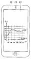
도 4는 도 1의 휴대용 온도 측정 전자장치를 이용하여, 체온 및 배경온도를 모니터링하는 화면을 도시한 예시 화면이다.
도 5는 본 발명의 다른 실시예에 따른 휴대용 온도 측정 전자장치를 이용하여, 체온을 모니터링하는 화면을 도시한 예시 화면이다.1 is a block diagram of a portable temperature measuring electronic device according to an embodiment of the present invention.
FIG. 2 is a perspective view of a storage case of the portable temperature measuring electronic device of FIG. 1.
3A and 3B are bottom views illustrating the rear surface of the storage case of FIG. 2.
4 is an exemplary screen illustrating a screen for monitoring a body temperature and a background temperature by using the portable temperature measuring electronic device of FIG. 1.
5 is an exemplary screen illustrating a screen for monitoring body temperature by using a portable temperature measuring electronic device according to another embodiment of the present invention.
이하, 첨부한 도면들을 참조하여, 본 발명의 바람직한 실시예들을 보다 상세하게 설명하도록 한다.Hereinafter, preferred embodiments of the present invention will be described in more detail with reference to the accompanying drawings.
도 1은 본 발명의 일 실시예에 따른 휴대용 온도 측정 전자장치의 블록도이다.1 is a block diagram of a portable temperature measuring electronic device according to an embodiment of the present invention.
도 1을 참조하면, 본 실시예에 따른 휴대용 온도 측정 전자장치(100)는 이동통신단말 부재(200) 및 상기 이동통신단말 부재(200)를 수납하는 수납 케이스(300)를 포함한다.Referring to FIG. 1, the portable temperature measuring
상기 이동통신단말 부재(200)는 표시부(217), 전원(215), 제어부(213) 및 신호 수신부(211)를 포함한다. 또한, 상기 이동통신단말 부재(200)는 카메라(219) 및 메모리부(미도시)를 더 포함할 수 있다.The mobile
상기 표시부(217)는 상기 전원(215)으로부터 전력을 공급받아 영상을 표시하는 액정표시패널(liquid crystal display; LCD)을 포함한다. 다만, 상기 표시부(217)는 LCD 에 한정되지 않으며, 유기발광다이오드(organic light emitting diode; OLED) 등 다양한 표시 장치를 포함할 수 있다. 이하, 상기 표시부(217)가 LCD인 경우를 예를 들어 설명하도록 한다.The
상기 표시부(217)는 표시 패널(미도시) 및 표시 패널 구동부(미도시)를 포함한다. 상기 표시 패널은 제1 기판, 상기 제1 기판에 대향하는 제2 기판 및 상기 제1 및 제2 기판들 사이에 배치되는 액정층을 포함할 수 있다. 또한, 상기 표시 패널은 복수의 화소들을 포함한다. 상기 화소는 복수의 서브화소들을 포함한다. 예를 들어, 상기 서브화소들은 적색 서브화소, 녹색 서브화소 및 청색 서브화소를 포함할 수 있다. 상기 표시 패널은 복수의 게이트 라인들, 복수의 데이터 라인들을 포함한다. 상기 서브화소들은 상기 게이트 라인 및 데이터 라인들에 전기적으로 연결된다. 상기 표시 패널 구동부는 상기 게이트 라인들 및 상기 데이터 라인들에 전기적 신호를 인가하여, 상기 서브화소들을 온/오프 시킨다. 상기 서브화소들이 온/오프됨에 따라, 상기 서브화소들에 대응되는 액정들의 배향이 제어되고, 그로 인해 백라이트 광이 상기 액정들에 의해 투과 및 반사됨에 따라, 상기 표시부(217)에 영상이 표시된다.The
상기 제어부(213)는 상기 전원(215), 상기 신호 수신부(211), 상기 표시 패널 구동부(미도시) 및 상기 카메라(219)에 전기적으로 연결된다. 상기 제어부(213)는 상기 메모리부(미도시)로부터 데이터를 입력받아 각종 연산을 수행하는 마이크로프로세서(microprocessor), 어플리케이션 프로세서(application processor) 등 어떠한 형태의 프로세서일 수 있다. 본 실시예에서, 상기 제어부(213)는 상기 전원(215)으로부터 전력을 공급받아, 상기 신호 수신부(211)로부터 수신되는 전기 신호를 수신하여 처리하고, 상기 처리된 결과에 기초하여 상기 표시 패널 구동부(미도시)를 제어하여, 상기 표시부(217)에 영상을 표시한다. 또한, 상기 제어부(213)는 상기 카메라(219)로부터 수신되는 영상 신호를 수신하여 처리하고, 그에 따라 상기 표시부(217)에 영상을 표시할 수 있다.The
상기 전원(215)은 상기 제어부(213)에 전기적으로 연결된다. 또한, 상기 전원(215)은 후술할, 상기 수납 케이스(300)의 전원 연결부(319)에 전기적으로 연결될 수 있다. 상기 전원(215)이 상기 전원 연결부(319)에 전기적으로 연결되는 경우, 상기 전원(215)으로부터 상기 수납 케이스(300)에 전력이 인가될 수 있다. 실시예에 따라, 상기 전원(215)은 상기 이동통신단말 부재(200)의 본체 내에 실장되거나, 또는 상기 본체에 대하여 탈부착되도록 연결될 수 있다.The
상기 메모리부(미도시)는 상기 카메라(219) 또는 상기 신호 수신부(211)를 통해 수신된 전기 신호들(데이터)을 저장한다. 상기 메모리부에 저장된 데이터는 상기 제어부(213)에 의하여 독출되거나 수정될 수 있다.The memory unit (not shown) stores electrical signals (data) received through the
상기 신호 수신부(211)는 후술할, 상기 수납 케이스(300)의 신호 송신부(317)로부터 전송되는 신호를 수신한다. 상기 신호 수신부(211)는 소정의 파장대를 갖는 전파를 수신하는 안테나를 포함한다. 상기 안테나는 상기 이동통신단말 부재(200)의 상기 본체 내부에 실장되거나, 또는 상기 본체의 외부로 돌출될 수 있다.The
상기 카메라(219)는 가시광 파장대의 가시 영상을 촬영한다. 상기 촬영된 가시 영상은 상기 메모리부(미도시)에 저장되고, 상기 제어부(213)에 의해 독출될 수 있다. 실시예에 따라, 상기 카메라(219)에 의해 촬영되는 상기 가시 영상은 실시간으로 상기 표시부(217)에 영상으로 표시될 수 있다.The
상기 수납 케이스(300)는 온도 센싱부(311), 상기 온도 센싱부(311)에 연결되는 AD 컨버터부(313), 신호 보정부(315) 및 신호 송신부(317)를 포함한다. 상기 수납 케이스(300)는 상기 이동통신단말 부재(200)의 상기 전원(215)에 전기적으로 연결되는 전원 연결부(319)를 더 포함할 수 있다.The
상기 온도 센싱부(311)는 적어도 일부가 외면에 노출되어 온도를 측정하며, 상기 측정된 온도에 기초하여 아날로그 신호를 출력한다. 상기 온도 센싱부(311)는 상기 아날로그 신호를 증폭시키는 신호 증폭부(312)를 포함할 수 있다.The
상기 온도 센싱부(311)는 상기 수납 케이스(300)의 용도에 따라, 접촉식 또는 비접촉식으로 상기 수납 케이스(300) 외부의 온도를 측정한다. 상기 온도 센싱부(311)가 접촉식으로 동작하는 경우, 상기 온도 센싱부(311)는, 상기 노출된 외면 상에 접촉되는 물체로부터 열을 전달받아, 상기 전달된 열에 의해 상기 물체의 온도를 측정하는 접촉 온도 센서를 포함한다. 이 경우, 상기 온도 센싱부(311)의 노출되는 외면은, 상기 수납 케이스(300)의 배면에 배치될 수 있다. 즉, 상기 온도 센싱부(311)의 일부가, 상기 이동통신단말 부재(200)를 수납하는 상기 수납 케이스(300)의 정면에 대향하는 배면에 노출됨으로써, 노출면(도 3a의 350) 상에 온도를 측정하고자 하는 물체가 용이하게 접촉할 수 있다. 그에 따라, 상기 접촉되는 물체로부터 열을 전달받고, 상기 전달된 열로부터 상기 물체의 표면 온도를 측정할 수 있다. 상기 휴대용 온도 측정 전자장치(100)가 사용자의 체온을 측정하는 용도로 사용되는 경우, 상기 노출면(350)은 상기 사용자의 신체 일부에 접촉될 수 있다.The
또한, 상기 온도 센싱부(311)가 접촉식으로 동작하는 경우, 상기 온도 센싱부(311)는 외부 온도를 측정하기 위한 배경온도 측정부(미도시)를 더 포함할 수 있다. 상기 배경온도 측정부는 상기 수납 케이스(300)의 배면에 노출되는 단부(도 3a의 340)를 통해 상기 수납 케이스(300) 외부의 배경온도를 측정할 수 있다.In addition, when the
한편, 상기 온도 센싱부(311)가 비접촉식으로 동작하는 경우, 상기 온도 센싱부(311)는 광 방출부(도 3b의 361) 및 광 감지부(도 3b의 363)를 포함할 수 있다. 또한, 상기 온도 센싱부(311)는 상기 수납 케이스(300) 외부의 온도를 측정하기 위한 배경 복사 감지부(미도시)를 더 포함할 수 있다.Meanwhile, when the
상기 광 방출부(361)는 표적 물체에 대하여 일정한 파장대의 광을 조사할 수 있다. 예를 들어, 상기 파장대는 적외선 영역을 포함할 수 있다. 즉, 상기 광 방출부(361)는 약 750 nm(나노미터) 이상 약 1 mm(밀리미터) 이하의 적외선을 조사할 수 있다.The light emitter 361 may irradiate a target wavelength with light of a target object. For example, the wavelength band may include an infrared region. That is, the light emitter 361 may irradiate infrared rays of about 750 nm (nanometer) or more and about 1 mm (millimeter) or less.
상기 광 감지부(363)는 상기 조사된 광이 상기 표적 물체에 반사되어 되돌아오는 광을 감지하며, 감지된 광량을 제1 전기 신호로 변환할 수 있다. 즉, 상기 광의 파장대가 적외선 영역을 포함하는 경우, 상기 광 방출부(361)에 의해 조사되어 되돌아오는 적외선은, 소정의 표면 온도를 갖는 상기 표적 물체로부터 방출되는 적외선과 합해지며, 그에 따라, 상기 감지된 적외선의 광량으로부터 상기 표적 물체의 표면 온도를 나타내는 제1 전기 신호가 얻어질 수 있다. 이때, 상기 표적 물체로부터 방출되는 적외선의 인텐시티(intensity)는 상기 표면 온도에 따라 달라질 수 있다. 상기 광 감지부(363)는 상기 되돌아오는 광을 집중시키도록 소정의 곡률을 갖는 렌즈부(미도시)를 더 포함할 수 있다.The
상기 광 감지부(363)는 상기 표적 물체로부터의 복사 에너지가 아닌, 배경 복사 에너지를 감지하며, 상기 감지된 배경 복사 에너지량을 제2 전기 신호로 변환하는 배경 복사 감지부를 더 포함할 수 있다. 이 경우, 상기 제2 전기 신호는 상기 표적 물체의 표면 온도가 아닌, 배경 온도를 모니터링하는 데에 사용될 수 있다.The
한편, 상기 온도 센싱부(311)가 비접촉식으로 동작하는 경우, 상기 온도 센싱부(311)는 적외선 파장대의 적외 영상을 촬영하는 적외선 카메라(미도시)를 포함할 수 있다. 이 경우, 상기 적외선 카메라는 상기 수납 케이스(300) 외부에서 인가되는 모든 적외선을 측정하여, 상기 적외선 카메라가 바라보는 영역의 적외 영상을 영상 신호로 출력할 수 있다.On the other hand, when the
상기 AD 컨버터부(313)는 상기 온도 센싱부(311)로부터 아날로그 신호가 출력되는 경우, 상기 아날로그 신호를 제1 디지털 신호로 변환한다.The
상기 신호 보정부(315)는 미리 설정된 온도 보정 알고리즘에 따라 상기 제1 디지털 신호를 보정하여, 보정된 온도를 나타내는 제2 디지털 신호를 출력한다. 상기 신호 보정부(315)는 상기 제1 디지털 신호에 대해 연산 처리하기 위한 각종 프로세서(processor)를 포함할 수 있다. 상기 온도 보정 알고리즘은, 상기 접촉 물체 또는 상기 표적 물체로부터 측정되는 온도를 적절한 온도 범위 내에서 보정하는, 어떠한 보정 알고리즘도 포함한다.The
상기 신호 송신부(317)는 상기 제2 디지털 신호를 소정의 대역폭을 갖는 신호 채널을 통해 무선 송신한다. 상기 신호 송신부(317)는 상기 접촉 물체 또는 상기 표적 물체로부터 측정된 온도를 나타내는 제1 전기 신호와, 상기 배경 온도를 나타내는 제2 전기 신호를, 상기 이동통신단말 부재(200)의 신호 수신부(211)에 대해 송신할 수 있다. 또는, 상기 신호 송신부(317)는 상기 적외선 카메라로부터 촬영되는 적외 영상을 나타내는 영상 신호를 상기 이동통신단말 부재(200)의 신호 수신부(211)에 대해 송신할 수 있다.The
도 2는 도 1의 휴대용 온도 측정 전자장치의 수납 케이스의 사시도이다.FIG. 2 is a perspective view of a storage case of the portable temperature measuring electronic device of FIG. 1.
도 2를 참조하면, 상기 수납 케이스(300)는 제1 면(321) 및 상기 제1 면으로부터 연장되는 제2 면(322)을 포함한다. 상기 제1 면(321)은 이동통신단말 부재(200)에 실장되는 카메라의 시야를 확보시키기 위한 노출공(330)을 포함할 수 있다. 상기 제2 면(322)은 상기 제1 면(321)에 대하여 수직하게 연장될 수 있다. 상기 제1 면(321)은 상기 이동통신단말 부재(200)의 배면의 적어도 일부를 커버한다. 상기 제2 면(322)은 상기 이동통신단말 부재(200)의 측면의 적어도 일부를 커버한다. 상기 제1 면(321) 및 상기 제2 면(322)은 상기 이동통신단말 부재(200)를 보호하기 위해 소정의 탄성도를 갖는 재질로 형성될 수 있다. 또는 상기 제1 면(321) 및 상기 제2 면(322)는 서로 다른 재질로 형성될 수 있다.Referring to FIG. 2, the
상기 수납 케이스(300)는 상기 이동통신단말 부재(200)의 전원(215)에 전기적으로 연결되는 전원 연결부(319)를 포함할 수 있다. 상기 전원 연결부(319)는 상기 제2 면(322)의 내측면에 배치될 수 있다.The
상기 수납 케이스(300)가 상기 전원 연결부(319)를 포함하는 경우, 상기 수납 케이스(300)는 온도 센싱부(311), AD 컨버터부(313), 신호 보정부(315) 및 신호 송신부(317) 중 적어도 하나를 상기 전원 연결부(319)에 전기적으로 연결하는 연결 배선(318)을 더 포함할 수 있다. 상기 연결 배선(318)은 상기 온도 센싱부(311), 상기 AD 컨버터부(313), 상기 신호 보정부(315) 및 상기 신호 송신부(317) 중 적어도 어느 하나가 배치되는 커버면(314)을 상기 전원 연결부(319)에 연결할 수 있다. 상기 연결 배선(318)은 한 개 또는 복수개가 상기 제1 면(321) 상에 배치될 수 있다. 또는, 상기 연결 배선(318)은 상기 제1 면(321) 상에 노출되지 않도록 상기 수납 케이스(300) 내부에 배치될 수 있다.When the
도 3a 및 도 3b는 도 2의 수납 케이스의 배면을 도시한 저면도들이다. 구체적으로, 도 3a는 상기 수납 케이스(300)의 온도 센싱부(311)가 접촉식으로 동작하는 경우, 도 3b는 상기 수납 케이스(300)의 온도 센싱부(311)가 비접촉식으로 동작하는 경우의 저면도들을 각각 나타낸다.3A and 3B are bottom views illustrating the rear surface of the storage case of FIG. 2. Specifically, FIG. 3A illustrates a case in which the
도 3a를 참조하면, 상기 온도 센싱부(311)가 접촉식으로 동작하는 경우, 상기 온도 센싱부(311)는 상기 수납 케이스(300)의 제1 면(321)에 반대되는 배면에서, 외부로 노출되는 노출면(350)을 포함할 수 있다. 상기 노출면(350)에 물체가 접촉하는 경우, 상기 물체로부터 열이 전달되며, 상기 전달된 열에 기초하여, 상기 물체의 표면 온도가 측정된다. 또한, 상기 온도 센싱부(311)가 배경온도 측정부를 더 포함하는 경우, 상기 배경온도 측정부의 단부(340)를 통해 상기 수납 케이스(300) 외부의 배경온도가 측정될 수 있다.Referring to FIG. 3A, when the
도 3b를 참조하면, 상기 온도 센싱부(311)가 비접촉식으로 동작하는 경우, 상기 온도 센싱부(311)는 광 방출부(361) 및 광 감지부(363)을 포함하고, 상기 광 방출부(361) 및 광 감지부(363)는 각각, 상기 수납 케이스(300)의 제1 면(321)에 반대되는 배면에, 일부 노출될 수 있다. 상기 광 감지부(363)는 상기 광 방출부(361)로부터 조사되어 표적 물체에 반사된 광이 잘 감지되도록, 상기 배면에 넓게 노출될 수 있다.Referring to FIG. 3B, when the
도 4는 도 1의 휴대용 온도 측정 전자장치를 이용하여, 체온 및 배경온도를 모니터링하는 화면을 도시한 예시 화면이다.4 is an exemplary screen illustrating a screen for monitoring a body temperature and a background temperature by using the portable temperature measuring electronic device of FIG. 1.
도 4를 참조하면, 이동통신단말 부재(200)의 표시부(217)에는, 수납 케이스(300)의 온도 센싱부(311)에 의해 측정되는 온도가, 시간에 따라 표시될 수 있다. 도 4에서는, 상기 온도 센싱부(311)가 접촉식으로 동작하는 경우, 노출면(350)에 접촉된 신체 온도 및 배경온도 측정부의 단부(340)를 통해 측정되는 배경온도의 시간에 따른 변화가 그래프로 표시되었다.Referring to FIG. 4, the temperature measured by the
도 5는 본 발명의 다른 실시예에 따른 휴대용 온도 측정 전자장치를 이용하여, 체온을 모니터링하는 화면을 도시한 예시 화면이다.5 is an exemplary screen illustrating a screen for monitoring body temperature by using a portable temperature measuring electronic device according to another embodiment of the present invention.
도 5를 참조하면, 이동통신단말 부재(200)의 표시부(217)에는, 이동통신단말 부재(200)의 가시 영상 카메라로부터 촬영되는 가시 영상 신호와, 수납 케이스(300)의 적외 영상 카메라로부터 촬영되는 적외 영상 신호가 합성된 영상이 표시될 수 있다. 상기 합성된 영상은 상기 적외 영상에 의해 감지되는 온도를 나타내기 위한 범례와 함께 표시될 수 있다.Referring to FIG. 5, the
이상에서 설명한 바와 같이, 본 발명의 실시예들에 따르면, 스마트 기기를 수납하는 케이스에 실장되는 온도 센서를 통해 원하는 신체 부위의 온도를 직접 측정함으로써, 스마트 기기의 사용자가 언제 어디서든 간편하게 체온을 모니터링할 수 있다.As described above, according to embodiments of the present invention, by directly measuring the temperature of the desired body part through a temperature sensor mounted on a case housing the smart device, the user of the smart device can easily monitor the body temperature anytime and anywhere can do.
또한, 스마트 기기에 온도계가 구비되지 않더라도, 스마트 기기에 연동되는 수납 케이스를 이용해 실시간으로 체온을 모니터링함으로써, 영유아 또는 환자들에게 발생되는 응급 상황에 대해 즉각적으로 대응할 수 있다.In addition, even if the smart device is not equipped with a thermometer, by monitoring the body temperature in real time using a storage case linked to the smart device, it is possible to respond immediately to an emergency situation occurring in infants or patients.
이상에서는 본 발명의 바람직한 실시예들을 참조하여 설명하였지만, 해당 기술분야의 숙련된 당업자 또는 해당 기술분야에 통상의 지식을 갖는 자라면 후술될 특허청구범위에 기재된 본 발명의 사상 및 기술 영역으로부터 벗어나지 않는 범위 내에서 본 발명을 다양하게 수정 및 변경시킬 수 있음을 이해할 수 있을 것이다.While the present invention has been described with reference to exemplary embodiments, it is to be understood that the invention is not limited to the disclosed exemplary embodiments, but, on the contrary, is intended to cover various modifications and equivalent arrangements included within the spirit and scope of the appended claims. It will be understood that various modifications and changes may be made thereto without departing from the scope of the present invention.
본 발명에 따른수납 케이스 및 이를 갖는 휴대용 온도 측정 전자장치는 스마트 기기를 사용하는 일반인, 환자, 노인, 보육인 등이, 건강 관리 또는 위급 상황 관리를 위하여, 자신 또는 타인의 체온을 측정하는 용도로 사용될 수 있는 산업상 이용 가능성을 갖는다.According to the invention The storage case and the portable temperature measuring electronic device having the same are an industry that can be used by a general person, a patient, an elderly person, a caregiver, etc., who use a smart device, to measure the body temperature of themselves or others for health care or emergency management. Phase availability.
100: 휴대용 온도 측정 전자장치200: 이동통신단말기
211: 신호 수신부213: 제어부
215: 전원부217: 표시부
219: 카메라300: 수납 케이스
311: 온도 센싱부312: 신호 증폭부
313: AD 컨버터부315: 신호 보정부
317: 신호 송신부319: 전원 연결부100: portable temperature measurement electronic device 200: mobile communication terminal
211: signal receiving unit 213: control unit
215: power supply unit 217: display unit
219: camera 300: storage case
311: temperature sensing unit 312: signal amplifier
313: AD converter unit 315: signal correction unit
317: signal transmitter 319: power connection
Claims (13)
Translated fromKorean상기 수납 부재는,
적어도 일부가 외면에 노출되어 온도를 측정하며, 상기 측정된 온도에 기초하여 아날로그 신호를 출력하는 온도 센싱부;
상기 아날로그 신호를 제1 디지털 신호로 변환하는 AD 컨버터부;
미리 설정된 온도 보정 알고리즘에 따라 상기 제1 디지털 신호를 보정하여, 보정된 온도를 나타내는 제2 디지털 신호를 출력하는 신호 보정부;
상기 제2 디지털 신호를 소정의 대역폭을 갖는 신호 채널을 통해 무선 송신하는 신호 송신부; 및
적외선 파장대의 적외 영상을 촬영하는 제1 카메라를 포함하고,
상기 이동통신단말 부재는,
표시부;
가시광 파장대의 가시 영상을 촬영하는 제2 카메라;
상기 수납 부재의 신호 송신부로부터 방출되는 신호를 수신하는 신호 수신부; 및
상기 수신된 신호를 처리하여 상기 표시부에 표시하는 제어부를 포함하고,
상기 수납 부재의 신호 송신부는 상기 제1 카메라로부터 촬영된 상기 적외 영상의 제1 영상 신호를 상기 이동통신단말 부재의 신호 수신부에 대하여 무선 송신하며,
상기 제2 카메라는 상기 가시 영상의 제2 영상 신호를 상기 제어부에 전송하고,
상기 이동통신단말부재의 제어부는 상기 제1 영상 신호 및 상기 제2 영상 신호를 이용하여, 합성된 제3 영상을 상기 표시부에 표시하는 휴대용 온도 측정 전자장치.A portable temperature measuring electronic device comprising a mobile communication terminal member and a housing member for accommodating the mobile communication terminal member.
Wherein:
A temperature sensing unit configured to measure at least a portion of the at least one portion exposed to the outer surface and output an analog signal based on the measured temperature;
An AD converter converting the analog signal into a first digital signal;
A signal correction unit correcting the first digital signal according to a preset temperature correction algorithm and outputting a second digital signal indicating the corrected temperature;
A signal transmitter for wirelessly transmitting the second digital signal through a signal channel having a predetermined bandwidth; And
It includes a first camera for taking an infrared image of the infrared wavelength band,
The mobile communication terminal member,
A display section;
A second camera which captures a visible image in the visible light wavelength band;
A signal receiver for receiving a signal emitted from the signal transmitter of the housing member; And
A control unit for processing the received signal and displaying the signal on the display unit;
The signal transmitter of the housing member wirelessly transmits a first video signal of the infrared image captured by the first camera to a signal receiver of the mobile communication terminal member,
The second camera transmits a second image signal of the visible image to the controller;
The controller of the mobile communication terminal member displays the synthesized third image on the display unit by using the first image signal and the second image signal.
상기 수납 부재는 상기 이동통신단말 부재의 전원부에 전기적으로 연결되는 전원 연결부를 더 포함하는 것을 특징으로 하는 휴대용 온도 측정 전자장치.12. The method of claim 11, wherein the mobile communication terminal member further comprises a power supply for supplying power to the control unit,
The accommodating member further comprises a power connection unit electrically connected to a power supply unit of the mobile communication terminal member.
Priority Applications (2)
| Application Number | Priority Date | Filing Date | Title |
|---|---|---|---|
| KR1020120134677AKR101384699B1 (en) | 2012-11-26 | 2012-11-26 | Receiving case and a mobile electronic device for measuring temperature having the same |
| PCT/KR2013/010609WO2014081212A1 (en) | 2012-11-26 | 2013-11-21 | Housing case and portable temperature measuring electronic device comprising same |
Applications Claiming Priority (1)
| Application Number | Priority Date | Filing Date | Title |
|---|---|---|---|
| KR1020120134677AKR101384699B1 (en) | 2012-11-26 | 2012-11-26 | Receiving case and a mobile electronic device for measuring temperature having the same |
Publications (1)
| Publication Number | Publication Date |
|---|---|
| KR101384699B1true KR101384699B1 (en) | 2014-04-14 |
Family
ID=50657521
Family Applications (1)
| Application Number | Title | Priority Date | Filing Date |
|---|---|---|---|
| KR1020120134677AExpired - Fee RelatedKR101384699B1 (en) | 2012-11-26 | 2012-11-26 | Receiving case and a mobile electronic device for measuring temperature having the same |
Country Status (2)
| Country | Link |
|---|---|
| KR (1) | KR101384699B1 (en) |
| WO (1) | WO2014081212A1 (en) |
Cited By (2)
| Publication number | Priority date | Publication date | Assignee | Title |
|---|---|---|---|---|
| EP2977732A3 (en)* | 2014-07-04 | 2016-04-06 | Arc Devices (NI) Limited | Thermometer having a digital infrared sensor |
| KR20220101935A (en)* | 2021-01-12 | 2022-07-19 | 주식회사 에이치티솔루션 | Smartphone cradle thermometers and haccp managing system including the smartphone cradle thermometers |
Families Citing this family (2)
| Publication number | Priority date | Publication date | Assignee | Title |
|---|---|---|---|---|
| CN113495597B (en)* | 2020-04-03 | 2024-12-03 | 维沃移动通信有限公司 | Electronic device, control method and control device thereof, and computer readable storage medium |
| CN111564022A (en)* | 2020-05-26 | 2020-08-21 | 姜培生 | Intelligent terminal for detecting panoramic display of multi-target temperature data images |
Citations (2)
| Publication number | Priority date | Publication date | Assignee | Title |
|---|---|---|---|---|
| KR20050043702A (en)* | 2003-11-06 | 2005-05-11 | 산요덴키가부시키가이샤 | Temperature measuring device and temperature measurement teansmission device |
| KR20060038122A (en)* | 2004-10-29 | 2006-05-03 | 에스케이 텔레콤주식회사 | Health care method and system using mobile terminal |
Family Cites Families (3)
| Publication number | Priority date | Publication date | Assignee | Title |
|---|---|---|---|---|
| JP2002027051A (en)* | 2000-07-11 | 2002-01-25 | Tokai Tsushin Kogyo Kk | Cell phone with thermometer |
| CA2536371A1 (en)* | 2003-08-26 | 2005-03-10 | Redshift Systems Corporation | Infrared camera system |
| KR20060056449A (en)* | 2004-11-19 | 2006-05-24 | 주식회사 팬택 | Mobile communication terminal with thermometer module |
- 2012
- 2012-11-26KRKR1020120134677Apatent/KR101384699B1/ennot_activeExpired - Fee Related
- 2013
- 2013-11-21WOPCT/KR2013/010609patent/WO2014081212A1/ennot_activeCeased
Patent Citations (2)
| Publication number | Priority date | Publication date | Assignee | Title |
|---|---|---|---|---|
| KR20050043702A (en)* | 2003-11-06 | 2005-05-11 | 산요덴키가부시키가이샤 | Temperature measuring device and temperature measurement teansmission device |
| KR20060038122A (en)* | 2004-10-29 | 2006-05-03 | 에스케이 텔레콤주식회사 | Health care method and system using mobile terminal |
Cited By (3)
| Publication number | Priority date | Publication date | Assignee | Title |
|---|---|---|---|---|
| EP2977732A3 (en)* | 2014-07-04 | 2016-04-06 | Arc Devices (NI) Limited | Thermometer having a digital infrared sensor |
| KR20220101935A (en)* | 2021-01-12 | 2022-07-19 | 주식회사 에이치티솔루션 | Smartphone cradle thermometers and haccp managing system including the smartphone cradle thermometers |
| KR102561598B1 (en) | 2021-01-12 | 2023-08-01 | 주식회사 에이치티솔루션 | Smartphone cradle thermometers and haccp managing system including the smartphone cradle thermometers |
Also Published As
| Publication number | Publication date |
|---|---|
| WO2014081212A1 (en) | 2014-05-30 |
Similar Documents
| Publication | Publication Date | Title |
|---|---|---|
| US10955880B2 (en) | Folding electronic devices with geared hinges | |
| US11627887B2 (en) | PPG sensor having light arrival angle control at detector | |
| KR102655878B1 (en) | Electronic Device which calculates Blood pressure value using Pulse Wave Velocity algorithm and the Method for calculating Blood Pressure value thereof | |
| US10874348B1 (en) | Force sensing for PPG heart-rate performance enhancement and contact detection | |
| KR101384699B1 (en) | Receiving case and a mobile electronic device for measuring temperature having the same | |
| KR102560800B1 (en) | Electronic device for recognizing fingerprint using display | |
| KR102399821B1 (en) | Pcb including connector and grounds with different potentials and electronic device having the same | |
| US9788792B2 (en) | System for screening skin condition for tissue damage | |
| KR20170087218A (en) | Display and electronic device including the same | |
| US20140197317A1 (en) | Infrared Sensors for Electronic Devices | |
| KR20180090616A (en) | Electronic device with body information detection function | |
| US11178342B2 (en) | Camera systems for bendable electronic devices | |
| US10335087B2 (en) | Biosignal processing apparatus and biosignal processing method | |
| US12182652B2 (en) | Electronic system with ring device | |
| KR20150036015A (en) | Apparatus for measuring blood characteristics for deployment on a host device having a digital sensor | |
| EP3662832B1 (en) | Device and method for guiding measurement of biological signal in wearable device | |
| US20230210392A1 (en) | Physiological Sensing Patch for Coupling a Device to a Body of a User | |
| KR102373457B1 (en) | Electronic device and method for controlling sensitivity of a sensor based on properties of window in electronic device | |
| US20140003463A1 (en) | Non-contact thermometer | |
| US9074940B2 (en) | Miniature light sensing assembly | |
| JP5274829B2 (en) | Non-invasive living body measurement device | |
| US20180348380A1 (en) | An Apparatus for Detecting Electromagnetic Radiation and Method and Computer Program for Controlling an Apparatus for Detecting Electromagnetic Radiation | |
| EP4023145A1 (en) | Apparatus and method for estimating bio-information | |
| KR20160064902A (en) | Devices and methods for noninvasive physiological analysis | |
| KR102782706B1 (en) | Electronic device capable of measuring blood pressure and measuring blood pressure method with the same |
Legal Events
| Date | Code | Title | Description |
|---|---|---|---|
| A201 | Request for examination | ||
| PA0109 | Patent application | St.27 status event code:A-0-1-A10-A12-nap-PA0109 | |
| PA0201 | Request for examination | St.27 status event code:A-1-2-D10-D11-exm-PA0201 | |
| PN2301 | Change of applicant | St.27 status event code:A-3-3-R10-R13-asn-PN2301 St.27 status event code:A-3-3-R10-R11-asn-PN2301 | |
| R18-X000 | Changes to party contact information recorded | St.27 status event code:A-3-3-R10-R18-oth-X000 | |
| D13-X000 | Search requested | St.27 status event code:A-1-2-D10-D13-srh-X000 | |
| D14-X000 | Search report completed | St.27 status event code:A-1-2-D10-D14-srh-X000 | |
| E902 | Notification of reason for refusal | ||
| PE0902 | Notice of grounds for rejection | St.27 status event code:A-1-2-D10-D21-exm-PE0902 | |
| E13-X000 | Pre-grant limitation requested | St.27 status event code:A-2-3-E10-E13-lim-X000 | |
| P11-X000 | Amendment of application requested | St.27 status event code:A-2-2-P10-P11-nap-X000 | |
| P13-X000 | Application amended | St.27 status event code:A-2-2-P10-P13-nap-X000 | |
| E701 | Decision to grant or registration of patent right | ||
| PE0701 | Decision of registration | St.27 status event code:A-1-2-D10-D22-exm-PE0701 | |
| GRNT | Written decision to grant | ||
| PR0701 | Registration of establishment | St.27 status event code:A-2-4-F10-F11-exm-PR0701 | |
| PR1002 | Payment of registration fee | St.27 status event code:A-2-2-U10-U11-oth-PR1002 Fee payment year number:1 | |
| PG1601 | Publication of registration | St.27 status event code:A-4-4-Q10-Q13-nap-PG1601 | |
| PN2301 | Change of applicant | St.27 status event code:A-5-5-R10-R13-asn-PN2301 St.27 status event code:A-5-5-R10-R11-asn-PN2301 | |
| FPAY | Annual fee payment | Payment date:20170328 Year of fee payment:4 | |
| PR1001 | Payment of annual fee | St.27 status event code:A-4-4-U10-U11-oth-PR1001 Fee payment year number:4 | |
| R18-X000 | Changes to party contact information recorded | St.27 status event code:A-5-5-R10-R18-oth-X000 | |
| FPAY | Annual fee payment | Payment date:20180409 Year of fee payment:5 | |
| PR1001 | Payment of annual fee | St.27 status event code:A-4-4-U10-U11-oth-PR1001 Fee payment year number:5 | |
| R18-X000 | Changes to party contact information recorded | St.27 status event code:A-5-5-R10-R18-oth-X000 | |
| FPAY | Annual fee payment | Payment date:20190313 Year of fee payment:6 | |
| PR1001 | Payment of annual fee | St.27 status event code:A-4-4-U10-U11-oth-PR1001 Fee payment year number:6 | |
| PR1001 | Payment of annual fee | St.27 status event code:A-4-4-U10-U11-oth-PR1001 Fee payment year number:7 | |
| PN2301 | Change of applicant | St.27 status event code:A-5-5-R10-R11-asn-PN2301 | |
| PN2301 | Change of applicant | St.27 status event code:A-5-5-R10-R14-asn-PN2301 | |
| R18-X000 | Changes to party contact information recorded | St.27 status event code:A-5-5-R10-R18-oth-X000 | |
| PR1001 | Payment of annual fee | St.27 status event code:A-4-4-U10-U11-oth-PR1001 Fee payment year number:8 | |
| PR1001 | Payment of annual fee | St.27 status event code:A-4-4-U10-U11-oth-PR1001 Fee payment year number:9 | |
| PC1903 | Unpaid annual fee | St.27 status event code:A-4-4-U10-U13-oth-PC1903 Not in force date:20230408 Payment event data comment text:Termination Category : DEFAULT_OF_REGISTRATION_FEE | |
| PC1903 | Unpaid annual fee | St.27 status event code:N-4-6-H10-H13-oth-PC1903 Ip right cessation event data comment text:Termination Category : DEFAULT_OF_REGISTRATION_FEE Not in force date:20230408 |