KR101384353B1 - Substrate processing apparatus - Google Patents
Substrate processing apparatusDownload PDFInfo
- Publication number
- KR101384353B1 KR101384353B1KR1020130018042AKR20130018042AKR101384353B1KR 101384353 B1KR101384353 B1KR 101384353B1KR 1020130018042 AKR1020130018042 AKR 1020130018042AKR 20130018042 AKR20130018042 AKR 20130018042AKR 101384353 B1KR101384353 B1KR 101384353B1
- Authority
- KR
- South Korea
- Prior art keywords
- substrate
- susceptor
- process chamber
- passage
- processing apparatus
- Prior art date
- Legal status (The legal status is an assumption and is not a legal conclusion. Google has not performed a legal analysis and makes no representation as to the accuracy of the status listed.)
- Active
Links
- 239000000758substrateSubstances0.000titleclaimsabstractdescription120
- 238000000034methodMethods0.000claimsdescription69
- 239000007789gasSubstances0.000claimsdescription37
- 239000011261inert gasSubstances0.000claimsdescription10
- 238000010926purgeMethods0.000claimsdescription5
- 238000005530etchingMethods0.000description23
- 239000000460chlorineSubstances0.000description4
- 238000002347injectionMethods0.000description4
- 239000007924injectionSubstances0.000description4
- 238000009826distributionMethods0.000description3
- ZAMOUSCENKQFHK-UHFFFAOYSA-NChlorine atomChemical compound[Cl]ZAMOUSCENKQFHK-UHFFFAOYSA-N0.000description2
- PXGOKWXKJXAPGV-UHFFFAOYSA-NFluorineChemical compoundFFPXGOKWXKJXAPGV-UHFFFAOYSA-N0.000description2
- 229910052801chlorineInorganic materials0.000description2
- 239000011737fluorineSubstances0.000description2
- 229910052731fluorineInorganic materials0.000description2
- 238000004519manufacturing processMethods0.000description2
- 239000000463materialSubstances0.000description2
- 239000010453quartzSubstances0.000description2
- VYPSYNLAJGMNEJ-UHFFFAOYSA-Nsilicon dioxideInorganic materialsO=[Si]=OVYPSYNLAJGMNEJ-UHFFFAOYSA-N0.000description2
- 229910000838Al alloyInorganic materials0.000description1
- IJGRMHOSHXDMSA-UHFFFAOYSA-NAtomic nitrogenChemical compoundN#NIJGRMHOSHXDMSA-UHFFFAOYSA-N0.000description1
- 229910000990Ni alloyInorganic materials0.000description1
- 229910001080W alloyInorganic materials0.000description1
- 239000000956alloySubstances0.000description1
- XAGFODPZIPBFFR-UHFFFAOYSA-NaluminiumChemical compound[Al]XAGFODPZIPBFFR-UHFFFAOYSA-N0.000description1
- 229910052782aluminiumInorganic materials0.000description1
- 239000006227byproductSubstances0.000description1
- 239000000919ceramicSubstances0.000description1
- 238000005260corrosionMethods0.000description1
- 230000007797corrosionEffects0.000description1
- 238000010586diagramMethods0.000description1
- 229910001873dinitrogenInorganic materials0.000description1
- 239000011521glassSubstances0.000description1
- 229910000856hastalloyInorganic materials0.000description1
- 238000012986modificationMethods0.000description1
- 230000004048modificationEffects0.000description1
- 238000007789sealingMethods0.000description1
- 239000004065semiconductorSubstances0.000description1
- 239000000126substanceSubstances0.000description1
- WFKWXMTUELFFGS-UHFFFAOYSA-NtungstenChemical compound[W]WFKWXMTUELFFGS-UHFFFAOYSA-N0.000description1
- 229910052721tungstenInorganic materials0.000description1
- 239000010937tungstenSubstances0.000description1
Images


Classifications
- F—MECHANICAL ENGINEERING; LIGHTING; HEATING; WEAPONS; BLASTING
- F16—ENGINEERING ELEMENTS AND UNITS; GENERAL MEASURES FOR PRODUCING AND MAINTAINING EFFECTIVE FUNCTIONING OF MACHINES OR INSTALLATIONS; THERMAL INSULATION IN GENERAL
- F16K—VALVES; TAPS; COCKS; ACTUATING-FLOATS; DEVICES FOR VENTING OR AERATING
- F16K51/00—Other details not peculiar to particular types of valves or cut-off apparatus
- F16K51/02—Other details not peculiar to particular types of valves or cut-off apparatus specially adapted for high-vacuum installations
- H—ELECTRICITY
- H01—ELECTRIC ELEMENTS
- H01L—SEMICONDUCTOR DEVICES NOT COVERED BY CLASS H10
- H01L21/00—Processes or apparatus adapted for the manufacture or treatment of semiconductor or solid state devices or of parts thereof
- H01L21/67—Apparatus specially adapted for handling semiconductor or electric solid state devices during manufacture or treatment thereof; Apparatus specially adapted for handling wafers during manufacture or treatment of semiconductor or electric solid state devices or components ; Apparatus not specifically provided for elsewhere
- H01L21/67005—Apparatus not specifically provided for elsewhere
- H01L21/67011—Apparatus for manufacture or treatment
- H01L21/67155—Apparatus for manufacturing or treating in a plurality of work-stations
- H01L21/6719—Apparatus for manufacturing or treating in a plurality of work-stations characterized by the construction of the processing chambers, e.g. modular processing chambers
- H—ELECTRICITY
- H01—ELECTRIC ELEMENTS
- H01L—SEMICONDUCTOR DEVICES NOT COVERED BY CLASS H10
- H01L21/00—Processes or apparatus adapted for the manufacture or treatment of semiconductor or solid state devices or of parts thereof
- H01L21/67—Apparatus specially adapted for handling semiconductor or electric solid state devices during manufacture or treatment thereof; Apparatus specially adapted for handling wafers during manufacture or treatment of semiconductor or electric solid state devices or components ; Apparatus not specifically provided for elsewhere
- H01L21/683—Apparatus specially adapted for handling semiconductor or electric solid state devices during manufacture or treatment thereof; Apparatus specially adapted for handling wafers during manufacture or treatment of semiconductor or electric solid state devices or components ; Apparatus not specifically provided for elsewhere for supporting or gripping
- H01L21/687—Apparatus specially adapted for handling semiconductor or electric solid state devices during manufacture or treatment thereof; Apparatus specially adapted for handling wafers during manufacture or treatment of semiconductor or electric solid state devices or components ; Apparatus not specifically provided for elsewhere for supporting or gripping using mechanical means, e.g. chucks, clamps or pinches
- H01L21/68714—Apparatus specially adapted for handling semiconductor or electric solid state devices during manufacture or treatment thereof; Apparatus specially adapted for handling wafers during manufacture or treatment of semiconductor or electric solid state devices or components ; Apparatus not specifically provided for elsewhere for supporting or gripping using mechanical means, e.g. chucks, clamps or pinches the wafers being placed on a susceptor, stage or support
- H01L21/68742—Apparatus specially adapted for handling semiconductor or electric solid state devices during manufacture or treatment thereof; Apparatus specially adapted for handling wafers during manufacture or treatment of semiconductor or electric solid state devices or components ; Apparatus not specifically provided for elsewhere for supporting or gripping using mechanical means, e.g. chucks, clamps or pinches the wafers being placed on a susceptor, stage or support characterised by a lifting arrangement, e.g. lift pins
Landscapes
- Engineering & Computer Science (AREA)
- Physics & Mathematics (AREA)
- Condensed Matter Physics & Semiconductors (AREA)
- General Physics & Mathematics (AREA)
- Manufacturing & Machinery (AREA)
- Computer Hardware Design (AREA)
- Microelectronics & Electronic Packaging (AREA)
- Power Engineering (AREA)
- General Engineering & Computer Science (AREA)
- Mechanical Engineering (AREA)
- Drying Of Semiconductors (AREA)
Abstract
Description
Translated fromKorean본 발명은 챔버 내에서 가스를 이용한 제조 공정이 이루어지는 기판 처리 장치에 관한 것이다.The present invention relates to a substrate processing apparatus in which a manufacturing process using gas is performed in a chamber.
일반적으로, 공정 챔버는 진공 상태에서 기판에 대한 처리 공정을 수행한다. 그리고, 로드락 챔버는 공정 챔버에 연결되는 부분으로 공정 챔버의 진공도를 유지시켜 주면서, 공정 챔버에서 처리될 기판을 그리고 공정 챔버에서 공정이 완료된 기판을 반입 및 반출하기 위한 기판을 임시적으로 보관하기 위한 공간이다.In general, the process chamber performs a processing process on the substrate in a vacuum state. The load lock chamber is a part connected to the process chamber while maintaining the vacuum degree of the process chamber, and temporarily storing the substrate to be processed and processed in the process chamber and the substrate for importing and unloading the substrate having been processed in the process chamber. Space.
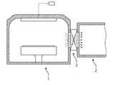
도 4는 종래의 기판 처리 장치의 개략적인 도면이다.4 is a schematic diagram of a conventional substrate processing apparatus.
도 4를 참조하면, 기판 처리 장치는 공정 챔버(1)와 로드락 챔버(2)를 포함하며, 로드락 챔버(2)와 공정 챔버(1) 사이에는 인접된 상태로 게이트 밸브(3)가 마련된다. 게이트 밸브(3)는 로드락 챔버(2)와 공정 챔버(1)의 사이에 개재되어 상호 연결되어 통하는 그들을 개방하고 폐쇄하는 기능을 한다.Referring to FIG. 4, the substrate processing apparatus includes a
이러한 기판 처리 장치에서는 게이트 밸브(3) 개방시 로드락 챔버(2)와 공정 챔버(1) 간의 기압차에 의한 역류 현상으로 공정 챔버(1)에 잔류하고 있는 공정가스가 로드락 챔버(2)로 유입되어 로드락 챔버(2) 내부를 부식시키는 문제가 발생될 수 있다.In such a substrate processing apparatus, a process gas remaining in the
본 발명의 실시예들은 공정 챔버 내의 공정가스가 로드락 챔버로 역류하는 것을 방지할 수 있는 기판 처리 장치를 제공하고자 한다.Embodiments of the present invention are directed to providing a substrate processing apparatus capable of preventing a process gas in a process chamber from flowing back into the load lock chamber.
본 발명의 목적은 여기에 제한되지 않으며, 언급되지 않은 또 다른 목적들은 아래의 기재로부터 당업자에게 명확하게 이해될 수 있을 것이다.The objects of the present invention are not limited thereto, and other objects not mentioned can be clearly understood by those skilled in the art from the following description.
본 발명의 일 측면에 따르면, 내부 공간에 기판 서셉터가 설치되는 공정 챔버; 상기 공정 챔버 일측에 설치되고, 상기 공정챔버의 내부공간으로 기판을 반입 및 반출하기 위한 통로를 제공하는 기판 출입부; 상기 기판 출입부를 개폐하는 게이트 밸브; 상기 공정 챔버의 내부공간에 설치되며, 상기 기판 출입부의 통로가 상기 공정 챔버의 내부공간과는 독립된 공간으로 구획되도록 상기 통로를 개폐하는 커버를 포함하는 기판 처리 장치가 제공될 수 있다.According to an aspect of the invention, the process chamber is a substrate susceptor is installed in the inner space; A substrate entrance part provided at one side of the process chamber and providing a passage for carrying in and out of the substrate into an interior space of the process chamber; A gate valve for opening and closing the substrate entrance and exit; A substrate processing apparatus may be provided in an interior space of the process chamber and include a cover that opens and closes the passage so that a passage of the substrate entrance and exit is divided into a space independent of the interior space of the process chamber.
또한, 상기 기판 처리 장치는 상기 기판 출입부의 통로에 불활성가스를 공급하기 위한 퍼지 공급부를 더 포함할 수 있다.In addition, the substrate processing apparatus may further include a purge supply unit for supplying an inert gas to the passage of the substrate entrance.
또한, 상기 기판 출입부는 상기 퍼지 공급부를 통해 공급되는 불활성가스를 상기 통로로 제공하는 가스공급홀을 포함할 수 있다.In addition, the substrate access portion may include a gas supply hole for providing an inert gas supplied through the purge supply to the passage.
또한, 상기 기판 서셉터를 업다운 시키기 위한 서셉터 구동부; 및 상기 기판 서셉터에 설치되고, 상기 내부 공간이 상기 기판 서셉터 상부의 공정 영역과 상기 기판 서셉터 하부의 배기 영역으로 구획되도록 상기 기판 서셉터와 상기 공정 챔버의 외벽 사이를 커버하는 링 플레이트를 포함할 수 있다.In addition, a susceptor driver for up and down the substrate susceptor; And a ring plate disposed in the substrate susceptor and covering the substrate susceptor and an outer wall of the process chamber so that the inner space is partitioned into a process region above the substrate susceptor and an exhaust region below the substrate susceptor. It may include.
또한, 상기 링 플레이트는 다수의 배기공들을 포함할 수 있다.In addition, the ring plate may include a plurality of exhaust holes.
또한, 상기 커버는 상기 링 플레이트의 가장자리로부터 수직한 방향으로 연장되어 형성되고, 상기 기판 서셉터의 업다운 동작과 연동하여 상기 통로를 개폐할 수 있다.The cover may extend in a vertical direction from an edge of the ring plate, and may open and close the passage in conjunction with an up-down operation of the substrate susceptor.
본 발명의 실시예들은 공정 챔버 내의 잔류 가스가 기판 출입부를 통해 로드락 챔버로 역류하는 것을 방지할 수 있다.Embodiments of the present invention can prevent residual gas in the process chamber from flowing back through the substrate entrance to the load lock chamber.
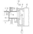
도 1은 본 발명의 일 실시예에 따른 기판 처리 장치의 단면도이다.
도 2는 커버에 의해 닫혀진 기판 출입부를 보여주는 도면이다.
도 3은 커버에 의해 개방된 기판 출입부를 보여주는 도면이다.1 is a cross-sectional view of a substrate processing apparatus according to an embodiment of the present invention.
2 shows a substrate entrance closed by a cover.
3 is a view showing a substrate entrance opened by a cover.
이하 첨부된 도면을 참조하여 본 발명의 바람직한 실시 예에 따른 기판 처리 장치를 상세히 설명한다.Hereinafter, a substrate processing apparatus according to a preferred embodiment of the present invention will be described in detail with reference to the accompanying drawings.
본 발명을 설명함에 있어, 관련된 공지 구성 또는 기능에 대한 구체적인 설명이 본 발명의 요지를 흐릴 수 있다고 판단되는 경우에는 그 상세한 설명은 생략한다.In the following description of the present invention, a detailed description of known functions and configurations incorporated herein will be omitted when it may make the subject matter of the present invention rather unclear.
도 1은 본 발명의 일 실시예에 따른 기판 처리 장치의 단면도이다. 도 2 및 도 3은 커버에 의해 개폐되는 기판 출입부를 보여주는 도면들이다.1 is a cross-sectional view of a substrate processing apparatus according to an embodiment of the present invention. 2 and 3 are views showing the substrate entrance and the opening and closing by the cover.
본 실시 예에서는 기판 표면을 식각 가스를 사용하여 기판의 표면을 식각하는 건식 기상 식각(gas phase etcher; GPE) 공정을 수행하기 위한 장치를 예로 들어 설명한다. 그러나 본 발명의 기술적 사상은 이에 한정되지 않으며, 공정 가스를 이용하여 기판 표면을 처리하는 장치에도 적용될 수 있다.In this embodiment, an apparatus for performing a gas phase etcher (GPE) process for etching a surface of a substrate using an etching gas is described as an example. However, the technical idea of the present invention is not limited thereto, and may be applied to an apparatus for treating a substrate surface using a process gas.
식각 공정의 대상인 기판은 어떠한 기판도 가능하며, LCD 패널용 유리기판, 태양전지소자용 기판, LED 웨이퍼, 반도체 웨이퍼, 아몰레드(Amoled) 기판 등이 그 대상이 될 수 있다.The substrate to be subjected to the etching process can be any substrate, and can be a glass substrate for an LCD panel, a substrate for a solar cell device, an LED wafer, a semiconductor wafer, or an amorphous substrate.
도 1을 참조하면, 본 발명의 기판 처리 장치(10)는 공정 챔버(100), 가스분사부(130), 기판 서셉터(140), 링 플레이트(150) 그리고 기판 출입부(180)를 포함한다.Referring to FIG. 1, the
공정 챔버(process chamber, 100)는 기판(S)에 대한 식각 공정을 수행할 수 있도록 밀폐된 내부 공간을 제공한다. 공정 챔버(100)는 상측이 개방된 챔버 몸체(110)와, 챔버 몸체(110)에 탈착 가능하게 결합되는 상부 돔(120)을 포함한다.A
챔버 몸체(110)는 상측이 개방된 형태로, 지면과 대체로 나란한 챔버 베이스(112)와, 챔버 베이스(112)로부터 대체로 수직하게 설치되는 측벽(114)을 포함한다. 챔버 몸체(110)의 측벽(114)에는 진공펌프와 연결되는 진공흡입포트(vacuum suction port, 116)가 제공된다.The
진공 배기부(190)는 공정 챔버(100)의 내부를 진공 상태로 형성하고, 식각 프로세스가 수행되는 동안 발생하는 반응 부산물 등을 배출시키기 위한 것으로, 진공 펌프(192)와, 진공흡입포트(116)에 연결되는 진공 라인(194)을 포함할 수 있다. 공정 챔버(100)와 진공 펌프(192)를 연결하는 진공 라인(194)에는 각종 밸브(도시되지 않음)가 설치되어 진공 라인(194)을 개폐하고 개폐 정도를 조절함으로써 진공 정도를 조절할 수 있다.The
기판 출입부(180)는 진공흡입포트(116)와 마주하는 챔버 몸체(110)의 측벽에 제공된다. 기판 출입부(180)는 공정 챔버(100)의 내부 공간으로 기판을 반입 및 반출하기 위한 통로(182)를 갖는다. 공정 챔버(100)는 기판 출입부(180)를 통해 로드락 챔버(20)와 연결되며, 기판 출입부(180)와 로드락 챔버(20) 사이에는 게이트 밸브(30)가 설치된다. 기판 출입부(180)의 통로에는 가스 공급홀(188)이 제공된다.The
기판 출입부(180)의 통로(182)에는 가스 공급홀(188)을 통해 불활성가스가 제공된다. 불활성가스는 퍼지 공급부(189)를 통해 공급된다. 기판 출입부(180)의 일단은 공정 챔버(100)의 내부공간과 연통되고, 타단은 게이트 밸브(30)와 연통된다. 기판 출입부(180)의 일단은 커버(156)에 의해 개폐된다.An inert gas is supplied to the
상부 돔(120)은 챔버 몸체(110)의 상측에 실링부재가 개재되어 결합되어 밀폐된 내부공간을 형성하기 위한 구성으로서, 하측이 개방된 돔 형태를 가질 수 있다.The
이때, 상부 돔(120)은 염소(Cl) 또는 불소(F)를 포함하는 식각가스가 주입되어 식각 공정이 이루어짐을 고려하여 내식성이 강한 석영 재질로 이루어질 수 있다. 그리고, 챔버 몸체(110)는 배기 포트(116)와 기판 출입부(180) 등이 설치되어야 하기 때문에 가공성이 떨어지는 석영으로는 제작이 어렵다. 따라서. 챔버 몸체(110)는 내화학성이 강하고 가공성과 용접성이 좋은 니켈 합금(hastelloy), 세라믹, 텅스텐, 텅스텐합금, 알루미늄, 알루미늄 합금 재질 중에서 이루어질 수 있다.In this case, the
가스 분사부(130)는 식각 공정을 수행할 수 있도록 기판 서셉터(140)와 마주하는 상부 돔(120)에 제공된다. 가스 분사부(130)는 가스공급장치(미도시)로부터 식각가스를 공급받아 처리공간으로 공급하기 위한 구성으로서, 공정 및 가스공급방식에 따라서 다양한 구성이 가능하다. 일 예로, 가스 분배부(130)는 균일한 가스 공급을 위해 동심원주에 일정 간격으로 형성되는 다수의 분사공(132)들을 갖는다. 가스 분배부(130)는 가장자리가 볼트와 같은 다수의 체결부재들에 의해 상부 돔(120)에 고정될 수 있다. 식각 가스는 가스 분배부(130)에 형성된 분사공(132)들을 통과하여 기판 서셉터(140) 상에 놓여진 놓여진 기판(S)으로 향한다.The
한편, 식각 공정에 사용되는 식각 가스는 식각 대상의 재질에 따라서 선택되며 다양한 가스가 사용될 수 있으며, 단일가스가 아닌 복수 종의 가스들이 혼합된 혼합가스들로 구성될 수 있다. 식각 가스의 일 예로서, 염소 또는 불소를 포함할 수 있다. 식각 가스는 다른 예로서, NF3, C2F6, CF4, CHF3, SF6, Cl2, BCl3, C2HF5 등이 있으며 상기 가스들 중 전부 또는 일부를 포함할 수 있다. 또한 식각 가스는 상기와 같은 가스 이외에 불활성가스, H2 및 O2 중 전부 또는 일부를 더 포함할 수 있다.Meanwhile, the etching gas used in the etching process may be selected according to the material of the etching target, and various gases may be used, and the mixed gases may be mixed with a plurality of gases instead of a single gas. As an example of the etching gas, chlorine or fluorine may be included. Another example of the etching gas may include
공정 챔버(100)의 처리공간에는 기판 출입부(180)의 개방에 따라 로봇에 의해 투입 위치되는 기판(S)이 놓여지는 기판 서셉터(140)가 구비된다.In the processing space of the
기판 서셉터(140)는 식각공정이 원활하게 수행될 수 있도록 기판(S)을 지지하기 위한 구성으로서, 설계조건 및 공정조건에 따라서 다양한 구성이 가능하다. 일 예로, 기판 서셉터(140)는 기판(S)을 고정하도록 구성되는 정전기척을 포함할 수 있다. 또한, 기판 서셉터(140)는 식각 공정중 기판(S)의 온도를 상승시키기 위한 히터를 포함할 수 있다.The
기판 서셉터(140)는 서셉터 구동부(148)에 의해 업다운된다. 기판 처리 공정은 기판 서셉터(140)가 업된 상태에서 이루어지고, 기판 반입 및 반출은 기판 서셉터(140)가 다운된 상태에서 이루어진다.The
기판 서셉터(140)에는 링 플레이트(150)가 설치된다. 링 플레이트(150)는 기판 서셉터(140)와 공정 챔버(100)의 외벽 사이를 커버할 수 있는 형태로 제공된다. 공정 챔버(100)의 내부 공간은 기판 서셉터(140) 및 링 플레이트(150)에 의해 기판 서셉터(140) 상부의 공정 영역(A)과 기판 서셉터(140) 하부의 배기 영역(B)으로 구획된다. 링 플레이트(150)는 공정 영역에서 배기 영역으로 가스 흐름이 이루어지도록 다수의 배기공(152)들을 갖는다.A
한편, 링 플레이트(150)는 커버(156)를 포함한다. 커버(156)는 링 플레이트(150)의 가장자리로부터 수직한 방향으로 연장되어 형성된다. 커버(156)는 기판 서셉터(140)의 업다운 동작과 연동하여 기판 출입부(180)의 통로(182)를 개폐한다. 즉, 커버(156)는 기판 출입부(180)의 통로(182)가 공정 챔버(100)의 내부 공간과는 독립된 공간으로 구획되도록 통로(182)를 개폐한다.On the other hand, the
상술한 구성을 갖는 기판 처리 장치에서의 식각 공정을 설명하면 다음과 같다.The etching process in the substrate processing apparatus having the above-described structure will be described below.
기판(S)은 기판 서셉터(140)가 다운 동작에 의해 하강된 상태에서 기판 출입부(180)의 통로(182)를 통해 공정 챔버(100)로 반입되어 기판 서셉터(140)에 놓여진다. 기판 로딩이 완료되면, 기판 서셉터(140)는 업 동작에 의해 상승되며, 이때 기판 출입부(180)의 통로(182)는 커버(156)에 의해 닫혀지게 된다(도 2참조). 즉, 기판 출입부(180)의 통로(182)는 커버(156)에 의해 공정 챔버(100)의 내부공간과는 독립된 공간으로 제공되며, 이 통로(182)에는 불활성가스( 일 예로, 질소가스)가 채워지게 된다. 식각 공정이 진행되는 동안 기판 출입부(180)의 통로(182)에는 불활성가스가 지속적으로 공급된다.The substrate S is loaded into the
도 3에서와 같이, 식각 공정이 완료된 후에는 기판 반출을 위해 게이트 밸브(30)가 개방되고 기판 서셉터(140)가 다운 동작에 의해 하강하게 된다. 이때, 기판 출입부(180)의 통로(182)에 갇혀 있던 불활성가스가 공정 챔버(100) 측으로 배기됨으로써 공정 챔버(100)의 내부공간에 잔류하고 있는 식각가스가 기판 출입부(180)를 통해 로드락 챔버(20)로 혼입되는 것을 방지할 수 있다.As shown in FIG. 3, after the etching process is completed, the
특히, 로드락 챔버(20)는 공정 챔버(100)의 압력보다 높게 유지하도록 하여 기판 반입 및 반출 동작시 잔류 식각 가스가 혼입되는 것을 방지한다.Particularly, the
이상의 설명은 본 발명의 기술 사상을 예시적으로 설명한 것에 불과한 것으로서, 본 발명이 속하는 기술 분야에서 통상의 지식을 가진 자라면 본 발명의 본질적인 특성에서 벗어나지 않는 범위에서 다양한 수정 및 변형이 가능할 것이다. 따라서, 본 발명에 개시된 실시 예들은 본 발명의 기술 사상을 한정하기 위한 것이 아니라 설명하기 위한 것이고, 이러한 실시 예에 의하여 본 발명의 기술 사상의 범위가 한정되는 것은 아니다. 본 발명의 보호 범위는 아래의 청구범위에 의하여 해석되어야 하며, 그와 동등한 범위 내에 있는 모든 기술 사상은 본 발명의 권리범위에 포함되는 것으로 해석되어야 할 것이다.The foregoing description is merely illustrative of the technical idea of the present invention, and various changes and modifications may be made by those skilled in the art without departing from the essential characteristics of the present invention. Therefore, the embodiments disclosed in the present invention are intended to illustrate rather than limit the scope of the present invention, and the scope of the technical idea of the present invention is not limited by these embodiments. The scope of protection of the present invention should be construed according to the following claims, and all technical ideas falling within the scope of the same shall be construed as falling within the scope of the present invention.
100 : 공정 챔버130 : 가스 분사부
140 : 기판 서셉터부150 : 링 플레이트
180 : 기판 출입부100: Process chamber 130:
140: substrate susceptor part 150: ring plate
180: Substrate entry /
Claims (5)
Translated fromKorean내부 공간에 기판 서셉터가 설치되는 공정 챔버;
상기 공정 챔버 일측에 설치되고, 상기 공정챔버의 내부공간으로 기판을 반입 및 반출하기 위한 통로를 제공하는 기판 출입부;
상기 기판 출입부를 개폐하는 게이트 밸브;
상기 공정 챔버의 내부공간에 설치되며, 상기 기판 출입부의 통로가 상기 공정 챔버의 내부공간과는 독립된 공간으로 구획되도록 상기 통로를 개폐하는 커버;
상기 기판 서셉터를 업다운 시키기 위한 서셉터 구동부; 및
상기 기판 서셉터에 설치되고, 상기 내부 공간이 상기 기판 서셉터 상부의 공정 영역과 상기 기판 서셉터 하부의 배기 영역으로 구획되도록 상기 기판 서셉터와 상기 공정 챔버의 외벽 사이를 커버하는 링 플레이트를 포함하는 기판 처리 장치.A substrate processing apparatus comprising:
A process chamber in which a substrate susceptor is installed in an inner space;
A substrate entrance part provided at one side of the process chamber and providing a passage for carrying in and out of the substrate into an interior space of the process chamber;
A gate valve for opening and closing the substrate entrance and exit;
A cover installed in an interior space of the process chamber and opening / closing the passage so that the passage of the substrate entrance and exit is divided into a space independent of the interior space of the process chamber;
A susceptor driver for up and down the substrate susceptor; And
A ring plate disposed on the substrate susceptor and covering the substrate susceptor and an outer wall of the process chamber such that the inner space is partitioned into a process region above the substrate susceptor and an exhaust region below the substrate susceptor; Substrate processing apparatus.
상기 기판 처리 장치는
상기 기판 출입부의 통로에 불활성가스를 공급하기 위한 퍼지 공급부를 더 포함하고,
상기 기판 출입부는
상기 퍼지 공급부를 통해 공급되는 불활성가스를 상기 통로로 제공하는 가스공급홀을 포함하는 것을 특징으로 하는 기판 처리 장치.The method of claim 1,
The substrate processing apparatus
Further comprising a purge supply section for supplying an inert gas to the passage of the substrate entrance section,
The substrate access portion
And a gas supply hole for providing an inert gas supplied through the purge supply part to the passage.
상기 링 플레이트는
다수의 배기공들을 포함하는 것을 특징으로 하는 기판 처리 장치.The method of claim 1,
The ring plate
Substrate processing apparatus comprising a plurality of exhaust holes.
상기 커버는
상기 링 플레이트의 가장자리로부터 수직한 방향으로 연장되어 형성되고, 상기 기판 서셉터의 업다운 동작과 연동하여 상기 통로를 개폐하는 것을 특징으로 하는 기판 처리 장치.
The method of claim 1,
The cover
And extending in a direction perpendicular to an edge of the ring plate and opening and closing the passage in conjunction with an up-down operation of the substrate susceptor.
Priority Applications (1)
| Application Number | Priority Date | Filing Date | Title |
|---|---|---|---|
| KR1020130018042AKR101384353B1 (en) | 2013-02-20 | 2013-02-20 | Substrate processing apparatus |
Applications Claiming Priority (1)
| Application Number | Priority Date | Filing Date | Title |
|---|---|---|---|
| KR1020130018042AKR101384353B1 (en) | 2013-02-20 | 2013-02-20 | Substrate processing apparatus |
Publications (1)
| Publication Number | Publication Date |
|---|---|
| KR101384353B1true KR101384353B1 (en) | 2014-04-14 |
Family
ID=50657423
Family Applications (1)
| Application Number | Title | Priority Date | Filing Date |
|---|---|---|---|
| KR1020130018042AActiveKR101384353B1 (en) | 2013-02-20 | 2013-02-20 | Substrate processing apparatus |
Country Status (1)
| Country | Link |
|---|---|
| KR (1) | KR101384353B1 (en) |
Cited By (1)
| Publication number | Priority date | Publication date | Assignee | Title |
|---|---|---|---|---|
| KR20240103266A (en)* | 2022-12-27 | 2024-07-04 | 주식회사 에스지에스코리아 | Device and method for removing particle of wafer deposition equipment |
Citations (2)
| Publication number | Priority date | Publication date | Assignee | Title |
|---|---|---|---|---|
| JP2000357678A (en)* | 1999-06-17 | 2000-12-26 | Nec Corp | Semiconductor manufacture apparatus |
| WO2011143062A2 (en)* | 2010-05-12 | 2011-11-17 | Applied Materials, Inc. | Confined process volume pecvd chamber |
- 2013
- 2013-02-20KRKR1020130018042Apatent/KR101384353B1/enactiveActive
Patent Citations (2)
| Publication number | Priority date | Publication date | Assignee | Title |
|---|---|---|---|---|
| JP2000357678A (en)* | 1999-06-17 | 2000-12-26 | Nec Corp | Semiconductor manufacture apparatus |
| WO2011143062A2 (en)* | 2010-05-12 | 2011-11-17 | Applied Materials, Inc. | Confined process volume pecvd chamber |
Cited By (2)
| Publication number | Priority date | Publication date | Assignee | Title |
|---|---|---|---|---|
| KR20240103266A (en)* | 2022-12-27 | 2024-07-04 | 주식회사 에스지에스코리아 | Device and method for removing particle of wafer deposition equipment |
| KR102777166B1 (en) | 2022-12-27 | 2025-03-07 | 주식회사 에스지에스코리아 | Device and method for removing particle of wafer deposition equipment |
Similar Documents
| Publication | Publication Date | Title |
|---|---|---|
| JP6039102B2 (en) | Dry vapor etching equipment | |
| US10056264B2 (en) | Atomic layer etching of GaN and other III-V materials | |
| US20170221720A1 (en) | Apparatus and method for treating substrates | |
| JP6495301B2 (en) | Thin film encapsulation processing system and processing kit enabling low-pressure tool replacement | |
| CN106505013B (en) | Substrate processing apparatus and manufacturing method of semiconductor device | |
| TWI404157B (en) | Mounting method of the mounting apparatus, a discharge prevention method between the processing apparatus and the power supply line of the stage apparatus | |
| US20160027673A1 (en) | Processing systems and methods for halide scavenging | |
| KR101536654B1 (en) | Method and apparatus for forming silicon film | |
| TWI407494B (en) | Apparatus for semiconductor processing | |
| TWI503439B (en) | Silicon film formation apparatus and method for using same | |
| KR101624605B1 (en) | Substrate processing apparatus and method of manufacturing semiconductor device | |
| US20130239889A1 (en) | Valve purge assembly for semiconductor manufacturing tools | |
| TWI658164B (en) | Thin film encapsulation processing system and process kit | |
| KR102828235B1 (en) | Process chamber process kit with protective coating | |
| CN110600356A (en) | Plasma apparatus, semiconductor manufacturing method, and gas delivery source | |
| KR102862873B1 (en) | Shadow ring lift to improve wafer edge performance | |
| US20150176128A1 (en) | Substrate Processing Apparatus | |
| KR101384353B1 (en) | Substrate processing apparatus | |
| JP2006253733A (en) | Plasma processing apparatus and method of cleaning the same | |
| JP2009253161A (en) | Plasma processing container and plasma processor | |
| US20150284847A1 (en) | Method of Forming an Epitaxial Layer and Apparatus for Processing a Substrate Used for the Method | |
| KR20230169742A (en) | Substate processing apparatus | |
| KR101573526B1 (en) | Furnace of MOCVD apparatus | |
| KR20150116003A (en) | Apparatus, system, and metho for treating substrate | |
| KR20250100902A (en) | Substrate treating apparatus and substrate treating method |
Legal Events
| Date | Code | Title | Description |
|---|---|---|---|
| A201 | Request for examination | ||
| PA0109 | Patent application | Patent event code:PA01091R01D Comment text:Patent Application Patent event date:20130220 | |
| PA0201 | Request for examination | ||
| E902 | Notification of reason for refusal | ||
| PE0902 | Notice of grounds for rejection | Comment text:Notification of reason for refusal Patent event date:20131221 Patent event code:PE09021S01D | |
| E701 | Decision to grant or registration of patent right | ||
| PE0701 | Decision of registration | Patent event code:PE07011S01D Comment text:Decision to Grant Registration Patent event date:20140330 | |
| GRNT | Written decision to grant | ||
| PR0701 | Registration of establishment | Comment text:Registration of Establishment Patent event date:20140404 Patent event code:PR07011E01D | |
| PR1002 | Payment of registration fee | Payment date:20140407 End annual number:3 Start annual number:1 | |
| PG1601 | Publication of registration | ||
| FPAY | Annual fee payment | Payment date:20170404 Year of fee payment:4 | |
| PR1001 | Payment of annual fee | Payment date:20170404 Start annual number:4 End annual number:4 | |
| FPAY | Annual fee payment | Payment date:20180326 Year of fee payment:5 | |
| PR1001 | Payment of annual fee | Payment date:20180326 Start annual number:5 End annual number:5 | |
| FPAY | Annual fee payment | Payment date:20190404 Year of fee payment:6 | |
| PR1001 | Payment of annual fee | Payment date:20190404 Start annual number:6 End annual number:6 | |
| FPAY | Annual fee payment | Payment date:20200313 Year of fee payment:7 | |
| PR1001 | Payment of annual fee | Payment date:20200313 Start annual number:7 End annual number:7 | |
| PR1001 | Payment of annual fee | Payment date:20210330 Start annual number:8 End annual number:8 | |
| PR1001 | Payment of annual fee | Payment date:20220317 Start annual number:9 End annual number:9 | |
| PR1001 | Payment of annual fee | Payment date:20230330 Start annual number:10 End annual number:10 |