KR101383357B1 - Light emitting device package and method of making the same - Google Patents
Light emitting device package and method of making the sameDownload PDFInfo
- Publication number
- KR101383357B1 KR101383357B1KR1020070086114AKR20070086114AKR101383357B1KR 101383357 B1KR101383357 B1KR 101383357B1KR 1020070086114 AKR1020070086114 AKR 1020070086114AKR 20070086114 AKR20070086114 AKR 20070086114AKR 101383357 B1KR101383357 B1KR 101383357B1
- Authority
- KR
- South Korea
- Prior art keywords
- light emitting
- emitting device
- light
- filler
- package
- Prior art date
- Legal status (The legal status is an assumption and is not a legal conclusion. Google has not performed a legal analysis and makes no representation as to the accuracy of the status listed.)
- Expired - Fee Related
Links
Images


Classifications
- H—ELECTRICITY
- H10—SEMICONDUCTOR DEVICES; ELECTRIC SOLID-STATE DEVICES NOT OTHERWISE PROVIDED FOR
- H10H—INORGANIC LIGHT-EMITTING SEMICONDUCTOR DEVICES HAVING POTENTIAL BARRIERS
- H10H20/00—Individual inorganic light-emitting semiconductor devices having potential barriers, e.g. light-emitting diodes [LED]
- H10H20/80—Constructional details
- H10H20/85—Packages
- H10H20/851—Wavelength conversion means
- H10H20/8516—Wavelength conversion means having a non-uniform spatial arrangement or non-uniform concentration, e.g. patterned wavelength conversion layer or wavelength conversion layer with a concentration gradient
- H—ELECTRICITY
- H10—SEMICONDUCTOR DEVICES; ELECTRIC SOLID-STATE DEVICES NOT OTHERWISE PROVIDED FOR
- H10H—INORGANIC LIGHT-EMITTING SEMICONDUCTOR DEVICES HAVING POTENTIAL BARRIERS
- H10H20/00—Individual inorganic light-emitting semiconductor devices having potential barriers, e.g. light-emitting diodes [LED]
- H10H20/80—Constructional details
- H10H20/85—Packages
- H10H20/852—Encapsulations
- H10H20/853—Encapsulations characterised by their shape
- H—ELECTRICITY
- H01—ELECTRIC ELEMENTS
- H01L—SEMICONDUCTOR DEVICES NOT COVERED BY CLASS H10
- H01L2924/00—Indexing scheme for arrangements or methods for connecting or disconnecting semiconductor or solid-state bodies as covered by H01L24/00
- H01L2924/0001—Technical content checked by a classifier
- H01L2924/0002—Not covered by any one of groups H01L24/00, H01L24/00 and H01L2224/00
- H—ELECTRICITY
- H10—SEMICONDUCTOR DEVICES; ELECTRIC SOLID-STATE DEVICES NOT OTHERWISE PROVIDED FOR
- H10H—INORGANIC LIGHT-EMITTING SEMICONDUCTOR DEVICES HAVING POTENTIAL BARRIERS
- H10H20/00—Individual inorganic light-emitting semiconductor devices having potential barriers, e.g. light-emitting diodes [LED]
- H10H20/80—Constructional details
- H10H20/882—Scattering means
Landscapes
- Led Device Packages (AREA)
Abstract
Translated fromKoreanDescription
Translated fromKorean본 발명은 발광 소자 패키지 및 그 제조방법에 관한 것으로 특히, 광 추출 효율을 향상시킬 수 있는 발광 소자 패키지 및 그 제조방법에 관한 것이다.The present invention relates to a light emitting device package and a method for manufacturing the same, and more particularly, to a light emitting device package and a method for manufacturing the same that can improve light extraction efficiency.
발광 다이오드(Light Emitting Diode: LED)는 전류를 빛으로 변환시키는 잘 알려진 반도체 발광 소자로서, 1962년 GaAsP 화합물 반도체를 이용한 적색 LED가 상품화 된 것을 시작으로 GaP:N 계열의 녹색 LED와 함께 정보 통신기기를 비롯한 전자장치의 표시 화상용 광원으로 이용되어 왔다.Light emitting diodes (LEDs) are well-known semiconductor light emitting devices that convert current into light. In 1962, red LEDs using GaAsP compound semiconductors were commercialized. GaP: N series green LEDs and information communication devices As a light source for a display image of an electronic device.
이러한 LED에 의해 방출되는 광의 파장은 LED를 제조하는데 사용되는 반도체 재료에 따른다. 이는 방출된 광의 파장이 가전자대(valence band) 전자들과 전도대(conduction band) 전자들 사이의 에너지 차를 나타내는 반도체 재료의 밴드갭(band-gap)에 따르기 때문이다.The wavelength of the light emitted by these LEDs depends on the semiconductor material used to fabricate the LED. This is because the wavelength of the emitted light depends on the band gap of the semiconductor material, which represents the energy difference between the valence band electrons and the conduction band electrons.
질화 갈륨 화합물 반도체(Gallium Nitride: GaN)는 높은 열적 안정성과 폭넓은 밴드갭(0.8 ~ 6.2eV)을 가지고 있어, LED를 포함한 고출력 전자부품 소자 개발 분야에서 많은 주목을 받아왔다.Gallium nitride semiconductors (GaN) have high thermal stability and wide bandgap (0.8 to 6.2 eV), and have attracted much attention in the field of high output electronic component development including LEDs.
이에 대한 이유 중 하나는 GaN이 타 원소들(인듐(In), 알루미늄(Al) 등)과 조합되어 녹색, 청색 및 백색광을 방출하는 반도체 층들을 제조할 수 있기 때문이다.One reason for this is that GaN can be combined with other elements (indium (In), aluminum (Al), etc.) to produce semiconductor layers that emit green, blue and white light.
이와 같이 방출 파장을 조절할 수 있기 때문에 특정 장치 특성에 맞추어 재료의 특징들에 맞출 수 있다. 예를 들어, GaN를 이용하여 광기록에 유익한 청색 LED와 백열등을 대치할 수 있는 백색 LED를 만들 수 있다.Since the emission wavelength can be controlled in this manner, it can be tailored to the characteristics of the material according to the specific device characteristics. For example, GaN can be used to create a white LED that can replace the blue LEDs and incandescent lamps that are beneficial for optical recording.
이러한 GaN 계열 물질의 이점들로 인해, GaN 계열의 LED 시장이 급속히 성장하고 있다. 따라서, 1994년에 상업적으로 도입한 이래로 GaN 계열의 광전자장치 기술도 급격히 발달하였다.Due to the advantages of these GaN-based materials, the GaN-based LED market is growing rapidly. Therefore, since commercial introduction in 1994, GaN-based optoelectronic device technology has rapidly developed.
상술한 바와 같은 GaN 계열 물질을 이용한 LED의 휘도 또는 출력은 크게, 활성층의 구조, 빛을 외부로 추출할 수 있는 광추출 효율, LED 칩의 크기, 램프 패키지 조립 시 몰드(mold)의 종류 및 각도, 형광물질 등에 의해서 좌우된다.The brightness or output of the LED using the GaN-based material as described above is large, the structure of the active layer, the light extraction efficiency to extract light to the outside, the size of the LED chip, the type and angle of the mold (mold) when assembling the lamp package , Fluorescent material and the like.
한편, 이러한 GaN 계열 반도체 성장이 다른 Ⅲ-Ⅴ족 화합물 반도체보다 어려운 이유 중에 하나는 고품질의 기판, 즉, GaN, InN, AlN 등의 물질의 웨이퍼가 존재하지 않기 때문이다.On the other hand, one of the reasons why the growth of GaN-based semiconductors is more difficult than other III-V compound semiconductors is that there are no high-quality substrates, that is, wafers made of materials such as GaN, InN, and AlN.
따라서 사파이어와 같은 이종 기판 위에 LED 구조를 성장하게 되며, 이때 많은 결함이 발생하게 되고, 이러한 결함들은 LED 성능에 큰 영향을 미치게 된다.Therefore, the LED structure is grown on a heterogeneous substrate such as sapphire, and many defects are generated, and these defects have a great influence on the LED performance.
최근 이와 같은 LED는 점점 휘도가 증가함으로써 디스플레이용 광원, 조명/자동차 광원으로 사용되어 지고 있다. 형광 물질을 이용하거나 색을 조합함으로 효율이 좋은 백색 광선도 구현이 가능하다. 이러한 목적으로 발광소자를 응용하기 위 해서는 소자의 동작 전압이 낮아야 하고 발광효율과 휘도가 높아야 한다.Recently, such LEDs are increasingly used as display light sources, lighting / automotive light sources. Efficient white light can be realized by using fluorescent materials or combining colors. In order to apply the light emitting device for this purpose, the operating voltage of the device should be low, and the luminous efficiency and brightness should be high.
이와 같은 LED 칩은 세라믹 등으로 제작되는 패키지에 장착되어 전극이 리드에 본딩되고, 그 위에 충진재를 충진하여 패키지를 제작하여 사용된다.Such an LED chip is mounted on a package made of ceramic or the like, and an electrode is bonded to a lead, and a filler is filled thereon to produce a package.
이때, 백색 LED를 구현하기 위해서는 적색, 녹색, 및 청색 LED 칩을 이용하거나, LED 칩 상에 별도의 형광체층을 형성하거나, 충진재에 형광체 혼합하여, LED 칩에서 발광하는 광과 형광체층에 의하여 색변환된 광이 혼합되어 백색 광을 발광할 수 있다.In this case, in order to implement a white LED, a red, green, and blue LED chip is used, or a separate phosphor layer is formed on the LED chip, or the phosphor is mixed with a filler, and the color is emitted by the light and the phosphor layer emitting from the LED chip. The converted light may be mixed to emit white light.
본 발명이 이루고자 하는 기술적 과제는, 광 출사면에 주기를 가지는 패턴을 형성하여 패키지는 박형을 유지하면서 광 추출 효율을 극대화할 수 있는 수직형 발광 소자의 제조방법을 제공하는 데 있다.An object of the present invention is to provide a method of manufacturing a vertical light emitting device that can form a pattern having a period on the light exit surface to maximize the light extraction efficiency while maintaining a thin package.
상기 기술적 과제를 이루기 위한 제1관점으로서, 본 발명은, 발광 소자 장착을 위한 장착부를 포함한 패키지 바디와; 상기 패키지 바디의 장착부에 장착되는 발광 소자와; 상기 발광 소자 상의 장착부에 채워지며, 외측면에 광 추출 패턴이 형성된 충진재를 포함하여 구성되는 것을 특징으로 한다.As a first aspect for achieving the above technical problem, the present invention, the package body including a mounting portion for mounting the light emitting device; A light emitting element mounted on a mounting portion of the package body; Filled in the mounting portion on the light emitting device, it characterized in that it comprises a filler formed with a light extraction pattern on the outer surface.
상기 기술적 과제를 이루기 위한 제2관점으로서, 본 발명은, 발광 소자 장착을 위한 장착부를 포함한 패키지 바디와; 상기 패키지 바디의 장착부에 장착되는 발광 소자와; 상기 발광 소자 상의 장착부에 채워지는 충진재와; 상기 충진재 상에 위치하며 광 추출 패턴을 가지는 광추출층을 포함하여 구성되는 것을 특징으로 한다.As a second aspect for achieving the above technical problem, the present invention, the package body including a mounting portion for mounting the light emitting device; A light emitting element mounted on a mounting portion of the package body; A filler filled in a mounting portion on the light emitting element; Located on the filler and characterized in that it comprises a light extraction layer having a light extraction pattern.
상기 기술적 과제를 이루기 위한 제3관점으로서, 본 발명은, 발광 소자 패키지의 제조방법에 있어서, 기판 상에 장착부와, 단위 패키지를 구분하는 관통홀을 형성하는 단계와; 상기 장착부에 발광 소자를 장착하는 단계와; 상기 발광 소자 상에 충진재를 충진하는 단계와; 상기 충진재 상에 광 추출 패턴을 형성하는 단계를 포함하여 구성되는 것을 특징으로 한다.As a third aspect of the present invention, there is provided a method of manufacturing a light emitting device package, the method comprising: forming a through hole for separating a mounting portion and a unit package on a substrate; Mounting a light emitting element on the mounting portion; Filling a filler on the light emitting device; It characterized in that it comprises a step of forming a light extraction pattern on the filler.
본 발명은 발광 소자 패키지의 충진재 상에 광 추출 패턴을 형성함으로써 발광 소자의 광 추출 효율을 최대화할 수 있다. 특히 웨이퍼 레벨 패키지에 적용했을 경우, 웨이퍼 레벨에서 충진재의 패터닝이 가능하여 한 번의 공정으로 패턴을 형성할 수 있다.The present invention can maximize the light extraction efficiency of the light emitting device by forming a light extraction pattern on the filler of the light emitting device package. In particular, when applied to a wafer level package, the filling material can be patterned at the wafer level, thereby forming a pattern in one step.
이하, 첨부된 도면을 참고하여 본 발명에 의한 실시예를 상세히 설명하면 다음과 같다.Hereinafter, embodiments of the present invention will be described in detail with reference to the accompanying drawings.
본 발명이 여러 가지 수정 및 변형을 허용하면서도, 그 특정 실시예들이 도면들로 예시되어 나타내어지며, 이하에서 상세히 설명될 것이다. 그러나 본 발명을 개시된 특별한 형태로 한정하려는 의도는 아니며, 오히려 본 발명은 청구항들에 의해 정의된 본 발명의 사상과 합치되는 모든 수정, 균등 및 대용을 포함한다.While the invention is susceptible to various modifications and alternative forms, specific embodiments thereof are shown by way of example in the drawings and will herein be described in detail. Rather, the intention is not to limit the invention to the particular forms disclosed, but rather, the invention includes all modifications, equivalents and substitutions that are consistent with the spirit of the invention as defined by the claims.
층, 영역 또는 기판과 같은 요소가 다른 구성요소 "상(on)"에 존재하는 것으로 언급될 때, 이것은 직접적으로 다른 요소 상에 존재하거나 또는 그 사이에 중간 요소가 존재할 수도 있다는 것을 이해할 수 있을 것이다. 표면과 같은 구성 요소의 일부가 '내부(inner)'라고 표현된다면 이것은 그 요소의 다른 부분들 보다도 소자의 외측으로부터 더 멀리 있다는 것을 의미한다고 이해할 수 있을 것이다.It will be appreciated that when an element such as a layer, region or substrate is referred to as being present on another element "on," it may be directly on the other element or there may be an intermediate element in between . If a part of a component, such as a surface, is expressed as 'inner', it will be understood that this means that it is farther from the outside of the device than other parts of the element.
이러한 용어들은 도면들에서 묘사된 방향에 더하여 소자의 다른 방향들을 포함하려는 의도라는 것을 이해할 수 있을 것이다. 마지막으로 '직접(directly)'라는 용어는 중간에 개입되는 어떠한 요소가 없다는 것을 의미한다. 여기에서 사용되는 바와 같이 '및/또는'이라는 용어는 기록된 관련 항목 중의 하나 또는 그 이상의 어느 조합 및 모든 조합을 포함한다.It will be understood that these terms are intended to include other directions of the device in addition to the direction depicted in the figures. Finally, the term 'directly' means that there is no element in between. As used herein, the term 'and / or' includes any and all combinations of one or more of the recorded related items.
비록 제1, 제2 등의 용어가 여러 가지 요소들, 성분들, 영역들, 층들 및/또는 지역들을 설명하기 위해 사용될 수 있지만, 이러한 요소들, 성분들, 영역들, 층들 및/또는 지역들은 이러한 용어에 의해 한정되어서는 안 된다는 것을 이해할 것이다.Although the terms first, second, etc. may be used to describe various elements, components, regions, layers and / or regions, such elements, components, regions, layers and / And should not be limited by these terms.
이러한 용어들은 단지 다른 영역, 층 또는 지역으로부터 어느 하나의 요소, 성분, 영역, 층 또는 지역들을 구분하기 위해 사용되는 것이다. 따라서 아래에서 논의된 제1 영역, 층 또는 지역은 제2 영역, 층 또는 지역이라는 명칭으로 될 수 있다.These terms are only used to distinguish one element, component, region, layer or region from another region, layer or region. Thus, the first region, layer or region discussed below may be referred to as a second region, layer or region.
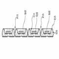
도 1에서 도시하는 바와 같이, 기판(10) 상에 발광 소자가 장착될 홈 형상의 장착부(11)와, 단위 패키지 분리 영역에 단위 패키지를 구분하는 관통홀(12)을 형성한다.As shown in FIG. 1, a groove-
기판(10)은 세라믹을 이용하거나 실리콘 웨이퍼와 같은 반도체를 이용할 수 있다. 이러한 기판(10)에 형성되는 장착부(11)와 관통홀(12)은 마스크(도시되지 않음)를 이용하여 건식 식각 또는 습식 식각을 이용하여 형성할 수 있다.The
이러한 장착부(11)는 발광 소자의 반사컵 역할을 할 수 있으며, 발광 소자에서 발광되는 빛이 효과적으로 추출되도록 깊이와 각도를 가질 수 있다.The
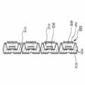
이후, 도 2에서와 같이, 이 장착부(11)와 기판(10)의 외측면을 연결하는 한 쌍의 전극(13)을 형성한다. 이러한 전극(13)은 관통홀(12)을 통하여 기판(10)의 전 면과 후면을 연결하여 형성될 수 있다.Thereafter, as shown in FIG. 2, a pair of
이와 같이 전극(13)이 기판(10)의 후면에 연결되어 형성되면 PCB와 같은 보드에 용이하게 실장하여 부착할 수 있다. 물론, 경우에 따라 전극(13)이 기판(10)의 전면부에만 형성될 수도 있다.As such, when the
이때, 기판(10)으로 실리콘 웨이퍼를 이용하는 경우에는 기판(10)과 전극(13) 사이에 절연층(도시되지 않음)을 형성할 수 있다.In this case, when using a silicon wafer as the
이와 같이 전극(13)이 형성된 장착부(11)에는 발광 소자(20)가 장착된다. 이때, 발광 소자(20)는 그 전극이 일 방향으로 형성되는 수평형(측면형) 발광 소자(20), 역방향으로 역전되어 장착되는 플립칩 형 발광 소자(20), 및 전극이 대향면에 위치하는 수직형 발광 소자(20)가 모두 이용될 수 있다.In this way, the
이때, 수평형 발광 소자(20) 및 수직형 발광 소자(20)의 전극 중 적어도 어느 하나는 와이어를 이용하여 상술한 전극(13)에 전기적으로 연결될 수 있고, 플립칩 형 발광 소자(20)는 솔더를 이용하여 전극(13)에 연결될 수 있다.In this case, at least one of the electrodes of the horizontal
다음에는, 도 3에서와 같이, 발광 소자(20)가 장착된 장착부(11)에 충진재(30)를 충진한다. 이러한 충진재(30)는 실리콘 젤 또는 투명 에폭시를 이용할 수 있고, 기타 투명한 수지 중에서 선택하여 이용할 수 있다.Next, as shown in FIG. 3, the
이러한 충진재(30)에는 형광체가 포함되어, 발광 소자(20)에서 방출되는 광이 이 형광체를 여기시켜 다른 파장을 갖는 광을 방출할 수 있다. 예를 들어, 청색 발광 소자(20)와 황색 형광체를 이용하면 발광 소자(20)에서 방출되는 청색 광이 황색 형광체를 여기시키고, 이러한 청색 광과 황색 광이 혼합되어 백색 광이 방출 될 수 있다.The
물론, 충진재(30)에 형광체를 포함시키지 않을 수도 있다.Of course, the
상술한 충진재(30)는 실리콘 젤 또는 투명 에폭시를 혼합하여 디스펜싱(Dispensing) 또는 스크린 프린팅(Screen printing)과 같은 방법을 이용하여 형성할 수 있다. 이때 광 출사면은 사진 식각 공정을 원활하게 할 수 있도록 평평하게 유지하는 것이 바람직하다.The
이후, 이러한 충진재(30) 상에 광 추출 패턴을 가지는 광추출층(60)을 형성하는 과정을 설명한다.Hereinafter, a process of forming the
먼저, 도 4에서와 같이, 충진재(30) 상에 감광막(40)을 형성하고, 이 감광막(40) 상에는 도 5에서 도시하는 바와 같이, 마스크층(50)을 형성한다. 이러한 마스크층(50)은 광 추출 패턴을 가지는 패턴(51)을 가지도록 패터닝된다.First, as shown in FIG. 4, the photosensitive film 40 is formed on the
이러한 패턴(51)을 가지는 마스크층(50)을 이용하여 감광막(40)을 패터닝한다. 즉, 마스크층(50) 상에 감광막(40)을 노광 및 현상하여 도 6에서와 같이 감광막(40)에 광 추출 패턴과 동일한 패턴(41)을 형성한다.The photosensitive film 40 is patterned using the mask layer 50 having such a
이러한 광 추출 패턴(41)을 가지는 감광막(40)은 발광 소자(20) 상에 2차원 표면 거칠기, 그레이팅, 또는 광결정 구조를 형성하여 발광 소자(20)에서 방출되는 빛이 효과적으로 추출될 수 있도록 하는 광추출층(60) 역할을 할 수 있다.The photosensitive film 40 having the
한편, 이러한 광 추출 패턴(41)을 가지는 감광막(40)을 마스크로 하여 충진재(30)를 식각하여 광 추출 패턴을 가지는 광추출층(60)을 형성할 수 있다.Meanwhile, the
이때, 이러한 식각은 HF, HNO 등의 적절한 식각 용액을 이용하여 습식 식각 하거나, Cl2 또는 CF4 가스 등을 이용하여 건식 식각을 실시할 수 있고, 이때, 식각 깊이는 1000 Å(100 nm) 내지 100 ㎛의 깊이로 식각하는 것이 바람직하다.At this time, the etching may be wet etching using a suitable etching solution such as HF, HNO, or dry etching using Cl2 or CF4 gas, etc., wherein the etching depth is 1000 kPa (100 nm) to It is preferable to etch to a depth of 100 μm.
한편, 감광막(40)을 코팅할 때, 이 감광막(40)과 충진재(30) 사이의 접착력을 향상시키기 위하여 접착층(adhesion promoter; 70; 도 8 참고)을 적용할 수도 있다.On the other hand, when coating the photosensitive film 40, an adhesion promoter (adhesion promoter; 70; see FIG. 8) may be applied to improve the adhesive force between the photosensitive film 40 and the
이와 같이, 형광체가 포함된 충진재(40)의 식각 공정이 끝나고 감광막(40)을 제거한 후에, 기판(10)을 개별 패키지 구분 영역을 따라 분리하면 도 7과 같은 구조가 만들어진다.As such, after the etching process of the filler 40 including the phosphor is finished and the photosensitive layer 40 is removed, the
즉, 감광막(40)에 형성되었던 패턴(41)이 충진재(30) 상의 패턴(31)으로 전사되어진다. 이때, 패턴(31)의 주기를 1000 Å(100 nm) 내지 100 ㎛의 주기로 형성하는 경우, 발광 소자(20)에서 패턴(31)으로 입사된 빛은 광결정(photonic crystal) 또는 그레이팅(grating) 효과를 내어 광 추출 효율을 향상시키게 된다.That is, the
이와 같은 패턴(31)의 주기 및 깊이는 1000 Å(100 nm) 내지 10 ㎛일 경우에 보다 우수한 광 추출 효과를 나타낼 수 있다.The period and depth of such a
이러한 발광 소자 패키지 구조는, 도 7에서 도시하는 바와 같이, 기판(10)이 패키지 바디를 이루고, 이러한 기판(10)의 장착부(11)와 연결되는 한 쌍의 전극(13)이 이루어진다. 이때, 이 전극(13)은 양전극과 음전극으로 분리되고, 관통홀(12)을 따라 패키지 바디의 후면으로 연결된다. 즉, 기판(10) 상에 형성된 관통홀(12)은 패키지 바디의 측면 형상을 이루게 된다.In this light emitting device package structure, as shown in FIG. 7, the
패키지 바디의 장착부(11)에는 발광 소자(20)가 위치하고, 이 발광 소자(20) 상에는 외측면에 광 추출 패턴(31)을 갖는 충진재(30)가 충진되고, 이러한 충진재(30)의 외측면에 형성된 광 추출 패턴(31)은 광추출층(60)을 이룰 수 있다.The
한편, 도 8에서와 같이, 상술한 패키지 제조 과정에서 감광막(40)의 투광성과 내열성 및 접착성이 우수하게 되면, 이 감광막(40)을 제거하지 않고 광 추출 효과를 발휘할 수도 있다.On the other hand, as shown in Figure 8, when the light transmittance, heat resistance and adhesion of the photosensitive film 40 in the above-described package manufacturing process, it is possible to exert a light extraction effect without removing the photosensitive film 40.
이 경우에는 도 8에서와 같이, 감광막(40)을 마스크로 이용하여 충진재(30)를 식각하지 않을 수 있다. 즉, 감광막(40)을 이용하여 형성된 패턴(41)이 광추출층(60)으로 이용될 수 있다.In this case, as shown in FIG. 8, the
이러한 특성을 갖는 감광막(40)으로는 SU-8과 같은 감광특성이 있는 폴리머를 사용할 수 있는데, 이때 사용하는 감광막(40)의 굴절율은 충진재(30)를 이루는 실리콘 젤(또는 투명한 에폭시 층)의 굴절율과 비슷한 값을 나타내는 물질이 적합하며, 일반적으로 1.1 내지 2.2 정도의 굴절율을 갖는 감광막(40)을 사용할 수 있다.As the photosensitive film 40 having such a property, a polymer having a photosensitive property such as SU-8 may be used. In this case, the refractive index of the photosensitive film 40 used may include a silicone gel (or transparent epoxy layer) forming the
이때, 상술한 바와 같이, 감광막(40)과 충진재(30) 사이에는 별도의 접착층(adhesion promoter; 70)을 코팅할 수도 있다.In this case, as described above, an
이러한 구조에서, 발광 소자(20)에서 방출되어 충진재(30)를 이루는 실리콘 젤(또는 투명한 에폭시 층)을 통과한 빛이 감광막(40)의 패턴(41)에 입사되면 감광막(40)의 패턴(41)에 의해 빛이 회절 또는 굴절되어 대부분의 빛이 패키지 외부로 방출될 수 있다.In this structure, when light emitted from the
이때 감광막(40)의 패턴(41) 주기는 1000 Å(100 nm) 내지 100 ㎛의 주기를 가질 수 있으며, 이러한 패턴(41)의 깊이는 1000 Å(100 nm) 내지 100 ㎛의 깊이로 패터닝하는 것이 바람직하다.In this case, the period of the
상술한 바와 같이, 이와 같은 패턴(31)의 주기 및 깊이는 1000 Å(100 nm) 내지 10 ㎛일 경우에 보다 우수한 광 추출 효과를 나타낼 수 있다.As described above, the period and depth of such a
도 9에서는 상술한 패턴(41)을 가지는 감광막(40)과 패턴(31)을 가지는 충진재(30)를 이용하여 광추출층(60)을 이루는 구조를 도시하고 있다.In FIG. 9, the
즉, 투광성 및 내열성과 접착성이 우수한 감광특성이 있는 폴리머를 패터닝하여 패턴(41)을 가지는 감광막(40)을 형성하고, 이 감광막(40)을 마스크로 하여 충진재(30)를 적절한 습식 식각 용액 또는 건식 식각 가스를 이용하여 패터닝을 한 후, 감광막(40)을 제거하지 않으면 도 9와 같은 구조를 제작할 수 있다.That is, a photosensitive film 40 having a
이때, 감광막(40)의 패턴(41)의 주기와 깊이는 상술한 예와 같이, 1000 Å(100 nm) 내지 100 ㎛를 이룰 수 있으며, 충진재(40)의 식각 깊이는 1000 Å(100 nm) 내지 100 ㎛의 깊이로 패터닝할 수 있다.In this case, the period and depth of the
상술한 패턴(31, 41)의 형상은 원(circle), 도넛(donut), 와플(waffle), 벌집(honeycomb), 또는 사각형(square) 등 다양하게 형성할 수 있으며, 패턴(31, 41)의 크기는 나노(nano) 스케일 크기에서 마이크로(micro) 스케일로 조절할 수 있다.The
이러한 패턴(31, 41)이 형성된 충진재(30) 또는 감광막(40)은 발광 소자(20)에서 이용되는 광결정, 표면 거칠기, 또는 그레이팅의 효과와 유사하게 광 추출 효율을 향상시킬 수 있다.The
이때, 충진재(30)에 혼합되는 형광체는 YAG, TAG, silicate, nitride, sulfide, selenide 등과 같은 청색 여기용 황색 형광체가 이용될 수 있고, 또한, 청색 발광 형광체, 녹색 발광 형광체, 또는 적색 발광 형광체와 같은 자외선 여기용 형광체 등이 가능하여, 백색, 청색, 녹색, 적색 등 원하는 색의 발광 소자 패키지의 구현이 가능하다.In this case, as the phosphor mixed in the
물론, 형광체가 함유되지 않은 충진재(30)를 이용하여 발광 소자(20)에서 방출된 빛의 파장을 변환시키지 않고 사용하는 경우의 단색광 패키지인 경우에도 상술한 광 추출 패턴의 구조를 적용할 수 있다.Of course, the structure of the light extraction pattern described above may be applied to a monochromatic light package in the case where the
한편, 도 10에서 도시하는 바와 같이, 발광 소자(20) 상에 충진되는 충진재(30) 상에는 발광 소자(20)에서 방출되는 빛의 파장을 변환시키기 위한 별도의 형광체층(80)이 위치할 수 있다.Meanwhile, as shown in FIG. 10, a
이때, 이러한 형광체층(80)의 외측면에 광 추출 패턴(81)이 형성되어 광추출층(60)이 형성될 수 있다.In this case, the
이러한 형광체층(80)의 일례로는 형광체가 포함된 실리콘 젤 또는 에폭시 수지가 이용될 수 있고, 그 외에 형광체에 바인더 물질이 포함된 층일 수 있다.As an example of the
또한 패키지의 구조는 상술한 형태뿐 아니라 리드 프레임을 사용하는 경우 또는 세라믹 기판을 이용하는 경우의 광 출사면에 형성된 패턴 모든 경우에 적용될 수 있다.In addition, the structure of the package may be applied not only to the above-described form but also to all cases of patterns formed on the light exit surface when using a lead frame or when using a ceramic substrate.
상기 실시예는 본 발명의 기술적 사상을 구체적으로 설명하기 위한 일례로서, 본 발명은 상기 실시예에 한정되지 않으며, 다양한 형태의 변형이 가능 하고, 이러한 기술적 사상의 여러 실시 형태는 모두 본 발명의 보호범위에 속함은 당연하다.The above embodiment is an example for describing the technical idea of the present invention in detail, and the present invention is not limited to the above embodiment, and various modifications are possible, and various embodiments of the technical idea are all protected by the present invention. It belongs to the scope.
도 1 내지 도 6은 본 발명의 제조방법의 일 실시예를 나타내는 도로서,1 to 6 is a view showing an embodiment of the manufacturing method of the present invention,
도 1은 장착부 및 관통홀을 형성한 상태를 나타내는 단면도이다.1 is a cross-sectional view showing a state in which a mounting portion and a through hole are formed.
도 2는 발광 소자를 장착하고 전극을 형성한 상태를 나타내는 단면도이다.2 is a cross-sectional view showing a state in which a light emitting device is mounted and an electrode is formed.
도 3은 장착부에 충진재를 충진한 상태를 나타내는 단면도이다.3 is a cross-sectional view showing a state in which a filler is filled in the mounting portion.
도 4는 감광막을 형성한 상태를 나타내는 단면도이다.4 is a cross-sectional view showing a state in which a photosensitive film is formed.
도 5는 마스크층을 형성한 상태를 나타내는 단면도이다.5 is a cross-sectional view showing a state in which a mask layer is formed.
도 6은 패턴을 가지는 광추출층을 형성한 상태를 나타내는 단면도이다.6 is a cross-sectional view showing a state in which a light extraction layer having a pattern is formed.
도 7은 본 발명의 제1실시예의 발광 소자 패키지를 나타내는 단면도이다.7 is a cross-sectional view showing a light emitting device package of a first embodiment of the present invention.
도 8은 본 발명의 제2실시예의 발광 소자 패키지를 나타내는 단면도이다.8 is a cross-sectional view showing a light emitting device package according to a second embodiment of the present invention.
도 9는 본 발명의 제3실시예의 발광 소자 패키지를 나타내는 단면도이다.9 is a cross-sectional view showing a light emitting device package according to a third embodiment of the present invention.
도 10은 본 발명의 제4실시예의 발광 소자 패키지를 나타내는 단면도이다.10 is a cross-sectional view showing a light emitting device package according to a fourth embodiment of the present invention.
Claims (15)
Translated fromKoreanPriority Applications (6)
| Application Number | Priority Date | Filing Date | Title |
|---|---|---|---|
| KR1020070086114AKR101383357B1 (en) | 2007-08-27 | 2007-08-27 | Light emitting device package and method of making the same |
| US12/674,315US8624280B2 (en) | 2007-08-27 | 2008-08-07 | Light emitting device package and method for fabricating the same |
| JP2010522793AJP5496889B2 (en) | 2007-08-27 | 2008-08-07 | Light emitting device package and manufacturing method thereof |
| PCT/KR2008/004595WO2009028807A2 (en) | 2007-08-27 | 2008-08-07 | Light emitting device package and method for fabricating the same |
| EP08793109.3AEP2188848B1 (en) | 2007-08-27 | 2008-08-07 | Light emitting diode package and method for fabricating the same |
| CN2008801043346ACN101785122B (en) | 2007-08-27 | 2008-08-07 | Light emitting device package and manufacturing method thereof |
Applications Claiming Priority (1)
| Application Number | Priority Date | Filing Date | Title |
|---|---|---|---|
| KR1020070086114AKR101383357B1 (en) | 2007-08-27 | 2007-08-27 | Light emitting device package and method of making the same |
Publications (2)
| Publication Number | Publication Date |
|---|---|
| KR20090021531A KR20090021531A (en) | 2009-03-04 |
| KR101383357B1true KR101383357B1 (en) | 2014-04-10 |
Family
ID=40387990
Family Applications (1)
| Application Number | Title | Priority Date | Filing Date |
|---|---|---|---|
| KR1020070086114AExpired - Fee RelatedKR101383357B1 (en) | 2007-08-27 | 2007-08-27 | Light emitting device package and method of making the same |
Country Status (6)
| Country | Link |
|---|---|
| US (1) | US8624280B2 (en) |
| EP (1) | EP2188848B1 (en) |
| JP (1) | JP5496889B2 (en) |
| KR (1) | KR101383357B1 (en) |
| CN (1) | CN101785122B (en) |
| WO (1) | WO2009028807A2 (en) |
Families Citing this family (13)
| Publication number | Priority date | Publication date | Assignee | Title |
|---|---|---|---|---|
| JP2011155060A (en)* | 2010-01-26 | 2011-08-11 | Citizen Holdings Co Ltd | Light emitting device |
| KR100986571B1 (en)* | 2010-02-04 | 2010-10-07 | 엘지이노텍 주식회사 | Package of light emitting device and method for fabricating the same |
| KR100969100B1 (en) | 2010-02-12 | 2010-07-09 | 엘지이노텍 주식회사 | Light emitting device, manufacturing method and light emitting device package |
| KR101637581B1 (en)* | 2010-03-09 | 2016-07-07 | 엘지이노텍 주식회사 | Light emitting device package and fabricating method thereof |
| US9351348B2 (en)* | 2010-10-27 | 2016-05-24 | Koninklijke Philips N.V. | Laminate support film for fabrication of light emitting devices and method of fabrication |
| US8860056B2 (en) | 2011-12-01 | 2014-10-14 | Tsmc Solid State Lighting Ltd. | Structure and method for LED with phosphor coating |
| JP2015111626A (en)* | 2013-12-06 | 2015-06-18 | シャープ株式会社 | Light emitting device and manufacturing method thereof |
| CN105226198A (en)* | 2015-10-13 | 2016-01-06 | 京东方科技集团股份有限公司 | A kind of waterproof transmission increasing flexible OLED devices device and preparation method thereof |
| US9508664B1 (en) | 2015-12-16 | 2016-11-29 | Taiwan Semiconductor Manufacturing Company, Ltd. | Semiconductor device structure comprising a plurality of metal oxide fibers and method for forming the same |
| CN109081846A (en)* | 2018-10-08 | 2018-12-25 | 浙江工业大学上虞研究院有限公司 | The preparation method of 4- aminothiophene [2,3-b] pyridine compounds and their |
| JP7260828B2 (en)* | 2019-01-11 | 2023-04-19 | 日亜化学工業株式会社 | light emitting device |
| JP7037070B2 (en)* | 2019-01-11 | 2022-03-16 | 日亜化学工業株式会社 | Manufacturing method of light emitting device |
| CN115989538B (en) | 2020-12-28 | 2025-10-03 | 三星电子株式会社 | Display device and method for manufacturing the same |
Citations (3)
| Publication number | Priority date | Publication date | Assignee | Title |
|---|---|---|---|---|
| JP2003046134A (en)* | 2001-07-26 | 2003-02-14 | Matsushita Electric Works Ltd | Method for manufacturing light emitting device |
| JP2005166941A (en)* | 2003-12-02 | 2005-06-23 | Matsushita Electric Ind Co Ltd | LIGHT EMITTING DEVICE, ITS MANUFACTURING METHOD, AND LIGHTING MODULE AND LIGHTING DEVICE USING THE LIGHT EMITTING DEVICE |
| JP2006286701A (en)* | 2005-03-31 | 2006-10-19 | Mitsubishi Electric Corp | Semiconductor light emitting device |
Family Cites Families (22)
| Publication number | Priority date | Publication date | Assignee | Title |
|---|---|---|---|---|
| JP2924961B1 (en) | 1998-01-16 | 1999-07-26 | サンケン電気株式会社 | Semiconductor light emitting device and method of manufacturing the same |
| US6686676B2 (en)* | 2001-04-30 | 2004-02-03 | General Electric Company | UV reflectors and UV-based light sources having reduced UV radiation leakage incorporating the same |
| JP2002366289A (en) | 2001-06-06 | 2002-12-20 | Kyocera Corp | Mobile terminal and its character conversion method |
| JP4734770B2 (en)* | 2001-06-12 | 2011-07-27 | ソニー株式会社 | Manufacturing method of resin forming element, manufacturing method of image display device, and manufacturing method of lighting device |
| JP2003234509A (en)* | 2002-02-08 | 2003-08-22 | Citizen Electronics Co Ltd | Light emitting diode |
| JP4241184B2 (en)* | 2002-07-25 | 2009-03-18 | パナソニック電工株式会社 | Photoelectric component |
| KR100550750B1 (en)* | 2003-07-25 | 2006-02-08 | 엘지이노텍 주식회사 | Light emitting diode package and manufacturing method thereof |
| JP4475501B2 (en)* | 2003-10-09 | 2010-06-09 | インターナショナル・ビジネス・マシーンズ・コーポレーション | Spectroscopic element, diffraction grating, composite diffraction grating, color display device, and duplexer |
| TWI229751B (en)* | 2003-12-26 | 2005-03-21 | Ind Tech Res Inst | Adjustable filter and manufacturing method thereof |
| JP2005209795A (en)* | 2004-01-21 | 2005-08-04 | Koito Mfg Co Ltd | Light emitting module and lamp |
| KR100586973B1 (en) | 2004-06-29 | 2006-06-08 | 삼성전기주식회사 | Nitride semiconductor light emitting device having a substrate on which protrusions are formed |
| TWI241038B (en)* | 2004-09-14 | 2005-10-01 | Ind Tech Res Inst | Light emitting diode structure and fabrication method thereof |
| US7858408B2 (en)* | 2004-11-15 | 2010-12-28 | Koninklijke Philips Electronics N.V. | LED with phosphor tile and overmolded phosphor in lens |
| JP2006164808A (en)* | 2004-12-09 | 2006-06-22 | Hitachi Ltd | LIGHT EMITTING ELEMENT, LIGHTING DEVICE, AND DISPLAY DEVICE HAVING THE SAME |
| US20060189013A1 (en)* | 2005-02-24 | 2006-08-24 | 3M Innovative Properties Company | Method of making LED encapsulant with undulating surface |
| JP2006237264A (en) | 2005-02-24 | 2006-09-07 | Kyocera Corp | Light emitting device and lighting device |
| US7754507B2 (en)* | 2005-06-09 | 2010-07-13 | Philips Lumileds Lighting Company, Llc | Method of removing the growth substrate of a semiconductor light emitting device |
| KR100631992B1 (en) | 2005-07-19 | 2006-10-09 | 삼성전기주식회사 | Side-emitting dual lens structure LED package |
| KR101181112B1 (en)* | 2005-10-27 | 2012-09-14 | 엘지이노텍 주식회사 | Light-emitting diode, manufacturing method for the light-emitting diode and light-emitting diode module |
| KR100703216B1 (en)* | 2006-02-21 | 2007-04-09 | 삼성전기주식회사 | Manufacturing method of light emitting diode package |
| WO2008060586A2 (en)* | 2006-11-15 | 2008-05-22 | The Regents Of The University Of California | Textured phosphor conversion layer light emitting diode |
| KR20090002835A (en)* | 2007-07-04 | 2009-01-09 | 엘지전자 주식회사 | Nitride-based light emitting device and its manufacturing method |
- 2007
- 2007-08-27KRKR1020070086114Apatent/KR101383357B1/ennot_activeExpired - Fee Related
- 2008
- 2008-08-07EPEP08793109.3Apatent/EP2188848B1/ennot_activeNot-in-force
- 2008-08-07USUS12/674,315patent/US8624280B2/enactiveActive
- 2008-08-07JPJP2010522793Apatent/JP5496889B2/ennot_activeExpired - Fee Related
- 2008-08-07WOPCT/KR2008/004595patent/WO2009028807A2/enactiveApplication Filing
- 2008-08-07CNCN2008801043346Apatent/CN101785122B/ennot_activeExpired - Fee Related
Patent Citations (3)
| Publication number | Priority date | Publication date | Assignee | Title |
|---|---|---|---|---|
| JP2003046134A (en)* | 2001-07-26 | 2003-02-14 | Matsushita Electric Works Ltd | Method for manufacturing light emitting device |
| JP2005166941A (en)* | 2003-12-02 | 2005-06-23 | Matsushita Electric Ind Co Ltd | LIGHT EMITTING DEVICE, ITS MANUFACTURING METHOD, AND LIGHTING MODULE AND LIGHTING DEVICE USING THE LIGHT EMITTING DEVICE |
| JP2006286701A (en)* | 2005-03-31 | 2006-10-19 | Mitsubishi Electric Corp | Semiconductor light emitting device |
Also Published As
| Publication number | Publication date |
|---|---|
| CN101785122B (en) | 2012-02-29 |
| EP2188848A4 (en) | 2015-04-15 |
| JP2010538450A (en) | 2010-12-09 |
| EP2188848A2 (en) | 2010-05-26 |
| US8624280B2 (en) | 2014-01-07 |
| WO2009028807A2 (en) | 2009-03-05 |
| JP5496889B2 (en) | 2014-05-21 |
| CN101785122A (en) | 2010-07-21 |
| US20110215353A1 (en) | 2011-09-08 |
| KR20090021531A (en) | 2009-03-04 |
| EP2188848B1 (en) | 2019-05-15 |
| WO2009028807A3 (en) | 2009-04-23 |
Similar Documents
| Publication | Publication Date | Title |
|---|---|---|
| KR101383357B1 (en) | Light emitting device package and method of making the same | |
| JP6288009B2 (en) | Method for manufacturing light emitting device | |
| US7372198B2 (en) | Semiconductor light emitting devices including patternable films comprising transparent silicone and phosphor | |
| US8287148B2 (en) | Light emitting module | |
| JP3813599B2 (en) | Method for manufacturing white light emitting diode element | |
| KR20090002835A (en) | Nitride-based light emitting device and its manufacturing method | |
| US20180254390A1 (en) | Light emitting diode component | |
| JP2010245515A (en) | White light emitting diode chip and manufacturing method thereof | |
| KR20150107086A (en) | Semiconductor device structure and method of manufacutruing the same | |
| KR20140127457A (en) | Semiconductor device structure and method of manufacutruing the same | |
| KR20140134420A (en) | Method for manufacturing semiconductor light emitting device package | |
| CN115088070A (en) | Unit pixel with light-emitting element, pixel module and display device | |
| KR101461154B1 (en) | Method of manufacutruing semiconductor device structure | |
| JP6212989B2 (en) | Light emitting device and manufacturing method thereof | |
| KR20090080217A (en) | Nitride-based light emitting device | |
| KR101360324B1 (en) | Method of manufacutruing semiconductor device structure | |
| KR100850945B1 (en) | LED package and method of manufacturing the same | |
| KR101450216B1 (en) | Method of manufacutruing semiconductor device structure | |
| US20240266383A1 (en) | Multiple wavelength light-emitting diode chip and related methods | |
| CN107611232B (en) | Light-emitting diode and method of making the same | |
| CN101471334B (en) | Light emitting device and manufacturing method thereof | |
| KR101460742B1 (en) | Method of manufacutruing semiconductor device structure | |
| KR20100095133A (en) | Light emitting device package and method for fabricating the same | |
| JP2006059851A (en) | Semiconductor light emitting device, lighting device using the same, and method for manufacturing the same | |
| KR20110044737A (en) | Light-Emitting Element Adopting Dielectric Multi-layer Reflective Mirror |
Legal Events
| Date | Code | Title | Description |
|---|---|---|---|
| PA0109 | Patent application | St.27 status event code:A-0-1-A10-A12-nap-PA0109 | |
| PN2301 | Change of applicant | St.27 status event code:A-3-3-R10-R13-asn-PN2301 St.27 status event code:A-3-3-R10-R11-asn-PN2301 | |
| P22-X000 | Classification modified | St.27 status event code:A-2-2-P10-P22-nap-X000 | |
| PG1501 | Laying open of application | St.27 status event code:A-1-1-Q10-Q12-nap-PG1501 | |
| R18-X000 | Changes to party contact information recorded | St.27 status event code:A-3-3-R10-R18-oth-X000 | |
| PN2301 | Change of applicant | St.27 status event code:A-3-3-R10-R13-asn-PN2301 St.27 status event code:A-3-3-R10-R11-asn-PN2301 | |
| R18-X000 | Changes to party contact information recorded | St.27 status event code:A-3-3-R10-R18-oth-X000 | |
| R18-X000 | Changes to party contact information recorded | St.27 status event code:A-3-3-R10-R18-oth-X000 | |
| A201 | Request for examination | ||
| PA0201 | Request for examination | St.27 status event code:A-1-2-D10-D11-exm-PA0201 | |
| E902 | Notification of reason for refusal | ||
| PE0902 | Notice of grounds for rejection | St.27 status event code:A-1-2-D10-D21-exm-PE0902 | |
| E13-X000 | Pre-grant limitation requested | St.27 status event code:A-2-3-E10-E13-lim-X000 | |
| P11-X000 | Amendment of application requested | St.27 status event code:A-2-2-P10-P11-nap-X000 | |
| P13-X000 | Application amended | St.27 status event code:A-2-2-P10-P13-nap-X000 | |
| P22-X000 | Classification modified | St.27 status event code:A-2-2-P10-P22-nap-X000 | |
| E701 | Decision to grant or registration of patent right | ||
| PE0701 | Decision of registration | St.27 status event code:A-1-2-D10-D22-exm-PE0701 | |
| GRNT | Written decision to grant | ||
| PR0701 | Registration of establishment | St.27 status event code:A-2-4-F10-F11-exm-PR0701 | |
| PR1002 | Payment of registration fee | St.27 status event code:A-2-2-U10-U11-oth-PR1002 Fee payment year number:1 | |
| PG1601 | Publication of registration | St.27 status event code:A-4-4-Q10-Q13-nap-PG1601 | |
| PN2301 | Change of applicant | St.27 status event code:A-5-5-R10-R13-asn-PN2301 St.27 status event code:A-5-5-R10-R11-asn-PN2301 | |
| PN2301 | Change of applicant | St.27 status event code:A-5-5-R10-R13-asn-PN2301 St.27 status event code:A-5-5-R10-R11-asn-PN2301 | |
| FPAY | Annual fee payment | Payment date:20170307 Year of fee payment:4 | |
| PR1001 | Payment of annual fee | St.27 status event code:A-4-4-U10-U11-oth-PR1001 Fee payment year number:4 | |
| R18-X000 | Changes to party contact information recorded | St.27 status event code:A-5-5-R10-R18-oth-X000 | |
| FPAY | Annual fee payment | Payment date:20180306 Year of fee payment:5 | |
| PR1001 | Payment of annual fee | St.27 status event code:A-4-4-U10-U11-oth-PR1001 Fee payment year number:5 | |
| R18-X000 | Changes to party contact information recorded | St.27 status event code:A-5-5-R10-R18-oth-X000 | |
| FPAY | Annual fee payment | Payment date:20190313 Year of fee payment:6 | |
| PR1001 | Payment of annual fee | St.27 status event code:A-4-4-U10-U11-oth-PR1001 Fee payment year number:6 | |
| R18-X000 | Changes to party contact information recorded | St.27 status event code:A-5-5-R10-R18-oth-X000 | |
| PR1001 | Payment of annual fee | St.27 status event code:A-4-4-U10-U11-oth-PR1001 Fee payment year number:7 | |
| PN2301 | Change of applicant | St.27 status event code:A-5-5-R10-R13-asn-PN2301 St.27 status event code:A-5-5-R10-R11-asn-PN2301 | |
| PR1001 | Payment of annual fee | St.27 status event code:A-4-4-U10-U11-oth-PR1001 Fee payment year number:8 | |
| PN2301 | Change of applicant | St.27 status event code:A-5-5-R10-R13-asn-PN2301 St.27 status event code:A-5-5-R10-R11-asn-PN2301 | |
| PN2301 | Change of applicant | St.27 status event code:A-5-5-R10-R11-asn-PN2301 | |
| PN2301 | Change of applicant | St.27 status event code:A-5-5-R10-R14-asn-PN2301 | |
| PR1001 | Payment of annual fee | St.27 status event code:A-4-4-U10-U11-oth-PR1001 Fee payment year number:9 | |
| PR1001 | Payment of annual fee | St.27 status event code:A-4-4-U10-U11-oth-PR1001 Fee payment year number:10 | |
| PC1903 | Unpaid annual fee | St.27 status event code:A-4-4-U10-U13-oth-PC1903 Not in force date:20240403 Payment event data comment text:Termination Category : DEFAULT_OF_REGISTRATION_FEE | |
| P22-X000 | Classification modified | St.27 status event code:A-4-4-P10-P22-nap-X000 | |
| PC1903 | Unpaid annual fee | St.27 status event code:N-4-6-H10-H13-oth-PC1903 Ip right cessation event data comment text:Termination Category : DEFAULT_OF_REGISTRATION_FEE Not in force date:20240403 |