KR101382772B1 - Display system and method - Google Patents
Display system and methodDownload PDFInfo
- Publication number
- KR101382772B1 KR101382772B1KR1020120143921AKR20120143921AKR101382772B1KR 101382772 B1KR101382772 B1KR 101382772B1KR 1020120143921 AKR1020120143921 AKR 1020120143921AKR 20120143921 AKR20120143921 AKR 20120143921AKR 101382772 B1KR101382772 B1KR 101382772B1
- Authority
- KR
- South Korea
- Prior art keywords
- gaze
- driver
- information
- stereo camera
- camera
- Prior art date
- Legal status (The legal status is an assumption and is not a legal conclusion. Google has not performed a legal analysis and makes no representation as to the accuracy of the status listed.)
- Active
Links
Images


Classifications
- H—ELECTRICITY
- H04—ELECTRIC COMMUNICATION TECHNIQUE
- H04N—PICTORIAL COMMUNICATION, e.g. TELEVISION
- H04N13/00—Stereoscopic video systems; Multi-view video systems; Details thereof
- H—ELECTRICITY
- H04—ELECTRIC COMMUNICATION TECHNIQUE
- H04N—PICTORIAL COMMUNICATION, e.g. TELEVISION
- H04N23/00—Cameras or camera modules comprising electronic image sensors; Control thereof
- H04N23/60—Control of cameras or camera modules
- H04N23/69—Control of means for changing angle of the field of view, e.g. optical zoom objectives or electronic zooming
- G—PHYSICS
- G06—COMPUTING OR CALCULATING; COUNTING
- G06T—IMAGE DATA PROCESSING OR GENERATION, IN GENERAL
- G06T7/00—Image analysis
- G06T7/50—Depth or shape recovery
- G06T7/55—Depth or shape recovery from multiple images
- G06T7/593—Depth or shape recovery from multiple images from stereo images
- G—PHYSICS
- G06—COMPUTING OR CALCULATING; COUNTING
- G06T—IMAGE DATA PROCESSING OR GENERATION, IN GENERAL
- G06T7/00—Image analysis
- G06T7/70—Determining position or orientation of objects or cameras
- G—PHYSICS
- G06—COMPUTING OR CALCULATING; COUNTING
- G06V—IMAGE OR VIDEO RECOGNITION OR UNDERSTANDING
- G06V20/00—Scenes; Scene-specific elements
- G06V20/50—Context or environment of the image
- G06V20/59—Context or environment of the image inside of a vehicle, e.g. relating to seat occupancy, driver state or inner lighting conditions
- G06V20/597—Recognising the driver's state or behaviour, e.g. attention or drowsiness
- G—PHYSICS
- G06—COMPUTING OR CALCULATING; COUNTING
- G06V—IMAGE OR VIDEO RECOGNITION OR UNDERSTANDING
- G06V40/00—Recognition of biometric, human-related or animal-related patterns in image or video data
- G06V40/10—Human or animal bodies, e.g. vehicle occupants or pedestrians; Body parts, e.g. hands
- G06V40/18—Eye characteristics, e.g. of the iris
- G06V40/19—Sensors therefor
- G—PHYSICS
- G06—COMPUTING OR CALCULATING; COUNTING
- G06T—IMAGE DATA PROCESSING OR GENERATION, IN GENERAL
- G06T2207/00—Indexing scheme for image analysis or image enhancement
- G06T2207/10—Image acquisition modality
- G06T2207/10004—Still image; Photographic image
- G06T2207/10012—Stereo images
- G—PHYSICS
- G06—COMPUTING OR CALCULATING; COUNTING
- G06T—IMAGE DATA PROCESSING OR GENERATION, IN GENERAL
- G06T2207/00—Indexing scheme for image analysis or image enhancement
- G06T2207/10—Image acquisition modality
- G06T2207/10016—Video; Image sequence
- G06T2207/10021—Stereoscopic video; Stereoscopic image sequence
- G—PHYSICS
- G06—COMPUTING OR CALCULATING; COUNTING
- G06T—IMAGE DATA PROCESSING OR GENERATION, IN GENERAL
- G06T2207/00—Indexing scheme for image analysis or image enhancement
- G06T2207/30—Subject of image; Context of image processing
- G06T2207/30196—Human being; Person
- G06T2207/30201—Face
Landscapes
- Engineering & Computer Science (AREA)
- Physics & Mathematics (AREA)
- General Physics & Mathematics (AREA)
- Theoretical Computer Science (AREA)
- Multimedia (AREA)
- Computer Vision & Pattern Recognition (AREA)
- Signal Processing (AREA)
- Health & Medical Sciences (AREA)
- General Health & Medical Sciences (AREA)
- Ophthalmology & Optometry (AREA)
- Human Computer Interaction (AREA)
- Image Analysis (AREA)
Abstract
Translated fromKoreanDescription
Translated fromKorean본 발명은 디스플레이 시스템 및 방법에 관한 것이다.
The present invention relates to display systems and methods.
현재, 특허문헌 1에서 개시하고 있는 바와 같이, 차량 운전자의 편의성과 안정성을 고려하여 다양한 차량 안전 장치가 개발되고 있는 추세이다.At present, as disclosed in
보다 상세히 설명하면, 차량 내 운전자의 시선을 확보하여 운행 중인 도로의 실시간 전방 영상과 위험 알림 서비스 등을 제공하는데 적용하는 시선 추적 기술이 제공되고 있다.In more detail, gaze tracking technology is applied to secure a driver's gaze in a vehicle and to provide a real-time forward image of a driving road and a danger alert service.
그러나, 상술한 시선 추적 기술은 대부분 광고의 효율성 검증, 디스플레이를 활용한 인터페이스 등의 시선 방향만을 검출하는 2D 환경에서 최적화되고 있는 실정이다.However, the above-described gaze tracking technology is mostly optimized in a 2D environment that detects only a gaze direction such as verifying the efficiency of an advertisement and an interface using a display.
한편, 운전자는 차량 운전 시 실제 환경을 육안으로 보기 때문에 2D 환경으로 제공되는 시선 벡터의 검출로는 정확한 시선 방향을 파악하는데 한계가 존재하고 있다.
On the other hand, since the driver visually sees the real environment when driving the vehicle, there is a limit in determining the correct gaze direction by detecting the gaze vector provided in the 2D environment.
본 발명의 일 측면은 3차원 기반의 운전자 시선 좌표를 검출하기 위한 디스플레이 시스템 및 방법을 제공하기 위한 것이다.
One aspect of the present invention is to provide a display system and method for detecting three-dimensional based driver gaze coordinates.
본 발명의 실시예에 따른 디스플레이 시스템은, 운전자의 안구를 검출하는 시선 추적 카메라; 시선 추적 카메라 기준 운전자 시선 정보로부터 변경된 스테레오 카메라 기준 운전자 시선 정보를 기초로 운전자 시야에 대응되는 범위를 촬영하여 제공하는 제1 및 제2 스테레오 카메라; 기 저장된 시선 추적 카메라 및 상기 제1 및 제2 스테레오 카메라의 위치 정보와 회전 정보를 기초로 상기 시선 추적 카메라 기준 운전자 정보를 상기 제1 및 제2 스테레오 카메라 기준 운전자 시선 정보로 변환하여 상기 제1 및 제2 스테레오 카메라에 투영시키고, 이를 통해 3차원 운전자 시선 좌표를 산출하는 제어부; 및 상기 시선 추적 카메라 및 상기 제1 및 제2 스테레오 카메라의 위치 정보와 회전 정보를 비롯하여 시스템과 관련된 정보를 저장하는 저장부;를 포함할 수 있다.Display system according to an embodiment of the present invention, the eye tracking camera for detecting the eyeball of the driver; A first and second stereo cameras configured to photograph and provide a range corresponding to a driver's view based on the stereo camera reference driver gaze information changed from the gaze tracking camera reference driver gaze information; The gaze tracking camera reference driver information is converted into the first and second stereo camera reference driver gaze information based on the stored position information and rotation information of the gaze tracking camera and the first and second stereo cameras. A control unit for projecting onto a second stereo camera and calculating three-dimensional driver gaze coordinates through the second stereo camera; And a storage unit that stores information related to the system, including position information and rotation information of the eye tracking camera and the first and second stereo cameras.
또한, 시선 추적 카메라 기준 운전자 시선 정보는 시선추적벡터 중심점과 시선 추적 벡터를 포함하며, 상기 제어부는, 상기 시선 추적 카메라 기준 시선추적벡터 중심점을 스테레오 카메라 기준 시선추적벡터 중심점으로 변환할 수 있다.The gaze tracking camera reference driver gaze information may include a gaze tracking vector center point and a gaze tracking vector, and the controller may convert the gaze tracking camera reference gaze tracking vector center point into a stereo camera reference gaze tracking vector center point.
또한, 제어부는, 상기 시선 추적 카메라 기준 시선추적벡터 중심점(Location)

상기 수학식 1은,In Equation (1)

이며, 상기


또한, 시선 추적 카메라 기준 운전자 시선 정보는 시선추적벡터 중심점과 시선 추적 벡터를 포함하며, 제어부는, 시선 추적 카메라 기준 시선 추적 벡터를 스테레오 카메라 기준 시선 추적 벡터로 변환할 수 있다.Also, the gaze tracking camera reference driver gaze information includes a gaze tracking vector center point and a gaze tracking vector, and the controller may convert the gaze tracking camera reference gaze tracking vector into a stereo camera reference gaze tracking vector.
또한, 제어부는, 상기 시선 추적 카메라 기준 시선 추적 벡터

상기 수학식 2는,In Equation (2)

이며, 상기
또한, 제어부는, 제1 및 제2 스테레오 카메라에 투영된 스테레오 카메라 기준 시선 추적 벡터에서 운전자 시선 응시점을 산출하고, 이를 기초로 3차원 운전자 시선 좌표를 산출할 수 있다.The controller may calculate the driver gaze gaze point from the stereo camera reference gaze tracking vectors projected on the first and second stereo cameras, and calculate the 3D driver gaze coordinates based on the driver gaze gaze points.
또한, 제어부는, 제1 스테레오 카메라에 투영된 이미지 상에서 기 설정된 인간 시선의 주요 응시 범위에 대응되는 윈도우를 생성하고, 생성된 윈도우의 중심점을 제1 스테레오 카메라 기준 시선 추적 벡터에 따라 이동시키며, 이동시킨 윈도우를 제2 스테레오 카메라의 시선 추적 벡터에 대응되도록 템플릿 매칭(Template Matching)을 수행하여, 수행 결과, 가장 높은 위치를 운전자 시선 응시점으로 파악할 수 있다.The controller may generate a window corresponding to the main gaze range of the preset human gaze on the image projected on the first stereo camera, and move the center point of the generated window according to the first stereo camera reference gaze tracking vector. Template matching is performed on the window corresponding to the gaze tracking vector of the second stereo camera, and as a result of the execution, the highest position may be identified as the gaze gaze point of the driver.
또한, 3차원 운전자 시선 좌표는 P(Xp, Yp, Zp)이며, 상기


In addition, the three-dimensional driver line of sight coordinates are P (Xp, Yp, Zp),
본 발명의 다른 실시예에 따른 디스플레이 방법은, 시선 추적 카메라, 제1 및 제2 스테레오 카메라를 포함한 디스플레이 시스템에서 3차원 운전자 시선을 제공하는 디스플레이 방법으로서,A display method according to another embodiment of the present invention is a display method for providing a 3D driver gaze in a display system including a gaze tracking camera and first and second stereo cameras.
상기 시선 추적 카메라를 통해 운전자의 안구를 검출하여 시선 추적 카메라 기준 운전자 시선 정보를 파악하는 단계; 기 저장된 시선 추적 카메라 및 상기 제1 및 제2 스테레오 카메라의 위치 정보와 회전 정보를 기초로 상기 시선 추적 카메라 기준 운전자 정보를 상기 제1 및 제2 스테레오 카메라 기준 운전자 시선 정보로 변환하는 단계; 상기 제1 및 제2 스테레오 카메라 기준 운전자 시선 정보를 기초로 운전자 시선 응시점을 파악하는 단계; 및 상기 운전자 시선 응시점을 3차원 운전자 시선 좌표로 변환하는 단계;를 포함할 수 있다.Detecting eyeballs of the driver through the eye tracking camera to identify eyeball tracking camera reference driver eye information; Converting the gaze tracking camera reference driver information into the first and second stereo camera reference driver gaze information based on position information and rotation information of a pre-stored gaze tracking camera and the first and second stereo cameras; Determining a driver's gaze gaze point based on the first and second stereo camera reference driver gaze information; And converting the driver gaze gaze point into three-dimensional driver gaze coordinates.
또한, 시선 추적 카메라 기준 운전자 시선 정보는 시선추적벡터 중심점과 시선 추적 벡터를 포함하며, 제1 및 제2 스테레오 카메라 기준 운전자 시선 정보로 변환하는 단계에서, 시선 추적 카메라 기준 시선추적벡터 중심점을 스테레오 카메라 기준 시선추적벡터 중심점으로 변환할 수 있다.In addition, the gaze tracking camera reference driver gaze information includes a gaze tracking vector center point and a gaze tracking vector, and in the step of converting the first and second stereo camera reference driver gaze information, the gaze tracking camera reference gaze tracking vector center point is a stereo camera. Can be converted to the center point of reference eye tracking vector.
또한, 제1 및 제2 스테레오 카메라 기준 운전자 시선 정보로 변환하는 단계에서, 시선 추적 카메라 기준 시선추적벡터 중심점(Location)

상기 수학식 1은,In Equation (1)

이며, 상기


또한, 시선 추적 카메라 기준 운전자 시선 정보는 시선추적벡터 중심점과 시선 추적 벡터를 포함하며, 제1 및 제2 스테레오 카메라 기준 운전자 시선 정보로 변환하는 단계에서, 시선 추적 카메라 기준 시선 추적 벡터를 스테레오 카메라 기준 시선 추적 벡터로 변환할 수 있다.In addition, the gaze tracking camera reference driver gaze information includes a gaze tracking vector center point and a gaze tracking vector, and in the step of converting the first and second stereo camera reference driver gaze information, the gaze tracking camera reference gaze tracking vector is converted into a stereo camera reference. Can be converted into a gaze tracking vector.
또한, 제1 및 제2 스테레오 카메라 기준 운전자 시선 정보로 변환하는 단계에서, 시선 추적 카메라 기준 시선 추적 벡터

상기 수학식 2는,In Equation (2)

이며, 상기
또한, 운전자 시선 응시점을 파악하는 단계는, 상기 제1 및 제2 스테레오 카메라 기준 운전자 시선 정보를 상기 제1 및 제2 스테레오 카메라에 투영시키는 단계; 및 상기 제1 및 제2 스테레오 카메라에 투영된 정보를 기초로 운전자 시선 응시점을 파악하는 단계;를 포함할 수 있다.In addition, the determining of the driver gaze gaze point may include projecting the first and second stereo camera reference driver gaze information on the first and second stereo cameras; And identifying a driver's gaze gaze point based on the information projected on the first and second stereo cameras.
또한, 제1 및 제2 스테레오 카메라에 투영된 정보를 기초로 운전자 시선 응시점을 파악하는 단계는, 제1 스테레오 카메라에 투영된 이미지 상에서 기 설정된 인간 시선의 주요 응시 범위에 대응되는 윈도우를 생성하는 단계; 생성된 윈도우의 중심점을 제1 스테레오 카메라 기준 시선 추적 벡터에 따라 이동시키는 단계; 이동시킨 윈도우를 제2 스테레오 카메라의 시선 추적 벡터에 대응되도록 템플릿 매칭(Template Matching)을 수행하는 단계; 및 수행 결과, 가장 높은 위치를 운전자 시선 응시점으로 파악하는 단계;를 포함할 수 있다.In addition, determining the driver's gaze gaze point based on the information projected on the first and second stereo cameras may include generating a window corresponding to a main gaze range of the preset human gaze on the image projected on the first stereo camera. step; Moving the center point of the generated window according to the first stereo camera reference gaze tracking vector; Performing template matching so that the moved window corresponds to the gaze tracking vector of the second stereo camera; And determining, as a result, the highest position as the driver's gaze gaze point.
또한, 3차원 운전자 시선 좌표는 P(Xp, Yp, Zp)이며, 상기


In addition, the three-dimensional driver line of sight coordinates are P (Xp, Yp, Zp),
본 발명의 특징 및 이점들은 첨부도면에 의거한 다음의 상세한 설명으로 더욱 명백해질 것이다.The features and advantages of the present invention will become more apparent from the following detailed description based on the accompanying drawings.
이에 앞서 본 명세서 및 청구범위에 사용된 용어나 단어는 통상적이고 사전적인 의미로 해석되어서는 아니 되며, 발명자가 그 자신의 발명을 가장 최선의 방법으로 설명하기 위해 용어의 개념을 적절하게 정의할 수 있다는 원칙에 입각하여 본 발명의 기술적 사상에 부합되는 의미와 개념으로 해석되어야만 한다.
Prior to that, terms and words used in the present specification and claims should not be construed in a conventional and dictionary sense, and the inventor may properly define the concept of the term in order to best explain its invention It should be construed as meaning and concept consistent with the technical idea of the present invention.
본 발명의 실시예에 의한 디스플레이 시스템 및 방법은 2차원 기반의 운전자 시선 정보를 3차원 기반의 운전자 시선 정보로 변환하기 때문에, 기존에 비해 정밀한 3차원 깊이의 운전자 시선 방향을 검출할 수 있다는 효과를 기대할 수 있다.The display system and method according to an embodiment of the present invention converts two-dimensional driver's gaze information into three-dimensional driver's gaze information, and thus, it is possible to detect a driver's gaze direction having a more precise three-dimensional depth than the conventional one. You can expect
또한, 본 발명의 실시예에 의한 디스플레이 시스템 및 방법은 운전자의 3차원 시선 초점 깊이 파악이 가능하기 때문에, 외부 환경에 대한 사물 판단성이 용이하고 정밀하여, 운전자의 의도 파악 등을 위한 정보 활용성이 다양해진다는 것이다.
In addition, since the display system and method according to an embodiment of the present invention can determine the depth of focus of the driver's three-dimensional gaze, the object judgment of the external environment is easy and precise, and thus the information utilization for the driver's intention is determined. This is to diversify.
도 1은 본 발명의 실시예에 의한 디스플레이 시스템의 구성을 나타내는 도면.
도 2는 본 발명의 실시예에 의한 디스플레이 방법을 설명하기 위한 흐름도.
도 3 내지 도 6은 본 발명의 실시예에 의한 디스플레이 방법을 설명하기 위한 예를 나타내는 도면.1 is a view showing the configuration of a display system according to an embodiment of the present invention.
2 is a flowchart illustrating a display method according to an embodiment of the present invention.
3 to 6 are diagrams showing an example for explaining a display method according to an embodiment of the present invention.
본 발명의 목적, 특정한 장점들 및 신규한 특징들은 첨부된 도면들과 연관되는 이하의 상세한 설명과 바람직한 실시 예들로부터 더욱 명백해질 것이다. 본 명세서에서 각 도면의 구성요소들에 참조번호를 부가함에 있어서, 동일한 구성 요소들에 한해서는 비록 다른 도면상에 표시되더라도 가능한 한 동일한 번호를 가지도록 하고 있음에 유의하여야 한다. 또한, 본 발명을 설명함에 있어서, 관련된 공지 기술에 대한 구체적인 설명이 본 발명의 요지를 불필요하게 흐릴 수 있다고 판단되는 경우 그 상세한 설명은 생략한다. 본 명세서에서, 제1, 제2 등의 용어는 하나의 구성요소를 다른 구성요소로부터 구별하기 위해 사용되는 것으로, 구성요소가 상기 용어들에 의해 제한되는 것은 아니다.BRIEF DESCRIPTION OF THE DRAWINGS The objectives, specific advantages and novel features of the present invention will become more apparent from the following detailed description taken in conjunction with the accompanying drawings, in which: FIG. It should be noted that, in the present specification, the reference numerals are added to the constituent elements of the drawings, and the same constituent elements are assigned the same number as much as possible even if they are displayed on different drawings. In the following description, well-known functions or constructions are not described in detail since they would obscure the invention in unnecessary detail. In this specification, the terms first, second, etc. are used to distinguish one element from another, and the element is not limited by the terms.
이하, 첨부된 도면을 참조하여 본 발명의 바람직한 실시형태를 상세히 설명하기로 한다.
Hereinafter, preferred embodiments of the present invention will be described in detail with reference to the accompanying drawings.
도 1은 본 발명의 실시예에 의한 디스플레이 시스템의 구성을 나타내는 도면으로서, 디스플레이 방법을 설명하기 위한 예를 나타내는 도 3 내지 도 6을 참조하여 설명하기로 한다.
1 is a diagram illustrating a configuration of a display system according to an exemplary embodiment of the present invention, which will be described with reference to FIGS. 3 to 6, which illustrate an example for describing a display method.
도 1에서 도시하는 바와 같이, 디스플레이 시스템(100)은 시선 추적 카메라(110), 제1 스테레오 카메라(120), 제2 스테레오 카메라(130), 제어부(140) 및 저장부(150)를 포함할 수 있다.As shown in FIG. 1, the
보다 상세히 설명하면, 시선 추적 카메라(110)는 운전자의 안구를 검출할 수 있다.In more detail, the
도 3에서 도시하는 바와 같이, 시선 추적 카메라(110)는 차량 내에서 운전자 안면을 검출할 수 있는 위치에 배치되어, 운전자의 안구를 검출하는 것이다.As shown in FIG. 3, the
제1 및 제2 스테레오 카메라(120, 130)는 시선 추적 카메라 기준 운전자 시선 정보로부터 변경된 스테레오 카메라 기준 운전자 시선 정보를 기초로 운전자 시야에 대응되는 범위를 촬영하여 제공할 수 있다.The first and
도 3에서 도시하는 바와 같이, 제1 스테레오 카메라(120)와 제2 스테레오 카메라(130)는 각각 운전자를 기준으로 서로 양측으로 대응되게 이격된 상태로 형성되되, 운전자 후방에 배치될 수 있다.As shown in FIG. 3, the
또한, 제1 스테레오 카메라(120)와 제2 스테레오 카메라(130)는 서로의 내부 파라미터(초점 거리(Focal Length), 주점(Principal Point), 비뚤어짐(Skew), 왜곡(Distortion)) 및 외부 파라미터(회전(Rotation), 이동(Translation))를 공유하여 단일 위치의 3차원 위치 복원이 가능할 수 있다.In addition, the
제어부(140)는 기 저장된 시선 추적 카메라(110) 및 제1 및 제2 스테레오 카메라(120, 130)의 위치 정보와 회전 정보를 기초로 시선 추적 카메라 기준 운전자 정보를 제1 및 제2 스테레오 카메라 기준 운전자 시선 정보로 변환하여 제1 및 제2 스테레오 카메라(120, 130)에 투영시키고, 이를 통해 3차원 운전자 시선 좌표를 산출할 수 있다.The
이때, 시선 추적 카메라 기준 운전자 시선 정보는 시선추적벡터 중심점(도 3의 E-1)과 시선 추적 벡터(도 3의 E-2)를 포함할 수 있다.In this case, the gaze tracking camera reference driver gaze information may include a gaze tracking vector center point (E-1 in FIG. 3) and a gaze tracking vector (E-2 in FIG. 3).
보다 상세히 설명하면, 제어부(140)는 시선 추적 카메라 기준 시선추적벡터 중심점(Location)

In more detail, the

상기


또한, 수학식 1에서 첫 번째 행렬그룹, 두 번째 행렬그룹, 세 번째 행렬그룹 및 네 번째 행렬그룹은 각각 위치 이동, x축 회전, y축 회전 및 z축 회전을 의미하는 것이다.
In addition, in
또한, 제어부(140)는 시선 추적 카메라 기준 시선 추적 벡터

In addition, the

상기
또한, 수학식 2에서 첫 번째 행렬그룹, 두 번째 행렬그룹, 세 번째 행렬그룹은 각각 x축 회전, y축 회전 및 z축 회전을 의미하는 것이다.
In addition, in
또한, 제어부(140)는 제1 및 제2 스테레오 카메라(120, 130)에 투영된 스테레오 카메라 기준 시선 추적 벡터에서 운전자 시선 응시점을 산출하고, 이를 기초로 3차원 운전자 시선 좌표를 산출할 수 있다.In addition, the
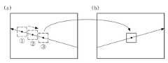
보다 상세히 설명하면, 제어부(140)는 제1 스테레오 카메라(120)에 투영된 이미지 상에서 기 설정된 인간 시선의 주요 응시 범위(예를 들어, 약 ±3 내지 5°)에 대응되는 윈도우를 생성하고, 생성된 윈도우의 중심점을 제1 스테레오 카메라 기준 시선 추적 벡터에 따라 이동시킬 수 있다.In more detail, the
즉, 제1 및 제2 스테레오 카메라(120, 130)에 투영된 스테레오 카메라 기준 시선 추적 벡터 주변 중 가장 유사한 이미지가 시선의 초점으로 파악되는 것이다.That is, the closest image among the stereo camera reference gaze tracking vectors projected on the first and second
이때, 제1 스테레오 카메라(120)에 스테레오 카메라 기준 시선 추적 벡터를 투영하는 것으로 설명하였지만, 이에 한정되지 않고, 제2 스테레오 카메라(130)에 스테레오 카메라 기준 시선 추적 벡터를 투영하는 것도 가능하다 할 것이다.In this case, the stereo camera reference gaze tracking vector is projected onto the
예를 들어, 도 4(a)는 제1 스테레오 카메라(120)에 투영된 스테레오 카메라 기준 시선 추적 벡터를 나타내는 것이고, 도 4(b)는 제2 스테레오 카메라(130)에 투영된 스테레오 카메라 기준 시선 추적 벡터를 나타내는 것이다.For example, FIG. 4A illustrates the stereo camera reference gaze tracking vector projected on the
이때, 제어부(140)는 제1 스테레오 카메라(120)에 투영된 윈도우의 중심점을 제1 스테레오 카메라 기준 시선 추적 벡터에 따라 ⓐ -> ⓑ -> ⓒ로 이동시키는 것이다.In this case, the
또한, 제어부(140)는 이동시킨 윈도우를 제2 스테레오 카메라(130)의 시선 추적 벡터에 대응되도록 템플릿 매칭(Template Matching)을 수행하여, 수행 결과, 가장 높은 위치를 운전자 시선 응시점(Corresponding Point)으로 파악할 수 있다.In addition, the
이때, 템플릿 매칭은 도형 인식 과정에 의해서 주어진 도형(템플릿과 일치하는 도형)을 화상에서 추출하는 과정을 의미하는 것으로, 교차 상관 관계(Cross-correlation) 방식으로 가장 높은 피크점을 찾을 수 있는 것이다.In this case, template matching refers to a process of extracting a figure (a figure matching a template) from an image by a figure recognition process, and finds the highest peak point by a cross-correlation method.
예를 들어, 도 4(b)에서 도시하는 바와 같이, 제어부(140)는 이동시킨 윈도우를 제2 스테레오 카메라(130)의 시선 추적 벡터에 대응하여 템플릿 매칭을 수행할 수 있다.
For example, as illustrated in FIG. 4B, the
또한, 제어부(140)는 3차원 운전자 시선 좌표를 산출하는 데, 이때, 3차원 운전자 시선 좌표는 P(Xp, Yp, Zp)일 수 있다.In addition, the
도 5를 참조하여 설명하면, 3차원 운전자 시선 좌표 P(Xp, Yp, Zp)에서,


이때, Pl(xl, yl)은 P가 제1 스테레오 카메라 촬상면에 투영된 점, Pr(xr, yr)은 P가 제2 스테레오 카메라 촬상면에 투영된 점, f는 카메라 초점거리(Focal Length), T는 제1 및 제2 스테레오 카메라 간의 이격거리, d는 좌표 측정점의 거리를 카메라 초점거리로 나눈 값(d = Zp/f)일 수 있다.Where Pl (xl , yl ) is the point where P is projected onto the first stereo camera image plane, Pr (xr , yr ) is the point where P is projected onto the second stereo camera image plane, and f is the camera focus The focal length, T may be a separation distance between the first and second stereo cameras, and d may be a value obtained by dividing the distance of the coordinate measuring point by the camera focal length (d = Zp / f).
또한, 도 5에서, Ileft는 제1 스테레오 카메라(좌측 카메라)(120)의 이미지 촬상면이고, Iright는 제2 스테레오 카메라(우측 카메라)(130)의 이미지 촬상면이며, Cl은 제1 스테레오 카메라의 이미지 중심점이고, Cr은 제2 스테레오 카메라의 이미지 중심점이며, Ol은 제1 스테레오 카메라의 중심점(Focal Point), Or은 제2 스테레오 카메라의 중심점(Focal Point)을 의미하는 것이다.In addition, in FIG. 5, Ileft is an image pickup surface of the first stereo camera (left camera) 120, Iright is an image pickup surface of the second stereo camera (right camera) 130, and C1 is a first stereo image. The image center point of the camera, Cr is the image center point of the second stereo camera, O1 is the focal point of the first stereo camera, Or is the focal point of the second stereo camera.
한편, 3차원 운전자 시선 좌표는 차량용 인터페이스로 적용될 수 있다.Meanwhile, the 3D driver gaze coordinate may be applied to the vehicle interface.
예를 들어, 도 6에서 도시하는 바와 같이, 3차원 운전자 시선 좌표는 HUD(Head Up Display)의 온 또는 오프 서비스에 적용될 수 있는데, 초점거리가 HUD 지역에 존재할 경우 구동되어, 전방 차가 급제동할 경우 시선 거리에 따라 알람 강도를 변화시키는 형태로 이용될 수 있는 것이다.
For example, as shown in FIG. 6, the 3D driver gaze coordinate may be applied to an on or off service of a head up display (HUD), which is driven when the focal length is present in the HUD area, and the front vehicle suddenly brakes. The alarm intensity may be changed according to the line of sight.
저장부(150)는 시선 추적 카메라(110) 및 제1 및 제2 스테레오 카메라(120, 130)의 위치 정보와 회전 정보를 비롯하여 시스템과 관련된 정보를 저장할 수 있다.The
이때, 시선 추적 카메라(110) 및 제1 및 제2 스테레오 카메라(120, 130)의 위치 정보와 회전 정보는 사전에 물리적 측정 또는 카메라 칼리브레이션 등의 소프트웨어 정보를 통해 파악하여 저장할 수 있다.
In this case, the position information and the rotation information of the
도 2는 본 발명의 실시예에 의한 디스플레이 방법을 설명하기 위한 흐름도이다.2 is a flowchart illustrating a display method according to an embodiment of the present invention.
먼저, 디스플레이 시스템(100)은 시선 추적 카메라(110)를 통해 운전자의 안구를 검출하여 시선 추적 카메라 기준 운전자 시선 정보를 파악할 수 있다(S101).First, the
이때, 시선 추적 카메라 기준 운전자 시선 정보는 시선추적벡터 중심점과 시선 추적 벡터를 포함할 수 있다.
In this case, the gaze tracking camera reference driver gaze information may include a gaze tracking vector center point and a gaze tracking vector.
다음, 기 저장된 시선 추적 카메라(110) 및 제1 및 제2 스테레오 카메라(120, 130)의 위치 정보와 회전 정보를 기초로 시선 추적 카메라 기준 운전자 정보를 제1 및 제2 스테레오 카메라(120, 130) 기준 운전자 시선 정보로 변환할 수 있다(S103).Next, the gaze tracking camera reference driver information is based on the position information and the rotation information of the previously stored
이때, 디스플레이 시스템(100)은 시선 추적 카메라 기준 시선추적벡터 중심점(Location)

또한, 디스플레이 시스템(100)은 시선 추적 카메라 기준 시선 추적 벡터

In addition, the
다음, 제1 및 제2 스테레오 카메라 기준 운전자 시선 정보를 기초로 운전자 시선 응시점을 파악할 수 있다(S105).Next, the driver's gaze gaze point may be determined based on the first and second stereo camera reference driver gaze information (S105).
보다 상세히 설명하면, 제1 및 제2 스테레오 카메라 기준 운전자 시선 정보를 제1 및 제2 스테레오 카메라(120, 130)에 투영시킬 수 있다.In more detail, the first and second stereo camera reference driver gaze information may be projected onto the first and second
다음, 제1 및 제2 스테레오 카메라(120, 130)에 투영된 정보를 기초로 운전자 시선 응시점을 파악할 수 있다.Next, the driver's gaze gaze point may be determined based on the information projected on the first and second
이는, 제1 스테레오 카메라(120)에 투영된 이미지 상에서 기 설정된 인간 시선의 주요 응시 범위에 대응되는 윈도우를 생성하는 단계, 생성된 윈도우의 중심점을 제1 스테레오 카메라 기준 시선 추적 벡터에 따라 이동시키는 단계, 이동시킨 윈도우를 제2 스테레오 카메라(130)의 시선 추적 벡터에 대응되도록 템플릿 매칭(Template Matching)을 수행하는 단계 및 수행 결과, 가장 높은 위치를 운전자 시선 응시점으로 파악하는 단계를 통해 이루어질 수 있다.This may include generating a window corresponding to a main gaze range of a preset human gaze on the image projected on the
예를 들어, 도 4(a)는 제1 스테레오 카메라(120)에 투영된 스테레오 카메라 기준 시선 추적 벡터를 나타내는 것이고, 도 4(b)는 제2 스테레오 카메라(130)에 투영된 스테레오 카메라 기준 시선 추적 벡터를 나타내는 것이다.For example, FIG. 4A illustrates the stereo camera reference gaze tracking vector projected on the
이때, 디스플레이 시스템(100)은 제1 스테레오 카메라(120)에 투영된 윈도우의 중심점을 제1 스테레오 카메라 기준 시선 추적 벡터에 따라 ⓐ -> ⓑ -> ⓒ로 이동시키는 것이다.In this case, the
또한, 도 4(b)에서 도시하는 바와 같이, 디스플레이 시스템(100)은 이동시킨 윈도우를 제2 스테레오 카메라(130)의 시선 추적 벡터에 대응하여 템플릿 매칭을 수행할 수 있다.
In addition, as illustrated in FIG. 4B, the
다음, 운전자 시선 응시점을 3차원 운전자 시선 좌표로 변환할 수 있다(S107).Next, the driver gaze gaze point may be converted into three-dimensional driver gaze coordinates (S107).
상기 3차원 운전자 시선 좌표는 P(Xp, Yp, Zp)일 수 있다.The 3D driver gaze coordinate may be P (Xp, Yp, Zp).
이때,


또한, Pl(xl, yl)은 P가 제1 스테레오 카메라 촬상면에 투영된 점, Pr(xr, yr)은 P가 제2 스테레오 카메라 촬상면에 투영된 점, f는 카메라 초점거리(Focal Length), T는 제1 및 제2 스테레오 카메라 간의 이격거리, d는 좌표 측정점의 거리를 카메라 초점거리로 나눈 값일 수 있다.
Also, Pl (xl , yl ) is the point where P is projected onto the first stereo camera image plane, Pr (xr , yr ) is the point where P is projected onto the second stereo camera image plane, and f is the camera focus. The focal length, T may be a separation distance between the first and second stereo cameras, and d may be a value obtained by dividing the distance of the coordinate measuring point by the camera focal length.
이상 본 발명을 구체적인 실시예를 통하여 상세히 설명하였으나, 이는 본 발명을 구체적으로 설명하기 위한 것으로, 본 발명은 이에 한정되지 않으며, 본 발명의 기술적 사상 내에서 당 분야의 통상의 지식을 가진 자에 의해 그 변형이나 개량이 가능함이 명백하다.
While the present invention has been particularly shown and described with reference to exemplary embodiments thereof, it is to be understood that the same is by way of illustration and example only and is not to be construed as limiting the present invention. It is obvious that the modification or improvement is possible.
본 발명의 단순한 변형 내지 변경은 모두 본 발명의 영역에 속하는 것으로 본 발명의 구체적인 보호 범위는 첨부된 특허청구범위에 의하여 명확해질 것이다.It will be understood by those skilled in the art that various changes in form and details may be made therein without departing from the spirit and scope of the invention as defined by the appended claims.
100 : 디스플레이 시스템
110 : 시선 추적 카메라
120 : 제1 스테레오 카메라
130 : 제2 스테레오 카메라
140 : 제어부
150 : 저장부100: display system
110: eye tracking camera
120: first stereo camera
130: second stereo camera
140:
150:
Claims (16)
Translated fromKorean시선 추적 카메라 기준 운전자 시선 정보로부터 변경된 스테레오 카메라 기준 운전자 시선 정보를 기초로 운전자 시야에 대응되는 범위를 촬영하여 제공하는 제1 및 제2 스테레오 카메라;
기 저장된 시선 추적 카메라 및 상기 제1 및 제2 스테레오 카메라의 위치 정보와 회전 정보를 기초로 상기 시선 추적 카메라 기준 운전자 정보를 상기 제1 및 제2 스테레오 카메라 기준 운전자 시선 정보로 변환하여 상기 제1 및 제2 스테레오 카메라에 투영시키고, 이를 통해 3차원 운전자 시선 좌표를 산출하는 제어부; 및
상기 시선 추적 카메라 및 상기 제1 및 제2 스테레오 카메라의 위치 정보와 회전 정보를 비롯하여 시스템과 관련된 정보를 저장하는 저장부를 포함하되,
상기 제어부는,
상기 제1 및 제2 스테레오 카메라에 투영된 스테레오 카메라 기준 시선 추적 벡터에서 운전자 시선 응시점을 산출하고, 이를 기초로 3차원 운전자 시선 좌표를 산출하는 것을 특징으로 하는 디스플레이 시스템.
A gaze tracking camera detecting an eye of a driver;
A first and second stereo cameras configured to photograph and provide a range corresponding to a driver's view based on the stereo camera reference driver gaze information changed from the gaze tracking camera reference driver gaze information;
The gaze tracking camera reference driver information is converted into the first and second stereo camera reference driver gaze information based on the stored position information and rotation information of the gaze tracking camera and the first and second stereo cameras. A control unit for projecting onto a second stereo camera and calculating three-dimensional driver gaze coordinates through the second stereo camera; And
Including a storage unit for storing information related to the system, including position information and rotation information of the eye tracking camera and the first and second stereo camera,
Wherein,
And a driver gaze gaze point is calculated from the stereo camera reference gaze tracking vectors projected on the first and second stereo cameras, and the 3D driver gaze coordinates are calculated based on the driver gaze gaze points.
상기 시선 추적 카메라 기준 운전자 시선 정보는 시선추적벡터 중심점과 시선 추적 벡터를 포함하며,
상기 제어부는,
상기 시선 추적 카메라 기준 시선추적벡터 중심점을 스테레오 카메라 기준 시선추적벡터 중심점으로 변환하는 디스플레이 시스템.
The method according to claim 1,
The gaze tracking camera reference driver gaze information includes a gaze tracking vector center point and a gaze tracking vector.
Wherein,
And a display system for converting the gaze tracking camera reference gaze tracking vector center point into a stereo camera reference gaze tracking vector center point.
상기 제어부는,
상기 시선 추적 카메라 기준 시선추적벡터 중심점(Location)


상기 수학식 1은,

이며, 상기


The method according to claim 2,
Wherein,
Center of eye tracking vector based on the eye tracking camera
In Equation (1)
, And
상기 시선 추적 카메라 기준 운전자 시선 정보는 시선추적벡터 중심점과 시선 추적 벡터를 포함하며,
상기 제어부는,
상기 시선 추적 카메라 기준 시선 추적 벡터를 스테레오 카메라 기준 시선 추적 벡터로 변환하는 디스플레이 시스템.
The method according to claim 1,
The gaze tracking camera reference driver gaze information includes a gaze tracking vector center point and a gaze tracking vector.
Wherein,
And a display system to convert the gaze tracking camera reference gaze tracking vector into a stereo camera reference gaze tracking vector.
상기 제어부는,
상기 시선 추적 카메라 기준 시선 추적 벡터


상기 수학식 2는,

이며, 상기

The method of claim 4,
Wherein,
The eye tracking camera reference eye tracking vector
Equation (2)
, And
상기 제어부는,
상기 제1 스테레오 카메라에 투영된 이미지 상에서 기 설정된 인간 시선의 주요 응시 범위에 대응되는 윈도우를 생성하고, 생성된 윈도우의 중심점을 제1 스테레오 카메라 기준 시선 추적 벡터에 따라 이동시키며, 이동시킨 윈도우를 제2 스테레오 카메라의 시선 추적 벡터에 대응되도록 템플릿 매칭(Template Matching)을 수행하여, 매칭한 결과가 가장 높은 위치를 운전자 시선 응시점으로 파악하는 디스플레이 시스템.
The method according to claim 1,
Wherein,
Create a window corresponding to a main gaze range of a preset human gaze on the image projected on the first stereo camera, move the center point of the generated window according to the first stereo camera reference gaze tracking vector, and remove the moved window. 2. A display system that performs template matching so as to correspond to a gaze tracking vector of a stereo camera, and identifies a position where the matched result is the highest as a driver gaze point.
상기 3차원 운전자 시선 좌표는 P(Xp, Yp, Zp)이며,
상기


상기 Pl(xl, yl)은 P가 제1 스테레오 카메라 촬상면에 투영된 점, Pr(xr, yr)은 P가 제2 스테레오 카메라 촬상면에 투영된 점, f는 카메라 초점거리(Focal Length), T는 제1 및 제2 스테레오 카메라 간의 이격거리, d는 좌표 측정점의 거리를 카메라 초점거리로 나눈 값인 디스플레이 시스템.
The method according to claim 1,
The three-dimensional driver line of sight coordinates are P (Xp, Yp, Zp),
remind
Pl (xl , yl ) is the point where P is projected on the first stereo camera image plane, Pr (xr , yr ) is the point where P is projected on the second stereo camera image plane, f is the camera focal length (Focal Length), T is the separation distance between the first and second stereo camera, d is the distance of the coordinate measuring point divided by the camera focal length.
상기 시선 추적 카메라를 통해 운전자의 안구를 검출하여 시선 추적 카메라 기준 운전자 시선 정보를 파악하는 단계;
기 저장된 시선 추적 카메라 및 상기 제1 및 제2 스테레오 카메라의 위치 정보와 회전 정보를 기초로 상기 시선 추적 카메라 기준 운전자 정보를 상기 제1 및 제2 스테레오 카메라 기준 운전자 시선 정보로 변환하는 단계;
상기 제1 및 제2 스테레오 카메라 기준 운전자 시선 정보를 기초로 운전자 시선 응시점을 파악하는 단계; 및
상기 운전자 시선 응시점을 3차원 운전자 시선 좌표로 변환하는 단계를 포함하되,
상기 운전자 시선 응시점을 파악하는 단계는,
상기 제1 및 제2 스테레오 카메라 기준 운전자 시선 정보를 상기 제1 및 제2 스테레오 카메라에 투영시키는 단계; 및
상기 제1 및 제2 스테레오 카메라에 투영된 정보를 기초로 운전자 시선 응시점을 파악하는 단계를 포함하는 디스플레이 방법.
A display method for providing a 3D driver gaze in a display system including a gaze tracking camera and a first and second stereo camera,
Detecting eyeballs of the driver through the eye tracking camera to identify eyeball tracking camera reference driver eye information;
Converting the gaze tracking camera reference driver information into the first and second stereo camera reference driver gaze information based on position information and rotation information of a pre-stored gaze tracking camera and the first and second stereo cameras;
Determining a driver's gaze gaze point based on the first and second stereo camera reference driver gaze information; And
Converting the driver's gaze gaze point into three-dimensional driver gaze coordinates,
Identifying the driver gaze point of view,
Projecting the first and second stereo camera reference driver gaze information to the first and second stereo cameras; And
And determining a driver's gaze gaze point based on the information projected on the first and second stereo cameras.
상기 시선 추적 카메라 기준 운전자 시선 정보는 시선추적벡터 중심점과 시선 추적 벡터를 포함하며,
상기 제1 및 제2 스테레오 카메라 기준 운전자 시선 정보로 변환하는 단계에서,
상기 시선 추적 카메라 기준 시선추적벡터 중심점을 스테레오 카메라 기준 시선추적벡터 중심점으로 변환하는 디스플레이 방법.
The method of claim 9,
The gaze tracking camera reference driver gaze information includes a gaze tracking vector center point and a gaze tracking vector.
In the converting into the first and second stereo camera reference driver gaze information,
And a display method of converting the eye tracking camera reference eye tracking vector center point into a stereo camera reference eye tracking vector center point.
상기 제1 및 제2 스테레오 카메라 기준 운전자 시선 정보로 변환하는 단계에서,
상기 시선 추적 카메라 기준 시선추적벡터 중심점(Location)


상기 수학식 1은,

이며, 상기


The method of claim 10,
In the converting into the first and second stereo camera reference driver gaze information,
Center of eye tracking vector based on the eye tracking camera
In Equation (1)
, And
상기 시선 추적 카메라 기준 운전자 시선 정보는 시선추적벡터 중심점과 시선 추적 벡터를 포함하며,
상기 제1 및 제2 스테레오 카메라 기준 운전자 시선 정보로 변환하는 단계에서,
상기 시선 추적 카메라 기준 시선 추적 벡터를 스테레오 카메라 기준 시선 추적 벡터로 변환하는 디스플레이 방법.
The method of claim 9,
The gaze tracking camera reference driver gaze information includes a gaze tracking vector center point and a gaze tracking vector.
In the converting into the first and second stereo camera reference driver gaze information,
And a display method of converting the gaze tracking camera reference gaze tracking vector into a stereo camera reference gaze tracking vector.
상기 제1 및 제2 스테레오 카메라 기준 운전자 시선 정보로 변환하는 단계에서,
상기 시선 추적 카메라 기준 시선 추적 벡터


상기 수학식 2는,

이며, 상기

The method of claim 12,
In the converting into the first and second stereo camera reference driver gaze information,
The eye tracking camera reference eye tracking vector
Equation (2)
, And
상기 제1 및 제2 스테레오 카메라에 투영된 정보를 기초로 운전자 시선 응시점을 파악하는 단계는,
상기 제1 스테레오 카메라에 투영된 이미지 상에서 기 설정된 인간 시선의 주요 응시 범위에 대응되는 윈도우를 생성하는 단계;
생성된 윈도우의 중심점을 제1 스테레오 카메라 기준 시선 추적 벡터에 따라 이동시키는 단계;
이동시킨 윈도우를 제2 스테레오 카메라의 시선 추적 벡터에 대응되도록 템플릿 매칭(Template Matching)을 수행하는 단계; 및
매칭한 결과가 가장 높은 위치를 운전자 시선 응시점으로 파악하는 단계;
를 포함하는 디스플레이 방법.
The method of claim 9,
Identifying the driver's gaze gaze point based on the information projected on the first and second stereo cameras,
Generating a window corresponding to a main gaze range of a preset human gaze on the image projected by the first stereo camera;
Moving the center point of the generated window according to the first stereo camera reference gaze tracking vector;
Performing template matching so that the moved window corresponds to the gaze tracking vector of the second stereo camera; And
Identifying a position where the matched result is highest as the driver's gaze gaze point;
/ RTI >
상기 3차원 운전자 시선 좌표는 P(Xp, Yp, Zp)이며,
상기


상기 Pl(xl, yl)은 P가 제1 스테레오 카메라 촬상면에 투영된 점, Pr(xr, yr)은 P가 제2 스테레오 카메라 촬상면에 투영된 점, f는 카메라 초점거리(Focal Length), T는 제1 및 제2 스테레오 카메라 간의 이격거리, d는 좌표 측정점의 거리를 카메라 초점거리로 나눈 값인 디스플레이 방법.The method of claim 9,
The three-dimensional driver line of sight coordinates are P (Xp, Yp, Zp),
remind
Pl (xl , yl ) is the point where P is projected on the first stereo camera image plane, Pr (xr , yr ) is the point where P is projected on the second stereo camera image plane, f is the camera focal length (Focal Length), T is the separation distance between the first and second stereo camera, d is the distance of the coordinate measuring point divided by the camera focal length.
Priority Applications (3)
| Application Number | Priority Date | Filing Date | Title |
|---|---|---|---|
| KR1020120143921AKR101382772B1 (en) | 2012-12-11 | 2012-12-11 | Display system and method |
| US13/871,678US9160929B2 (en) | 2012-12-11 | 2013-04-26 | Line-of-sight tracking system and method |
| CN201310182182.4ACN103871045B (en) | 2012-12-11 | 2013-05-16 | Display system and method |
Applications Claiming Priority (1)
| Application Number | Priority Date | Filing Date | Title |
|---|---|---|---|
| KR1020120143921AKR101382772B1 (en) | 2012-12-11 | 2012-12-11 | Display system and method |
Publications (1)
| Publication Number | Publication Date |
|---|---|
| KR101382772B1true KR101382772B1 (en) | 2014-04-08 |
Family
ID=50656975
Family Applications (1)
| Application Number | Title | Priority Date | Filing Date |
|---|---|---|---|
| KR1020120143921AActiveKR101382772B1 (en) | 2012-12-11 | 2012-12-11 | Display system and method |
Country Status (3)
| Country | Link |
|---|---|
| US (1) | US9160929B2 (en) |
| KR (1) | KR101382772B1 (en) |
| CN (1) | CN103871045B (en) |
Cited By (3)
| Publication number | Priority date | Publication date | Assignee | Title |
|---|---|---|---|---|
| DE102014207397A1 (en)* | 2014-04-17 | 2015-10-22 | Bayerische Motoren Werke Aktiengesellschaft | Method, device, vehicle operating system, computer program for operating a vehicle and computer program product |
| KR20180003671A (en)* | 2016-06-30 | 2018-01-10 | 전자부품연구원 | Covering object transparent display device, method and system according to gaze direction |
| KR102426071B1 (en)* | 2021-07-21 | 2022-07-27 | 정희석 | Artificial intelligence based gaze recognition device and method, and unmanned information terminal using the same |
Families Citing this family (12)
| Publication number | Priority date | Publication date | Assignee | Title |
|---|---|---|---|---|
| CN105700677A (en)* | 2015-12-29 | 2016-06-22 | 努比亚技术有限公司 | Mobile terminal and control method thereof |
| US10007854B2 (en)* | 2016-07-07 | 2018-06-26 | Ants Technology (Hk) Limited | Computer vision based driver assistance devices, systems, methods and associated computer executable code |
| US9874934B1 (en) | 2016-07-29 | 2018-01-23 | International Business Machines Corporation | System, method, and recording medium for tracking gaze with respect to a moving plane with a camera with respect to the moving plane |
| EP3305176A1 (en)* | 2016-10-04 | 2018-04-11 | Essilor International | Method for determining a geometrical parameter of an eye of a subject |
| KR20190013224A (en)* | 2017-08-01 | 2019-02-11 | 엘지전자 주식회사 | Mobile terminal |
| US11620419B2 (en) | 2018-01-24 | 2023-04-04 | Toyota Research Institute, Inc. | Systems and methods for identifying human-based perception techniques |
| JP7115276B2 (en)* | 2018-12-10 | 2022-08-09 | トヨタ自動車株式会社 | Driving support device, wearable device, driving support system, driving support method and program |
| BR112021016773A2 (en)* | 2019-03-14 | 2021-11-16 | Nec Corp | Information processing device, information processing system, information processing method and storage medium |
| PH12019050076A1 (en)* | 2019-05-06 | 2020-12-02 | Samsung Electronics Co Ltd | Enhancing device geolocation using 3d map data |
| CN111522443B (en)* | 2020-04-13 | 2024-04-05 | 京东方科技集团股份有限公司 | Display method, system, equipment and storage medium of vehicle A column display assembly |
| US20240430574A1 (en)* | 2023-06-20 | 2024-12-26 | Rivian Ip Holdings, Llc | Vehicle camera system |
| CN119289857B (en)* | 2024-10-23 | 2025-07-11 | 泽景(西安)汽车电子有限责任公司 | Eye point position determining device and system |
Citations (4)
| Publication number | Priority date | Publication date | Assignee | Title |
|---|---|---|---|---|
| JP2004259043A (en) | 2003-02-26 | 2004-09-16 | Toyota Motor Corp | Direction detection device and direction detection method |
| JP2004254960A (en) | 2003-02-26 | 2004-09-16 | Toyota Motor Corp | Device and method for detecting direction of visual line |
| JP2005278898A (en) | 2004-03-30 | 2005-10-13 | Honda Motor Co Ltd | Gaze detection device |
| KR20060105271A (en)* | 2005-04-04 | 2006-10-11 | 엘지전자 주식회사 | Eye Position Estimation System and Eye Position Estimation Method Using 3D Position Information |
Family Cites Families (16)
| Publication number | Priority date | Publication date | Assignee | Title |
|---|---|---|---|---|
| JP4015051B2 (en)* | 2002-04-22 | 2007-11-28 | 松下電器産業株式会社 | Camera correction device |
| US6989754B2 (en)* | 2003-06-02 | 2006-01-24 | Delphi Technologies, Inc. | Target awareness determination system and method |
| JP2008136789A (en)* | 2006-12-05 | 2008-06-19 | Nec Corp | Eyeball parameter estimation apparatus and method |
| US7682025B2 (en)* | 2007-02-04 | 2010-03-23 | Miralex Systems Incorporated | Gaze tracking using multiple images |
| KR100941236B1 (en) | 2008-03-31 | 2010-02-10 | 현대자동차주식회사 | Front endless driving detection alarm system |
| JP5354514B2 (en)* | 2008-03-31 | 2013-11-27 | 現代自動車株式会社 | Armpit driving detection alarm system |
| CN201307266Y (en)* | 2008-06-25 | 2009-09-09 | 韩旭 | Binocular sightline tracking device |
| US8629784B2 (en)* | 2009-04-02 | 2014-01-14 | GM Global Technology Operations LLC | Peripheral salient feature enhancement on full-windshield head-up display |
| JP2010281685A (en) | 2009-06-04 | 2010-12-16 | National Univ Corp Shizuoka Univ | Position measuring system and position measuring method |
| US8384534B2 (en)* | 2010-01-14 | 2013-02-26 | Toyota Motor Engineering & Manufacturing North America, Inc. | Combining driver and environment sensing for vehicular safety systems |
| CN102169364B (en)* | 2010-02-26 | 2013-03-27 | 原相科技股份有限公司 | Interaction module applied to stereoscopic interaction system and method of interaction module |
| US20110310001A1 (en)* | 2010-06-16 | 2011-12-22 | Visteon Global Technologies, Inc | Display reconfiguration based on face/eye tracking |
| KR101628394B1 (en) | 2010-11-22 | 2016-06-08 | 현대자동차주식회사 | Method for tracking distance of eyes of driver |
| KR20120062541A (en) | 2010-12-06 | 2012-06-14 | 현대자동차주식회사 | Display system based on gaze direction vector |
| KR101544524B1 (en)* | 2010-12-16 | 2015-08-17 | 한국전자통신연구원 | Display system for augmented reality in vehicle, and method for the same |
| JP5706715B2 (en) | 2011-02-25 | 2015-04-22 | 株式会社ジオ技術研究所 | 3D map display system |
- 2012
- 2012-12-11KRKR1020120143921Apatent/KR101382772B1/enactiveActive
- 2013
- 2013-04-26USUS13/871,678patent/US9160929B2/enactiveActive
- 2013-05-16CNCN201310182182.4Apatent/CN103871045B/enactiveActive
Patent Citations (4)
| Publication number | Priority date | Publication date | Assignee | Title |
|---|---|---|---|---|
| JP2004259043A (en) | 2003-02-26 | 2004-09-16 | Toyota Motor Corp | Direction detection device and direction detection method |
| JP2004254960A (en) | 2003-02-26 | 2004-09-16 | Toyota Motor Corp | Device and method for detecting direction of visual line |
| JP2005278898A (en) | 2004-03-30 | 2005-10-13 | Honda Motor Co Ltd | Gaze detection device |
| KR20060105271A (en)* | 2005-04-04 | 2006-10-11 | 엘지전자 주식회사 | Eye Position Estimation System and Eye Position Estimation Method Using 3D Position Information |
Cited By (3)
| Publication number | Priority date | Publication date | Assignee | Title |
|---|---|---|---|---|
| DE102014207397A1 (en)* | 2014-04-17 | 2015-10-22 | Bayerische Motoren Werke Aktiengesellschaft | Method, device, vehicle operating system, computer program for operating a vehicle and computer program product |
| KR20180003671A (en)* | 2016-06-30 | 2018-01-10 | 전자부품연구원 | Covering object transparent display device, method and system according to gaze direction |
| KR102426071B1 (en)* | 2021-07-21 | 2022-07-27 | 정희석 | Artificial intelligence based gaze recognition device and method, and unmanned information terminal using the same |
Also Published As
| Publication number | Publication date |
|---|---|
| US9160929B2 (en) | 2015-10-13 |
| CN103871045A (en) | 2014-06-18 |
| CN103871045B (en) | 2018-09-04 |
| US20140160249A1 (en) | 2014-06-12 |
Similar Documents
| Publication | Publication Date | Title |
|---|---|---|
| KR101382772B1 (en) | Display system and method | |
| US9563981B2 (en) | Information processing apparatus, information processing method, and program | |
| JP6304628B2 (en) | Display device and display method | |
| JP6344417B2 (en) | Vehicle display device | |
| TWI496108B (en) | AR image processing apparatus and method | |
| US11244145B2 (en) | Information processing apparatus, information processing method, and recording medium | |
| EP3185211B1 (en) | Corneal reflection position estimation system, corneal reflection position estimation method, corneal reflection position estimation program, pupil detection system, pupil detection method, pupil detection program, gaze detection system, gaze detection method, gaze detection program, face orientation detection system, face orientation detection method, and face orientation detection program | |
| EP2937815A3 (en) | Methods and systems for object detection using laser point clouds | |
| JP2015056057A (en) | Posture estimation method and robot | |
| RU2015138973A (en) | HEAD-STRENGTHED DISPLAY AND METHOD OF MANAGEMENT FOR STRENGTHENED-HEAD DISPLAY | |
| EP2239538A1 (en) | Apparatus for detecting three-dimensional distance | |
| CN102713975B (en) | Image clearing system, image method for sorting and computer program | |
| CN111527374A (en) | Sight direction correction device, sight direction correction method, and sight direction correction program | |
| JP2016091192A (en) | Virtual image display apparatus, control method, program, and storage medium | |
| US20140294286A1 (en) | Three dimension measurement method, three dimension measurement program and robot device | |
| JP5299101B2 (en) | Peripheral display device | |
| JP2018106611A5 (en) | ||
| US20170330334A1 (en) | Movement direction determination method and movement direction determination device | |
| JP6494764B2 (en) | Display control device, display device, and display control method | |
| KR20130067842A (en) | Image based object information detecting method and apparatus | |
| JP6458577B2 (en) | Image ranging device | |
| JP2006027481A (en) | Object warning device and object warning method | |
| KR101316387B1 (en) | Method of object recognition using vision sensing and distance sensing | |
| KR20160063039A (en) | Method of Road Recognition using 3D Data | |
| JP2015206764A (en) | Object person existence range estimation device and object person existence range estimation method |
Legal Events
| Date | Code | Title | Description |
|---|---|---|---|
| A201 | Request for examination | ||
| PA0109 | Patent application | Patent event code:PA01091R01D Comment text:Patent Application Patent event date:20121211 | |
| PA0201 | Request for examination | ||
| E902 | Notification of reason for refusal | ||
| PE0902 | Notice of grounds for rejection | Comment text:Notification of reason for refusal Patent event date:20131128 Patent event code:PE09021S01D | |
| E701 | Decision to grant or registration of patent right | ||
| PE0701 | Decision of registration | Patent event code:PE07011S01D Comment text:Decision to Grant Registration Patent event date:20140225 | |
| GRNT | Written decision to grant | ||
| PR0701 | Registration of establishment | Comment text:Registration of Establishment Patent event date:20140401 Patent event code:PR07011E01D | |
| PR1002 | Payment of registration fee | Payment date:20140401 End annual number:3 Start annual number:1 | |
| PG1601 | Publication of registration | ||
| FPAY | Annual fee payment | Payment date:20180329 Year of fee payment:5 | |
| PR1001 | Payment of annual fee | Payment date:20180329 Start annual number:5 End annual number:5 | |
| FPAY | Annual fee payment | Payment date:20190327 Year of fee payment:6 | |
| PR1001 | Payment of annual fee | Payment date:20190327 Start annual number:6 End annual number:6 | |
| PR1001 | Payment of annual fee | Payment date:20200330 Start annual number:7 End annual number:7 | |
| PR1001 | Payment of annual fee | Payment date:20210329 Start annual number:8 End annual number:8 | |
| PR1001 | Payment of annual fee | Payment date:20220328 Start annual number:9 End annual number:9 | |
| PR1001 | Payment of annual fee | Payment date:20230327 Start annual number:10 End annual number:10 | |
| PR1001 | Payment of annual fee | Payment date:20240325 Start annual number:11 End annual number:11 | |
| PR1001 | Payment of annual fee | Payment date:20250325 Start annual number:12 End annual number:12 |