KR101380024B1 - System for controlling super conduction generator - Google Patents
System for controlling super conduction generatorDownload PDFInfo
- Publication number
- KR101380024B1 KR101380024B1KR1020120150376AKR20120150376AKR101380024B1KR 101380024 B1KR101380024 B1KR 101380024B1KR 1020120150376 AKR1020120150376 AKR 1020120150376AKR 20120150376 AKR20120150376 AKR 20120150376AKR 101380024 B1KR101380024 B1KR 101380024B1
- Authority
- KR
- South Korea
- Prior art keywords
- armature winding
- voltage
- superconducting generator
- exciter
- rotor
- Prior art date
- Legal status (The legal status is an assumption and is not a legal conclusion. Google has not performed a legal analysis and makes no representation as to the accuracy of the status listed.)
- Expired - Fee Related
Links
Images


Classifications
- H—ELECTRICITY
- H02—GENERATION; CONVERSION OR DISTRIBUTION OF ELECTRIC POWER
- H02P—CONTROL OR REGULATION OF ELECTRIC MOTORS, ELECTRIC GENERATORS OR DYNAMO-ELECTRIC CONVERTERS; CONTROLLING TRANSFORMERS, REACTORS OR CHOKE COILS
- H02P9/00—Arrangements for controlling electric generators for the purpose of obtaining a desired output
- H02P9/14—Arrangements for controlling electric generators for the purpose of obtaining a desired output by variation of field
- H—ELECTRICITY
- H02—GENERATION; CONVERSION OR DISTRIBUTION OF ELECTRIC POWER
- H02M—APPARATUS FOR CONVERSION BETWEEN AC AND AC, BETWEEN AC AND DC, OR BETWEEN DC AND DC, AND FOR USE WITH MAINS OR SIMILAR POWER SUPPLY SYSTEMS; CONVERSION OF DC OR AC INPUT POWER INTO SURGE OUTPUT POWER; CONTROL OR REGULATION THEREOF
- H02M7/00—Conversion of AC power input into DC power output; Conversion of DC power input into AC power output
- H02M7/02—Conversion of AC power input into DC power output without possibility of reversal
- H—ELECTRICITY
- H02—GENERATION; CONVERSION OR DISTRIBUTION OF ELECTRIC POWER
- H02M—APPARATUS FOR CONVERSION BETWEEN AC AND AC, BETWEEN AC AND DC, OR BETWEEN DC AND DC, AND FOR USE WITH MAINS OR SIMILAR POWER SUPPLY SYSTEMS; CONVERSION OF DC OR AC INPUT POWER INTO SURGE OUTPUT POWER; CONTROL OR REGULATION THEREOF
- H02M7/00—Conversion of AC power input into DC power output; Conversion of DC power input into AC power output
- H02M7/42—Conversion of DC power input into AC power output without possibility of reversal
Landscapes
- Engineering & Computer Science (AREA)
- Power Engineering (AREA)
- Superconductive Dynamoelectric Machines (AREA)
Abstract
Description
Translated fromKorean본 발명은 초전도 발전기 제어 시스템에 관한 것으로, 더욱 상세하게는 이중 전기자 권선을 가지는 고정자를 포함하는 초전도 발전기를 포함하는 초전도 발전기 제어 시스템에 관한 것이다.The present invention relates to a superconducting generator control system, and more particularly to a superconducting generator control system comprising a superconducting generator comprising a stator having a double armature winding.
기존의 상전도 발전기 제어 시스템은 초전도 발전기 제어 시스템에 비해 주 발전기의 계자 권선의 시정수가 현저히 낮기 때문에 자동전압조정장치(Auto Voltage Regulator, AVR)를 이용하여 부하 조건에 따라 변화하는 주 발전기의 출력 전압을 일정하게 유지하도록 제어한다.Since the time constant of the field winding of the main generator is significantly lower than that of the superconducting generator control system, the conventional high-voltage generator control system uses an automatic voltage regulator (AVR) To be constant.
도 1은 종래의 상전도 발전기 제어 시스템의 구성을 나타낸 도면이다.1 is a diagram showing a configuration of a conventional three-phase generator control system.
도 1을 참조하면, 종래의 상전도 발전기 제어 시스템은 계통 부하의 변화에 따라 변화하는 주 발전기(130)의 출력 전압을 일정하게 유지하기 위해, 전압 센서(140)를 이용하여 주 발전기(130)의 출력 전압을 계측하고, 자동전압조정장치(150)를 이용하여 여자기(110)의 고정된 계자 전류의 크기를 제어한다.Referring to FIG. 1, a conventional three-phase generator control system includes a
여자기(110)의 회전하는 전기자 권선(112)에서 발생되는 교류 전력은 축에 부착된 정류기(120)를 거쳐 직류 전력으로 변환되고, 변환된 직류 전력은 주 발전기(130)의 회전하는 계자 권선(132)에 인가된다.The alternating current power generated in the rotating armature winding 112 of the
상술한 바와 같이, 여자기(110)의 전기자 권선(112)에서 발생한 교류 전력을 직접 제어하는 경우, 회전축에 정류기(120)가 장착되어야 하고, 자동전압조정장치(150)가 무선으로 여자기(110)의 회전하는 전기자 권선(112)의 출력을 직접 제어해야 한다.As described above, in the case of directly controlling the AC power generated in the armature winding 112 of the
그러나, 초전도 발전기 제어 시스템은 초전도 계자 권선의 고 인덕턴스(High Inductance)와 제로 저항(Zero Resistance) 특성에 의한 큰 시정수로 인해 상전도 발전기 제어 시스템과 같은 인가 전압 변환 방식의 제어 기법으로 초전도 발전기의 출력 전압을 일정하게 제어하는 것은 사실상 불가능하다.However, due to the high time constant due to the high inductance and zero resistance of the superconducting field winding, the control system of the superconducting generator is a control technique of the applied voltage conversion method such as the normal phase generator control system. It is practically impossible to control the output voltage constantly.
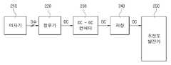
도 2는 종래의 초전도 발전기 제어 시스템의 구성을 나타낸 도면이다.2 is a diagram showing a configuration of a conventional superconducting generator control system.
도 2를 참조하면, 종래의 초전도 발전기 제어 시스템에서는 DC-DC 컨버터(230)가 여자기(210)에서 출력된 전력을 직접 전압 변조하여 제어하고, 초전도 발전기(250)의 입력단에는 시정수를 저하시키기 위한 대용량의 저항(240)이 삽입된다.Referring to FIG. 2, in the conventional superconducting generator control system, the DC-
DC-DC 컨버터(230)는 초전도 발전기(250)의 출력 전압을 계측한 후 무선으로 제어 신호를 DC-DC 컨버터(230)로 송신하는 외부에 고정된 제어 시스템에 의해 제어된다.The DC-
그러나, 종래의 초전도 발전기 제어 시스템은 수백 KW급 용량의 DC-DC 컨버터 및 시정수 저하용 저항을 회전축에 고정하는 데 구조적인 곤란성이 있고, DC-DC 컨버터와 시정수 저하용 저항을 고정시킬 때 브러시와 같은 별도의 기계적인 장치를 필요로 하며, 또한 저항의 용량만큼 손실이 발생되어 시스템의 효율 저하로 인해 사실상 적용이 불가능하다.However, in the conventional superconducting generator control system, there is a structural difficulty in fixing a DC-DC converter having a capacity of several hundreds of kW and a resistance for lowering the time constant to the rotary shaft. In fixing the DC-DC converter and the resistance for lowering the time constant A separate mechanical device such as a brush is required, and a loss due to the capacity of the resistor is generated, which makes it practically impossible to apply the system due to a reduction in the efficiency of the system.
이와 같은 문제점을 해결하기 위해, 초전도 발전기의 출력단에 인버터를 적용하는 것을 고려해볼 수 있으나, 발전기 용량급의 인버터가 필요하여 시스템 단가가 급격히 상승하는 문제점이 있었다.In order to solve such a problem, it may be considered to apply an inverter to the output terminal of the superconducting generator, but there is a problem that the system cost increases rapidly because an inverter of the generator capacity class is required.
본 발명은 상기한 바와 같은 문제점을 해결하기 위하여 안출된 것으로서, 인버터 용량을 저감하여 시스템 단가를 저감할 수 있는 초전도 발전기 제어 시스템을 제공하는 데 그 목적이 있다.The present invention has been made to solve the above problems, and an object thereof is to provide a superconducting generator control system that can reduce the unit cost by reducing the inverter capacity.
이와 같은 목적을 달성하기 위한, 본 발명의 실시예에 따르면, 본 발명에 따른 초전도 발전기 제어 시스템은, 단일 계자 권선을 가지는 회전자와, 기저부하용 전력을 출력하는 제1 전기자 권선 및 변동부하용 전력을 출력하는 제2 전기자 권선으로 구성되는 이중 전기자 권선을 가지는 고정자를 포함하는 초전도 발전기; 상기 단일 계자 권선에 전력을 공급하는 단일 전기자 권선을 가지는 회전자를 포함하는 여자기; 상기 초전도 발전기의 회전자와 상기 여자기의 회전자의 편심을 보정하는 무게추; 상기 무게추에 장착되고, 상기 여자기의 단일 전기자 권선에서 생성된 3상 교류 전압을 초전도 발전기의 단일 계자 권선에 필요한 직류 전압으로 변환하는 정류기; 및 상기 초전도 발전기의 제2 전기자 권선에 연결되어, 계통부하에 따라 변하는 전압을 일정한 전압으로 출력하여 전력계통에 연결하는 인버터를 포함한다.In order to achieve the above object, according to an embodiment of the present invention, a superconducting generator control system according to the present invention, a rotor having a single field winding, a first armature winding and a variable load power for outputting the base load power A superconducting generator comprising a stator having a double armature winding configured as a second armature winding to output a; An exciter comprising a rotor having a single armature winding for powering the single field winding; A weight for correcting the eccentricity of the rotor of the superconducting generator and the rotor of the exciter; A rectifier mounted on the weight and converting a three-phase alternating voltage generated in the single armature winding of the exciter into a DC voltage required for the single field winding of the superconducting generator; And an inverter connected to the second armature winding of the superconducting generator and outputting a voltage varying according to a system load at a constant voltage to be connected to the power system.
이상에서 설명한 바와 같이 본 발명에 의하면, 이중 전기자 권선을 가지는 고정자를 포함하는 초전도 발전기를 포함하는 초전도 발전기 제어 시스템을 제공함으로써, 변동 부하 용량의 인버터 용량으로 일정 출력의 전압 제어가 가능하게 하여 인버터 용량 저감에 따라 시스템 단가를 낮출 수 있는 효과가 있다.As described above, according to the present invention, by providing a superconducting generator control system including a superconducting generator including a stator having a double armature winding, it is possible to control the voltage of a constant output with the inverter capacity of the variable load capacity, the inverter capacity The reduction has the effect of lowering the system cost.
도 1은 종래의 상전도 발전기 제어 시스템의 구성을 나타낸 도면,
도 2는 종래의 초전도 발전기 제어 시스템의 구성을 나타낸 도면,
도 3은 본 발명의 실시예에 따른 초전도 발전기 제어 시스템의 구성을 나타낸 도면,
도 4는 본 발명의 실시예에 따른 초전도 발전기의 전기자 권선의 자세한 구성을 나타낸 도면이다.1 is a diagram showing a configuration of a conventional three-phase generator control system,
2 is a diagram showing a configuration of a conventional superconducting generator control system,
3 is a diagram illustrating a configuration of a superconducting generator control system according to an embodiment of the present invention.
4 is a view showing a detailed configuration of the armature winding of the superconducting generator according to the embodiment of the present invention.
이하, 본 발명의 실시예를 첨부된 도면들을 참조하여 상세히 설명한다. 또한, 본 발명을 설명함에 있어, 관련된 공지 구성 또는 기능에 대한 구체적인 설명이 본 발명의 요지를 흐릴 수 있다고 판단되는 경우에는 그 상세한 설명은 생략한다.Hereinafter, embodiments of the present invention will be described in detail with reference to the accompanying drawings. In the following description of the present invention, a detailed description of known functions and configurations incorporated herein will be omitted when it may make the subject matter of the present invention rather unclear.
도 3은 본 발명의 실시예에 따른 초전도 발전기 제어 시스템의 구성을 나타낸 도면이다.FIG. 3 is a diagram illustrating a configuration of a superconducting generator control system according to an embodiment of the present invention. Referring to FIG.
도 3을 참조하면, 본 발명에 따른 초전도 발전기 제어 시스템은 초전도 발전기(310), 여자기(320), 무게추(Balance Weigh)(330), 정류기(340) 및 인버터(350) 등을 포함한다.Referring to FIG. 3, the superconducting generator control system according to the present invention includes a
본 발명에 따른 초전도 발전기(310)는 차폐 실드(Mechanical Shield)(311), 이중 전기자 권선(Armature Winding)(312) 및 공심 코어(Air Core)(313)를 포함하는 고정자와, 보빈(Bobbin Complete)(314), 토크 디스크(Torque Disk)(315) 및 단일 계자 권선(Field Winding)(316)을 포함하는 회전자로 구성된다.The
차폐 실드(311)는 원통 형태의 규소 강판 재질의 자기 차폐 실드이다.The
이중 전기자 권선(312)은 전력계통의 기저부하용 전력을 출력하는 제1 전기자 권선(312a) 및 변동부하용 전력을 출력하는 제2 전기자 권선(312b)으로 구성된다.The double armature winding 312 is composed of a first armature winding 312a for outputting the base load power of the power system and a second armature winding 312b for outputting the variable load power.
공심 코어(313)는 이중 전기자 권선(312) 즉, 고정자 권선을 고정한다. 자세하게는, 도 4에 도시된 바와 같이, 제1, 제2 전기자 권선(312a, 312b)은 공심 코어(313)에 감겨지고, 웨지(Wedge)(313a)에 의해 움직이지 않도록 고정된다. 이를 위해, 공심 코어(313)는 GFRP(Glass Fiber Reinforced Plastics) 재질로 이루어진다.The
보빈(314)은 단일 계자 권선(316) 즉, 초전도 선재를 고정 및 전도 냉각한다. 이를 위해, 보빈(314)은 알루미늄 재질로 이루어진다.The
토크 디스크(315)는 샤프트(Shaft)(301)의 회전력을 전달한다.
단일 계자 권선(316)은 계자 자속을 발생한다.The single field winding 316 generates field magnetic flux.
본 발명에 따른 여자기(320)는 단일 전기자 권선(321) 및 제1 철심 코어(322)를 포함하는 회전자와, 영구자석(323) 및 제2 철심 코어(324)를 포함하는 고정자로 구성된다.Exciter 320 according to the present invention consists of a rotor including a single armature winding 321 and the
단일 전기자 권선(321)은 초전도 발전기(310)의 단일 계자 권선(316)에 전력을 공급한다. 이를 위해, 단일 전기자 권선(321)은 구리 재질로 이루어지는 것이 바람직하다.The single armature winding 321 supplies power to the single field winding 316 of the
제1 철심 코어(322)는 단일 전기자 권선(321)을 고정하고 자속을 집속한다. 이를 위해, 제1 철심 코어(322)는 규소 강판 재질로 이루어진다.The
영구자석(323)은 계자 자속을 생성한다.The
제2 철심 코어(324)는 영구자석(323)을 고정하고 자속을 집속한다. 이를 위해, 제2 철심 코어(324)는 규소 강판 재질로 이루어진다.The
무게추(330)는 초전도 발전기(310)의 회전자와 여자기(320)의 회전자의 편심을 보정한다.The
정류기(340)는 무게추(330)에 장착되고, 여자기(320)의 단일 전기자 권선(321)에서 생성된 3상 교류 전압을 초전도 발전기(310)의 단일 계자 권선(316)에 필요한 직류 전압으로 변환한다.The
인버터(350)는 초전도 발전기(310)의 제2 전기자 권선(312b)에 연결되어, 계통부하에 따라 변하는 전압을 일정한 전압으로 출력하여 전력계통에 연결한다. 이를 위해, 인버터(350)는 초전도 발전기(310)의 제2 전기자 권선(312b)에서 발생되는 교류 전압을 직류 전압으로 변환하는 AC-DC 컨버터, AC-DC 컨버터에 의해 변환된 직류 전압을 전력계통에서 요구하는 전압으로 출력하는 DC-DC 컨버터 및 DC-DC 컨버터에서 출력되는 전압을 전력계통에서 요구하는 교류 전압으로 변환하는 DC-AC 컨버터를 포함한다.The
본 발명의 명세서에 개시된 실시예들은 본 발명을 한정하는 것이 아니다. 본 발명의 범위는 아래의 특허청구범위에 의해 해석되어야 하며, 그와 균등한 범위 내에 있는 모든 기술도 본 발명의 범위에 포함되는 것으로 해석해야 할 것이다.The embodiments disclosed in the specification of the present invention do not limit the present invention. The scope of the present invention should be construed according to the following claims, and all the techniques within the scope of equivalents should be construed as being included in the scope of the present invention.
301: 샤프트 310: 초전도 발전기
311: 차폐 실드 312: 이중 전기자 권선
312a: 제1 전기자 권선 312b: 제2 전기자 권선
313: 공심 코어 314: 보빈
315: 토크 디스크 316: 단일 계자 권선
320: 여자기 321: 단일 전기자 권선
322: 제1 철심 코어 323: 영구자석
324: 제2 철심 코어 330: 무게추
340: 정류기 350: 인버터301: shaft 310: superconducting generator
311
312a: first armature winding 312b: second armature winding
313: Core Core 314: Bobbin
315: torque disk 316: single field winding
320: exciter 321: single armature winding
322: first core core 323: permanent magnet
324: second core core 330: weight
340: rectifier 350: inverter
Claims (3)
Translated fromKorean상기 단일 계자 권선에 전력을 공급하는 단일 전기자 권선을 가지는 회전자를 포함하는 여자기;
상기 초전도 발전기의 회전자와 상기 여자기의 회전자의 편심을 보정하는 무게추;
상기 무게추에 장착되고, 상기 여자기의 단일 전기자 권선에서 생성된 3상 교류 전압을 초전도 발전기의 단일 계자 권선에 필요한 직류 전압으로 변환하는 정류기; 및
상기 초전도 발전기의 제2 전기자 권선에서 발생되는 교류 전압을 직류 전압으로 변환하는 AC-DC 컨버터, 상기 AC-DC 컨버터에 의해 변환된 직류 전압을 전력계통에서 요구하는 전압으로 출력하는 DC-DC 컨버터 및 상기 DC-DC 컨버터에서 출력되는 전압을 전력계통에서 요구하는 교류 전압으로 변환하는 DC-AC 컨버터를 포함하고, 상기 초전도 발전기의 제2 전기자 권선에 연결되어, 계통부하에 따라 변하는 전압을 일정한 전압으로 출력하여 전력계통에 연결하는 인버터;
를 포함하는 초전도 발전기 제어 시스템.A superconducting generator comprising a stator having a rotor having a single field winding and a double armature winding consisting of a first armature winding for outputting base load power and a second armature winding for outputting power for variable loads;
An exciter comprising a rotor having a single armature winding for powering the single field winding;
A weight for correcting the eccentricity of the rotor of the superconducting generator and the rotor of the exciter;
A rectifier mounted on the weight and converting a three-phase alternating voltage generated in the single armature winding of the exciter into a DC voltage required for the single field winding of the superconducting generator; And
An AC-DC converter for converting an AC voltage generated in the second armature winding of the superconducting generator into a DC voltage, a DC-DC converter for outputting the DC voltage converted by the AC-DC converter to a voltage required by a power system; It includes a DC-AC converter for converting the voltage output from the DC-DC converter to the AC voltage required by the power system, is connected to the second armature winding of the superconducting generator, the voltage that changes according to the system load to a constant voltage An output inverter connected to the power system;
Superconducting generator control system comprising a.
상기 단일 계자 권선에 전력을 공급하는 단일 전기자 권선을 가지는 회전자를 포함하는 여자기;
상기 초전도 발전기의 회전자와 상기 여자기의 회전자의 편심을 보정하는 무게추;
상기 무게추에 장착되고, 상기 여자기의 단일 전기자 권선에서 생성된 3상 교류 전압을 초전도 발전기의 단일 계자 권선에 필요한 직류 전압으로 변환하는 정류기; 및
상기 초전도 발전기의 제2 전기자 권선에 연결되어, 계통부하에 따라 변하는 전압을 일정한 전압으로 출력하여 전력계통에 연결하는 인버터;
를 포함하되,
상기 제1 전기자 권선은 일정한 전압을 상기 전력계통에 직입하고, 상기 제2 전기자 권선은 상기 일정한 전압을 상기 인버터를 거쳐 상기 전력계통에 직입하는 것을 특징으로 하는 초전도 발전기 제어 시스템.A superconducting generator comprising a stator having a rotor having a single field winding and a double armature winding consisting of a first armature winding for outputting base load power and a second armature winding for outputting power for variable loads;
An exciter comprising a rotor having a single armature winding for powering the single field winding;
A weight for correcting the eccentricity of the rotor of the superconducting generator and the rotor of the exciter;
A rectifier mounted on the weight and converting a three-phase alternating voltage generated in the single armature winding of the exciter into a DC voltage required for the single field winding of the superconducting generator; And
An inverter connected to the second armature winding of the superconducting generator and outputting a voltage varying according to a system load at a constant voltage to be connected to a power system;
, ≪ / RTI &
And the first armature winding directly injects a constant voltage into the power system, and the second armature winding injects the constant voltage directly into the power system through the inverter.
Priority Applications (1)
| Application Number | Priority Date | Filing Date | Title |
|---|---|---|---|
| KR1020120150376AKR101380024B1 (en) | 2012-12-21 | 2012-12-21 | System for controlling super conduction generator |
Applications Claiming Priority (1)
| Application Number | Priority Date | Filing Date | Title |
|---|---|---|---|
| KR1020120150376AKR101380024B1 (en) | 2012-12-21 | 2012-12-21 | System for controlling super conduction generator |
Publications (1)
| Publication Number | Publication Date |
|---|---|
| KR101380024B1true KR101380024B1 (en) | 2014-04-02 |
Family
ID=50656201
Family Applications (1)
| Application Number | Title | Priority Date | Filing Date |
|---|---|---|---|
| KR1020120150376AExpired - Fee RelatedKR101380024B1 (en) | 2012-12-21 | 2012-12-21 | System for controlling super conduction generator |
Country Status (1)
| Country | Link |
|---|---|
| KR (1) | KR101380024B1 (en) |
Cited By (1)
| Publication number | Priority date | Publication date | Assignee | Title |
|---|---|---|---|---|
| CN108592782A (en)* | 2018-05-14 | 2018-09-28 | 贵州电网有限责任公司 | A kind of steam-electric generating set shafting bias on-line monitoring system and its monitoring method |
Citations (4)
| Publication number | Priority date | Publication date | Assignee | Title |
|---|---|---|---|---|
| JPH09298863A (en)* | 1996-04-30 | 1997-11-18 | Denyo Kk | Rotor balance adjustment mechanism for 4-pole salient-pole brushless alternator |
| JP2005117893A (en) | 2003-10-06 | 2005-04-28 | General Electric Co <Ge> | Hybrid synchronous/induction generator power generation plant |
| JP2008125155A (en)* | 2006-11-08 | 2008-05-29 | Technova:Kk | Superconducting rotating electrical machine drive control system |
| JP2010504723A (en)* | 2006-09-20 | 2010-02-12 | プラット アンド ホイットニー カナダ コーポレイション | Modulation control of power generation system |
- 2012
- 2012-12-21KRKR1020120150376Apatent/KR101380024B1/ennot_activeExpired - Fee Related
Patent Citations (4)
| Publication number | Priority date | Publication date | Assignee | Title |
|---|---|---|---|---|
| JPH09298863A (en)* | 1996-04-30 | 1997-11-18 | Denyo Kk | Rotor balance adjustment mechanism for 4-pole salient-pole brushless alternator |
| JP2005117893A (en) | 2003-10-06 | 2005-04-28 | General Electric Co <Ge> | Hybrid synchronous/induction generator power generation plant |
| JP2010504723A (en)* | 2006-09-20 | 2010-02-12 | プラット アンド ホイットニー カナダ コーポレイション | Modulation control of power generation system |
| JP2008125155A (en)* | 2006-11-08 | 2008-05-29 | Technova:Kk | Superconducting rotating electrical machine drive control system |
Cited By (2)
| Publication number | Priority date | Publication date | Assignee | Title |
|---|---|---|---|---|
| CN108592782A (en)* | 2018-05-14 | 2018-09-28 | 贵州电网有限责任公司 | A kind of steam-electric generating set shafting bias on-line monitoring system and its monitoring method |
| CN108592782B (en)* | 2018-05-14 | 2023-12-15 | 贵州电网有限责任公司 | Shafting eccentricity online monitoring system and method for steam turbine generator unit |
Similar Documents
| Publication | Publication Date | Title |
|---|---|---|
| US8358111B2 (en) | Architecture for dual source electric power generating system | |
| US7554302B2 (en) | Slip-controlled, wound-rotor induction machine for wind turbine and other applications | |
| US9577557B2 (en) | Turbine-generator system with DC output | |
| CN102545759B (en) | Method and system for providing increased turbine output for doubly fed induction generator | |
| US8593030B2 (en) | Rotating electric machine for generating a constant frequency AC Power Supply from a variable speed primemover | |
| US6380655B1 (en) | Variable-speed electromechanical energy converter | |
| JP4792066B2 (en) | AC excitation synchronous generator and AC excitation synchronous generation system | |
| KR101417509B1 (en) | Synchronous generator system haing dual rotor | |
| KR101380024B1 (en) | System for controlling super conduction generator | |
| CN203637592U (en) | Driving device and vehicle | |
| CN105186815A (en) | Composite excitation synchronous generator capable of outputting single-phase and three-phase voltages simultaneously | |
| KR102551042B1 (en) | Hybrid excitation generator | |
| KR101417462B1 (en) | System for Controlling Super Conduction Generator | |
| EP3920406A1 (en) | Wind turbine electrical power generating system and method | |
| KR100777809B1 (en) | Synchronous Generator Having Heterogeneous Stimulation Exciter | |
| CN102684389B (en) | Wind turbine with electromotor | |
| RU2660945C2 (en) | Magnetoelectric machine | |
| JP2015162958A (en) | Wind power generator and wind power generator system | |
| RU2688923C1 (en) | Axial multiphase two-input electric machine-generator | |
| KR20140147464A (en) | System for super conducting electric power generation | |
| CN104709101B (en) | drive device and vehicle | |
| KR101386760B1 (en) | Super conducting electric power generation system with magnetic saturation shield | |
| KR101380023B1 (en) | System for controlling superconduction generator | |
| CN101834502A (en) | Three-phase brushless synchronous generator with compound excitation | |
| KR101496715B1 (en) | System for super conducting electric power generation |
Legal Events
| Date | Code | Title | Description |
|---|---|---|---|
| A201 | Request for examination | ||
| PA0109 | Patent application | St.27 status event code:A-0-1-A10-A12-nap-PA0109 | |
| PA0201 | Request for examination | St.27 status event code:A-1-2-D10-D11-exm-PA0201 | |
| D13-X000 | Search requested | St.27 status event code:A-1-2-D10-D13-srh-X000 | |
| D14-X000 | Search report completed | St.27 status event code:A-1-2-D10-D14-srh-X000 | |
| E902 | Notification of reason for refusal | ||
| PE0902 | Notice of grounds for rejection | St.27 status event code:A-1-2-D10-D21-exm-PE0902 | |
| E13-X000 | Pre-grant limitation requested | St.27 status event code:A-2-3-E10-E13-lim-X000 | |
| P11-X000 | Amendment of application requested | St.27 status event code:A-2-2-P10-P11-nap-X000 | |
| P13-X000 | Application amended | St.27 status event code:A-2-2-P10-P13-nap-X000 | |
| E701 | Decision to grant or registration of patent right | ||
| PE0701 | Decision of registration | St.27 status event code:A-1-2-D10-D22-exm-PE0701 | |
| GRNT | Written decision to grant | ||
| PR0701 | Registration of establishment | St.27 status event code:A-2-4-F10-F11-exm-PR0701 | |
| PR1002 | Payment of registration fee | St.27 status event code:A-2-2-U10-U11-oth-PR1002 Fee payment year number:1 | |
| PG1601 | Publication of registration | St.27 status event code:A-4-4-Q10-Q13-nap-PG1601 | |
| PN2301 | Change of applicant | St.27 status event code:A-5-5-R10-R13-asn-PN2301 St.27 status event code:A-5-5-R10-R11-asn-PN2301 | |
| R18-X000 | Changes to party contact information recorded | St.27 status event code:A-5-5-R10-R18-oth-X000 | |
| P22-X000 | Classification modified | St.27 status event code:A-4-4-P10-P22-nap-X000 | |
| LAPS | Lapse due to unpaid annual fee | ||
| PC1903 | Unpaid annual fee | St.27 status event code:A-4-4-U10-U13-oth-PC1903 Not in force date:20170326 Payment event data comment text:Termination Category : DEFAULT_OF_REGISTRATION_FEE | |
| PC1903 | Unpaid annual fee | St.27 status event code:N-4-6-H10-H13-oth-PC1903 Ip right cessation event data comment text:Termination Category : DEFAULT_OF_REGISTRATION_FEE Not in force date:20170326 | |
| R18-X000 | Changes to party contact information recorded | St.27 status event code:A-5-5-R10-R18-oth-X000 | |
| R18-X000 | Changes to party contact information recorded | St.27 status event code:A-5-5-R10-R18-oth-X000 | |
| R18-X000 | Changes to party contact information recorded | St.27 status event code:A-5-5-R10-R18-oth-X000 | |
| R18-X000 | Changes to party contact information recorded | St.27 status event code:A-5-5-R10-R18-oth-X000 | |
| PN2301 | Change of applicant | St.27 status event code:A-5-5-R10-R13-asn-PN2301 St.27 status event code:A-5-5-R10-R11-asn-PN2301 |