KR101377438B1 - Optical connector for assembling in the field having mode conversion function and manufacturing method for optical fiber having mode conversion function - Google Patents
Optical connector for assembling in the field having mode conversion function and manufacturing method for optical fiber having mode conversion functionDownload PDFInfo
- Publication number
- KR101377438B1 KR101377438B1KR1020120105324AKR20120105324AKR101377438B1KR 101377438 B1KR101377438 B1KR 101377438B1KR 1020120105324 AKR1020120105324 AKR 1020120105324AKR 20120105324 AKR20120105324 AKR 20120105324AKR 101377438 B1KR101377438 B1KR 101377438B1
- Authority
- KR
- South Korea
- Prior art keywords
- optical fiber
- optical
- mode conversion
- fiber
- hollow
- Prior art date
- Legal status (The legal status is an assumption and is not a legal conclusion. Google has not performed a legal analysis and makes no representation as to the accuracy of the status listed.)
- Expired - Fee Related
Links
Images


Classifications
- G—PHYSICS
- G02—OPTICS
- G02B—OPTICAL ELEMENTS, SYSTEMS OR APPARATUS
- G02B6/00—Light guides; Structural details of arrangements comprising light guides and other optical elements, e.g. couplings
- G02B6/10—Light guides; Structural details of arrangements comprising light guides and other optical elements, e.g. couplings of the optical waveguide type
- G02B6/14—Mode converters
- G—PHYSICS
- G02—OPTICS
- G02B—OPTICAL ELEMENTS, SYSTEMS OR APPARATUS
- G02B6/00—Light guides; Structural details of arrangements comprising light guides and other optical elements, e.g. couplings
- G02B6/10—Light guides; Structural details of arrangements comprising light guides and other optical elements, e.g. couplings of the optical waveguide type
- G02B6/12—Light guides; Structural details of arrangements comprising light guides and other optical elements, e.g. couplings of the optical waveguide type of the integrated circuit kind
- G02B6/13—Integrated optical circuits characterised by the manufacturing method
- G02B6/138—Integrated optical circuits characterised by the manufacturing method by using polymerisation
- G—PHYSICS
- G02—OPTICS
- G02B—OPTICAL ELEMENTS, SYSTEMS OR APPARATUS
- G02B6/00—Light guides; Structural details of arrangements comprising light guides and other optical elements, e.g. couplings
- G02B6/24—Coupling light guides
- G02B6/255—Splicing of light guides, e.g. by fusion or bonding
- G—PHYSICS
- G02—OPTICS
- G02B—OPTICAL ELEMENTS, SYSTEMS OR APPARATUS
- G02B6/00—Light guides; Structural details of arrangements comprising light guides and other optical elements, e.g. couplings
- G02B6/24—Coupling light guides
- G02B6/36—Mechanical coupling means
- G02B6/38—Mechanical coupling means having fibre to fibre mating means
- G02B6/3807—Dismountable connectors, i.e. comprising plugs
- G02B6/381—Dismountable connectors, i.e. comprising plugs of the ferrule type, e.g. fibre ends embedded in ferrules, connecting a pair of fibres
- G02B6/3818—Dismountable connectors, i.e. comprising plugs of the ferrule type, e.g. fibre ends embedded in ferrules, connecting a pair of fibres of a low-reflection-loss type
- G02B6/382—Dismountable connectors, i.e. comprising plugs of the ferrule type, e.g. fibre ends embedded in ferrules, connecting a pair of fibres of a low-reflection-loss type with index-matching medium between light guides
- G—PHYSICS
- G02—OPTICS
- G02B—OPTICAL ELEMENTS, SYSTEMS OR APPARATUS
- G02B6/00—Light guides; Structural details of arrangements comprising light guides and other optical elements, e.g. couplings
- G02B6/24—Coupling light guides
- G02B6/36—Mechanical coupling means
- G02B6/38—Mechanical coupling means having fibre to fibre mating means
- G02B6/3807—Dismountable connectors, i.e. comprising plugs
- G02B6/3897—Connectors fixed to housings, casing, frames or circuit boards
- G—PHYSICS
- G02—OPTICS
- G02B—OPTICAL ELEMENTS, SYSTEMS OR APPARATUS
- G02B6/00—Light guides; Structural details of arrangements comprising light guides and other optical elements, e.g. couplings
- G02B6/10—Light guides; Structural details of arrangements comprising light guides and other optical elements, e.g. couplings of the optical waveguide type
- G02B6/12—Light guides; Structural details of arrangements comprising light guides and other optical elements, e.g. couplings of the optical waveguide type of the integrated circuit kind
- G02B2006/12133—Functions
- G02B2006/12152—Mode converter
Landscapes
- Physics & Mathematics (AREA)
- General Physics & Mathematics (AREA)
- Optics & Photonics (AREA)
- Engineering & Computer Science (AREA)
- Microelectronics & Electronic Packaging (AREA)
- Plasma & Fusion (AREA)
- Mechanical Coupling Of Light Guides (AREA)
Abstract
Translated fromKoreanDescription
Translated fromKorean본 발명은 짧은 구간에서 모드변환이 일어나도록 하고, 모드변환 광섬유의 광학적인 특성을 살리면서도 제작이 매우 용이하며, 삽입되는 광케이블의 광섬유에 의해서 모드변환 광섬유의 파손이 일어나지 않도록 하기 위한 모드변환 기능이 있는 현장 조립형 광커넥터 및 모드변환 광섬유 제조방법에 관한 것이다.The present invention allows mode conversion to occur in a short interval, and is very easy to manufacture while utilizing the optical characteristics of the mode conversion optical fiber, and the mode conversion function for preventing the damage of the mode conversion optical fiber by the optical fiber of the inserted optical cable The present invention relates to a field-mounted optical connector and a mode conversion optical fiber.
최근 댁내까지 광케이블을 연결해 방송, 통신을 포함한 각종 정보를 제공할 수 있도록 해주는 FTTH(Fiber To The Home)시스템이 제안되어 일반 주택 및 신축 아파트 등에 적용 설치되고 있다. FTTH 시스템에서 광케이블은 예컨대 댁내의 가입자 장비까지 연결되고, 그 끝단은 커넥터 형태로 마감되어 벽면에 설치된다. 이때, FTTH 작업자는 광케이블간의 접속을 고려하여 광케이블을 실측 길이보다 수m 정도 길게 설정하여 댁내로 유입시키게 된다. 그리고 작업자는 시공현장에서 광 단자함에서부터 광케이블을 필요한 길이만큼 절단하고, 그 끝단에 광커넥터를 조립한 후 광 단자함과 댁내의 광 어댑터에 연결시켜 설치하게 된다.Recently, a fiber to the home (FTTH) system has been proposed to provide various information including broadcasting and communication by connecting an optical cable to the house, and it is installed in general houses and new apartment buildings. In the FTTH system, the optical cable is connected to, for example, the subscriber equipment in the house, and the end thereof is finished in a connector form and installed on the wall surface. In this case, the FTTH worker sets the optical cable a few meters longer than the actual length in consideration of the connection between the optical cables to flow into the home. The worker cuts the optical cable from the optical terminal box to the required length at the construction site, assembles the optical connector at the end, and connects the optical terminal box to the optical adapter in the home.
광케이블의 접속시 사용되는 광커넥터는 LC, ST, FC 및 SC 광 커넥터가 널리 사용되고 있다. 그러나 대부분의 광커넥터는 현장 설치에 그다지 적합하지 않으며, 현장에서 광섬유들을 접속하는 과정이 용이하지 못한 문제점들을 가지고 있다.LC, ST, FC and SC optical connectors are widely used for optical connectors used for optical cable connection. However, most optical connectors are not very suitable for field installation, and the process of connecting optical fibers in the field is not easy.
이러한 문제를 해결하기 위해 본 출원인은 대한민국 등록특허 제1114289호(현장 조립형 광커넥터)를 출원한 바 있다.In order to solve this problem, the applicant has applied for a Republic of Korea Patent No. 1114289 (field assembly type optical connector).
한편, 종래 광섬유를 이용하여 다중모드(MMF)에서 싱글모드(SMF)로 변환하는 모드변환기가, 대한민국 등록특허 제1020621호(광섬유를 이용하는 광소자 제조방법, 광섬유를 이용하는 광소자 및 이를 이용한 광트위저), 대한민국 공개특허 제2005-0033188호(모드변환기 및 이를 이용한 모드 조절 패치코드와 연결기), 대한민국 등록실용신안 제0447319호(어댑터형 모드변환기) 등에 제시되어 있다.On the other hand, a mode converter for converting from multi-mode (MMF) to single mode (SMF) using a conventional optical fiber, Korean Patent No. 1020621 (Optical device manufacturing method using the optical fiber, optical device using the optical fiber and optical tweezer using the same ), Republic of Korea Patent Publication No. 2005-0033188 (mode converter and mode control patch cord and connector using the same), Republic of Korea Utility Model No. 0447319 (adapter mode converter) and the like.
현장 조립형 광 커넥터에 모드변환 기술을 적용하기 위해서는 짧은 길이의 공간에서 모드변환 광섬유를 삽입해야하는 어려움이 있다.In order to apply the mode conversion technology to the field-mounted optical connector, it is difficult to insert a mode conversion fiber in a short space.
또한, 현재 상용화된 오프셋(Offset) 방식의 경우 페룰의 내부에 광섬유를 삽입하기 위해서는 융착 접속구간의 크기로 인하여 내경이 큰 페룰을 사용하여야 하는데, 이렇게 되면 광학적인 특성 및 제조에 많은 어려움이 따른다. 나아가, 일정한 오프셋 방식으로 모드변환 광섬유를 만들기가 어렵다는 문제점이 있다.In addition, in the case of the offset method currently commercialized, in order to insert an optical fiber into the ferrule, a ferrule having a large inner diameter must be used due to the size of the fusion splicing section, which causes a lot of difficulties in optical characteristics and manufacturing. Furthermore, there is a problem that it is difficult to make a mode conversion optical fiber in a constant offset method.
또 다른 예로 상용화되어 있는 광 감쇄기형 어댑터형 모드변환기는 광 섬유간 융착 접속을 통해 다중모드 광섬유와 단일모드 광섬유가 접합되도록 하여 모드변환을 가능하게 하는 구조를 가지고 있는데, 이는 구경이 큰(62.5um 또는 50um)파이버의 코어와 구경이 작은(8~10um) 파이버의 코어가 융착접속이 되는 것인데, 이것이 가능하기 위해서는 융착접속시 파이버의 간격을 넓게 유지한 상태에서 파이버의 융착 접속구간의 간격이 넓어지도록 하여 파이버가 접속되도록 하는 방식으로 광섬유의 균일한 융착접속 및 다중모드 광섬유에서 단일모드 광섬유로 연결되는 모드변환구간에 모드변환된 신호가 들어왔을 때 원활한 모드 변환이 이루어 지기 힘들다.As another example, the commercially available attenuator-type adapter mode converter has a structure that enables mode conversion by allowing a multimode optical fiber and a single mode optical fiber to be spliced by fusion splicing between optical fibers. Or 50um) The core of the fiber and the core of the small diameter (8 ~ 10um) fiber are fusion spliced. To achieve this, the distance between the fusion splicing portion of the fiber is wider while maintaining the fiber spacing wide. It is difficult to achieve smooth mode conversion when the mode-converted signal enters the uniform fusion splicing of the optical fiber and the mode conversion section from the multimode optical fiber to the single mode optical fiber in such a manner that the fiber is connected.
또한, 각 코어의 중심을 서로 붙이는 것으로 멀티모드의 특성상 패킷 지연을 일으킬 수 있어 짧은 구간에서의 회선운용에 적합해 구간이 멀티모드 케이블 사용구간 이내에서 사용해야 하는 위험성을 가지고 있다.In addition, by attaching the centers of the cores together, packet delays may occur due to the characteristics of the multimode, which is suitable for line operation in a short period, and thus there is a risk that the section should be used within the multimode cable usage period.
이러한 문제점을 해결하기 위해서는 짧은 구간에서 모드변환이 일어나도록 하고, 접속구간이 페룰의 내경보다 크면 안된다는 조건을 만족하여야 한다.In order to solve this problem, the mode conversion should occur in a short interval and the condition that the connection section should not be larger than the inner diameter of the ferrule must be satisfied.
또한, 현장조립형 광커넥터의 경우 광커넥터에 삽입되는 광섬유에 의해서 모드변환 구간의 광섬유가 파손되어서는 안된다.In the case of the field assembly type optical connector, the optical fiber of the mode conversion section should not be damaged by the optical fiber inserted into the optical connector.
상기와 같은 조건을 만족하는 모드변환 기능이 있는 현장 조립형 광커넥터에 적용되는 광섬유 제조방법의 개발이 지속적으로 요구되어 오고 있다.There has been a continuous demand for the development of optical fiber manufacturing methods applied to field-assembled optical connectors having a mode conversion function that satisfies the above conditions.
나아가, 중공 광섬유는 공기구멍이 형성되어 도넛 모양으로 제조되고, 제조된 공기구멍에 스넬의 법칙에 의한 광 굴절을 막기 위해 이물질이 들어가지 않도록 하여야 하지만, 실사용시 개방된 공기구멍 내부로 이물질이 들어갈 확률이 높고, 이로 인하여 도넛 모양의 중공 광섬유의 특성을 나타내기가 어렵다는 문제점이 있다.Furthermore, the hollow optical fiber should be manufactured in a donut shape by forming air holes and preventing foreign matters from entering into the air holes to prevent optical refraction by Snell's law. There is a high probability, there is a problem that it is difficult to exhibit the characteristics of the donut-shaped hollow optical fiber.
본 발명은 전술한 문제점을 해결하기 위하여 안출된 것으로, 짧은 구간에서 모드변환이 일어나도록 하고, 모드변환 광섬유의 광학적인 특성을 살리면서도 제작이 매우 용이하며, 삽입되는 광케이블의 광섬유에 의해서 모드변환 광섬유의 파손이 일어나지 않도록 하고, 이물질에 의한 빛의 굴절 영향을 받지 않도록 하는 모드변환 기능이 있는 현장 조립형 광커넥터 및 모드변환 광섬유 제조방법을 제공하는 데 그 목적이 있다.The present invention has been made in order to solve the above-described problems, the mode conversion occurs in a short interval, while making the optical characteristics of the mode conversion optical fiber is very easy to manufacture, the mode conversion optical fiber by the optical fiber of the inserted optical cable It is an object of the present invention to provide a field-assembled optical connector and a mode conversion optical fiber manufacturing method having a mode conversion function to prevent the breakage of the light and to be affected by the refraction of light by foreign substances.
본 발명은, 중심에 모드변환 광섬유를 갖는 페룰; 및 상기 모드변환 광섬유와 다른 광섬유를 접속하기 위한 커넥터;를 포함하되, 상기 모드변환 광섬유는 단일모드 광섬유(SMF)와 중공 광섬유(HOF)가 융착 접속되어 있고, 상기 중공 광섬유의 적어도 일단은 상기 중공 광섬유의 코어 보다 굴절율이 낮은 폴리머에 의해 끝단이 막혀있는 것을 특징으로 한다.The present invention, a ferrule having a mode conversion optical fiber in the center; And a connector for connecting the mode-converted optical fiber to another optical fiber, wherein the mode-converted optical fiber is fused and connected to a single mode optical fiber (SMF) and a hollow optical fiber (HOF), and at least one end of the hollow optical fiber is hollow The tip is blocked by a polymer having a lower refractive index than the core of the optical fiber.
본 발명에 있어서, 상기 단일모드 광섬유의 일단과 상기 중공 광섬유의 일단이 접속하는 접속구간은 상기 페룰 내부에 위치하고, 상기 중공 광섬유의 타단은 상기 페룰 외부에 위치하는 것을 특징으로 한다.In the present invention, a connection section between one end of the single mode optical fiber and one end of the hollow fiber is located inside the ferrule, and the other end of the hollow fiber is located outside the ferrule.
본 발명에 있어서, 상기 중공 광섬유는 일단이 폐쇄되어 상기 단일모드 광섬유와 접속되어 있고, 타단으로 개방된 구멍을 가지되, 상기 구멍에 상기 폴리머가 삽입되어 있으며, 상기 구멍은 직경이 상기 중공 광섬유의 타단으로 갈수록 점차 증가하다가 모드변환구간에서 일정하도록 형성되어 있고, 상기 모드변환구간은 상기 페룰의 외부에 위치하는 것을 특징으로 한다.In the present invention, the hollow optical fiber has one end closed and connected to the single mode optical fiber, and has a hole opened at the other end, wherein the polymer is inserted into the hole, and the hole has a diameter of the hollow fiber. It gradually increases toward the other end and is formed to be constant in the mode conversion section, and the mode conversion section is characterized in that it is located outside the ferrule.
본 발명에 있어서, 상기 굴절율이 낮은 폴리머는, 액체상태의 폴리머가 상기 중공 광섬유의 타단에 도포된 후 경화된 것을 특징으로 한다.In the present invention, the polymer having a low refractive index is characterized in that the polymer in the liquid state is cured after being applied to the other end of the hollow optical fiber.
한편, 본 발명은, 중공 광섬유(HOF)의 일단으로 개방되어 형성된 구멍에 상기 중공 광섬유의 코어 보다 굴절율이 낮은 폴리머가 삽입되도록 하는 S1단계; 및 상기 폴리머를 경화시키는 S2단계;를 포함한다.On the other hand, the present invention, step S1 to insert a polymer having a lower refractive index than the core of the hollow optical fiber is inserted into the hole formed to open one end of the hollow optical fiber (HOF); And S2 step of curing the polymer.
본 발명에 있어서, 상기 S1단계 이전, 상기 중공 광섬유의 타단에 단일모드 광섬유(SMF)를 융착 접속하는 S0단계;를 더 포함하는 것을 특징으로 한다.In the present invention, before the step S1, S0 step of fusion-splicing a single mode optical fiber (SMF) to the other end of the hollow optical fiber; characterized in that it further comprises.
본 발명에 있어서, 상기 S1단계에서, 액체상태의 폴리머를 상기 중공 광섬유 구멍이 형성된 단면에 도포하여 상기 구멍에 흘러들어가도록 하는 것을 특징으로 한다.In the present invention, in the step S1, it is characterized in that the polymer in the liquid state is applied to the cross section in which the hollow optical fiber hole is formed to flow into the hole.
본 발명의 모드변환 기능이 있는 현장 조립형 광커넥터 및 모드변환 광섬유 제조방법에 따르면, 다음과 같은 효과가 있다.According to the field assembly type optical connector and the mode conversion optical fiber manufacturing method having a mode conversion function of the present invention, the following effects.
모드변환 광섬유는 종래의 MMF-HOF-SMF방식에서 MMF 부분이 HOF에 폴리머를 삽입하는 구조로 대체되어 모드변환이 이루어지므로 중공 광섬유와 단일모드 광섬유의 접속구간에 대한 길이만 필요로 하므로 모드변환구간의 길이가 10mm 이내로 제조될 수 있다. 따라서, 모드변환 광섬유의 전체길이가 16mm 이내로 제조될 수 있다.Mode conversion optical fiber is replaced by the structure that inserts polymer into HOF in the MMF-HOF-SMF method, so mode conversion is required, so only the length of the connection section between hollow fiber and single mode fiber is required. The length of can be produced within 10mm. Therefore, the total length of the mode conversion optical fiber can be manufactured within 16 mm.
또한, 중공 광섬유와 단일모드 광섬유가 융착된 부분이 페룰의 내부에 위치하기 때문에 외부의 충격 및 삽입되는 광케이블의 광섬유 압력에 의한 모드변환 광섬유의 파손을 방지할 수 있다.In addition, since the portion in which the hollow optical fiber and the single mode optical fiber are fused is located inside the ferrule, it is possible to prevent damage of the mode conversion optical fiber due to external impact and optical fiber pressure of the optical cable to be inserted.
나아가, 이물질에 의한 빛의 굴절 영향을 받지 않도록 하기 위하여 중공 광섬유 내에 이물질이 들어가지 않도록 제작하고 도넛 모양의 중공 광섬유의 특성을 살려 제작함으로써, 모드변환 광섬유의 광학적인 특성을 살리면서도 제작이 매우 용이하다.Furthermore, in order not to be affected by the refraction of light caused by foreign matters, it is manufactured to prevent foreign matters from entering into the hollow fiber and makes use of the characteristics of the donut-shaped hollow fiber, thereby making it easy to manufacture while utilizing the optical characteristics of the mode conversion optical fiber. Do.
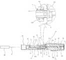
도 1은 본 발명의 바람직한 실시예에 따른 모드변환 기능이 있는 현장 조립형 광커넥터를 도시한 분해 사시도.
도 2는 도 1의 광접속 하우징을 도시한 사시도.
도 3은 도 1의 현장 조립 광커넥터에 페룰이 삽입되는 과정을 나타낸 단면도.
도 4는 도 1의 페룰을 도시한 단면도.
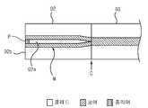
도 5는 도 4의 모드변환 광섬유를 확대하여 도시한 단면도.1 is an exploded perspective view showing a field-mounted optical connector with a mode conversion function according to a preferred embodiment of the present invention.
Fig. 2 is a perspective view showing the optical connecting housing of Fig. 1; Fig.
3 is a cross-sectional view illustrating a process in which a ferrule is inserted into the field assembly optical connector of FIG. 1.
4 is a sectional view of the ferrule of FIG.
FIG. 5 is an enlarged cross-sectional view of the mode conversion optical fiber of FIG. 4. FIG.
이하 첨부된 도면을 참조하면서 본 발명에 따른 바람직한 실시예를 상세히 설명하기로 한다. 이에 앞서, 본 명세서 및 청구범위에 사용된 용어나 단어는 통상적이거나 사전적인 의미로 한정해서 해석되어서는 아니 되며, 발명자는 그 자신의 발명을 가장 최선의 방법으로 설명하기 위해 용어의 개념을 적절하게 정의할 수 있다는 원칙에 입각하여, 본 발명의 기술적 사상에 부합하는 의미와 개념으로 해석되어야만 한다.Hereinafter, preferred embodiments of the present invention will be described in detail with reference to the accompanying drawings. Prior to this, terms and words used in the present specification and claims should not be construed as limited to ordinary or dictionary terms, and the inventor should appropriately interpret the concepts of the terms appropriately The present invention should be construed in accordance with the meaning and concept consistent with the technical idea of the present invention.
따라서, 본 명세서에 기재된 실시예와 도면에 도시된 구성은 본 발명의 가장 바람직한 일 실시예에 불과할 뿐이고 본 발명의 기술적 사상을 모두 대변하는 것은 아니므로, 본 출원시점에 있어서 이들을 대체할 수 있는 다양한 균등물과 변형예들이 있을 수 있음을 이해하여야 한다.
Therefore, the embodiments described in this specification and the configurations shown in the drawings are merely the most preferred embodiments of the present invention and do not represent all the technical ideas of the present invention. Therefore, It is to be understood that equivalents and modifications are possible.
도 1에 도시한 바와 같이, 본 발명의 바람직한 실시예에 따른 모드변환 기능이 있는 현장 조립형 광커넥터는 중심에 모드변환 광섬유(91)를 갖는 페룰(90)과 모드변환 광섬유(91)와 다른 광섬유를 접속하기 위한 커넥터를 포함한다.As shown in FIG. 1, the field-assembled optical connector having a mode conversion function according to the preferred embodiment of the present invention is different from the
본 실시예에서 커넥터는 커넥터 하우징(80), 플러그(10), 광접속 부재(30), 부트부 덮개(20), 스크류 캡(70)을 포함한다.In this embodiment, the connector includes a
커넥터 하우징(80)은 플러그(10)가 내측에 삽입됨에 따라 플러그(10)의 둘레를 덮어서 플러그(10) 내에 삽입된 후술할 광접속 부재(30)를 보호한다.The
플러그(10)는 커넥터 하우징(80) 내에 삽입되는 전방측에 수용부(11)가 형성되고, 수용부(11)의 후방측에는 플러그(10) 내측으로 삽입되는 광케이블(100)을 고정하기 위한 부트부(12)가 일체로 형성된다.The
수용부(11)는 후술할 광접속 부재(30)를 수용하기 위한 것으로, 도 3에 도시한 바와 같이 중앙 부위가 개방되어 내측에 수용되는 광접속 부재(30)가 외부에 노출되도록 하고, 부트부(12)측에 배치된 일측면에는 체결 구멍(11a)이 형성되어 있다. 그리고 수용부(11)의 좌, 우 측벽에는 후술할 부트부 덮개(20)의 체결을 위한 축 돌기(13)가 형성되어 있다.The
부트부(12)의 외주면에는 제1 나사부(12a)가 형성되어 있고, 내주면에는 내경을 따라 형성되어 돌출된 제1 링형 돌기(12b)들이 형성되어 있다. 여기서, 제1 링형 돌기(12b)는 부트부(12)의 내측에 삽입되는 광케이블(100)의 외부피복에 밀착되어 광케이블(100)을 가압한다.The first threaded
그리고 부트부(12)의 제1 링형 돌기(12b)들 후방측에는 광케이블(100)의 광섬유(101)가 삽입될 때 광섬유(101)를 가이드하는 광섬유 가이드홈(12c)이 형성되어 있다.The optical fiber guide groove 12c for guiding the optical fiber 101 when the optical fiber 101 of the optical cable 100 is inserted is formed on the rear side of the first ring-
부트부 덮개(20)는 후방측이 부트부(12)와 대응되는 형상으로 형성되고 외주면에 부트부(12)의 제1 나사부(12a)와 대응되는 제2 나사부(21)가 형성되고, 내주면에는 제1 링형 돌기(12b)들에 대응되는 제2 링형 돌기(22)들이 형성되어 있다. 그리고 전방측의 좌, 우에는 플러그(10)의 축 돌기(13)들에 체결되는 축 돌기 체결홈(23)이 형성된다.The
이러한 부트부 덮개(20)는 축 돌기(13)를 중심으로 상, 하로 회동되면서 플러그(10)의 부트부(12) 내측을 개폐하며, 부트부(12)와 함께 부트부(12)에 삽입된 광케이블(100)을 가압하여 고정한다.This
스크류 캡(70)은, 도 3에 도시한 바와 같이 부트부(12)와 부트부 덮개(20)에 형성된 제1 나사부(12a) 및 제2 나사부(21)에 나사 결합되어, 부트부 덮개(20)가 닫혀진 상태를 고정하면서 부트부(12) 및 부트부 덮개(20) 내에 삽입된 광케이블(100)이 가압되도록 하여 고정시킨다. 그리고 스크류 캡(70)의 단부에는 광케이블(100)이 삽입되기 위한 구멍(71)이 형성되어 있다.The
광접속 부재(30)는 플러그(10) 내부에 삽입되어 페룰(90)의 모드변환 광섬유(91)와 광케이블(100)의 광섬유(101)를 접속시키기 위한 것으로, 도 1에 도시한 바와 같이 광접속 하우징(41), 광접속 하우징 덮개(51), 광접속 하우징 홀더(61)로 구성된다.The
광접속 하우징(41)은 전방측에 페룰(90)이 삽입되어 고정되는 페룰 삽입부(42)가 형성되고, 후방측에는 광케이블(100)의 광섬유(101)가 삽입되는 광섬유 삽입부(43)가 형성된다. 그리고 페룰 삽입부(42)와 광섬유 삽입부(43) 사이에는 페룰(90)의 모드변환 광섬유(91) 및 광케이블(100)의 광섬유(101)가 안착되어 상호 접속되는 광섬유 접속홈(44a)을 가진 상측이 개방된 광섬유 접속부(44)가 일체로 형성된다.The
또한 광섬유 삽입부(43)의 단부에는 플러그(10)의 체결 구멍(11a)에 체결되어 광접속 하우징(41)을 플러그(10)의 수용부(11) 내에 고정하기 위한 단부측으로 테이퍼진 환형 돌부(43a)가 형성된다.The end of the optical
여기서, 환형 돌부(43a)는 체결 구멍(11a)에 체결된 상태에서 부트부(12) 내측에 노출되어 부트부(12)에 형성된 광섬유 가이드홈(12c)과 마주하며, 일단은 광섬유 접속부(44)의 끝단에 지지되고 다른 일단은 체결 구멍(11a)이 형성된 측의 플러그(10)의 내벽(10a)에 지지되고 광접속 하우징(41)이 플러그(10) 내에서 유동되는 것을 방지하기 위한 스프링(S)이 광섬유 삽입부(43) 둘레에 체결되어 있다.The annular protruding
그리고 광섬유 삽입부(43)의 외주면 둘레에는, 도 2와 같이 페룰 삽입부(42)로 페룰(90)을 삽입하는 과정에서 강제로 눌리면서 이동되는, 즉 페룰(90)을 페룰 삽입부(42)로 삽입하기 위해 페룰(90)이 눌릴 때 광접속 하우징(41)이 부트부(12)측으로 이동되는 범위를 제한하기 위한 스톱퍼(43b)가 형성되어 있다. 스톱퍼(43b)는 페룰(90)이 눌려서 광접속 하우징(41)이 부트부(12)측으로 이동될 때 플러그(10)의 내벽(10a)에 지지된다.2, the
또한 광섬유 접속부(44)에 형성된 광섬유 접속홈(44a)의 좌측 및 우측에 광섬유 접속홈(44a)의 길이 방향을 따라 길게 형성되어 광섬유 접속홈(44a)의 상층에 위치하며, 광섬유 접속홈(44a) 내에서 접속되는 두 광섬유(91, 101)가 접속 될 때 광섬유 접속홈(44a) 내에서 이탈되는 매칭젤(J)을 수용하기 위한 매칭젤 수용홈(44c)이 형성되어 있다.In addition, the left and right sides of the optical
여기서, 매칭젤(J)은 서로 다른 단면 형상을 갖는 광접속되는 두 광섬유의 반사/삽입 손실이 방지되도록 두 광섬유(91, 101)를 정확히 접속시키기 위하여 사용되며, 광섬유 접속홈(44a) 내에 미리 충진되는 재료이다.Here, the matching gel (J) is used to accurately connect the two optical fibers (91, 101) to prevent the reflection / insertion loss of the two optically connected optical fibers having a different cross-sectional shape, in advance in the optical fiber connection groove (44a) The material to be filled.
광접속 하우징 덮개(51)는 광섬유 접속부(44) 상측에서 체결되어 광섬유 접속부(44)를 덮으며, 광섬유 접속홈(44a) 내에서 접속된 광섬유(91, 101)들을 가압하여 광섬유(91, 101)들의 이탈을 방지한다. 그리고 광접속 하우징 덮개(51)의 상면 일측에는 상향 돌출되어 길이 방향을 따라 형성된 돌출부(53)가 형성된다.The optical
여기서, 광접속 하우징(41)의 광섬유 접속부(44)의 좌, 우측 단부에는 체결홈(44b)이 형성되고, 광접속 하우징 덮개(51)의 좌, 우측 단부에는 체결홈(44b)에 대응되는 위치에 체결 돌기(52)가 형성된다. 이에 따라, 광접속 하우징(41) 및 광접속 하우징 덮개(51)는 체결홈(44b) 및 체결 돌기(52)들에 의해 체결된다.A
또한 광섬유 접속부(44) 및 광접속 하우징 덮개(51)에는 제1 가이드홈(45) 및 제2 가이드홈(54)이 형성된다.In addition, the
제1 가이드홈(45)은 광섬유 접속홈(44a) 양측에 광섬유 접속홈(44a)을 향하여 경사지게 형성되어 광섬유 접속부(44) 내측으로 진입되는 광섬유(91, 101)들을 광섬유 접속홈(44a)으로 안내한다.The
제2 가이드홈(54)은 광접속 하우징 덮개(51) 양단에서 광섬유 접속홈(44a)측을 향하여 경사지게 형성되어 제1가이드홈(45)과 함께 광섬유(91, 101)들을 광섬유 접속홈(44a)으로 안내한다.The
광접속 하우징 홀더(60)는 광접속 하우징(41) 및 광접속 하우징 덮개(51)가 내측으로 삽입됨에 따라 내주면이 광접속 하우징(41) 및 광접속 하우징 덮개(51)를 감싸도록 체결되어 광접속 하우징 덮개(51)를 가압한다.The optical connection housing holder 60 is constructed such that the
이때, 광접속 하우징 홀더(60)의 내면 상측은 광접속 하우징 덮개(51)의 돌출부(53)에 접촉되어 돌출부(53)를 눌러서 광접속 하우징 덮개(51)를 가압한다.At this time, the upper side of the inner surface of the optical connection housing holder 60 contacts the
그리고 돌출부(53)에 접촉되는 내면 상측이 전진 방향, 즉 광접속 하우징(41)의 페룰 삽입부(42)측으로 전진되는 방향을 향하여 상향 경사지게 형성된다. 이에 따라, 광접속 하우징(41) 전방측으로 전진될 때 내면 상측이 돌출부(53)를 누르며, 후방측으로 후진될 때 돌출부(53)로부터 내면 상측이 이격된다.The upper side of the inner surface contacting the projecting
미설명 부호 C는 페룰(90)을 보호하는 페룰 보호용 캡이다.Reference character C denotes a ferrule protection cap for protecting the
페룰(90)은, 도 4에 도시한 바와 같이 중심에 모드변환 광섬유(91)를 갖는다.The
이렇게, 페룰(90) 내부에 삽입된 모드변환 광섬유(91)는 단일모드 광섬유(SMF; Single-Mode Fiber, 93)와 중공 광섬유(HOF; Hollow Optical Fiber, 92)가 융착 접속되어 있다.Thus, in the mode conversion
단일모드 광섬유(93)는 광 막대봉인 코어를 클래딩으로 코팅된 형태로 구성되며, 코어와 클래딩은 서로 다른 광 특성을 갖는다.The single mode
중공 광섬유(92)는, 적어도 일단이 중공 광섬유(92)의 코어 보다 굴절율이 낮은 폴리머에 의해 막혀있다.At least one end of the hollow
본 실시예에서 중공 광섬유(92)는, 도 5에 도시한 바와 같이 일단은 폐쇄되어 단일모드 광섬유(93)와 융착 접속되어 있고, 타단(92b)으로 개방된 구멍(92a)을 가진다.In this embodiment, as shown in Fig. 5, the hollow
구멍(92a)은 직경이 중공 광섬유(92)의 타단(92b)으로 갈수록 점차 증가하다가 모드변환구간(M)에서 일정하도록 형성되어 있다.The
즉, 중공 광섬유(92)는 서로 다른 광특성을 가지는 코어와 클래딩으로 구성되는데, 구멍(92a)의 형상과 동일하게 구멍(92a)의 외측에 코어가 형성되어 있다.That is, the hollow
상기와 같이 구성되는 중공 광섬유(92)는, 도 4에 도시한 바와 같이 중공 광섬유(92)의 폐쇄된 일단과 단일모드 광섬유(93)의 일단이 접속하는 접속구간(C)은 페룰(90)의 내부에 위치한다.As shown in FIG. 4, in the hollow
중공 광섬유(92)의 타단은 페룰(90)의 외부에 위치하고, 특히, 구멍(92a)의 직경이 일정하게 형성되는 모드변환구간(M)은 페룰(90)의 외부에 위치한다.The other end of the hollow
상기와 같이 구성된 중공 광섬유(92)의 구멍(92a)에는, 도 5에 도시한 바와 같이 중공 광섬유(92)의 코어 보다 굴절율이 낮은 폴리머(P)가 삽입되어 있다.In the
특히, 폴리머는 중공 광섬유(92)의 구멍(92a)의 단면이 폐쇄되도록 구멍(92a)의 일부인 입구측에만 채워지는 것이 바람직하다.In particular, the polymer is preferably filled only at the inlet side which is a part of the
또한, 굴절율이 낮은 액체상태의 폴리머가 광섬유(92)의 타단에 도포되어 자외선(UV)에 의해 경화된 상태이다.In addition, a liquid polymer having a low refractive index is applied to the other end of the
이렇게, 중공 광섬유(92)의 구멍(92a)에 굴절율이 낮은 폴리머(P)가 삽입되면, 빛이 스넬의 법칙에 의해서 굴절율이 높은 쪽으로 굴절되기 때문에 중공 광섬유(92)의 신호를 그대로 도넛 모양으로 진행되도록 할 수 있다.
In this way, when the polymer P having a low refractive index is inserted into the
상기와 같이 구성되는 본 발명의 바람직한 실시예에 따른 현장 조립형 커넥터의 광섬유 접속과정은 본 출원인이 기출원한 대한민국 등록특허 제114289호에 상세히 기재되어 있으므로 상기 공보를 참조하기로 하며, 여기에서는 광섬유 접속과정의 상세한 설명을 생략하기로 한다.The optical fiber connection process of the field assembly type connector according to the preferred embodiment of the present invention described above is described in detail in Korean Patent Registration No. 114289 filed by the applicant of the present application, A detailed description of the connection procedure will be omitted.
다만, 본 실시예에서는 페룰(9)의 외측으로 배치되는 모드변환 광섬유(91)는 단일모드 광섬유(93)로서, 플러그(10)의 부트부(12)에 고정되는 광케이블(100)의 단일모드 광섬유(110)와 동일한 모드 특성을 가지며, 플러그(10) 내에서 모드변환 광섬유(91)와 단일모드 광섬유(93)는 접속이 이루어진다.
However, in the present embodiment, the mode conversion
이하, 상기와 같이 구성된 본 발명의 바람직한 실시예에 따른 모드변환 광섬유 제조방법을 설명하면 다음과 같다.Hereinafter, a mode conversion optical fiber manufacturing method according to a preferred embodiment of the present invention configured as described above are as follows.
먼저, 중공 광섬유(92)의 폐쇄된 타단에 단일모드 광섬유(93)를 융착 접속한다. (S0 단계)First, the single mode
다음으로, 중공 광섬유(92)의 일단으로 개방되어 형성된 구멍(92a)에 중공 광섬유(92)의 코어 보다 굴절율이 낮은 폴리머가 삽입되도록 한다. (S1 단계) 즉, 중공 광섬유(92)의 구멍(92a)이 형성된 단면에 액체상태의 폴리머를 도포하면 폴리머가 구멍(92a)으로 흘러들어가면서 삽입된다.Next, a polymer having a refractive index lower than that of the core of the hollow
다음으로, 액체상태의 폴리머를 자외선(UV) 등을 이용하여 경화시킨다. (S2 단계)Next, the polymer in the liquid state is cured using ultraviolet (UV) or the like. (S2 step)
이와 같이, 굴절율이 낮은 폴리머의 경화 후 융착 접속된 단일모드 광섬유(93)와 중공 광섬유(92)를 페룰(90)의 구멍에 삽입한다.In this manner, the single mode
이후, 중공 광섬유(92)를 감싸는 페룰(90)의 구멍 외측에 배치되어 중공 광섬유(92)를 고정하고 있는 잔여 에폭시를 연마하여 물리적으로 제거할 수 있다. 에폭시를 연마하는 방법은 광 패치코드 연마기술을 이용하며, 이는 종래에 이용되는 기술이므로 상세한 설명을 생략하기로 한다. 잔여 에폭시를 제거하는 다른 방법으로, 잔여 에폭시를 화학처리하여 화학적으로 제거할 수 있다.
Thereafter, the remaining epoxy that is disposed outside the hole of the
상기와 같은 방법으로 제작되는 모드변환 광섬유는 종래의 MMF-HOF-SMF방식에서 MMF 부분이 HOF에 폴리머를 삽입하는 방법으로 대체되어 모드변환이 이루어지므로 중공 광섬유(92)와 단일모드 광섬유(93)의 접속구간에 대한 길이만 필요로 하므로 모드변환구간의 길이가 10mm 이내로 제조될 수 있다. 따라서, 모드변환 광섬유의 전체길이가 16mm 이내로 제조될 수 있다.Since the mode conversion optical fiber manufactured by the above method is replaced by the method of inserting the polymer into the HOF in the MMF-HOF-SMF method, the hollow
또한, 중공 광섬유(92)와 단일모드 광섬유(93)가 융착된 부분이 페룰(90)의 내부에 위치하기 때문에 외부의 충격 및 삽입되는 광케이블의 광섬유 압력에 의한 모드변환 광섬유의 파손을 방지할 수 있다.In addition, since the portion in which the hollow
나아가, 이물질에 의한 빛의 굴절 영향을 받지 않도록 하기 위하여 중공 광섬유(92) 내에 이물질이 들어가지 않도록 제작하고 도넛 모양의 중공 광섬유(92)의 특성을 살려 제작함으로써, 모드변환 광섬유의 광학적인 특성을 살리면서도 제작이 매우 용이하다.
Furthermore, in order not to be affected by the refraction of light caused by foreign matter, the optical fiber of the mode-converted optical fiber is manufactured by making the foreign material not enter the hollow
이상과 같이, 본 발명은 비록 한정된 실시예와 도면에 의해 설명되었으나, 본 발명은 이것에 의해 한정되지 않으며 본 발명이 속하는 기술분야에서 통상의 지식을 가진 자에 의해 본 발명의 기술 사상과 아래에 기재될 청구범위의 균등 범위 내에서 다양한 수정 및 변형 가능함은 물론이다.While the present invention has been particularly shown and described with reference to exemplary embodiments thereof, it is to be understood that the invention is not limited to the disclosed exemplary embodiments. It is to be understood that various changes and modifications may be made without departing from the scope of the appended claims.
10 : 플러그 11 : 수용부
12 : 부트부 12a : 제1 나사부
12b : 제1 링형 돌기 12c : 광섬유 가이드홈
13 : 축 돌기 20 : 부트부 덮개
21 : 제1 나사부 22 : 제2 링형 돌기
23 : 축 돌기 체결홈 30 : 광접속 부재
41 : 광접속 하우징42 : 페룰 삽입부
43 : 광섬유 삽입부43a : 환형 돌부
43b : 스톱퍼44 : 광섬유 접속부
44a : 광섬유 접속홈44b : 체결홈
44c : 매칭젤 수용홈45 : 제1 가이드홈
51 : 광접속 하우징 덮개52 : 체결 돌기
53 : 돌출부54 : 제2 가이드홈
61 : 광접속 하우징 홀더70 : 스크류 캡
80 : 커넥터 하우징90 : 페룰
91 : 모드변환 광섬유92 : 중공 광섬유
93 : 단일모드 광섬유10: plug 11: receptacle
12:
12b: first ring-shaped
13: Axial projection 20: Boot cover
21: first screw portion 22: second ring-shaped projection
23: shaft projection locking groove 30: optical connecting member
41: optical connection housing 42: ferrule insertion part
43: optical
43b: stopper 44: optical fiber connector
44a: optical
44c: matching gel receiving groove 45: first guide groove
51: optical connection housing cover 52: fastening projection
53: protrusion 54: second guide groove
61
80: connector housing 90: ferrule
91: mode conversion fiber 92: hollow fiber
93: single mode fiber
Claims (7)
Translated fromKorean상기 모드변환 광섬유와 다른 광섬유를 접속하기 위한 커넥터;를 포함하되,
상기 모드변환 광섬유는 단일모드 광섬유(SMF)와 중공 광섬유(HOF)가 융착 접속되어 있고,
상기 중공 광섬유는,
일단이 폐쇄되어 상기 단일모드 광섬유와 접속되어 있고,
타단으로 개방된 구멍을 가지되, 상기 구멍의 입구측에 상기 중공 광섬유의 코어 보다 굴절율이 낮은 폴리머에 의해 끝단이 막혀있는 것을 특징으로 하는 모드변환 기능이 있는 현장 조립형 광커넥터.Ferrule having a mode conversion optical fiber in the center; And
Including; connector for connecting the mode conversion optical fiber and another optical fiber,
The mode conversion optical fiber is a single mode optical fiber (SMF) and a hollow fiber (HOF) is fusion-spliced,
The hollow optical fiber,
One end is closed and connected to the single mode optical fiber,
The field assembly type optical connector having a mode conversion function, characterized in that it has a hole opened to the other end, the end of the hole is blocked by a polymer having a lower refractive index than the core of the hollow optical fiber.
상기 단일모드 광섬유의 일단과 상기 중공 광섬유의 일단이 접속하는 접속구간은 상기 페룰 내부에 위치하고,
상기 중공 광섬유의 타단은 상기 페룰 외부에 위치하는 것을 특징으로 하는 모드변환 기능이 있는 현장 조립형 광커넥터.The method of claim 1,
A connection section between one end of the single mode optical fiber and one end of the hollow optical fiber is located inside the ferrule,
The other end of the hollow optical fiber is a field assembly type optical connector having a mode conversion function, characterized in that located outside the ferrule.
상기 구멍은 직경이 상기 중공 광섬유의 타단으로 갈수록 점차 증가하다가 모드변환구간에서 일정하도록 형성되어 있고,
상기 모드변환구간은 상기 페룰의 외부에 위치하는 것을 특징으로 하는 모드변환 기능이 있는 현장 조립형 광커넥터.3. The method according to claim 1 or 2,
The hole is formed so that the diameter gradually increases toward the other end of the hollow optical fiber and is constant in the mode conversion section.
The mode conversion section is a field assembly type optical connector with a mode conversion function, characterized in that located on the outside of the ferrule.
상기 굴절율이 낮은 폴리머는, 액체상태의 폴리머가 상기 중공 광섬유의 타단에 도포된 후 경화된 것을 특징으로 하는 모드변환 기능이 있는 현장 조립형 광커넥터.3. The method according to claim 1 or 2,
The polymer having a low refractive index is a field-assembled optical connector with a mode conversion function, characterized in that the polymer in the liquid state is applied to the other end of the hollow optical fiber and cured.
Priority Applications (1)
| Application Number | Priority Date | Filing Date | Title |
|---|---|---|---|
| KR1020120105324AKR101377438B1 (en) | 2012-09-21 | 2012-09-21 | Optical connector for assembling in the field having mode conversion function and manufacturing method for optical fiber having mode conversion function |
Applications Claiming Priority (1)
| Application Number | Priority Date | Filing Date | Title |
|---|---|---|---|
| KR1020120105324AKR101377438B1 (en) | 2012-09-21 | 2012-09-21 | Optical connector for assembling in the field having mode conversion function and manufacturing method for optical fiber having mode conversion function |
Publications (1)
| Publication Number | Publication Date |
|---|---|
| KR101377438B1true KR101377438B1 (en) | 2014-03-25 |
Family
ID=50649389
Family Applications (1)
| Application Number | Title | Priority Date | Filing Date |
|---|---|---|---|
| KR1020120105324AExpired - Fee RelatedKR101377438B1 (en) | 2012-09-21 | 2012-09-21 | Optical connector for assembling in the field having mode conversion function and manufacturing method for optical fiber having mode conversion function |
Country Status (1)
| Country | Link |
|---|---|
| KR (1) | KR101377438B1 (en) |
Cited By (3)
| Publication number | Priority date | Publication date | Assignee | Title |
|---|---|---|---|---|
| WO2018213088A1 (en)* | 2017-05-18 | 2018-11-22 | Corning Research & Development Corporation | Fiber optic connector with polymeric material between fiber end and ferrule end, and fabrication method |
| CN110412687A (en)* | 2019-07-12 | 2019-11-05 | 华中科技大学鄂州工业技术研究院 | Structure and preparation method for coupling from large-diameter hollow-core fiber to single-mode fiber |
| WO2020070487A1 (en)* | 2018-10-03 | 2020-04-09 | Lumenisity Limited | Optical waveguide adapter assembly |
Citations (1)
| Publication number | Priority date | Publication date | Assignee | Title |
|---|---|---|---|---|
| KR101114289B1 (en)* | 2010-12-06 | 2012-03-05 | 주식회사 에이제이월드 | Optical connector for assembling in the field |
- 2012
- 2012-09-21KRKR1020120105324Apatent/KR101377438B1/ennot_activeExpired - Fee Related
Patent Citations (1)
| Publication number | Priority date | Publication date | Assignee | Title |
|---|---|---|---|---|
| KR101114289B1 (en)* | 2010-12-06 | 2012-03-05 | 주식회사 에이제이월드 | Optical connector for assembling in the field |
Cited By (6)
| Publication number | Priority date | Publication date | Assignee | Title |
|---|---|---|---|---|
| WO2018213088A1 (en)* | 2017-05-18 | 2018-11-22 | Corning Research & Development Corporation | Fiber optic connector with polymeric material between fiber end and ferrule end, and fabrication method |
| US11249256B2 (en) | 2017-05-18 | 2022-02-15 | Corning Research & Development Corporation | Fiber optic connector with polymeric material between fiber end and ferrule end, and fabrication method |
| WO2020070487A1 (en)* | 2018-10-03 | 2020-04-09 | Lumenisity Limited | Optical waveguide adapter assembly |
| US11960119B2 (en) | 2018-10-03 | 2024-04-16 | Microsoft Technology Licensing, Llc | Optical waveguide adapter assembly |
| CN110412687A (en)* | 2019-07-12 | 2019-11-05 | 华中科技大学鄂州工业技术研究院 | Structure and preparation method for coupling from large-diameter hollow-core fiber to single-mode fiber |
| CN110412687B (en)* | 2019-07-12 | 2020-10-27 | 华中科技大学鄂州工业技术研究院 | Structure and preparation method of coupling from large-core diameter hollow-core fiber to single-mode fiber |
Similar Documents
| Publication | Publication Date | Title |
|---|---|---|
| US12405430B2 (en) | Fiber optic connector | |
| KR101114289B1 (en) | Optical connector for assembling in the field | |
| KR101105664B1 (en) | Field Assembly Optical Connectors | |
| US8801301B2 (en) | Simplex connectors for multicore optical fiber cables | |
| AU619117B2 (en) | Optical fiber splicing device | |
| US8272792B2 (en) | Retention bodies for fiber optic cable assemblies | |
| CN102171598B (en) | Fan-out line cable assembly and method | |
| US6702478B2 (en) | Optical fiber connector | |
| EP2340452B1 (en) | Retention bodies for fiber optic cable assemblies | |
| US20070196053A1 (en) | Isolated Fiber Optic Union Adapters | |
| CN101501544A (en) | Reinforced Fiber Optic Connector Assemblies | |
| JP2010191420A (en) | Single-piece cable retention housing for hardened outside plant connector | |
| US8285096B2 (en) | Fiber optic cable assemblies and securing methods | |
| US20080175540A1 (en) | Optical Connector Suitable for Field Assembly | |
| US20120315001A1 (en) | Fiber optic connector potting method | |
| US20210389528A1 (en) | Optical connector ferrule, sleeve, and method for manufacturing ferrule member | |
| Kawasaki et al. | Four-fiber fan-out for MCF with square lattice structure | |
| CA1311349C (en) | Method of splicing fibers | |
| KR101377438B1 (en) | Optical connector for assembling in the field having mode conversion function and manufacturing method for optical fiber having mode conversion function | |
| US8303193B2 (en) | Retention bodies for fiber optic cable assemblies | |
| KR100821298B1 (en) | Field-assembled optical connector with improved fiber fixing | |
| CN112051645A (en) | a fiber optic connector | |
| KR101041953B1 (en) | Optical connector for assembling in the field | |
| KR20180013143A (en) | Optical connector | |
| KR101440580B1 (en) | Optical connector having filtering function |
Legal Events
| Date | Code | Title | Description |
|---|---|---|---|
| A201 | Request for examination | ||
| PA0109 | Patent application | St.27 status event code:A-0-1-A10-A12-nap-PA0109 | |
| PA0201 | Request for examination | St.27 status event code:A-1-2-D10-D11-exm-PA0201 | |
| D13-X000 | Search requested | St.27 status event code:A-1-2-D10-D13-srh-X000 | |
| D14-X000 | Search report completed | St.27 status event code:A-1-2-D10-D14-srh-X000 | |
| E902 | Notification of reason for refusal | ||
| PE0902 | Notice of grounds for rejection | St.27 status event code:A-1-2-D10-D21-exm-PE0902 | |
| E13-X000 | Pre-grant limitation requested | St.27 status event code:A-2-3-E10-E13-lim-X000 | |
| P11-X000 | Amendment of application requested | St.27 status event code:A-2-2-P10-P11-nap-X000 | |
| P13-X000 | Application amended | St.27 status event code:A-2-2-P10-P13-nap-X000 | |
| E701 | Decision to grant or registration of patent right | ||
| PE0701 | Decision of registration | St.27 status event code:A-1-2-D10-D22-exm-PE0701 | |
| GRNT | Written decision to grant | ||
| PR0701 | Registration of establishment | St.27 status event code:A-2-4-F10-F11-exm-PR0701 | |
| PR1002 | Payment of registration fee | Fee payment year number:1 St.27 status event code:A-2-2-U10-U11-oth-PR1002 | |
| PG1601 | Publication of registration | St.27 status event code:A-4-4-Q10-Q13-nap-PG1601 | |
| PN2301 | Change of applicant | St.27 status event code:A-5-5-R10-R11-asn-PN2301 St.27 status event code:A-5-5-R10-R13-asn-PN2301 | |
| P22-X000 | Classification modified | St.27 status event code:A-4-4-P10-P22-nap-X000 | |
| PN2301 | Change of applicant | St.27 status event code:A-5-5-R10-R11-asn-PN2301 St.27 status event code:A-5-5-R10-R13-asn-PN2301 | |
| FPAY | Annual fee payment | Payment date:20170227 Year of fee payment:6 | |
| PR1001 | Payment of annual fee | Fee payment year number:4 St.27 status event code:A-4-4-U10-U11-oth-PR1001 | |
| PN2301 | Change of applicant | St.27 status event code:A-5-5-R10-R11-asn-PN2301 St.27 status event code:A-5-5-R10-R13-asn-PN2301 | |
| FPAY | Annual fee payment | Payment date:20200303 Year of fee payment:7 | |
| PR1001 | Payment of annual fee | Fee payment year number:7 St.27 status event code:A-4-4-U10-U11-oth-PR1001 | |
| R17-X000 | Change to representative recorded | St.27 status event code:A-5-5-R10-R17-oth-X000 | |
| PR1001 | Payment of annual fee | Fee payment year number:8 St.27 status event code:A-4-4-U10-U11-oth-PR1001 | |
| R18-X000 | Changes to party contact information recorded | St.27 status event code:A-5-5-R10-R18-oth-X000 | |
| PN2301 | Change of applicant | St.27 status event code:A-5-5-R10-R11-asn-PN2301 St.27 status event code:A-5-5-R10-R13-asn-PN2301 | |
| PR1001 | Payment of annual fee | Fee payment year number:9 St.27 status event code:A-4-4-U10-U11-oth-PR1001 | |
| PC1903 | Unpaid annual fee | Not in force date:20230319 Payment event data comment text:Termination Category : DEFAULT_OF_REGISTRATION_FEE St.27 status event code:A-4-4-U10-U13-oth-PC1903 | |
| PC1903 | Unpaid annual fee | Ip right cessation event data comment text:Termination Category : DEFAULT_OF_REGISTRATION_FEE Not in force date:20230319 St.27 status event code:N-4-6-H10-H13-oth-PC1903 | |
| P22-X000 | Classification modified | St.27 status event code:A-4-4-P10-P22-nap-X000 |