KR101375742B1 - Apparatus for processing substrate - Google Patents
Apparatus for processing substrateDownload PDFInfo
- Publication number
- KR101375742B1 KR101375742B1KR1020120148665AKR20120148665AKR101375742B1KR 101375742 B1KR101375742 B1KR 101375742B1KR 1020120148665 AKR1020120148665 AKR 1020120148665AKR 20120148665 AKR20120148665 AKR 20120148665AKR 101375742 B1KR101375742 B1KR 101375742B1
- Authority
- KR
- South Korea
- Prior art keywords
- heater
- gas
- substrate
- cooling ring
- outside
- Prior art date
- Legal status (The legal status is an assumption and is not a legal conclusion. Google has not performed a legal analysis and makes no representation as to the accuracy of the status listed.)
- Active
Links
- 239000000758substrateSubstances0.000titleclaimsabstractdescription64
- 238000000034methodMethods0.000claimsabstractdescription51
- 238000001816coolingMethods0.000claimsabstractdescription50
- 238000010438heat treatmentMethods0.000claimsabstractdescription13
- 239000003507refrigerantSubstances0.000claimsdescription29
- 238000007599dischargingMethods0.000claimsdescription4
- 239000002826coolantSubstances0.000abstractdescription11
- 239000007789gasSubstances0.000description82
- 238000003860storageMethods0.000description5
- 238000005137deposition processMethods0.000description4
- 238000000151depositionMethods0.000description3
- 239000011261inert gasSubstances0.000description3
- 239000002184metalSubstances0.000description3
- 239000000203mixtureSubstances0.000description3
- 239000004065semiconductorSubstances0.000description3
- XUIMIQQOPSSXEZ-UHFFFAOYSA-NSiliconChemical compound[Si]XUIMIQQOPSSXEZ-UHFFFAOYSA-N0.000description2
- 238000006243chemical reactionMethods0.000description2
- 239000007795chemical reaction productSubstances0.000description2
- 230000008021depositionEffects0.000description2
- 238000009792diffusion processMethods0.000description2
- 229910052710siliconInorganic materials0.000description2
- 239000010703siliconSubstances0.000description2
- 229910018072Al 2 O 3Inorganic materials0.000description1
- IJGRMHOSHXDMSA-UHFFFAOYSA-NAtomic nitrogenChemical compoundN#NIJGRMHOSHXDMSA-UHFFFAOYSA-N0.000description1
- XYFCBTPGUUZFHI-UHFFFAOYSA-NPhosphineChemical compoundPXYFCBTPGUUZFHI-UHFFFAOYSA-N0.000description1
- BLRPTPMANUNPDV-UHFFFAOYSA-NSilaneChemical compound[SiH4]BLRPTPMANUNPDV-UHFFFAOYSA-N0.000description1
- 238000005229chemical vapour depositionMethods0.000description1
- 238000011109contaminationMethods0.000description1
- 230000007547defectEffects0.000description1
- 230000006866deteriorationEffects0.000description1
- ZOCHARZZJNPSEU-UHFFFAOYSA-NdiboronChemical compoundB#BZOCHARZZJNPSEU-UHFFFAOYSA-N0.000description1
- BUMGIEFFCMBQDG-UHFFFAOYSA-NdichlorosiliconChemical compoundCl[Si]ClBUMGIEFFCMBQDG-UHFFFAOYSA-N0.000description1
- 239000006185dispersionSubstances0.000description1
- 238000009826distributionMethods0.000description1
- 239000002019doping agentSubstances0.000description1
- 239000001257hydrogenSubstances0.000description1
- 229910052739hydrogenInorganic materials0.000description1
- 125000004435hydrogen atomChemical class[H]*0.000description1
- 238000004519manufacturing processMethods0.000description1
- 239000000463materialSubstances0.000description1
- 239000002243precursorSubstances0.000description1
- 239000000047productSubstances0.000description1
- 239000011819refractory materialSubstances0.000description1
- 238000007789sealingMethods0.000description1
- 229910000077silaneInorganic materials0.000description1
Images


Classifications
- H01L21/205—
- C—CHEMISTRY; METALLURGY
- C23—COATING METALLIC MATERIAL; COATING MATERIAL WITH METALLIC MATERIAL; CHEMICAL SURFACE TREATMENT; DIFFUSION TREATMENT OF METALLIC MATERIAL; COATING BY VACUUM EVAPORATION, BY SPUTTERING, BY ION IMPLANTATION OR BY CHEMICAL VAPOUR DEPOSITION, IN GENERAL; INHIBITING CORROSION OF METALLIC MATERIAL OR INCRUSTATION IN GENERAL
- C23C—COATING METALLIC MATERIAL; COATING MATERIAL WITH METALLIC MATERIAL; SURFACE TREATMENT OF METALLIC MATERIAL BY DIFFUSION INTO THE SURFACE, BY CHEMICAL CONVERSION OR SUBSTITUTION; COATING BY VACUUM EVAPORATION, BY SPUTTERING, BY ION IMPLANTATION OR BY CHEMICAL VAPOUR DEPOSITION, IN GENERAL
- C23C16/00—Chemical coating by decomposition of gaseous compounds, without leaving reaction products of surface material in the coating, i.e. chemical vapour deposition [CVD] processes
- C23C16/44—Chemical coating by decomposition of gaseous compounds, without leaving reaction products of surface material in the coating, i.e. chemical vapour deposition [CVD] processes characterised by the method of coating
- C23C16/46—Chemical coating by decomposition of gaseous compounds, without leaving reaction products of surface material in the coating, i.e. chemical vapour deposition [CVD] processes characterised by the method of coating characterised by the method used for heating the substrate
- C—CHEMISTRY; METALLURGY
- C23—COATING METALLIC MATERIAL; COATING MATERIAL WITH METALLIC MATERIAL; CHEMICAL SURFACE TREATMENT; DIFFUSION TREATMENT OF METALLIC MATERIAL; COATING BY VACUUM EVAPORATION, BY SPUTTERING, BY ION IMPLANTATION OR BY CHEMICAL VAPOUR DEPOSITION, IN GENERAL; INHIBITING CORROSION OF METALLIC MATERIAL OR INCRUSTATION IN GENERAL
- C23C—COATING METALLIC MATERIAL; COATING MATERIAL WITH METALLIC MATERIAL; SURFACE TREATMENT OF METALLIC MATERIAL BY DIFFUSION INTO THE SURFACE, BY CHEMICAL CONVERSION OR SUBSTITUTION; COATING BY VACUUM EVAPORATION, BY SPUTTERING, BY ION IMPLANTATION OR BY CHEMICAL VAPOUR DEPOSITION, IN GENERAL
- C23C16/00—Chemical coating by decomposition of gaseous compounds, without leaving reaction products of surface material in the coating, i.e. chemical vapour deposition [CVD] processes
- C23C16/44—Chemical coating by decomposition of gaseous compounds, without leaving reaction products of surface material in the coating, i.e. chemical vapour deposition [CVD] processes characterised by the method of coating
- C23C16/4412—Details relating to the exhausts, e.g. pumps, filters, scrubbers, particle traps
- C—CHEMISTRY; METALLURGY
- C23—COATING METALLIC MATERIAL; COATING MATERIAL WITH METALLIC MATERIAL; CHEMICAL SURFACE TREATMENT; DIFFUSION TREATMENT OF METALLIC MATERIAL; COATING BY VACUUM EVAPORATION, BY SPUTTERING, BY ION IMPLANTATION OR BY CHEMICAL VAPOUR DEPOSITION, IN GENERAL; INHIBITING CORROSION OF METALLIC MATERIAL OR INCRUSTATION IN GENERAL
- C23C—COATING METALLIC MATERIAL; COATING MATERIAL WITH METALLIC MATERIAL; SURFACE TREATMENT OF METALLIC MATERIAL BY DIFFUSION INTO THE SURFACE, BY CHEMICAL CONVERSION OR SUBSTITUTION; COATING BY VACUUM EVAPORATION, BY SPUTTERING, BY ION IMPLANTATION OR BY CHEMICAL VAPOUR DEPOSITION, IN GENERAL
- C23C16/00—Chemical coating by decomposition of gaseous compounds, without leaving reaction products of surface material in the coating, i.e. chemical vapour deposition [CVD] processes
- C23C16/44—Chemical coating by decomposition of gaseous compounds, without leaving reaction products of surface material in the coating, i.e. chemical vapour deposition [CVD] processes characterised by the method of coating
- C23C16/458—Chemical coating by decomposition of gaseous compounds, without leaving reaction products of surface material in the coating, i.e. chemical vapour deposition [CVD] processes characterised by the method of coating characterised by the method used for supporting substrates in the reaction chamber
- C23C16/4582—Rigid and flat substrates, e.g. plates or discs
- C23C16/4583—Rigid and flat substrates, e.g. plates or discs the substrate being supported substantially horizontally
- C23C16/4585—Devices at or outside the perimeter of the substrate support, e.g. clamping rings, shrouds
- C—CHEMISTRY; METALLURGY
- C23—COATING METALLIC MATERIAL; COATING MATERIAL WITH METALLIC MATERIAL; CHEMICAL SURFACE TREATMENT; DIFFUSION TREATMENT OF METALLIC MATERIAL; COATING BY VACUUM EVAPORATION, BY SPUTTERING, BY ION IMPLANTATION OR BY CHEMICAL VAPOUR DEPOSITION, IN GENERAL; INHIBITING CORROSION OF METALLIC MATERIAL OR INCRUSTATION IN GENERAL
- C23C—COATING METALLIC MATERIAL; COATING MATERIAL WITH METALLIC MATERIAL; SURFACE TREATMENT OF METALLIC MATERIAL BY DIFFUSION INTO THE SURFACE, BY CHEMICAL CONVERSION OR SUBSTITUTION; COATING BY VACUUM EVAPORATION, BY SPUTTERING, BY ION IMPLANTATION OR BY CHEMICAL VAPOUR DEPOSITION, IN GENERAL
- C23C16/00—Chemical coating by decomposition of gaseous compounds, without leaving reaction products of surface material in the coating, i.e. chemical vapour deposition [CVD] processes
- C23C16/44—Chemical coating by decomposition of gaseous compounds, without leaving reaction products of surface material in the coating, i.e. chemical vapour deposition [CVD] processes characterised by the method of coating
- C23C16/46—Chemical coating by decomposition of gaseous compounds, without leaving reaction products of surface material in the coating, i.e. chemical vapour deposition [CVD] processes characterised by the method of coating characterised by the method used for heating the substrate
- C23C16/463—Cooling of the substrate
- H—ELECTRICITY
- H01—ELECTRIC ELEMENTS
- H01L—SEMICONDUCTOR DEVICES NOT COVERED BY CLASS H10
- H01L21/00—Processes or apparatus adapted for the manufacture or treatment of semiconductor or solid state devices or of parts thereof
- H01L21/67—Apparatus specially adapted for handling semiconductor or electric solid state devices during manufacture or treatment thereof; Apparatus specially adapted for handling wafers during manufacture or treatment of semiconductor or electric solid state devices or components ; Apparatus not specifically provided for elsewhere
- H01L21/67005—Apparatus not specifically provided for elsewhere
- H01L21/67011—Apparatus for manufacture or treatment
- H01L21/67098—Apparatus for thermal treatment
- H01L21/67103—Apparatus for thermal treatment mainly by conduction
- H—ELECTRICITY
- H01—ELECTRIC ELEMENTS
- H01L—SEMICONDUCTOR DEVICES NOT COVERED BY CLASS H10
- H01L21/00—Processes or apparatus adapted for the manufacture or treatment of semiconductor or solid state devices or of parts thereof
- H01L21/67—Apparatus specially adapted for handling semiconductor or electric solid state devices during manufacture or treatment thereof; Apparatus specially adapted for handling wafers during manufacture or treatment of semiconductor or electric solid state devices or components ; Apparatus not specifically provided for elsewhere
- H01L21/67005—Apparatus not specifically provided for elsewhere
- H01L21/67011—Apparatus for manufacture or treatment
- H01L21/67098—Apparatus for thermal treatment
- H01L21/67109—Apparatus for thermal treatment mainly by convection
Landscapes
- Chemical & Material Sciences (AREA)
- Engineering & Computer Science (AREA)
- General Chemical & Material Sciences (AREA)
- Chemical Kinetics & Catalysis (AREA)
- Materials Engineering (AREA)
- Mechanical Engineering (AREA)
- Metallurgy (AREA)
- Organic Chemistry (AREA)
- Physics & Mathematics (AREA)
- Condensed Matter Physics & Semiconductors (AREA)
- General Physics & Mathematics (AREA)
- Manufacturing & Machinery (AREA)
- Computer Hardware Design (AREA)
- Microelectronics & Electronic Packaging (AREA)
- Power Engineering (AREA)
- Chemical Vapour Deposition (AREA)
- Formation Of Insulating Films (AREA)
Abstract
Description
Translated fromKorean본 발명은 기판처리장치에 관한 것으로, 더욱 상세하게는 히터의 국부적 온도를 제어함에 따라 균일한 온도로 기판을 가열하여 공정을 진행할 수 있는 기판처리장치에 관한 것이다.The present invention relates to a substrate treating apparatus, and more particularly, to a substrate treating apparatus capable of performing a process by heating a substrate at a uniform temperature by controlling a local temperature of a heater.
반도체 소자 제조 공정은 고온에서 기판의 균일한 열처리를 요한다. 이러한 공정의 예로는 물질층이 기체 상태로부터 반응기 내의 서셉터에 놓여있는 반도체 기판 위로 증착되는 화학 기상증착, 실리콘 에피택셜 성장 등이 있다. 서셉터는 저항가열, 고주파가열, 적외선 가열에 의해 대체로 400 ~1250도 범위의 고온으로 가열되고, 가스가 반응기를 통과하고 화학 반응에 의해 기체 상태에서 증착 공정이 기판 표면에 매우 근접해서 발생한다. 이 반응으로 인해 기판 위에 원하는 생성물이 증착하게 된다.
The semiconductor device manufacturing process requires a uniform heat treatment of the substrate at a high temperature. Examples of such processes include chemical vapor deposition, silicon epitaxial growth, etc., in which a material layer is deposited from a gaseous state onto a semiconductor substrate that rests on a susceptor in a reactor. The susceptor is heated to a high temperature in the range of 400 to 1250 degrees by resistance heating, high frequency heating, infrared heating, and gas is passed through the reactor and the deposition process occurs in close proximity to the substrate surface in the gaseous state by chemical reaction. This reaction causes the desired product to deposit on the substrate.
반도체 장치는 실리콘 기판상에 많은 층들(layers)을 가지고 있으며, 이와같은 층들은 증착공정을 통하여 기판상에 증착된다. 이와 같은 증착공정은 몇가지 중요한 이슈들을 가지고 있으며, 이와 같은 이슈들은 증착된 막들을 평가하고 증착방법을 선택하는 데 있어서 중요하다.
Semiconductor devices have many layers on a silicon substrate, and such layers are deposited on a substrate through a deposition process. Such a deposition process has several important issues, and these issues are important in evaluating deposited films and selecting deposition methods.
첫번째는 증착된 막의 '질'(qulity)이다. 이는 조성(composition), 오염도(contamination levels), 손실도(defect density), 그리고 기계적·전기적 특성(mechanical and electrical properties)을 의미한다. 막들의 조성은 증착조건에 따라 변할 수 있으며, 이는 특정한 조성(specific composition)을 얻기 위하여 매우 중요하다.
The first is the 'qulity' of the deposited film. This refers to composition, contamination levels, defect density, and mechanical and electrical properties. The composition of the films can vary depending on the deposition conditions, which is very important for obtaining a specific composition.
두번째는, 웨이퍼를 가로지르는 균일한 두께(uniform thickness)이다. 특히, 단차(step)가 형성된 비평면(nonplanar) 형상의 패턴 상부에 증착된 막의 두께가 매우 중요하다. 증착된 막의 두께가 균일한지 여부는 단차진 부분에 증착된 최소 두께를 패턴의 상부면에 증착된 두께로 나눈 값으로 정의되는 스텝 커버리지(step coverage)를 통하여 판단할 수 있다.
The second is a uniform thickness across the wafer. Particularly, the thickness of the film deposited on the nonplanar-shaped pattern where the step is formed is very important. Whether or not the thickness of the deposited film is uniform can be determined through step coverage defined as a value obtained by dividing the minimum thickness deposited on the stepped portion by the thickness deposited on the top surface of the pattern.
증착과 관련된 또 다른 이슈는 공간을 채우는 것(filling space)이다. 이는 금속라인들 사이를 산화막을 포함하는 절연막으로 채우는 갭 필링(gap filling)을 포함한다. 갭은 금속라인들을 물리적 및 전기적으로 절연시키기 위하여 제공된다. 이와 같은 이슈들 중 균일도는 증착공정과 관련된 중요한 이슈 중 하나이며, 불균일한 막은 금속배선(metal line) 상에서 높은 전기저항(electrical resistance)을 가져오며, 기계적인 파손의 가능성을 증가시킨다.Another issue related to deposition is the filling space. This includes gap filling to fill the spaces between the metal lines with an insulating film containing an oxide film. The gap is provided to physically and electrically insulate the metal lines. Uniformity among these issues is one of the important issues related to the deposition process, and uneven films lead to high electrical resistance on metal lines and increase the likelihood of mechanical breakage.
본 발명의 목적은 히터의 둘레를 따라 냉각링을 설치하여 기판을 가열하는 히터의 온도구배를 개선하는 데 있다.It is an object of the present invention to improve the temperature gradient of a heater for heating a substrate by providing a cooling ring along the periphery of the heater.
본 발명의 다른 목적들은 다음의 상세한 설명과 도면으로부터 보다 명확해질 것이다.Other objects of the present invention will become more apparent from the following detailed description and drawings.
본 발명의 일 실시에에 의하면, 기판처리장치는 기판에 대한 공정이 이루어지는 공정공간을 가지는 메인챔버; 상기 공정공간에 설치되어 상기 기판이 상부에 놓여지며, 상기 기판을 가열하는 히터; 및 상기 히터의 둘레를 따라 배치되며, 복수개의 가스유로들이 형성되어 외부로부터 공급된 냉매가 선택적으로 흐르는 냉각링을 포함한다.According to one embodiment of the present invention, a substrate processing apparatus includes a main chamber having a process space in which a process is performed on a substrate; A heater installed in the process space to place the substrate thereon, and to heat the substrate; And a cooling ring disposed along the periphery of the heater and having a plurality of gas flow paths formed therein, through which the refrigerant supplied from the outside selectively flows.
상기 냉각링은 상기 가스유로에 연결되어 상기 냉각링의 외측을 향해 개방된 유출구를 가질 수 있다The cooling ring may have an outlet connected to the gas flow path and open toward the outside of the cooling ring
상기 기판처리장치는, 상기 공정공간에 설치되며, 외부로부터 공급된 냉매를 상기 유로들을 향해 각각 공급하는 가스공급관들을 가지는 가이드부재를 더 포함하되, 상기 가이드부재는, 상기 메인챔버의 바닥면을 따라 연결되는 바닥판; 상기 바닥판의 측부를 따라 연결되는 측판; 및 상기 히터를 향해 돌출되어 상기 측판에 연결되며, 상기 냉각링을 지지하는 지지부재를 더 포함할 수 있다.The substrate processing apparatus may further include a guide member installed in the process space and having gas supply pipes for respectively supplying refrigerant supplied from the outside to the flow paths, wherein the guide member is disposed along the bottom surface of the main chamber A bottom plate connected; A side plate connected along the side of the bottom plate; And a support member protruding toward the heater and connected to the side plate, the support member supporting the cooling ring.
상기 가이드부재는 상기 측판의 상부에 기립설치되는 돌출부를 가지며, 상기 기판처리장치는, 상기 돌출부의 상부에 연결되어 샤워헤드를 통해 공급된 공정가스를 외부로 배출가능한 공정가스배출홀들 및 상기 유출구들과 대응되는 위치에 형성되어 상기 냉매를 외부로 배출가능한 냉매배출홀들을 가지는 배기링을 더 구비할 수 있다.Wherein the guide member has protrusions that stand upright on an upper portion of the side plate, wherein the substrate processing apparatus includes process gas discharge holes connected to an upper portion of the protrusion and capable of discharging the process gas supplied through the shower head to the outside, And a discharge ring formed at a position corresponding to the refrigerant discharge holes and capable of discharging the refrigerant to the outside.
상기 가스공급관들에 각각 연결되어 상기 가스공급관들을 개폐하는 밸브를 구비할 수 있다.And valves for opening and closing the gas supply lines, respectively, connected to the gas supply lines.
상기 냉각링은 상기 가스유로의 상부에 배치되며, 샤워헤드를 통해 공급된 공정가스를 외부로 배출가능한 상부배출홀들을 가질 수 있다.The cooling ring may be disposed at an upper portion of the gas flow path and may have upper discharge holes through which the process gas supplied through the shower head can be discharged to the outside.
상기 가스유로들은 상기 히터를 중심으로 등각을 이루어 배치될 수 있다.The gas channels may be arranged at an equal angle around the heater.
상기 냉각링은 상기 히터로부터 이격배치될 수 있다.The cooling ring may be spaced apart from the heater.
본 발명의 일 실시예에 의하면 히터의 둘레를 따라 냉각링을 설치하여 기판을 가열하는 히터의 온도구배를 개선함으로써 기판의 품질을 향상시킬 수 있다.According to an embodiment of the present invention, the quality of the substrate can be improved by improving the temperature gradient of the heater for heating the substrate by providing a cooling ring along the periphery of the heater.
도 1은 본 발명의 일 실시예에 따른 기판처리장치를 개략적으로 나타내는 도면이다.
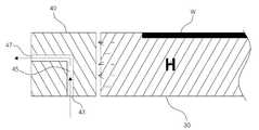
도 2는 도 1에 도시한 냉각링을 통해 냉매의 유동 흐름에 따른 히터의 열교환 상태를 나타내는 도면이다.
도 3은 도 1에 도시한 냉각링에 형성된 가스유로들의 배치상태를 나타내는 도면이다.
도 4는 도 2에 도시한 냉각링의 다른 실시예를 나타내는 도면이다.
도 5는 도 1에 도시한 가스유로와 가스공급관의 연결상태를 나타내는 도면이다.
도 6은 본 발명의 다른 실시예에 따른 기판처리장치를 개략적으로 나타내는 도면이다.
도 7은 본 발명의 또 다른 실시예에 따른 기판처리장치를 개략적으로 나타내는 도면이다.1 is a schematic view of a substrate processing apparatus according to an embodiment of the present invention.
FIG. 2 is a view showing a heat exchange state of a heater according to a flow of a coolant through a cooling ring shown in FIG. 1. FIG.
Fig. 3 is a view showing the arrangement of the gas channels formed in the cooling ring shown in Fig. 1. Fig.
Fig. 4 is a view showing another embodiment of the cooling ring shown in Fig. 2. Fig.
5 is a view showing the connection state of the gas flow path and the gas supply pipe shown in Fig.
6 is a view schematically showing a substrate processing apparatus according to another embodiment of the present invention.
7 is a view schematically showing a substrate processing apparatus according to another embodiment of the present invention.
이하, 본 발명의 바람직한 실시예들을 첨부된 도 1 내지 도 7을 참고하여 더욱 상세히 설명한다. 본 발명의 실시예들은 여러 가지 형태로 변형될 수 있으며, 본 발명의 범위가 아래에서 설명하는 실시예들에 한정되는 것으로 해석되어서는 안 된다. 본 실시예들은 당해 발명이 속하는 기술분야에서 통상의 지식을 가진 자에게 본 발명을 더욱 상세하게 설명하기 위해서 제공되는 것이다. 따라서 도면에 나타난 각 요소의 형상은 보다 분명한 설명을 강조하기 위하여 과장될 수 있다. 또한, 실시예에서 설명하는 기판(W) 외에 다양한 피처리체에도 응용될 수 있음은 당업자로서 당연하다.
Hereinafter, preferred embodiments of the present invention will be described in detail with reference to the accompanying drawings. The embodiments of the present invention can be modified in various forms, and the scope of the present invention should not be construed as being limited to the embodiments described below. The embodiments are provided to explain the present invention to a person having ordinary skill in the art to which the present invention belongs. Accordingly, the shape of each element shown in the drawings may be exaggerated to emphasize a clearer description. It is obvious to those skilled in the art that the present invention can be applied to various substrates other than the substrate W described in the embodiments.
도 1은 본 발명의 일 실시예에 따른 기판처리장치를 개략적으로 나타내는 도면이다. 도 1에 도시한 바와 같이, 기판처리장치(1)는 메인챔버(10)와 챔버 덮개(20)를 포함한다. 메인챔버(10)는 상부가 개방된 형상이며, 일측에 기판(W)이 출입가능한 통로(도시안함)를 가질 수 있다. 기판(W)은 메인챔버(10)의 일측에 형성된 통로를 통해 메인챔버(10)의 내부로 출입할 수 있다. 게이트밸브(도시안함)는 통로의 외부에 설치되며, 통로는 게이트밸브에 의해 개방되거나 폐쇄될 수 있다.
1 is a schematic view of a substrate processing apparatus according to an embodiment of the present invention. As shown in FIG. 1, the substrate processing apparatus 1 includes a
챔버덮개(20)는 메인챔버(10)의 개방된 상부에 연결되며, 외부로부터 차단하여 공정공간(3)을 가진다. 메인챔버(10)와 챔버덮개(20) 사이에는 실링부재(도시안함)가 설치될 수 있으며, 공정공간(3)을 완전히 밀폐시킬 수 있다. 가스공급구(75)는 챔버덮개(20)의 천정벽을 관통하도록 형성되며, 공정가스공급관(77)를 통해 공정가스는 메인챔버(10) 내부로 공급된다. 공정가스공급관(77)은 공정가스저장탱크(70)에 연결되어 벨브(89)를 개폐하여 공정가스 투입량 조절이 가능하다.
The
챔버덮개(20)의 하단면에는 복수개의 확산홀(65)을 구비하는 샤워헤드(60)이 설치된다. 샤워헤드(60)은 동일한 높이에 형성된 복수개의 확산홀(65)을 통해 공정가스를 기판(W) 상에 골고루 공급한다. 공정가스는 수소(H2) 또는 질소(N2) 또는 소정의 다른 불활성 가스를 포함할 수 있으며, 실란(SiH4) 또는 디클로로실란(SiH2Cl2)과 같은 프리커서 가스들을 포함할 수 있다. 또한, 디보란(B2H6) 또는 포스핀(PH3)과 같은 도펀트 소스 가스들을 포함할 수 있다. 샤워헤드(60)은 가스공급구(75)를 통해 공급된 공정가스를 기판(W)을 향해 확산하여 유동한다. 샤워헤드(60)를 통해 공급된 가스는 소정의 공정을 마친 뒤, 메인챔버(10)의 타측에 형성된 배기통로(13)를 통해 배기될 수 있다.
A
기판처리장치(1)의 공정공간(3)에는 히터(30)가 설치된다. 히터(30)는 외부전원(도시안함)으로부터 전류를 공급받아 발열하며, 히터(30)의 상부면은 기판(W)이 로딩되어 안착되는 안착홈(도시안함)이 형성될 수 있다. 히터(30)는 기판(W)을 균일하게 가열하기 위해 기판(W)의 형상과 대응되는 원형 디스크 형상을 가질 수 있으며, 기판(W)의 면적보다 더 넓다. 히터의 중앙부 하측에는 관통공(31)이 형성되며, 지지축(35)은 히터(30)의 하부에 연결되어 히터(30)를 지지한다. 지지축(35)은 구동부(도시안함)와 연결되어 히터(30)와 함께 회전할 수 있다.
A heater (30) is installed in the processing space (3) of the substrate processing apparatus (1). The
또한, 기판처리장치(1)의 내부공간(3)은 기판(W)을 처리하는데 있어서, 내부 분위기를 진공상태 및 기판처리장치(1) 외부의 분위기를 차단하기 위해 벨로우즈(38)를 더 포함할 수 있다. 벨로우즈(38)는 메인챔버(10)의 관통공(31)에 설치된 상부고정부재(33) 하부의 일측과 연결될 수 있다. 벨로우즈(38)는 압축 및 신장 가능하며, 환형으로 형성되는 것이 바람직하다. 또한, 벨로우즈(38)는 지지축(35)을 감싼 상태로 상부고정부재(33)와 하부고정부재(도시안함) 사이에 배치된다.
The
가이드부재(80)는 메인챔버(10)의 바닥면과 측면을 따라 설치된다. 가이드부재(80)는 메인챔버(10)의 바닥면에 설치되는 바닥판(82), 메인챔버(10)의 측면을 따라 설치되는 원통형상의 측판(84) 및 측판(84)의 내주면을 따라 연결되어 히터(30)를 향해 돌출되는 지지부재(86)를 포함한다. 가이드부재(80)의 내면에는 복수의 가스공급관(97)들을 가지며, 가스공급관(97)들은 각각 연결관(95)들과 연결된다. 연결관(95)은 상부고정부재(33)를 관통하여 삽입설치될 수 있다. 연결관(95)은 상부고정부재를 관통하여 관통공(31)의 측벽을 따라 바닥판(82)에 형성된 가스공급관(97)들에 각각 연통된다. 즉, 냉매는 냉매저장탱크(90)로부터 연결된 연결관(95) 및 가스공급관(97)들을 통해 후술하는 냉각링(40)의 가스유로(45)를 통과한 후 배출된다.
The
최근 기판(W)의 사이즈가 대형화됨에 따라, 히터(30)의 사이즈 또한 함께 증가하는 추세이다. 이로 인해, 기판(W) 상의 균일한 온도분포를 형성하는데 어려움이 발생한다. 즉, 기판(W)을 기설정된 공정온도로 가열하는 과정에서, 히터의 고장 또는 성능저하, 그리고, 히터(W)의 복사열이 국부적으로 불균형해질 수 있는 문제점을 개선하고자 히터(W)의 둘레를 따라 냉각링(40)을 설치하여 히터(W)의 국부적 온도변화로 인해 발생되는 기판(W)의 온도변화를 최소화할 수 있다. 지지부재(86)의 상단부에는 냉각링(40)이 설치된다. 냉각링(40)은 히터(W)의 둘레에 기설정된 간격으로 이격 배치될 수 있으며, 바람직하게는 10 mm 이하의 간격으로 설치될 수 있다. 또한, 냉각링(40)은 히터(W)의 고온에 잘 견디는 내화물 재료로 설치되며, 열팽창계수가 작고, 열전도계수를 높이기 위해, Al2O3 와 Y2O3 등을 코팅할 수 있다.
As the size of the substrate W becomes larger recently, the size of the
냉각링(40)은 복수개의 가스유로(45)들을 가지며, 가스유로(45)들은 각각 대응되는 가스공급관(97)들과 연결된다. 유입구(도2의 43)를 통해 가스공급관(97)들과 연통되어 냉매가 가스유로(45)를 향해 유입되며, 냉매는 유출구(도2의 47)를 통해 배출된다. 연결부재(88)는 측판(84)의 상부에 기립설치되며, 배기링(50)은 연결부재(88)의 상단부에 연결된다. 바람직하게는 샤워헤드(60)의 측하단부와 연결부재(88)의 상단부에 연결되어 공정공간(3)과 격리할 수 있다.
The
배기링(50)은 상하부에 각각 공정가스배출홀(53)들 및 냉매배출홀(57)들이 기설정된 간격으로 형성된다. 샤워헤드(60)를 통해 분산된 공정가스는 기판(W)과의 소정의 공정 이후, 공정가스배출홀(53)들을 통해 배기포트(15)로 배출되며, 냉각링(40)의 가스유로(45)로 공급된 냉매는 유출구(도 2의 47)와 대응되는 위치에 형성되는 냉매배출홀(57)들을 통해 배기포트(15)로 배출된다. 배기라인(17)은 배기포트(15)에 연결되며, 공정가스배출홀(53)들을 통해 배출되는 미반응가스 또는 반응생성물, 그리고 냉매배출홀(57)들을 통해 배출되는 냉매가스들은 배기라인(17)을 통해 배출된다. 이 가스들은 배기라인(17)에 연결된 배기펌프(19)를 통해 외부로 강제 배출될 수 있다.
The
도 2는 도 1에 도시한 냉각링을 통해 냉매의 유동 흐름에 따른 히터의 열교환 상태를 나타내는 도면이다. 앞서 설명한 바와 같이, 냉각링(40)은 복수개의 가스유로(45)들을 가진다. 도 2에 도시한 바와 같이, 가스유로(45)는 각각 대응되는 가스공급관(97)에 연통되어 냉매를 공급받는다. 가스유로(45)는 유입구(43)와 유출구(47)를 가지며, 유입구(43)를 통해 공급된 냉매는 가스유로(45)를 통과하여 유출구(47)로 배출됨에 따라 냉매가 공급되는 기설정된 히터(30) 영역의 온도는 감소된다. 즉, 히터(30)의 국부적인 온도편차는 가스유로(45)를 통해 냉매를 공급함으로써 히터(30) 전체의 균일한 온도구배를 가져올 수 있다.
FIG. 2 is a view showing a heat exchange state of a heater according to a flow of a coolant through a cooling ring shown in FIG. 1. FIG. As described above, the cooling
도 3은 도 1에 도시한 냉각링에 형성된 가스유로(45)들의 배치상태를 나타내는 도면이다. 도 3에 도시한 바와 같이 냉각링(40)은 복수개의 가스유로(45)들을 가진다. 가스유로(45)들은 히터(30)의 중심(C)으로 등각을 이루어 배치되며, 가스유로(45)의 지름은 0.5 ~ 5mm 가 바람직하다. 본 실시예에서는 24개의 가스유로(45)를 가지는 냉각링(40)을 예를 들어 설명하나, 가스유로(45)의 개수는 기설정된 간격으로 추가하거나 줄일 수 있다.
3 is a view showing the arrangement of the
예를 들어, 24개의 가스유로(45)를 가지는 냉각링(40)이 설치될 경우, 히터(30) 또한 24개의 구역(zone)으로 구획될 수 있다. 이 중, 상대적으로 높은 온도를 가지는 구역(H)에 해당하는 가스유로(45)에 연결된 밸브(도시안함)를 개방하여 냉매를 유동시킬 경우, 냉각링(40) 중 구역(H)에 해당하는 부분이 냉매에 의해 냉각되며, 이를 통해 구역(H)을 간접냉각함으로써 구역별 온도를 균일하게 조절할 수 있다.
For example, when the
한편, 본 실시예에서는 가스유로(45)의 내부를 흐르는 냉매가 유출구(47)를 통해 냉각링(40)의 외측으로 배출되는 것으로 설명하고 있으나, 도 4에 도시한 바와 같이, 냉매는 냉각링(40)의 내측으로 배출되어 히터(30)에 직접 분사될 수 있으며, 유출구(47)는 냉각링(40)의 내측을 향해 개방될 수 있다. 히터(30)는 냉각링(40)으로부터 분사된 냉매를 통해 직접 냉각될 수 있다.
In the present embodiment, the refrigerant flowing in the
도 5는 도 1에 도시한 가스유로(45)들과 가스공급관(97)들의 연결상태를 나타내는 도면이다. 앞서 설명한 바와 같이, 가스유로(45)들은 각각에 대응되는 가스공급관(97)들과 연결된다. 제1 가스유로는 제1 가스공급관과 연결되며, 제2 가스유로는 제2 가스공급관과 연결된다. 각각의 가스공급관(97)에는 냉매의 공급을 제어하는 밸브가 설치되며, 밸브는 가스공급관(97)을 개폐 또는 유량을 조절하여 각각의 가스유로(45)에 냉매 공급을 제어할 수 있다. 따라서, 가스유로(45)에 냉매를 공급함으로써 히터(30)의 국부적 온도 차이를 최소화하여 기판(W)을 가열함으로써, 기판(W)의 공정균일도를 향상시킬 수 있다.
5 is a view showing the connection state of the
도 6은 본 발명의 다른 실시예에 따른 기판처리장치를 개략적으로 나타내는 도면이다. 앞서, 도 1 내지 도 5를 통해 설명한 바와 후술하는 구성요소들과 실질적으로 동일한 구성요소들을 나타내는 도면부호는 도 1 내지 도 5의 것과 동일하게 부여하고, 이들 부위에 대한 상세한 설명은 앞서 설명한 내용으로 대체될 수 있다. 도 5에서는 설명의 편의상 도 1의 기판처리장치(1)와의 차이점을 중심으로 설명하기로 한다.
6 is a view schematically showing a substrate processing apparatus according to another embodiment of the present invention. 1 to 5 are denoted by the same reference numerals as those shown in Figs. 1 to 5, and detailed descriptions of these parts are omitted from the above description Can be replaced. 5, the difference from the substrate processing apparatus 1 of FIG. 1 will be mainly described for convenience of explanation.
도 6에 도시한 바와 같이, 지지부재(84)와 샤워헤드(60) 사이에는 냉각링(40)이 설치되어 공정공간(3)을 격리시킬 수 있다. 냉각링(40)의 하부면에는 복수개의 가스유로(45)들이 기설정된 간격으로 형성되며, 상부면에는 복수개의 상부배출홀(48)들이 형성된다. 냉각링(40)에 형성되는 가스유로(45)들은 각각의 냉매공급관(97)과 연통되어 냉매를 공급받는다. 가스유로(45)들 통해 냉매를 공급함으로써 히터(30)의 국부적 온도편차를 제어가능하며, 냉각링(40)의 상부면에 형성된 상부배출홀(48)들을 통해 공정 후의 반응생성물 또는 미반응가스들을 배기포트(15)를 통해 외부로 배출가능하다. 즉, 도 1에 도시한 바와 달리, 별도로 배기링을 구비하지 않고, 냉각링(40) 자체만으로도 히터(30)의 온도균일화 및 공정가스의 배출이 가능하다. 따라서, 가스유로(45)에 공급되는 냉매를 통해 히터(30)의 국부적 온도차이를 최소화하여 기판(W)을 가열함으로써, 기판(W)의 품질을 향상시킬 수 있다.
6, a
도 7은 본 발명의 또 다른 실시예에 따른 기판처리장치를 개략적으로 나타내는 도면이다. 도 7에 도시한 바와 같이, 연결관(95)은 샤워헤드(60)의 플랜지부 및 챔버덮개(20)를 관통하여 설치될 수 있으며, 연결관(95)은 냉매저장탱크(90)에 연결될 수 있다.
7 is a view schematically showing a substrate processing apparatus according to another embodiment of the present invention. 7, the
상술한 바에 의하면, 냉각링(40)을 히터(30)의 둘레에 설치하고, 냉각링(40)에 냉매를 위치에 따라 선택적으로 공급함으로써 냉각링(40)의 일부 영역을 냉각할 수 있으며, 이를 통해 히터(30)의 일부 영역을 냉각함으로써 히터(30)의 온도불균일을 조절할 수 있다. 특히, 냉매는 불활성가스일 수 있으며, 불활성가스는 공정에 직접적인 영향을 미치지 않으므로, 공정진행 중에도 히터(30)의 온도불균일을 조절하여 공정의 균일도를 개선할 수 있다.
The
본 발명을 바람직한 실시예들을 통하여 상세하게 설명하였으나, 이와 다른 형태의 실시예들도 가능하다. 그러므로, 이하에 기재된 청구항들의 기술적 사상과 범위는 바람직한 실시예들에 한정되지 않는다.Although the present invention has been described in detail by way of preferred embodiments thereof, other forms of embodiment are possible. Therefore, the technical idea and scope of the claims set forth below are not limited to the preferred embodiments.
1 : 기판처리장치10 : 메인챔버
13 : 배기통로15 : 배기포트
17 : 배기라인19 : 배기펌프
20 : 챔버덮개30 : 히터
35 : 지지축40 : 냉각링
45 : 가스유로50 : 배기링
60 : 샤워헤드65 : 분산홀
70 : 공정가스저장탱크80 : 가이드부재
90 : 냉매저장탱크95 : 연결관
97 : 가스공급관1: substrate processing apparatus 10: main chamber
13: exhaust passage 15: exhaust port
17: exhaust line 19: exhaust pump
20: chamber cover 30: heater
35: support shaft 40: cooling ring
45: gas channel 50: exhaust ring
60: Showerhead 65: Dispersion hole
70: process gas storage tank 80: guide member
90: Refrigerant storage tank 95: Connection pipe
97: gas supply pipe
Claims (10)
Translated fromKorean상기 공정공간에 설치되어 상기 기판이 상부에 놓여지며, 상기 기판을 가열하는 히터; 및
상기 히터의 둘레를 따라 배치되며, 복수개의 가스유로들이 상기 히터의 둘레를 따라 이격형성되는 냉각링;
각각의 상기 가스유로에 연결되어 외부로부터 공급된 냉매를 상기 가스유로에 공급가능한 복수의 가스공급관들; 및
각각의 상기 가스공급관에 설치되어 상기 가스공급관으로부터 상기 가스유로에 공급되는 상기 냉매의 유량을 조절하는 복수의 밸브들을 포함하는, 기판처리장치.A main chamber having a process space in which a process is performed on a substrate;
A heater installed in the process space and having the substrate placed thereon, the heater heating the substrate; And
A cooling ring disposed along the circumference of the heater and having a plurality of gas passages spaced apart along the circumference of the heater;
A plurality of gas supply pipes connected to each of the gas passages to supply the refrigerant supplied from the outside to the gas passages; And
And a plurality of valves installed in each of the gas supply pipes to adjust a flow rate of the refrigerant supplied from the gas supply pipe to the gas flow path.
상기 냉각링은 상기 가스유로에 연결되어 상기 냉각링의 내측 또는 외측을 향해 개방된 유출구를 가지는 것을 특징으로 하는 기판처리장치.The method of claim 1,
And the cooling ring has an outlet connected to the gas passage and open toward the inside or the outside of the cooling ring.
상기 공정공간에 설치되어 상기 기판이 상부에 놓여지며, 상기 기판을 가열하는 히터;
상기 히터의 둘레를 따라 배치되며, 복수개의 가스유로들이 상기 히터의 둘레를 따라 이격형성되어 외부로부터 공급된 냉매가 흐르는 냉각링; 및
상기 공정공간에 설치되며, 외부로부터 공급된 냉매를 상기 유로들을 향해 각각 공급하는 가스공급관들을 가지는 가이드부재를 더 포함하되,
상기 냉각링은 상기 가스유로에 연결되어 상기 냉각링의 내측 또는 외측을 향해 개방된 유출구를 가지며,
상기 가이드부재는,
상기 메인챔버의 바닥면을 따라 연결되는 바닥판;
상기 바닥판의 측부를 따라 연결되는 측판; 및
상기 히터를 향해 돌출되어 상기 측판에 연결되며, 상기 냉각링을 지지하는 지지부재를 더 포함하는 것을 특징으로 하는 기판처리장치.A main chamber having a process space in which a process is performed on a substrate;
A heater installed in the process space and having the substrate placed thereon, the heater heating the substrate;
A cooling ring disposed along the circumference of the heater and having a plurality of gas passages spaced apart along the circumference of the heater to allow a refrigerant supplied from the outside to flow; And
It is installed in the process space, and further comprising a guide member having a gas supply pipe for supplying the refrigerant supplied from the outside toward the flow path, respectively,
The cooling ring has an outlet connected to the gas flow path open toward the inside or the outside of the cooling ring,
The guide member
A bottom plate connected along the bottom surface of the main chamber;
A side plate connected along a side of the bottom plate; And
And a support member protruding toward the heater and connected to the side plate and supporting the cooling ring.
상기 가이드부재는 상기 측판의 상부에 기립설치되는 돌출부를 가지며,
상기 기판처리장치는,
상기 돌출부의 상부에 연결되어 샤워헤드를 통해 공급된 공정가스를 외부로 배출가능한 공정가스배출홀들 및 상기 유출구들과 대응되는 위치에 형성되어 상기 냉매를 외부로 배출가능한 냉매배출홀들을 가지는 배기링을 더 구비하는 것을 특징으로 하는 기판처리장치.The method of claim 3,
The guide member has a protruding portion standing up on the upper side of the side plate,
The substrate processing apparatus includes:
An exhaust ring connected to an upper portion of the protruding portion to have process gas discharge holes for discharging the process gas supplied through a shower head to the outside, and a refrigerant discharge holes formed at positions corresponding to the outlets to discharge the refrigerant to the outside; Substrate processing apparatus characterized in that it further comprises.
상기 가스공급관들에 각각 연결되어 상기 가스공급관들을 개폐하는 밸브를 구비하는 것을 특징으로 하는 기판처리장치.The method of claim 3,
And a valve connected to each of the gas supply pipes to open and close the gas supply pipes.
상기 냉각링은 상기 가스유로의 상부에 배치되며, 샤워헤드를 통해 공급된 공정가스를 외부로 배출가능한 상부배출홀들을 가지는 것을 특징으로 하는 기판처리장치.The method of claim 3,
The cooling ring is disposed above the gas flow path, the substrate processing apparatus, characterized in that it has an upper discharge hole for discharging the process gas supplied through the shower head to the outside.
상기 가스유로들은 상기 히터를 중심으로 등각을 이루어 배치되는 것을 특징으로 하는 기판처리장치.The method of claim 1,
The gas passages are disposed at an equiangular center with respect to the heater.
상기 냉각링은 상기 히터로부터 이격배치되는 것을 특징으로 하는 기판처리장치.The method of claim 1,
And the cooling ring is spaced apart from the heater.
Priority Applications (5)
| Application Number | Priority Date | Filing Date | Title |
|---|---|---|---|
| KR1020120148665AKR101375742B1 (en) | 2012-12-18 | 2012-12-18 | Apparatus for processing substrate |
| JP2015545382AJP6088659B2 (en) | 2012-12-18 | 2013-12-18 | Substrate processing apparatus and heater temperature control method |
| CN201380066374.7ACN104871292B (en) | 2012-12-18 | 2013-12-18 | Substrate treatment apparatus, and method for controlling temperature of heater |
| PCT/KR2013/011839WO2014098486A1 (en) | 2012-12-18 | 2013-12-18 | Substrate treatment apparatus, and method for controlling temperature of heater |
| US14/646,079US9758870B2 (en) | 2012-12-18 | 2013-12-18 | Substrate treatment apparatus, and method for controlling temperature of heater |
Applications Claiming Priority (1)
| Application Number | Priority Date | Filing Date | Title |
|---|---|---|---|
| KR1020120148665AKR101375742B1 (en) | 2012-12-18 | 2012-12-18 | Apparatus for processing substrate |
Related Child Applications (1)
| Application Number | Title | Priority Date | Filing Date |
|---|---|---|---|
| KR1020140018039ADivisionKR101452829B1 (en) | 2014-02-17 | 2014-02-17 | Method for adjusting temperature of heater |
Publications (1)
| Publication Number | Publication Date |
|---|---|
| KR101375742B1true KR101375742B1 (en) | 2014-03-19 |
Family
ID=50649024
Family Applications (1)
| Application Number | Title | Priority Date | Filing Date |
|---|---|---|---|
| KR1020120148665AActiveKR101375742B1 (en) | 2012-12-18 | 2012-12-18 | Apparatus for processing substrate |
Country Status (5)
| Country | Link |
|---|---|
| US (1) | US9758870B2 (en) |
| JP (1) | JP6088659B2 (en) |
| KR (1) | KR101375742B1 (en) |
| CN (1) | CN104871292B (en) |
| WO (1) | WO2014098486A1 (en) |
Cited By (1)
| Publication number | Priority date | Publication date | Assignee | Title |
|---|---|---|---|---|
| WO2018097445A1 (en)* | 2016-11-23 | 2018-05-31 | 주식회사 조인솔루션 | Cooler of substrate processing chamber |
Families Citing this family (9)
| Publication number | Priority date | Publication date | Assignee | Title |
|---|---|---|---|---|
| US9963782B2 (en)* | 2015-02-12 | 2018-05-08 | Asm Ip Holding B.V. | Semiconductor manufacturing apparatus |
| US10801106B2 (en)* | 2016-12-15 | 2020-10-13 | Asm Ip Holding B.V. | Shower plate structure for exhausting deposition inhibiting gas |
| CN106987808B (en)* | 2017-05-15 | 2019-04-09 | 成都西沃克真空科技有限公司 | A kind of coating machine substrate heating device |
| JP7008602B2 (en)* | 2018-09-27 | 2022-01-25 | 東京エレクトロン株式会社 | Film forming equipment and temperature control method |
| JP7477515B2 (en)* | 2019-01-08 | 2024-05-01 | アプライド マテリアルズ インコーポレイテッド | Pumping apparatus and method for a substrate processing chamber - Patents.com |
| KR102315665B1 (en)* | 2019-08-19 | 2021-10-22 | 세메스 주식회사 | Apparatus for treating substrate |
| CN111668140B (en)* | 2020-07-02 | 2025-07-18 | 沈阳芯源微电子设备股份有限公司 | Adjusting device and method based on ceramic heater temperature consistency |
| CN114402425B (en) | 2020-08-18 | 2025-08-15 | 玛特森技术公司 | Rapid thermal processing system with cooling system |
| CN112251737A (en)* | 2020-10-29 | 2021-01-22 | 常州捷佳创精密机械有限公司 | Heating chamber structure and wafer processing equipment |
Citations (4)
| Publication number | Priority date | Publication date | Assignee | Title |
|---|---|---|---|---|
| KR20010027089A (en)* | 1999-09-10 | 2001-04-06 | 김영환 | heater block for film deposition in fabrication of semiconductor |
| KR20070014716A (en)* | 2005-07-29 | 2007-02-01 | 삼성전자주식회사 | The temperature drop of the heater block |
| JP2009170676A (en)* | 2008-01-16 | 2009-07-30 | Toshiba Corp | Epitaxial wafer manufacturing apparatus and manufacturing method |
| US20100002355A1 (en) | 2008-07-02 | 2010-01-07 | Ngk Insulators, Ltd. | Wafer support device and component used for the same |
Family Cites Families (9)
| Publication number | Priority date | Publication date | Assignee | Title |
|---|---|---|---|---|
| JP2560986B2 (en)* | 1993-07-27 | 1996-12-04 | 日本電気株式会社 | Tungsten CVD equipment |
| JP3665672B2 (en)* | 1995-11-01 | 2005-06-29 | 東京エレクトロン株式会社 | Film forming apparatus and film forming method |
| JP2002198297A (en)* | 2000-12-27 | 2002-07-12 | Kyocera Corp | Wafer heating device |
| JP2005136025A (en)* | 2003-10-29 | 2005-05-26 | Trecenti Technologies Inc | Semiconductor manufacturing apparatus, method of manufacturing semiconductor device, and wafer stage |
| TWI574318B (en)* | 2004-06-21 | 2017-03-11 | Tokyo Electron Ltd | A plasma processing apparatus, a plasma processing method, and a computer-readable recording medium |
| JP5089401B2 (en)* | 2007-02-09 | 2012-12-05 | 株式会社日立国際電気 | Thermal insulation structure, heating apparatus, heating system, substrate processing apparatus, and semiconductor device manufacturing method |
| WO2011052817A1 (en)* | 2009-10-28 | 2011-05-05 | 엘아이지에이디피 주식회사 | Metal organic chemical vapor deposition device and temperature control method therefor |
| JP2011096894A (en)* | 2009-10-30 | 2011-05-12 | Toshiba Corp | Method and apparatus for manufacturing semiconductor device |
| US8552346B2 (en)* | 2011-05-20 | 2013-10-08 | Applied Materials, Inc. | Methods and apparatus for controlling temperature of a multi-zone heater in an process chamber |
- 2012
- 2012-12-18KRKR1020120148665Apatent/KR101375742B1/enactiveActive
- 2013
- 2013-12-18JPJP2015545382Apatent/JP6088659B2/enactiveActive
- 2013-12-18WOPCT/KR2013/011839patent/WO2014098486A1/enactiveApplication Filing
- 2013-12-18USUS14/646,079patent/US9758870B2/enactiveActive
- 2013-12-18CNCN201380066374.7Apatent/CN104871292B/enactiveActive
Patent Citations (4)
| Publication number | Priority date | Publication date | Assignee | Title |
|---|---|---|---|---|
| KR20010027089A (en)* | 1999-09-10 | 2001-04-06 | 김영환 | heater block for film deposition in fabrication of semiconductor |
| KR20070014716A (en)* | 2005-07-29 | 2007-02-01 | 삼성전자주식회사 | The temperature drop of the heater block |
| JP2009170676A (en)* | 2008-01-16 | 2009-07-30 | Toshiba Corp | Epitaxial wafer manufacturing apparatus and manufacturing method |
| US20100002355A1 (en) | 2008-07-02 | 2010-01-07 | Ngk Insulators, Ltd. | Wafer support device and component used for the same |
Cited By (1)
| Publication number | Priority date | Publication date | Assignee | Title |
|---|---|---|---|---|
| WO2018097445A1 (en)* | 2016-11-23 | 2018-05-31 | 주식회사 조인솔루션 | Cooler of substrate processing chamber |
Also Published As
| Publication number | Publication date |
|---|---|
| CN104871292B (en) | 2017-04-26 |
| JP2016506070A (en) | 2016-02-25 |
| US9758870B2 (en) | 2017-09-12 |
| WO2014098486A1 (en) | 2014-06-26 |
| CN104871292A (en) | 2015-08-26 |
| JP6088659B2 (en) | 2017-03-01 |
| US20150299860A1 (en) | 2015-10-22 |
Similar Documents
| Publication | Publication Date | Title |
|---|---|---|
| KR101375742B1 (en) | Apparatus for processing substrate | |
| US10145012B2 (en) | Substrate processing apparatus and substrate processing method | |
| KR101387518B1 (en) | Apparatus for processing substrate | |
| JP6002837B2 (en) | Substrate processing equipment | |
| KR101440307B1 (en) | Apparatus for processing substrate | |
| KR20080112437A (en) | Shower head for thin film deposition apparatus and cleaning method for thin film deposition apparatus | |
| WO2015195256A1 (en) | One-piece injector assembly | |
| TWI741220B (en) | Showerhead and substrate processing apparatus including the same | |
| KR101452829B1 (en) | Method for adjusting temperature of heater | |
| KR20230085686A (en) | Apparatus for processing substrate | |
| US20150191821A1 (en) | Substrate processing device | |
| TWI569346B (en) | Substrate processing apparatus and method for adjusting temperature of heater | |
| JP7468926B2 (en) | Shower head and substrate processing apparatus |
Legal Events
| Date | Code | Title | Description |
|---|---|---|---|
| A201 | Request for examination | ||
| PA0109 | Patent application | Patent event code:PA01091R01D Comment text:Patent Application Patent event date:20121218 | |
| PA0201 | Request for examination | ||
| E902 | Notification of reason for refusal | ||
| PE0902 | Notice of grounds for rejection | Comment text:Notification of reason for refusal Patent event date:20130925 Patent event code:PE09021S01D | |
| E90F | Notification of reason for final refusal | ||
| PE0902 | Notice of grounds for rejection | Comment text:Final Notice of Reason for Refusal Patent event date:20140127 Patent event code:PE09021S02D | |
| A107 | Divisional application of patent | ||
| PA0107 | Divisional application | Comment text:Divisional Application of Patent Patent event date:20140217 Patent event code:PA01071R01D | |
| E701 | Decision to grant or registration of patent right | ||
| PE0701 | Decision of registration | Patent event code:PE07011S01D Comment text:Decision to Grant Registration Patent event date:20140311 | |
| GRNT | Written decision to grant | ||
| PR0701 | Registration of establishment | Comment text:Registration of Establishment Patent event date:20140312 Patent event code:PR07011E01D | |
| PR1002 | Payment of registration fee | Payment date:20140312 End annual number:3 Start annual number:1 | |
| PG1601 | Publication of registration | ||
| FPAY | Annual fee payment | Payment date:20170222 Year of fee payment:4 | |
| PR1001 | Payment of annual fee | Payment date:20170222 Start annual number:4 End annual number:4 | |
| FPAY | Annual fee payment | Payment date:20190227 Year of fee payment:6 | |
| PR1001 | Payment of annual fee | Payment date:20190227 Start annual number:6 End annual number:6 | |
| FPAY | Annual fee payment | Payment date:20200227 Year of fee payment:7 | |
| PR1001 | Payment of annual fee | Payment date:20200227 Start annual number:7 End annual number:7 | |
| PR1001 | Payment of annual fee | Payment date:20210302 Start annual number:8 End annual number:8 | |
| PR1001 | Payment of annual fee | Payment date:20220302 Start annual number:9 End annual number:11 | |
| PR1001 | Payment of annual fee | Payment date:20241230 Start annual number:12 End annual number:14 |