KR101373600B1 - Transparent lens of led module assembly and apparatus for displaying traffic information using it - Google Patents
Transparent lens of led module assembly and apparatus for displaying traffic information using itDownload PDFInfo
- Publication number
- KR101373600B1 KR101373600B1KR1020120069548AKR20120069548AKR101373600B1KR 101373600 B1KR101373600 B1KR 101373600B1KR 1020120069548 AKR1020120069548 AKR 1020120069548AKR 20120069548 AKR20120069548 AKR 20120069548AKR 101373600 B1KR101373600 B1KR 101373600B1
- Authority
- KR
- South Korea
- Prior art keywords
- led module
- lens
- module assembly
- led
- light transmitting
- Prior art date
- Legal status (The legal status is an assumption and is not a legal conclusion. Google has not performed a legal analysis and makes no representation as to the accuracy of the status listed.)
- Expired - Fee Related
Links
Images


Classifications
- F—MECHANICAL ENGINEERING; LIGHTING; HEATING; WEAPONS; BLASTING
- F21—LIGHTING
- F21K—NON-ELECTRIC LIGHT SOURCES USING LUMINESCENCE; LIGHT SOURCES USING ELECTROCHEMILUMINESCENCE; LIGHT SOURCES USING CHARGES OF COMBUSTIBLE MATERIAL; LIGHT SOURCES USING SEMICONDUCTOR DEVICES AS LIGHT-GENERATING ELEMENTS; LIGHT SOURCES NOT OTHERWISE PROVIDED FOR
- F21K9/00—Light sources using semiconductor devices as light-generating elements, e.g. using light-emitting diodes [LED] or lasers
- F21K9/60—Optical arrangements integrated in the light source, e.g. for improving the colour rendering index or the light extraction
- F21K9/69—Details of refractors forming part of the light source
- E—FIXED CONSTRUCTIONS
- E01—CONSTRUCTION OF ROADS, RAILWAYS, OR BRIDGES
- E01F—ADDITIONAL WORK, SUCH AS EQUIPPING ROADS OR THE CONSTRUCTION OF PLATFORMS, HELICOPTER LANDING STAGES, SIGNS, SNOW FENCES, OR THE LIKE
- E01F9/00—Arrangement of road signs or traffic signals; Arrangements for enforcing caution
- E01F9/60—Upright bodies, e.g. marker posts or bollards; Supports for road signs
- E01F9/604—Upright bodies, e.g. marker posts or bollards; Supports for road signs specially adapted for particular signalling purposes, e.g. for indicating curves, road works or pedestrian crossings
- F—MECHANICAL ENGINEERING; LIGHTING; HEATING; WEAPONS; BLASTING
- F21—LIGHTING
- F21V—FUNCTIONAL FEATURES OR DETAILS OF LIGHTING DEVICES OR SYSTEMS THEREOF; STRUCTURAL COMBINATIONS OF LIGHTING DEVICES WITH OTHER ARTICLES, NOT OTHERWISE PROVIDED FOR
- F21V33/00—Structural combinations of lighting devices with other articles, not otherwise provided for
- F21V33/0064—Health, life-saving or fire-fighting equipment
- F21V33/0076—Safety or security signalisation, e.g. smoke or burglar alarms, earthquake detectors; Self-defence devices
- F—MECHANICAL ENGINEERING; LIGHTING; HEATING; WEAPONS; BLASTING
- F21—LIGHTING
- F21V—FUNCTIONAL FEATURES OR DETAILS OF LIGHTING DEVICES OR SYSTEMS THEREOF; STRUCTURAL COMBINATIONS OF LIGHTING DEVICES WITH OTHER ARTICLES, NOT OTHERWISE PROVIDED FOR
- F21V5/00—Refractors for light sources
- F21V5/007—Array of lenses or refractors for a cluster of light sources, e.g. for arrangement of multiple light sources in one plane
- F—MECHANICAL ENGINEERING; LIGHTING; HEATING; WEAPONS; BLASTING
- F21—LIGHTING
- F21V—FUNCTIONAL FEATURES OR DETAILS OF LIGHTING DEVICES OR SYSTEMS THEREOF; STRUCTURAL COMBINATIONS OF LIGHTING DEVICES WITH OTHER ARTICLES, NOT OTHERWISE PROVIDED FOR
- F21V5/00—Refractors for light sources
- F21V5/04—Refractors for light sources of lens shape
- F—MECHANICAL ENGINEERING; LIGHTING; HEATING; WEAPONS; BLASTING
- F21—LIGHTING
- F21V—FUNCTIONAL FEATURES OR DETAILS OF LIGHTING DEVICES OR SYSTEMS THEREOF; STRUCTURAL COMBINATIONS OF LIGHTING DEVICES WITH OTHER ARTICLES, NOT OTHERWISE PROVIDED FOR
- F21V5/00—Refractors for light sources
- F21V5/10—Refractors for light sources comprising photoluminescent material
- G—PHYSICS
- G02—OPTICS
- G02B—OPTICAL ELEMENTS, SYSTEMS OR APPARATUS
- G02B19/00—Condensers, e.g. light collectors or similar non-imaging optics
- G02B19/0033—Condensers, e.g. light collectors or similar non-imaging optics characterised by the use
- G02B19/0047—Condensers, e.g. light collectors or similar non-imaging optics characterised by the use for use with a light source
- G02B19/0061—Condensers, e.g. light collectors or similar non-imaging optics characterised by the use for use with a light source the light source comprising a LED
- G02B19/0066—Condensers, e.g. light collectors or similar non-imaging optics characterised by the use for use with a light source the light source comprising a LED in the form of an LED array
- H—ELECTRICITY
- H10—SEMICONDUCTOR DEVICES; ELECTRIC SOLID-STATE DEVICES NOT OTHERWISE PROVIDED FOR
- H10H—INORGANIC LIGHT-EMITTING SEMICONDUCTOR DEVICES HAVING POTENTIAL BARRIERS
- H10H20/00—Individual inorganic light-emitting semiconductor devices having potential barriers, e.g. light-emitting diodes [LED]
- H10H20/80—Constructional details
- H10H20/85—Packages
- H10H20/855—Optical field-shaping means, e.g. lenses
- F—MECHANICAL ENGINEERING; LIGHTING; HEATING; WEAPONS; BLASTING
- F21—LIGHTING
- F21Y—INDEXING SCHEME ASSOCIATED WITH SUBCLASSES F21K, F21L, F21S and F21V, RELATING TO THE FORM OR THE KIND OF THE LIGHT SOURCES OR OF THE COLOUR OF THE LIGHT EMITTED
- F21Y2115/00—Light-generating elements of semiconductor light sources
- F21Y2115/10—Light-emitting diodes [LED]
Landscapes
- Engineering & Computer Science (AREA)
- General Engineering & Computer Science (AREA)
- Physics & Mathematics (AREA)
- Optics & Photonics (AREA)
- Computer Security & Cryptography (AREA)
- Environmental & Geological Engineering (AREA)
- Structural Engineering (AREA)
- Civil Engineering (AREA)
- General Physics & Mathematics (AREA)
- Architecture (AREA)
- Microelectronics & Electronic Packaging (AREA)
- Illuminated Signs And Luminous Advertising (AREA)
- Non-Portable Lighting Devices Or Systems Thereof (AREA)
Abstract
Translated fromKoreanDescription
Translated fromKorean본 발명은 LED모듈결합체의 투광렌즈 및 이를 구비한 전광 교통표지판에 관한 것으로서, 더욱 상세하게는, LED 광원으로부터 발광되는 빛을 모아 휘도가 향상되도록 함으로써 안내표시의 식별력이 향상되고 시야각이 증가되도록 한 LED모듈결합체의 투광렌즈 및 이를 구비한 전광 교통표지판에 관한 것이다.
The present invention relates to a light-transmitting lens of the LED module assembly and an all-optical traffic sign having the same, and more particularly, by collecting light emitted from the LED light source to improve the brightness to improve the identification of the guide display and to increase the viewing angle. It relates to a light transmitting lens of the LED module assembly and an all-optical traffic sign having the same.
일반적으로, 교통표시장치는 운전자에게 차량의 진행방향이나 제한속도 등을 알려주는 기능을 수행하도록 도로의 중앙 또는 양쪽 가장자리에 설치되는 표시장치이다.In general, the traffic display device is a display device installed at the center or both edges of the road to perform a function of informing the driver of the direction of travel or the speed limit of the vehicle.
교통표시장치는 지면이나 도로구조물에 설치되는 지주와, 이 지주의 상부에 설치되는 교통표지판으로 구성되어 있다. 교통표지판은 표면에 문자, 도형 등이 인쇄 등의 방법으로 표시된 것으로 맑은 날씨나 주간에는 충분한 식별이 가능하지만 야간, 우천시, 안개가 낀 경우와 같이 기상상태가 좋지 않은 경우에는 식별력이 현저히 저하되어 안내판의 기능을 제대로 수행할 수 없으므로 교통사고의 원인이 되는 단점이 있었다.The traffic display device is composed of props installed on the ground or road structure, and traffic signs installed on the upper part of the props. The traffic signs are printed on the surface by letters, figures, etc., and they can be sufficiently identified in sunny weather or daytime, but in bad weather conditions such as at night, in rainy weather, or in the fog, the identification power is significantly reduced. Because it could not perform the proper function of the traffic accident had a disadvantage.
그리고, 종래 교통표지판은 표시된 문자나 도형을 필요에 따라 수정하거나 변경할 수 없으므로 도로상황이나 기상조건에 맞게 교통정보, 도로정보 등을 능동적으로 제공할 수 없는 한계점을 가지고 있었다.In addition, the conventional traffic signs have limitations in that they cannot actively provide traffic information, road information, etc. according to road conditions or weather conditions because the displayed characters or figures cannot be modified or changed as necessary.
이러한 단점을 개선하기 위해 대한민국 등록실용신안공보 등록번호 제20-0400256호, 대한민국 등록실용신안공보 등록번호 제20-0292860호에 나타난 바와 같이 교통표지판이 LED모듈이 내장된 구조로 이루어진 것이 개시되어 있다.In order to alleviate this drawback, as shown in the Republic of Korea Utility Model Registration No. 20-0400256, Republic of Korea Utility Model Registration No. 20-0292860, the traffic sign is disclosed that the LED module has a built-in structure. .
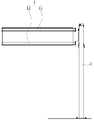
예컨대, 상기한 바와 같이 LED모듈이 내장된 교통표지판(1)은 도1에 도시된 바와 같이 내부에 수용공간이 형성되고 지주(2)에 설치되는 함체(11)와 이 함체(11)에 내부에 설치되는 복수의 LED모듈결합체(12), 및 LED모듈결합체(12)의 제어동작을 수행하는 제어장치(미도시)를 구비한 구조로 되어 있다.For example, as described above, the
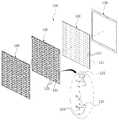
그리고, LED모듈 결합체(12)는 도2에 도시된 바와 같이 함체(11) 내부에 삽입되어 고정되는 모듈케이스(12a), 이 모듈케이스(12a)에 설치되고 인쇄회로기판상에 다수의 LED가 배열된 LED모듈(12b), LED모듈의 전면에 배치되는 투광렌즈(12c), 및 투광렌즈(12c)의 전면에 배치되고 태양광에 의한 광의 간섭을 방지하기 위한 선쉐이드부재(12d)로 구성되어 있다.And, the
아울러, 투광렌즈(12c)는 볼록렌즈 형태로 형성된 것으로, 도2의 확대 단면 부분에 나타난 바와 같이 평판 형상을 갖는 렌즈몸체(12c1)의 배면에 LED가 삽입되는 LED 삽입홈(12c2)이 요입되어 있다.In addition, the
하지만, 전술한 종래의 LED모듈결합체(12)는 볼록렌즈 형태로 형성된 투광렌즈(12c)가 설치되어 있어서 빛이 넓게 확산되므로 휘도가 균일하지 않아 교통표지장치에 적용할 경우 문자, 도안 등의 안내표시의 식별력이 떨어지고 시야각 좁은 단점이 있다.
However, the above-described conventional
본 발명은 상기 내용에 착안하여 제안된 것으로, 광원으로부터 발광되는 빛을 모아 휘도가 향상되도록 함으로써 안내표시의 식별력이 향상되고 시야각이 증가되도록 한 LED모듈결합체의 투광렌즈 및 이를 구비한 전광 교통표지판을 제공하는데 그 목적이 있다.
The present invention has been proposed in view of the above, by collecting the light emitted from the light source to improve the brightness to improve the identification of the guide display and to increase the viewing angle of the LED module assembly of the light-transmitting lens and the all-light traffic sign with the same The purpose is to provide.
상기 목적을 달성하기 위해, 본 발명에 따른 LED모듈결합체의 투광렌즈는 인쇄회로기판상에 다수의 LED가 배열된 LED모듈의 전면에 배치되는 LED모듈결합체의 투광렌즈에 있어서, 상기 투광렌즈는 평판형으로 형성된 투명 재질의 렌즈몸체; 상기 렌즈몸체의 저면에 상기 LED가 삽입, 안착되도록 요입되는 LED안착홈; 및 상기 LED안착홈과 대향되는 상기 렌즈몸체의 상면에 형성되는 투광부를 포함하고, 상기 투광부는 상기 렌즈몸체의 상면에 동심원 형태로 돌출되는 다수의 반사돌기를 포함하는 것을 특징으로 한다.In order to achieve the above object, the light transmitting lens of the LED module assembly according to the present invention is a light transmitting lens of the LED module assembly is arranged in front of the LED module is arranged a plurality of LEDs on a printed circuit board, the light transmitting lens is a flat plate Lens body made of a transparent material formed in the shape; An LED seating groove recessed to insert and seat the LED on the bottom surface of the lens body; And a light transmitting portion formed on an upper surface of the lens body facing the LED seating groove, wherein the light transmitting portion includes a plurality of reflecting protrusions protruding in a concentric shape on the upper surface of the lens body.
그리고, 상기 반사돌기의 돌출 높이와 두께는 핫스팟이 발생되지 않도록 상기 반사돌기 중 최외곽 반사돌기의 직경에 대해 1 내지 10% 범위의 치수를 갖도록 형성되고, 상기 반사돌기의 형성간격은 휘도를 고려하여 0.2 내지 1.5mm 범위의 간격을 갖도록 형성되며, 상기 반사돌기 중 최외곽 반사돌기의 직경은 상기 LED안착홈의 직경에 대해 100 내지 250% 범위의 직경을 갖도록 형성될 수 있다.The height and thickness of the protruding protrusions are formed to have a dimension in a range of 1 to 10% with respect to the diameter of the outermost protruding protrusion among the reflecting protrusions so that a hot spot does not occur. It is formed to have a distance in the range of 0.2 to 1.5mm, the diameter of the outermost reflecting projection of the reflecting projection may be formed to have a diameter of 100 to 250% range with respect to the diameter of the LED seating groove.
바람직하게, 상기 반사돌기의 돌출 높이와 두께는 2 내지 4mm 범위로 형성되고, 상기 반사돌기의 형성간격은 0.5 내지 1.0mm 범위로 형성된다.Preferably, the height and thickness of the protruding projections are formed in the range of 2 to 4 mm, and the formation interval of the reflective projections is formed in the range of 0.5 to 1.0 mm.
한편, 상기 목적을 달성하기 위해, 본 발명에 따른 LED모듈결합체의 투광렌즈를 구비한 전광 교통표지판은 전광 교통지판에 있어서, 함체와, 상기 함체에 설치되는 LED모듈결합체를 포함하되, 상기 LED모듈결합체는 상기한 투광렌즈가 구비된 것을 특징으로 한다.
On the other hand, in order to achieve the above object, the all-optical traffic sign provided with a light-transmitting lens of the LED module assembly according to the present invention, in the all-optical traffic signboard, including the enclosure and the LED module assembly installed in the enclosure, the LED module The combination is characterized in that the above-mentioned light transmitting lens.
본 발명에 따른 LED모듈결합체의 투광렌즈는 LED가 안착되는 부위에 해당되는 렌즈몸체에 동심원 형태로 돌출되는 다수의 반사돌기로 이루어진 투광부가 형성되어 발광되는 광을 모아 더 밝게 하므로 휘도가 향상됨에 따라 안내표시의 식별력이 향상되고 시야각이 넓어지는 효과가 있다.The light transmitting lens of the LED module assembly according to the present invention is formed on the lens body corresponding to the site on which the LED is seated is formed with a plurality of light projections projecting in a concentric circle formed in the condensed light to collect the light emitted to brighten the brightness is improved as The identification power of the guide display is improved and the viewing angle is widened.
그리고, 본 발명에 따른 투광렌즈가 구비된 LED모듈결합체를 이용하여 전광 교통표지판을 제작, 설치하게 되면, 휘도의 향상으로 안내표시의 식별력이 우수하므로 안전운행을 유도하여 교통사고를 줄일 수 있고, 교통 흐름을 원활하게 유지할 수 있을 뿐만 아니라 운전자 및 보행자에 편의성을 제공할 수 있다.
In addition, when manufacturing and installing an all-light traffic sign using the LED module assembly provided with a light-transmitting lens according to the present invention, it is possible to reduce traffic accidents by inducing safe driving because the identification of the guide display is excellent by improving the brightness. Not only can it keep traffic flowing smoothly, but it can also provide convenience for drivers and pedestrians.
도1은 종래 교통표지판을 설명하기 위한 도면,
도2는 종래 LED모듈결합체를 나타낸 분리사시도,
도3은 본 발명의 바람직한 실시예에 따른 투광렌즈가 구비되는 LED모듈결합체를 나타낸 분리사시도,
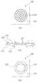
도4은 본 발명의 바람직한 실시예에 따른 LED모듈결합체의 투광렌즈의 요부를 나타낸 도면,
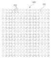
도5a는 본 발명의 바람직한 실시예에 따른 LED모듈결합체의 투광렌즈를 나타낸 정면도,
도5b는 본 발명의 바람직한 실시예에 따른 LED모듈결합체의 투광렌즈를 나타낸 배면도,
도6은 본 발명의 제1 실시예에 따른 LED모듈결합체의 투광렌즈를 나타낸 도면,
도7은 본 발명의 제2 실시예에 따른 LED모듈결합체의 투광렌즈를 나타낸 도면,
도8은 본 발명의 제3 실시예에 따른 LED모듈결합체의 투광렌즈를 나타낸 도면,
도9는 본 발명의 바람직한 실시예에 따른 LED모듈결합체의 투광렌즈를 구비한 전광 교통표지판을 설명하기 위한 사시도이다.1 is a view for explaining a conventional traffic sign,
Figure 2 is an exploded perspective view showing a conventional LED module assembly,
Figure 3 is an exploded perspective view showing the LED module assembly is provided with a light transmitting lens according to a preferred embodiment of the present invention,
4 is a view showing the main parts of a light transmitting lens of the LED module assembly according to a preferred embodiment of the present invention;
Figure 5a is a front view showing a light transmitting lens of the LED module assembly according to a preferred embodiment of the present invention,
Figure 5b is a rear view showing a light transmitting lens of the LED module assembly according to a preferred embodiment of the present invention,
6 is a view showing a light transmitting lens of the LED module assembly according to the first embodiment of the present invention;
7 is a view showing a light transmitting lens of the LED module assembly according to the second embodiment of the present invention;
8 is a view showing a light transmitting lens of the LED module assembly according to the third embodiment of the present invention;
9 is a perspective view illustrating an all-light traffic sign provided with a light transmitting lens of the LED module assembly according to a preferred embodiment of the present invention.
이하, 첨부된 도면을 참조하여 본 발명의 실시예를 구체적으로 설명한다.Hereinafter, embodiments of the present invention will be described in detail with reference to the accompanying drawings.
도3은 본 발명의 바람직한 실시예에 따른 투광렌즈가 구비되는 LED모듈결합체를 나타낸 분리사시도이다.Figure 3 is an exploded perspective view showing the LED module assembly is provided with a light transmitting lens according to a preferred embodiment of the present invention.
도3을 참조하면, LED모듈결합체(100)는 점등작용을 통해 운전자, 보행자 등에게 차량의 진행방향이나 제한속도 등을 알려주는 문자나 기호 등이 직접적으로 표현되는 부분으로 전광 교통표지판의 형태에 맞게 제작된 함체(200, 도9 참조)에 다수 개가 내장, 설치되도록 되어 있다.Referring to FIG. 3, the
그리고, LED모듈결합체(100)는 함체(200)에 마련된 모듈설치 프레임(210)에 설치되는 모듈하우징(110), 모듈하우징(110)에 설치되고 인쇄회로기판(121)상에 다수의 LED(122)가 배열된 램프모듈(120), 램프모듈(120)의 전면에 배치되고 광투과성 재질로 형성된 투광렌즈(130), 및 투광렌즈(130)의 전면에 배치되고 태양광에 의한 광의 간섭을 방지하기 위한 선쉐이드부재(140)로 구성되어 있다.In addition, the
그리고, 램프모듈(120)은 후면에 인가되는 제어신호에 따라 전면으로 문자, 기호 등이 영상으로 표현되도록 LED(122)의 구동을 제어하는 제어부(미도시)가 구비되어 있다.In addition, the
도4은 본 발명의 바람직한 실시예에 따른 LED모듈결합체의 투광렌즈의 요부를 나타낸 도면으로, (가)는 평면 구조를 나타낸 도면, (나)는 단면 구조를 나타낸 도면, (다)는 저면 구조를 나타낸 도면이다. 도5a는 본 발명의 바람직한 실시예에 따른 LED모듈결합체의 투광렌즈를 나타낸 정면도, 도5b는 본 발명의 바람직한 실시예에 따른 LED모듈결합체의 투광렌즈를 나타낸 배면도이다.4 is a view showing the main part of the light-transmitting lens of the LED module assembly according to a preferred embodiment of the present invention, (a) is a plan view, (b) a cross-sectional view, (c) a bottom structure The figure which shows. Figure 5a is a front view showing a light transmitting lens of the LED module assembly according to a preferred embodiment of the present invention, Figure 5b is a rear view showing a light transmitting lens of the LED module assembly according to a preferred embodiment of the present invention.
도4 및 도5b에 도시된 바와 같이 투광렌즈(130)는 평판형으로 형성된 투명 재질의 렌즈몸체(131), 이 렌즈몸체(131)의 저면에 LED(122)가 삽입, 안착되도록 요입되는 LED안착홈(132), 및 LED안착홈(132)과 대향되는 렌즈몸체(131)의 상면에 형성되는 투광부(133)를 구비한다.As shown in FIGS. 4 and 5B, the
그리고, 투광부(133)는 렌즈몸체(131)의 상면에 동심원 형태로 돌출되는 다수의 반사돌기(133a)로 구성된 점에 특징을 갖는 것으로 이하 구체적으로 설명한다.In addition, the
반사돌기(133a)의 돌출 높이(a)와 두께(b)는 반사돌기(133a) 중 최외곽 반사돌기의 직경에 대해 1% 미만이거나 10% 이상으로 형성할 경우에 핫스팟(hot spot,광의 조도 또는 휘도가 서로 달라서 발생되는 빛 자국)이 발생됨을 실험에 통해 확인할 수 있었다. 이에 따라, 반사돌기(133a)의 돌출 높이와 두께는 핫스팟(hot spot)이 발생되지 않도록 반사돌기(133a) 중 최외곽 반사돌기의 직경에 대해 1 내지 10% 범위로 형성한다. 특히, 반사돌기(133a)의 돌출 높이와 두께는 2 내지 4mm로 형성되는 것이 더욱 바람직하다.Protruding height (a) and thickness (b) of the reflecting projection (133a) is less than 1% or more than 10% of the diameter of the outermost reflecting projection of the reflecting projection (133a) when the hot spot (light spot) Alternatively, it could be confirmed through experiments that light marks generated due to different luminance are generated. Accordingly, the protruding height and thickness of the reflecting protrusion 133a may be formed in a range of 1 to 10% of the diameter of the outermost reflecting protrusion of the reflecting protrusion 133a so as not to generate a hot spot. In particular, the height and thickness of the protruding projections 133a are more preferably 2 to 4 mm.
그리고, 반사돌기(133a)는 그 형성간격(c)을 0.2mm 미만으로 조밀하게 형성하거나, 1.5mm 이상으로 넓게 형성할 경우 휘도가 급격하게 떨어짐을 실험을 통해 확인할 수 있었다. 이에 따라, 반사돌기(133a)의 형성간격은 휘도의 향상을 고려하여 0.2 내지 1.5mm 범위의 간격을 갖도록 형성한다. 특히, 반사돌기의 형성간격은 0.5 내지 1.0mm로 형성되는 것이 더욱 바람직하다.In addition, the reflection protrusion 133a can be confirmed through experiments that the formation interval c is densely formed to be less than 0.2mm, or when the formation is wider than 1.5mm. Accordingly, the formation intervals of the reflection protrusions 133a are formed to have an interval in the range of 0.2 to 1.5 mm in consideration of the improvement in luminance. In particular, it is more preferable that the forming interval of the reflecting protrusions is 0.5 to 1.0 mm.
또한 반사돌기(133a) 중 최외곽 반사돌기의 직경은 LED안착홈(132)의 직경에 대해 100 내지 250% 범위의 직경을 갖도록 형성될 수 있지만, 본 실시예에서는 이하에서 구체적으로 설명되는 바와 같이 LED를 교통표지판에 널리 사용되고 있는 통상적인 호칭규격 5050 SMD LED(SURFACE-MOUNT DEVICES LED,5450 SMD LED로도 호칭됨)를 적용함에 따라 그 규격치수(가로, 세로길이 5mm X 5mm)에 대해 200%의 직경인 10mm로 형성되어 있다.In addition, the diameter of the outermost reflecting projection of the reflecting projection 133a may be formed to have a diameter in the range of 100 to 250% with respect to the diameter of the
그리고, 투광렌즈(130)의 렌즈몸체(131)는 0.5mm 전후의 두께가 되도록 형성한다.The
이하, 본 발명에 따른 LED모듈결합체의 투광렌즈의 구체적인 실시예를 설명한다.Hereinafter, specific embodiments of the light transmitting lens of the LED module assembly according to the present invention.
도6은 본 발명의 제1 실시예에 따른 LED모듈결합체의 투광렌즈를 나타낸 도면이고, 도7은 본 발명의 제2 실시예에 따른 LED모듈결합체의 투광렌즈를 나타낸 도면이며, 도8은 본 발명의 제3 실시예에 따른 LED모듈결합체의 투광렌즈를 나타낸 도면이다. 그리고, 도6 내지 도8에서 (가)는 평면 구조를 나타낸 도면, (나)는 단면 구조를 나타낸 도면, (다)는 저면 구조를 나타낸 도면이다.6 is a view showing a light transmitting lens of the LED module assembly according to the first embodiment of the present invention, Figure 7 is a view showing a light transmitting lens of the LED module assembly according to the second embodiment of the present invention, Figure 8 3 is a view illustrating a light transmitting lens of the LED module assembly according to the third embodiment of the present invention. 6 to 8, (a) shows a planar structure, (b) shows a cross-sectional structure, and (c) shows a bottom structure.
<실시예1>≪ Example 1 >
도6을 참조하면, 본 발명의 제1 실시예에 따른 LED모듈결합체의 투광렌즈(130)는 반사돌기(133a)의 돌출 높이(a)와 두께(b)를 0.3mm로 형성하고 반사돌기(133a)의 형성간격(c)을 0.3mm로 형성하여 중심으로부터 8개의 반사돌기가 동심원 형태로 배치되게 형성하였다.Referring to FIG. 6, the
<실시예2>≪ Example 2 >
도7을 참조하면, 본 발명의 제2 실시예에 따른 LED모듈결합체의 투광렌즈(130)는 반사돌기(133a)의 돌출 높이(a)와 두께(b)를 0.3mm로 형성하고 반사돌기(133a)의 형성간격(c)을 0.5mm로 형성하여 중심으로부터 6개의 반사돌기가 동심원 형태로 배치되게 형성하였다.Referring to FIG. 7, the
<실시예3>≪ Example 3 >
도8을 참조하면, 본 발명의 제3 실시예에 따른 LED모듈결합체의 투광렌즈(130)는 반사돌기(133a)의 돌출 높이(a)와 두께(b)를 0.3mm로 형성하고 반사돌기(133a)의 형성간격(c)을 1.0mm로 형성하여 중심으로부터 4개의 반사돌기가 동심원을 이루도록 형성하였다.Referring to FIG. 8, the
한편, 전술한 각 실시예에서는 렌즈몸체(131)의 두께는 모두 0.5mm로 형성하고, LED안착홈(132)의 직경은 모두 7.8mm의 반경과 1mm의 깊이를 갖도록 형성하는 한편, LED안착홈(132)에 설치되는 LED는 모두 통상호칭 5050 SMD LED(가로, 세로길이 5mm X 5mm)를 적용한다.Meanwhile, in each of the above-described embodiments, the
그리고, 전술한 투광부(133)를 렌즈몸체(131)에 가로방향으로 4개씩 4열을 이루도록 등간격으로 형성하고, 그 배면에 LED안착홈(132)과 대응되게 인쇄회로기판상에 LED가 배치된 LED모듈(120)을 설치하여 LED모듈결합체(100)를 구성한다.Then, the above-described
이때, LED는 화이트(White)LED, 레드(Red)LED, 그린(Green)LED, 블루(Blue)LED를 적용하여 각 실시예 마다 4개씩의 LED모듈결합체(100)를 제작한다.At this time, the LED is applied to the white LED, red (Red) LED, Green (Green), Blue (Blue) LED to produce four
이후 제1 내지 제3 실시예에 따른 12개의 LED모듈결합체(100)를 암실에 순서대로 설치하고 전원을 공급하여 점등시킨 다음 LED모듈결합체로부터 10미터(m)의 거리에 조도측정기 측정모듈을 배치하여 조도를 측정하였다.Thereafter, the twelve
표1은 전술한 제1 내지 제3 실시예에 의해 제작된 LED모듈결합체의 조도 및 휘도를 측정하여 표시한 것이다.Table 1 shows the measured and displayed illuminance and luminance of the LED module assembly produced by the first to third embodiments described above.
아울러, 반사돌기(133a)의 형성간격(c)을 0.2mm 미만으로 조밀하게 형성하거나, 1.5mm 이상으로 넓게 형성한 투광렌즈가 구비된 LED모듈결합체를 제작하여 동일한 방법으로 조도를 측정한 결과, 표1에 나타난 제1 내지 제3 실시예에 비해 조도 및 휘도가 급격하게 저하됨을 확인할 수 있었다. 비교예로서 구체적인 설명과 비교는 생략한다.In addition, as a result of measuring the roughness in the same manner by forming the LED module assembly with a transparent lens formed in the formation gap (c) of the reflective projection 133a less than 0.2mm densely, or wider than 1.5mm, As compared with the first to third embodiments shown in Table 1, it was confirmed that the illuminance and luminance sharply decreased. As a comparative example, detailed description and comparison are abbreviate | omitted.
표1에 나타난 바와 같이 반사돌기(133a)의 형성간격(c)은 LED모듈결합체의 조도 및 휘도에 중요한 인자임을 확인할 수 있다. 즉, 특정 색상(레드(Red)LED, 블루(Blue)LED)의 LED에서는 미차가 있었으나 전반적으로 반사돌기(133a)의 형성간격(c)을 0.3mm로 형성한 제1 실시예, 반사돌기(133a)의 형성간격(c)을 0.5mm로 형성한 제2 실시예, 반사돌기(133a)의 형성간격(c)을 1.0mm로 형성한 제3 실시예 순으로 조도 및 휘도 특성이 우수함을 확인할 수 있었고, 반사돌기(133a)의 형성간격이 제1 내지 제3 실시예를 벗어날 경우 조도 및 휘도 특성이 저하됨을 확인할 수 있었다.As shown in Table 1, it can be seen that the formation interval c of the reflection protrusion 133a is an important factor for the illuminance and luminance of the LED module assembly. That is, in the LED of a specific color (red LED, blue LED), although there is a difference, the first embodiment in which the formation gap c of the reflection protrusion 133a is formed to be 0.3 mm, the reflection protrusion ( The second embodiment in which the formation interval c of the 133a was formed to 0.5 mm and the third embodiment in which the formation interval c of the reflective protrusion 133a was 1.0 mm were confirmed to have excellent illuminance and luminance characteristics. It was able to confirm that the illumination intensity and luminance characteristics are deteriorated when the formation interval of the reflection protrusion 133a deviates from the first to third embodiments.
그리고, 표1에 표시된 휘도는 조도측정기에 의해 측정된 각 실시예에 따른 LED모듈결합체의 조도(lx)를 휘도(cd/㎡)로 환산한 것으로, 통상적인 환산식(cd/㎡= X(lx) x 0.94(통상 Mirror 반사율) x 0.75(통상 Screen의 투과율) x 5.7(현재 사용중인 Screen(Toppan, DNP)gain) x 0.318(lx에서 nit로의 변환계수)에 의해 환산하여 표시하였다.In addition, the luminance shown in Table 1 is obtained by converting the illuminance (lx) of the LED module assembly according to each embodiment measured by the illuminance measuring instrument into the luminance (cd / m 2), and the conventional conversion equation (cd /
도9는 본 발명의 바람직한 실시예에 따른 LED모듈결합체의 투광렌즈를 구비한 전광 교통표지판을 설명하기 위한 사시도이다.9 is a perspective view illustrating an all-light traffic sign provided with a light transmitting lens of the LED module assembly according to a preferred embodiment of the present invention.
도9를 참조하면, 본 발명에 따른 LED모듈결합체의 투광렌즈를 구비한 전광 교통표지판은 함체(200)와, 이 함체(200)에 설치되는 LED모듈결합체(100)를 구비하되, LED모듈결합체(100)는 전술한 투광렌즈(130)가 구비된 것을 적용하여 구성한다.9, the all-optical traffic sign provided with a light transmitting lens of the LED module assembly according to the present invention includes a
그리고, 함체(200)는 전체적인 골격을 형성하는 부분으로 전면방향에 상기한 LED모듈 결합체(100)가 설치되고 내부에 수용공간이 형성된 것으로, 수용공간의 내부 또는 함체(200)의 외면에는 전광 교통표시판을 지주에 설치하기 위한 횡지지대(미도시)가 결합되도록 되어 있다.In addition, the
전술한 바와 같이 구성된 전광 교통표지판은 휘도 특성이 우수한 투광렌즈(130)가 구비된 LED모듈결합체(100)가 설치되어 있으므로 빛이 넓게 확산되지 않고 휘도가 균일하여 안내표시의 식별력이 우수하고 시야각이 넓어지게 되는 효과를 발휘한다.The all-optical traffic sign plate configured as described above has the
이상에서 설명한 것은 본 발명에 따른 LED모듈결합체의 투광렌즈 및 이를 구비한 전광 교통표지판을 실시하기 위한 하나의 실시예에 불과한 것으로서, 본 발명은 상기한 실시예에 한정되지 않고, 이하의 특허청구범위에서 청구하는 바와 같이 본 발명의 요지를 벗어나지 않은 범위 내에서 당해 발명이 속하는 분야에서 통상의 지식을 가진 자라면 누구든지 다양한 변경실시가 가능한 범위까지 본 발명의 기술적 사상이 있다고 할 것이다.
What has been described above is only one embodiment for implementing the light-transmitting lens of the LED module assembly according to the present invention and the all-optical traffic sign provided with the same, the present invention is not limited to the above-described embodiment, the following claims As claimed in the present invention, those skilled in the art to which the present invention pertains without departing from the gist of the present invention will have the technical idea of the present invention to the extent that various modifications can be made.
100:LED모듈결합체 110:모듈하우징
120:램프모듈 121:인쇄회로기판
122:LED 130:투광렌즈
131:렌즈몸체 132:LED안착홈
133:투광부 133a:반사돌기
140:선쉐이드부재 200:함체
210:모듈설치 프레임 a:반사돌기의 돌출 높이
b:반사돌기의 두께 c:반사돌기의 형성간격100: LED module assembly 110: module housing
120: lamp module 121: printed circuit board
122: LED 130: transmissive lens
131: lens body 132: LED seating groove
133: light transmitting part 133a: reflector
140: sunshade member 200: enclosure
210: module mounting frame a: height of the projection projection
b: Thickness of the reflector c: Formation interval of the reflector
Claims (4)
Translated fromKorean상기 투광렌즈는 평판형으로 형성된 투명 재질의 렌즈몸체; 상기 렌즈몸체의 저면에 상기 LED가 삽입, 안착되도록 요입되는 LED안착홈; 및 상기 LED안착홈과 대향되는 상기 렌즈몸체의 상면에 형성되는 투광부를 포함하고, 상기 투광부는 상기 렌즈몸체의 상면에 동심원 형태로 돌출되는 다수의 반사돌기를 포함하되,
상기 반사돌기의 돌출 높이와 두께는 핫스팟이 발생되지 않도록 상기 반사돌기 중 최외곽 반사돌기의 직경에 대해 1 내지 10% 범위의 치수를 갖도록 형성되고,
상기 반사돌기의 형성간격은 휘도를 고려하여 0.2 내지 1.5mm 범위의 간격을 갖도록 형성되며,
상기 반사돌기 중 최외곽 반사돌기의 직경은 상기 LED안착홈의 직경에 대해 100 내지 250% 범위의 직경을 갖도록 형성된 것을 특징으로 하는 LED모듈결합체의 투광렌즈.
In the light transmitting lens of the LED module assembly is arranged in front of the LED module in which a plurality of LEDs are arranged on a printed circuit board,
The light transmitting lens is a lens body of a transparent material formed in a flat plate shape; An LED seating groove recessed to insert and seat the LED on the bottom surface of the lens body; And a light transmitting portion formed on an upper surface of the lens body opposite the LED seating groove, wherein the light transmitting portion includes a plurality of reflective protrusions protruding in an upper surface of the lens body in a concentric manner.
Protruding height and thickness of the reflective projections are formed to have a dimension in the range of 1 to 10% with respect to the diameter of the outermost reflective projections of the reflective projections so that hot spots do not occur,
Forming interval of the reflective projections are formed to have an interval of 0.2 to 1.5mm in consideration of the brightness,
The projection lens of the LED module assembly, characterized in that the diameter of the outermost reflecting projection of the reflecting projection is formed to have a diameter in the range of 100 to 250% with respect to the diameter of the LED seating groove.
상기 반사돌기의 돌출 높이와 두께는 2 내지 4mm이고,
상기 반사돌기의 형성간격은 0.5 내지 1.0mm인 것을 특징으로 하는 LED모듈결합체의 투광렌즈.
The method of claim 1,
Protruding height and thickness of the reflective projections is 2 to 4mm,
Forming interval of the reflective projection is a light transmitting lens of the LED module assembly, characterized in that 0.5 to 1.0mm.
함체와;
상기 함체에 설치되는 LED모듈결합체를 포함하되,
상기 LED모듈결합체는 제1항 또는 제3항의 투광렌즈가 구비된 것을 특징으로 하는 LED모듈결합체의 투광렌즈를 구비한 전광 교통표지판.
For all-optical traffic signs,
A housing and;
Including LED module assembly is installed in the housing,
The LED module assembly is an all-optical traffic sign provided with a light-transmitting lens of the LED module assembly, characterized in that the projection lens of claim 1 or 3.
Priority Applications (1)
| Application Number | Priority Date | Filing Date | Title |
|---|---|---|---|
| KR1020120069548AKR101373600B1 (en) | 2012-06-28 | 2012-06-28 | Transparent lens of led module assembly and apparatus for displaying traffic information using it |
Applications Claiming Priority (1)
| Application Number | Priority Date | Filing Date | Title |
|---|---|---|---|
| KR1020120069548AKR101373600B1 (en) | 2012-06-28 | 2012-06-28 | Transparent lens of led module assembly and apparatus for displaying traffic information using it |
Publications (2)
| Publication Number | Publication Date |
|---|---|
| KR20140006224A KR20140006224A (en) | 2014-01-16 |
| KR101373600B1true KR101373600B1 (en) | 2014-03-12 |
Family
ID=50141191
Family Applications (1)
| Application Number | Title | Priority Date | Filing Date |
|---|---|---|---|
| KR1020120069548AExpired - Fee RelatedKR101373600B1 (en) | 2012-06-28 | 2012-06-28 | Transparent lens of led module assembly and apparatus for displaying traffic information using it |
Country Status (1)
| Country | Link |
|---|---|
| KR (1) | KR101373600B1 (en) |
Cited By (1)
| Publication number | Priority date | Publication date | Assignee | Title |
|---|---|---|---|---|
| KR101943836B1 (en) | 2018-07-17 | 2019-01-30 | 문승호 | The Direct-type surface light source device |
Families Citing this family (2)
| Publication number | Priority date | Publication date | Assignee | Title |
|---|---|---|---|---|
| KR102027087B1 (en)* | 2019-03-28 | 2019-11-04 | 주식회사 카이넥스엠 | Changeable sign board device for double sealing structure |
| KR102274013B1 (en) | 2021-02-09 | 2021-07-08 | 진재언 | Module for LED Electric Light Board with Improved Waterproofing Property |
Citations (3)
| Publication number | Priority date | Publication date | Assignee | Title |
|---|---|---|---|---|
| JP2006344409A (en) | 2005-06-07 | 2006-12-21 | Seiko Instruments Inc | Light fixture, and display device provided with the same |
| JP2009158473A (en)* | 2007-12-05 | 2009-07-16 | First System Co Ltd | Lighting device |
| KR20110134439A (en)* | 2009-04-03 | 2011-12-14 | 샤프 가부시키가이샤 | Lighting devices, display devices and television receivers |
- 2012
- 2012-06-28KRKR1020120069548Apatent/KR101373600B1/ennot_activeExpired - Fee Related
Patent Citations (3)
| Publication number | Priority date | Publication date | Assignee | Title |
|---|---|---|---|---|
| JP2006344409A (en) | 2005-06-07 | 2006-12-21 | Seiko Instruments Inc | Light fixture, and display device provided with the same |
| JP2009158473A (en)* | 2007-12-05 | 2009-07-16 | First System Co Ltd | Lighting device |
| KR20110134439A (en)* | 2009-04-03 | 2011-12-14 | 샤프 가부시키가이샤 | Lighting devices, display devices and television receivers |
Cited By (1)
| Publication number | Priority date | Publication date | Assignee | Title |
|---|---|---|---|---|
| KR101943836B1 (en) | 2018-07-17 | 2019-01-30 | 문승호 | The Direct-type surface light source device |
Also Published As
| Publication number | Publication date |
|---|---|
| KR20140006224A (en) | 2014-01-16 |
Similar Documents
| Publication | Publication Date | Title |
|---|---|---|
| US8007127B2 (en) | Lens for LED outdoor lamp, and its applied road lamp, security lamp, tunnel lamp, park lamp, guard lamp, industrial flood lamp, and outdoor lamp | |
| CN106996535B (en) | Lighting or signal optical unit for a motor vehicle comprising an opalescence mask | |
| US20140338237A1 (en) | Vehicle sign display employing semiconductor lighting elements | |
| JP2022504564A (en) | Car light module | |
| KR101373600B1 (en) | Transparent lens of led module assembly and apparatus for displaying traffic information using it | |
| TWI624387B (en) | Embedded led assembly with optional beam steering optical element, associated products, and methods | |
| KR102287384B1 (en) | attention-grabbing advertising device | |
| KR101108102B1 (en) | LED warning light | |
| KR200448173Y1 (en) | Road signing device | |
| EP3002745B1 (en) | Interior aircraft light unit | |
| KR101238717B1 (en) | Display device | |
| CN222713394U (en) | Interactive screen and transportation tool | |
| KR20160104117A (en) | traffic signal board | |
| KR20080095591A (en) | Double lighted LED luminaire | |
| KR102616507B1 (en) | Inner bumper projection system for automabiles using unit solid state surface light source and meta-mirror(multi-mirror cells) | |
| CN214152303U (en) | Electronic guideboard | |
| KR20210016906A (en) | Road sign board using light guide plate having improved visibility | |
| US12241610B2 (en) | Lighting device for a motor vehicle | |
| CN212719409U (en) | Diffusion plate and direct type panel lamp | |
| CN215944426U (en) | Interactive locomotive and unmanned vehicle | |
| CN218209368U (en) | Large-angle luminous chassis lamp | |
| EP2803911B1 (en) | Led lighting device with improved light distribution | |
| CN211468163U (en) | Low-power consumption vehicle instrument panel | |
| ES2262398B1 (en) | LIGHTING SIGNAL SCREEN. | |
| JP2010026863A (en) | Led display device and traffic light for pedestrian |
Legal Events
| Date | Code | Title | Description |
|---|---|---|---|
| A201 | Request for examination | ||
| PA0109 | Patent application | St.27 status event code:A-0-1-A10-A12-nap-PA0109 | |
| PA0201 | Request for examination | St.27 status event code:A-1-2-D10-D11-exm-PA0201 | |
| P11-X000 | Amendment of application requested | St.27 status event code:A-2-2-P10-P11-nap-X000 | |
| P13-X000 | Application amended | St.27 status event code:A-2-2-P10-P13-nap-X000 | |
| N231 | Notification of change of applicant | ||
| PN2301 | Change of applicant | St.27 status event code:A-3-3-R10-R13-asn-PN2301 St.27 status event code:A-3-3-R10-R11-asn-PN2301 | |
| N231 | Notification of change of applicant | ||
| PN2301 | Change of applicant | St.27 status event code:A-3-3-R10-R13-asn-PN2301 St.27 status event code:A-3-3-R10-R11-asn-PN2301 | |
| E902 | Notification of reason for refusal | ||
| PE0902 | Notice of grounds for rejection | St.27 status event code:A-1-2-D10-D21-exm-PE0902 | |
| E13-X000 | Pre-grant limitation requested | St.27 status event code:A-2-3-E10-E13-lim-X000 | |
| P11-X000 | Amendment of application requested | St.27 status event code:A-2-2-P10-P11-nap-X000 | |
| P13-X000 | Application amended | St.27 status event code:A-2-2-P10-P13-nap-X000 | |
| PG1501 | Laying open of application | St.27 status event code:A-1-1-Q10-Q12-nap-PG1501 | |
| E701 | Decision to grant or registration of patent right | ||
| PE0701 | Decision of registration | St.27 status event code:A-1-2-D10-D22-exm-PE0701 | |
| GRNT | Written decision to grant | ||
| PR0701 | Registration of establishment | St.27 status event code:A-2-4-F10-F11-exm-PR0701 | |
| PR1002 | Payment of registration fee | St.27 status event code:A-2-2-U10-U11-oth-PR1002 Fee payment year number:1 | |
| PG1601 | Publication of registration | St.27 status event code:A-4-4-Q10-Q13-nap-PG1601 | |
| PN2301 | Change of applicant | St.27 status event code:A-5-5-R10-R11-asn-PN2301 | |
| PN2301 | Change of applicant | St.27 status event code:A-5-5-R10-R14-asn-PN2301 | |
| P14-X000 | Amendment of ip right document requested | St.27 status event code:A-5-5-P10-P14-nap-X000 | |
| P16-X000 | Ip right document amended | St.27 status event code:A-5-5-P10-P16-nap-X000 | |
| Q16-X000 | A copy of ip right certificate issued | St.27 status event code:A-4-4-Q10-Q16-nap-X000 | |
| PN2301 | Change of applicant | St.27 status event code:A-5-5-R10-R13-asn-PN2301 St.27 status event code:A-5-5-R10-R11-asn-PN2301 | |
| FPAY | Annual fee payment | Payment date:20170302 Year of fee payment:4 | |
| PR1001 | Payment of annual fee | St.27 status event code:A-4-4-U10-U11-oth-PR1001 Fee payment year number:4 | |
| LAPS | Lapse due to unpaid annual fee | ||
| PC1903 | Unpaid annual fee | St.27 status event code:A-4-4-U10-U13-oth-PC1903 Not in force date:20180307 Payment event data comment text:Termination Category : DEFAULT_OF_REGISTRATION_FEE | |
| PC1903 | Unpaid annual fee | St.27 status event code:N-4-6-H10-H13-oth-PC1903 Ip right cessation event data comment text:Termination Category : DEFAULT_OF_REGISTRATION_FEE Not in force date:20180307 | |
| P22-X000 | Classification modified | St.27 status event code:A-4-4-P10-P22-nap-X000 | |
| P22-X000 | Classification modified | St.27 status event code:A-4-4-P10-P22-nap-X000 | |
| P22-X000 | Classification modified | St.27 status event code:A-4-4-P10-P22-nap-X000 |