KR101371211B1 - Scanner for oral cavity - Google Patents
Scanner for oral cavityDownload PDFInfo
- Publication number
- KR101371211B1 KR101371211B1KR1020130081775AKR20130081775AKR101371211B1KR 101371211 B1KR101371211 B1KR 101371211B1KR 1020130081775 AKR1020130081775 AKR 1020130081775AKR 20130081775 AKR20130081775 AKR 20130081775AKR 101371211 B1KR101371211 B1KR 101371211B1
- Authority
- KR
- South Korea
- Prior art keywords
- scanner
- unit
- light
- light output
- reflector
- Prior art date
- Legal status (The legal status is an assumption and is not a legal conclusion. Google has not performed a legal analysis and makes no representation as to the accuracy of the status listed.)
- Expired - Fee Related
Links
Images


Classifications
- A—HUMAN NECESSITIES
- A61—MEDICAL OR VETERINARY SCIENCE; HYGIENE
- A61B—DIAGNOSIS; SURGERY; IDENTIFICATION
- A61B5/00—Measuring for diagnostic purposes; Identification of persons
- A61B5/0059—Measuring for diagnostic purposes; Identification of persons using light, e.g. diagnosis by transillumination, diascopy, fluorescence
- A61B5/0082—Measuring for diagnostic purposes; Identification of persons using light, e.g. diagnosis by transillumination, diascopy, fluorescence adapted for particular medical purposes
- A61B5/0088—Measuring for diagnostic purposes; Identification of persons using light, e.g. diagnosis by transillumination, diascopy, fluorescence adapted for particular medical purposes for oral or dental tissue
- A—HUMAN NECESSITIES
- A61—MEDICAL OR VETERINARY SCIENCE; HYGIENE
- A61B—DIAGNOSIS; SURGERY; IDENTIFICATION
- A61B5/00—Measuring for diagnostic purposes; Identification of persons
- A61B5/0059—Measuring for diagnostic purposes; Identification of persons using light, e.g. diagnosis by transillumination, diascopy, fluorescence
- A61B5/0062—Arrangements for scanning
- A—HUMAN NECESSITIES
- A61—MEDICAL OR VETERINARY SCIENCE; HYGIENE
- A61C—DENTISTRY; APPARATUS OR METHODS FOR ORAL OR DENTAL HYGIENE
- A61C19/00—Dental auxiliary appliances
- A61C19/04—Measuring instruments specially adapted for dentistry
- G—PHYSICS
- G06—COMPUTING OR CALCULATING; COUNTING
- G06T—IMAGE DATA PROCESSING OR GENERATION, IN GENERAL
- G06T11/00—2D [Two Dimensional] image generation
Landscapes
- Health & Medical Sciences (AREA)
- Life Sciences & Earth Sciences (AREA)
- Engineering & Computer Science (AREA)
- Public Health (AREA)
- Biomedical Technology (AREA)
- Biophysics (AREA)
- Physics & Mathematics (AREA)
- Veterinary Medicine (AREA)
- Animal Behavior & Ethology (AREA)
- General Health & Medical Sciences (AREA)
- Dentistry (AREA)
- Molecular Biology (AREA)
- Oral & Maxillofacial Surgery (AREA)
- Surgery (AREA)
- Medical Informatics (AREA)
- Heart & Thoracic Surgery (AREA)
- Pathology (AREA)
- Radiology & Medical Imaging (AREA)
- Nuclear Medicine, Radiotherapy & Molecular Imaging (AREA)
- Theoretical Computer Science (AREA)
- Epidemiology (AREA)
- General Physics & Mathematics (AREA)
- Audiology, Speech & Language Pathology (AREA)
- Dental Tools And Instruments Or Auxiliary Dental Instruments (AREA)
Abstract
Translated fromKoreanDescription
Translated fromKorean본 발명은 치과 환자의 구강 내부에 삽입되어 다수의 치아, 치은조직 및 보철물에 대한 정확한 스캐닝 정보를 획득하고, 상기 정보를 이용하여 치과 치료에 이용할 수 있는 구강용 스캐너에 관한 것이다.
The present invention relates to an oral scanner that can be inserted into the oral cavity of a dental patient to obtain accurate scanning information for a plurality of teeth, gingival tissue and prostheses, and can be used for dental treatment using the information.
일반적으로 치과 병원 등에서는 인체 구강내에 적용되는 보철물을 제작하기 위해서는 통상적으로 구강내를 본떠(Impression)서 석고모델(Master Model)을 만들고, 상기 석고모델을 기준으로 보철물을 만들었으며 상기 석고모델을 몰드로 이용한 제작법은 전통적이고 오랜 시간 동안 진행되어 왔기에 신뢰성과 표준화가 잘되어 있으나, 인상 과정의 오차와 인상재의 혼수비를 맞추는 것이 까다롭고, 온도와 습도 등에 따라 인상재의 경화시간이 달라지는 등 일관된 결과를 기대하기 어려운 점이 있었다.In general, in order to manufacture a prosthesis applied to the oral cavity of a human body, a dental model is generally made of a plaster model (Master Model) by imitation of the oral cavity, and a prosthesis is made based on the plaster model, and the plaster model is molded. The fabrication method used is traditional and has been progressed for a long time, so it is reliable and standardized, but it is difficult to match the error of the impression process and the coma ratio of the impression material, and the curing time of the impression material varies depending on temperature and humidity. There was something difficult to expect.
또한, 실리콘 인상재와 같이 일정한 인상경화조건을 발현하는 재료는 가격이 비싸서 환자의 비용부담이 커지는 단점이 있고, 인상재를 구강내에서 경화 후 탈거하는 과정에서 잘 빠지지 않는 불편함이 있었다.In addition, a material expressing a constant impression hardening condition, such as a silicone impression material has a disadvantage that the cost burden of the patient is increased due to the high price, there is an inconvenience that does not fall well in the process of removing the impression material after curing in the oral cavity.
이와 같이 재료의 지속적 소비와 일관되지 않은 결과, 적용상의 불편을 해소하기 위해 광학장비를 이용하여 구강내의 3차원 환경을 직접 취득하는 방법이 고안되었다.As a result of inconsistent with continuous consumption of materials, a method of directly acquiring a three-dimensional environment in the oral cavity using optical equipment has been devised to solve application inconveniences.
이를 위해 프로젝터를 광원으로 하여 구강내에 조사하고, 이를 카메라로 취득하여 3각법을 이용하여 3차원 데이터로 변환하는 방법이 적용되었으나, 프로젝터를 이용한 광원은 음영대와 양영대 간의 광구배(Light Gradient)의 선예도가 높지 않고, 거리에 따라 빛 번짐이 심해 정밀도를 높이는 데에 한계가 있어 왔다.For this purpose, the projector is used as a light source to irradiate the oral cavity, which is acquired by a camera, and converted into three-dimensional data by using a triangular method. The sharpness of is not high and there is a limit to increase the precision due to the light blurring with distance.
또한 종래의 구강 내 상태를 파악하기 위해 널리 사용되고 있는 방식으로는 시트 형상의 필름을 구강 내로 삽입시켜 환자의 손 또는 혀를 이용하여 필름을 환부 근처에 고정한 다음, 엑스레이와 같은 방사선을 구강의 환부에 투사하고 이에 근거한 필름을 이용하는 방식이 제안되고 있다.In addition, the method widely used to determine the state of the oral cavity is a sheet-like film is inserted into the oral cavity to fix the film near the affected area using the patient's hand or tongue, and then radiation such as x-rays to the affected area of the oral cavity A method of projecting and using film based thereon has been proposed.
그러나, 이러한 방식은 방사선 사진을 이용하여 2차원적으로 수작업을 하여 계측하거나 혹은 CT사진(computer tomography)에 의존함으로써, 3차원적 구조물을 2차원적 평면 계측하는 과정에서 오류가 발생될 수 있는 문제점이 있다. 또한, 환자에게 많은 양의 방사선 조사를 받게 하고, 환자의 경제적인 부담과 시행 단계에서의 복잡성 등으로 많은 임상적 문제점을 야기할 수 있다. 따라서, 환자의 건강 상에 문제를 일으킬 가능성이 적으면서도 치아를 정확하게 3차원 모델링할 수 있는 구강용 스캐너가 필요한 실정이다.
However, this method may cause errors in the process of two-dimensional plane measurement of a three-dimensional structure by performing manual measurement in two dimensions using a radiograph or relying on computer tomography. There is this. In addition, the patient may be exposed to a large amount of radiation, and the patient's economic burden and complexity at the implementation stage may cause many clinical problems. Therefore, there is a need for an oral scanner capable of accurately three-dimensional modeling of teeth while having a low possibility of causing a problem in a patient's health.
본 발명의 실시 예들은 환자의 구강 내부에 배치된 치아, 치은조직, 보철물에 대한 스캐닝 작업을 보다 편리하고 효율적으로 실시함과 동시에 데이터 취득 중 구강용 스캐너의 이동에 따른 데이터 오류를 최소화시켜 보다 정확한 환자의 치아에 대한 스캐닝 정보를 획득하고자 한다.
Embodiments of the present invention are more convenient and efficient scanning of teeth, gingival tissue, and prostheses disposed inside the oral cavity of the patient and at the same time to minimize the data errors caused by movement of the oral scanner during data acquisition more accurate To obtain scanning information about the teeth of the patient.
본 발명의 일 측면에 따르면, 레이저 광원이 조사되는 광 출력부; 상기 광 출력부로부터 출력된 출력광을 서로 다른 시간 동안 서로 다른 위상으로 변환시키는 위상 변동부; 상기 위상 변동부의 이동에 따른 위치 또는 상태 정보를 검출하는 위상 검출부; 상기 광 출력부와 서로 마주보며 배치되고 상기 광 출력부에서 조사된 광을 굴절시키는 제1 반사부; 상기 제1 반사부와 마주보며 배치되고, 상기 제1 반사부를 통해 반사된 광을 환자의 구강에 배치된 피측정 대상물을 향해 반사시키는 제2 반사부; 상기 제1 반사부의 후방에 배치되어 상기 피측정 대상물에서 반사된 반사광을 입력받아 2차원 영상 정보로 변환하는 영상 정보 취득부; 및 상기 피측정 대상물에 대한 데이터를 취득하는 동안 가속도 변화를 감지하는 가속도 감지부를 포함한다.According to an aspect of the invention, the light output unit is irradiated with a laser light source; A phase shifter for converting output light output from the light output part into different phases for different times; A phase detector for detecting position or state information according to the movement of the phase shifter; A first reflector disposed to face the light output unit and refracting light emitted from the light output unit; A second reflector disposed to face the first reflector and reflecting light reflected through the first reflector toward an object to be measured disposed in a mouth of a patient; An image information acquisition unit disposed behind the first reflector and configured to receive reflected light reflected from the object to be measured and convert the received light into two-dimensional image information; And an acceleration sensing unit that senses an acceleration change while acquiring data on the object to be measured.
상기 광 출력부는 레이저 광이 발생되는 광 발생부; 상기 광 발생부의 상면에 설치되고 라인 형태로 레이저 광을 제1 반사부로 조사하기 위한 광학 위상 변화부를 포함한다.The light output unit includes a light generating unit for generating laser light; It is provided on the upper surface of the light generating unit and includes an optical phase change unit for irradiating the laser light to the first reflecting unit in the form of a line.
상기 제1 반사부는 증착 코팅된 평면유리 또는 증착 코팅된 직각프리즘 또는 증착 코팅된 접합프리즘 중의 어느 하나가 선택적으로 사용되는 것을 특징으로 한다.The first reflector may be any one of a deposition coated flat glass, a deposition coated right angle prism, or a deposition coated bonding prism.
상기 제1 반사부는 반투과 타입의 프리즘 또는 유리 중의 어느 하나가 선택적으로 사용되는 것을 특징으로 한다.The first reflector is characterized in that any one of the transflective prism or glass is selectively used.
상기 제1 반사부는 가로 길이와 세로 길이와 각각 동일 길이로 이루어진 것을 특징으로 한다.The first reflector may be formed of the same length as each of the horizontal length and the vertical length.
상기 위상 변동부는 전기와 자석 사이에서 발생된 전자기력을 통해 회전 또는 직선 이동력을 전달받아 상기 광 출력부가 안착된 안착부를 왕복 동시키는 이동부를 포함한다.The phase shift part includes a moving part which receives a rotational or linear movement force through an electromagnetic force generated between electricity and a magnet and reciprocates a seating part on which the light output part is seated.
상기 위상 변동부는 전기와 자석 사이에서 발생된 전자기력을 통해 회전력을 전달받아 상기 광 출력부가 안착된 안착부를 회전 이동시키는 이동부를 포함한다.The phase shift unit includes a moving unit which receives a rotational force through an electromagnetic force generated between electricity and a magnet to rotate the seating unit on which the light output unit is mounted.
상기 위상 변동부는 모터에서 발생된 회전력을 전달받아 상기 광 출력부를 정 위치에서 회전 이동시키는 회전축을 포함한다.The phase shift unit includes a rotation shaft that receives the rotational force generated from the motor and rotates the light output unit at a fixed position.
상기 구강용 스캐너는 상기 안착부의 안정적인 이동을 가이드 하는 가이드부를 포함한다.The oral scanner includes a guide part for guiding stable movement of the seating part.
상기 위상 변동부는 모터에서 발생된 회전력을 전달받아 상기 광 출력부를 정 위치에서 회전 이동시키기 위해 상기 광 출력부의 외측에 권취된 벨트; 상기 광 출력부의 외측을 향해 연장되고 상기 광 출력부가 벨트에 의해 회전되는 동안 정 위치에서 회전되기 위해 구비된 회전축을 포함한다.The phase shift unit may receive a rotational force generated from a motor and a belt wound around the light output unit to rotate the light output unit at a fixed position; And a rotation axis provided to extend outwardly of the light output part and to rotate in a fixed position while the light output part is rotated by a belt.
상기 제2 반사부는 상기 제1 반사부를 통해 조사된 광을 완전 반사시켜 상기 피측정 대상물로 굴절시키는 것을 특징으로 한다.The second reflector may be configured to completely reflect light irradiated through the first reflector to refracted to the object to be measured.
상기 구강용 스캐너는 상기 영상 정보 취득부와 위상 검출부로부터 전송된 데이터를 연산하여 복수개의 3차원 데이터를 생성하고, 상기 3차원 데이터를 가속도 감지부를 통해 전송된 데이터를 이용하여 정합함으로써 환자의 피측정 대상물에 대한 스캐닝 모델을 생성하는 것을 특징으로 한다.The oral scanner generates a plurality of 3D data by calculating the data transmitted from the image information acquisition unit and the phase detection unit, and matches the 3D data using the data transmitted through the acceleration detection unit to measure the patient's blood. And generating a scanning model for the object.
상기 구강용 스캐너는 시술자가 손으로 파지되는 스캐너 본체; 상기 스캐너 본체의 전방에 설치되고 선단부에 상기 제2 반사부가 설치되어 환자의 구강 내측으로 삽입되는 삽입체를 포함한다.The oral scanner includes a scanner body in which the operator grips the hand; It includes an insert which is installed in front of the scanner body and the second reflecting portion is installed at the front end and inserted into the mouth of the patient.
상기 삽입체는 상기 스캐너 본체와 선택적으로 착탈 가능하게 결합되는 것을 특징으로 한다.The insert may be selectively detachably coupled to the scanner body.
상기 삽입체는 상기 스캐너 본체에 결합된 상태로 길이 방향을 축으로 상대 회전되는 것을 특징으로 한다.
The insert is characterized in that the relative rotation in the longitudinal direction in the state coupled to the scanner body.
본 발명의 실시 예들은 환자의 치아에 대한 3차원 스캐닝 데이터를 획득하는 과정에서 흔들림 또는 위치 이동이 발생되어 데이터에 왜곡이 발생되는 경우에도 이를 정합시켜 정밀성이 향상되고 신뢰성 있는 스캐닝 데이터를 획득할 수 있다.Embodiments of the present invention can obtain accurate scanning and reliable scanning data by matching them even when shaking or positional movement occurs in the process of acquiring 3D scanning data of a patient's teeth and distortion occurs in the data. have.
본 발명의 실시 예들은 환자의 구강 내부로 최소한의 면적을 가지는 삽입체가 삽입되므로 부피가 최소화되어 시술자 및 환자 모두 편리하게 스캐닝 작업을 실시할 수 있다.
In the embodiments of the present invention, since the insert having the minimum area is inserted into the oral cavity of the patient, the volume is minimized so that both the operator and the patient can conveniently perform the scanning operation.
도 1은 본 발명의 일 실시 예에 따른 구강용 스캐너를 부분 분해 사시도.
도 2는 본 발명의 다른 실시 예에 따른 구강용 스캐너의 위상 변동부를 도시한 사시도.
도 3은 본 발명의 일 실시 예에 따른 구강용 스캐너의 위상 변동부의 이동 상태를 일 예로 도시한 도면.
도 4는 본 발명의 다른 실시 예에 따른 구강용 스캐너를 도시한 도면.
도 5는 본 발명의 일 실시 예에 따른 구강용 스캐너에 설치되는 제1 반사부의 다양한 실시 예를 도시한 도면.
도 6은 본 발명의 일 실시 예에 의한 제2 반사부에 조사된 광 출력부의 궤적을 임으로 도시한 도면.
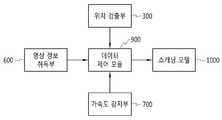
도 7은 본 발명의 일 실시 예에 의한 데이터 제어 모듈과 연계된 주요 구성을 도시한 블럭도.
도 8 내지 도 9는 본 발명의 일 실시 예에 따른 구강용 스캐너의 사용 상태도.
도 10은 본 발명의 일 실시 예에 따른 구강용 스캐너에 의한 다른 실시 예에 의한 사용 상태도.1 is a partially exploded perspective view of a scanner for oral cavity according to an embodiment of the present invention.
Figure 2 is a perspective view showing a phase shifter of the oral scanner according to another embodiment of the present invention.
3 is a view showing an example of a moving state of the phase shift unit of the oral scanner according to an embodiment of the present invention.
4 is a view showing the oral scanner in accordance with another embodiment of the present invention.
FIG. 5 is a diagram illustrating various embodiments of a first reflector installed in an oral scanner according to an embodiment of the present disclosure; FIG.
FIG. 6 is a diagram illustrating a trajectory of the light output unit irradiated to the second reflecting unit according to an embodiment of the present disclosure.
7 is a block diagram showing a main configuration associated with a data control module according to an embodiment of the present invention.
8 to 9 is a state diagram used in the oral scanner according to an embodiment of the present invention.
Figure 10 is a use state according to another embodiment by the oral scanner according to an embodiment of the present invention.
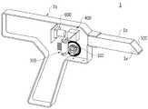
본 발명의 일 실시 예에 따른 구강용 스캐너의 구성에 대해 도면을 참조하여 설명한다. 첨부된 도 1은 본 발명의 일 실시 예에 따른 구강용 스캐너를 부분 분해 사시도이고, 도 2는 본 발명의 다른 실시 예에 따른 구강용 스캐너의 위상 변동부를 도시한 사시도이다.The configuration of an oral scanner according to an embodiment of the present invention will be described with reference to the drawings. 1 is a partially exploded perspective view of an oral scanner according to an embodiment of the present invention, and FIG. 2 is a perspective view illustrating a phase shift unit of the oral scanner according to another embodiment of the present invention.
첨부된 도 1을 참조하면, 본 발명의 일 실시 예에 의한 구강용 스캐너(1)는 피측정 대상물인 치아를 스캐닝하기 위해 환자가 입을 크게 벌리지 않고서도 정확한 측정을 가능하게 하고, 상기 구강용 스캐너(1)를 이용하여 치아를 스캐닝하는 동안 흔들림이 발생되는 경우에도 이를 정합시켜 3차원 스캐닝 모델을 안정적으로 생성할 수 있다.Referring to FIG. 1, the
이를 위해 본 발명의 일 실시 예에 의한 구강용 스캐너(1)는 시술자가 손으로 적어도 1개 이상의 손잡이(1d)가 형성된 스캐너 본체(1a)와, 상기 스캐너 본체(1a)에 결합되는 커버(1c) 및 상기 스캐너 본체(1a)의 전방에 설치되는 삽입체(1b)를 포함한다.To this end, the
본 실시 예에 의한 스캐너 본체(1a)는 시술자가 손으로 파지하기 위한 손잡이(1d)가 형성되고, 상기 손잡이(1d)의 상부 내측에 소정의 공간을 가지는 공간부가 형성되며, 삽입체(1b)의 선단부 일면이 개구된 개구부(1e)를 포함한다.
In the scanner main body 1a according to the present embodiment, a
삽입체(1b)는 상기 스캐너 본체(1a)와 선택적으로 착탈 가능하게 결합되고, 소정의 길이를 가지고 연장되며 바 형상의 직육면체 형태로 이루어지나 상기 형태로 반드시 한정하지 않는다. 삽입체(1b)는 환자의 구강 내부로 삽입되므로 인체에 무해한 재질로 제작되며 보다 상세한 설명은 후술하기로 한다.
The
본 발명의 일 실시 예에 의한 구강용 스캐너(1)는 내측에 레이저 광원이 조사되는 광 출력부(100)와, 상기 광 출력부(100)를 서로 다른 시간 동안 서로 다른 위상으로 변환시키는 위상 변동부(200)와, 상기 위상 변동부(200)의 이동에 따른 위치 또는 상태 정보를 검출하는 위상 검출부(300)와, 상기 광 출력부(100)와 서로 마주보며 배치되고 상기 광 출력부(100)에서 조사된 광을 굴절시키는 제1 반사부(400)와, 상기 제1 반사부(400)와 마주보며 배치되고, 상기 제1 반사부(400)를 통해 반사된 광을 환자의 구강에 배치된 피측정 대상물(10)을 향해 반사시키는 제2 반사부(500)와, 상기 제1 반사부(400)의 후방에 배치되어 상기 피측정 대상물(10)에서 반사된 반사광을 입력 받아 2차원 영상 정보로 변환하는 영상 정보 취득부(600); 및 상기 피측정 대상물(10)에 대한 데이터를 취득하는 동안 가속도 변화를 감지하는 가속도 감지부(700)를 포함한다.
In the
본 발명의 일 실시 예에 의한 광 출력부에 대해 설명한다.A light output unit according to an embodiment of the present invention will be described.
광 출력부(100)는 레이저 광이 발생되는 광 발생부와, 상기 광 발생부의 상면에 설치되고 라인 형태로 레이저 광을 제1 반사부(400)로 조사하기 위한 광학 위상 변화부를 포함한다.The
광 발생부는 통상의 레이저나, 발광 다이오드(LED) 또는 할로겐 램프 중의 어느 하나가 선택적으로 사용되고 본 실시 예에서는 설명의 편의를 위해 레이저로 한정하여 설명한다. 광학 위상 변화부는 제1 반사부(400)를 향해 선상의 광을 조사하여 선발광을 실시하며 작동에 필요한 전원은 내장된 배터리 또는 구강용 스캐너(1)의 외측으로 연장된 전원 케이블(미도시)을 통해 인가받아 작동된다. 광 출력부(100)는 후술할 제1 반사부(400)와 마주보며 배치되고, 위상 변동부(200)에 의해 이동 가능하게 설치된다.
The light generating unit may be any one of a conventional laser, a light emitting diode (LED), and a halogen lamp. The light generating unit may be selectively used. The optical phase shift unit emits light by irradiating linear light toward the
본 발명의 일 실시 예에 의한 위상 변동부에 대해 설명한다.A phase shift unit according to an embodiment of the present invention will be described.
위상 변동부(200)는 모터(210)에서 발생된 회전력을 전달받아 상기 광 출력부(100)가 안착된 안착부(201)를 왕복 이동시키는 이동부(220)를 포함한다.The
안착부(201)는 광 출력부(100)의 하측을 지지하고 상기 이동부(220)와 연결되며 도면에 도시된 바와 같이 플레이트 형태로 이루어지나 상기 형태로 반드시 한정하지 않는다.The
이동부(220)는 상기 모터(210)에 설치된 모터축에 삽입된 제1 링크(222)와, 상기 제1 링크(222)의 단부와 연결된 제2 링크(224)를 포함하고, 상기 제2 링크(224)는 제1 링크(222)에 비해 상대적으로 길이가 길게 연장되어 전술한 안착부(201)와 연결된다. 모터축이 회전되면 제1 링크(222)가 상기 모터축을 따라 회전되고, 상기 제1 링크(222)와 연결된 제2 링크(224)는 상기 제1 링크(222)에 의해 화살표 방향으로 왕복 이동된다.The moving
본 발명에 의한 구강용 스캐너(1)는 상기 안착부(201)의 안정적인 이동을 가이드 하는 가이드부(800)를 포함하고, 상기 가이드부(800)는 안착부(201)의 일부가 삽입된 상태가 유지되며 본 실시 예에서는 바 형태를 가지고 소정의 길이를 가지고 연장되고 사로 마주보며 상, 하로 이격된 상태로 설치된다.Scanner for
상기 안착부(201)는 상기 가이드부(800) 사이에 삽입된 상태로 설치되고, 상기 모터(210)의 회전에 의해 상기 가이드부(800)를 따라 상대 이동된다. 참고로 상기 가이드부(800)는 도면에 도시한 형태로 한정하지 않고 상기 광 출력부(100)가 안착된 안착부(201)가 이동되는 동안 안정적으로 이동 가능한 상태가 유지될 수 있는 다른 형태로 변경될 수 있음을 밝혀둔다.
The
본 발명의 다른 실시 예에 의한 위상 변동부에 대해 도면을 참조하여 설명한다.A phase shift unit according to another exemplary embodiment of the present invention will be described with reference to the drawings.
첨부된 도 2내지 도 3을 참조하면, 다른 실시 예에 위상 변동부(200)는 모터(210)에서 발생된 회전력을 전달받아 상기 광 출력부(100)를 정 위치에서 회전 이동시키기 위해 상기 광 출력부(100)의 외측에 권취된 벨트(230)와, 상기 광 출력부(100)의 외측을 향해 연장되고 상기 광 출력부(100)가 벨트에 의해 회전되는 동안 정 위치에서 회전되기 위해 구비된 회전축(240)을 포함한다.2 to 3, in another embodiment, the
광 출력부(100)는 상기 벨트(230)가 권취되도록 풀리 형태로 형성되고, 회전축(240)이 하측을 향해 소정의 길이를 가지고 연장된다. 상기 회전축(240)은 하단이 스캐너 본체(1a)의 내측에 형성된 홈(미도시)에 일부가 삽입된 상태가 유지되고, 상기 회전축(240) 또한 일정 부분 삽입되는 축 가이드(미도시)에 의해 벨트(230)가 회전되는 경우에도 일측으로 이동되지 않고 정 위치에서 회전될 수 있다.The
구강용 스캐너(1)는 정 위치에서 회전되는 광 출력부(100)의 위치 정보를 인식하기 위해 상기 광 출력부(100)의 하측에 원판 형태로 이루어지고 원주 방향으로 다수개의 슬릿홀이 형성된 회전판과, 상기 회전판의 슬릿홀을 기준으로 서로 마주보며 배치된 투광부와 수광부를 포함한다. 상기 회전판은 중앙에 상기 회전축(240)이 삽입되는 센터홀이 개구되어 있으므로 상기 회전판은 상기 회전축(240)과 함께 동시에 회전된다.Oral scanner (1) is a rotating plate formed in the form of a disc on the lower side of the
예를 들어 회전판이 회전되며 투광부에서 조사된 빛이 슬릿홀을 통해서 수광부를 통해 감지되고, 상기 슬릿홀이 미 형성된 부분에서는 상기 수광부를 통해 빛이 감지되지 않으므로 상기 광 출력부(100)가 설치된 회전판이 회전될 때마다 일정한 펄스가 발생되고 발생된 펄스는 데이터 제어 모듈(900)로 전송된다. 상기 데이터 제어 모듈(900)은 이를 입력받아 상기 광 출력부(100)의 회전에 따른 위치를 인식할 수 있다.
For example, since the rotating plate is rotated and the light emitted from the light transmitting unit is detected through the light receiving unit through the slit hole, and the light is not detected through the light receiving unit in the portion where the slit hole is not formed, the
본 발명의 일 실시 예에 의한 위상 검출부(300)는 엔코더(encoder)가 사용되고, 상기 엔코더는 상기 광 출력부(100)가 이동될 경우 위치 정보를 검출하여 후술할 데이터 제어 모듈(900)로 전송되며, 상기 데이터 제어 모듈(900)은 엔코더에서 전송한 신호를 입력받아 상기 광 출력부(100)의 서로 다른 위치를 연산한다.
The
본 발명의 또 다른 실시 예에 의한 구강용 스캐너에 대해 도면을 참조하여 설명한다.Oral scanner according to another embodiment of the present invention will be described with reference to the drawings.
첨부된 도 4를 참조하면, 전술한 구강용 스캐너의 요부 구성인 위상 검출부(300)와, 제1 반사부(400)와, 제2 반사부(500)와, 영상 정보 취득부(600)와, 삽입체(1b)와, 개구부(1e) 및 스캐너 본체(1a)의 구성은 동일하나, 광 출력부(100)가 시계 방향 또는 시계 반대 방향으로 회전 가능하게 설치된 구성으로 이루어진다.Referring to FIG. 4, the
이와 같이 광 출력부(100)가 설치될 경우 구성이 상대적으로 간단하고, 회전에 따른 진동 및 이로 인한 소음 발생이 최소화되어 영상 정보 취득부(600)를 통해 취득된 환자의 스캐닝 데이터에서 노이즈 발생이 최소화되므로 소프트웨어를 통해 정합하는 과정에서 연산 속도가 향상되고 연속성 또한 향상되어 보다 신속하고 정확한 환자의 치아에 대한 3차원 스캐닝 데이터를 획득할 수 있다.When the
참고로 위상 변동부(미도시)는 도시하지 않았으나, 광 출력부(100)의 측방 에 설치되거나, 후방에 설치되어 벨트 등으로 연결된다. 이때, 광출력부(100)의 전원공급은 브러시(미도시)전원공급방식이 사용될 수 있으나 반드시 이로 한정하지 않는다.
For reference, the phase shifter (not shown) is not shown, but is installed at the side of the
본 발명의 일 실시 예에 의한 제1 반사부에 대해 도면을 참조하여 설명한다.A first reflecting unit according to an embodiment of the present invention will be described with reference to the drawings.
첨부된 도 5의 (a) 내지 (c)를 참조하면, 제1 반사부(400)는 증착 코팅된 평면유리 또는 증착 코팅된 직각프리즘 또는 증착 코팅된 접합프리즘 중의 어느 하나가 선택적으로 사용될 수 있다.Referring to FIGS. 5A through 5C, the
예를 들어 증착 코팅된 평면유리는 도5의 (a) 상태로서, 화살표 방향으로 도시된 바와 같이 광출력부(100)에서 조사된 레이저 광이 제1 반사부(400)를 향해 조사된 뒤에 도면 기준으로 우측을 향해 굴절되어 이동되고, 치아에 조사된 후에 반사된 레이저는 제1 반사부(400)로 재 반사되어 영상 정보 취득부(600)로 입력된다.For example, the deposition-coated flat glass is a state in FIG. 5A, after the laser light emitted from the
증착 코팅된 직각프리즘은 도5의 (b) 상태로서, 화살표 방향으로 도시된 바와 같이 광출력부(100)에서 조사된 레이저 광이 제1 반사부(400)를 향해 조사된 뒤에 도면 기준으로 우측을 향해 직각으로 굴절되어 이동되고, 치아에 조사된 후에 반사된 레이저는 제1 반사부(400)로 재 반사되어 영상 정보 취득부(600)로 입력된다.The deposition-coated right angle prism is shown in FIG. The laser is refracted and moved at right angles toward, and the reflected laser after being irradiated to the teeth is reflected back to the
증착 코팅된 접합프리즘은 도5의 (c) 상태로서, 직각 프리즘 2개를 서로 마주보는 상태로 접합시켜 사용하며 굴절이 최소화된 상태로 사용할 수 있으므로 영상 정보 취득부(600)로 입력되는 데이터의 정밀도가 보다 향상된다.
The deposition-coated bonded prism is a state of FIG. 5 (c), and the two rectangular prisms are bonded to each other in a state of facing each other, and can be used in a state where the refractive is minimized. Precision is further improved.
첨부된 도 6을 참조하면, 본 발명의 일 실시 예에 의한 프리즘(400)은 광 출력부(100)의 상측에 접합프리즘이 사용되고, 내측에 소정의 각도로 경사진 반사판이 설치되어 상기 광 출력부(100)에서 조사된 광을 부분 반사한다.Referring to FIG. 6, in the
상기 제1 반사부(400)는 가로 길이와 세로 길이가 동일 길이로 형성되는데 상기 광 출력부(100)에서 조사된 광은 선발광 형태로 조사가 이루어지는데 광 출력부(100)가 위상 변동부(200)에 의해 화살표 방향으로 이동될 경우 제1 반사부(400)에서는 굵은 실선으로 도시된 형태로 광이 조사되고, 각각의 조사된 광은 제2 반사부(500)를 향해 직진 이동된다.The
또한 광 출력부(100)는 위상 변동부(200)에 의해 왕복 이동 운동이 이루어지되, 상기 광 출력부가 이동되는 전체 스트로크(S)는 상기 제1 반사부(400)의 세로 길이와 대응되는 길이로 이동되며, 상기 제1 반사부(400)의 가로 길이와 세로 길이의 면적은 일반적인 치아 크기의 1.5배의 면적에 해당되므로 상기 제1 반사부(400)를 통해 조사된 광은 치아를 스캐닝할 때 충분히 커버할 수 있으므로 정확한 스캐닝 데이터를 획득할 수 있다.
In addition, the
본 발명의 일 실시 예에 의한 제2 반사부에 대해 설명한다.A second reflector according to an embodiment of the present invention will be described.
제2 반사부(500)는 제1 반사부(400)를 통해 조사된 광을 완전 반사시켜 피측정 대상물(10)인 차아로 굴절시키며, 삽입체(1b)의 선단부 내측에 삽입된다. 제2 반사부(500)는 상기 제1 반사부(400)와 대응되는 크기를 가지고 설치되고 45°각도로 경사지게 설치되어 개구부(1e)로 광을 반사시킨다.
The second reflecting
본 발명의 일 실시 예에 의한 영상 정보 취득부에 대해 설명한다.An image information acquisition unit according to an embodiment of the present invention will be described.
영상 정보 취득부(600)는 제1 반사부(400)의 후방에 설치되고, 광 출력부(100)를 통해 조사된 광이 제1,2 제2 반사부(400,500)를 통해 치아로 조사되고, 상기 치아에 조사된 광이 재반사되어 상기 제2 반사부(500)를 경유하여 제1 반사부(400)로 이동된 후에 상기 제1 반사부(400)를 경유하여 상기 영상 정보 취득부(600)를 통해 입력된다. 상기 영상 정보 취득부(600)는 전하결합소자(Charge Coupled Device)가 사용되나 이와 유사한 기능이 구현되는 CMOS소자가 사용되는 것도 가능함을 밝혀둔다.
The image
본 발명의 일 실시 예에 의한 가속도 감지부에 대해 설명한다.An acceleration sensing unit according to an embodiment of the present invention will be described.
첨부된 도 1 또는 도 2를 참조하면, 가속도 감지부(700)는 시술자가 구강용 스캐너(1)를 이용하여 환자의 구강 내부의 치아를 스캐닝하는 동안 X축 또는 Y축 및 Z축 방향을 향해 이동하면서 측정을 실시하며, 이 경우 이동 과정에서 흔들림이 발생되거나 상기 구강용 스캐너(1)가 환자의 구강안에서 부분적인 접촉 또는 치아와 충돌되어 흔들림이 발생될 수 있다. 본 발명은 이와 같은 흔들림 및 충격에 의한 스캐닝 데이터의 오류를 최소화하기 위해 상기 가속도 감지부(700)를 통해 상기 구강용 스캐너(1)의 가속도 정보를 센싱하여 데이터 제어 모듈(900)로 전송하며 일 예로 상기 가속도 감지부(700)는 가속도 센서가 사용될 수 있다.
Referring to FIG. 1 or FIG. 2, the acceleration detection unit 700 is directed toward the X-axis or the Y-axis and the Z-axis while the operator scans the teeth inside the patient's mouth using the
본 발명의 일 실시 예에 의한 데이터 제어 모듈에 대해 도면을 참조하여 설명한다.A data control module according to an embodiment of the present invention will be described with reference to the drawings.
첨부된 도 2를 참조하면, 데이터 제어 모듈(900)은 전술한 영상 정보 취득부(600)를 통해 취득된 치아의 2차원 정보와, 상기 가속도 감지부(700)를 통해 입력된 가속도 정보를 모두 입력받아 상기 환자의 치아에 대한 3차원 스캐닝 모델(첨부된 도 9의 N1과 N2)을 생성한다.Referring to FIG. 2, the
또한 환자의 치아에 대한 정보를 정합하기 위해 위상 검출부(300)와, 가속도 감지부(700) 및 영상 정보 취득부(600)를 통해 각각 데이터를 입력받아 스캐닝 모델(1000) (첨부된 도 9의 d)을 완성한다.
In addition, in order to match the information on the patient's teeth, the data is received through the
이와 같이 구성된 본 발명의 일 실시 예에 의한 구강용 스캐너의 사용 상태에 대해 도면을 참조하여 설명한다.A state of use of the oral scanner according to an embodiment of the present invention configured as described above will be described with reference to the drawings.
첨부된 도 7 내지 도 8을 참조하면, 시술자는 환자의 구강 내부에 배치된 치아에 대한 3차원 스캐닝 작업을 실시하기 전에 삽입체(1b)를 스캐너 본체(1a)의 선단부에 맞추어서 도면과 같이 조립한다.7 to 8, the operator assembles the
그리고 환자의 구강 내부로 상기 삽입체(1b)를 이동시킨 후에 전원 스위치를(미도시)를 온 상태로 전환하면 광 출력부(100)에서 조사된 광이 제1 반사부(400)를 향해 조사된다. 광 출력부(100)는 선발광이 이루어지도록 렌즈의 전면에 별도의 선발광용 광학체가 설치되어 있으므로 도면에 도시된 바와 같이 제1 반사부(400)와 동일 내지 유사한 길이를 가지고 선발광이 이루어진다. 이와 동시에 모터(210)에 설치된 모터축이 회전되면서 제1 링크(222)는 상기 모터축과 함께 회전되고, 제2 링크(224)가 회전되면서 안착부(201)에 설치된 광 출력부(100)는 화살표 방향으로 왕복 이동되면서 광이 조사된다.Then, after moving the
본 실시 예에 의한 광 출력부(100)는 가이드부(800)에 의해 위와 같은 상태로 이동이 이루어지는 동안 외측으로 이탈되거나 오작동 되지 않고 안정적으로 왕복 이동이 이루어진다.The
첨부된 도 2 및 도 8을 참조하면, 제1 반사부(400)를 향해 조사된 광은 일부가 투과되고 나머지 일부가 제2 반사부(500)를 향해 직진 이동되고, 상기 제2 반사부(500)를 통해 치아를 향해 조사되고, 상기 치아에 조사된 광은 다시 반사되어 상기 제2 반사부(500)로 조사되어 제1 반사부(400)를 경유하여 영상 정보 취득부(600)를 통해 2차원 영상 데이터로 입력된다. 시술자는 환자의 구강에 배치된 치아에 대해 위와 같은 방법으로 삽입체(1b)의 위치를 이동시켜가면서 환자의 치아에 대한 스캐닝 작업을 실시한다.2 and 8, a portion of the light irradiated toward the first reflecting
위상 검출부(300)는 위상 검출부(300)은 상기 광출력부(100)가 서로 다른 위상으로 변동될 경우 각각의 위상에서 조사된 출력광의 서로 다른 위상 데이터를 제어모듈(900)로 전송하여 3차원 스캐닝 모델의 구성에 이용된다.
The
본 실시 예에 의한 구강용 스캐너(1)는 제 1 반사부(400) 면적 이상의 구강영역에 대한 3차원 정보를 획득해야 하고, 이를 위해 스캐닝 대상영역을 이동해야 한다. 이때 제 1 반사부(400) 면적에 해당하는 3차원 정보(도9, N1)를 우선적으로 구성하고, 스캐너의 위치를 이동한 뒤, 새로운 3차원 정보(도9, N2)를 구성하여 이를 상호 정합(도9, d)한다. 이때, 가속도 감지부(700)를 통해 수취된 스캐너의 이동방향과 이동량에 대한 정보를 이용하여 서로 다른 스캐너 위치에서 구성된 각각의3차원 정보를 정합하는 데에 활용할 수 있어, 본 발명의 스캐너로 구강의 전 영역에 대한 3차원 정보를 획득하는 것이 가능해진다.
The
이와 같이 시술자에 의해 취득된 환자의 치아에 대한 2차원 정보와, 위상 검출부(300)에서 검출된 광 출력부(100)의 위치 정보 및 가속도 감지부(700)를 통해 감지된 구강용 스캐너(1)의 데이터는 영상 정보 취득부(600)를 통해 각각 입력되고, 상기 영상 정보 취득부(600)는 이를 모두 정합시켜 환자의 치아에 대한 3차원 스캐닝 모델을 연산한다.
The two-dimensional information on the teeth of the patient obtained by the operator in this way, the position information of the
첨부된 도 9을 참조하면, 예를 들어 시술자가 치아에 대한 스캐닝 작업을 실시하다가 제1 번 치아(N1)(a 상태)에 대한 스캐닝 작업 이후에 제2번 치아(N2)(b 상태)에 대한 스캐닝 작업을 실시하는 도중 구강용 스캐너(1)에 흔들림이 발생될 경우 상기 제1,2 번 치아(N1,N2)는 전체 형태가 기록되지 않고 부분적으로 절단된 형태로 데이터 처리된다.Referring to FIG. 9, for example, the operator performs a scanning operation on a tooth and then, after the scanning operation on the first tooth N1 (a state), moves to a second tooth N2 (b state). When shaking occurs in the
본 발명의 데이터 제어 모듈(900)은 이와 같이 부분 절단된 제1,2 번 치아(N1,N2)의 영상 정보와 가속도 정보를 이용하여 정합을 실시하면 도면에 도시된 바와 같이 정합치아(c 상태)의 스캐닝 모델이 생성되므로 치아에 대한 스캐닝을 실시하는 동안 발생될 수 있는 흔들림과 위치 이동에 상관없이 정밀도가 우수한 치아의 스캐닝 모델이 생성된다.
When the
시술자는 환자의 상악에 배치된 다수개의 치아 또는 구강내의 전영역에 대한 스캐닝을 실시하기 위해 다음과 같이 실시한다.The operator performs as follows to scan the entire area of the mouth or the plurality of teeth placed in the maxilla of the patient.
첨부된 도 10을 참조하면, 시술자는 구강용 스캐너(1)를 환자의 구강 외측으로 인출시킨 후에 삽입체(1b)를 스캐너 본체(1a)의 외측으로 인출시켜 개구부(1e)가 상측을 향하도록 삽입체(1b)를 회전시킨 후에 상기 스캐너 본체(1a)의 선단부에 결합시켜 사용한다.Referring to FIG. 10, the operator draws the
본 발명에 의한 삽입체(1b)는 전술한 바와 같이 스캐너 본체(1a)의 선단부에서 선택적으로 탈착 가능하게 설치되거나, 상대 회전 가능하게 설치될 수 있으며 이 경우 스캐너 본체(1a)의 선단부에 삽입체(1b)가 삽입된 부분만 회전되면서 시술자가 개구부(1e)를 확인하고 상악 또는 하악에 배치된 치아에 대한 스캐닝 작업을 보다 효율적으로 실시할 수 있다.
The
이상, 본 발명의 일 실시 예에 대하여 설명하였으나, 해당 기술 분야에서 통상의 지식을 가진 자라면 특허청구범위에 기재된 본 발명의 사상으로부터 벗어나지 않는 범위 내에서, 구성 요소의 부가, 변경, 삭제 또는 추가 등에 의해 본 발명을 다양하게 수정 및 변경시킬 수 있을 것이며, 이 또한 본 발명의 권리범위 내에 포함된다고 할 것이다.
It will be apparent to those skilled in the art that various modifications and variations can be made in the present invention without departing from the spirit of the invention as set forth in the appended claims. The present invention can be variously modified and changed by those skilled in the art, and it is also within the scope of the present invention.
1a : 스캐너 본체
1b : 삽입체
1d : 손잡이
1e : 개구부
10 : 피측정 대상물
100 : 광 출력부
200 : 위상 변동부
201 : 안착부
220 : 이동부
222, 224 : 제1,2 링크
300 : 위상 검출부
400 : 제2 반사부
500 : 제2 반사부
600 : 영상 정보 취득부
700 : 가속도 감지부
800 : 가이드부1a: Scanner Body
1b: insert
1d: handle
1e: opening
10: object to be measured
100: light output unit
200: phase shift unit
201: seating part
220:
222, 224
300: phase detection unit
400: second reflecting unit
500: second reflecting unit
600: image information acquisition unit
700: acceleration detection unit
800: guide portion
Claims (15)
Translated fromKorean상기 광 출력부로부터 출력된 출력광을 서로 다른 시간 동안 서로 다른 위상으로 변환시키는 위상 변동부;
상기 위상 변동부의 이동에 따른 위치 또는 상태 정보를 검출하는 위상 검출부;
상기 광 출력부와 서로 마주보며 배치되고 상기 광 출력부에서 조사된 광을 굴절시키는 제1 반사부;
상기 제1 반사부와 마주보며 배치되고, 상기 제1 반사부를 통해 반사된 광을 환자의 구강에 배치된 피측정 대상물을 향해 반사시키는 제2 반사부;
상기 제1 반사부의 후방에 배치되어 상기 피측정 대상물에서 반사된 반사광을 입력받아 2차원 영상 정보로 변환하는 영상 정보 취득부; 및
상기 피측정 대상물에 대한 데이터를 취득하는 동안 가속도 변화를 감지하는 가속도 감지부를 포함하는 구강용 스캐너.A light output unit to which the laser light source is irradiated;
A phase shifter for converting output light output from the light output part into different phases for different times;
A phase detector for detecting position or state information according to the movement of the phase shifter;
A first reflector disposed to face the light output unit and refracting light emitted from the light output unit;
A second reflector disposed to face the first reflector and reflecting light reflected through the first reflector toward an object to be measured disposed in a mouth of a patient;
An image information acquisition unit disposed behind the first reflector and configured to receive reflected light reflected from the object to be measured and convert the received light into two-dimensional image information; And
An oral scanner comprising an acceleration detection unit for detecting an acceleration change while acquiring data on the object to be measured.
상기 광 출력부는,
레이저 광이 발생되는 광 발생부;
상기 광 발생부의 상면에 설치되고 라인 형태로 레이저 광을 제1 반사부로 조사하기 위한 광학 위상 변화부를 포함하는 구강용 스캐너.The method according to claim 1,
The light output unit,
A light generator for generating laser light;
An oral scanner provided on an upper surface of the light generating unit and including an optical phase change unit for irradiating the laser light to the first reflecting unit in the form of a line.
상기 제1 반사부는,
증착 코팅된 평면유리 또는 증착 코팅된 직각프리즘 또는 증착 코팅된 접합프리즘 중의 어느 하나가 선택적으로 사용되는 구강용 스캐너.The method according to claim 1,
Wherein the first reflecting portion comprises:
An oral scanner in which either vapor-coated flat glass or vapor-coated right angle prism or vapor-coated bonded prism is selectively used.
상기 제1 반사부는,
반투과 타입의 프리즘 또는 유리 중의 어느 하나가 선택적으로 사용되는 구강용 스캐너.The method according to claim 1,
Wherein the first reflecting portion comprises:
An oral scanner in which either a transflective prism or glass is optionally used.
상기 제1 반사부는,
가로 길이와 세로 길이와 각각 동일 길이로 이루어진 것을 특징으로 하는 구강용 스캐너.The method according to claim 1,
Wherein the first reflecting portion comprises:
An oral scanner, characterized in that consisting of the same length and width and length respectively.
상기 위상 변동부는,
전기와 자석 사이에서 발생된 전자기력을 통해 회전 또는 직선 이동력을 전달받아 상기 광 출력부가 안착된 안착부를 왕복 이동시키는 이동부를 포함하는 구강용 스캐너.The method according to claim 1,
The phase shift unit,
The oral cavity scanner including a moving unit for receiving a rotational or linear movement force through the electromagnetic force generated between the electricity and the magnet to reciprocate the seating portion on which the light output unit is seated.
상기 위상 변동부는,
전기와 자석 사이에서 발생된 전자기력을 통해 회전력을 전달받아 상기 광 출력부가 안착된 안착부를 회전 이동시키는 이동부를 포함하는 구강용 스캐너.The method according to claim 1,
The phase shift unit,
An oral scanner comprising a moving unit for receiving a rotational force through the electromagnetic force generated between the electricity and the magnet to rotate the seating portion seated on the light output.
상기 위상 변동부는,
모터에서 발생된 회전력을 전달받아 상기 광 출력부를 정 위치에서 회전 이동시키는 회전축을 포함하는 구강용 스캐너.The method according to claim 1,
The phase shift unit,
Receiving a rotational force generated from the motor scanner for oral cavity comprising a rotating shaft for rotating the light output in a fixed position.
상기 구강용 스캐너는,
상기 안착부의 안정적인 이동을 가이드 하는 가이드부를 포함하는 구강용 스캐너.The method of claim 6,
The oral scanner,
Oral scanner comprising a guide for guiding the stable movement of the seating portion.
상기 위상 변동부는,
모터에서 발생된 회전력을 전달받아 상기 광 출력부를 정 위치에서 회전 이동시키기 위해 상기 광 출력부의 외측에 권취된 벨트;
상기 광 출력부의 외측을 향해 연장되고 상기 광 출력부가 벨트에 의해 회전되는 동안 정 위치에서 회전되기 위해 구비된 회전축을 포함하는 구강용 스캐너.The method according to claim 1,
The phase shift unit,
A belt wound on the outside of the light output part to receive the rotational force generated from the motor and to rotate the light output part in a fixed position;
And an axis of rotation extending toward the outside of the light output portion and provided to rotate in position while the light output portion is rotated by a belt.
상기 제2 반사부는,
상기 제1 반사부를 통해 조사된 광을 완전 반사시켜 상기 피측정 대상물로 굴절시키는 구강용 스캐너.The method according to claim 1,
Wherein the second reflecting portion comprises:
The oral scanner for completely refracting the light irradiated through the first reflecting portion to the object to be measured.
상기 구강용 스캐너는,
상기 영상 정보 취득부와 위상 검출부로부터 전송된 데이터를 연산하여 복수개의 3차원 데이터를 생성하고, 상기 3차원 데이터를 가속도 감지부를 통해 전송된 데이터를 이용하여 정합함으로써 환자의 피측정 대상물에 대한 스캐닝 모델을 생성하는 것을 특징으로 하는 구강용 스캐너.The method according to claim 1,
The oral scanner,
Scanning model for the subject to be measured by calculating a plurality of three-dimensional data by calculating the data transmitted from the image information acquisition unit and the phase detector, and matching the three-dimensional data using the data transmitted through the acceleration detection unit Oral scanner, characterized in that for generating.
상기 구강용 스캐너는,
시술자가 손으로 파지되는 스캐너 본체;
상기 스캐너 본체의 전방에 설치되고 선단부에 상기 제2 반사부가 설치되어 환자의 구강 내측으로 삽입되는 삽입체를 포함하는 구강용 스캐너.The method according to claim 1,
The oral scanner,
A scanner body that the operator grips by hand;
And an insert installed at the front of the scanner body and having a second reflecting portion installed at a distal end thereof and inserted into the mouth of the patient.
상기 삽입체는,
상기 스캐너 본체와 선택적으로 착탈 가능하게 결합되는 것을 특징으로 하는 구강용 스캐너.The method of claim 13,
Said insert comprising:
An oral scanner, which is selectively detachably coupled to the scanner body.
상기 삽입체는,
상기 스캐너 본체에 결합된 상태로 길이 방향을 축으로 상대 회전되는 것을 특징으로 하는 구강용 스캐너.The method of claim 13,
Said insert comprising:
The oral cavity scanner, characterized in that the relative rotation in the longitudinal direction in the state coupled to the scanner body.
Priority Applications (1)
| Application Number | Priority Date | Filing Date | Title |
|---|---|---|---|
| KR1020130081775AKR101371211B1 (en) | 2013-07-11 | 2013-07-11 | Scanner for oral cavity |
Applications Claiming Priority (1)
| Application Number | Priority Date | Filing Date | Title |
|---|---|---|---|
| KR1020130081775AKR101371211B1 (en) | 2013-07-11 | 2013-07-11 | Scanner for oral cavity |
Publications (1)
| Publication Number | Publication Date |
|---|---|
| KR101371211B1true KR101371211B1 (en) | 2014-03-10 |
Family
ID=50647781
Family Applications (1)
| Application Number | Title | Priority Date | Filing Date |
|---|---|---|---|
| KR1020130081775AExpired - Fee RelatedKR101371211B1 (en) | 2013-07-11 | 2013-07-11 | Scanner for oral cavity |
Country Status (1)
| Country | Link |
|---|---|
| KR (1) | KR101371211B1 (en) |
Cited By (13)
| Publication number | Priority date | Publication date | Assignee | Title |
|---|---|---|---|---|
| WO2015174741A1 (en)* | 2014-05-14 | 2015-11-19 | 주식회사 바텍 | 3d scanner for dental clinic |
| KR20150130938A (en)* | 2014-05-14 | 2015-11-24 | 주식회사바텍 | Dental three-dimensional scanner |
| KR20160020268A (en) | 2014-08-13 | 2016-02-23 | 석재승 | Oral 3-D scanner |
| WO2016164238A1 (en)* | 2015-04-10 | 2016-10-13 | 3M Innovative Properties Company | A dental light irradiation device |
| KR101844746B1 (en)* | 2016-06-17 | 2018-04-05 | 오스템임플란트 주식회사 | Scanner for oral cavity and method for protecting steam thereof |
| WO2020032572A1 (en)* | 2018-08-07 | 2020-02-13 | 주식회사 메디트 | Three-dimensional intraoral scanner |
| WO2020032556A1 (en)* | 2018-08-07 | 2020-02-13 | 주식회사 메디트 | Handle for three-dimensional oral scanner |
| KR20200016803A (en)* | 2018-08-07 | 2020-02-17 | 주식회사 메디트 | Handle for 3-dimensional intraoral scanner |
| CN112074228A (en)* | 2018-05-03 | 2020-12-11 | 株式会社美迪特 | Three-dimensional oral cavity scanner |
| WO2023075545A1 (en)* | 2021-10-29 | 2023-05-04 | 아크리얼 주식회사 | Intraoral scanner |
| KR20230060336A (en)* | 2021-10-27 | 2023-05-04 | 주식회사 메디트 | Three dimensional oral scanner |
| US12090026B2 (en) | 2018-08-07 | 2024-09-17 | Medit Corp. | Three-dimensional intraoral scanner |
| WO2025193005A1 (en)* | 2024-03-15 | 2025-09-18 | 주식회사 메디트 | Handheld-type scanner having self-diagnosis function using impact sensor and self-diagnosis method using same |
Citations (4)
| Publication number | Priority date | Publication date | Assignee | Title |
|---|---|---|---|---|
| JP2009078133A (en)* | 2007-08-16 | 2009-04-16 | Steinbichler Optotechnik Gmbh | Device for determining 3d coordinates of object, in particular of tooth |
| KR20110068954A (en)* | 2011-01-26 | 2011-06-22 | 데오덴탈 주식회사 | Oral Scanner |
| JP2012223577A (en)* | 2011-04-18 | 2012-11-15 | Leica Microsystems (Schweiz) Ag | Operating microscope system |
| KR20130019296A (en)* | 2011-08-16 | 2013-02-26 | 주식회사 오라픽스 | Scanning system and method for oral cavity |
- 2013
- 2013-07-11KRKR1020130081775Apatent/KR101371211B1/ennot_activeExpired - Fee Related
Patent Citations (4)
| Publication number | Priority date | Publication date | Assignee | Title |
|---|---|---|---|---|
| JP2009078133A (en)* | 2007-08-16 | 2009-04-16 | Steinbichler Optotechnik Gmbh | Device for determining 3d coordinates of object, in particular of tooth |
| KR20110068954A (en)* | 2011-01-26 | 2011-06-22 | 데오덴탈 주식회사 | Oral Scanner |
| JP2012223577A (en)* | 2011-04-18 | 2012-11-15 | Leica Microsystems (Schweiz) Ag | Operating microscope system |
| KR20130019296A (en)* | 2011-08-16 | 2013-02-26 | 주식회사 오라픽스 | Scanning system and method for oral cavity |
Cited By (19)
| Publication number | Priority date | Publication date | Assignee | Title |
|---|---|---|---|---|
| KR20150130938A (en)* | 2014-05-14 | 2015-11-24 | 주식회사바텍 | Dental three-dimensional scanner |
| KR101699250B1 (en)* | 2014-05-14 | 2017-01-24 | 주식회사바텍 | Dental three-dimensional scanner |
| WO2015174741A1 (en)* | 2014-05-14 | 2015-11-19 | 주식회사 바텍 | 3d scanner for dental clinic |
| KR20160020268A (en) | 2014-08-13 | 2016-02-23 | 석재승 | Oral 3-D scanner |
| WO2016164238A1 (en)* | 2015-04-10 | 2016-10-13 | 3M Innovative Properties Company | A dental light irradiation device |
| US10758126B2 (en) | 2015-04-10 | 2020-09-01 | 3M Innovative Properties Company | Dental irradiation device |
| KR101844746B1 (en)* | 2016-06-17 | 2018-04-05 | 오스템임플란트 주식회사 | Scanner for oral cavity and method for protecting steam thereof |
| CN112074228A (en)* | 2018-05-03 | 2020-12-11 | 株式会社美迪特 | Three-dimensional oral cavity scanner |
| CN112074228B (en)* | 2018-05-03 | 2024-05-31 | 株式会社美迪特 | 3D Oral Scanner |
| US11903678B2 (en) | 2018-05-03 | 2024-02-20 | Medit Corp. | 3-dimensional intraoral scanner |
| KR20200016803A (en)* | 2018-08-07 | 2020-02-17 | 주식회사 메디트 | Handle for 3-dimensional intraoral scanner |
| KR102266641B1 (en) | 2018-08-07 | 2021-06-21 | 주식회사 메디트 | Handle for 3-dimensional intraoral scanner |
| WO2020032556A1 (en)* | 2018-08-07 | 2020-02-13 | 주식회사 메디트 | Handle for three-dimensional oral scanner |
| WO2020032572A1 (en)* | 2018-08-07 | 2020-02-13 | 주식회사 메디트 | Three-dimensional intraoral scanner |
| US12090026B2 (en) | 2018-08-07 | 2024-09-17 | Medit Corp. | Three-dimensional intraoral scanner |
| KR20230060336A (en)* | 2021-10-27 | 2023-05-04 | 주식회사 메디트 | Three dimensional oral scanner |
| KR102631396B1 (en)* | 2021-10-27 | 2024-02-01 | 주식회사 메디트 | Three dimensional oral scanner |
| WO2023075545A1 (en)* | 2021-10-29 | 2023-05-04 | 아크리얼 주식회사 | Intraoral scanner |
| WO2025193005A1 (en)* | 2024-03-15 | 2025-09-18 | 주식회사 메디트 | Handheld-type scanner having self-diagnosis function using impact sensor and self-diagnosis method using same |
Similar Documents
| Publication | Publication Date | Title |
|---|---|---|
| KR101371211B1 (en) | Scanner for oral cavity | |
| JP7383595B2 (en) | Device for intraoral imaging and device for confocal imaging | |
| KR101043976B1 (en) | Oral Scanner | |
| KR101533341B1 (en) | Portable Scanner | |
| CN106794052B (en) | Device and method for optically measuring surface topography | |
| KR102401548B1 (en) | Device and method for subgingival measurement | |
| CA2893035C (en) | Dental scanner device and related method | |
| US9522054B2 (en) | Scanner for oral cavity | |
| JP5642114B2 (en) | Dental optical measurement device and dental optical measurement diagnostic instrument | |
| KR101832753B1 (en) | Apparatus for scanning for both model and oral cavity | |
| CN107072530A (en) | Use the dental surface imaging equipment of laser projection | |
| KR102458985B1 (en) | Tomography convergence type oral scanner | |
| CN107427231B (en) | Method and measuring system for optically measuring an object | |
| KR101699250B1 (en) | Dental three-dimensional scanner | |
| KR101137516B1 (en) | Scaner for oral cavity and system for manufacturing teeth mold | |
| US11357601B2 (en) | Electronic impression tray for obtaining dental information | |
| WO2017029670A1 (en) | Intra-oral mapping of edentulous or partially edentulous mouth cavities | |
| KR20110068954A (en) | Oral Scanner | |
| KR101538760B1 (en) | Scanner for Oral Cavity | |
| KR102137544B1 (en) | Apparatus and method for generating dental three-dimiension surface image | |
| KR101524605B1 (en) | Three-dimensional apparatus for measuring tooth in mouth | |
| JP6198688B2 (en) | Probe, optical coherence tomographic image generation apparatus, and zero point correction method | |
| JP2022012590A (en) | Oral measuring device |
Legal Events
| Date | Code | Title | Description |
|---|---|---|---|
| A201 | Request for examination | ||
| PA0109 | Patent application | St.27 status event code:A-0-1-A10-A12-nap-PA0109 | |
| PA0201 | Request for examination | St.27 status event code:A-1-2-D10-D11-exm-PA0201 | |
| A302 | Request for accelerated examination | ||
| PA0302 | Request for accelerated examination | St.27 status event code:A-1-2-D10-D17-exm-PA0302 St.27 status event code:A-1-2-D10-D16-exm-PA0302 | |
| D13-X000 | Search requested | St.27 status event code:A-1-2-D10-D13-srh-X000 | |
| D14-X000 | Search report completed | St.27 status event code:A-1-2-D10-D14-srh-X000 | |
| E902 | Notification of reason for refusal | ||
| PE0902 | Notice of grounds for rejection | St.27 status event code:A-1-2-D10-D21-exm-PE0902 | |
| P11-X000 | Amendment of application requested | St.27 status event code:A-2-2-P10-P11-nap-X000 | |
| P13-X000 | Application amended | St.27 status event code:A-2-2-P10-P13-nap-X000 | |
| E701 | Decision to grant or registration of patent right | ||
| PE0701 | Decision of registration | St.27 status event code:A-1-2-D10-D22-exm-PE0701 | |
| GRNT | Written decision to grant | ||
| PR0701 | Registration of establishment | St.27 status event code:A-2-4-F10-F11-exm-PR0701 | |
| PR1002 | Payment of registration fee | St.27 status event code:A-2-2-U10-U11-oth-PR1002 Fee payment year number:1 | |
| PG1601 | Publication of registration | St.27 status event code:A-4-4-Q10-Q13-nap-PG1601 | |
| PN2301 | Change of applicant | St.27 status event code:A-5-5-R10-R13-asn-PN2301 St.27 status event code:A-5-5-R10-R11-asn-PN2301 | |
| R18-X000 | Changes to party contact information recorded | St.27 status event code:A-5-5-R10-R18-oth-X000 | |
| R18-X000 | Changes to party contact information recorded | St.27 status event code:A-5-5-R10-R18-oth-X000 | |
| P22-X000 | Classification modified | St.27 status event code:A-4-4-P10-P22-nap-X000 | |
| R18-X000 | Changes to party contact information recorded | St.27 status event code:A-5-5-R10-R18-oth-X000 | |
| R18-X000 | Changes to party contact information recorded | St.27 status event code:A-5-5-R10-R18-oth-X000 | |
| FPAY | Annual fee payment | Payment date:20170811 Year of fee payment:4 | |
| PR1001 | Payment of annual fee | St.27 status event code:A-4-4-U10-U11-oth-PR1001 Fee payment year number:4 | |
| PN2301 | Change of applicant | St.27 status event code:A-5-5-R10-R13-asn-PN2301 St.27 status event code:A-5-5-R10-R11-asn-PN2301 | |
| R18-X000 | Changes to party contact information recorded | St.27 status event code:A-5-5-R10-R18-oth-X000 | |
| LAPS | Lapse due to unpaid annual fee | ||
| PC1903 | Unpaid annual fee | St.27 status event code:A-4-4-U10-U13-oth-PC1903 Not in force date:20180301 Payment event data comment text:Termination Category : DEFAULT_OF_REGISTRATION_FEE | |
| P22-X000 | Classification modified | St.27 status event code:A-4-4-P10-P22-nap-X000 | |
| R18-X000 | Changes to party contact information recorded | St.27 status event code:A-5-5-R10-R18-oth-X000 | |
| R18-X000 | Changes to party contact information recorded | St.27 status event code:A-5-5-R10-R18-oth-X000 | |
| R18-X000 | Changes to party contact information recorded | St.27 status event code:A-5-5-R10-R18-oth-X000 | |
| PC1903 | Unpaid annual fee | St.27 status event code:N-4-6-H10-H13-oth-PC1903 Ip right cessation event data comment text:Termination Category : DEFAULT_OF_REGISTRATION_FEE Not in force date:20180301 | |
| R18-X000 | Changes to party contact information recorded | St.27 status event code:A-5-5-R10-R18-oth-X000 | |
| PN2301 | Change of applicant | St.27 status event code:A-5-5-R10-R13-asn-PN2301 St.27 status event code:A-5-5-R10-R11-asn-PN2301 | |
| R18-X000 | Changes to party contact information recorded | St.27 status event code:A-5-5-R10-R18-oth-X000 | |
| R18-X000 | Changes to party contact information recorded | St.27 status event code:A-5-5-R10-R18-oth-X000 | |
| R18-X000 | Changes to party contact information recorded | St.27 status event code:A-5-5-R10-R18-oth-X000 | |
| R18-X000 | Changes to party contact information recorded | St.27 status event code:A-5-5-R10-R18-oth-X000 | |
| R18-X000 | Changes to party contact information recorded | St.27 status event code:A-5-5-R10-R18-oth-X000 | |
| R18-X000 | Changes to party contact information recorded | St.27 status event code:A-5-5-R10-R18-oth-X000 | |
| R18-X000 | Changes to party contact information recorded | St.27 status event code:A-5-5-R10-R18-oth-X000 | |
| PN2301 | Change of applicant | St.27 status event code:A-5-5-R10-R13-asn-PN2301 St.27 status event code:A-5-5-R10-R11-asn-PN2301 | |
| R18-X000 | Changes to party contact information recorded | St.27 status event code:A-5-5-R10-R18-oth-X000 | |
| P22-X000 | Classification modified | St.27 status event code:A-4-4-P10-P22-nap-X000 | |
| R18-X000 | Changes to party contact information recorded | St.27 status event code:A-5-5-R10-R18-oth-X000 | |
| R18-X000 | Changes to party contact information recorded | St.27 status event code:A-5-5-R10-R18-oth-X000 | |
| R18-X000 | Changes to party contact information recorded | St.27 status event code:A-5-5-R10-R18-oth-X000 | |
| R18-X000 | Changes to party contact information recorded | St.27 status event code:A-5-5-R10-R18-oth-X000 | |
| R18-X000 | Changes to party contact information recorded | St.27 status event code:A-5-5-R10-R18-oth-X000 | |
| R18-X000 | Changes to party contact information recorded | St.27 status event code:A-5-5-R10-R18-oth-X000 |