KR101371132B1 - Bicycle mount device - Google Patents
Bicycle mount deviceDownload PDFInfo
- Publication number
- KR101371132B1 KR101371132B1KR1020120073326AKR20120073326AKR101371132B1KR 101371132 B1KR101371132 B1KR 101371132B1KR 1020120073326 AKR1020120073326 AKR 1020120073326AKR 20120073326 AKR20120073326 AKR 20120073326AKR 101371132 B1KR101371132 B1KR 101371132B1
- Authority
- KR
- South Korea
- Prior art keywords
- bicycle
- clamp
- hinge unit
- mounting
- stopper
- Prior art date
- Legal status (The legal status is an assumption and is not a legal conclusion. Google has not performed a legal analysis and makes no representation as to the accuracy of the status listed.)
- Expired - Fee Related
Links
Images


Classifications
- B—PERFORMING OPERATIONS; TRANSPORTING
- B62—LAND VEHICLES FOR TRAVELLING OTHERWISE THAN ON RAILS
- B62J—CYCLE SADDLES OR SEATS; AUXILIARY DEVICES OR ACCESSORIES SPECIALLY ADAPTED TO CYCLES AND NOT OTHERWISE PROVIDED FOR, e.g. ARTICLE CARRIERS OR CYCLE PROTECTORS
- B62J11/00—Supporting arrangements specially adapted for fastening specific devices to cycles, e.g. supports for attaching maps
- B—PERFORMING OPERATIONS; TRANSPORTING
- B62—LAND VEHICLES FOR TRAVELLING OTHERWISE THAN ON RAILS
- B62J—CYCLE SADDLES OR SEATS; AUXILIARY DEVICES OR ACCESSORIES SPECIALLY ADAPTED TO CYCLES AND NOT OTHERWISE PROVIDED FOR, e.g. ARTICLE CARRIERS OR CYCLE PROTECTORS
- B62J45/00—Electrical equipment arrangements specially adapted for use as accessories on cycles, not otherwise provided for
- B—PERFORMING OPERATIONS; TRANSPORTING
- B62—LAND VEHICLES FOR TRAVELLING OTHERWISE THAN ON RAILS
- B62J—CYCLE SADDLES OR SEATS; AUXILIARY DEVICES OR ACCESSORIES SPECIALLY ADAPTED TO CYCLES AND NOT OTHERWISE PROVIDED FOR, e.g. ARTICLE CARRIERS OR CYCLE PROTECTORS
- B62J50/00—Arrangements specially adapted for use on cycles not provided for in main groups B62J1/00 - B62J45/00
- B62J50/20—Information-providing devices
- B62J50/21—Information-providing devices intended to provide information to rider or passenger
- B62J50/225—Mounting arrangements therefor
- F—MECHANICAL ENGINEERING; LIGHTING; HEATING; WEAPONS; BLASTING
- F16—ENGINEERING ELEMENTS AND UNITS; GENERAL MEASURES FOR PRODUCING AND MAINTAINING EFFECTIVE FUNCTIONING OF MACHINES OR INSTALLATIONS; THERMAL INSULATION IN GENERAL
- F16M—FRAMES, CASINGS OR BEDS OF ENGINES, MACHINES OR APPARATUS, NOT SPECIFIC TO ENGINES, MACHINES OR APPARATUS PROVIDED FOR ELSEWHERE; STANDS; SUPPORTS
- F16M13/00—Other supports for positioning apparatus or articles; Means for steadying hand-held apparatus or articles
- F16M13/02—Other supports for positioning apparatus or articles; Means for steadying hand-held apparatus or articles for supporting on, or attaching to, an object, e.g. tree, gate, window-frame, cycle
- H—ELECTRICITY
- H04—ELECTRIC COMMUNICATION TECHNIQUE
- H04M—TELEPHONIC COMMUNICATION
- H04M1/00—Substation equipment, e.g. for use by subscribers
- H04M1/02—Constructional features of telephone sets
- H04M1/04—Supports for telephone transmitters or receivers
Landscapes
- Engineering & Computer Science (AREA)
- Mechanical Engineering (AREA)
- General Engineering & Computer Science (AREA)
- Signal Processing (AREA)
- Clamps And Clips (AREA)
Abstract
Translated fromKoreanDescription
Translated fromKorean본 발명은 자전거용 거치장치에 관한 것으로서, 보다 상세하게는 좌우방향으로 회전가능하며, 자전거의 핸들에 장착되는 구조를 가진 자전거용 거치장치에 관한 것이다.The present invention relates to a bicycle mounting apparatus, and more particularly, to a bicycle mounting apparatus having a structure which is rotatable in a left-right direction and is mounted on a handle of a bicycle.
최근 자전거를 즐기는 인구가 늘어나면서 자전거에 장착하는 각종 악세서리와 관련한 제품이 많이 출시되고 있다.Recently, as the population enjoying bicycles increases, products related to various accessories mounted on bicycles have been released.
이와 관련하여, 자전거를 즐기는 사람들도 악세서리에 대한 관심이 증가하였고, 대다수의 자전거 이용자들은 두 개 이상의 악세서리를 장착하고 있는 실정이다.In this regard, bicycle cyclists have also increased interest in accessories, and the majority of bicycle users are equipped with two or more accessories.
예를 들어, 야간 주행시 조명을 제공하는 역할을 수행하는 라이트 장치는 자전거의 필수 구성 물품이 되었다.For example, a light device, which serves to provide lighting when driving at night, has become an essential component of a bicycle.
또한, 자전거에 장착되는 스피커, 보조 배터리 등의 장치들의 필요성도 증대되고 있다.In addition, there is an increasing need for devices such as speakers and auxiliary batteries mounted on bicycles.
종래에는 차량에 장착되는 휴대폰 거치장치는 많았지만, 자전거와 같은 2륜차에 적용하는 휴대폰 거치장치는 찾기 힘들었다.Conventionally, there are many cell phone mounting devices mounted on a vehicle, but it is difficult to find a cell phone mounting device applied to a two-wheeled vehicle such as a bicycle.
또한, 최근 스마트폰의 발전으로 인해 스마트폰의 가로,세로방향으로 회전이 가능한 자전거용 거치장치 필요하다. 그러나 종래의 휴대폰 거치장치들은 고정식의 형태가 대부분이어서 회전이 불가능한 문제점이 있다.In addition, due to the recent development of the smart phone is required for the bicycle mounting device capable of rotating in the horizontal, vertical direction of the smart phone. However, the conventional mobile phone mounting device has a problem that the rotation is impossible because most of the fixed form.
아울러, 자전거에 장착하는 장치들은 자전거의 핸들바 부분에 적용되어야 한다. 즉, 자전거 악세서리들은 장착 위치 한계점을 가지고 있다. 따라서 2개이상의 악세서리 장착의 경우 핸들바의 많은 면적을 차지하여 자전거의 외관을 해치고, 자전거 운행에 방해되는 문제점이 있다.In addition, the devices mounted on the bicycle should be applied to the handlebar portion of the bicycle. That is, bicycle accessories have a mounting position limit. Therefore, when two or more accessories are installed, they occupy a large area of the handlebars and thus deteriorate the appearance of the bicycle and interfere with the operation of the bicycle.
본 발명은 상기 문제점을 개선하기 위하여 창작된 것으로써, 본 발명의 목적은, 회전이 가능한 휴대용 통신기기의 자전거 거치장치와 추가 악세서리 장착을 위한 자전거용 거치장치을 제공하는 데 있다.The present invention has been made to improve the above problems, and an object of the present invention is to provide a bicycle mounting apparatus for mounting a bicycle communication device and additional accessories of a portable communication device that can be rotated.
상기 목적은, 본 발명에 따라, 자전거의 핸들바에 밀착되게 감싸는 클램프; 상기 클램프의 하단 단부와 연결되어, 추가장치를 장착할 수 있게 하는 체결공을 구비한 추가장치 장착부; 상기 클램프의 일측에 결합되어 좌우방향으로 회전이 가능한 연결부; 상기 연결부의 일측에 연결되어, 체결홈을 가지는 타 부재와 슬라이드 체결이 가능한 슬라이드 체결부; 를 포함하는 자전거용 거치장치에 의해 달성될 수 있다.The object is, according to the invention, the clamp wraps tightly to the handlebar of the bicycle; An additional device mounting portion having a fastening hole connected to a lower end of the clamp to allow mounting of the additional device; A connection part coupled to one side of the clamp and rotatable in a left and right direction; A slide fastening part connected to one side of the connection part and capable of slide fastening with another member having a fastening groove; It can be achieved by a bicycle mounting apparatus including a.
여기서, 상기 연결부는, 상기 연결부의 타측에 스토퍼를 구비한 제1힌지유닛; 상기 스토퍼와 대응되는 톱니형 구조를 구비한 제2힌지유닛;을 포함하여, 상기 제1힌지유닛과 상기 제2힌지유닛이 결합 되어 상기 연결부가 미리 설정된 각도로 회전한다.Here, the connecting portion, the first hinge unit having a stopper on the other side of the connecting portion; And a second hinge unit having a toothed structure corresponding to the stopper, wherein the first hinge unit and the second hinge unit are coupled to each other to rotate the connection portion at a predetermined angle.
본 발명에 의해, 휴대용 통신기기를 자전거용 거치장치에 장착한 상태에서 좌우방향으로 회전이 가능하다.According to the present invention, the portable communication device can be rotated in the horizontal direction in a state where the portable communication device is mounted.
또한, 자전거용 거치장치에 동시에 2개의 악세서리를 장착할 수 있어, 핸들바의 제한된 장착위치 한계점을 극복할 수 있다.In addition, two accessories can be mounted on the bike mounting device at the same time, thereby overcoming the limited mounting position limitations of the handlebars.
첨부의 하기 도면들은, 전술한 발명의 상세한 설명과 함께 본 발명의 기술적 사상을 이해시키기 위한 것이므로, 본 발명은 하기 도면에 도시된 사항에 한정 해석되어서는 아니 된다.
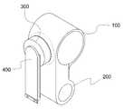
도 1 은 본 발명에 따른 자전거용 거치장치를 나타낸 사시도이며,
도 2 는 본 발명에 따른 자전거용 거치장치의 좌측면도이며,
도 3 은 본 발명에 따른 자전거용 거치장치의 정면도이며,
도 4 는 본 발명에 따른 자전거용 거치장치의 저면도이며,
도 5 는 본 발명에 따른 자전거용 거치장치의 구성을 설명하기 위한 우측면도이며,
도 6 은 본 발명에 따른 자전거용 거치장치의 구성을 설명하기 위한 분해 사시도이다.
도 7 은 본 발명에 따른 자전거용 거치장치의 추가장치 장착부의 일 실시예를 나타낸 도면이며,
도 8 은 본 발명에 따른 자전거용 거치장치의 추가장치 장착부의 제 2 실시예를 나타낸 도면이다.BRIEF DESCRIPTION OF THE DRAWINGS The accompanying drawings, which are included to provide a further understanding of the invention and are incorporated in and constitute a part of this specification, illustrate embodiments of the invention and, together with the description, serve to explain the principles of the invention.
1 is a perspective view showing a bicycle mounting apparatus according to the present invention,
2 is a left side view of the bicycle mounting apparatus according to the present invention;
3 is a front view of the bicycle mounting apparatus according to the present invention,
Figure 4 is a bottom view of the bicycle mounting apparatus according to the invention,
5 is a right side view for explaining the configuration of the bicycle mounting apparatus according to the invention,
Figure 6 is an exploded perspective view for explaining the configuration of the bicycle mounting apparatus according to the present invention.
7 is a view showing an embodiment of the additional device mounting portion of the bicycle mounting apparatus according to the present invention,
8 is a view showing a second embodiment of the additional device mounting portion of the bicycle mounting apparatus according to the present invention.
이하, 첨부된 도면을 참조하여 본 발명의 구성을 상세히 설명하기로 한다.Hereinafter, the configuration of the present invention will be described in detail with reference to the accompanying drawings.
이에 앞서, 본 명세서 및 청구범위에 사용된 용어는 사전적인 의미로 한정 해석되어서는 아니되며, 발명자는 자신의 발명을 최선의 방법으로 설명하기 위해 용어의 개념을 적절히 정의할 수 있다는 원칙에 입각하여, 본 발명의 기술적 사상에 부합되는 의미와 개념으로 해석되어야 한다.Prior to this, the terms used in the specification and claims should not be construed in a dictionary sense, and the inventor may, on the principle that the concept of a term can be properly defined in order to explain its invention in the best way And should be construed in light of the meanings and concepts consistent with the technical idea of the present invention.
따라서, 본 명세서에 기재된 실시예 및 도면에 도시된 구성은 본 발명의 바람직한 실시예에 불과할 뿐이고, 본 발명의 기술적 사상을 모두 표현하는 것은 아니므로, 본 출원 시점에 있어 이들을 대체할 수 있는 다양한 균등물과 변형예들이 존재할 수 있음을 이해하여야 한다.Therefore, the embodiments shown in the present specification and the drawings are only exemplary embodiments of the present invention, and not all of the technical ideas of the present invention are presented. Therefore, various equivalents It should be understood that water and variations may exist.
본 발명의 바람직한 실시예에 대하여 첨부된 도면을 참조하여 더 구체적으로 설명하되, 이미 주지되어 진 기술적 부분에 대해서는 설명의 간결함을 위해 생략하거나 압축하기로 한다.
The preferred embodiments of the present invention will be described in more detail with reference to the accompanying drawings, in which technical sections already known will be omitted or compressed for simplicity of explanation.
도 1 은 본 발명에 따른 자전거용 거치장치를 나타낸 사시도이며, 도 2 는 본 발명에 따른 자전거용 거치장치의 좌측면도이며, 도 3 은 본 발명에 따른 자전거용 거치장치의 정면도이며, 도 4 는 본 발명에 따른 자전거용 거치장치의 저면도이며, 도 5 는 본 발명에 따른 자전거용 거치장치의 구성을 설명하기 위한 우측면도이며, 도 6 는 본 발명에 따른 자전거용 거치장치의 구성을 설명하기 위한 분해 사시도이며, 도 7 은 본 발명에 따른 자전거용 거치장치의 추가장치 장착부의 일 실시예를 나타낸 도면이며, 도 8 은 본 발명에 따른 자전거용 거치장치의 추가장치 장착부의 제 2 실시예를 나타낸 도면이다.1 is a perspective view showing a bicycle mounting apparatus according to the present invention, Figure 2 is a left side view of the bicycle mounting apparatus according to the invention, Figure 3 is a front view of the bicycle mounting apparatus according to the invention, Figure 4 5 is a right side view for explaining the configuration of the bicycle mounting apparatus according to the present invention, Figure 6 is to explain the configuration of the bicycle mounting apparatus according to the present invention. Figure 7 is an exploded perspective view, Figure 7 is a view showing an embodiment of the mounting device for additional device of the bicycle mounting apparatus according to the present invention, Figure 8 is a second embodiment of the mounting device for additional device mounting device for a bicycle according to the invention The figure shown.
도 1 내지 도 4를 참조하면, 본 발명에 따른 자전거용 거치장치는, 자전거의 핸들바에 밀착되게 감싸는 클램프; 상기 클램프의 하단 단부와 연결되어, 추가장치를 장착할 수 있게 하는 체결공을 구비한 추가장치 장착부; 상기 클램프의 일측에 결합되어 좌우방향으로 회전이 가능한 연결부; 상기 연결부의 일측에 연결되어, 체결홈을 가지는 타 부재와 슬라이드 체결이 가능한 슬라이드 체결부; 를 포함한다.
1 to 4, the bicycle mounting apparatus according to the present invention, the clamp wraps close to the handlebar of the bicycle; An additional device mounting portion having a fastening hole connected to a lower end of the clamp to allow mounting of the additional device; A connection part coupled to one side of the clamp and rotatable in a left and right direction; A slide fastening part connected to one side of the connection part and capable of slide fastening with another member having a fastening groove; .
도 1에서와 같이, 본 발명은 클램프(100), 추가장치 장착부(200), 연결부(300), 슬라이드 체결부(400)로 구성된다.As shown in Figure 1, the present invention is composed of a
클램프(100)는 자전거용 거치장치를 자전거의 핸들바에 결합시키기 위한 장치이다. 자전거의 핸들바는 통상적으로 원형 파이프인 점에서, 클램프(100)가 전체적으로 원형의 형상을 가지며, 자전거의 핸들바를 감싸는 역할을 수행한다.The
이때, 클램프(100)는 탄성을 가지는 플라스틱 재질로 형성되는 것이 바람직하다.At this time, the
도 5를 참조하면, 클램프(100)는 체결볼트(110)와 체결홈(120)을 포함하여 형성된다.Referring to FIG. 5, the
또한, 클램프(100)는 자전거용 거치장치를 자전거의 핸들바에 안전하게 고정하기 위해서 체결볼트(110)를 사용한다.In addition, the
보다 상세하게는, 자전거용 거치장치를 자전거의 핸들바에 고정시키기 위해서는 클램프(100)의 체결볼트(110)에 대응하는 체결홈(120) 위치에 체결볼트(110)를 삽입 회전시킨다.In more detail, in order to fix the bicycle mounting apparatus to the handlebar of the bicycle, the fastening
이때, 클램프(100)와 핸들바 사이에 고정력을 높여주기 위해 고무소재의 완충패드(미도시)를 클램프 내면에 장착할 수 있다.At this time, in order to increase the fixing force between the
추가장치 장착부(200)는 클램프(100)의 하단 단부와 연결되어, 추가장치를 장착할 수 있게 도와준다.Additional
이때, 추가장치로는 라이트, 배터리, 블루투스 스피커 등이 포함될 수 있다.At this time, the additional device may include a light, a battery, a Bluetooth speaker.
여기서, 추가장치 장착부(200)는 클램프(100)와 일체로 구성될 수 있고, 탄성을 가지는 플라스틱 재질로 형성되는 것이 바람직하다.Here, the additional
여기서, 추가장치 장착부(200) 원형의 홈 크기에 맞는 막대형 블루투스 스피커, 라이트, 배터리 등 추가장치가 장착 될 수 있다.Here, the additional
도 7을 참조하면, 추가장치 장착부(200)에 블루투스 스피커가 장착된 일 실시예를 나타낸 도면이다.Referring to FIG. 7, the Bluetooth device is mounted on the additional
도 8을 참조하면, 추가장치 장착부(200)에 라이트가 장착된 제 2 실시예를 나타낸 도면이다.Referring to FIG. 8, it is a view showing a second embodiment in which a light is mounted on the additional
따라서, 추가장치 장착부(200)의 홈의 크기와 일치된다면, 어떤 장치라도 장착될 수 있다.Therefore, any device can be mounted as long as it matches the size of the groove of the additional
또한, 추가장치 장착부(200)는 내측에 가이드 홈을 형성하여, 추가장치와 결합을 용이하게 할 수 있다.In addition, the additional
그리고, 추가장치 장착부(200)와 추가장치 사이에 고정력을 높여주기 위해 고무소재의 완충패드(미도시)를 추가장치 장착부(200) 내면에 장착할 수 있다.In addition, a buffer pad (not shown) made of rubber material may be mounted on the inner surface of the additional
도 5 및 도 6을 참조하면, 연결부(300)는 제1힌지유닛(310), 제2힌지유닛(320), 힌지축을 포함하여 형성된다.5 and 6, the
연결부(300)는 클램프의 일측에 고정되어 슬라이드 체결부(400)와 연결된 부분을 회전하게 하는 역할을 수행한다.The
도 6을 참조하면, 제1힌지유닛(310)은 스토퍼(312), 제1고정부(314), 제2고정부(316)를 포함한다.Referring to FIG. 6, the
스토퍼(312)는 제2힌지유닛(320)의 톱니형 틀(322)과 대응되는 단부의 형상을 구비하여, 톱니형 틀(322)의 톱니 수에 따라 소정의 각도로 제1힌지유닛(310)이 회전하게 하는 역할을 수행한다.The
일 실시예에 따르면, 스토퍼(312)는 세 곳이 톱니형 틀(322)에 결합 되는 꼭지점이 둥근 삼각형의 모양을 형성한다.According to one embodiment, the
여기서, 제1힌지유닛(310)는 일측의 내면에 제1고정부(314)와 제2고정부(316)가 돌출된 원형 형상을 가진다.Here, the
여기서, 제1고정부(314)와 제2고정부(316)는 스토퍼(312)를 고정 시키는 역할을 수행한다.Here, the
보다 상세하게는, 스토퍼(312)는 제1고정부(314)와 제2고정부(316) 사이에 위치한다. 제1고정부(314)는 삼각형 모양인 스토퍼(312)와 결합되기 위한 홈을 가지며, 스토퍼(312)는 상기 홈에 삽입된다.More specifically, the
이때, 제2고정부(316)는 스토퍼(312)의 모양을 유지되도록 고정하는 역할을 수행한다.At this time, the
도 6을 참조하면, 제2힌지유닛(310)은 톱니형 틀(322)과 결착부(324)를 포함한다.Referring to FIG. 6, the
제2힌지유닛(320)은 제1힌지유닛(310)과 서로 대응되는 형상을 가지며, 제1힌지유닛(310)의 오목한 부분에 제2힌지유닛(320)의 볼록한 부분이 결합한다.The
여기서, 제2힌지유닛(320)은 클램프(100)의 일측에 구비되며, 내부 면에 톱니형 틀(322)을 형성한다.Here, the
여기서, 톱니형 틀(322) 내부에는 제1고정부(314)와 제2고정부(316) 사이의 오목한 부분 대응하여 결합되는 돌출된 형상을 가진 결착부(324)를 형성한다.Here, in the
이때, 결착부(324)는 스토퍼(312)와 제2고정부(316)가 형성하는 공간에 삽입되는 형상을 가진다.At this time, the binding
힌지축(330)은 결착부(324)와 제2고정부(316)의 홈에 삽입되어 제1힌지유닛(310)과 제2힌지유닛(320)을 연결시키는 역할을 수행한다.The
따라서, 제1힌지유닛(310)을 좌우로 힘을 가하면 제2힌지유닛(320)의 톱니형 틀(322)에 맞게 스토퍼(312)가 맞물려, 제1힌지유닛(310)이 회전하게 된다.Accordingly, when a force is applied to the
슬라이드 체결부(400)는 체결홈을 가지는 타 부재와 슬라이드 체결이 가능하는 역할을 수행한다.The
보다 상세하게는, 슬라이드 체결부(400) 전면은, 슬라이드 체결을 할 수 있도록 하부면에서 상부 방향으로 뚫린 직사각형 형태의 체결홈을 가진 타 부재와 체결하기 위한 돌출된 구조를 형성한다.More specifically, the front surface of the
여기서, 슬라이드 체결부(400) 배면은 중앙 부분만 돌출되고 양 측부는 오목한 구조를 형성한다.
Here, the back surface of the
전술한 바와 같이, 본 발명에 의해, 휴대용 통신기기를 자전거용 거치장치에 장착한 상태에서 좌우방향으로 회전이 가능하다.As described above, according to the present invention, the portable communication device can be rotated in the horizontal direction in a state where the portable communication device is mounted.
또한, 자전거용 거치장치에 동시에 2개의 악세서리를 장착할 수 있어, 핸들바의 제한된 장착위치 한계점을 극복할 수 있다.
In addition, two accessories can be mounted on the bike mounting device at the same time, thereby overcoming the limited mounting position limitations of the handlebars.
이상, 본 발명은 비록 한정된 실시예와 도면에 의해 설명되었으나, 본 발명의 기술적 사상은 이러한 것에 한정되지 않으며, 본 발명이 속하는 기술분야에서 통상의 지식을 가진 자에 의해, 본 발명의 기술적 사상과 하기 될 특허청구범위의 균등범위 내에서 다양한 수정 및 변형 실시가 가능할 것이다.While the present invention has been described with reference to the exemplary embodiments and the drawings, it is to be understood that the technical scope of the present invention is not limited to these embodiments and that various changes and modifications will be apparent to those skilled in the art. Various modifications and variations may be made without departing from the scope of the appended claims.
*도면의 주요부분에 대한 부호의 설명*
100 : 클램프
110 : 체결볼트
120 : 체결홈
200 : 추가장치 장착부
300 : 연결부
310 : 제1힌지유닛
312 : 스토퍼
314 : 제1고정부
316 : 제2고정부
320 : 제2힌지유닛
322 : 톱니형 틀
324 : 결착부
330 : 힌지축
400 : 슬라이드 체결부Description of the Related Art [0002]
100: clamp
110: fastening bolt
120: fastening groove
200: additional device mounting portion
300: connection
310: first hinge unit
312: stopper
314: First Government
316: Second Government
320: second hinge unit
322: serrated frame
324: binding
330: hinge axis
400: slide fastener
Claims (2)
Translated fromKorean상기 클램프의 하단 단부와 연결되어, 라이트, 배터리, 블루투스 스피커 등의 추가장치를 장착할 수 있게 하는 체결공을 구비한 추가장치 장착부;
상기 클램프의 일측에 결합되어 좌우방향으로 회전이 가능한 연결부;
상기 연결부의 일측에 연결되어, 체결홈을 가지는 타 부재와 슬라이드 체결이 가능한 슬라이드 체결부; 를 포함하는 것을 특징으로 하는
자전거용 거치장치.A clamp wrapped close to the handlebar of the bicycle;
An additional device mounting part having a fastening hole connected to the lower end of the clamp and allowing the additional device such as a light, a battery, and a Bluetooth speaker to be mounted;
A connection part coupled to one side of the clamp and rotatable in a left and right direction;
A slide fastening part connected to one side of the connection part and capable of slide fastening with another member having a fastening groove; ≪ RTI ID = 0.0 >
Bicycle mounting device.
상기 연결부는, 상기 연결부의 타측에 스토퍼, 상기 스토퍼를 고정시키는 역할을 하는 제1고정부 및 제2고정부를 구비한 제1힌지유닛; 상기 스토퍼와 맞물리는 톱니형 틀과 상기 톱니형 틀 내부에 상기 제1힌지유닛과 대응되는 구조를 가진 결착부를 구비한 제2힌지유닛;을 포함하여, 상기 제1힌지유닛의 스토퍼가 상기 제2힌지유닛의 상기 톱니형 틀과 맞물리면서 상기 연결부가 미리 설정된 각도로 회전하는 것을 특징으로 하는
자전거용 거치장치.The method of claim 1,
The connecting unit may include: a first hinge unit having a stopper and a second fixing part serving to fix the stopper and the stopper on the other side of the connecting part; And a second hinge unit having a sawtooth frame engaged with the stopper and a binding portion having a structure corresponding to the first hinge unit inside the sawtooth frame, wherein the stopper of the first hinge unit includes the second hinge unit. The connecting portion rotates at a predetermined angle while being engaged with the serrated frame of the hinge unit.
Bicycle mounting device.
Priority Applications (1)
| Application Number | Priority Date | Filing Date | Title |
|---|---|---|---|
| KR1020120073326AKR101371132B1 (en) | 2012-07-05 | 2012-07-05 | Bicycle mount device |
Applications Claiming Priority (1)
| Application Number | Priority Date | Filing Date | Title |
|---|---|---|---|
| KR1020120073326AKR101371132B1 (en) | 2012-07-05 | 2012-07-05 | Bicycle mount device |
Publications (2)
| Publication Number | Publication Date |
|---|---|
| KR20140006431A KR20140006431A (en) | 2014-01-16 |
| KR101371132B1true KR101371132B1 (en) | 2014-03-07 |
Family
ID=50141358
Family Applications (1)
| Application Number | Title | Priority Date | Filing Date |
|---|---|---|---|
| KR1020120073326AExpired - Fee RelatedKR101371132B1 (en) | 2012-07-05 | 2012-07-05 | Bicycle mount device |
Country Status (1)
| Country | Link |
|---|---|
| KR (1) | KR101371132B1 (en) |
Cited By (1)
| Publication number | Priority date | Publication date | Assignee | Title |
|---|---|---|---|---|
| KR101645609B1 (en) | 2015-12-07 | 2016-08-08 | 서형바이클랙주식회사 | a locking apparatus and bike parking apparatus having the same |
Families Citing this family (1)
| Publication number | Priority date | Publication date | Assignee | Title |
|---|---|---|---|---|
| JP7061102B2 (en)* | 2019-10-18 | 2022-04-27 | 本田技研工業株式会社 | Saddle-type vehicle |
Citations (2)
| Publication number | Priority date | Publication date | Assignee | Title |
|---|---|---|---|---|
| KR200416386Y1 (en)* | 2006-03-03 | 2006-05-15 | 황필상 | Bicycle mobile terminal holder |
| KR101124166B1 (en)* | 2009-12-04 | 2012-03-27 | 손대업 | Clamp apparatus for light |
- 2012
- 2012-07-05KRKR1020120073326Apatent/KR101371132B1/ennot_activeExpired - Fee Related
Patent Citations (2)
| Publication number | Priority date | Publication date | Assignee | Title |
|---|---|---|---|---|
| KR200416386Y1 (en)* | 2006-03-03 | 2006-05-15 | 황필상 | Bicycle mobile terminal holder |
| KR101124166B1 (en)* | 2009-12-04 | 2012-03-27 | 손대업 | Clamp apparatus for light |
Cited By (2)
| Publication number | Priority date | Publication date | Assignee | Title |
|---|---|---|---|---|
| KR101645609B1 (en) | 2015-12-07 | 2016-08-08 | 서형바이클랙주식회사 | a locking apparatus and bike parking apparatus having the same |
| WO2017099396A1 (en) | 2015-12-07 | 2017-06-15 | 서형바이클랙 주식회사 | Locking device and bicycle storing device having same |
Also Published As
| Publication number | Publication date |
|---|---|
| KR20140006431A (en) | 2014-01-16 |
Similar Documents
| Publication | Publication Date | Title |
|---|---|---|
| US9402016B1 (en) | Electronic device mount | |
| US9368999B2 (en) | Wireless charging structure for mobile information terminal in vehicle | |
| KR101279536B1 (en) | Bicycle's mobile phone holder | |
| US9592874B2 (en) | Intelligent bicycle | |
| US20160288875A1 (en) | Bicycle battery holder and bicycle battery unit | |
| CN110061161A (en) | Battery holder | |
| US9764788B1 (en) | Compound vibration absorption assembly for bike saddle | |
| TW201700336A (en) | Bicycle frame with reinforced motor mount | |
| RU2016114536A (en) | ELECTRIC BYCICLE | |
| KR101371132B1 (en) | Bicycle mount device | |
| JP6941493B2 (en) | Bicycle battery unit and module | |
| KR20120006361U (en) | multi-function smart-phone holder | |
| JP7442361B2 (en) | Charging structure for saddle-type vehicles | |
| JP6175217B2 (en) | Charging structure of portable information terminal | |
| KR100989374B1 (en) | Bicycle Umbrella Mounter | |
| NO20050516D0 (en) | Bicycle attachment device | |
| CN108605068A (en) | The mobile phones universal fixing device detachably rotated | |
| KR200483798Y1 (en) | Multi-purpose mobile phone cover cradle | |
| AU2016265034A1 (en) | Bicycle helmet | |
| KR20130002954U (en) | Mobile holders for a two-wheeled vehicle | |
| JP2015024703A (en) | Function extension mechanism of handlebar for motorcycle | |
| KR20150106512A (en) | An electric bicycle which has frame inserted battery pack | |
| US20030137850A1 (en) | Light device for bicycles | |
| KR200471572Y1 (en) | holder for portable terminal | |
| KR101229675B1 (en) | Multimedia terminal holding apparatus for motorcycle |
Legal Events
| Date | Code | Title | Description |
|---|---|---|---|
| A201 | Request for examination | ||
| PA0109 | Patent application | St.27 status event code:A-0-1-A10-A12-nap-PA0109 | |
| PA0201 | Request for examination | St.27 status event code:A-1-2-D10-D11-exm-PA0201 | |
| E902 | Notification of reason for refusal | ||
| PE0902 | Notice of grounds for rejection | St.27 status event code:A-1-2-D10-D21-exm-PE0902 | |
| P11-X000 | Amendment of application requested | St.27 status event code:A-2-2-P10-P11-nap-X000 | |
| P13-X000 | Application amended | St.27 status event code:A-2-2-P10-P13-nap-X000 | |
| PG1501 | Laying open of application | St.27 status event code:A-1-1-Q10-Q12-nap-PG1501 | |
| E701 | Decision to grant or registration of patent right | ||
| PE0701 | Decision of registration | St.27 status event code:A-1-2-D10-D22-exm-PE0701 | |
| GRNT | Written decision to grant | ||
| PR0701 | Registration of establishment | St.27 status event code:A-2-4-F10-F11-exm-PR0701 | |
| PR1002 | Payment of registration fee | St.27 status event code:A-2-2-U10-U11-oth-PR1002 Fee payment year number:1 | |
| PG1601 | Publication of registration | St.27 status event code:A-4-4-Q10-Q13-nap-PG1601 | |
| PR1001 | Payment of annual fee | St.27 status event code:A-4-4-U10-U11-oth-PR1001 Fee payment year number:4 | |
| PN2301 | Change of applicant | St.27 status event code:A-5-5-R10-R13-asn-PN2301 St.27 status event code:A-5-5-R10-R11-asn-PN2301 | |
| P22-X000 | Classification modified | St.27 status event code:A-4-4-P10-P22-nap-X000 | |
| LAPS | Lapse due to unpaid annual fee | ||
| PC1903 | Unpaid annual fee | St.27 status event code:A-4-4-U10-U13-oth-PC1903 Not in force date:20180301 Payment event data comment text:Termination Category : DEFAULT_OF_REGISTRATION_FEE | |
| PC1903 | Unpaid annual fee | St.27 status event code:N-4-6-H10-H13-oth-PC1903 Ip right cessation event data comment text:Termination Category : DEFAULT_OF_REGISTRATION_FEE Not in force date:20180301 | |
| P22-X000 | Classification modified | St.27 status event code:A-4-4-P10-P22-nap-X000 |