KR101370889B1 - Digital broadcasting system and processing method - Google Patents
Digital broadcasting system and processing methodDownload PDFInfo
- Publication number
- KR101370889B1 KR101370889B1KR1020050132489AKR20050132489AKR101370889B1KR 101370889 B1KR101370889 B1KR 101370889B1KR 1020050132489 AKR1020050132489 AKR 1020050132489AKR 20050132489 AKR20050132489 AKR 20050132489AKR 101370889 B1KR101370889 B1KR 101370889B1
- Authority
- KR
- South Korea
- Prior art keywords
- data
- enhanced
- main
- parity
- packet
- Prior art date
- Legal status (The legal status is an assumption and is not a legal conclusion. Google has not performed a legal analysis and makes no representation as to the accuracy of the status listed.)
- Expired - Fee Related
Links
Images


Classifications
- H—ELECTRICITY
- H04—ELECTRIC COMMUNICATION TECHNIQUE
- H04L—TRANSMISSION OF DIGITAL INFORMATION, e.g. TELEGRAPHIC COMMUNICATION
- H04L1/00—Arrangements for detecting or preventing errors in the information received
- H04L1/004—Arrangements for detecting or preventing errors in the information received by using forward error control
- H04L1/0041—Arrangements at the transmitter end
- H—ELECTRICITY
- H03—ELECTRONIC CIRCUITRY
- H03M—CODING; DECODING; CODE CONVERSION IN GENERAL
- H03M13/00—Coding, decoding or code conversion, for error detection or error correction; Coding theory basic assumptions; Coding bounds; Error probability evaluation methods; Channel models; Simulation or testing of codes
- H03M13/25—Error detection or forward error correction by signal space coding, i.e. adding redundancy in the signal constellation, e.g. Trellis Coded Modulation [TCM]
- H—ELECTRICITY
- H03—ELECTRONIC CIRCUITRY
- H03M—CODING; DECODING; CODE CONVERSION IN GENERAL
- H03M13/00—Coding, decoding or code conversion, for error detection or error correction; Coding theory basic assumptions; Coding bounds; Error probability evaluation methods; Channel models; Simulation or testing of codes
- H03M13/27—Coding, decoding or code conversion, for error detection or error correction; Coding theory basic assumptions; Coding bounds; Error probability evaluation methods; Channel models; Simulation or testing of codes using interleaving techniques
- H—ELECTRICITY
- H04—ELECTRIC COMMUNICATION TECHNIQUE
- H04L—TRANSMISSION OF DIGITAL INFORMATION, e.g. TELEGRAPHIC COMMUNICATION
- H04L1/00—Arrangements for detecting or preventing errors in the information received
- H04L1/004—Arrangements for detecting or preventing errors in the information received by using forward error control
- H04L1/0045—Arrangements at the receiver end
- H—ELECTRICITY
- H04—ELECTRIC COMMUNICATION TECHNIQUE
- H04L—TRANSMISSION OF DIGITAL INFORMATION, e.g. TELEGRAPHIC COMMUNICATION
- H04L1/00—Arrangements for detecting or preventing errors in the information received
- H04L1/004—Arrangements for detecting or preventing errors in the information received by using forward error control
- H04L1/0056—Systems characterized by the type of code used
- H04L1/0057—Block codes
- H—ELECTRICITY
- H04—ELECTRIC COMMUNICATION TECHNIQUE
- H04L—TRANSMISSION OF DIGITAL INFORMATION, e.g. TELEGRAPHIC COMMUNICATION
- H04L1/00—Arrangements for detecting or preventing errors in the information received
- H04L1/004—Arrangements for detecting or preventing errors in the information received by using forward error control
- H04L1/0056—Systems characterized by the type of code used
- H04L1/007—Unequal error protection
- H—ELECTRICITY
- H04—ELECTRIC COMMUNICATION TECHNIQUE
- H04L—TRANSMISSION OF DIGITAL INFORMATION, e.g. TELEGRAPHIC COMMUNICATION
- H04L1/00—Arrangements for detecting or preventing errors in the information received
- H04L1/004—Arrangements for detecting or preventing errors in the information received by using forward error control
- H04L1/0056—Systems characterized by the type of code used
- H04L1/0071—Use of interleaving
- H—ELECTRICITY
- H04—ELECTRIC COMMUNICATION TECHNIQUE
- H04L—TRANSMISSION OF DIGITAL INFORMATION, e.g. TELEGRAPHIC COMMUNICATION
- H04L27/00—Modulated-carrier systems
- H04L27/02—Amplitude-modulated carrier systems, e.g. using on-off keying; Single sideband or vestigial sideband modulation
- H—ELECTRICITY
- H04—ELECTRIC COMMUNICATION TECHNIQUE
- H04N—PICTORIAL COMMUNICATION, e.g. TELEVISION
- H04N21/00—Selective content distribution, e.g. interactive television or video on demand [VOD]
- H04N21/20—Servers specifically adapted for the distribution of content, e.g. VOD servers; Operations thereof
- H04N21/23—Processing of content or additional data; Elementary server operations; Server middleware
- H04N21/235—Processing of additional data, e.g. scrambling of additional data or processing content descriptors
- H—ELECTRICITY
- H04—ELECTRIC COMMUNICATION TECHNIQUE
- H04N—PICTORIAL COMMUNICATION, e.g. TELEVISION
- H04N21/00—Selective content distribution, e.g. interactive television or video on demand [VOD]
- H04N21/20—Servers specifically adapted for the distribution of content, e.g. VOD servers; Operations thereof
- H04N21/23—Processing of content or additional data; Elementary server operations; Server middleware
- H04N21/238—Interfacing the downstream path of the transmission network, e.g. adapting the transmission rate of a video stream to network bandwidth; Processing of multiplex streams
- H04N21/2383—Channel coding or modulation of digital bit-stream, e.g. QPSK modulation
- H—ELECTRICITY
- H04—ELECTRIC COMMUNICATION TECHNIQUE
- H04N—PICTORIAL COMMUNICATION, e.g. TELEVISION
- H04N21/00—Selective content distribution, e.g. interactive television or video on demand [VOD]
- H04N21/40—Client devices specifically adapted for the reception of or interaction with content, e.g. set-top-box [STB]; Operations thereof
- H04N21/43—Processing of content or additional data, e.g. demultiplexing additional data from a digital video stream; Elementary client operations, e.g. monitoring of home network or synchronising decoder's clock; Client middleware
- H04N21/435—Processing of additional data, e.g. decrypting of additional data, reconstructing software from modules extracted from the transport stream
- H—ELECTRICITY
- H04—ELECTRIC COMMUNICATION TECHNIQUE
- H04N—PICTORIAL COMMUNICATION, e.g. TELEVISION
- H04N21/00—Selective content distribution, e.g. interactive television or video on demand [VOD]
- H04N21/40—Client devices specifically adapted for the reception of or interaction with content, e.g. set-top-box [STB]; Operations thereof
- H04N21/43—Processing of content or additional data, e.g. demultiplexing additional data from a digital video stream; Elementary client operations, e.g. monitoring of home network or synchronising decoder's clock; Client middleware
- H04N21/438—Interfacing the downstream path of the transmission network originating from a server, e.g. retrieving encoded video stream packets from an IP network
- H04N21/4382—Demodulation or channel decoding, e.g. QPSK demodulation
- H—ELECTRICITY
- H03—ELECTRONIC CIRCUITRY
- H03M—CODING; DECODING; CODE CONVERSION IN GENERAL
- H03M13/00—Coding, decoding or code conversion, for error detection or error correction; Coding theory basic assumptions; Coding bounds; Error probability evaluation methods; Channel models; Simulation or testing of codes
- H03M13/27—Coding, decoding or code conversion, for error detection or error correction; Coding theory basic assumptions; Coding bounds; Error probability evaluation methods; Channel models; Simulation or testing of codes using interleaving techniques
- H03M13/2732—Convolutional interleaver; Interleavers using shift-registers or delay lines like, e.g. Ramsey type interleaver
- H—ELECTRICITY
- H04—ELECTRIC COMMUNICATION TECHNIQUE
- H04L—TRANSMISSION OF DIGITAL INFORMATION, e.g. TELEGRAPHIC COMMUNICATION
- H04L1/00—Arrangements for detecting or preventing errors in the information received
- H04L1/004—Arrangements for detecting or preventing errors in the information received by using forward error control
- H04L1/0056—Systems characterized by the type of code used
- H04L1/0059—Convolutional codes
- H04L1/006—Trellis-coded modulation
Landscapes
- Engineering & Computer Science (AREA)
- Signal Processing (AREA)
- Computer Networks & Wireless Communication (AREA)
- Multimedia (AREA)
- Theoretical Computer Science (AREA)
- Probability & Statistics with Applications (AREA)
- Physics & Mathematics (AREA)
- Two-Way Televisions, Distribution Of Moving Picture Or The Like (AREA)
- Error Detection And Correction (AREA)
- Circuits Of Receivers In General (AREA)
- Data Exchanges In Wide-Area Networks (AREA)
- Detection And Prevention Of Errors In Transmission (AREA)
- Mobile Radio Communication Systems (AREA)
- Traffic Control Systems (AREA)
Abstract
Translated fromKorean
Description
Translated fromKorean도 1은 본 발명의 일 실시예에 따른 디지털 방송 송신 시스템의 구성 블록도1 is a block diagram illustrating a digital broadcast transmission system according to an embodiment of the present invention.
도 2는 도 1의 트렐리스 부호화부의 일 실시예를 보인 구성 블록도FIG. 2 is a block diagram illustrating an embodiment of the trellis encoder of FIG. 1.
도 3은 도 2의 데이터 인터리버의 구조의 일 실시예를 보인 구성 블록도3 is a block diagram illustrating an embodiment of a structure of a data interleaver of FIG.
도 4는 VSB 프레임에서 데이터 인터리버의 출력 순서의 예를 보인 도면4 shows an example of an output order of a data interleaver in a VSB frame.
도 5의 (a),(b)는 본 발명의 기지 데이터 삽입에 따른 데이터 인터리버 전후단의 데이터 구성 예를 보인 도면5 (a) and 5 (b) are diagrams showing an example of the data configuration of the front and rear ends of the data interleaver according to the known data insertion according to the present invention.
도 6a 내지 도 6c는 본 발명의 4 데이터 세그먼트 주기로 기지 데이터를 삽입함에 따른 데이터 인터리버 전후단의 바이트 영역에서와 심볼 영역에서의 데이터 구성 예를 보인 도면6A through 6C are diagrams showing an example of data configuration in a byte area and a symbol area before and after the data interleaver according to inserting known data in four data segment periods of the present invention.
도 7a 내지 도 7c는 본 발명의 5 세그먼트 주기로 기지 데이터를 삽입함에 따른 데이터 인터리버 전후단의 바이트 영역에서와 심볼 영역에서의 데이터 구성 예를 보인 도면7A to 7C are diagrams showing an example of data configuration in a byte area and a symbol area before and after the data interleaver by inserting known data in a 5-segment period of the present invention.
도 8a 내지 도 8c는 본 발명의 8 세그먼트 주기로 기지 데이터를 삽입함에 따른 데이터 인터리버 전후단의 바이트 영역에서와 심볼 영역에서의 데이터 구성 예를 보인 도면8A to 8C are diagrams showing an example of data configuration in a byte area and a symbol area before and after the data interleaver according to inserting known data in 8 segment periods of the present invention.
도 9는 본 발명에 따른 디지털 방송 수신 시스템의 일 실시예를 보인 전체 구성 블록도9 is a block diagram showing the overall configuration of an embodiment of a digital broadcast receiving system according to the present invention.
도면의 주요부분에 대한 부호의 설명DESCRIPTION OF THE REFERENCE NUMERALS
101 : E-VSB 전처리부102 : E-VSB 패킷 포맷터101: E-VSB preprocessor 102: E-VSB packet formatter
103 : 패킷 다중화기104 : 데이터 랜더마이저103: packet multiplexer 104: data randomizer
105 : 스케쥴러110 : E-VSB 후처리부105: scheduler 110: E-VSB post-processing unit
111,121 : RS 부호기 및 비체계적 RS 패리티 위치 홀더 삽입부111,121: RS encoder and unstructured RS parity position holder insert
112,122 : 데이터 인터리버113 : E-VSB 길쌈 부호화기112,122: data interleaver 113: E-VSB convolutional encoder
114 : 데이터 디인터리버115 : RS 바이트 제거기114: data deinterleaver 115: RS byte remover
123 : 트렐리스 부호화부130 : 호환성 처리부123: trellis encoder 130: compatibility processor
140 : 프레임 다중화기150 : 송신부140: frame multiplexer 150: transmitter
본 발명은 디지털 통신 시스템에 관한 것으로, 특히 VSB(Vestigial Side Band) 방식으로 변조하여 이를 송신하고 수신하는 디지털 방송 시스템, 및 처리 방법에 관한 것이다.BACKGROUND OF THE
북미 및 국내에서 디지털 방송 표준으로 채택된 8T-VSB 전송방식은 MPEG 영상/음향 데이터의 전송을 위해 개발된 시스템이다. 그러나 요즈음 디지털 신호처리 기술이 급속도로 발전하고, 인터넷이 널리 사용됨에 따라서 디지털 가전과 컴퓨터 및 인터넷 등이 하나의 큰 틀에 통합되어 가는 추세이다. 따라서 사용자의 다양한 요구를 충족시키기 위해서는 디지털 방송 채널을 통하여 영상/음향 데이터에 더하여 각종 부가 데이터를 전송할 수 있는 시스템의 개발이 필요하다.The 8T-VSB transmission system, adopted as a digital broadcasting standard in North America and Korea, is a system developed for transmission of MPEG video / audio data. However, with the rapid development of digital signal processing technology and the widespread use of the Internet, digital home appliances, computers, and the Internet are being integrated into one big framework. Therefore, in order to meet various needs of users, it is necessary to develop a system capable of transmitting various additional data in addition to video / audio data through a digital broadcasting channel.
부가 데이터 방송의 일부 이용자는 간단한 형태의 실내 안테나가 부착된 PC 카드 혹은 포터블 기기를 이용하여 부가데이터방송을 사용할 것으로 예측되는데, 실내에서는 벽에 의한 차단과 근접 이동체의 영향으로 신호 세기가 크게 감소하고 반사파로 인한 고스트와 잡음의 영향으로 방송 수신 성능이 떨어지는 경우가 발생할 수 있다. 그런데 일반적인 영상/음향데이터와는 달리 부가 데이터 전송의 경우에는 보다 낮은 오류율을 가져야 한다. 영상/음향 데이터의 경우에는 사람의 눈과 귀가 감지하지 못하는 정도의 오류는 문제가 되지 않는 반면에, 부가데이터(예: 프로그램 실행 파일, 주식 정보 등)의 경우에는 한 비트의 오류가 발생해도 심각한 문제를 일으킬 수 있다. 따라서채널에서 발생하는 고스트와 잡음에 더 강한 시스템의 개발이 필요하다.Some users of supplementary data broadcasting are expected to use supplementary data broadcasting by using PC card or portable device with simple indoor antenna. In the room, signal strength is greatly reduced due to wall blocking and influence of nearby moving objects. Due to the effects of ghosts and noise caused by reflected waves, broadcast reception performance may deteriorate. However, unlike general video / audio data, the additional data transmission should have a lower error rate. In the case of video / audio data, errors that the human eye and ears cannot detect are not a problem, while in the case of additional data (eg program executables, stock information, etc.), a bit error may cause serious problems. It can cause problems. therefore There is a need to develop a system that is more resistant to ghosting and noise in the channel.
부가 데이터의 전송은 통상 MPEG 영상/음향과 동일한 채널을 통해 시분할 방식으로 이루어 질 것이다. 그런데 디지털 방송이 시작된 이후로 시장에는 이미 MPEG 영상/음향만 수신하는 ATSC VSB 디지털 방송 수신기가 널리 보급되어 있는 상황이다. 따라서 MPEG 영상/음향과 동일한 채널로 전송되는 부가 데이터가 기존에 시장에 보급된 기존 ATSC VSB 전용 수신기에 아무런 영향을 주지 않아야 한다. 이와 같은 상황을 ATSC VSB 호환으로 정의하며, 부가데이터 방송 시스템은 ATSC VSB 시스템과 호환 가능한 시스템이어야 할 것이다. 상기 부가 데이터를 인핸스드 데이 터 또는 E-VSB 데이터라 하기도 한다.The transmission of additional data will usually be done in a time division manner over the same channel as the MPEG video / sound. Since the beginning of digital broadcasting, however, ATSC VSB digital broadcasting receivers that receive only MPEG video / audio have been widely used in the market. Therefore, additional data transmitted on the same channel as MPEG video / audio should not affect the existing ATSC VSB-only receivers that have been used in the market. Such a situation is defined as ATSC VSB compatible, and the additional data broadcasting system should be compatible with the ATSC VSB system. The additional data may also be referred to as enhanced data or E-VSB data.
또한 열악한 채널환경에서는 기존의 ATSC VSB 수신 시스템의 수신성능이 떨어질 수 있다. 특히 휴대용 및 이동수신기의 경우에는 채널변화 및 노이즈에 대한 강건성이 더욱 요구된다.In addition, in a poor channel environment, the reception performance of the conventional ATSC VSB receiving system may be degraded. Especially in the case of portable and mobile receivers, robustness against channel changes and noise is required.
따라서 본 발명의 목적은 부가데이터 전송에 적합하고 노이즈에 강한 새로운 디지털 방송 시스템을 제공하는데 있다.Accordingly, an object of the present invention is to provide a new digital broadcasting system suitable for additional data transmission and resistant to noise.
본 발명의 다른 목적은 송/수신측에서 알고 있는 기지 데이터(Known data)를 데이터 구간의 소정 영역에 삽입하여 전송함으로써, 수신 성능을 향상시키는 방송 시스템 및 방법을 제공하는데 있다.Another object of the present invention is to provide a broadcast system and method for improving reception performance by inserting and transmitting known data known to the transmitting / receiving side into a predetermined region of a data section.
본 발명의 또 다른 목적은 기지 데이터를 포함하는 인핸스드 데이터에 대해 비체계적 RS 부호화를 수행함으로써, 기지 데이터 삽입이 효율적으로 이루어지는 방송 시스템 및 방법을 제공하는데 있다.It is still another object of the present invention to provide a broadcast system and method for efficiently inserting known data by performing unsystematic RS encoding on enhanced data including known data.
상기 목적을 달성하기 위하여, 본 발명에 따른 디지털 방송 처리 방법은,In order to achieve the above object, the digital broadcast processing method according to the present invention,
(a) 연속하는 다수개의 인핸스드 데이터 패킷을 그룹화하고, 데이터 인터리빙 후의 심볼 영역에서 기지 데이터의 열이 일정한 간격으로 삽입되어 출력되도록 상기 그룹 내 기지 데이터 열의 위치를 결정하는 단계;(a) grouping a plurality of consecutive enhanced data packets, and determining a position of the known data strings in the group such that the columns of known data are inserted and output at regular intervals in the symbol region after data interleaving;
(b) 상기 기지 데이터의 위치가 결정되면 데이터 인터리빙 후의 데이터 출력 순서를 기준으로 상기 기지 데이터 열의 시작 부분에 트렐리스 부호기의 메모리 초 기화를 위한 기지 데이터 위치를 결정하는 단계;(b) determining a known data position for memory initialization of a trellis encoder at the beginning of the known data sequence based on the data output order after data interleaving if the position of the known data is determined;
(c) 데이터 인터리빙 후의 데이터 출력 순서에서 상기 초기화를 위한 기지 데이터보다 나중에 전송되도록 비체계적 RS 패리티 위치를 결정하는 단계; 및(c) determining an unstructured RS parity position to be sent later than the known data for initialization in the data output order after data interleaving; And
(d) 상기 인핸스드 데이터 패킷에 대해 비체계적 RS 부호화를 수행하는 단계를 포함하여 이루어지는 것을 특징으로 한다.(d) performing unsystematic RS coding on the enhanced data packet.
상기 그룹 내 기지 데이터 열이 삽입되는 간격은 데이터 인터리빙 후 심볼 영역에서 데이터 세그먼트 길이의 정수배인 것을 특징으로 한다.The interval at which the known data strings are inserted in the group is an integer multiple of the data segment length in the symbol region after data interleaving.
상기 일정한 간격으로 삽입되는 기지 데이터 열은 서로 동일한 것을 특징으로 한다.The known data strings inserted at regular intervals are identical to each other.
상기 일정한 간격으로 삽입되는 기지 데이터 심볼 열 중간에 세그먼트 동기 심볼이 삽입되는 경우 항상 일정한 위치에 삽입되는 것을 특징으로 한다.When a segment sync symbol is inserted in the middle of the known data symbol string inserted at regular intervals, the segment sync symbol is always inserted at a constant position.
본 발명의 다른 실시예에 따른 디지털 방송 처리 방법은,Digital broadcast processing method according to another embodiment of the present invention,
(a) 인핸스드 데이터와 기지 데이터 중 적어도 하나가 포함되는 연속하는 다수개의 인핸스드 데이터 패킷을 그룹화하고, 데이터 인터리빙 후의 심볼 영역에서 기지 데이터의 열이 일정한 간격으로 삽입되어 출력되도록 상기 그룹 내 기지 데이터 열의 위치를 결정하는 단계;(a) grouping a plurality of successive enhanced data packets including at least one of enhanced data and known data, and inserting and outputting columns of known data at regular intervals in the symbol region after data interleaving; Determining the location of the columns;
(b) 입력되는 인핸스드 데이터 패킷에 대해서 다수개의 비체계적 RS 패리티 또는 RS 패리티 위치 홀더를 삽입한 후 데이터 인터리빙을 수행하는 단계;
(c) 상기 데이터 인터리빙되어 출력되는 데이터가 기지 데이터이고, 연속되는 기지 데이터열의 처음이면 메모리 초기화를 수행한 후 트렐리스 부호화하여 출력하는 단계; 및(b) inserting a plurality of unstructured RS parity or RS parity position holders into the received enhanced data packet and performing data interleaving;
(c) trellis encoding and outputting the data interleaved and outputted as known data and performing a memory initialization if the data is the first known data sequence; And
삭제delete
(d) 상기 데이터 인터리빙 전의 인핸스드 데이터 패킷 내 데이터와 트렐리스 부호기의 메모리 초기화를 위한 데이터를 이용하여 비체계적 RS 패리티를 계산한 후 상기 비체계적 RS 패리티 또는 RS 패리티 위치 홀더를 치환하여 트렐리스 부호화를 수행하는 단계를 포함하여 이루어지는 것을 특징으로 한다.(d) calculating an unstructured RS parity using data in the enhanced data packet before data interleaving and data for memory initialization of the trellis encoder, and then replacing the unstructured RS parity or RS parity position holder and trellis. And performing step encoding.
본 발명에 따른 디지털 방송 처리 방법은, 상기 (a) 단계에서 입력되는 인핸스드 데이터 패킷에 대해서 다수개의 RS 패리티 위치 홀더를 삽입한 후 데이터 인터리빙을 수행하는 단계와, 상기 데이터 인터리빙되어 출력되는 인핸스드 데이터 패킷 내 인핸스드 데이터에 대해서만 추가의 부호화를 수행하고, 그 외의 데이터는 추가의 부호화를 수행하지 않고 출력하는 단계와, 상기 단계에서 출력되는 인핸스드 데이터 패킷에 대해 데이터 디인터리빙한 후 RS 패리티 위치 홀더를 제거하여 상기 (b) 단계로 출력하는 단계를 더 포함하여 이루어지는 것을 특징으로 한다.The digital broadcasting processing method according to the present invention comprises inserting a plurality of RS parity position holders into an enhanced data packet input in the step (a) and performing data interleaving, and the data being interleaved and outputted. Performing additional encoding only on the enhanced data in the data packet, and outputting other data without performing further encoding; and RS parity position after data deinterleaving for the enhanced data packet output in the step. And removing the holder and outputting the step (b).
본 발명에 따른 디지털 방송 송신 시스템은, 인핸스드 데이터와 기지 데이터 중 적어도 하나가 포함되는 연속하는 다수개의 인핸스드 데이터 패킷을 그룹화하고, 데이터 인터리빙 후의 심볼 영역에서 기지 데이터의 열이 일정한 간격으로 삽입되어 출력되도록 상기 그룹 내 기지 데이터 열의 위치를 결정하며, 상기 인핸스드 데이터 패킷 그룹과 메인 데이터 패킷을 다중화하는 E-VSB 패킷 포맷터 및 다중화기; 상기 E-VSB 패킷 포맷터 및 다중화기의 출력에 대해 다수개의 RS 패리티 위치 홀더를 삽입하여 데이터 인터리빙을 수행하고, 인터리빙된 데이터가 인핸스드 데이터인 경우에만 추가의 부호화를 수행한 후, 데이터 디인터리빙과 RS 패리티 위치 홀더 제거를 수행하는 E-VSB 후처리부; 및 상기 E-VSB 후처리부의 출력에 대해 다수개의 비체계적 RS 패리티 또는 RS 패리티 위치 홀더를 삽입하여 데이터 인터리빙을 수행한 후 트렐리스 부호화를 위해 출력하는 비체계적 RS 패리티 위치 홀더 삽입부 및 데이터 인터리버를 포함하여 구성되는 것을 특징으로 한다.In the digital broadcasting transmission system according to the present invention, a plurality of consecutive enhanced data packets including at least one of enhanced data and known data are grouped, and a column of known data is inserted at regular intervals in a symbol region after data interleaving. An E-VSB packet formatter and a multiplexer for determining a position of the known data stream in the group to be output, and multiplexing the enhanced data packet group and the main data packet; Data interleaving is performed by inserting a plurality of RS parity position holders into the outputs of the E-VSB packet formatter and the multiplexer, and further performing encoding only when the interleaved data is enhanced data. An E-VSB post-processing unit performing RS parity position holder removal; And an unstructured RS parity position holder inserter and a data interleaver for inserting a plurality of unstructured RS parity or RS parity position holders to the output of the E-VSB post-processing unit to perform data interleaving and outputting for trellis encoding. Characterized in that comprises a.
본 발명에 따른 디지털 방송 송신 시스템은, 상기 데이터 인터리버의 출력 데이터가 기지 데이터이고, 연속되는 기지 데이터열의 처음이면 메모리 초기화를 수행한 후 트렐리스 부호화하여 출력하는 초기화가 가능한 트렐리스 부호화부; 상기 비체계적 RS 패리티 위치 홀더 삽입부의 출력과 상기 트렐리스 부호화부의 출력으로부터 비체계적 RS 패리티를 다시 계산하여 상기 트렐리스 부호화부로 입력되는 비체계적 RS 패리티 또는 RS 패리티 위치 홀더와 치환되도록 출력하는 호환성 처리부; 및 상기 트렐리스 부호화부의 출력에 동기 심볼을 삽입한 후 변조 과정을 거쳐 전송하는 송신부를 더 포함하여 구성되는 것을 특징으로 한다.According to an aspect of the present invention, there is provided a digital broadcast transmission system comprising: a trellis encoding unit configured to perform trellis encoding after outputting data of the data interleaver is known data and to perform a memory initialization after a first known continuous data sequence; Compatibility to recalculate the unstructured RS parity from the output of the unstructured RS parity position holder inserter and the output of the trellis encoder and replace the unstructured RS parity or RS parity position holder input to the trellis encoder Processing unit; And a transmitter for inserting a sync symbol into an output of the trellis encoder and transmitting the modulation symbol through a modulation process.
본 발명에 따른 디지털 방송 수신 시스템은, 상기 디지털 방송 송신 시스템에서 전송되는 신호를 튜닝을 통해 수신하고, 수신된 신호에 기지 데이터를 적용하여 복조 및 채널 등화를 수행하는 복조 및 등화부; 상기 복조 전 또는 복조된 신호로부터 송신측에서 삽입한 기지 데이터를 검출하여 복조 및 등화부로 출력하는 기지 데이터 검출 및 발생부; 및 상기 입력받은 패킷이 인핸스드 데이터 패킷인 경우에는 패킷에 삽입되어 있는 비체계적 RS 패리티 바이트를 제거하는 비체계적 RS 패리티 제거기를 포함하여 구성되는 것을 특징으로 한다.In accordance with another aspect of the present invention, there is provided a digital broadcast reception system comprising: a demodulation and equalization unit configured to receive a signal transmitted from the digital broadcast transmission system through tuning, and to perform demodulation and channel equalization by applying known data to the received signal; A known data detection and generation unit for detecting known data inserted at the transmitting side from the before or after the demodulated signal and outputting the known data to a demodulation and equalization unit; And an unstructured RS parity remover for removing unstructured RS parity bytes inserted into the packet when the received packet is an enhanced data packet.
본 발명의 다른 목적, 특징 및 잇점들은 첨부한 도면을 참조한 실시예들의 상세한 설명을 통해 명백해질 것이다.Other objects, features and advantages of the present invention will become apparent from the detailed description of embodiments with reference to the accompanying drawings.
이하 상기의 목적을 구체적으로 실현할 수 있는 본 발명의 바람직한 실시예를 첨부한 도면을 참조하여 설명한다. 이때 도면에 도시되고 또 이것에 의해서 설명되는 본 발명의 구성과 작용은 적어도 하나의 실시예로서 설명되는 것이며, 이것에 의해서 상기한 본 발명의 기술적 사상과 그 핵심 구성 및 작용이 제한되지는 않는다.DETAILED DESCRIPTION OF THE PREFERRED EMBODIMENTS Hereinafter, preferred embodiments of the present invention will be described with reference to the accompanying drawings. At this time, the configuration and operation of the present invention shown in the drawings and described by it will be described as at least one embodiment, by which the technical spirit of the present invention and its core configuration and operation is not limited.
본 발명은 정보를 갖고 있는 인핸스드 데이터와 송/수신측에서 알고 있는 기지(known) 데이터를 다중화하여 전송함으로써, 수신기의 수신 성능을 향상시키기 위한 것이다.The present invention is to improve the reception performance of a receiver by multiplexing and transmitting the enhanced data having information and known data known to the transmitting / receiving side.
특히 본 발명은 기지 데이터를 포함하는 인핸스드 데이터에 대해 비체계적 RS 부호화를 수행함으로써, 연속적으로 긴 기지 데이터 열을 삽입할 수 있으면서, 삽입 위치에 대한 자유도를 높이기 위한 것이다.In particular, the present invention is to enhance the degree of freedom for the insertion position while being able to continuously insert a long known data string by performing unsystematic RS coding on the enhanced data including the known data.
도 1은 이러한 본 발명에 따른 디지털 방송 송신 시스템의 실시예를 보인 구성 블록도로서, E-VSB 전처리부(101), E-VSB 패킷 포맷터(102), 패킷 다중화기(103), 데이터 랜더마이저(104), 스케쥴러(105), E-VSB 후처리부(110), RS 부호기/비체계적 RS 패리티 위치 홀더 삽입(RS encoder/Non-systematic RS Parity Holder Insertion)부(121), 데이터 인터리버(122), 트렐리스 부호화부(123), 호환성 처리부(130), 프레임 다중화기(140), 및 송신부(150)로 구성된다.1 is a block diagram showing an embodiment of a digital broadcast transmission system according to the present invention, which includes an
이와 같이 구성된 본 발명에서 메인 데이터는 트랜스포트 패킷 단위로 패킷 다중화기(103)로 출력되고, 인핸스드 데이터는 E-VSB 전처리부(101)로 출력된다. 상기 E-VSB 전처리부(101)는 인핸스드 데이터에 대해 추가의 에러 정정 부호화, 인터리빙, 널 데이터 삽입 등과 같은 전처리를 수행한 후 E-VSB 패킷 포맷터(102)로 출력한다.In the present invention configured as described above, the main data is output to the
상기 E-VSB 패킷 포맷터(102)는 상기 스케쥴러(105)의 제어에 의해 상기 전처리된 인핸스드 데이터와 기 정의된 기지 데이터(또는 기지 데이터 위치 홀더)를 다중화하여 그룹을 구성한다. 이어 상기 그룹 내 데이터를 184바이트 단위의 인핸스드 데이터 패킷으로 나누고, 상기 패킷 앞에 4바이트의 MPEG 헤더를 추가하여 188바이트 단위의 인핸스드 데이터 패킷(즉, MPEG 호환 패킷)으로 출력한다. 즉 하나의 인핸스드 데이터 패킷 그룹에는 연속하는 다수개의 인핸스드 데이터 패킷이 포함되어 있다. 상기 기지 데이터의 삽입 위치에 대해서는 뒤에서 상세히 설명한다.The
상기 E-VSB 패킷 포맷터(102)의 출력은 패킷 다중화기(103)로 입력된다. 상기 패킷 다중화기(103)는 상기 스케쥴러(105)의 제어에 의해 188바이트 단위의 메인 데이터 패킷과 인핸스드 데이터 패킷을 트랜스포트 스트림(Transport Stream ; TS) 패킷 단위로 시분할 다중화하여 출력한다.The output of the
즉, 상기 스케줄러(105)는 패킷 다중화기(103)가 메인 데이터 패킷과 인핸스드 데이터 패킷을 다중화할 수 있도록 제어 신호를 발생하여 상기 패킷 다중화기(103)로 출력한다. 그러면 상기 패킷 다중화기(103)는 상기 제어신호를 입력받아 TS 패킷 단위로 메인 데이터 패킷과 인핸스드 데이터 패킷을 다중화하여 출력한다.That is, the
상기 패킷 다중화기(103)의 출력은 데이터 랜더마이저(104)로 입력되고, 상 기 데이터 랜더마이저(104)는 입력 패킷으로부터 MPEG 동기 바이트를 버리고 나머지 187 바이트를 내부에서 발생시킨 의사랜덤(pseudo random) 바이트를 사용하여 랜덤하게 만든 후 E-VSB 후처리부(110)로 출력한다.The output of the
상기 E-VSB 후처리부(110)는 RS 부호기/비체계적 RS 패리티 위치 홀더 삽입부(111), 데이터 인터리버(112), E-VSB 길쌈 부호화기(113), 데이터 디인터리버(114), RS 바이트 제거기(115)를 포함하여 구성된다.The
상기 E-VSB 후처리부(110)의 RS 부호기/비체계적 RS 패리티 위치 홀더 삽입부(111)는 랜더마이즈된 데이터에 대해 체계적(systematic) RS 부호화 또는, 비체계적 패리티 위치 홀더 삽입(Non-systematic RS parity Holder insertion)을 수행한다.The RS encoder / unstructured RS parity
즉, 상기 RS 부호기/비체계적 RS 패리티 위치 홀더 삽입부(111)는 상기 데이터 랜더마이저(104)에서 출력되는 187바이트의 패킷이 메인 데이터 패킷인 경우 기존 ATSC VSB 시스템과 동일하게 체계적 RS 부호화를 수행하여 20바이트의 패리티 바이트를 187바이트의 데이터 뒤에 부가한 후 데이터 인터리버(112)로 출력한다.
한편 상기 RS 부호기/비체계적 RS 패리티 위치 홀더 삽입부(111)는 상기 데이터 랜더마이저(104)에서 출력되는 187바이트의 패킷이 인핸스드 데이터 패킷인 경우 패킷 내에 20개의 RS 패리티 바이트 위치를 정한 후 정해진 RS 패리티 바이트 위치에는 널 바이트를 삽입하고, 나머지 187개의 바이트 위치에는 상기 인핸스드 데이터 패킷 내 바이트들을 순차적으로 삽입하여 데이터 인터리버(112)로 출력한다.
이때 상기 RS 패리티 바이트의 위치는 비체계적 RS 부호기에서의 패리티 위치이고 인핸스드 데이터 패킷마다 그 위치가 다를 수 있다. 이것은 각 인핸스드 데이터 패킷마다 기지 데이터(또는 기지 데이터 위치 홀더)가 삽입되어 있는 곳이 다를 수 있기 때문이다. 또한 트렐리스 부호기의 메모리를 초기화하기 위한 기지 데이터 위치 홀더가 삽입되어 있을 수도 있고, 삽입되어 있는 경우 그 위치가 다를 수 있기 때문이다. 이때 상기 RS 패리티 바이트의 위치는 각 패리티 바이트들이 데이터 인터리버 후단의 출력 기준으로 볼때, 초기화를 위한 기지 데이터(또는 기지 데이터 위치 홀더)보다 뒤에 위치해야 한다. 즉, 트렐리스 부호기를 초기화하는데 사용되는 기지 데이터(또는 기지 데이터 위치 홀더)는 상기 RS 패리티 바이트 위치보다 데이터 인터리버 출력단에서 시간상 먼저 출력될 수 있도록 정해져야 한다. 다시 말해, 트렐리스 부호기의 초기화에 사용되는기지 데이터(또는 기지 데이터 위치 홀더)는 상기 데이터 인터리버의 출력단에서 볼 때, 상기 RS 패리티 위치 홀더보다 시간상 먼저 출력되어야 하지만, 트렐리스 부호기의 초기화에 사용되지 않는 나머지 기지 데이터(또는 기지 데이터 위치 홀더)는 상기 RS 패리티 위치 홀더보다 먼저 출력될 수도 있고, 늦게 출력될 수도 있다.That is, the RS encoder / unstructured RS parity
On the other hand, the RS encoder / unstructured RS parity position
In this case, the position of the RS parity byte is a parity position in an unstructured RS encoder, and the position may be different for each enhanced data packet. This is because the location where the known data (or the known data position holder) is inserted in each enhanced data packet may be different. This is because the known data position holder for initializing the memory of the trellis encoder may be inserted, or the position thereof may be different if inserted. At this time, the position of the RS parity byte should be located after the known data (or known data position holder) for initialization when each parity byte is regarded as the output reference of the data interleaver. That is, the known data (or known data position holder) used to initialize the trellis encoder should be determined so that it can be output in time at the data interleaver output stage than the RS parity byte position. In other words, used to initialize the trellis encoder. The known data (or known data position holder) should be output in time before the RS parity position holder when viewed from the output of the data interleaver, but the remaining known data (or known data position holder not used for initialization of the trellis encoder) ) May be output before the RS parity position holder, or may be output late.
삭제delete
삭제delete
상기 데이터 인터리버(112)는 상기 RS 부호기/비체계적 RS 패리티 위치 홀더 삽입부(111)의 출력에 대해 데이터 인터리빙을 수행하여 E-VSB 길쌈 부호화기(113)로 출력한다. 상기 데이터 인터리버(112)의 데이터 인터리빙 동작에 대해서는 뒤에서 상세히 설명한다.The data interleaver 112 performs data interleaving on the output of the RS encoder / unstructured RS parity
상기 E-VSB 길쌈 부호화기(113)는 상기 데이터 인터리버(112)의 출력에 대해 길쌈 부호화를 수행한 후 데이터 디인터리버(114)로 출력하고, 상기 데이터 디인터리버(114)는 상기 데이터 인터리버(112)의 역과정으로 입력 데이터에 대해 데이터 디인터리빙을 수행한 후 RS 바이트 제거기(115)로 출력한다. 상기 RS 바이트 제거기(115)는 상기 RS 부호기/비체계적 RS 패리티 위치 홀더 삽입부(111)에서 부가된 20바이트의 패리티를 제거한다. 이때 입력된 데이터가 메인 데이터 패킷인 경우 207 바이트 중 마지막 20바이트를 제거하고, 인핸스드 데이터 패킷인 경우 207 바이트 중 RS 부호화를 수행하기 위해 삽입된 위치에 있는 20바이트의 패리티들(즉, 널 바이트들)을 제거한다. 이것은 E-VSB 길쌈 부호화기(113)에 의해 인핸스드 데이터의 경우 원래의 데이터가 변경되었으므로 다시 패리티를 계산하기 위해서이다.The E-VSB
상기 E-VSB 길쌈 부호화기(113)는 입력되는 바이트를 심볼로 변환하여 인핸스드 데이터 심볼에 대해서만 길쌈 부호화를 수행하고, 부호화 결과를 다시 바이트로 변환하여 출력한다. 즉 상기 E-VSB 길쌈 부호화기(113)는 상기 데이터 인터리버(112)의 출력이 메인 데이터인 경우, 상기 E-VSB 패킷 포맷터(102)에서 부가된 MPEG 헤더 바이트인 경우, 그리고 상기 RS 부호기/비체계적 RS 패리티 위치 홀더 삽입부(111)에서 인핸스드 데이터 패킷에 부가된 RS 패리티 바이트 또는 패리티 위치 바이트인 경우에 대해서는 데이터의 변경 없이 그대로 출력되도록 한다.The E-VSB
한편 상기 기지 데이터는 상기 E-VSB 패킷 포맷터(102)에서 인핸스드 데이터 패킷에 기지 데이터를 삽입할 수도 있고 또는 상기 E-VSB 패킷 포맷터(102)에서는 기지 데이터 위치 홀더를 삽입하고 E-VSB 길쌈 부호화기(113)에서 그 위치에 기지 데이터를 위치 홀더 대신 삽입하는 것이 가능하다. 이렇게 입력되는 기지 데이터 심볼에 대해서 상기 E-VSB 길쌈 부호화기(113)에서는 메인 데이터와 마찬가지로 추가적인 부호화 없이 그대로 출력한다.Meanwhile, the known data may insert known data into an enhanced data packet in the
상기 RS 바이트 제거기(115)의 출력은 RS 부호기/비체계적 RS 패리티 위치 홀더 삽입부(121)로 입력된다. 상기 RS 부호기/비체계적 RS 패리티 위치 홀더 삽입부(121)는 상기 RS 부호기/비체계적 RS 패리티 위치 홀더 삽입부(111)에서와 마찬가지로, RS 바이트 제거기(115)에서 출력되는 187바이트의 패킷이 메인 데이터 패킷인 경우 기존 ATSC VSB 시스템과 동일하게 체계적 RS 부호화를 수행하여 20바이트의 패리티 바이트를 187바이트의 데이터 뒤에 부가한다. 또한 인핸스드 데이터 패킷인 경우 패킷 내에 20개의 패리티 바이트 위치를 정한 후 정해진 패리티 바이트 위치에는 비체계적 RS 부호화를 수행하여 얻은 RS 패리티를 삽입할 수도 있고, 널 바이트(즉, RS 패리티 위치 홀더)를 RS 패리티 대신 삽입할 수도 있다. 나머지 187개의 바이트 위치에는 상기 인핸스드 데이터 패킷 내 바이트들을 순차적으로 삽입한다. 상기 널 바이트는 임의의 값으로 할 수 있으며, 상기 널 바이트는 호환성 처리부(130)의 비체계적 RS 부호기(133)에서 계산한 RS 패리티 값으로 치환된다. 따라서 상기 널 바이트의 역할은 비체계적 RS 부호의 패리티 바이트의 위치를 확보하는 것이다. 상기 RS 부호기/비체계적 RS 패리티 위치 홀더 삽입부(121)의 출력은 데이터 인터리버(122)로 출력된다. 또한 인핸스드 데이터 패킷의 경우 패리티를 다시 계산하기 위해 호환성 처리부(130)로도 입력된다.The output of the
상기 데이터 인터리버(122)는 입력 데이터에 대해 인터리빙을 수행하는데, 상기 데이터 인터리버(112)와 같은 인터리빙 규칙이 적용된다.The data interleaver 122 performs interleaving on input data, and the same interleaving rule as that of the data interleaver 112 is applied.
도 3은 상기 데이터 인터리버(122 또는 112)의 일 실시예를 보인 도면으로 서, 브랜치 갯수가 52이고, 단위 메모리 바이트 수 M=4인 길쌈 인터리버의 예를 보이고 있다.FIG. 3 is a diagram illustrating an embodiment of the data interleaver 122 or 112, and shows an example of a convolutional interleaver having a number of
상기 데이터 인터리버는 일 예로 먼저, 첫번째 바이트가 입력되면 제1 브랜치를 통하여 바로 출력이 되고, 두번째 바이트는 제2 브랜치를 통하여 입력되고, 이것에 의해 52*4 바이트 이전의 값이 출력된다.For example, the data interleaver is first outputted through the first branch when the first byte is input, and the second byte is input through the second branch, thereby outputting a value of 52 * 4 bytes earlier.
도 4는 도 3의 데이터 인터리버의 입력과 출력 순서의 예를 프레임 상에서 보인 것이다. 데이터 입력은 세그먼트 단위로 위에서 아래로 순차적으로 입력되며, 세그먼트 내의 바이트는 왼쪽에서 오른쪽으로 순차적으로 입력된다. 도면 위의 숫자는 데이터 인터리버의 출력 순서를 나타낸 것이다. 상기 데이터 인터리버는 52 세그먼트 단위로 동작하고 있다.4 illustrates an example of an input and output order of the data interleaver of FIG. 3 on a frame. Data input is sequentially entered from top to bottom in segment units, and bytes in the segments are sequentially input from left to right. The numbers on the figure show the output order of the data interleaver. The data interleaver operates in 52 segment units.
상기 데이터 인터리버(122)의 출력은 트렐리스 부호화부(123)로 입력되고, 상기 트렐리스 부호화부(123)는 입력 2비트를 3비트로 부호화하여 출력한다. 상기 트렐리스 부호화부(123)의 출력은 프레임 다중화기(140)로 입력되고, 상기 프레임 다중화기(140)는 트렐리스 부호화부(123)의 출력에 필드 동기와 세그먼트 동기를 삽입하여 송신부(150)로 출력한다. 상기 송신부(150)는 파일롯 삽입부(151), VSB 변조기(152), 및 RF 컨버터(153)를 포함하여 구성되며, 기존의 VSB 송신기에서의 역할과 동일하므로 상세 설명을 생략한다.The output of the data interleaver 122 is input to the
이때 상기 트렐리스 부호화부(123)의 출력 데이터를 송/수신측에서 정의한 기지 데이터로 하기 위해 인핸스드 데이터 패킷에 삽입된 기지 데이터에 대해서 먼저 트렐리스 부호화부(123) 내의 메모리의 초기화가 필요하다. 상기 초기화를 위해 서 트렐리스 부호화부(123)의 입력을 치환하는 것이 필요하고 이에 맞게 바뀐 데이터에 의해 영향을 받는 RS 패리티를 다시 계산하여 원래의 패리티 데이터와 치환하는 것이 필요하다. 이 과정을 호환성 처리부(130)에서 수행한다.At this time, the initialization of the memory in the
도 2는 초기화 가능한 트렐리스 부호화부(123)의 상세 블록도의 일 실시예를 보이고 있다.2 illustrates an example of a detailed block diagram of an
상기 초기화 가능한 트렐리스 부호화부는 바이트-심볼 변환기(201), 트렐리스 부호기(202)의 입력을 선택하는 다중화기(202), 트렐리스 부호기(203), 및 트렐리스 부호기를 초기화하기 위한 초기화 제어부(204)로 구성된다.The initializeable trellis encoder is configured to initialize the
이와 같이 구성된 도 2에서, 상기 초기화가 가능한 트렐리스 부호화부의 바이트-심볼 변환기(201)는 데이터 인터리빙된 데이터를 바이트 단위로 입력받아 심볼 단위로 변환하고 12-way 인터리빙을 수행하여 다중화기(202)로 출력한다.In FIG. 2 configured as described above, the byte-
일반적인 경우에 상기 바이트-심볼 변환기(201)의 출력은 다중화기(202)에서 선택되어 그대로 트렐리스 부호기(203)로 출력된다. 그러나 인터리빙된 데이터가 기지 데이터이고, 상기 기지 데이터가 연속적으로 입력되는 기지 데이터열의 처음이면 트렐리스 부호기(203)의 초기화가 필요하다. 이것은 트렐리스 부호기(203)는 메모리가 있고 현재 출력이 현재 뿐 아니라 과거의 입력에도 영향을 받기 때문에 어느 시점에서 정해진 신호를 출력하기 위해서는 현재 트렐리스 부호기(203) 내의 메모리를 일정한 값으로 초기화하는 과정이 필요하기 때문이다.In the general case, the output of the byte-
상기 트렐리스 부호기(203)의 메모리 초기화가 필요한 경우 상기 기지 데이터의 일부가 초기화 데이터로 치환되어 상기 트렐리스 부호기(203)로 출력되어야 한다. 그러면 상기 트렐리스 부호기(203) 내의 메모리가 상기 초기화 데이터에 의해 정해진 값으로 초기화되고, 그 시점 이후의 상기 트렐리스 부호기(203)의 출력은 송/수신측에서 원하는 형태의 부호화된 기지 데이터가 될 수 있다.When memory initialization of the
상기 트렐리스 부호기(203)를 초기화하기 위한 초기화 제어부(204)는 상기 트렐리스 부호기(203) 내의 메모리의 값을 입력받아 트렐리스 부호기(203)로 입력할 초기화 데이터를 생성하여 다중화기(202)와 호환성 처리부(130)로 출력한다.The
즉, 상기 트렐리스 부호기(203)는 한 심볼을 구성하는 2비트 중 상위 비트는 하나의 메모리를 이용하여 1비트로 코딩하여 출력하고, 하위 비트는 두 개의 메모리를 이용하여 2비트로 코딩하여 출력한다. 이때 입력 데이터가 기지 데이터이고, 상기 기지 데이터가 연속적으로 입력되는 기지 데이터열의 처음이면, 트렐리스 부호화 후 원하는 기지 데이터로 출력하기 위해서 상기 메모리들을 초기화시켜야 한다. 따라서 상기 초기화 제어부(204)는 트렐리스 부호기(203) 내의 메모리 초기화가 필요한 경우 상기 메모리의 현재 상태 및 원하는 초기화 상태에 따라 초기화 데이터를 생성하여 상기 다중화기(202)로 출력하는 것이다.That is, the
상기 초기화 데이터는 4비트 즉, 두 심볼로 이루어진다. 이때 상기 트렐리스 부호기(203)는 12개로 구성되며, 다중화기(202)에서 출력되는 12개의 바이트는 순차적으로 각 트렐리스 부호기(203)로 입력된다. 여기서 각 바이트의 초기 4비트 즉, 2 심볼이 초기화 데이터가 될 수 있다. 즉, 상기 초기화 제어부(204)는 기지 데이터 심볼의 열이 시작되는 처음 두 심볼 구간에 트렐리스 부호기(203)의 메모리를 초기화하는 초기화 데이터를 생성하여 다중화기(202)와 호환성 처리부(130)로 출력 한다.The initialization data consists of 4 bits, that is, two symbols. At this time, the
상기 호환성 처리부(130)는 RS 부호기/비체계적 RS 패리티 위치 홀더 삽입부(121)의 출력과 트렐리스 부호화부(123)의 초기화 제어부(204)의 출력을 입력받아 비체계적인 20바이트의 패리티를 생성한 후 상기 트렐리스 부호화부(123)의 다중화기(202)로 출력한다.The
즉, 상기 데이터 인터리버(122)에서 인터리빙된 데이터가 아닌 새로운 데이터에 의해 상기 트렐리스 부호화부(123)의 메모리에 대한 초기화가 이루어지므로, RS 패리티를 다시 생성하여 원래의 패리티 데이터와 치환하여야 하는데, 이를 상기 호환성 처리부(130)에서 수행한다.That is, since the initialization of the memory of the
상기 호환성 처리부(130)는 패킷 버퍼(131), 심볼-바이트 변환기(132), 비체계적 RS 부호기(133), 및 바이트-심볼 변환기(134)를 포함하여 구성된다.The
즉, 상기 RS 부호기/비체계적 RS 패리티 위치 홀더 삽입부(121)의 출력은 데이터 인터리버(122)와 호환성 처리부(130)의 패킷 버퍼(131)로 입력되고, 상기 트렐리스 부호화부(123)의 초기화 제어부(204)의 초기화 데이터는 상기 트렐리스 부호화부(123)의 다중화기(202)와 상기 호환성 처리부(130)의 심볼-바이트 변환기(132)로 입력된다.That is, the output of the RS encoder / unstructured RS parity position holder inserter 121 is input to the
이때 상기 RS 부호기/비체계적 RS 패리티 위치 홀더 삽입부(121)의 입력과 출력이 바이트 단위이므로, 상기 심볼-바이트 변환기(132)는 심볼 단위의 초기화 데이터를 바이트 단위로 변환하여 패킷 버퍼(131)로 출력한다.In this case, since an input and an output of the RS encoder / unstructured RS parity position holder inserter 121 are in bytes, the symbol-
상기 패킷 버퍼(131)는 상기 RS 부호기/비체계적 RS 패리티 위치 홀더 삽입 부(121)의 바이트 출력과 심볼-바이트 변환기(132)의 바이트 출력을 입력받아 일시 저장한 후 비체계적 RS 부호기(133)로 출력한다. 상기 비체계적 RS 부호기(133)는 상기 패킷 버퍼(131)의 바이트 출력을 입력받아 20바이트의 패리티를 생성한 후 바이트-심볼 변환기(134)를 통해 심볼 단위로 트렐리스 부호화부(123)의 다중화기(202)로 출력한다.The
상기 다중화기(202)는 인터리빙된 후 심볼로 변환되어 입력되는 데이터가 기지 데이터열의 처음인 경우 입력 심볼 대신 상기 초기화 제어부(204)의 초기화 심볼을 선택하여 출력하고, 패리티 위치 홀더인 경우 입력 심볼 대신 호환성 처리부(130)의 심볼-바이트 변환기(134)의 출력 심볼을 선택하며, 그 이외의 경우 인터리빙된 후 심볼로 변환되어 입력되는 데이터를 선택하여 트렐리스 부호기(203)로 출력한다.The
즉, 기지 데이터열의 처음 두 심볼 위치에서는 초기화 심볼로 치환되어 트렐리스 부호기(203)로 입력되고, 각 패킷 내 패리티 위치에서는 상기 호환성 처리부(130)에서 재계산된 패리티 심볼로 치환되어 트렐리스 부호기(203)로 입력된다. 또한 상기 RS 부호기/비체계적 RS 패리티 위치 홀더 삽입부(121)에서 인핸스드 데이터 패킷에 대해서 비체계적 RS 패리티를 삽입하지 않고 널 바이트를 삽입한 경우에는 트렐리스 부호기의 초기화와 상관없이 상기 호환성 처리부(130)에서 인핸스드 데이터 패킷의 비체계적 RS 패리티를 계산하여 치환한다.That is, the first two symbol positions of the known data sequence are replaced with initialization symbols and input to the
상기 트렐리스 부호기(203)는 상기 다중화기(202)에서 출력되는 데이터에 대해 심볼 단위로 트렐리스 부호화하여 프레임 다중화기(140)로 출력하고, 또한 트렐리스 부호기 내의 메모리의 상태를 초기화 제어부(204)로 출력한다.The
기지 데이터 삽입과 비체계적 RS 패리티 위치Known Data Insertion and Unstructured RS Parity Locations
다음은 본 발명에 따른 기지 데이터 삽입과 비체계적 RS 패리티 위치의 설정 에 대하여 상세히 설명한다.The following describes in detail the known data insertion and setting of an unstructured RS parity position according to the present invention.
즉, 상기 RS 부호기/비체계적 RS 패리티 위치 홀더 삽입부는 입력되는 187 바이트의 패킷이 메인 데이터 패킷인 경우에는 ATSC VSB 시스템과 동일하게 체계적(systematic) RS 부호화하여 20 바이트의 패리티를 생성하고 이를 187 바이트의 데이터 뒤에 부가한다. 한편 인핸스드 데이터 패킷인 경우에는 출력될 207개의 바이트 중에서 187개의 바이트는 입력받은 데이터이고 20바이트는 RS 패리티 바이트가 되는 것은 체계적 RS 부호화와 같지만, 20 바이트의 패리티 위치는 207 바이트 내에서 인핸스드 데이터 패킷마다 다를 수 있고 패리티 값을 계산하는 방법도 비체계적 RS 부호화로 구한다는 것이 다르다. 그리고 상기 RS 패리티의 위치가 정해지면 RS 패리티가 위치하지 않는 187 바이트에 인핸스드 데이터 또는 기지 데이터를 위치시키게 된다. 상기 RS 부호기/비체계적 RS 패리티 위치 홀더 삽입부에서 삽입하는 비체계적 RS 패리티들은 실질적인 패리티가 될 수도 있고 단순한 패리티의 위치를 위한 의미없는 바이트가 될 수도 있다. 그리고 비체계적 RS 패리티들을 의미없는 바이트로 삽입한 경우에 대해서 호환성 처리부에서 그 패리티 값을 계산하여 치환한다.
상기 트렐리스 초기화 데이터를 포함하는 인핸스드 데이터 패킷에 대하여 호환성 처리부에서 RS 부호를 다시 계산하는 이유는 다음과 같다. 즉, 인핸스드 데이터 패킷 내에 기지 데이터 초기화를 위한 데이터가 위치하는 경우 트렐리스 부호화부(123)에서 심볼 치환이 이루어지는데, 이때 트렐리스 부호화 전에 수행되는 RS 부호기에서 RS 부호기보다 뒤에서 치환된 심볼을 이용하여 미리 RS 부호화를 수행할 수 없기 때문이다. 다시 말해, 한 패킷 내에 존재하는 RS 패리티 위치가 트렐리스 부호기로 입력되는 시점에서 초기화에 의해 치환된 데이터보다 뒤에 온다면 치환된 데이터를 적용한 RS 부호화를 통해 새로운 RS 패리티를 계산할 수 있기 때문이다. 이때 상기 초기화 데이터를 포함하는 인핸스드 데이터 패킷에 대해 체계적 RS 부호화를 수행할 경우 RS 패리티 위치가 정해져 있기 때문에 RS 패리티 영역에 기지 데이터를 삽입할 수 없고 RS 패리티보다 먼저 나올 수 있는 데이터의 위치가 매우 제한적이어서 트렐리스 초기화를 위해 사용할 수 있는 영역이 그에 따라 제한된다. 그러나 상기 초기화 데이터를 포함하는 인핸스드 데이터 패킷에 대해 비체계적 RS 부호화를 수행한다면 RS 패리티 위치를 이동할 수 있고, 체계적 RS 부호화의 패리티 영역에 기지 데이터를 삽입할 수 있게 되며 트렐리스 초기화를 위한 데이터 위치의 제한이 체계적 RS 부호기를 사용하는 경우에 비해 거의 없어지게 되는 이점이 있다. 단, 트렐리스 부호화부의 초기화에 사용되는 기지 데이터(또는 기지 데이터 위치 홀더)는 RS 패리티 위치 홀더보다 트렐리스 부호화부(123)에 시간상으로 먼저 입력되어야 한다.That is, when the RS encoder / unstructured RS parity position holder inserter is a main data packet, the RS encoder / unstructured RS parity position holder inserter generates 20 bytes of parity by systematic RS encoding in the same manner as the ATSC VSB system and generates 187 bytes of parity. Append after the data. On the other hand, in the case of an enhanced data packet, 187 bytes of the 207 bytes to be output are input data and 20 bytes are RS parity bytes, which is the same as systematic RS encoding, but 20 bytes of parity positions are enhanced data within 207 bytes. Different packets may be used, and the method of calculating the parity value may also be obtained by using unsystematic RS coding. When the location of the RS parity is determined, enhanced data or known data is placed at 187 bytes where RS parity is not located. The unstructured RS parities inserted by the RS encoder / unstructured RS parity position holder insert may be actual parity or meaningless bytes for simple parity position. In case of inserting unstructured RS parities as meaningless bytes, the compatibility processor calculates and replaces the parity value.
The reason why the compatibility processor recalculates the RS code for the enhanced data packet including the trellis initialization data is as follows. That is, when the data for initializing the known data is located in the enhanced data packet, the symbol replacement is performed by the
삭제delete
하나의 패킷이 도 3과 같은 데이터 인터리버에 입력되면 바이트 단위로 인터리빙되어 출력되는데 인터리빙의 효과로 인해서 입력되는 순서와 출력되는 순서가 다르게 된다. 도 4는 VSB 프레임에서 데이터 인터리버의 입출력을 설명하기 위한 도면이다.When one packet is input to the data interleaver as shown in FIG. 3, the packet is interleaved and output in units of bytes. However, due to the effect of interleaving, the input order and the output order are different. 4 is a diagram for describing input and output of a data interleaver in a VSB frame.
이때 패킷 내 데이터는 바이트 단위로 데이터 인터리버에 입력된다. 이때 도 4에서와 같이 세그먼트 순서대로 위에서 아래로 차례로 입력되며 세그먼트 내에서는 왼쪽 첫번째 바이트에서 오른쪽 207번째 바이트까지 순서대로 입력된다.At this time, the data in the packet is input to the data interleaver in units of bytes. In this case, as shown in FIG. 4, the segments are sequentially input from the top to the bottom, and the segments are input in the order from the first left byte to the right 207 th byte.
위와 같이 데이터가 입력되고 도 4에서 n번째 필드가 시작되면 위에서 기술 한 바와 같이 데이터 인터리버 입력은 1번 바이트, 210번 바이트 순으로 입력되고, 데이터 인터리버의 출력은 1번 바이트, 2번 바이트, 3번 바이트 등, 도 4에 표기한 번호순으로 출력된다. 따라서 입력되는 바이트의 순서와 출력되는 바이트의 순서가 인터리빙에 의해 섞이게 된다.When data is input as described above and the nth field is started in FIG. 4, as described above, the data interleaver input is input in the order of
즉, 상기 데이터 인터리버는 도 3에서 브랜치(B)가 52인 길쌈 인터리버의 구조를 가지므로 한 세그먼트가 출력될 때 도 4에서 보인 바와 같이 52 바이트 주기로 순서가 돌아가서 1번, 53번, 105번, 157번 바이트가 출력된 후 210번, 262번 등의 바이트가 출력된다. 그러므로 만약 체계적 RS 부호화를 한다면 각 세그먼트의 마지막 20바이트에 RS 패리티가 존재해야 하고 인터리빙된 출력 순서에 의해 RS 패리티들이 기지 데이터 생성을 위해 트렐리스 초기화를 하는 초기화 바이트들보다 먼저 출력될 수 있다. 그러면 초기화를 위해 데이터가 어떻게 치환되야할 지에 대한 정보보다 먼저 RS 부호화가 이루어져야 하는데 이것은 불가능하기에 RS 복호시 오류가 생기게 된다. 혹시 데이터 인터리버 출력에서 한 세그먼트 단위로 볼 때 모든 체계적 RS 패리티 바이트들보다 먼저 출력되는 데이터 위치에만 초기화를 위한 치환 데이터가 위치하도록 하는 각 세그먼트를 구성할 수 있지만, 초기화 바이트들의 위치가 제한적이 되고 따라서 기지 데이터를 삽입할 수 있는 영역이 제한된다. 그러나 위에서 기술한 바와 같이 RS 패리티의 위치를 한 세그먼트 내에서 볼 때 그리고 데이터 인터리버의 출력에서 볼 때, 초기화 바이트들보다 뒤에 출력되게 하고 비체계적 RS 부호화를 수행하여 RS 패리티를 계산해준다면 체계적 RS 부호화만을 사용하는 경우 발생하는 기지 데이터 삽입 위치에 대한 제한을 없앨 수 있고 E-VSB 를 지원하지 않는 기존 VSB 수신기와 호환성을 유지할 수 있다.That is, since the data interleaver has a structure of a convolutional interleaver having a branch B of 52 in FIG. 3, when one segment is output, the data interleaver returns to the order of 52 bytes, as shown in FIG. 4. After
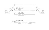
도 5는 기지 데이터 삽입에 따른 상기 데이터 인터리버의 입출력단에서 데이터 구성의 한 예를 보인다. 도 5의 (a)에서는 데이터 인터리버의 입력단에서 데이터 구성의 예를 보이고, 도 5의 (a)와 같이 데이터 인터리버에 입력될 때 그 출력의 구성을 도 5의 (b)에서 보인다.5 shows an example of a data configuration at an input / output terminal of the data interleaver according to known data insertion. FIG. 5A shows an example of the data configuration at the input terminal of the data interleaver, and the configuration of its output when input to the data interleaver as shown in FIG. 5A is shown in FIG. 5B.
즉, 수신기에서 데이터는 데이터 인터리버 출력단의 순서대로 수신되고, 시간적으로 연속적인 기지 데이터를 수신하기 위해서는 도 4의 번호 매김 순서에 상응하여 연속적으로 기지 데이터를 삽입하여야 한다. 도 5의 (b)의 예와 같이 수신기에서 수신하는 하나의 데이터 세그먼트가 모두 기지 데이터가 되기 위해서는 도 5의 (a)에서 같이 하나의 데이터 세그먼트를 52 바이트로 나누어 매 52 바이트 단위에서 같은 위치에 기지 데이터를 삽입하면 되고, 이때 기지 데이터 열의 시작 부분에서 초기화 바이트가 필요하다. 따라서 데이터 세그먼트 내 기지 데이터의 위치가 결정되면 데이터 인터리버 출력단에서 볼 때 일반 데이터가 끝나고 기지 데이터가 시작하는 위치가 초기화 바이트의 위치로 정해진다. 상기 기지 데이터와 초기화 바이트의 위치가 결정되면 비체계적 RS 패리티 바이트의 위치를 정할 수 있는데, 이는 데이터 인터리버 출력에서 볼 때 패리티 바이트들이 초기화 바이트들보다 뒤에 출력되도록 위치시키면 된다. 즉, 하나의 세그먼트에서 볼 때 도 4에서 표기한 번호가 작은 순서가 먼저 데이터 인터리버에서 출력되므로 초기화 바이트들의 순서 번호보다 나중 번호에 RS 패리티를 위치시키도록 하면 된다.That is, the data is received in the receiver in the order of the data interleaver output terminal, and in order to receive the known data continuously in time, the known data must be continuously inserted corresponding to the numbering sequence of FIG. 4. As in the example of FIG. 5 (b), in order for all of the data segments received by the receiver to be known data, one data segment is divided into 52 bytes as shown in FIG. This is done by inserting known data, which requires an initialization byte at the beginning of the known data sequence. Therefore, when the position of the known data in the data segment is determined, when the normal data ends and the known data starts from the data interleaver output terminal, the position of the known data is determined as the position of the initialization byte. Once the location of the known data and the initialization byte is determined, the location of the unstructured RS parity byte can be determined, which is to be positioned so that the parity bytes are output after the initialization bytes in the data interleaver output. That is, since the order in which the numbers indicated in FIG. 4 are smaller is output from the data interleaver first in one segment, RS parity may be located at a later number than the sequence number of initialization bytes.
상기 기지 데이터를 넣는 방법의 한 예로, 도 5의 (b)의 데이터 인터리버 후 단에서 볼 때 첫번째 세그먼트에서 MPEG 헤더 이후에 기지 데이터를 삽입하고 세그먼트 끝까지 기지 데이터가 오도록 한다면 두번째 세그먼트의 MPEG 헤더 바이트들은 인핸스드 데이터 패킷을 위한 정해진 값을 가지므로 상기 MPEG 헤더 바이트 역시 기지 데이터의 연속으로 사용할 수 있다.As an example of the method of inserting the known data, when the known data is inserted after the MPEG header in the first segment and the known data comes to the end of the segment, as seen from the data interleaver of FIG. The MPEG header byte can also be used as a sequence of known data because it has a fixed value for an enhanced data packet.
도 6a 내지 6c는 본 발명의 기지 데이터 삽입에 따른 인핸스드 데이터 패킷 그룹의 구성을 보여준다.6A to 6C show a configuration of an enhanced data packet group according to known data insertion of the present invention.
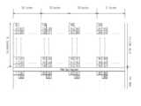
도 6a는 상기 데이터 인터리버(112 혹은 122) 입력단에서의 데이터 구성을 보이고, 도 6b는 상기 데이터 인터리버(112 혹은 122) 출력단에서의 데이터 구성을 보여주고 있다. 도 6c는 상기 데이터 인터리버의 출력 바이트들이 상기 트렐리스 부호화부(123) 내에서 바이트에서 심볼로 변환되고 심볼 영역에서 인터리빙되어 출력된 데이터 구성 결과이다.FIG. 6A shows the data configuration at the data interleaver 112 or 122 input terminal, and FIG. 6B shows the data configuration at the data interleaver 112 or 122 output terminal. FIG. 6C illustrates a data configuration result of output bytes of the data interleaver converted from bytes to symbols in the
도 6a에서 하나의 작은 네모는 하나의 바이트를 의미하고, 하나의 행(row)은 207 바이트로 구성된 하나의 인핸스드 데이터 패킷을 의미하며, 전체적으로 104개의 연속된 인핸스드 데이터 패킷이 하나의 그룹을 구성하는 것을 보여주고 있다. 상기 도면에서 녹색은 E-VSB 패킷 포맷터(102)에서 삽입된 0x47 동기 바이트를 제외한 3 바이트의 MPEG Transport 헤더 바이트를, 하늘색은 상기 E-VSB 패킷 포맷터(102)에서 삽입한 기지 데이터 위치 홀더 바이트를, 보라색은 RS 부호기/비체계적 RS 패리티 위치 홀더 삽입부(111 또는 121)에서 삽입한 비체계적 RS 패리티 위치 홀더 또는 패리티를, 노란색은 인핸스드 데이터를 그리고 빨간색은 트렐리스 부호기를 초기화하는데 사용될 기지 데이터 위치 홀더 바이트를 의미한다.한편 상기 도면에서 회색 영역과 주황색 영역은 모두 인핸스드 데이터를 의미하며, 회색 영역의 인핸스드 데이터는 인핸스드 데이터 패킷 그룹 이전의 메인 데이터와 상기 데이터 인터리버(112 혹은 122)에서 인터리빙되어 출력되고 주황색 영역의 인핸스드 데이터는 상기 인핸스드 데이터 그룹 이후의 메인 데이터와 상기 데이터 인터리버(112 혹은 122)에서 인터리빙되어 출력된다.In FIG. 6A, one small square means one byte, and one row means one enhanced data packet composed of 207 bytes, and in total, 104 consecutive enhanced data packets represent one group. It shows what constitutes it. In the figure, green denotes 3 bytes of MPEG Transport header bytes except 0x47 sync bytes inserted in the
도 6a의 인핸스드 데이터 패킷 그룹이 상기 데이터 인터리버(112 혹은 122)에 의하여 인터리빙되면 도 6b와 같이 출력된다. 도 6b에서 흰색 영역은 인핸스드 데이터 패킷 그룹 전후의 메인 데이터 바이트를 의미하고, 상기 도면에서는 인터리빙 결과 인핸스드 데이터 패킷 그룹의 바이트와 메인 데이터 바이트가 섞이는 것을 보여준다. 그리고 상기 도 6b를 보면 알 수 있듯이 본 실시예에 따른 인핸스드 데이터 패킷 그룹은 데이터 인터리버(112 혹은 122) 출력단에서 기지 데이터의 열(sequence)이 일정한 주기로 출력되는 특징을 가진다.If the enhanced data packet group of FIG. 6A is interleaved by the data interleaver 112 or 122, it is output as shown in FIG. 6B. In FIG. 6B, the white area means main data bytes before and after the enhanced data packet group, and in the figure, interleaving results show that the bytes of the enhanced data packet group are mixed with the main data bytes. As shown in FIG. 6B, the enhanced data packet group according to the present embodiment has a feature in which a sequence of known data is output at a constant period at an output terminal of the data interleaver 112 or 122.
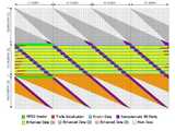
한편 도 6c는 상기 도 6b의 중간열인 52 패킷에 해당하는 영역이 트렐리스 부호화부(123)를 통해 바이트에서 심볼로 변환되고 부호화된 후 프레임 다중화기(140)를 거친 후의 데이터 출력을 보여주는 것으로, 심볼 영역에서의 데이터 구성을 나타내고 있다. 상기 도 6c에서 하나의 작은 네모는 하나의 심볼을 의미하고, 하나의 행은 4 개의 세그먼트 동기 심볼과 828(= 207 x 4)개의 데이터 심볼로 구성되는 하나의 데이터 세그먼트를 의미한다.FIG. 6C illustrates data output after passing through the
상기 데이터 인터리버(122)의 출력은 상기 트렐리스 부호화부(123)를 통해 바이트에서 심볼로 변환되고 심볼 영역에서 인터리빙 및 트렐리스 부호화되어 프레 임 다중화기(140)로 입력된다. 상기 프레임 다중화기(140)는 트렐리스 부호화되어 입력되는 828 심볼마다 4개의 세그먼트 동기 심볼을 부가하여 832개의 심볼을 가지는 데이터 세그먼트를 구성한다. 상기 도 6c에서 다홍색 영역은 프레임 다중화기(140)에서 삽입하는 세그먼트 동기 심볼을 의미한다.The output of the data interleaver 122 is converted from bytes to symbols through the
상기 도 6b에서 4 세그먼트마다 반복되는 각 기지 데이터 열 앞에 위치한 12 바이트의 빨간색 영역은 12 개의 트렐리스 부호기를 초기화하는데 사용될 바이트로써 상기 트렐리스 부호화부(123) 내에서 48개의 심볼로 변환되어 상기 도 6c와 같은 구성으로 된다. 그런데 각 트렐리스 부호기를 초기화하는데 2개의 심볼만 필요하고 총 12개의 트렐리스 부호기가 있으므로, 상기 48개의 빨간색 심볼 중에서 각 트렐리스 부호기마다 초기 두 심볼씩 총 24개의 심볼만이 트렐리스 초기화에 사용된다. 따라서 나머지 24 심볼은 기지 데이터 심볼로 사용될 수 있다.In FIG. 6B, the red region of 12 bytes located in front of each known data sequence repeated every 4 segments is converted into 48 symbols in the
한편 상기 도 6c에서 검은 테두리로 둘러싸인 영역은 동일한 기지 데이터 심볼열이 반복적으로 그리고 일정한 간격으로 삽입되는 영역이다. 여기서 기지 데이터 심볼열이 삽입되는 간격은 데이터 세그먼트 길이의 정수배인 것이 바람직하다. 이것은 상기 프레임 다중화기(140)에서 삽입되는 세그먼트 동기 심볼이 기지 데이터 열의 일부로 사용될 경우 일정한 위치에 삽입되도록 하기 위함이다.Meanwhile, in FIG. 6C, an area surrounded by a black border is an area in which the same known data symbol strings are repeatedly inserted at regular intervals. The interval at which the known data symbol strings are inserted is preferably an integer multiple of the data segment length. This is to ensure that the segment sync symbol inserted in the
상기 도 6a 내지 도 6c는 104개의 인핸스드 데이터 패킷이 하나의 그룹을 구성하는 실시 예이지만 하나의 그룹을 구성하는 인핸스드 패킷의 수는 임의의 개수로 할 수가 있다. 그러나 상기 데이터 인터리버(112 또는 122)가 52 패킷 단위로 데이터를 인터리빙하므로 이를 감안하여 52 패킷의 정수배로 하는 것이 바람직하 다.6A to 6C illustrate an embodiment in which 104 enhanced data packets form one group, but the number of enhanced packets constituting one group may be any number. However, since the data interleaver 112 or 122 interleaves data in units of 52 packets, it is preferable that the data interleaver 112 or 122 be an integer multiple of 52 packets.
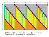
상기 도 6c에서는 기지 데이터 심볼열이 4 세그먼트 간격으로 반복적으로 삽입되는 경우를 보여주고 있다. 도 7a 내지 도 7c는 기지 데이터 심볼열이 5 세그먼트 간격으로 삽입되는 경우를 설명하고 있고, 도 8a 내지 도 8c는 8 세그먼트 간격으로 삽입되는 경우를 나타내고 있다.6C illustrates a case where the known data symbol string is repeatedly inserted at four segment intervals. 7A to 7C illustrate the case where known data symbol strings are inserted at five segment intervals, and FIGS. 8A to 8C illustrate the case where eight segment intervals are inserted.
이와 같이 본 발명에 따른 인핸스드 데이터 패킷은 정보가 실려서 전송되는 인핸스드 데이터와 수신기의 수신 성능 향상을 위해 삽입되는 기지 데이터를 포함하여 구성할 수 있다.As described above, the enhanced data packet according to the present invention may be configured to include enhanced data transmitted with information and known data inserted to improve reception performance of a receiver.
이때 상기 기지 데이터는 데이터 인터리버 후단의 출력 순서를 기준으로 연속적인 기지 데이터의 시작 부분에 트렐리스 부호기의 메모리 초기화 바이트가 필요하고, 데이터 세그먼트 내에 상기 초기화 바이트가 위치할 때 비체계적 RS 패리티 바이트들이 데이터 인터리버의 출력 순서상에서 상기 초기화 바이트보다 뒤에 출력될 수 있도록 위치해야 한다. 즉, 데이터 세그먼트 내에 초기화 바이트가 없다면 비체계적 RS 패리티 바이트의 위치는 어느 곳이나 상관없다. ㅇIn this case, the known data requires a memory initialization byte of the trellis encoder at the beginning of consecutive known data based on the output order of the data interleaver, and unstructured RS parity bytes are generated when the initialization byte is located in a data segment. The data interleaver should be positioned so that it can be output after the initialization byte. That is, if there is no initialization byte in the data segment, the location of the unstructured RS parity byte can be anywhere. ㅇ
이러한 기지 데이터와 트렐리스 부호기를 초기화하기 위한 기지 데이터 위치 홀더, 그리고 비체계적 RS 패리티 바이트의 위치 관계를 고려하여, E-VSB 패킷 포맷터(102)에서 기지 데이터 위치를 정하고 비체계적 RS 패리티 위치 홀더 삽입부(111 또는 121)에서 비체계적 RS 패리티 위치 홀더를 삽입하도록 인핸스드 데이터 패킷을 구성한다.In consideration of the positional relationship between the known data and the known data position holder for initializing the trellis encoder and the unstructured RS parity byte, the known data position is determined in the
도 9는 상기된 도 1과 같은 디지털 방송 송신 시스템에서 전송되는 데이터를 수신하여 복조 및 등화하여 원래 데이터로 복원하는 디지털 방송 수신 시스템의 일 실시예를 보인 구성 블록도이다.FIG. 9 is a block diagram illustrating an embodiment of a digital broadcast reception system for receiving, demodulating, and equalizing data transmitted from a digital broadcast transmission system as shown in FIG. 1 to restore original data.
도 9는 튜너(701), 복조부(702), 등화기(703), 기지 데이터 검출 및 발생부(704), 비터비 디코더(705), 데이터 디인터리버(706), RS 디코더 및 비체계적 RS 패리티 제거부(707), 디랜더마이저(708)를 포함하여 구성된다.9 shows
또한 상기 디지털 방송 수신 시스템은 메인 데이터 패킷 제거부(709), MPEG 헤더 제거부(710), E-VSB 패킷 디포맷터(711), 및 인핸스드 데이터 처리부(712)를 포함하여 구성된다.In addition, the digital broadcast receiving system includes a main
즉, 상기 튜너(701)는 특정 채널의 주파수를 튜닝하여 다운 컨버팅한 후 복조부(702)와 기지 데이터 검출 및 발생부(704)로 출력한다.That is, the
상기 복조부(702)는 튜닝된 채널 주파수에 대해 반송파 복구 및 타이밍 복구 등을 수행하여 기저대역 신호로 만든 후 등화기(703)와 기지 데이터 검출 및 발생부(704)로 출력한다.The
상기 등화기(703)는 상기 복조된 신호에 포함된 채널 상의 왜곡을 보상한 후 비터비 디코더(Viterbi decoder)(705)로 출력한다.The
이때 상기 기지 데이터 검출 및 발생부(704)는 상기 복조부(702)의 입/출력 데이터 즉, 복조가 이루어지기 전의 데이터 또는 복조가 이루어진 후의 데이터로부터 송신측에서 삽입한 기지 데이터 심볼열을 검출하고 발생시킨 기지 데이터의 심볼열을 복조부(702)와 등화기(703)로 출력한다.At this time, the known data detection and
상기 복조부(702)는 타이밍 복원이나 반송파 복구시에 상기 기지 데이터 심 볼열을 이용함으로써, 복조 성능을 향상시킬 수 있고, 등화기(703)에서도 마찬가지로 상기 기지 데이터를 사용하여 등화 성능을 향상시킬 수 있다.The
상기 비터비 디코더(705)는 상기 등화기(703)에서 출력되는 메인 데이터 심볼과 인핸스드 데이터 심볼에 대하여 비터비 복호를 수행하여 바이트로 변환한 후 이를 디인터리버(706)로 출력한다. 상기 디인터리버(706)는 송신측의 데이터 인터리버의 역과정을 수행하여 RS 복호기 및 비체계적 RS 패리티 제거기(RS encoder/Non-systematic RS parity remover)(707)로 출력한다. 상기 RS 복호기 및 비체계적 RS 패리티 제거기(707)에서는 입력받은 패킷이 메인 데이터 패킷인 경우 체계적 RS 복호를 수행하고, 인핸스드 데이터 패킷인 경우에는 패킷에 삽입되어 있는 비체계적 RS 패리티 바이트를 제거하여 디랜더마이저(708)로 출력한다.The
상기 디랜더마이저(708)는 RS 복호기 및 비체계적 RS 패리티 제거기(707)의 출력에 대하여 랜더마이저의 역과정을 수행하고 MPEG 동기 바이트를 매 패킷의 앞에 삽입하여 188 바이트 패킷 단위로 출력한다.The
상기 디랜더마이저(708)의 출력은 메인 MPEG 디코더(도시되지 않음)로 출력됨과 동시에 메인 데이터 패킷 제거부(709)로 출력된다. 상기 메인 MPEG 디코더는 메인 MPEG에 해당하는 패킷에 대해서만 디코딩을 수행한다. 이는 인핸스드 데이터 패킷이 기존 VSB 수신기에서 사용하지 않는 또는, 널 또는 예약된 PID를 가지기 때문에 메인 MPEG 디코더에서 디코딩에 사용되지 않고 무시되기 때문이다.The output of the
한편 상기 메인 데이터 패킷 제거부(709)는 디랜더마이저(708)의 출력으로부터 188바이트 단위의 메인 데이터 패킷을 제거하여 MPEG 헤더 제거부(710)로 출력한다. 상기 MPEG 헤더 제거부(710)는 송신측의 E-VSB 포맷터에서 인핸스드 데이터 패킷에 삽입했던 4바이트의 MPEG 헤더를 입력되는 인핸스드 데이터 패킷에서 제거하고 E-VSB 패킷 디포맷터(711)로 출력한다. 이때 상기 MPEG 헤더 제거부(710)는 E-VSB 패킷 디포맷터(711) 내에 구현될 수도 있다. 상기 E-VSB 패킷 디포맷터(711)는 상기 MPEG 헤더 제거부(710)에서 출력되는 184 바이트의 인핸스드 데이터 패킷에서 송신측에서 인핸스드 데이터가 아닌 위치 홀더가 삽입되었던 바이트들, 예를 들어 기지 데이터를 위한 위치 홀더들을 제거한 후 이를 E-VSB 데이터 처리부(712)로 출력한다. 상기 인핸스드 데이터 처리부(712)는 상기 E-VSB 패킷 디포맷터(711)의 출력에 대해 송신측의 E-VSB 전처리부(101)의 역과정을 수행하여 최종으로 인핸스드 데이터를 출력한다.Meanwhile, the main
한편, 본 발명에서 사용되는 용어(terminology)들은 본 발명에서의 기능을 고려하여 정의 내려진 용어들로써 이는 당분야에 종사하는 기술자의 의도 또는 관례 등에 따라 달라질 수 있으므로 그 정의는 본 발명의 전반에 걸친 내용을 토대로 내려져야 할 것이다.It is to be understood that the terminology used herein is for the purpose of description and should not be interpreted as limiting the scope of the present invention. .
본 발명은 상술한 실시예에 한정되지 않으며, 첨부된 청구범위에서 알 수 있는 바와 같이 본 발명이 속한 분야의 통상의 지식을 가지 자에 의해 변형이 가능하고 이러한 변형은 본 발명의 범위에 속한다.The present invention is not limited to the above-described embodiments, and can be modified by those skilled in the art as can be seen from the appended claims, and such modifications are within the scope of the present invention.
이상에서 설명한 바와 같은 본 발명에 따른 디지털 방송 시스템, 및 처리 방법은 채널을 통하여 부가 데이터를 송신할 때 오류에 강하고 또한 기존의 VSB 수신기와도 호환성이 가능한 이점이 있다. 더불어 기존의 VSB 시스템보다 고스트와 잡 음이 심한 채널에서도 부가 데이터를 오류없이 수신할 수 있는 이점이 있다.As described above, the digital broadcasting system and the processing method according to the present invention have an advantage of being resistant to errors and compatible with existing VSB receivers when transmitting additional data through a channel. In addition, there is an advantage that the additional data can be received without error even in a ghost and noisy channel than the conventional VSB system.
또한 본 발명은 데이터 영역의 특정 위치에 기지 데이터를 삽입하여 전송함으로써, 채널 변화가 심한 수신 시스템의 수신 성능을 향상시킬 수 있다.In addition, the present invention can improve the reception performance of a receiving system with a large channel change by inserting and transmitting known data in a specific position of the data area.
특히 본 발명은 기지 데이터를 포함하는 인핸스드 데이터 패킷에 대해 비체계적 RS 부호화를 수행함으로써, 패리티 위치를 이동할 수 있고, 이로 인해 연속적으로 긴 기지 데이터 열을 삽입할 수 있으면서, 삽입 위치에 대한 자유도를 높일 수 있다. 즉, 체계적 RS 부호화의 패리티 영역에 기지 데이터를 삽입할 수 있게 되고, 초기화 바이트가 올 수 있는 영역을 확대할 수 있다.In particular, the present invention can move the parity position by performing unsystematic RS coding on an enhanced data packet including known data, thereby inserting a long string of known data in succession, thereby improving the degree of freedom for the insertion position. It can increase. That is, the known data can be inserted into the parity region of the systematic RS encoding, and the region where the initialization byte can come can be enlarged.
이러한 본 발명은 채널 변화가 심하고 노이즈에 대한 강건성이 요구되는 휴대용 및 이동수신기에 적용하면 더욱 효과적이다.The present invention is more effective when applied to portable and mobile receivers that require severe channel changes and robustness against noise.
이상 설명한 내용을 통해 당업자라면 본 발명의 기술 사상을 일탈하지 아니하는 범위에서 다양한 변경 및 수정이 가능함을 알 수 있을 것이다.It will be apparent to those skilled in the art that various modifications and variations can be made in the present invention without departing from the spirit or scope of the invention.
따라서 본 발명의 기술적 범위는 실시예에 기재된 내용으로 한정되는 것이 아니라 특허 청구의 범위에 의하여 정해져야 한다.Therefore, the technical scope of the present invention should not be limited to the contents described in the embodiments but should be determined by the claims.
Claims (22)
Translated fromKoreanPriority Applications (13)
| Application Number | Priority Date | Filing Date | Title |
|---|---|---|---|
| KR1020050132489AKR101370889B1 (en) | 2005-12-28 | 2005-12-28 | Digital broadcasting system and processing method |
| US11/513,643US7940854B2 (en) | 2005-12-28 | 2006-08-30 | Digital television transmitter/receiver and method of processing data in digital television transmitter/receiver |
| CN2010102314113ACN101944964B (en) | 2005-10-17 | 2006-10-17 | Method for processing traffic information and digital broadcast system |
| CN2006101356019ACN1980138B (en) | 2005-10-17 | 2006-10-17 | Method for processing traffic information and digital broadcast transmitter |
| CN2006101669047ACN1992570B (en) | 2005-12-28 | 2006-12-11 | Digital broadcasting system and method of processing traffic information |
| CN2006101669032ACN1992569B (en) | 2005-12-28 | 2006-12-11 | Digital broadcasting system and method of processing traffic information |
| CN200610166754XACN1992567B (en) | 2005-12-28 | 2006-12-12 | Digital broadcasting system and method of processing traffic information |
| CN2006101667569ACN1992568B (en) | 2005-12-28 | 2006-12-12 | Digital broadcasting system and method of processing traffic information |
| CN2006101667554ACN101009525B (en) | 2005-12-28 | 2006-12-12 | Method of processing traffic information and digital broadcast system |
| CN2006101667535ACN1992566B (en) | 2005-12-28 | 2006-12-12 | Digital broadcasting system and method of processing traffic information |
| CN200610168450ACN100593340C (en) | 2005-12-28 | 2006-12-13 | Method for processing traffic information and digital broadcasting system |
| PCT/KR2006/005807WO2007075059A1 (en) | 2005-12-28 | 2006-12-28 | Digital broadcasting system and method of processing data |
| US13/075,115US8243849B2 (en) | 2005-12-28 | 2011-03-29 | Digital television transmitter/receiver and method of processing data in digital television transmitter/receiver |
Applications Claiming Priority (1)
| Application Number | Priority Date | Filing Date | Title |
|---|---|---|---|
| KR1020050132489AKR101370889B1 (en) | 2005-12-28 | 2005-12-28 | Digital broadcasting system and processing method |
Publications (2)
| Publication Number | Publication Date |
|---|---|
| KR20070069884A KR20070069884A (en) | 2007-07-03 |
| KR101370889B1true KR101370889B1 (en) | 2014-03-10 |
Family
ID=38193657
Family Applications (1)
| Application Number | Title | Priority Date | Filing Date |
|---|---|---|---|
| KR1020050132489AExpired - Fee RelatedKR101370889B1 (en) | 2005-10-17 | 2005-12-28 | Digital broadcasting system and processing method |
Country Status (3)
| Country | Link |
|---|---|
| US (2) | US7940854B2 (en) |
| KR (1) | KR101370889B1 (en) |
| CN (7) | CN1992570B (en) |
Families Citing this family (19)
| Publication number | Priority date | Publication date | Assignee | Title |
|---|---|---|---|---|
| WO2007091779A1 (en) | 2006-02-10 | 2007-08-16 | Lg Electronics Inc. | Digital broadcasting receiver and method of processing data |
| WO2007126196A1 (en) | 2006-04-29 | 2007-11-08 | Lg Electronics Inc. | Digital broadcasting system and method of processing data |
| WO2007136166A1 (en) | 2006-05-23 | 2007-11-29 | Lg Electronics Inc. | Digital broadcasting system and method of processing data |
| US7873104B2 (en) | 2006-10-12 | 2011-01-18 | Lg Electronics Inc. | Digital television transmitting system and receiving system and method of processing broadcasting data |
| KR101285887B1 (en) | 2007-03-26 | 2013-07-11 | 엘지전자 주식회사 | Digital broadcasting system and method of processing data in digital broadcasting system |
| KR101253185B1 (en) | 2007-03-26 | 2013-04-10 | 엘지전자 주식회사 | Digital broadcasting system and data processing method |
| KR101285888B1 (en)* | 2007-03-30 | 2013-07-11 | 엘지전자 주식회사 | Digital broadcasting system and method of processing data in digital broadcasting system |
| KR101490246B1 (en) | 2007-07-02 | 2015-02-05 | 엘지전자 주식회사 | Broadcast receiver and method of processing broadcast signal |
| US8433973B2 (en) | 2007-07-04 | 2013-04-30 | Lg Electronics Inc. | Digital broadcasting system and method of processing data |
| WO2009005326A2 (en) | 2007-07-04 | 2009-01-08 | Lg Electronics Inc. | Digital broadcasting system and method of processing data |
| KR101405975B1 (en) | 2007-07-23 | 2014-06-12 | 엘지전자 주식회사 | Digital broadcasting system and data processing method |
| KR20090012180A (en) | 2007-07-28 | 2009-02-02 | 엘지전자 주식회사 | Digital broadcasting system and data processing method |
| CN101836448A (en) | 2007-08-24 | 2010-09-15 | Lg电子株式会社 | Digital broadcasting system and method of processing data in digital broadcasting system |
| KR20090050994A (en)* | 2007-11-16 | 2009-05-20 | 엘지전자 주식회사 | Digital broadcasting system and data processing method |
| CN101540642B (en)* | 2008-03-20 | 2012-02-15 | 上海文广新闻传媒集团 | method of providing traffic service information in mobile multimedia broadcast |
| CN106601260B (en)* | 2016-11-30 | 2020-07-10 | 中山大学 | A virtual sound reproduction method for traffic noise maps |
| US10437928B2 (en)* | 2016-12-30 | 2019-10-08 | Google Llc | Device identifier dependent operation processing of packet based data communication |
| US10686557B2 (en)* | 2017-10-26 | 2020-06-16 | L3 Technologies Inc. | Enhanced decoding of coded sequences with structured data |
| CN111415521B (en)* | 2019-01-04 | 2022-08-02 | 阿里巴巴集团控股有限公司 | Method and device for selecting traffic information distribution road and electronic equipment |
Citations (4)
| Publication number | Priority date | Publication date | Assignee | Title |
|---|---|---|---|---|
| KR20050107287A (en)* | 2004-05-06 | 2005-11-11 | 삼성전자주식회사 | Digital broadcasting transmission/reception capable of improving receiving performance and signal processing method thereof |
| KR20050107286A (en)* | 2004-05-06 | 2005-11-11 | 삼성전자주식회사 | Digital broadcasting transmission/reception capable of improving receiving performance and signal processing method thereof |
| KR20050109052A (en)* | 2005-05-11 | 2005-11-17 | 삼성전자주식회사 | Digital broadcasting transmission/reception devices capable of improving a receiving performance and signal processing method thereof |
| KR20050111535A (en)* | 2005-05-18 | 2005-11-25 | 삼성전자주식회사 | Digital broadcasting transmission/reception devices capable of improving a receiving performance and signal processing method thereof |
Family Cites Families (22)
| Publication number | Priority date | Publication date | Assignee | Title |
|---|---|---|---|---|
| EP0899703B1 (en)* | 1997-08-25 | 2002-10-30 | Texas Instruments France | A navigational system |
| JP3389843B2 (en) | 1997-10-17 | 2003-03-24 | 日本電気株式会社 | Digital broadcast receiving system in information processing device |
| US6591292B1 (en)* | 1999-01-08 | 2003-07-08 | Thomson Licensing S.A. | Method and interface for incorporating program information into an electronic message |
| KR100360622B1 (en)* | 2000-06-12 | 2002-11-13 | 주식회사 문화방송 | MPEG Data frame structure and transmitting and receiving system using the same |
| US7111221B2 (en)* | 2001-04-02 | 2006-09-19 | Koninklijke Philips Electronics N.V. | Digital transmission system for an enhanced ATSC 8-VSB system |
| US7675994B2 (en)* | 2001-04-02 | 2010-03-09 | Koninklijke Philips Electronics N.V. | Packet identification mechanism at the transmitter and receiver for an enhanced ATSC 8-VSB system |
| US7206352B2 (en)* | 2001-04-02 | 2007-04-17 | Koninklijke Philips Electronics N.V. | ATSC digital television system |
| US20030099303A1 (en)* | 2001-06-04 | 2003-05-29 | Koninklijke Philips Electronics N.V. | Digital television (DTV) transmission system using enhanced coding schemes |
| KR100850932B1 (en)* | 2001-06-11 | 2008-08-12 | 엘지전자 주식회사 | Digital transmit system and method |
| KR100920738B1 (en)* | 2002-10-19 | 2009-10-07 | 삼성전자주식회사 | Transmission apparatus and method of digital broadcasting system with different error correction coding process according to communication environment |
| CN1505403A (en)* | 2002-12-02 | 2004-06-16 | 浙江大学 | Digital TV multi-service transmission method |
| US7564905B2 (en)* | 2002-12-20 | 2009-07-21 | Electronics And Telecommunications Research Institute | System and method for providing terrestrial digital broadcasting service using single frequency network |
| KR100585933B1 (en) | 2003-08-20 | 2006-06-01 | 한국전자통신연구원 | Digital Multimedia Broadcasting System and Method |
| KR100683179B1 (en)* | 2003-11-03 | 2007-02-15 | 삼성전자주식회사 | Robust Error Correction Coding / Decoding Apparatus and Method thereof for Dual Stream Digital Broadcast Transceiver |
| BRPI0506575A (en)* | 2004-01-27 | 2007-04-10 | Samsung Electronics Co Ltd | digital broadcast transmission / reception system having improved reception performance and signal processing method thereof |
| KR100744055B1 (en)* | 2004-06-23 | 2007-07-30 | 삼성전자주식회사 | Digital broadcasting transmission and reception system with improved reception performance and equalization performance and signal processing method thereof |
| CN1635558A (en)* | 2004-12-30 | 2005-07-06 | 武汉汉网高技术有限公司 | Digital video broadcast or digital audio broadcast based traffic information distribution method |
| CN100414572C (en)* | 2005-01-11 | 2008-08-27 | 肖禄生 | Road state information real-time publishing and applying system in city |
| US7920602B2 (en)* | 2005-05-23 | 2011-04-05 | Samsung Electronics Co., Ltd. | Method for formatting digital broadcast transport stream packet for improved receiving performance, digital broadcast transmitter, and signal processing method thereof |
| KR101191181B1 (en)* | 2005-09-27 | 2012-10-15 | 엘지전자 주식회사 | Transmitting/receiving system of digital broadcasting and data structure |
| KR100797176B1 (en)* | 2005-10-21 | 2008-01-23 | 삼성전자주식회사 | Digital broadcasting system and method |
| US7797607B2 (en)* | 2005-12-27 | 2010-09-14 | Lg Electronics, Inc. | DTV transmitter and method of coding main and enhanced data in DTV transmitter |
- 2005
- 2005-12-28KRKR1020050132489Apatent/KR101370889B1/ennot_activeExpired - Fee Related
- 2006
- 2006-08-30USUS11/513,643patent/US7940854B2/ennot_activeExpired - Fee Related
- 2006-12-11CNCN2006101669047Apatent/CN1992570B/ennot_activeExpired - Fee Related
- 2006-12-11CNCN2006101669032Apatent/CN1992569B/ennot_activeExpired - Fee Related
- 2006-12-12CNCN2006101667554Apatent/CN101009525B/ennot_activeExpired - Fee Related
- 2006-12-12CNCN200610166754XApatent/CN1992567B/ennot_activeExpired - Fee Related
- 2006-12-12CNCN2006101667535Apatent/CN1992566B/ennot_activeExpired - Fee Related
- 2006-12-12CNCN2006101667569Apatent/CN1992568B/ennot_activeExpired - Fee Related
- 2006-12-13CNCN200610168450Apatent/CN100593340C/ennot_activeExpired - Fee Related
- 2011
- 2011-03-29USUS13/075,115patent/US8243849B2/ennot_activeExpired - Fee Related
Patent Citations (4)
| Publication number | Priority date | Publication date | Assignee | Title |
|---|---|---|---|---|
| KR20050107287A (en)* | 2004-05-06 | 2005-11-11 | 삼성전자주식회사 | Digital broadcasting transmission/reception capable of improving receiving performance and signal processing method thereof |
| KR20050107286A (en)* | 2004-05-06 | 2005-11-11 | 삼성전자주식회사 | Digital broadcasting transmission/reception capable of improving receiving performance and signal processing method thereof |
| KR20050109052A (en)* | 2005-05-11 | 2005-11-17 | 삼성전자주식회사 | Digital broadcasting transmission/reception devices capable of improving a receiving performance and signal processing method thereof |
| KR20050111535A (en)* | 2005-05-18 | 2005-11-25 | 삼성전자주식회사 | Digital broadcasting transmission/reception devices capable of improving a receiving performance and signal processing method thereof |
Also Published As
| Publication number | Publication date |
|---|---|
| CN101009525A (en) | 2007-08-01 |
| CN1992568B (en) | 2012-07-04 |
| US8243849B2 (en) | 2012-08-14 |
| CN1992905A (en) | 2007-07-04 |
| CN1992566B (en) | 2012-10-10 |
| CN1992570B (en) | 2011-05-11 |
| KR20070069884A (en) | 2007-07-03 |
| CN1992567A (en) | 2007-07-04 |
| CN101009525B (en) | 2012-01-25 |
| US7940854B2 (en) | 2011-05-10 |
| CN100593340C (en) | 2010-03-03 |
| US20070147432A1 (en) | 2007-06-28 |
| CN1992567B (en) | 2013-01-16 |
| US20110179334A1 (en) | 2011-07-21 |
| CN1992566A (en) | 2007-07-04 |
| CN1992570A (en) | 2007-07-04 |
| CN1992569A (en) | 2007-07-04 |
| CN1992568A (en) | 2007-07-04 |
| CN1992569B (en) | 2012-07-18 |
Similar Documents
| Publication | Publication Date | Title |
|---|---|---|
| KR101191182B1 (en) | Digital broadcasting system and processing method | |
| KR101208504B1 (en) | Digital broadcasting system and processing method | |
| KR101191181B1 (en) | Transmitting/receiving system of digital broadcasting and data structure | |
| US8243849B2 (en) | Digital television transmitter/receiver and method of processing data in digital television transmitter/receiver | |
| US8379759B2 (en) | Digital broadcasting system and method of processing data | |
| KR101253187B1 (en) | Digital broadcasting system and method of processing data in digital broadcasting system | |
| KR101216079B1 (en) | Digital broadcasting system and processing method | |
| KR101208509B1 (en) | Digital broadcasting system and processing method | |
| US8176375B2 (en) | DTV transmitter and method of coding data in DTV transmitter | |
| KR101199373B1 (en) | Digital broadcasting system and processing method | |
| KR101199372B1 (en) | Digital broadcasting system and processing method | |
| KR101215363B1 (en) | Digital broadcasting system and processing method | |
| KR101265629B1 (en) | Digital broadcasting system and data processing method | |
| KR100925448B1 (en) | Broadcast transmitter / receiver and broadcast signal processing method | |
| KR101191191B1 (en) | Digital broadcasting system and processing method | |
| KR101215364B1 (en) | Digital broadcasting system and processing method | |
| KR100917203B1 (en) | Digital Broadcasting System and Processing Method | |
| KR101162213B1 (en) | Digital broadcasting system and processing method | |
| KR100917210B1 (en) | Digital broadcasting system and data processing method | |
| KR20070089509A (en) | Digital Broadcasting System and Processing Method |
Legal Events
| Date | Code | Title | Description |
|---|---|---|---|
| PA0109 | Patent application | St.27 status event code:A-0-1-A10-A12-nap-PA0109 | |
| P11-X000 | Amendment of application requested | St.27 status event code:A-2-2-P10-P11-nap-X000 | |
| P13-X000 | Application amended | St.27 status event code:A-2-2-P10-P13-nap-X000 | |
| PG1501 | Laying open of application | St.27 status event code:A-1-1-Q10-Q12-nap-PG1501 | |
| PN2301 | Change of applicant | St.27 status event code:A-3-3-R10-R13-asn-PN2301 St.27 status event code:A-3-3-R10-R11-asn-PN2301 | |
| R18-X000 | Changes to party contact information recorded | St.27 status event code:A-3-3-R10-R18-oth-X000 | |
| R18-X000 | Changes to party contact information recorded | St.27 status event code:A-3-3-R10-R18-oth-X000 | |
| A201 | Request for examination | ||
| P11-X000 | Amendment of application requested | St.27 status event code:A-2-2-P10-P11-nap-X000 | |
| P13-X000 | Application amended | St.27 status event code:A-2-2-P10-P13-nap-X000 | |
| PA0201 | Request for examination | St.27 status event code:A-1-2-D10-D11-exm-PA0201 | |
| D13-X000 | Search requested | St.27 status event code:A-1-2-D10-D13-srh-X000 | |
| D14-X000 | Search report completed | St.27 status event code:A-1-2-D10-D14-srh-X000 | |
| E902 | Notification of reason for refusal | ||
| PE0902 | Notice of grounds for rejection | St.27 status event code:A-1-2-D10-D21-exm-PE0902 | |
| P11-X000 | Amendment of application requested | St.27 status event code:A-2-2-P10-P11-nap-X000 | |
| P13-X000 | Application amended | St.27 status event code:A-2-2-P10-P13-nap-X000 | |
| R17-X000 | Change to representative recorded | St.27 status event code:A-3-3-R10-R17-oth-X000 | |
| E902 | Notification of reason for refusal | ||
| PE0902 | Notice of grounds for rejection | St.27 status event code:A-1-2-D10-D21-exm-PE0902 | |
| P11-X000 | Amendment of application requested | St.27 status event code:A-2-2-P10-P11-nap-X000 | |
| P13-X000 | Application amended | St.27 status event code:A-2-2-P10-P13-nap-X000 | |
| E701 | Decision to grant or registration of patent right | ||
| PE0701 | Decision of registration | St.27 status event code:A-1-2-D10-D22-exm-PE0701 | |
| GRNT | Written decision to grant | ||
| PR0701 | Registration of establishment | St.27 status event code:A-2-4-F10-F11-exm-PR0701 | |
| PR1002 | Payment of registration fee | St.27 status event code:A-2-2-U10-U11-oth-PR1002 Fee payment year number:1 | |
| PG1601 | Publication of registration | St.27 status event code:A-4-4-Q10-Q13-nap-PG1601 | |
| PN2301 | Change of applicant | St.27 status event code:A-5-5-R10-R13-asn-PN2301 St.27 status event code:A-5-5-R10-R11-asn-PN2301 | |
| LAPS | Lapse due to unpaid annual fee | ||
| PC1903 | Unpaid annual fee | St.27 status event code:A-4-4-U10-U13-oth-PC1903 Not in force date:20170301 Payment event data comment text:Termination Category : DEFAULT_OF_REGISTRATION_FEE | |
| PC1903 | Unpaid annual fee | St.27 status event code:N-4-6-H10-H13-oth-PC1903 Ip right cessation event data comment text:Termination Category : DEFAULT_OF_REGISTRATION_FEE Not in force date:20170301 | |
| PN2301 | Change of applicant | St.27 status event code:A-5-5-R10-R13-asn-PN2301 St.27 status event code:A-5-5-R10-R11-asn-PN2301 |