KR101370843B1 - Device for discharging heat - Google Patents
Device for discharging heatDownload PDFInfo
- Publication number
- KR101370843B1 KR101370843B1KR1020090123678AKR20090123678AKR101370843B1KR 101370843 B1KR101370843 B1KR 101370843B1KR 1020090123678 AKR1020090123678 AKR 1020090123678AKR 20090123678 AKR20090123678 AKR 20090123678AKR 101370843 B1KR101370843 B1KR 101370843B1
- Authority
- KR
- South Korea
- Prior art keywords
- refrigerant
- circulation pipe
- heat
- chamber portion
- chamber
- Prior art date
- Legal status (The legal status is an assumption and is not a legal conclusion. Google has not performed a legal analysis and makes no representation as to the accuracy of the status listed.)
- Active
Links
Images


Classifications
- H—ELECTRICITY
- H05—ELECTRIC TECHNIQUES NOT OTHERWISE PROVIDED FOR
- H05K—PRINTED CIRCUITS; CASINGS OR CONSTRUCTIONAL DETAILS OF ELECTRIC APPARATUS; MANUFACTURE OF ASSEMBLAGES OF ELECTRICAL COMPONENTS
- H05K7/00—Constructional details common to different types of electric apparatus
- H05K7/20—Modifications to facilitate cooling, ventilating, or heating
- H05K7/20218—Modifications to facilitate cooling, ventilating, or heating using a liquid coolant without phase change in electronic enclosures
- H05K7/20272—Accessories for moving fluid, for expanding fluid, for connecting fluid conduits, for distributing fluid, for removing gas or for preventing leakage, e.g. pumps, tanks or manifolds
- G—PHYSICS
- G06—COMPUTING OR CALCULATING; COUNTING
- G06F—ELECTRIC DIGITAL DATA PROCESSING
- G06F1/00—Details not covered by groups G06F3/00 - G06F13/00 and G06F21/00
- G06F1/16—Constructional details or arrangements
- G06F1/20—Cooling means
Landscapes
- Engineering & Computer Science (AREA)
- Microelectronics & Electronic Packaging (AREA)
- Physics & Mathematics (AREA)
- Thermal Sciences (AREA)
- Cooling Or The Like Of Electrical Apparatus (AREA)
Abstract
Translated fromKorean
Description
Translated fromKorean본 발명은 방열장치에 관한 것으로서, 보다 상세하게는 열 부하 장치로부터 발생되는 열을 효과적으로 방출할 수 있는 방열장치에 관한 것이다.The present invention relates to a heat dissipation device, and more particularly, to a heat dissipation device capable of effectively dissipating heat generated from a heat load device.
기술이 발전함에 따라 고성능을 발휘하는 각종 전자장치, 예를 들어 연산 속도가 매우 빠른 컴퓨터 및 해상도가 매우 높은 평판 디스플레이 등이 개발되고 있다. 이러한 전자장치는 고성능으로 말미암아 작동시 필연적으로 열이 많이 발생한다.As technology develops, various electronic devices that exhibit high performance, for example, computers with extremely high computing speed and flat panel displays with very high resolution are being developed. Such electronic devices are inevitably heat generated due to their high performance.
이러한 열의 발생은 고성능 전자장치에 내장된 고발열부품에 주로 기인한다. 고발열부품으로는 중앙처리장치(CPU), 그래픽 모듈(Graphic Processing Unit) 또는 구동 회로 모듈 등이 있으며, 고발열부품은 주로 인쇄회로기판에 실장되거나 인쇄회로기판 상의 슬롯 등의 연결부와 연결되어 전원을 인가받는다.The generation of this heat is mainly due to the high heat generation component embedded in the high performance electronics. The high-temperature components include a central processing unit (CPU), a graphic module (Graphic Processing Unit), or a driving circuit module. The high-temperature component is mainly mounted on a printed circuit board or connected to a connection portion such as a slot on a printed circuit board Receive.
그런데, 각종 고발열부품에서 발생되는 열은 외부로 효과적으로 방출되어야 한다. 왜냐하면 발생열이 효과적으로 방출되지 않으면 발열부품의 성능 저하 또는 고장 등이 발생하여 고성능 전자장치의 안정적인 작동 및 충분한 수명을 보장할 수 없게 되며 이는 궁극적으로 고성능 전자장치의 상업화를 불가능하게 하기 때문이 다.However, heat generated from various high-temperature parts must be effectively discharged to the outside. If the generated heat is not effectively released, the performance of the heat-generating components may be degraded or failures may occur, and thus stable operation and sufficient lifespan of the high-performance electronic devices may not be guaranteed, which ultimately makes commercialization of the high-performance electronic devices impossible.
이러한 이유에서 종래에는 발생열을 방출하기 위한 방열장치로서, 히트싱크 및 팬을 이용하여 공기를 순환시키는 구조가 채택되었다. 이러한 구조를 통해서, 발열부품이 내장된 공간의 공기 및 외부 공기가 상호 열교환됨으로써 발열부품의 열은 외부로 방출된다.For this reason, conventionally, a structure for circulating air using a heat sink and a fan has been adopted as a heat dissipating device for discharging generated heat. Through this structure, the heat of the heat generating component is discharged to the outside by mutual heat exchange between the air and the outside air in the space in which the heat generating component is embedded.
그러나, 종래의 방열장치는 방열 효율을 높이는데 뚜렷한 한계가 있었으며, 이로 인해 각종 고성능 전자장치의 발열문제를 근본적으로 해결하지 못하였다. 또한, 공기의 순환 과정에서 먼지나 각종 이물질이 전자장치 내부로 유입되어 발열부품의 오작동을 초래하는 원인이 되고 있다. 그리고, 발열부품이 산소와 항상 접촉하고 있어서 쉽게 산화되어 오작동이 발생되는 문제점도 있다. 더구나 이러한 공기 순환식 구조는 복잡하여 냉각 효율을 충분히 확보하기 어려운 문제가 있었다.However, the conventional heat dissipating device has a significant limitation in improving the heat dissipation efficiency, and thus it has not fundamentally solved the heat generation problem of various high performance electronic devices. In addition, dust and various foreign substances flow into the electronic device during the air circulation process, causing malfunction of the heat generating parts. Further, there is also a problem that the heat generating component always comes in contact with oxygen and is easily oxidized to cause malfunction. Moreover, such an air circulation structure has a problem in that it is difficult to secure sufficiently cooling efficiency.
이와 같이 종래의 공기 순환식 방열장치는 그 구조적인 한계로 말미암아 냉각 효율을 충분히 높일 수가 없었다. 냉각효율의 저하는 열손실을 유발하며 공기에 포함된 먼지 등의 각종 오염물질은 히트싱크의 방열핀 등에 침착되어 점진적인 냉각 효율의 저하를 초래하게 되므로, 결국 제품의 수명이 크게 단축되는 문제가 있었다.As described above, the conventional air circulation type heat dissipation device cannot sufficiently increase the cooling efficiency due to its structural limitations. The decrease in cooling efficiency causes heat loss and various contaminants such as dust contained in the air are deposited on the heat sink fins of the heat sink, resulting in a gradual decrease in cooling efficiency, resulting in a significant shortening of the life of the product.
한편, 공기 순환식 방열장치에 대한 대안으로서 냉매가 봉입된 히트 파이프를 이용하는 방열구조가 고안된 바 있다. 그러나, 히트 파이프를 이용한 방열구조는 중력에 의한 대류 현상을 이용하도록 구성되어 있어서, 설치 방법에 따라 방열 성능이 크게 좌우될 뿐만 아니라 수동적이어서 총 열전달량에 상당한 제약이 있다 는 한계가 있었다. 따라서, 히트 싱크의 열전도 보조재료로서만 사용되고 있는 실정이다.On the other hand, a heat dissipation structure using a heat pipe with a refrigerant has been devised as an alternative to the air circulation heat dissipation device. However, since the heat dissipation structure using the heat pipe is configured to use the convection phenomenon due to gravity, the heat dissipation performance is largely dependent on the installation method, and it is passive, and thus there is a limit to the total heat transfer amount. Therefore, it is used only as a heat conduction auxiliary material of a heat sink.
본 발명은 상기한 문제점을 해결하기 위해서 안출된 것으로서, 본 발명의 목적은, 열 부하 장치로부터 발생되는 열을 능동적으로 배출할 수 있을 뿐만 아니라 방열 효율이 크게 향상된 방열장치를 제공하는 것이다.SUMMARY OF THE INVENTION The present invention has been made to solve the above problems, and an object of the present invention is to provide a heat dissipation device capable of actively dissipating heat generated from a heat load device as well as greatly improving heat dissipation efficiency.
상기 목적을 달성하기 위해, 본 발명에 따른 방열장치는 열 부하장치로부터 발생되는 열을 방출하기 위한 방열장치에 있어서, 냉매가 내부에서 유동 가능하도록 중공 형상으로 이루어지며, 상기 냉매가 상기 열 부하장치와 열교환을 하도록 상기 열 부하장치와 연결되며, 상기 냉매가 순환하도록 상기 열 부하장치와 폐회로를 구성하는 순환파이프; 상기 순환파이프에 결합되어 상기 냉매가 유입 및 유출되며, 상기 유입되는 냉매가 압력이 증가하여 배출되도록 상기 냉매를 가압하는 가압유닛; 및 상기 가압유닛에 의해 가압된 냉매가 상기 열 부하장치로 공급될 때에 상기 냉매ㅊ의 압력을 감소시키는 감압유닛;을 구비하는 것을 특징으로 한다.In order to achieve the above object, the heat dissipation device according to the present invention is a heat dissipation device for dissipating heat generated from the heat load device, the refrigerant is made of a hollow shape so as to flow inside, the refrigerant is the heat load device A circulation pipe connected to the heat load device to exchange heat with and configured to form a closed circuit with the heat load device to circulate the refrigerant; A pressurizing unit coupled to the circulation pipe and pressurizing the refrigerant so that the refrigerant flows in and out, and the refrigerant flows in and out of the refrigerant; And a decompression unit for reducing the pressure of the refrigerant when the refrigerant pressurized by the pressing unit is supplied to the heat load device.
본 발명에 따르면, 냉매가 가압 및 감압을 거치면서 순환하게 되므로, 냉매가 열 부하장치와 효과적으로 열 교환하게 된다. 따라서, 종래의 방열장치에 비해 방열 효율을 크게 개선할 수 있으며, 나아가 고발열성의 열 부하장치의 발열 문제도 근본적으로 해결할 수 있게 되어 고성능 전자장치의 상업화도 가능하게 된다.According to the present invention, since the refrigerant is circulated through pressure and pressure reduction, the refrigerant is effectively heat exchanged with the heat load device. Therefore, the heat dissipation efficiency can be greatly improved as compared with the conventional heat dissipation device. Furthermore, the heat dissipation problem of the high heat dissipation device can be fundamentally solved, thereby enabling the commercialization of high-performance electronic devices.
또한, 전류를 제어하면 코일 주위에 발생되는 자기장을 변화시킬 수 있게 되 므로, 플런저의 직선 이동을 제어할 수 있게 된다. 이와 같이 플런저의 직선 이동이 제어되면, 제1챔버부로부터 제2챔버부로 유동하는 냉매의 부피를 조절할 수 있으며 나아가 제2챔버부로부터 순환파이프로 유출되는 냉매의 부피 및 압력을 조절할 수 있게 되므로, 열 부하장치의 열을 능동적으로 방출할 수 있게 된다.In addition, by controlling the current, it is possible to change the magnetic field generated around the coil, thereby controlling the linear movement of the plunger. As such, when the linear movement of the plunger is controlled, the volume of the refrigerant flowing from the first chamber portion to the second chamber portion can be adjusted, and further, the volume and pressure of the refrigerant flowing out of the circulation pipe from the second chamber portion can be adjusted. The heat of the heat load device can be actively released.
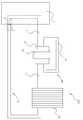
도 1은 본 발명의 일 실시예에 따른 방열장치의 개략적인 구성도이고, 도 2는 도 1에 도시된 가압유닛의 구조를 설명하기 위한 개략적인 단면도이며, 도 3 및 도 4는 도 2에 도시된 가압유닛에 의한 냉매의 가압을 설명하기 위한 도면들이며, 도 5는 도 1에 표시된 원형의 점선으로 도시된 부분의 개략적인 확대도이다.1 is a schematic configuration diagram of a heat dissipation device according to an embodiment of the present invention, Figure 2 is a schematic cross-sectional view for explaining the structure of the pressure unit shown in Figure 1, Figures 3 and 4 Figures are for explaining the pressurization of the refrigerant by the pressurization unit shown, Figure 5 is a schematic enlarged view of a portion shown by the circular dotted line shown in FIG.
도 1 내지 도 5를 참조하면, 본 실시예의 방열장치(100)는 열 부하 장치(1), 예를 들어 고성능의 컴퓨터, 자동차 엔진 및 반도체 장비 등으로부터 작동 과정에서 발생되는 열을 효과적으로 방출하기 위한 것이다. 따라서, 열 부하 장치(1)는 열을 방출하는 것이면 그 종류나 형태에 관계가 없다.1 to 5, the
방열장치(100)는 순환파이프(10)와, 가압유닛(20)과, 감압유닛과, 히트싱크(40)를 구비한다.The
순환파이프(10)는 중공의 파이프 형상으로 이루어진다. 순환파이프(10)는 열 부하장치(1)와 폐회로를 구성한다. 따라서, 순환파이프(10)의 내부를 유동하는 냉매, 예를 들어 물이나 알코올 등은 순환파이프(10) 및 열 부하장치(1)를 계속해서 순환할 수 있게 되며, 이에 따라 냉매는 열 부하장치(1)와 열교환을 하여 열 부하장치로부터 열을 흡수한 후에 열 부하장치로 다시 유입되기 전에 흡수한 열을 외 부로 방출한다. 여기서, 순환파이프(10)는 후술하는 다른 구성요소에 의해 복수의 순환파이프요소(11)를 포함하도록 구성된다. 또한, 열 부하장치(1)에는 순환파이프요소(11)가 삽입될 수도 있으며, 경우에 따라서는 열 부하장치(1)에 냉매가 순환하는 유로(미도시)가 형성되며, 유로가 순환파이프(10)와 연결되도록 구성될 수도 있다. 다만, 본 실시예에서는 열 부하장치(1)에 순환파이프요소(11)가 삽입되는 것을 예로 들어 설명하기로 한다.The
가압유닛(20)은 순환파이프(10)에 결합된다. 가압유닛(20)은 순환하는 냉매를 가압하여 압력이 증가된 상태로 배출하는 기능을 수행한다. 가압유닛(20)은 하우징(21)과, 보조순환파이프(22)와, 코일(23)과, 플런저(24)와, 제1유입밸브(25)와, 제2유입밸브(26)와, 제1유출밸브(27)와, 제2유출밸브(28)를 구비한다.The pressurizing
하우징(21)은 전체적으로 박스 형상으로 이루어진다. 하우징(21)에는 챔버(211)와, 제1연통로(212)와, 제2연통로(213)와, 제1보조연통로(214)와, 제2보조연통로(215)가 형성된다.The
챔버(211)는 순환파이프(10)와 서로 연통된다. 따라서, 순환파이프(10)를 유동하는 냉매는 챔버(21)로 유입된 후에, 챔버(21)로부터 유출된다. 그리고, 챔버(21)는 플런저(24)에 의해 제1챔버부(211a) 및 제2챔버부(211b)로 구분된다. 제1챔버부(211a)는 챔버의 내측벽과 플런저의 일측에 의해 형성되는 공간으로서, 순환파이프(10)로부터 유입되는 냉매가 저장된다. 제2챔버부(211b)는 챔버의 내측벽과 플런저의 타측에 의해 형성되는 공간이며, 제2챔버부(211b)에 저장된 냉매는 후술하는 플런저(24)의 작동에 의해 가압되어 압력이 증가한 상태로 순환파이프(10) 로 배출된다.The chamber 211 is in communication with the
제1연통로(212)는 제1챔버부(211a) 및 순환파이프(10)를 상호 연결시키는 연통로이며, 하우징(21)의 일측면으로 개방된다. 따라서, 순환파이프(10)를 유동하는 냉매는 제1연통로(212)를 거쳐 제1챔버부(211a)로 유입된다. 그리고, 제1연통로(212)에는 시트부(212a)가 형성되며, 도 2에 도시된 상태에서 제1연통로(212)의 직경은 시트부(212a)를 중심으로 좌측부분이 우측부분보다 더 작다.The
제2연통로(213)는 제2챔버부(211b) 및 순환파이프(10)를 상호 연결시키는 연통로이며, 하우징(21)의 타측면으로 개방된다. 따라서, 제2챔버부(211b)의 냉매는 제2연통로(213)를 거쳐 순환파이프(10)로 유출된다. 그리고, 제2연통로(213)에는 시트부(213a)가 형성되며, 도 2에 도시된 상태에서 제2연통로(213)의 직경은 시트부(213a)를 중심으로 좌측부분이 우측부분보다 더 작다.The
제1보조연통로(214) 및 제2보조연통로(215)는 각각 제1챔버부(211a) 및 제2챔버부(211b)와 연결된다. 제1보조연통로(214) 및 제2보조연통로(215)는 하우징(21)의 일측면 및 타측면으로 각각 개방되게 형성된다. 그리고, 제1보조연통로(214) 및 제2보조연통로(215)에는 각각 시트부(214a,215a)가 형성되며, 도 2에 도시된 상태에서 제1보조연통로(214)의 직경 및 제2보조연통로(215)의 직경은 각각 시트부(214a,215a)를 중심으로 좌측부분이 우측부분보다 더 크다.The first
보조순환파이프(22)는 중공의 파이프 형상으로 이루어진다. 보조순환파이프(22)의 양단부는 각각 제1보조연통로(214) 및 제2보조연통로(215)와 연통된다.The
코일(23)은 환형을 이루며, 하우징(21)의 외측면에 결합된다. 코일(23)에는 전류가 인가되며, 이에 따라 코일 주위에는 자기장이 형성된다. 그리고, 코일(23)에 인가되는 전류의 세기나 방향이 변화하면, 자기장의 세기나 방향도 변화한다.The
플런저(24)는 하우징의 챔버(211) 내부에 배치되며, 이에 따라 챔버(211)는 앞서 설명한 바와 같이 제1챔버부(211a)와 제2챔버부(211b)로 구분된다. 플런저(24)는 자성을 가지는 자성부재(241) 및 자성부재를 감싸는 커버부재(242)를 포함한다. 자성부재(241)는 영구자석으로 구성되는 것이 바람직하다.The plunger 24 is disposed inside the chamber 211 of the housing, whereby the chamber 211 is divided into a
그리고, 플런저(24)는 자성부재(241)를 포함하도록 구성되므로, 코일(23)에 의해 형성되는 자기장이 변화하게 되면, 플런저(24)는 하우징에 대해 상대 이동하게 된다. 즉, 플런저(24)는 도 2에 도시된 상태에서 자기장의 변화에 따라 도 3에 도시되어 있는 바와 같이 좌측으로 직선 이동할 수도 있으며, 도 4에 도시되어 있는 바와 같이 우측으로 직선 이동할 수도 있다. 왜냐하면, 코일(23) 주위의 자기장과 플런저의 자성부재(241)의 자기력이 상호 작용하기 때문이다. 이와 같이 플런저(24)가 직선 이동하게 되면, 플런저(24)의 위치에 따라 제1챔버부(211a) 및 제2챔버부(211b)의 크기가 변하게 된다.In addition, since the plunger 24 is configured to include the
제1유입밸브(25), 제2유입밸브(26), 제1유출밸브(27) 및 제2유출밸브(28)는 모두 냉매의 일방향으로의 흐름은 허용하고 일방향의 반대방향으로의 흐름은 차단하는 원웨이밸브(one-way valve)로 구성된다.The
제1유입밸브(25)는 제1연통로(212)의 내부에 설치되는 볼 형태의 밸브체(25)로 구성된다. 순환파이프(10)의 냉매가 제1챔버부(21a)로 유입될 때에는, 냉매의 유입 압력에 의해 밸브체(25)가 제1연통로의 시트부(212a)로부터 이격된다. 그리 고, 후술하는 바와 같이 플런저(24)가 도 2에 도시된 상태에서 도 3에 도시된 상태로 이동하면, 그 이동 과정에서 제1챔버부(211a)의 냉매는 플런저(24)에 의해 가압되므로, 밸브체(25)는 제1연통로의 시트부(212a)를 폐쇄한다. 따라서, 순환파이프(10) 내부의 냉매는 제1챔버부(211a)로 유입될 수 있을 뿐 역류하는 것은 방지된다.The
제2유입밸브(26)는 제2보조연통로(215)의 내부에 설치되는 볼 형태의 밸브체(26)로 구성된다. 후술하는 바와 같이 제1챔버부(211a)의 냉매가 플런저(24)에 의해 가압되어 보조순환파이프(22)로 배출되면, 밸브체(26)는 제2보조연통로의 시트부(215a)로부터 이격되므로, 보조순환파이프(22) 내부의 냉매는 제2챔버부(211b)로 유입된다. 한편, 제2챔버부(211a)의 냉매가 플런저(24)에 의해 가압되어 순환파이프(10)로 배출되면, 밸브체(26)가 제2보조연통로의 시트부(215a)를 폐쇄하므로 냉매가 보소순환파이프(22)로 유출되는 것이 방지된다.The
제1유출밸브(27)는 제1보조연통로(214)의 내부에 설치되는 볼 형태의 밸브체(27)로 구성된다. 후술하는 바와 같이 플런저(24)가 도 2에 도시된 상태에서 도 3에 도시된 상태로 이동하면, 그 이동 과정에서 제1챔버부(211a)의 냉매는 플런저(24)에 의해 가압되어 밸브체(27)가 제1보조연통로의 시트부(214a)를 개방하므로, 제1챔버부(211a)의 냉매는 보조순환파이프(22)로 배출된다. 그리고, 제1챔버부(211a)의 압력이 제1보조연통로(214) 중 밸브체 좌측 부분의 압력보다 작은 경우가 발생하더라도, 밸브체(27)가 제1보조연통로의 시트부(214a)를 폐쇄하므로 냉매의 유입은 차단된다.The
제2유출밸브(28)는 제2연통로(213)의 내부에 설치되는 볼 형태의 밸브체(28)로 구성된다. 후술하는 바와 같이 플런저(24)가 도 2 또는 도 3에 도시된 상태에서 도 4에 도시된 상태로 이동하면, 그 이동 과정에서 제2챔버부(211b)의 냉매는 플런저에 의해 가압되어 밸브체(28)가 제2연통로의 시트부(213a)로부터 이격되므로, 냉매가 제2연통로(213)를 통해 순환파이프(10)로 배출된다. 그리고, 제2챔버부(211b)의 압력이 제2연통로(212) 중 밸브체(28) 우측 부분의 압력보다 작은 경우가 발생하더라도, 밸브체(28)가 제2연통로의 시트부(213a)를 폐쇄하므로 냉매의 유입은 차단된다.The
이와 같이 플런저(24)가 도 2에 도시된 상태에서 좌우 수평방향으로 직선 이동하게 되면, 제1챔버부(211a)의 냉매는 플런저(24)에 의해 가압되어 보조순환파이프(22)를 통해 제2챔버부(211b)로 유입된다. 이 때, 제1챔버부(211a)의 냉매가 제1연통로(212)를 통해 유출되는 것은 제1유입밸브(25)에 의해 방지된다. 또한, 제2챔버부(211b)의 냉매는 플런저의 의해 다시 가압되어 순환파이프(10)로 배출된다. 이 때, 제2챔버부의 냉매가 제2보조연통로(215)를 통해 유출되는 것은 제2유출밸브(28)에 의해 방지된다. 이와 같이, 가압유닛(20)으로부터 배출되는 냉매의 압력은 가압유닛에 유입되기 전에 비해 압력이 증가하게 된다.As such, when the plunger 24 is linearly moved in the horizontal direction in the left and right directions in the state shown in FIG. 2, the refrigerant of the
한편, 플런저(24)의 직선 이동에 의한 냉매의 가압시에, 제1챔버부(211a)의 냉매가 플런저의 커버부재(242) 및 챔버(211)의 내측면 사이의 틈을 통해 유동하는 것을 최대한 방지하는 것이 바람직하다. 이를 위해서, 커버부재(242)와 챔버의 내측면 사이는 미세한 갭(gap)이 형성되는 것이 바람직하다. 또한, 냉매의 누설을 방지하며 플런저(24)의 부드러운 이동을 보장하기 위해서 커버부재(242)와 챔버(211)의 내측면 사이에는 오일 등의 윤활제가 도포되는 것이 바람직하다.On the other hand, when the refrigerant is pressurized by the linear movement of the plunger 24, the refrigerant of the
감압유닛은 가압유닛(20)에 의해 가압된 냉매가 열 부하장치(1)로 공급될 때에 냉매의 압력을 감소시킨다. 본 실시예에서 감압유닛은 감압노즐(31)로 구성된다.The pressure reducing unit reduces the pressure of the refrigerant when the refrigerant pressurized by the
감압노즐(31)은 열 부하장치(1)의 근처, 즉 도 1에 참조부호 A로 지시된 부분에 순환파이프(10)와 연결되도록 결합될 수도 있으나, 본 실시예에서는 참조부호 B로 지시된 부분, 즉 열 부하장치(1)의 내부에 배치된다. 또한, 본 실시예에서는 감압노즐(31)이 순환파이프(10)와 별개의 구성요소로 구성되어 있으나, 감압노즐(31)은 순환파이프(10)와 한 몸체를 형성하도록 구성될 수도 있다.The
감압노즐(31)은 노즐부(311) 및 한 쌍의 확장부(312)를 포함한다.The
노즐부(311)는 중공 형상이며, 노즐부(311)의 직경은 길이에 무관하게 일정하다.The
한 쌍의 확장부(312)는 각각 노즐부(311)의 양단부에 연결된다. 각 확장부(312)는 노즐부(311)의 단부로부터 멀어질수록 직경이 점진적으로 증가하는 부분(312a) 및 직경이 일정한 부분(312b)을 포함한다.The pair of
이와 같이 감압노즐(31)이 형성되면, 열 부하장치(1)로 공급되는 냉매는 감압노즐의 노즐부(311)를 통과할 때에 속력이 크게 증가하게 되어 자연스럽게 압력이 떨어지게 된다. 이와 같이 냉매의 압력이 떨어지면, 냉매가 열 부하장치(1)로부터 발생되는 열을 보다 효과적으로 흡수하여 기화가 쉽게 이루어지게 된다. 따 라서, 열 부하장치의 열이 효과적으로 배출된다.When the
히트싱크(40)는 다수의 방열핀을 포함하는 것으로서, 열 부하장치(1)로부터 열을 얻은 냉매를 순환시키면서 열을 외부로 방출하는 역할을 한다. 히트싱크(40)는 하우징(21)과 열 부하장치(1) 사이에 배치되며, 공랭식이나 수냉식 등으로 구성될 수 있으며, 이러한 히트싱크의 구조는 널리 알려져 있으므로 이에 대한 상세한 설명은 생략하기로 한다.The
상술한 바와 같이 본 발명에 따른 방열장치(100)에 있어서는, 열 부하장치(1)로부터 열을 얻은 냉매가 가압유닛(20)에 의해 가압되어 압력이 증가하는 1차 과정 그리고 열 부하장치(1)의 내부로 유입되는 냉매가 유입 직전 또는 직후에 감압노즐의 노즐부(311)를 통과하면서 압력이 떨어지는 2차 과정이 발생하게 된다. 이와 같이 냉매가 가압 및 감압을 거치면서 순환하게 되므로, 냉매가 열 부하장치(1)와 효과적으로 열 교환하게 된다. 따라서, 종래의 방열장치에 비해 방열 효율을 크게 개선할 수 있으며, 나아가 고발열성의 열 부하장치의 발열 문제도 근본적으로 해결할 수 있게 되어 고성능 전자장치의 상업화도 가능하게 된다.In the
또한, 전류를 제어하면 코일(23) 주위에 발생되는 자기장을 변화시킬 수 있게 되므로, 플런저(24)의 직선 이동을 제어할 수 있게 된다. 이와 같이 플런저(24)의 직선 이동이 제어되면, 제1챔버부(211a)로부터 제2챔버부(211b)로 유동하는 냉매의 부피를 조절할 수 있으며 나아가 제2챔버부(211b)로부터 순환파이프(10)로 유출되는 냉매의 부피 및 압력을 조절할 수 있게 된다. 이와 같이 순환파이프(10)로 유출되는 냉매의 부피 및 압력이 조절되면, 열 부하장치(1)의 발열문제를 보다 능동적으로 해결할 수 있게 된다. 예를 들어, 열 부하장치로부터 발생되는 열이 증가하면, 전류를 제어하여 플런저의 직선 이동 주기를 증가시킴으로써 냉매를 보다 빠른 주기로 가압하여 공급할 수 있다. 그리고, 열 부하장치로부터 발생되는 열이 감소하면, 플런저의 직선 이동 주기를 감소시킴으로써 냉매의 공급량을 효과적으로 줄이거나 냉매의 가압 정도를 낮출 수 있다.In addition, by controlling the current, the magnetic field generated around the
한편, 가압유닛은 다양한 형태로 구성될 수 있으며, 그 변형예가 도 6에 도시되어 있다.On the other hand, the pressurizing unit may be configured in various forms, a modification thereof is shown in FIG.
도 6을 참조하면, 본 실시예의 가압유닛(200)에 있어서 플런저(240)는 자성부재(243)와 격벽부재(244)를 포함한다.Referring to FIG. 6, in the pressurizing unit 200 of the present embodiment, the plunger 240 includes a
자성부재(243)는 자성을 가지는 것으로서, 예를 들어 영구자석으로 구성된다.The
격벽부재(244)는 탄성변형 가능한 소재, 예를 들어 고무 등으로 이루어진다. 격벽부재(244)는 하우징(21)의 내부에 배치되되, 격벽부재(244)의 양단부는 각각 하우징(21)에 삽입되어 고정된다. 그리고, 하우징의 챔버(211)는 격벽부재(244)에 의해 제1챔버부(211a) 및 제2챔버부(211b)로 구별되며, 제1챔버부(211a) 및 제2챔버부(211b)는 서로 격리된다. 격벽부재(244), 바람직하게는 격벽부재의 중앙에는 자성부재(243)가 고정된다.The partition member 244 is made of an elastically deformable material, for example, rubber. The partition member 244 is disposed inside the
이와 같이 구성된 가압유닛(240)에 있어서, 코일(23)에 인가되는 전류가 변하게 되면, 자성부재(243)가 좌측 또는 우측방향으로 직선 이동하게 되므로, 결국 격벽부재(244)가 도 6에 가상선으로 도시되어 있는 바와 같이 좌측으로 볼록하거나 우측으로 볼록한 모양으로 탄성변형을 하게 된다. 이와 같이 격벽부재(244)가 탄성변형을 하면, 제1챔버부(211a)의 냉매를 제2챔버부(211b)로 유동시킬 수 있거나 제2챔버부(211b)의 냉매를 가압하여 순환파이프(10)로 배출할 수 있게 된다.In the pressurizing unit 240 configured as described above, when the current applied to the
이상, 본 발명을 바람직한 실시예들을 들어 상세하게 설명하였으나, 본 발명은 상기 실시예들에 한정되지 않으며, 본 발명의 기술적 사상 내에서 당 분야에서 통상의 지식을 가진 자에 의하여 여러 가지 많은 변형이 가능함은 명백하다.While the present invention has been particularly shown and described with reference to exemplary embodiments thereof, it is to be understood that the invention is not limited to the disclosed exemplary embodiments. Various changes and modifications may be made by those skilled in the art within the technical scope of the present invention. The possibilities are obvious.
예를 들어, 본 실시예에서는 제1유입밸브, 제2유입밸브, 제1유출밸브 및 제2유출밸브가 모두 구비되도록 구성되어 있으나, 경우에 따라서는 제1유출밸브 및 제2유출밸브가 구비되지 않도록 구성할 수도 있다.For example, in the present embodiment, the first inlet valve, the second inlet valve, the first outlet valve, and the second outlet valve are configured to be provided, but in some cases, the first outlet valve and the second outlet valve are provided. It can also be configured not to.
도 1은 본 발명의 일 실시예에 따른 방열장치의 개략적인 구성도이다.1 is a schematic configuration diagram of a heat radiation device according to an embodiment of the present invention.
도 2는 도 1에 도시된 가압유닛의 구조를 설명하기 위한 개략적인 단면도이다.Figure 2 is a schematic cross-sectional view for explaining the structure of the pressing unit shown in FIG.
도 3 및 도 4는 도 2에 도시된 가압유닛에 의한 냉매의 가압을 설명하기 위한 도면들이다.3 and 4 are views for explaining the pressurization of the refrigerant by the pressure unit shown in FIG.
도 5는 도 1에 표시된 원형의 점선으로 도시된 부분의 개략적인 확대도이다.FIG. 5 is a schematic enlarged view of a portion shown by the dotted dotted line shown in FIG.
도 6은 본 발명의 다른 실시예에 따른 가압유닛의 개략적인 단면도이다.6 is a schematic cross-sectional view of a pressing unit according to another embodiment of the present invention.
<도면의 주요부분에 대한 부호의 설명>Description of the Related Art
1...열 부하장치 10...순환파이프1 ...
20...가압유닛 21...하우징20 ...
22...보조순환파이프 23...코일22 ...
24,240...플런저 25...제1유입밸브24,240 ...
26...제2유입밸브 27...제1유출밸브26 ...
28...제2유출밸브 31...감압노즐28.2
40...히트싱크 100...방열장치40
211...챔버 212,213...연통로211 Chamber 212,213
212a,213a,214a,215a...시트부 214,215...보조연통로212a, 213a, 214a, 215a ... Secondary sections 214,215 ...
241,243...자성부재 242...커버부재241,243 ...
244...격벽부재 311...노즐부244
312...확장부312.Extension
Claims (8)
Translated fromKoreanPriority Applications (1)
| Application Number | Priority Date | Filing Date | Title |
|---|---|---|---|
| KR1020090123678AKR101370843B1 (en) | 2009-12-14 | 2009-12-14 | Device for discharging heat |
Applications Claiming Priority (1)
| Application Number | Priority Date | Filing Date | Title |
|---|---|---|---|
| KR1020090123678AKR101370843B1 (en) | 2009-12-14 | 2009-12-14 | Device for discharging heat |
Publications (2)
| Publication Number | Publication Date |
|---|---|
| KR20110067189A KR20110067189A (en) | 2011-06-22 |
| KR101370843B1true KR101370843B1 (en) | 2014-03-25 |
Family
ID=44399680
Family Applications (1)
| Application Number | Title | Priority Date | Filing Date |
|---|---|---|---|
| KR1020090123678AActiveKR101370843B1 (en) | 2009-12-14 | 2009-12-14 | Device for discharging heat |
Country Status (1)
| Country | Link |
|---|---|
| KR (1) | KR101370843B1 (en) |
Cited By (22)
| Publication number | Priority date | Publication date | Assignee | Title |
|---|---|---|---|---|
| US10012448B2 (en) | 2012-09-27 | 2018-07-03 | X Development Llc | Systems and methods for energy storage and retrieval |
| US20180187595A1 (en)* | 2016-12-30 | 2018-07-05 | X Development Llc | Variable Pressure Turbine |
| US10082104B2 (en) | 2016-12-30 | 2018-09-25 | X Development Llc | Atmospheric storage and transfer of thermal energy |
| US10082045B2 (en) | 2016-12-28 | 2018-09-25 | X Development Llc | Use of regenerator in thermodynamic cycle system |
| US10094219B2 (en) | 2010-03-04 | 2018-10-09 | X Development Llc | Adiabatic salt energy storage |
| US10221775B2 (en) | 2016-12-29 | 2019-03-05 | Malta Inc. | Use of external air for closed cycle inventory control |
| US10233787B2 (en) | 2016-12-28 | 2019-03-19 | Malta Inc. | Storage of excess heat in cold side of heat engine |
| US10233833B2 (en) | 2016-12-28 | 2019-03-19 | Malta Inc. | Pump control of closed cycle power generation system |
| US10280804B2 (en) | 2016-12-29 | 2019-05-07 | Malta Inc. | Thermocline arrays |
| US10436109B2 (en) | 2016-12-31 | 2019-10-08 | Malta Inc. | Modular thermal storage |
| US10458284B2 (en) | 2016-12-28 | 2019-10-29 | Malta Inc. | Variable pressure inventory control of closed cycle system with a high pressure tank and an intermediate pressure tank |
| US11053847B2 (en) | 2016-12-28 | 2021-07-06 | Malta Inc. | Baffled thermoclines in thermodynamic cycle systems |
| US11286804B2 (en) | 2020-08-12 | 2022-03-29 | Malta Inc. | Pumped heat energy storage system with charge cycle thermal integration |
| US11396826B2 (en) | 2020-08-12 | 2022-07-26 | Malta Inc. | Pumped heat energy storage system with electric heating integration |
| US11454167B1 (en) | 2020-08-12 | 2022-09-27 | Malta Inc. | Pumped heat energy storage system with hot-side thermal integration |
| US11480067B2 (en) | 2020-08-12 | 2022-10-25 | Malta Inc. | Pumped heat energy storage system with generation cycle thermal integration |
| US11486305B2 (en) | 2020-08-12 | 2022-11-01 | Malta Inc. | Pumped heat energy storage system with load following |
| US11678615B2 (en) | 2018-01-11 | 2023-06-20 | Lancium Llc | Method and system for dynamic power delivery to a flexible growcenter using unutilized energy sources |
| US11852043B2 (en) | 2019-11-16 | 2023-12-26 | Malta Inc. | Pumped heat electric storage system with recirculation |
| US11982228B2 (en) | 2020-08-12 | 2024-05-14 | Malta Inc. | Pumped heat energy storage system with steam cycle |
| US12123327B2 (en) | 2020-08-12 | 2024-10-22 | Malta Inc. | Pumped heat energy storage system with modular turbomachinery |
| US12428979B2 (en) | 2021-12-14 | 2025-09-30 | Malta Inc. | Pumped heat energy storage system integrated with coal-fired energy generation unit |
Families Citing this family (1)
| Publication number | Priority date | Publication date | Assignee | Title |
|---|---|---|---|---|
| TWI749400B (en)* | 2019-11-18 | 2021-12-11 | 致茂電子股份有限公司 | Electronic load device and heat-dissipating load module |
Citations (2)
| Publication number | Priority date | Publication date | Assignee | Title |
|---|---|---|---|---|
| KR200315458Y1 (en)* | 2003-03-17 | 2003-06-02 | 창 쉬-외이 | Heat dissipation device with liquid coolant |
| JP2008038804A (en) | 2006-08-08 | 2008-02-21 | Nippo Ltd | Pump and cooling system using the pump |
- 2009
- 2009-12-14KRKR1020090123678Apatent/KR101370843B1/enactiveActive
Patent Citations (2)
| Publication number | Priority date | Publication date | Assignee | Title |
|---|---|---|---|---|
| KR200315458Y1 (en)* | 2003-03-17 | 2003-06-02 | 창 쉬-외이 | Heat dissipation device with liquid coolant |
| JP2008038804A (en) | 2006-08-08 | 2008-02-21 | Nippo Ltd | Pump and cooling system using the pump |
Cited By (59)
| Publication number | Priority date | Publication date | Assignee | Title |
|---|---|---|---|---|
| US10094219B2 (en) | 2010-03-04 | 2018-10-09 | X Development Llc | Adiabatic salt energy storage |
| US11761336B2 (en) | 2010-03-04 | 2023-09-19 | Malta Inc. | Adiabatic salt energy storage |
| US10907513B2 (en) | 2010-03-04 | 2021-02-02 | Malta Inc. | Adiabatic salt energy storage |
| US11156385B2 (en) | 2012-09-27 | 2021-10-26 | Malta Inc. | Pumped thermal storage cycles with working fluid management |
| US10012448B2 (en) | 2012-09-27 | 2018-07-03 | X Development Llc | Systems and methods for energy storage and retrieval |
| US10428693B2 (en) | 2012-09-27 | 2019-10-01 | Malta Inc. | Pumped thermal systems with dedicated compressor/turbine pairs |
| US11754319B2 (en) | 2012-09-27 | 2023-09-12 | Malta Inc. | Pumped thermal storage cycles with turbomachine speed control |
| US10458283B2 (en) | 2012-09-27 | 2019-10-29 | Malta Inc. | Varying compression ratios in energy storage and retrieval systems |
| US10458721B2 (en) | 2012-09-27 | 2019-10-29 | Malta Inc. | Pumped thermal storage cycles with recuperation |
| US10443452B2 (en) | 2012-09-27 | 2019-10-15 | Malta Inc. | Methods of hot and cold side charging in thermal energy storage systems |
| US10288357B2 (en) | 2012-09-27 | 2019-05-14 | Malta Inc. | Hybrid pumped thermal systems |
| US10422250B2 (en) | 2012-09-27 | 2019-09-24 | Malta Inc. | Pumped thermal systems with variable stator pressure ratio control |
| US10428694B2 (en) | 2012-09-27 | 2019-10-01 | Malta Inc. | Pumped thermal and energy storage system units with pumped thermal system and energy storage system subunits |
| US11053847B2 (en) | 2016-12-28 | 2021-07-06 | Malta Inc. | Baffled thermoclines in thermodynamic cycle systems |
| US12012902B2 (en) | 2016-12-28 | 2024-06-18 | Malta Inc. | Variable pressure inventory control of closed cycle system with a high pressure tank and an intermediate pressure tank |
| US11512613B2 (en) | 2016-12-28 | 2022-11-29 | Malta Inc. | Storage of excess heat in cold side of heat engine |
| US10233833B2 (en) | 2016-12-28 | 2019-03-19 | Malta Inc. | Pump control of closed cycle power generation system |
| US10458284B2 (en) | 2016-12-28 | 2019-10-29 | Malta Inc. | Variable pressure inventory control of closed cycle system with a high pressure tank and an intermediate pressure tank |
| US10233787B2 (en) | 2016-12-28 | 2019-03-19 | Malta Inc. | Storage of excess heat in cold side of heat engine |
| US11454168B2 (en) | 2016-12-28 | 2022-09-27 | Malta Inc. | Pump control of closed cycle power generation system |
| US11927130B2 (en) | 2016-12-28 | 2024-03-12 | Malta Inc. | Pump control of closed cycle power generation system |
| US11591956B2 (en) | 2016-12-28 | 2023-02-28 | Malta Inc. | Baffled thermoclines in thermodynamic generation cycle systems |
| US11371442B2 (en) | 2016-12-28 | 2022-06-28 | Malta Inc. | Variable pressure inventory control of closed cycle system with a high pressure tank and an intermediate pressure tank |
| US10907510B2 (en) | 2016-12-28 | 2021-02-02 | Malta Inc. | Storage of excess heat in cold side of heat engine |
| US12129791B2 (en) | 2016-12-28 | 2024-10-29 | Malta Inc. | Baffled thermoclines in thermodynamic cycle systems |
| US10920674B2 (en) | 2016-12-28 | 2021-02-16 | Malta Inc. | Variable pressure inventory control of closed cycle system with a high pressure tank and an intermediate pressure tank |
| US10920667B2 (en) | 2016-12-28 | 2021-02-16 | Malta Inc. | Pump control of closed cycle power generation system |
| US10082045B2 (en) | 2016-12-28 | 2018-09-25 | X Development Llc | Use of regenerator in thermodynamic cycle system |
| US10221775B2 (en) | 2016-12-29 | 2019-03-05 | Malta Inc. | Use of external air for closed cycle inventory control |
| US10907548B2 (en) | 2016-12-29 | 2021-02-02 | Malta Inc. | Use of external air for closed cycle inventory control |
| US11578622B2 (en) | 2016-12-29 | 2023-02-14 | Malta Inc. | Use of external air for closed cycle inventory control |
| US10280804B2 (en) | 2016-12-29 | 2019-05-07 | Malta Inc. | Thermocline arrays |
| US10082104B2 (en) | 2016-12-30 | 2018-09-25 | X Development Llc | Atmospheric storage and transfer of thermal energy |
| US11352951B2 (en) | 2016-12-30 | 2022-06-07 | Malta Inc. | Variable pressure turbine |
| WO2018125550A1 (en)* | 2016-12-30 | 2018-07-05 | X Development Llc | Variable pressure turbine |
| US10801404B2 (en) | 2016-12-30 | 2020-10-13 | Malta Inc. | Variable pressure turbine |
| AU2017387803B2 (en)* | 2016-12-30 | 2020-08-13 | Malta Inc. | Variable pressure turbine |
| US20180187595A1 (en)* | 2016-12-30 | 2018-07-05 | X Development Llc | Variable Pressure Turbine |
| US10830134B2 (en) | 2016-12-31 | 2020-11-10 | Malta Inc. | Modular thermal storage |
| US10436109B2 (en) | 2016-12-31 | 2019-10-08 | Malta Inc. | Modular thermal storage |
| US11655759B2 (en) | 2016-12-31 | 2023-05-23 | Malta, Inc. | Modular thermal storage |
| US11678615B2 (en) | 2018-01-11 | 2023-06-20 | Lancium Llc | Method and system for dynamic power delivery to a flexible growcenter using unutilized energy sources |
| US11852043B2 (en) | 2019-11-16 | 2023-12-26 | Malta Inc. | Pumped heat electric storage system with recirculation |
| US11578650B2 (en) | 2020-08-12 | 2023-02-14 | Malta Inc. | Pumped heat energy storage system with hot-side thermal integration |
| US11486305B2 (en) | 2020-08-12 | 2022-11-01 | Malta Inc. | Pumped heat energy storage system with load following |
| US11840932B1 (en) | 2020-08-12 | 2023-12-12 | Malta Inc. | Pumped heat energy storage system with generation cycle thermal integration |
| US11846197B2 (en) | 2020-08-12 | 2023-12-19 | Malta Inc. | Pumped heat energy storage system with charge cycle thermal integration |
| US11480067B2 (en) | 2020-08-12 | 2022-10-25 | Malta Inc. | Pumped heat energy storage system with generation cycle thermal integration |
| US11885244B2 (en) | 2020-08-12 | 2024-01-30 | Malta Inc. | Pumped heat energy storage system with electric heating integration |
| US11454167B1 (en) | 2020-08-12 | 2022-09-27 | Malta Inc. | Pumped heat energy storage system with hot-side thermal integration |
| US11982228B2 (en) | 2020-08-12 | 2024-05-14 | Malta Inc. | Pumped heat energy storage system with steam cycle |
| US11396826B2 (en) | 2020-08-12 | 2022-07-26 | Malta Inc. | Pumped heat energy storage system with electric heating integration |
| US12123327B2 (en) | 2020-08-12 | 2024-10-22 | Malta Inc. | Pumped heat energy storage system with modular turbomachinery |
| US12123347B2 (en) | 2020-08-12 | 2024-10-22 | Malta Inc. | Pumped heat energy storage system with load following |
| US11286804B2 (en) | 2020-08-12 | 2022-03-29 | Malta Inc. | Pumped heat energy storage system with charge cycle thermal integration |
| US12173643B2 (en) | 2020-08-12 | 2024-12-24 | Malta Inc. | Pumped heat energy storage system with hot-side thermal integration |
| US12173648B2 (en) | 2020-08-12 | 2024-12-24 | Malta Inc. | Pumped heat energy storage system with thermal plant integration |
| US12428989B2 (en) | 2020-08-12 | 2025-09-30 | Malta Inc. | Pumped heat energy storage system with load following |
| US12428979B2 (en) | 2021-12-14 | 2025-09-30 | Malta Inc. | Pumped heat energy storage system integrated with coal-fired energy generation unit |
Also Published As
| Publication number | Publication date |
|---|---|
| KR20110067189A (en) | 2011-06-22 |
Similar Documents
| Publication | Publication Date | Title |
|---|---|---|
| KR101370843B1 (en) | Device for discharging heat | |
| CN114303037B (en) | Re-entry fluid cold plate | |
| TWI419641B (en) | Cooling structure of electronic device | |
| JP5644767B2 (en) | Heat transport structure of electronic equipment | |
| US20130056178A1 (en) | Ebullient cooling device | |
| CN100499089C (en) | Radiator | |
| US7885074B2 (en) | Direct jet impingement-assisted thermosyphon cooling apparatus and method | |
| US8385066B2 (en) | Flow control device and cooled electronic system employing the same | |
| US7284389B2 (en) | Two-fluid spray cooling system | |
| CN104487794B (en) | Cooling device, electric vehicle and electronic equipment equipped with the cooling device | |
| WO2010084717A1 (en) | Cooling device | |
| KR19980019402A (en) | CPU COOLING DEVICE OF PC | |
| JP5252204B2 (en) | Cooling system | |
| EP4633304A1 (en) | Electronic device | |
| US9706681B2 (en) | Modular electronic system | |
| CN103703335B (en) | Cooling device, electronic equipment equipped with the same, and electric vehicle | |
| JP6825615B2 (en) | Cooling system and cooler and cooling method | |
| WO2018061814A1 (en) | Power supply device | |
| US20080308257A1 (en) | Heat dissipating assembly | |
| KR101172679B1 (en) | Outdoor unit of air conditioner | |
| JP2018105525A (en) | Cooling device, electronic apparatus mounted with the same and electric vehicle | |
| CN218675393U (en) | Printer ray apparatus module with high heat dissipation performance | |
| JP3006557B2 (en) | Cooling device for electronic equipment or electronic components | |
| JP5682951B2 (en) | Semiconductor package cooling system | |
| US20070062675A1 (en) | Heat dissipating system |
Legal Events
| Date | Code | Title | Description |
|---|---|---|---|
| PA0109 | Patent application | Patent event code:PA01091R01D Comment text:Patent Application Patent event date:20091214 | |
| PG1501 | Laying open of application | ||
| A201 | Request for examination | ||
| PA0201 | Request for examination | Patent event code:PA02012R01D Patent event date:20120417 Comment text:Request for Examination of Application Patent event code:PA02011R01I Patent event date:20091214 Comment text:Patent Application | |
| E902 | Notification of reason for refusal | ||
| PE0902 | Notice of grounds for rejection | Comment text:Notification of reason for refusal Patent event date:20130730 Patent event code:PE09021S01D | |
| E701 | Decision to grant or registration of patent right | ||
| PE0701 | Decision of registration | Patent event code:PE07011S01D Comment text:Decision to Grant Registration Patent event date:20131230 | |
| GRNT | Written decision to grant | ||
| PR0701 | Registration of establishment | Comment text:Registration of Establishment Patent event date:20140228 Patent event code:PR07011E01D | |
| PR1002 | Payment of registration fee | Payment date:20140228 End annual number:3 Start annual number:1 | |
| PG1601 | Publication of registration | ||
| FPAY | Annual fee payment | Payment date:20170203 Year of fee payment:4 | |
| PR1001 | Payment of annual fee | Payment date:20170203 Start annual number:4 End annual number:4 | |
| FPAY | Annual fee payment | Payment date:20190201 Year of fee payment:6 | |
| PR1001 | Payment of annual fee | Payment date:20190201 Start annual number:6 End annual number:6 | |
| PR1001 | Payment of annual fee | Payment date:20210208 Start annual number:8 End annual number:8 | |
| PR1001 | Payment of annual fee | Payment date:20220208 Start annual number:9 End annual number:9 | |
| PR1001 | Payment of annual fee | Payment date:20230302 Start annual number:10 End annual number:10 |