KR101369840B1 - Remote control system for excabator - Google Patents
Remote control system for excabatorDownload PDFInfo
- Publication number
- KR101369840B1 KR101369840B1KR1020110144528AKR20110144528AKR101369840B1KR 101369840 B1KR101369840 B1KR 101369840B1KR 1020110144528 AKR1020110144528 AKR 1020110144528AKR 20110144528 AKR20110144528 AKR 20110144528AKR 101369840 B1KR101369840 B1KR 101369840B1
- Authority
- KR
- South Korea
- Prior art keywords
- excavator
- bucket
- driving
- arm
- joystick
- Prior art date
- Legal status (The legal status is an assumption and is not a legal conclusion. Google has not performed a legal analysis and makes no representation as to the accuracy of the status listed.)
- Active
Links
Images


Classifications
- E—FIXED CONSTRUCTIONS
- E02—HYDRAULIC ENGINEERING; FOUNDATIONS; SOIL SHIFTING
- E02F—DREDGING; SOIL-SHIFTING
- E02F9/00—Component parts of dredgers or soil-shifting machines, not restricted to one of the kinds covered by groups E02F3/00 - E02F7/00
- E02F9/20—Drives; Control devices
- E02F9/2004—Control mechanisms, e.g. control levers
- E02F9/2008—Control mechanisms in the form of the machine in the reduced scale model
- B—PERFORMING OPERATIONS; TRANSPORTING
- B62—LAND VEHICLES FOR TRAVELLING OTHERWISE THAN ON RAILS
- B62D—MOTOR VEHICLES; TRAILERS
- B62D5/00—Power-assisted or power-driven steering
- B62D5/06—Power-assisted or power-driven steering fluid, i.e. using a pressurised fluid for most or all the force required for steering a vehicle
- B62D5/09—Power-assisted or power-driven steering fluid, i.e. using a pressurised fluid for most or all the force required for steering a vehicle characterised by means for actuating valves
- B62D5/093—Telemotor driven by steering wheel movement
- E—FIXED CONSTRUCTIONS
- E02—HYDRAULIC ENGINEERING; FOUNDATIONS; SOIL SHIFTING
- E02F—DREDGING; SOIL-SHIFTING
- E02F9/00—Component parts of dredgers or soil-shifting machines, not restricted to one of the kinds covered by groups E02F3/00 - E02F7/00
- E02F9/20—Drives; Control devices
- E—FIXED CONSTRUCTIONS
- E02—HYDRAULIC ENGINEERING; FOUNDATIONS; SOIL SHIFTING
- E02F—DREDGING; SOIL-SHIFTING
- E02F9/00—Component parts of dredgers or soil-shifting machines, not restricted to one of the kinds covered by groups E02F3/00 - E02F7/00
- E02F9/20—Drives; Control devices
- E02F9/2025—Particular purposes of control systems not otherwise provided for
- E02F9/205—Remotely operated machines, e.g. unmanned vehicles
- G—PHYSICS
- G05—CONTROLLING; REGULATING
- G05G—CONTROL DEVICES OR SYSTEMS INSOFAR AS CHARACTERISED BY MECHANICAL FEATURES ONLY
- G05G9/00—Manually-actuated control mechanisms provided with one single controlling member co-operating with two or more controlled members, e.g. selectively, simultaneously
- G05G9/02—Manually-actuated control mechanisms provided with one single controlling member co-operating with two or more controlled members, e.g. selectively, simultaneously the controlling member being movable in different independent ways, movement in each individual way actuating one controlled member only
- G05G9/04—Manually-actuated control mechanisms provided with one single controlling member co-operating with two or more controlled members, e.g. selectively, simultaneously the controlling member being movable in different independent ways, movement in each individual way actuating one controlled member only in which movement in two or more ways can occur simultaneously
- G05G9/047—Manually-actuated control mechanisms provided with one single controlling member co-operating with two or more controlled members, e.g. selectively, simultaneously the controlling member being movable in different independent ways, movement in each individual way actuating one controlled member only in which movement in two or more ways can occur simultaneously the controlling member being movable by hand about orthogonal axes, e.g. joysticks
Landscapes
- Engineering & Computer Science (AREA)
- Mining & Mineral Resources (AREA)
- Civil Engineering (AREA)
- General Engineering & Computer Science (AREA)
- Structural Engineering (AREA)
- Chemical & Material Sciences (AREA)
- Combustion & Propulsion (AREA)
- Transportation (AREA)
- Mechanical Engineering (AREA)
- Physics & Mathematics (AREA)
- General Physics & Mathematics (AREA)
- Automation & Control Theory (AREA)
- Operation Control Of Excavators (AREA)
Abstract
Translated fromKoreanDescription
Translated fromKorean본 발명은 굴삭기의 원격 조종 시스템에 관한 것으로서, 더욱 상세하게는 사람의 팔, 손목, 손가락을 굴삭기의 붐, 아암, 버킷 조인트와 연동되도록 구성하여 초보자라도 굴삭기의 메인 동작을 쉽게 인지할 수 있도록 구성함과 동시에 굴삭기의 메인 동작인 굴삭동작 이외에도 크러셔 구동이나 주행, 상체 회전 구동이 용이한 굴삭기의 원격 조종시스템에 관한 것이다.
The present invention relates to a remote control system of an excavator, and more particularly, a person's arm, wrist, and fingers are configured to interlock with an excavator's boom, arms, and a bucket joint, so that even a beginner can easily recognize the main operation of the excavator. At the same time, the present invention relates to a remote control system of an excavator, which is easy to drive a crusher, to drive a vehicle, and to drive an upper body rotation, in addition to the excavator operation, which is the main operation of the excavator.
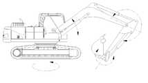
일반적으로 굴삭기는 땅을 파거나 깎을 때 사용되는 건설기계로 일반적으로 포크레인이라고도 한다. 이러한 굴삭기는, 도 1에 나타낸 바와 같이, 캐터필러식의 궤도체 위에 스윙몸체가 조종자가 원하는 스윙회전각만큼 회전가능하게 설치되고, 스윙몸체에 조종석이 형성되어 있다.In general, an excavator is a construction machine used for digging or mowing land. As shown in Fig. 1, such an excavator is provided with a swing body rotatably mounted on a caterpillar track body by a swing rotation angle desired by the operator, and a cockpit is formed on the swing body.
스윙몸체에 붙어있는 붐은 유압실린더에 의해 상하이동을 할 수 있고, 붐의 단부에는 아암이 유압실린더에 의해 회전가능하게 설치된다.The boom attached to the swing body can be moved by the hydraulic cylinder, and the arm is rotatably installed by the hydraulic cylinder at the end of the boom.
아암의 단부에는 버킷이 회전할 수 있게 설치되어 작업을 할 수 있게 되고, 버킷은 드래그라인, 클램셸, 드래그셔블 등으로 바꾸어서 토사와 암석의 상태, 굴착방법, 이동성에 따라 다양하게 사용할 수 있다.At the end of the arm, the bucket is rotatably installed to work, and the bucket can be changed to dragline, clamshell, drag shovel, etc., and can be used in various ways depending on the soil, rock condition, excavation method, and mobility.
이러한 굴삭기를 조종하기 위한 조종장치로서, 종래의 굴삭기 조종장치는 조이스틱을 이용하여 버킷의 인 앤 아웃, 아암의 업 앤 다운, 붐의 인 앤 아웃, 선회작업을 수행한다.As a control device for manipulating such an excavator, a conventional excavator control device uses a joystick to perform bucket in and out, arm up and down, boom in and out, and turning.
그러나, 굴삭기를 이용한 작업의 경우, 작업위치, 환경, 및 조건에 따라서는 위험한 지역이나 열악한 환경하에서 작업이 이루어지는 경우가 많고, 이러한 경우 조작자가 굴삭기에 탑승하여 조종하기가 매우 어려운 경우가 자주 발생한다. 이러한 상황하에서 조종자가 굴삭기에 직접 탑승하지 않고도 굴삭기의 제어가 가능한 원격제어 굴삭기 조종장치가 필요하다.However, in the case of a work using an excavator, the work is often performed in a dangerous area or in a bad environment depending on the work location, environment, and conditions, and in this case, it is often difficult for the operator to ride and control the excavator. . Under these circumstances, there is a need for a remote controlled excavator control unit that can control the excavator without the operator directly boarding the excavator.
한국특허공고 제1994-0003731호에는 원격제어 굴삭기 조종장치가 개시되어 있다. 상기 종래의 굴삭기 원격조종장치(100)는, 도 2에 나타낸 바와 같이, 프레임에 고정되며 모터축과 동일하게 회전할 수 있도록 가이드 슬롯을 갖는 두개의 원호형 가동부재(101a, 101b)와, 가동부재의 가이드 슬롯상에서 모터의 회전동작에 의해 조작되는 조작레버(101)를 구비하고 있다.Korean Patent Publication No. 1994-0003731 discloses a remote control excavator control device. The conventional excavator
그러나, 상술한 종래의 굴삭기 원격조종장치에 있어서는, 굴삭기의 버킷, 아암, 붐의 움직임이 조이스틱 및 레버의 움직임과 맵핑되지 않기 때문에, 조이스틱 및 레버를 조작하기 위해서는 상당한 숙련도가 요구된다고 하는 문제점이 있었다. 즉, 굴삭기의 버킷, 아암, 붐의 실제 움직임과 조작을 위한 조작레버의 실제 움직임이 상관성을 갖지 않고 있기 때문에, 능숙하지 않는 작업자에게는 혼동을 가져와 원하는 작업을 수행하는데 어려움을 가져올 수 있다.However, in the above-mentioned conventional excavator remote control device, since the movement of the bucket, the arm and the boom of the excavator is not mapped with the movement of the joystick and the lever, there is a problem that considerable skill is required to operate the joystick and the lever. . That is, since the actual movement of the bucket, the arm, the boom of the excavator and the actual movement of the operating lever for the operation does not have a correlation, it may bring confusion to the inexperienced worker and may cause difficulty in performing the desired work.
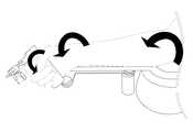
한편, 한국특허공개공보 제2011-0074061호에는 상술한 문제를 해결하기 위한 직관적 조종장치가 개시되어 있다. 상기 종래의 굴삭기의 직관적 조종장치는, 도 3에 나타낸 바와 같이, 굴삭기의 버킷, 아암, 붐의 움직임을 실제로 작업자의 손목, 하완, 상완의 움직임과 직관적으로 연관성을 갖도록 조종할 수 있으므로, 굴삭기의 유저 인터페이스 조종능력을 향상시켜 굴삭기를 자유롭게 조작함으로써 보다 빠르고 정확하게 능숙한 굴삭 작업을 구현할 수 있도록 구성한 조종장치가 개시되어 있다.On the other hand, Korean Patent Publication No. 2011-0074061 discloses an intuitive control device for solving the above problems. As shown in FIG. 3, the intuitive control device of the conventional excavator can control the movement of the bucket, arm and boom of the excavator to have an intuitive relationship with the movement of the wrist, lower arm and upper arm of the excavator. Disclosed is a control device configured to implement a fast and accurate skillful excavation work by improving the user interface control ability to freely operate an excavator.
그러나, 상기 종래기술에 있어서는, 조작자의 어깨를 사용하는 구조를 가지므로, 큰 근육을 사용하기 때문에 동일한 작업을 수행하더라도 조작자의 피로도가 크다고 하는 문제점이 있었다. 또한, 상기 종래기술에 있어서는 각각의 조작부가 역학적으로 결합되어 있어서 버킷 링크를 회전시키기 위해서는 손목 관절이 같이 회전하게 되어 붐, 아암이 함께 움직이므로 독립적인 구동이 어렵다고 하는 문제점이 있었다.However, in the above-described prior art, since it has a structure using the operator's shoulder, there is a problem that the operator's fatigue is great even if the same work is performed because a large muscle is used. In addition, in the prior art, each operation unit is mechanically coupled, and in order to rotate the bucket link, the wrist joints rotate together, so that the boom and the arm move together, so that independent driving is difficult.
또한, 상기 종래기술에 있어서는, 굴삭기의 붐, 아암, 버킷의 구동을 원격으로 할 수 있으나, 그 이외의 굴삭기의 구동, 예를 들면, 트랙의 전후좌우 구동이나, 굴삭기의 보조기구인 크러셔 구동 또는 굴삭기 몸체의 상체 스윙 동작구동 등 굴삭기의 다양한 구동에 대한 원격조종방법이 전혀 제시되지 않다고 하는 문제점이 있었다.
Moreover, in the said prior art, although the boom, the arm, and the bucket of an excavator can be driven remotely, the drive of other excavators, for example, the front, rear, left and right drive of a track, the crusher drive or excavator which are auxiliary tools of an excavator. There was a problem that the remote control method for various driving of the excavator, such as the upper body swing operation of the body is not presented at all.
본 발명은 상술한 종래기술의 문제점을 해결하고자 하는 것으로서, 본 발명의 목적은 사람의 팔, 손목, 손가락을 굴삭기의 붐 조인트, 아암 조인트, 버킷 조인트와 연동되도록 굴삭기의 링크 구조와 유사한 구조로 구성하여 초보자라도 굴삭기의 동작을 쉽게 인지할 수 있고 위치 제어를 기반으로 하여 조작자의 피로도를 줄여 편하게 조종할 수 있는 햅틱조종장치를 구비함과 동시에 굴삭기의 트랙구동이나 스윙 구동은 물론 보조기구인 크러셔의 장착 구동을 원격으로 조종할 수 있는 조이스틱이 구비된 굴삭기의 원격 조종시스템을 제공하는 것이다.
The present invention is to solve the above-mentioned problems of the prior art, the object of the present invention is to construct a structure similar to the link structure of the excavator so that the human arm, wrist, fingers interlock with the boom joint, arm joint, bucket joint of the excavator Even the beginners can easily recognize the operation of the excavator, and based on the position control, it is equipped with a haptic steering system that can be easily controlled by reducing the fatigue of the operator. It is to provide a remote control system of an excavator equipped with a joystick that can remotely control the drive.
상술한 목적을 달성하기 위하여, 본 발명에 의한 굴삭기의 원격조종 시스템은, 굴삭기의 붐 링크부와 연동되며, 조작자의 팔꿈치를 안착시키고 바닥면과 평행하게 회동가능한 붐 컨트롤부와, 굴삭기의 아암 링크부와 연동되며 상기 붐 컨트롤부와 동일 평면상에서 회동가능하도록 상기 붐 컨트롤부에 체결되는 아암 컨트롤부와, 굴삭기의 버킷 링크부와 연동되며 상기 아암 컨트롤부와 회동가능하도록 상기 아암 컨트롤부에 체결되는 버킷 컨트롤부를 포함하는 햅틱조종장치와, 굴삭기의 유압구동부에 연동되며 굴삭기의 트랙구동과 선회구동 및 크러셔 구동을 수행하는 복수의 원격조종장치를 구비하고, 상기 버킷 컨트롤부는, 조작자의 손가락이 삽입될 수 있는 파지부 유닛과, 상기 파지부 유닛을 안내하는 가이드 로드와, 상기 가이드 로드에 연결된 버킷 회전축과, 상기 버킷 회전축에 연결된 버킷 구동풀리와, 상기 버킷 구동풀리에 연결된 버킷 구동모터부와, 상기 버킷 회전축에 연결된 체결로드 및 상기 버킷 구동모터부를 지지하며 상기 아암 컨트롤부에 체결되는 버킷 체결부를 구비하는 것을 특징으로 한다.In order to achieve the above object, the remote control system of the excavator according to the present invention is interlocked with the boom link portion of the excavator, the boom control portion that seats the elbow of the operator and can be rotated in parallel with the bottom surface, the arm link of the excavator An arm control part coupled to the boom control part so as to be rotatable on the same plane as the boom control part, and linked to the bucket control part of the excavator and coupled to the arm control part to be rotatable with the arm control part. A haptic control device including a bucket control unit and a plurality of remote control devices that interlock with the hydraulic drive unit of the excavator and perform the track drive, the turning drive and the crusher drive of the excavator, the bucket control unit, the operator's finger is inserted A gripper unit, a guide rod for guiding the gripper unit, and a connection to the guide rod Bucket rotation shaft, the bucket drive pulley connected to the bucket rotation shaft, the bucket drive motor portion connected to the bucket drive pulley, the fastening rod connected to the bucket rotation shaft and the bucket drive motor portion, the bucket fastening is fastened to the arm control unit It is characterized by comprising a part.
여기서, 상기 복수의 원격조종장치는, 굴삭기의 트랙구동을 굴삭기의 선회구동 및 크러셔 구동과 독립적으로 수행하는 것을 특징으로 한다.Here, the plurality of remote control device, characterized in that to perform the track drive of the excavator independently of the swing drive and crusher driving of the excavator.
여기서, 상기 복수의 원격조종장치는, 전후좌우 조작에 의해 굴삭기의 전후좌우 트랙구동을 수행시키는 제 1 조이스틱과, 좌우 조작에 의해 굴삭기 몸체를 좌우 스윙구동시키고 전후조작에 의해 크러셔를 구동시키는 제 2 조이스틱을 포함하는 것을 특징으로 한다.Here, the plurality of remote control apparatus, the first joystick for performing the front, rear, left and right track driving of the excavator by the front, rear, left and right operation, and the second for driving the excavator body left and right swing by the left and right operation and driving the crusher by the front and rear operation It characterized in that it comprises a joystick.
또한, 상기 원격조종시스템은 굴삭기의 복수의 트랙구동레버에 연결되며 상기 제 1 조이스틱에 연동되는 복수의 트랙레버 구동부 및 복수의 트랙레버 구동모터와, 굴삭기의 크러셔 구동레버에 연결되며 상기 제 2 조이스틱에 연동되는 크러셔레버 구동부 및 크러셔레버 구동모터와, 굴삭기의 스윙레버에 연결되며 상기 제 2 조이스틱에 연동되는 스윙레버 구동부 및 스윙레버 구동모터를 구비하는 것을 특징으로 한다.
The remote control system may be connected to a plurality of track driving levers of an excavator and connected to a plurality of track lever driving units and a plurality of track lever driving motors linked to the first joystick, and to a crusher driving lever of the excavator, and to the second joystick. The crusher lever driving unit and the crusher lever driving motor interlocked to the swing lever of the excavator and the swing lever driving unit and the swing lever driving motor linked to the second joystick, characterized in that it comprises.
상술한 구성을 가지는 본 발명에 의한 굴삭기의 원격조종시스템에 의하면, 사람의 팔, 손목, 손가락을 굴삭기의 붐 조인트, 아암 조인트, 버킷 조인트와 연동되도록 조종장치를 굴삭기의 링크 구조와 유사한 구조로 구성하여 초보자라도 굴삭기의 동작을 쉽게 인지할 수 있도록 구성함과 동시에 조작자의 팔꿈치, 손목을 조종장치에 안착시키고 붐 컨트롤부, 아암 컨트롤부, 버킷 컨트롤부를 조작이 간편하도록 바닥면에 평행하게 회동할 수 있도록 위치 제어를 기반으로 하여 조작자의 피로도를 줄여 편하게 조종할 수 있고, 붐 링크, 아암 링크 및 버킷 링크를 각각 상대적으로 회동가능하며 독립적으로 구동될 수 있도록 구성함으로써, 보다 정확한 굴삭기의 조종이 가능하고, 조작자의 팔 길이에 따라 붐 컨트롤부, 아암 컨트롤부, 버킷 컨트롤부의 길이를 가변적으로 조절할 수 있도록 구성함으로써 사용이 편리하게 구성할 수 있다.According to the remote control system of the excavator according to the present invention having the above-described configuration, the manipulator has a structure similar to the link structure of the excavator so that the human arm, wrist, and fingers are interlocked with the boom joint, the arm joint, and the bucket joint of the excavator. By making it easy for beginners to recognize the operation of the excavator, the elbows and wrists of the operator can be seated on the control unit, and the boom control unit, arm control unit and bucket control unit can be rotated parallel to the floor for easy operation. Based on the position control, the operator's fatigue can be reduced and controlled. The boom link, the arm link, and the bucket link can be configured to be relatively rotatable and independently driven, so that the excavator can be operated more precisely. Depending on the length of the operator's arm, the length of the boom control, arm control and bucket control The use by configuring to adjust the variable can be easily configured.
또한, 하나의 조이스틱으로는 독립적으로 구동하는 굴삭기의 트랙구동을 원격 조종하고, 또 하나의 조이스틱으로는 구동에 있어서 서로 연관성이 높은 스윙구동과 크러셔의 장착 구동을 연계하여 원격으로 조종하도록 구성함으로써, 조작이 간편하고, 안전한 굴삭작업을 수행할 수 있다.
In addition, one joystick is configured to remotely control the track drive of an independently driven excavator, and another joystick is configured to remotely control the link drive of the crusher and the driving drive that are highly related to each other in driving. Simple operation and safe digging.
도 1은 굴삭기의 일반적 예를 나타내는 도면이다.
도 2 및 도 3은 종래기술에 의한 굴삭기의 조종장치를 나타내는 도면이다.
도 4는 본 발명에 의한 굴삭기의 원격조종시스템을 나타내는 도면이다.
도 5는 본 발명에 의한 햅틱 조종장치를 나타내는 도면이다.
도 6은 도 5의 햅틱조종장치를 사용하는 일 예를 나타내는 도면이다.
도 7a 및 7b는 본 발명에 의한 트랙구동부 및 트랙구동모터를 나타내는 도면이다.
도 8은 본 발명에 의한 크러셔 구동부 및 크러셔 구동모터를 나타내는 도면이다.
도 9는 본 발명에 의한 스윙 구동부 및 스윙구동모터를 나타내는 도면이다.1 is a view showing a general example of an excavator.
2 and 3 is a view showing the control device of the excavator according to the prior art.
4 is a view showing a remote control system of the excavator according to the present invention.
5 is a view showing a haptic control device according to the present invention.
6 is a diagram illustrating an example of using the haptic steering apparatus of FIG. 5.
7A and 7B are diagrams showing a track drive unit and a track drive motor according to the present invention.
8 is a view showing a crusher drive unit and a crusher drive motor according to the present invention.
9 is a view showing a swing drive unit and a swing drive motor according to the present invention.
이하, 첨부한 도면을 참조하여 본 발명에 의한 굴삭기의 원격 조종시스템에 대하여 실시예로써 상세하게 설명한다.
Hereinafter, with reference to the accompanying drawings, a remote control system for an excavator according to the present invention will be described in detail by way of example.
도 4 내지 도 9에 나타낸 바와 같이, 본 발명에 의한 굴삭기의 원격조종 시스템(1)은 굴삭기의 굴삭동작을 원격으로 조종하는 햅틱조종장치(2)와, 굴삭기의 굴삭동작 이외의 기본적인 구동동작을 원격으로 조종하는 복수의 원격조종장치(40, 50)와, 굴삭기를 원격으로 조종할 때에 원격지의 굴삭기의 작업현장을 모니터링할 수 있는 모니터부(3)를 포함한다.4 to 9, the
상기 햅틱조종장치(2)와 상기 복수의 원격조종장치(40, 50)와 상기 모니터부(3)는 도 4에 나타낸 바와 같이, 하나의 스테이션(4) 내에 설치될 수 있다.
The haptic steering apparatus 2, the plurality of
상기 햅틱조종장치(2)는 붐 컨트롤부(10)와, 아암 컨트롤부(20)와, 버킷 컨트롤부(30)를 구비하며, 굴삭기의 링크 구조와 유사한 구조로 구성되어 있다.The haptic steering apparatus 2 includes a
상기 붐 컨트롤부(10)는 굴삭기의 붐 링크부와 연동되며, 조작자의 팔꿈치를 안착시켜 지지한다. 상기 붐 컨트롤부(10)는, 도 5에 나타낸 바와 같이, 상기 햅틱조종장치가 설치되는 바닥면에 대하여 평행한 평면상에서 회동가능하게 설치되어 있다.The
상기 붐 컨트롤부(10)는 프레임(11)과, 붐 회전플레이트(12)와, 붐 구동풀리(13)와, 붐 구동모터(15)와, 가이드 플레이트(16)를 포함한다.The
상기 붐 회전플레이트(12)는 대략 원반 형상으로 형성되어 있고, 상기 프레임(11)에 지지되며, 상기 붐 회전플레이트의 상부에는 조작자가 팔꿈치를 얹어놓고 조작에 필요한 방향으로 좌우로 회전시킴에 따라 회전할 수 있도록 구성되어 있다.The
상기 붐 회전플레이트(12)의 하부에는 붐 구동회전축이 체결되어 있으며 상기 붐 구동회전축의 하부에는 붐 구동풀리(13)가 체결되어 있으며, 상기 붐 구동풀리는 타이밍벨트 등에 의해 붐 구동모터(15)의 회전축(14)에 연결되어 있다.The boom drive rotary shaft is fastened to the lower portion of the
상기 붐 회전플레이트(12)에는 가이드 플레이트(16)가 일체로 형성되어 있다. 상기 가이드 플레이트(16)의 양측면에는 복수 개의 제 1 가변체결홀(17)이 일정간격 이격되어 형성되어 있다. 상기 가이드 플레이트에는 후술하는 아암 플레이트를 삽입시킬 수 있고, 상기 제 1 가변체결홀(17)과 아암 플레이트에 형성된 복수의 체결구멍을 위치맞춤한 후에 볼트나 나사 등의 고정수단에 의해 고정할 수 있도록 구성된다. 이로써, 상기 원격조종장치를 사용하는 조작자의 팔길이에 따라 상기 가이드 플레이트에 아암 플레이트를 삽입한 후 원하는 길이에 맞춘 다음, 상기 제 1 가변체결홀과 체결구멍을 위치맞춤하여 길이를 조절할 수 있다.
또한, 상기 가이드 플레이트(16)의 상기 붐 회전플레이트의 반대쪽 끝단에는 가이드 홈을 형성하고, 상기 가이드 홈이 형성된 부분의 상기 가이드 플레이트의 바닥면은 내부측으로 돌출되도록 돌출부를 형성할 수 있다. 상기 돌출부에 의해 상기 가이드 플레이트에 삽입되는 아암 플레이트가 지지될 수 있도록 구성하고, 상기 가이드 홈에 아암플레이트 지지부가 삽입되어 이동될 수 있도록 구성한다.In addition, a guide groove may be formed at the opposite end of the boom rotation plate of the
또한, 상기 회전플레이트와 상기 가이드 플레이트의 상부면에는 조작자의 팔꿈치 받침대로서 커버를 설치할 수 있다.In addition, a cover may be installed on the upper surface of the rotating plate and the guide plate as an elbow rest of the operator.
상술한 구성을 가지는 붐 컨트롤부는, 조작자가 상기 회전플레이트에 팔꿈치를 얹어놓고 평면상으로 회전시키면, 이에 따라 상기 회전플레이트가 회전하게 되고, 상기 회전플레이트에 동축으로 연결된 붐 구동회전축이 회전구동되어, 상기 붐 구동풀리를 통해 붐 구동모터의 회전축이 회전하게 된다. 붐 구동모터의 회전축의 회전에 따라 붐 구동모터의 회전에 의한 전류값이 측정되어 상기 원격조종장치의 제어부를 통해 굴삭기의 조종장치에 전송되어 굴삭기의 붐 링크부를 구동시키게 된다.When the operator puts the elbows on the rotating plate and rotates the plane, the boom control unit having the above-described configuration rotates the rotating plate accordingly, and the boom driving rotating shaft coaxially connected to the rotating plate is driven to rotate. The rotating shaft of the boom drive motor is rotated through the boom drive pulley. According to the rotation of the rotary shaft of the boom drive motor current value by the rotation of the boom drive motor is measured and transmitted to the control device of the excavator through the control unit of the remote control device to drive the boom link of the excavator.
상기 붐 컨트롤부에는 아암 컨트롤부(20)가 연결된다. 상기 아암 컨트롤부(20)는 굴삭기의 아암 링크부와 연동되며 상기 붐 컨트롤부와 동일 평면상에서 회동가능하도록 구성된다.The
상기 아암 컨트롤부(20)는, 아암 플레이트(21)와, 아암 구동풀리(22)와, 아암 구동모터(23)와, 아암 회전플레이트(24)를 구비한다.The
상기 아암 플레이트(21)의 일끝단은 상기 붐 컨트롤부의 상기 가이드 플레이트에 체결되고 타끝단은 조작자의 손목을 안착시켜 지지하도록 구성된다.One end of the
조작자의 손목을 지지하는 상기 아암 플레이트(21)의 타끝단의 하부에는 회전축이 연결되어 있고, 상기 회전축에는 아암 구동풀리(22)가 연결되어 있다. 상기 아암 구동풀리(22)는 타이밍벨트 등에 의해 아암 구동모터(23)의 회전축과 연결되어 있다.The lower end of the other end of the
또한, 상기 아암 플레이트(21)의 하부에는 아암 구동모터에 연결되어 아암 구동모터를 지지하는 아암 지지플레이트(21a)가 지지브라켓(21b)에 의해 연결되어 있다. 상술한 바와 같이, 조작자의 팔길이에 따라 상기 아암 플레이트가 상기 가이드 플레이트에 삽입되는 길이를 조절할 때에, 상기 지지브라켓은 상기 가이드 홈에 삽입되고 상기 아암 구동모터와 상기 아암 플레이트가 함께 안내되어 이동할 수 있도록 구성된다.In addition, an
상기 아암플레이트의 양측에는 상기 제 1 가변체결홀에 상응하는 복수의 체결구멍이 형성되어 있다.A plurality of fastening holes corresponding to the first variable fastening holes are formed at both sides of the arm plate.
또한, 상기 아암 플레이트와 상기 아암 구동풀리 사이에는 아암 회전플레이트(24)가 설치된다. 상기 아암 회전플레이트(24)는 상기 아암 플레이트의 회전축에 회동가능하게 연결되어, 도 6에 나타낸 바와 같이, 사용자가 손목을 회전시킴에 따라 상기 아암 플레이트와 동일 평면상에서 회전가능하게 구성된다.In addition, an
상기 아암 회전플레이트의 타측에는 복수의 제 2 가변체결홀(25)이 일정간격 이격되어 형성되어 있다. 상기 제 2 가변체결홀에는 후술하는 버킷 컨트롤부의 체결 브라켓이 체결되며, 조작자의 손목의 길이에 따라 상기 체결 브라켓의 체결 위치를 조절할 수 있다.On the other side of the arm rotating plate, a plurality of second variable fastening holes 25 are formed at regular intervals. The fastening bracket of the bucket control unit to be described later is fastened to the second variable fastening hole, and the fastening position of the fastening bracket can be adjusted according to the length of the wrist of the operator.
상술한 구성을 가지는 아암 컨트롤부는, 조작자가 상기 아암 플레이트에 손목을 얹어놓고 평면상으로 회전시키면, 이에 따라 상기 아암 회전플레이트가 회전하게 되고, 상기 아암 회전플레이트에 동축으로 연결된 아암 구동회전축이 회전구동되어, 상기 아암 구동풀리를 통해 아암 구동모터의 회전축이 회전하게 된다. 아암 구동모터의 회전축의 회전에 따라 아암 구동모터의 회전에 의한 전류값이 측정되어 상기 원격조종장치의 제어부를 통해 굴삭기의 조종장치에 전송되어 굴삭기의 아암 링크부를 구동시키게 된다.
The arm control unit having the above-described configuration, when the operator puts the wrist on the arm plate and rotates in a plane, the arm rotation plate is rotated accordingly, the arm drive rotation shaft coaxially connected to the arm rotation plate is driven to rotate The rotation axis of the arm drive motor is rotated through the arm drive pulley. As the rotation axis of the arm drive motor is rotated, a current value due to the rotation of the arm drive motor is measured and transmitted to the control device of the excavator through a control unit of the remote control device to drive the arm link part of the excavator.
상기 아암 회전플레이트에는 버킷 컨트롤부(30)가 연결된다. 상기 버킷 컨트롤부(30)는 굴삭기의 버킷 링크부와 연동되며 상기 아암 컨트롤부와 동일 평면상에서 회동가능하도록 구성된다.
상기 버킷 컨트롤부(30)는, 도 6 및 도 7에 나타낸 바와 같이, 파지부 유닛(31)과, 가이드로드(32)와, 버킷 회전축(33)과, 버킷 구동풀리(34)와, 버킷 체결부(36)와, 버킷 구동모터부(37)를 포함하여 구성된다.As shown in FIG. 6 and FIG. 7, the
상기 파지부 유닛(31)은 상기 가이드로드(32)가 삽입되는 삽입구멍이 형성되어 있고, 상기 파지부 유닛(31)의 하부에는 도 8에 나타낸 바와 같이 조작자의 손가락을 끼워넣을 수 있도록 하단부가 개구되어 대략 n자 형상으로 형성된 파지부(31a)가 형성되어 있다. 조작자가 상기 파지부에 손가락을 끼워넣으면 조작자의 손가락의 길이에 따라, 상기 파지부 유닛(31)은 상기 가이드로드를 따라 전후로 슬라이딩 이동한다.The gripping
상기 가이드로드(32)의 일끝단은 유닛 체결브라켓(32a)에 체결되며, 상기 유닛 체결브라켓은 상기 버킷 회전축(33)에 회전가능하게 체결된다.One end of the
상기 버킷 회전축(33)은 체결로드(35)에 의해 지지되며, 상기 버킷 회전축(33)에는 버킷 구동풀리(34)가 동축으로 연결되어 있고, 상기 버킷 구동풀리(34)는 타이밍벨트 등에 의해 버킷 구동모터부(37)의 회전축과 연결되어 있다.The
상기 버킷 구동모터부(37)의 내부에는 버킷 구동모터가 내장되어 있고, 상기 버킷 구동모터부(37)의 케이스의 외부면에는 조작자가 파지하기 용이하도록 손잡이부(38)가 마련되어 있다.A bucket drive motor is built in the bucket
상기 버킷 구동모터부(37)는 버킷 체결부(36)에 체결된다. 상기 버킷 체결부의 상부측에는 연결브라켓(36a)을 통해 상기 체결로드가 지지되며, 상기 버킷 체결부(36)는 체결 브라켓(39)를 통해 상기 아암 회전플레이트(24)에 세워 설치된다. 상기 버킷 체결부(36)의 하부에는, 예를 들면 힌지구멍이 형성되어 힌지핀 등에 의해 상기 체결 브라켓(39)에 회동가능하게 체결되며, 상기 체결 브라켓(39)은 상기 아암 회전플레이트에 회동가능하게 체결된다.The bucket driving
이로써, 상기 버킷 컨트롤부는, 도 6에 나타낸 바와 같이, X축 및 Y축을 중심으로 회전가능하도록 2자유도를 갖는 구조로 구성되어 조작자가 상기 손잡이를 잡고 편하게 조작할 수 있도록 구성되어 있다.Thus, the bucket control unit, as shown in Figure 6, is configured in a structure having two degrees of freedom so as to be rotatable about the X-axis and Y-axis is configured to allow the operator to hold the handle and operate comfortably.
상술한 구성을 가지는 버킷 컨트롤부는, 조작자가 상기 파지부에 손가락을 끼워넣고 평면상으로 회전시키면, 이에 따라 상기 파지부 유닛이 회전하게 되고, 상기 파지부 유닛의 회전에 따라 버킷 회전축이 회전구동되어, 상기 버킷 구동풀리를 통해 버킷 구동모터의 회전축이 회전하게 된다. 버킷 구동모터의 회전축의 회전에 따라 버킷 구동모터의 회전에 의한 전류값이 측정되어 상기 원격조종장치의 제어부를 통해 굴삭기의 조종장치에 전송되어 굴삭기의 버킷 링크부를 구동시키게 된다.
The bucket control unit having the above-described configuration, when the operator inserts a finger into the holding portion and rotates in a plane, the holding unit rotates accordingly, and the bucket rotating shaft rotates according to the rotation of the holding unit. The rotating shaft of the bucket driving motor is rotated through the bucket driving pulley. According to the rotation of the rotating shaft of the bucket drive motor current value by the rotation of the bucket drive motor is measured and transmitted to the control device of the excavator through the control unit of the remote control device to drive the bucket link portion of the excavator.
한편, 본 발명의 굴삭기 원격조종시스템(1)은 상기 햅틱조종장치 이외에 복수의 원격조종장치(40, 50)를 구비한다. 본 실시예에 있어서, 상기 복수의 원격조종장치(40, 50)는 상기 햅틱조종장치에 의한 굴삭기의 굴삭구동 이외에 굴삭기의 다른 구동, 예를 들면 굴삭기의 트랙구동이나, 선회구동, 크러셔 구동을 수행하도록 구성될 수 있다.Meanwhile, the excavator
여기서, 상기 복수의 원격조종장치는, 가장 직관적으로 조종이 가능한 트랙의 구동 동작을 하나의 원격조종장치에서 수행하도록 구성하고, 서로 독립적으로 구동이 이루어지는 선회구동이나 크러셔 구동은 서로 같은 하나의 원격조종장치에서 수행하도록 구성되는 것이 바람직하다.Here, the plurality of remote control device is configured to perform the drive operation of the most intuitively controlled track in one remote control device, the rotational drive or crusher driving is driven independently of each other is the same remote control It is preferably configured to perform in the device.
상기 복수의 원격조종장치는, 제 1 조이스틱(40)과 제 2 조이스틱(50)을 포함하여 구성되며, 상기 제 1 조이스틱 및 상기 제 2 조이스틱은 상기 햅틱조종장치의 일측에 서로 병렬되어 배치된다.The plurality of remote control devices include a
상기 제 1 조이스틱(40)은, 전후좌우 조작에 의해 굴삭기의 전후좌우 트랙구동을 수행시킨다. 상기 제 1 조이스틱(40)은 굴삭기의 유압구동부에 연결된 트랙구동레버에 연결되어, 상기 제 1 조이스틱(40)을 전후로 조작함에 따라 굴삭기가 전후로 트랙구동하게 된다. 또한, 상기 제 1 조이스틱(40)을 좌우로 조작함에 따라, 상기 제 1 조이스틱(40)의 좌우조작신호를 인가받은 제어부는 굴삭기의 좌우측 트랙에 연결된 레버의 조작정도를 달리하도록 미리 설정된 값에 따라 굴삭기의 좌우측 트랙레버의 전진 속도를 달리 적용하도록 구성되어 좌우측으로 트랙구동할 수 있도록 구성되어 있다.The
상기 제 2 조이스틱(50)은, 좌우조작에 의해서 상기 굴삭기의 몸체를 좌우로 스윙구동하고, 전후조작에 의해서 상기 굴삭기의 크러셔를 구동시킨다.The
여기서, 일반적으로 굴삭기의 구동에 있어서는 굴삭기 몸체의 스윙동작과 크러셔 구동동작이 서로 독립적으로 이루어지기 때문에, 상기 제 2 조이스틱 하나로써 상기 스윙구동과 상기 크러셔 구동이 이루어지도록 구성할 수 있다.
Here, in general, in the driving of the excavator, since the swing operation and the crusher driving operation of the excavator body are performed independently of each other, the swing driving and the crusher driving may be performed by the second joystick.
한편, 굴삭기 본체의 각각의 구동레버에는 상기 제 1 조이스틱 및 상기 제 2 조이스틱에 연동되는 구동부 및 구동모터를 설치하여, 상기 구동부 및 구동모터와 상기 제 1 및 제 2 조이스틱이 서로 연동되도록 구성할 수 있다.On the other hand, each drive lever of the excavator body is provided with a drive unit and a drive motor interlocked with the first joystick and the second joystick, the drive unit and the drive motor and the first and second joystick can be configured to interlock with each other. have.
도 7a 및 도 7b에 나타낸 바와 같이, 상기 제 1 조이스틱에는 한 쌍의 트랙레버구동부(62, 72) 및 한 쌍의 트랙레버 구동모터(61, 71)가 연동된다. 상기 트랙레버 구동부(62, 72)는 각각 굴삭기의 좌우측 트랙에 연결된 한 쌍의 트랙구동레버(60, 70)에 각각 연결되어 있고, 상기 트랙레버 구동부(62, 72)의 일측에는 각각 트랙레버 구동모터(61, 71)가 연결되어 있다. 상기 트랙레버 구동부(62, 72)는 예를 들면 유압실린더나 공압실린더로 구성되어 상기 트랙레버 구동모터의 구동에 의해 실린더 로드가 전후로 이동된다.As shown in Figs. 7A and 7B, a pair of track
상기 트랙레버 구동부의 상기 실린더 로드의 끝단에는 제 1 연결링크(63a, 73a)가 연결되어 있고, 상기 제 1 연결링크(63a, 73a)는 제 1 및 제 2 연결힌지(63b, 73b)에 회동가능하게 연결되며, 상기 제 1 및 제 2 연결힌지에는 상기 트랙구동레버에 연결된 제 2 연결링크(63c, 73c)가 각각 연결되어 있다.
이로써, 상기 제 1 조이스틱의 전후좌우 조작에 따라 상기 제 1 조이스틱으로부터 조작신호를 인가받은 제어부는 상기 트랙레버 구동모터를 구동시키고, 상기 트랙레버 구동모터의 구동에 의해 상기 트랙레버 구동부의 실린더 로드가 전후로 이동되며, 상기 실린더 로드의 전후이동에 의해 상기 실린더 로드에 제 1연결링크, 연결힌지, 제 2 연결링크를 통해 연결된 트랙구동레버가 전후로 조작이동된다.
As a result, the control unit receiving the operation signal from the first joystick according to the front, rear, left and right operation of the first joystick drives the track lever driving motor, and the cylinder rod of the track lever driving unit is driven by the track lever driving motor. It is moved back and forth, and the track driving lever connected to the cylinder rod through the first connecting link, the connecting hinge, the second connecting link by the front and rear movement of the cylinder rod is moved back and forth.
도 8 및 도 9에 나타낸 바와 같이, 굴삭기의 크러셔 레버에 연결되며 상기 제 2 조이스틱에 연동되는 크러셔 구동부 및 크러셔 구동모터와, 굴삭기의 스윙레버에 연결되며 상기 제 2 조이스틱에 연동되는 스윙구동부 및 스윙 구동모터를 구비하는 것을 특징으로 한다.8 and 9, a crusher drive and a crusher drive motor connected to the crusher lever of the excavator and interlocked with the second joystick, a swing drive unit and a swing connected to the swing lever of the excavator and interlocked with the second joystick It is characterized by including a drive motor.
상기 제 2 조이스틱에는 크러셔 구동부(82), 크러셔 구동모터(81), 스윙 구동부(92), 스윙구동모터(91)가 연동된다.The
상기 크러셔레버 구동부(82)는 굴삭기의 크러셔 구동레버(80)에 연결되어 있고, 상기 크러셔레버 구동부(82)의 일측에는 크러셔레버 구동모터(81)이 연결되어 있다. 상기 크러셔레버 구동부(82)는 예를 들면 유압실린더나 공압실린더로 구성되어 상기 크러셔레버 구동모터의 구동에 의해 실린더 로드가 전후로 이동된다.The crusher
상기 크러셔레버 구동부의 상기 실린더 로드의 끝단에는 제 3 연결링크(83a)가 연결되어 있고, 상기 제 3 연결링크(83a)는 제 3 연결힌지(83b)에 회동가능하게 연결되며, 상기 제 3 연결힌지에는 상기 크러셔 구동레버에 연결된 제 4연결링크(83c)가 연결되어 있다.A third connecting
상기 스윙레버 구동부(92)는 굴삭기의 스윙레버(90)에 연결되어 있고, 상기 스윙레버 구동부(92)의 일측에는 스윙레버 구동모터(91)이 연결되어 있다. 상기 스윙레버 구동부(92)는 예를 들면 유압실린더나 공압실린더로 구성되어 상기 스윙레버 구동모터의 구동에 의해 실린더 로드가 전후로 이동된다.The swing
상기 스윙레버 구동부의 상기 실린더 로드의 끝단에는 제 5 연결링크(93a)가 연결되어 있고, 상기 제 5 연결링크(93a)는 제 4 연결힌지(93b)에 회동가능하게 연결되며, 상기 제 4 연결힌지에는 상기 스윙레버에 연결된 제 6 연결링크(83c)가 연결되어 있다.A fifth connecting
상기 제 2 조이스틱의 전후 조작에 따라 상기 제 2 조이스틱으로부터 조작신호를 인가받은 제어부는 상기 크러셔레버 구동모터를 구동시키고, 상기 크러셔레버 구동모터의 구동에 의해 상기 크러셔레버 구동부의 실린더 로드가 전후로 이동되며, 상기 실린더 로드의 전후이동에 의해 상기 실린더 로드에 제 3 연결링크, 제 3 연결힌지, 제 4 연결링크를 통해 연결된 크러셔구동 레버가 전후로 조작이동되고, 상기 제 2 조이스틱의 좌우 조작에 따라 상기 제 2 조이스틱으로부터 조작신호를 인가받은 제어부는 상기 스윙레버 구동모터를 구동시키고, 상기 스윙레버 구동모터의 구동에 의해 상기 스윙레버 구동부의 실린더 로드가 전후로 이동되며, 상기 실린더 로드의 전후이동에 의해 상기 실린더 로드에 제 5 연결링크, 제 4 연결힌지, 제 6 연결링크를 통해 연결된 스윙레버가 전후로 조작이동된다.
The control unit receiving the operation signal from the second joystick according to the front and rear operation of the second joystick drives the crusher lever driving motor, and the cylinder rod of the crusher lever driving unit is moved back and forth by driving the crusher lever driving motor. The crusher driving lever connected to the cylinder rod through the third connecting link, the third connecting hinge, and the fourth connecting link is moved back and forth by the front and rear movement of the cylinder rod. 2, the control unit receiving the operation signal from the joystick drives the swing lever driving motor, and the cylinder rod of the swing lever driving unit is moved back and forth by driving the swing lever driving motor, and the cylinder is moved back and forth by the cylinder rod. Through the fifth connecting link, the fourth connecting hinge, the sixth connecting link to the rod A connected swing lever is moved back and forth operations.
이로써, 본 발명에 의한 굴삭기의 원격조종시스템에 의하면, 햅틱조종장치에 의하여 초보자라도 굴삭기의 동작을 쉽게 인지할 수 있도록 구성함과 동시에 위치 제어를 기반으로 하여 조작자의 피로도를 줄여 편하게 조종할 수 있고, 보다 정확한 굴삭기의 조종이 가능하며, 하나의 조이스틱으로는 독립적으로 구동하는 굴삭기의 트랙구동을 원격 조종하고, 또 하나의 조이스틱으로는 구동에 있어서 서로 연관성이 높은 스윙구동과 크러셔의 장착 구동을 연계하여 원격으로 조종하도록 구성함으로써, 조작이 간편하고, 안전한 굴삭작업을 수행할 수 있다.
Thus, according to the remote control system of the excavator according to the present invention, the haptic control device is configured so that even beginners can easily recognize the operation of the excavator and at the same time can be easily controlled by reducing the fatigue of the operator based on the position control In addition, it is possible to control the excavator more precisely, and one joystick can remotely control the track drive of the independently driven excavator, and another joystick connects the highly related swing drive and the crusher mounted drive. By remotely configured to control, it is easy to operate and can perform a safe excavation work.
1 : 굴삭기의 원격조종시스템
2 : 햅틱조종장치
3 : 모니터부
4 : 스테이션
40 : 제 1 조이스틱
50 : 제 2 조이스틱1: remote control system of excavator
2: Haptic steering device
3: monitor
4: station
40: first joystick
50: second joystick
Claims (4)
Translated fromKorean굴삭기의 유압구동부에 연동되며 굴삭기의 트랙구동과 선회구동 및 크러셔 구동을 수행하는 복수의 원격조종장치를 구비하고,
상기 버킷 컨트롤부는,
조작자의 손가락이 삽입될 수 있는 파지부 유닛과,
상기 파지부 유닛을 안내하는 가이드 로드와,
상기 가이드 로드에 연결된 버킷 회전축과, 상기 버킷 회전축에 연결된 버킷 구동풀리와,
상기 버킷 구동풀리에 연결된 버킷 구동모터부와,
상기 버킷 회전축에 연결된 체결로드 및 상기 버킷 구동모터부를 지지하며 상기 아암 컨트롤부에 체결되는 버킷 체결부;를 구비하는 것을 특징으로 하는 굴삭기의 원격조종 시스템.
A boom control part interlocked with the boom link part of the excavator, the boom control part seating the elbow of the operator and pivoting in parallel with the bottom surface, and interlocking with the arm link part of the excavator and rotatable on the same plane as the boom control part. A haptic steering apparatus including an arm control unit coupled to the bucket control unit and a bucket control unit interlocked with the bucket link unit of the excavator and coupled to the arm control unit to be rotatable with the arm control unit;
It is linked to the hydraulic drive of the excavator and has a plurality of remote control devices for performing track drive and swing drive and crusher drive of the excavator,
The bucket control unit,
A gripper unit into which an operator's finger can be inserted,
A guide rod for guiding the holding unit;
A bucket rotating shaft connected to the guide rod, a bucket driving pulley connected to the bucket rotating shaft,
A bucket driving motor unit connected to the bucket driving pulley;
And a bucket fastening part supporting the fastening rod connected to the bucket rotating shaft and the bucket driving motor part and fastened to the arm control part.
The remote control system of claim 1, wherein the plurality of remote control devices perform track driving of the excavator independently of turning and crusher driving of the excavator.
전후좌우 조작에 의해 굴삭기의 전후좌우 트랙구동을 수행시키는 제 1 조이스틱과,
좌우 조작에 의해 굴삭기 몸체를 좌우 스윙구동시키고 전후조작에 의해 크러셔를 구동시키는 제 2 조이스틱을 포함하는 것을 특징으로 하는 굴삭기의 원격조종 시스템.
The method of claim 2, wherein the plurality of remote control device,
A first joystick which performs the front, rear, left and right track driving of the excavator by front, rear, left and right operation,
And a second joystick configured to swing the excavator body left and right by left and right operation and drive the crusher by front and rear operation.
굴삭기의 복수의 트랙구동레버에 연결되며 상기 제 1 조이스틱에 연동되는 복수의 트랙레버구동부 및 복수의 트랙레버구동모터와,
굴삭기의 크러셔 구동레버에 연결되며 상기 제 2 조이스틱에 연동되는 크러셔레버 구동부 및 크러셔레버 구동모터와,
굴삭기의 스윙레버에 연결되며 상기 제 2 조이스틱에 연동되는 스윙레버구동부 및 스윙레버 구동모터를 구비하는 것을 특징으로 하는 굴삭기의 원격조종 시스템.
The method of claim 3, wherein
A plurality of track lever driving units and a plurality of track lever driving motors connected to the plurality of track driving levers of the excavator and linked to the first joystick;
A crusher lever driving unit and a crusher lever driving motor connected to the crusher driving lever of the excavator and interlocked with the second joystick;
And a swing lever driving unit and a swing lever driving motor connected to the swing lever of the excavator and interlocked with the second joystick.
Priority Applications (2)
| Application Number | Priority Date | Filing Date | Title |
|---|---|---|---|
| KR1020110144528AKR101369840B1 (en) | 2011-12-28 | 2011-12-28 | Remote control system for excabator |
| PCT/KR2012/009693WO2013100356A1 (en) | 2011-12-28 | 2012-11-15 | Remote control system for excavator |
Applications Claiming Priority (1)
| Application Number | Priority Date | Filing Date | Title |
|---|---|---|---|
| KR1020110144528AKR101369840B1 (en) | 2011-12-28 | 2011-12-28 | Remote control system for excabator |
Publications (2)
| Publication Number | Publication Date |
|---|---|
| KR20130076101A KR20130076101A (en) | 2013-07-08 |
| KR101369840B1true KR101369840B1 (en) | 2014-03-06 |
Family
ID=48697771
Family Applications (1)
| Application Number | Title | Priority Date | Filing Date |
|---|---|---|---|
| KR1020110144528AActiveKR101369840B1 (en) | 2011-12-28 | 2011-12-28 | Remote control system for excabator |
Country Status (2)
| Country | Link |
|---|---|
| KR (1) | KR101369840B1 (en) |
| WO (1) | WO2013100356A1 (en) |
Cited By (1)
| Publication number | Priority date | Publication date | Assignee | Title |
|---|---|---|---|---|
| EP3434830A3 (en)* | 2017-07-25 | 2019-05-15 | Liebherr-Hydraulikbagger GmbH | Operating device for a working machine |
Families Citing this family (6)
| Publication number | Priority date | Publication date | Assignee | Title |
|---|---|---|---|---|
| KR101550131B1 (en)* | 2014-01-20 | 2015-09-03 | 한양대학교 에리카산학협력단 | Unmanned controlling system of joystick to be applied to machinery |
| JP6922806B2 (en) | 2018-03-23 | 2021-08-18 | コベルコ建機株式会社 | Remote control system and main control device |
| CN108396809A (en)* | 2018-04-08 | 2018-08-14 | 梅瑞 | A kind of excavator simple, intuitive control operating system |
| CN114020090A (en)* | 2021-09-15 | 2022-02-08 | 浙江钱塘机器人及智能装备研究有限公司 | Electrically controlled reversing connecting rod control operating rod mechanism |
| CN115726345B (en)* | 2022-11-16 | 2025-05-02 | 南京工业大学 | An excavator for harsh working conditions with auxiliary control structure |
| KR102788179B1 (en)* | 2024-11-20 | 2025-03-31 | 주식회사 강산이앤지 | Safety assurance device for pruning trees around special high-voltage distribution lines and roads and pruning method using the device |
Citations (4)
| Publication number | Priority date | Publication date | Assignee | Title |
|---|---|---|---|---|
| JPH09316934A (en)* | 1996-05-24 | 1997-12-09 | Hitachi Constr Mach Co Ltd | Radio control equipment for civil engineering and construction machinery |
| JPH10277976A (en)* | 1997-04-07 | 1998-10-20 | Fujita Corp | Remote control system |
| JPH11350535A (en)* | 1998-06-11 | 1999-12-21 | Kyushu Regional Constr Bureau Ministry Of Constr | Remote control system |
| KR20110074061A (en)* | 2009-12-24 | 2011-06-30 | 고려대학교 산학협력단 | Intuitive controls of the excavator |
Family Cites Families (3)
| Publication number | Priority date | Publication date | Assignee | Title |
|---|---|---|---|---|
| JP2000038744A (en)* | 1998-07-22 | 2000-02-08 | Toa Harbor Works Co Ltd | Remote control method and device for backhoe |
| JP2005171510A (en)* | 2003-12-08 | 2005-06-30 | Hitachi Constr Mach Co Ltd | Operating device and work vehicle |
| JP2007191888A (en)* | 2006-01-18 | 2007-08-02 | Shin Caterpillar Mitsubishi Ltd | Work machine operating device |
- 2011
- 2011-12-28KRKR1020110144528Apatent/KR101369840B1/enactiveActive
- 2012
- 2012-11-15WOPCT/KR2012/009693patent/WO2013100356A1/enactiveApplication Filing
Patent Citations (4)
| Publication number | Priority date | Publication date | Assignee | Title |
|---|---|---|---|---|
| JPH09316934A (en)* | 1996-05-24 | 1997-12-09 | Hitachi Constr Mach Co Ltd | Radio control equipment for civil engineering and construction machinery |
| JPH10277976A (en)* | 1997-04-07 | 1998-10-20 | Fujita Corp | Remote control system |
| JPH11350535A (en)* | 1998-06-11 | 1999-12-21 | Kyushu Regional Constr Bureau Ministry Of Constr | Remote control system |
| KR20110074061A (en)* | 2009-12-24 | 2011-06-30 | 고려대학교 산학협력단 | Intuitive controls of the excavator |
Cited By (1)
| Publication number | Priority date | Publication date | Assignee | Title |
|---|---|---|---|---|
| EP3434830A3 (en)* | 2017-07-25 | 2019-05-15 | Liebherr-Hydraulikbagger GmbH | Operating device for a working machine |
Also Published As
| Publication number | Publication date |
|---|---|
| KR20130076101A (en) | 2013-07-08 |
| WO2013100356A1 (en) | 2013-07-04 |
Similar Documents
| Publication | Publication Date | Title |
|---|---|---|
| KR101369840B1 (en) | Remote control system for excabator | |
| KR100240085B1 (en) | Excavator controls | |
| JP4469239B2 (en) | Operation equipment for work machines | |
| CN109863273B (en) | System and method for defining an operating region of a lifting arm | |
| US7635045B2 (en) | Machine tool control console | |
| KR101553200B1 (en) | Hydraulic shovel | |
| KR101369839B1 (en) | Teleoperating device for excabator and force feedback control method for the same | |
| EP3704314B1 (en) | Excavator man-lift | |
| JPH09268602A (en) | Controller for excavator | |
| RU2008120399A (en) | WORKING MACHINE | |
| JP2003184132A (en) | Operation lever equipment for construction machinery | |
| JP2015188957A (en) | Remote control system of work machine | |
| JP2007191888A (en) | Work machine operating device | |
| US5497568A (en) | Integrated group of excavator control assemblies | |
| JP2025082364A (en) | Operation lever and construction machine | |
| KR101154777B1 (en) | Intuitive control device for excavator | |
| JP4587848B2 (en) | Operation equipment for work machines | |
| US20210331307A1 (en) | Controller, adjustment device, and adjustment system | |
| JP3657894B2 (en) | Manual operation of hydraulic excavator | |
| JP6441734B2 (en) | Working machine | |
| JP3207771B2 (en) | Hydraulic working machine | |
| JP5600830B2 (en) | Operation control device for work machine | |
| JP6479587B2 (en) | Remote control device for work machines | |
| JP6441157B2 (en) | Working machine | |
| JP6026143B2 (en) | Swivel work machine |
Legal Events
| Date | Code | Title | Description |
|---|---|---|---|
| A201 | Request for examination | ||
| PA0109 | Patent application | Patent event code:PA01091R01D Comment text:Patent Application Patent event date:20111228 | |
| PA0201 | Request for examination | ||
| E902 | Notification of reason for refusal | ||
| PE0902 | Notice of grounds for rejection | Comment text:Notification of reason for refusal Patent event date:20130617 Patent event code:PE09021S01D | |
| PG1501 | Laying open of application | ||
| E701 | Decision to grant or registration of patent right | ||
| PE0701 | Decision of registration | Patent event code:PE07011S01D Comment text:Decision to Grant Registration Patent event date:20131226 | |
| N231 | Notification of change of applicant | ||
| PN2301 | Change of applicant | Patent event date:20140212 Comment text:Notification of Change of Applicant Patent event code:PN23011R01D | |
| GRNT | Written decision to grant | ||
| PR0701 | Registration of establishment | Comment text:Registration of Establishment Patent event date:20140226 Patent event code:PR07011E01D | |
| PR1002 | Payment of registration fee | Payment date:20140226 End annual number:3 Start annual number:1 | |
| PG1601 | Publication of registration | ||
| FPAY | Annual fee payment | Payment date:20170109 Year of fee payment:4 | |
| PR1001 | Payment of annual fee | Payment date:20170109 Start annual number:4 End annual number:4 | |
| FPAY | Annual fee payment | Payment date:20180108 Year of fee payment:5 | |
| PR1001 | Payment of annual fee | Payment date:20180108 Start annual number:5 End annual number:5 | |
| FPAY | Annual fee payment | Payment date:20190211 Year of fee payment:6 | |
| PR1001 | Payment of annual fee | Payment date:20190211 Start annual number:6 End annual number:6 | |
| PR1001 | Payment of annual fee | Payment date:20210222 Start annual number:8 End annual number:8 |