KR101365843B1 - Apparatus for cervical foraminal distraction - Google Patents
Apparatus for cervical foraminal distractionDownload PDFInfo
- Publication number
- KR101365843B1 KR101365843B1KR1020120100617AKR20120100617AKR101365843B1KR 101365843 B1KR101365843 B1KR 101365843B1KR 1020120100617 AKR1020120100617 AKR 1020120100617AKR 20120100617 AKR20120100617 AKR 20120100617AKR 101365843 B1KR101365843 B1KR 101365843B1
- Authority
- KR
- South Korea
- Prior art keywords
- intervertebral
- dilator
- present
- intervertebral dilator
- fixing
- Prior art date
- Legal status (The legal status is an assumption and is not a legal conclusion. Google has not performed a legal analysis and makes no representation as to the accuracy of the status listed.)
- Active
Links
Images


Classifications
- A—HUMAN NECESSITIES
- A61—MEDICAL OR VETERINARY SCIENCE; HYGIENE
- A61B—DIAGNOSIS; SURGERY; IDENTIFICATION
- A61B17/00—Surgical instruments, devices or methods
- A61B17/56—Surgical instruments or methods for treatment of bones or joints; Devices specially adapted therefor
- A61B17/58—Surgical instruments or methods for treatment of bones or joints; Devices specially adapted therefor for osteosynthesis, e.g. bone plates, screws or setting implements
- A61B17/68—Internal fixation devices, including fasteners and spinal fixators, even if a part thereof projects from the skin
- A61B17/70—Spinal positioners or stabilisers, e.g. stabilisers comprising fluid filler in an implant
- A61B17/7062—Devices acting on, attached to, or simulating the effect of, vertebral processes, vertebral facets or ribs ; Tools for such devices
- A61B17/7064—Devices acting on, attached to, or simulating the effect of, vertebral facets; Tools therefor
- A—HUMAN NECESSITIES
- A61—MEDICAL OR VETERINARY SCIENCE; HYGIENE
- A61F—FILTERS IMPLANTABLE INTO BLOOD VESSELS; PROSTHESES; DEVICES PROVIDING PATENCY TO, OR PREVENTING COLLAPSING OF, TUBULAR STRUCTURES OF THE BODY, e.g. STENTS; ORTHOPAEDIC, NURSING OR CONTRACEPTIVE DEVICES; FOMENTATION; TREATMENT OR PROTECTION OF EYES OR EARS; BANDAGES, DRESSINGS OR ABSORBENT PADS; FIRST-AID KITS
- A61F2/00—Filters implantable into blood vessels; Prostheses, i.e. artificial substitutes or replacements for parts of the body; Appliances for connecting them with the body; Devices providing patency to, or preventing collapsing of, tubular structures of the body, e.g. stents
- A61F2/02—Prostheses implantable into the body
- A61F2/30—Joints
- A61F2/44—Joints for the spine, e.g. vertebrae, spinal discs
- A—HUMAN NECESSITIES
- A61—MEDICAL OR VETERINARY SCIENCE; HYGIENE
- A61B—DIAGNOSIS; SURGERY; IDENTIFICATION
- A61B17/00—Surgical instruments, devices or methods
- A61B17/56—Surgical instruments or methods for treatment of bones or joints; Devices specially adapted therefor
- A61B17/58—Surgical instruments or methods for treatment of bones or joints; Devices specially adapted therefor for osteosynthesis, e.g. bone plates, screws or setting implements
- A61B17/68—Internal fixation devices, including fasteners and spinal fixators, even if a part thereof projects from the skin
- A61B17/70—Spinal positioners or stabilisers, e.g. stabilisers comprising fluid filler in an implant
- A—HUMAN NECESSITIES
- A61—MEDICAL OR VETERINARY SCIENCE; HYGIENE
- A61F—FILTERS IMPLANTABLE INTO BLOOD VESSELS; PROSTHESES; DEVICES PROVIDING PATENCY TO, OR PREVENTING COLLAPSING OF, TUBULAR STRUCTURES OF THE BODY, e.g. STENTS; ORTHOPAEDIC, NURSING OR CONTRACEPTIVE DEVICES; FOMENTATION; TREATMENT OR PROTECTION OF EYES OR EARS; BANDAGES, DRESSINGS OR ABSORBENT PADS; FIRST-AID KITS
- A61F2/00—Filters implantable into blood vessels; Prostheses, i.e. artificial substitutes or replacements for parts of the body; Appliances for connecting them with the body; Devices providing patency to, or preventing collapsing of, tubular structures of the body, e.g. stents
- A61F2/02—Prostheses implantable into the body
- A61F2/30—Joints
- A61F2/46—Special tools for implanting artificial joints
Landscapes
- Health & Medical Sciences (AREA)
- Orthopedic Medicine & Surgery (AREA)
- Life Sciences & Earth Sciences (AREA)
- Engineering & Computer Science (AREA)
- Neurology (AREA)
- Biomedical Technology (AREA)
- Veterinary Medicine (AREA)
- Surgery (AREA)
- Heart & Thoracic Surgery (AREA)
- Public Health (AREA)
- Animal Behavior & Ethology (AREA)
- General Health & Medical Sciences (AREA)
- Transplantation (AREA)
- Molecular Biology (AREA)
- Medical Informatics (AREA)
- Nuclear Medicine, Radiotherapy & Molecular Imaging (AREA)
- Cardiology (AREA)
- Oral & Maxillofacial Surgery (AREA)
- Vascular Medicine (AREA)
- Physical Education & Sports Medicine (AREA)
- Prostheses (AREA)
- Surgical Instruments (AREA)
Abstract
Description
Translated fromKorean본 발명은 후관절 공간에 삽입되기 위한 경추 추간공 확장기에 관한 것이다.The present invention relates to a cervical intervertebral dilator for insertion into the posterior joint space.
일반적으로 추간판은 경추의 일부를 제외한 각 척추 뼈와 뼈사이에서 몸의 하중과 충격을 흡수시켜 주고, 스프링처럼 충격을 분산시키는 완충역할을 한다. 이때 추간판은 척추 뼈가 이탈되지 않도록 붙잡아 주고, 척추 신경이 압축되지 않도록 두 척추 뼈를 분리시켜 척추 관절공의 범위를 원만히 해주며, 척추 뼈 각각의 움직임을 원활하게 하는 역할을 한다.In general, the intervertebral disc absorbs the load and impact of the body between each vertebral bone and bones except for a part of the cervical spine, and acts as a buffer to distribute the impact like a spring. At this time, the intervertebral disc holds the vertebral bones so as not to escape, separates the two vertebral bones so that the vertebral nerves are not compressed, thereby smoothing the range of vertebral joints, and serves to smooth the movement of each vertebral bone.
그러나 노화, 과도한 스포츠, 사고 또는 나쁜 자세 등과 같은 원인으로 인해 척추 분절 주변의 관절비후, 추간판변성(추간판의 수분저하, 부피감소 등) 등으로 인해 2차적으로 추간공(신경근이 지나가는 길)이 좁아지게 된다. 이로 인하여 추간공을 통해 척수로부터 나오는 신경근이 압박되고, 좁아진 추간공에 의한 신경근 압박으로 인하여 목, 어깨, 등, 팔 등에 통증을 느끼거나 근력이 약해질 수 있으며, 감각장애 등이 발생할 수 있다. 또한 척수가 직접 압박 되면, 보행 기능장애와 장이나 방광 조절 능력 저하와 같이 신체 전반에 영향을 미칠 수 있는 척수병증이 발생할 수 있다.However, due to factors such as aging, excessive sports, accidents, or bad posture, the secondary intervertebral cavity (the path through which the nerves pass) is narrowed secondly due to joint thickening around the spinal segment, intervertebral disc degeneration (depletion of the intervertebral disc, volume reduction, etc.). do. As a result, the nerve roots coming out of the spinal cord through the intervertebral cavity are compressed, and the nerve roots are compressed by the narrowed intervertebral cavity, which may cause pain or weakness in the neck, shoulders, back, arms, and the like, and sensory disorders may occur. Direct compression of the spinal cord can also cause spondylopathy that can affect the entire body, such as gait dysfunction and poor bowel or bladder control.
이렇게 퇴행성 변화 등으로 인해 수반되는 질병 치료의 한 방법으로, 두 개의 인접한 경추 사이의 후관절에 임플란트 또는 인공보철을 삽입할 수 있다. 즉, 좁아진 추간공을 넓혀주어 신경근 압박을 해소하여 통증 완화를 위한 것으로, 임플란트의 높이만큼 관절의 위쪽과 아래쪽 경추 사이의 간격이 벌어지게 되며, 이를 통해 환자가 느끼는 통증이 제거될 수 있을 만큼 추간공 공간을 넓히도록 한다.As a method of treating a disease accompanying degenerative changes, an implant or prosthesis may be inserted into the posterior joint between two adjacent cervical vertebrae. In other words, the narrowed intervertebral cavity is widened to relieve nerve root compression and pain is relieved. The space between the upper and lower cervical spine of the joint is increased by the height of the implant, and the intervertebral space is large enough to remove the pain felt by the patient. Make it wider.
이에 대한 기술이 미국 등록특허공보 제 8118838 호에 개시된 바 있다. 그러나 이와 같은 임플란트는 facet joint 사이에 삽입 되며, 위와 아래 관절면에 고정되어진다. facet joint 사이의 모션을 보전하려 하므로써, 위와 아래 파트들이 각각 조인트를 가지고 있어서 임플란트 크기가 커질 수 있으며, 구조가 복잡할 수있다. 이는 오랜 기간동안 사용으로 인한 내구성의 문제를 야기할 수 있으며, 여러 파트의 구성으로 간단치 못한 수술법이 필요할 수 있다.Techniques for this have been disclosed in US Patent No. 8118838. However, such implants are inserted between facet joints and secured to the upper and lower joint surfaces. By trying to preserve the motion between the facet joints, the upper and lower parts each have a joint, which can increase the implant size and can be complex. This can cause problems of durability due to long-term use, and may require a simple operation with a configuration of several parts.
또한 상기 발명은 임플란트 안으로 들어가는 골이식재료와 후관절면 사이에 접촉하는 면적이 제한되어 있으며, 그 구조가 복잡하다.In addition, the present invention is limited in the area of contact between the bone graft material entering the implant and the posterior joint surface, the structure is complicated.
본 발명은 상술한 문제점을 해결하기 위한 것으로서, 추간공 확장기에 개구부를 형성하고, 개구부는 골대체제가 함침된 메쉬부를 포함하여 골대체제가 윗쪽면과 애랫쪽면에 닿는 면적을 증가시켜 골유합을 촉진시키는, 추간공 확장기를 제공한다.The present invention is to solve the above problems, to form an opening in the intervertebral dilator, the opening includes a mesh portion impregnated with the bone substitute system to increase the area of the bone replacement system to the upper and lower surfaces to promote bone union, Provide an intervertebral dilator.
본 발명은 두개의 척추체 사이의 후관절에 삽입되기 위한 경추 추간공 확장기에 있어서, 개구부가 형성되며, 일측에 팁부를 포함하여 상기 후관절에 삽입되는 삽입부; 상기 삽입부 타측으로부터 연결되어 상기 두개의 척추체 중 적어도 어느 하나의 척추체 측면에 고정되는 고정부; 및 상기 개구부에 삽입되는 골 대체재가 함침된 메쉬부; 를 포함하는 추간공 확장기를 제공하고자 한다.The present invention is a cervical intervertebral dilator for insertion into the posterior joint between two vertebral body, the opening is formed, the insertion portion is inserted into the posterior joint including a tip on one side; A fixing part connected to the insertion part from the other side and fixed to at least one side of the vertebral body of the two vertebral bodies; And a mesh part impregnated with a bone substitute inserted into the opening. To provide an intervertebral dilator comprising a.
또한 본 발명은 상기 추간공 확장기를 후관절에 삽입하기 위한 삽입기구를 포함하고, 상기 삽입기구는 일측에 추간공 확장기를 수용하기 위한 가이드부를 포함하는 추간공 확장기 삽입장치를 제공하고자 한다.In another aspect, the present invention comprises an insertion mechanism for inserting the intervertebral dilator in the back joint, the insertion mechanism is to provide an intervertebral dilator inserting apparatus including a guide for receiving the intervertebral dilator on one side.
본 발명에 의하면, 두개의 척추체 사이의 후관절에 추간공 확장기를 삽입함으로써 통증을 완화시키며, 추간공 확장기에 개구부를 형성하고, 상기 개구부에 골대체제가 함침된 메쉬부를 포함시킴으로써 후관절면의 윗쪽 면과 아랫쪽 면이 닿는 면적을 높여 골유합을 빠르게 진행되도록 하여 임플란트의 안정성을 향상시킬 수 있다.According to the present invention, by inserting the intervertebral dilator in the posterior joint between the two vertebral bodies, the pain is alleviated, the opening is formed in the intervertebral dilator, and the upper surface of the posterior joint surface is included by including the mesh part impregnated with the bone substitute in the opening. By increasing the area where the lower surface touches, the union can progress rapidly, improving the stability of the implant.
도 1은 본 발명의 일 실시예에 따른 추간공 확장기를 후관절에 적용한 개념도를 나타낸다.
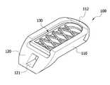
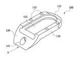
도 2는 본 발명의 일 실시예에 따른 추간공 확장기의 사시도를 나타낸다.
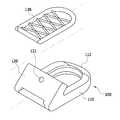
도 3은 본 발명의 일 실시예에 따른 추간공 확장기의 분해 사시도를 나타낸다.
도 4는 본 발명의 일 실시예에 따른 추간공 확장기의 측면도를 나타낸다.
도 5는 본 발명의 일 실시예에 따른 추간공 확장기의 평면도를 나타낸다.
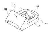
도 6은 본 발명의 일 실시예에 따른 추간공 확장기의 사시도를 나타낸다.
도 7은 본 발명의 일 실시예에 따른 추간공 확장기의 측면도를 나타낸다.
도 8은 본 발명의 일 실시예에 따른 추간공 확장기의 분해 사시도를 나타낸다.
도 9는 본 발명의 일 실시예에 따른 추간공 확장기의 평면도를 나타낸다.
도 10은 본 발명의 일 실시예에 따른 추간공 확장기의 사시도를 나타낸다.
도 11은 본 발명의 일 실시예에 따른 추간공 확장기의 사시도를 나타낸다.
도 12는 본 발명의 일 실시예에 따른 추간공 확장기의 사시도를 나타낸다.
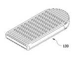
도 13은 본 발명의 일 실시예에 따른 메시부의 사시도를 나타낸다.
도 14는 본 발명의 일 실시예에 따른 메시부의 사시도를 나타낸다.
도 15는 본 발명의 일 실시예에 따른 메시부의 사시도를 나타낸다.
도 16은 본 발명의 일 실시예에 따른 메시부의 사시도를 나타낸다.
도 17은 본 발명의 일 실시예에 따른 추간공 확장기 삽입장치의 사시도를 나타낸다.
도 18은 본 발명의 일 실시예에 따른 추간공 확장기 삽입장치의 측면도를 나타낸다.
도 19는 본 발명의 일 실시예에 따른 추간공 확장기 삽입장치의 부분확대도를 나타낸다.
도 20은 본 발명의 일 실시예에 따른 추간공 확장기 삽입장치의 분해 사시도를 나타낸다.
도 21은 본 발명의 일 실시예에 따른 추간공 확장기 삽입장치의 부분확대된 사시도를 나타낸다.
도 22는 본 발명의 일 실시예에 따른 추간공 삽입기구의 부분확대된 측면도를 나타낸다.
도 23은 도 22를 정면에서 바라본 도면을 나타낸다.
도 24는 본 발명의 일 실시예에 따른 추간공 확장기의 사시도를 나타낸다.
도 25는 본 발명의 일 실시예에 따른 추간공 확장기의 사시도를 나타낸다.
도 26은 도 24 및 도 25를 V방향에서 바라본 도면을 나타낸다.
도 27은 본 발명의 일 실시예에 따른 추간공 확장기의 사시도를 나타낸다.
도 28은 도 27을 V방향에서 바라본 도면을 나타낸다.
도 29는 본 발명의 일 실시예에 따른 추간공 확장기의 사시도를 나타낸다.
도 30은 도 29를 V방향에서 바라본 도면을 나타낸다.Figure 1 shows a conceptual diagram applying the intervertebral dilator according to an embodiment of the present invention to the back joint.
Figure 2 shows a perspective view of the intervertebral dilator according to an embodiment of the present invention.
Figure 3 shows an exploded perspective view of the intervertebral dilator in accordance with an embodiment of the present invention.
Figure 4 shows a side view of the intervertebral dilator in accordance with an embodiment of the present invention.
Figure 5 shows a plan view of the intervertebral dilator according to an embodiment of the present invention.
Figure 6 shows a perspective view of the intervertebral dilator according to an embodiment of the present invention.
Figure 7 shows a side view of the intervertebral dilator in accordance with an embodiment of the present invention.
8 is an exploded perspective view of the intervertebral dilator according to an embodiment of the present invention.
Figure 9 shows a plan view of the intervertebral dilator in accordance with an embodiment of the present invention.
Figure 10 shows a perspective view of the intervertebral dilator according to an embodiment of the present invention.
Figure 11 shows a perspective view of the intervertebral dilator according to an embodiment of the present invention.
12 is a perspective view of the intervertebral dilator in accordance with an embodiment of the present invention.
13 is a perspective view of a mesh unit according to an embodiment of the present invention.
14 is a perspective view of a mesh unit according to an embodiment of the present invention.
15 is a perspective view of a mesh unit according to an embodiment of the present invention.
16 is a perspective view of a mesh unit according to an embodiment of the present invention.
Figure 17 shows a perspective view of the intervertebral dilator insertion device according to an embodiment of the present invention.
18 is a side view of the intervertebral dilator insertion device according to an embodiment of the present invention.
19 is a partially enlarged view of the intervertebral dilator insertion apparatus according to the embodiment of the present invention.
20 is an exploded perspective view of the intervertebral dilator insertion apparatus according to an embodiment of the present invention.
Figure 21 shows a partially enlarged perspective view of the intervertebral dilator insertion device according to an embodiment of the present invention.
Figure 22 shows a partially enlarged side view of the intervertebral hole insertion mechanism according to an embodiment of the present invention.
FIG. 23 shows the front view of FIG. 22.
24 is a perspective view of the intervertebral dilator in accordance with an embodiment of the present invention.
25 is a perspective view of the intervertebral dilator in accordance with an embodiment of the present invention.
FIG. 26 is a view of FIGS. 24 and 25 as viewed in the V direction.
27 is a perspective view of the intervertebral dilator in accordance with an embodiment of the present invention.
FIG. 28 is a view of FIG. 27 viewed in the V direction.
29 is a perspective view of the intervertebral dilator in accordance with an embodiment of the present invention.
FIG. 30 is a view of FIG. 29 viewed in the V direction.
이하, 첨부된 도면들을 참조하여 본 발명에 따른 실시예를 상세히 설명한다. 이 과정에서 도면에 도시된 구성요소의 크기나 형상 등은 설명의 명료성과 편의상 과장되게 도시될 수 있다. 또한, 본 발명의 구성 및 작용을 고려하여 특별히 정의된 용어들은 사용자, 운용자의 의도 또는 관례에 따라 달라질 수 있다. 이러한 용어들에 대한 정의는 본 명세서 전반에 걸친 내용을 토대로 내려져야 한다.Hereinafter, embodiments of the present invention will be described in detail with reference to the accompanying drawings. The sizes and shapes of the components shown in the drawings may be exaggerated for clarity and convenience. In addition, terms defined in consideration of the configuration and operation of the present invention may be changed according to the intention or custom of the user, the operator. Definitions of these terms should be based on the content of this specification.
그리고, 본 발명의 사상은 제시되는 실시예에 제한되지 아니하고 본 발명의 사상을 이해하는 당업자는 동일한 사상의 범위내에서 다른 실시예를 용이하게 실시할 수 있을 것이나, 이 또한 본 발명의 범위 내에 속함은 물론이다.
In addition, the spirit of the present invention is not limited to the embodiments presented, and those skilled in the art who understand the spirit of the present invention may easily implement other embodiments within the scope of the same idea, but this also falls within the scope of the present invention. Of course.
도 1 내지 도 30은 본 발명에 따른 추간공 확장기(100) 및 추간공 확장기 삽입장치(300)를 나타내는 도면으로써 함께 설명한다.
1 to 30 illustrate the
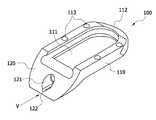
본 발명의 실시예에 따른 추간공 확장기(100)는 후관절에 삽입을 위한 구조물로, 좁아진 추간공의 공간을 복원하고, 몸의 하중을 지지하도록 구성되며, 삽입부(110), 고정부(120) 및 메쉬부(130)를 포함하여 구성된다.
도 1 에 도시된 바와 같이 삽입부(110)는 인접한 두 개의 척추 뼈마디 사이에 삽입되어 상기 척추 뼈 간의 일정 공간이 유지되기 위한 일정 두께를 가지며, 일측에는 팁부(112)를 포함하고, 타측은 고정부(120)와 연결되어 있다.As shown in FIG. 1, the
이때, 상기 두 개의 척추 뼈마디 사이는 두 개의 척추체 사이의 후관절을 의미하며, 보다 구체적으로 상기 두 개의 척추체란 제1척추체(101) 및 제2척추체(102)를 의미한다.
At this time, between the two vertebral bone nodes means a posterior joint between two vertebral bodies, and more specifically, the two vertebral bodies mean the first and second
본 발명의 팁부(112)는 “U”자 형태로 만곡되어 있으며, 삽입되기 용이하도록 얇게 형성된 것을 특징으로 한다. 보다 구체적으로 팁부(112)는 상기 팁부(112)를 제외한 삽입부(110)의 두께보다 얇게 형성될 수 있다.
또한 본 발명의 삽입부(110)의 두께는 후관절의 형상에 따라 설정 가능할 수 있다. 구체적으로, 삽입부(110)의 두께는 다양한 볼록도를 고려하여, 이식하고자 하는 환자의 체형 구조에 보다 적합하게 제공될 수 있는 것으로 삽입부의 두께가 변화할 수 있으며, 이는 어느 한 형태에 한정하지 않는다.
In addition, the thickness of the
본 발명의 고정부(120)는 삽입부(110) 타측과 연결되어 있으며 두개의 척추체 측면 중 적어도 어느 하나의 척추체 측면에 위치할 수 있다. 보다 구체적으로 도 2 내지 도 5 에서의 추간공 확장기(100)는 제2척추체(102) 측면에 고정부(120)가 위치하게 될 때의 일 실시예를 나타낸 도면이고, 도 6 내지 도 9 에서의 추간공 확장기(100)는 제1척추체(101) 측면에 고정부(120)가 위치하게 될 때의 일 실시예를 나타낸 도면이다.The fixing
또한 본 발명의 삽입부(110) 및 고정부(120)는 일정 각도(θ)만큼 기울여 후관절면의 뒷면에 밀착되도록 한다. 보다 구체적으로 삽입부(110) 및 고정부(120)가 이루는 각도(θ)는 후관절 및 척추체 측면이 이루는 각도와 실질적으로 동일한 것을 특징으로 한다.In addition, the
일정 각도(θ)는 후관절과 척추체 측면이 이루는 각도를 의미하는 것으로써 수술전 환자의 CT영상을 이용하여 각도를 측정한 후 설계에 반영하는 것이 바람직하다.The predetermined angle θ means the angle formed by the posterior joint and the vertebral body, and it is preferable to measure the angle using a CT image of the patient before surgery and reflect the angle in the design.
보다 구체적으로, 도 4에 도시된 바와 같이 고정부(120)가 하향으로 고정될 때는 110° 내지 150°일 수 있으며, 도 7에 도시된 바와 같이 고정부(120)가 상향으로 고정될 때는 20° 내지 60일 수 있다.More specifically, as shown in FIG. 4, when the fixing
또한 고정부(120)가 하향으로 고정될 때는 연령, 성별에 관계없이 경추 아랫쪽으로 갈수록 각도가 작아질 수 있다.
In addition, when the fixing
고정부(120)는 본 발명의 추간공 확장기(100)를 후관절에 보다 안전하고 정확하게 체결하기 위한 수단이다. 보다 바람직하게 고정부(120)는 척추체 측면에 고정하기 위한 고정나사를 적어도 하나를 포함할 수 있으며, 상기 고정나사를 수용할 수 있는 적어도 하나의 홀(121)을 포함할 수 있다.
The fixing
또한 본 발명의 삽입부(110)는 개구부(111)를 포함하는 것을 특징으로 한다. 여기서, 개구부(111)라 함은 뼈의 성장을 허용하는 공간을 의미하며, 골대체재와 인접하는 뼈와의 접촉면을 증가시켜 보다 안정된 상태를 유지할 수 있고, 골유합이 빠르게 진행될 수 있도록 한다.
In addition, the
또한 본 발명의 삽입부(110)는 적어도 일부에 방사선 비투과 물질을 포함할 수 있다. 상기 방사선 비투과 물질이라 함은 추간공 확장기(100)의 위치확인을 하기 위한 수단으로써, 삽입부(110)의 팁부(112) 또는 개구부(111)에 포함될 수 있다.
In addition, the
한편, 인접하는 척추 뼈와 닿는 추간공 확장기(100)의 상면 또는 하면의 표면은 인접하는 척추 뼈 사이에 이식된 상태에서 이탈을 방지하고 최초 삽입 위치의 변화를 최소화시키도록 일정 이상으로 거친 표면을 갖도록 구성될 수 있다. 도 10 에서와 같이 인접하는 척추 뼈와 닿는 추간공 확장기(100)의 상면에 돌기(113)가 형성될 수 있고, 도 11 및 도 12 에서와 같이 요철(114)을 형성할 수 있다. 특히 삽입은 가능하나 빠지지 않게 하기 위해서 도 11 에서 보는 바와 같이 앞쪽 경사면이 길고, 뒤쪽은 짧은 래칫 형태의 요철(114)을 형성할 수 있으며, 이는 어느 한 형태에 한정하지 않는다.
On the other hand, the surface of the upper or lower surface of the
또한, 본 발명의 실시예에 따른 추간공 확장기(100)는 인체에 무해하며 소정의 탄성을 가지는 PEEK(polyetheretherketone)재질 또는 티타늄 등으로 구성될 수 있으며, 이 밖에도 탄타늄, 형상기억합금, 스테인리스 스틸 및 플라스틱 등과 같이 본 발명의 추간공 확장기(100)로 용이한 재질이라면 이용 가능하다.
In addition, the
다음으로 본 발명은 메쉬부(130)를 포함하는 것을 특징으로 한다. 보다 구체적으로, 본 발명의 메쉬부(130)는 골 대체재를 함침하여 본 발명의 개구부(111)에 삽입될 수 있다. 일 예로 메쉬부(130)가 개구부(111)에 삽일될 때 슬라이드 삽입될 수 있다. 상기 메쉬부(130)는 그물망 형태를 하고 있는 것으로써, 골대체제 또는 골유합제를 안전하고 효과적으로 유지시키기 위한 형태라면 그물망 형태, 그물 바구니 형태, 이중 구조의 그물망 형태일 수 있으며, 특별히 제한되지 않으며 도 13 내지 도 16에서 와 같이 어떠한 형태든지 가능하다.Next, the present invention is characterized by including a
메쉬부(130)에 함침되어 있는 골대체재로 인하여 척추 뼈와 접촉면을 증가시켜 골유합이 빠르게 진행될 수 있다.Due to the bone structure impregnated in the
여기서 골 대체재의 일 예로는 DBM(Demineralized bone matrix)을 사용하였다. 이는 표면에 존재하는 미네랄을 화학적 처리로 제거한 이식재로서, 골전도능력 및 골유도능력을 지닌 치료용 이식재를 의미한다.Here, as an example of the bone substitute material was used DBM (Demineralized bone matrix). This is a graft material from which the minerals present on the surface are removed by chemical treatment, and refers to a therapeutic implant having a bone conduction ability and a bone inducing ability.
또한, 본 발명의 실시예에 따른 메쉬부(130)는 인체에 무해하며 소정의 탄성을 가지는 PEEK(polyetheretherketone)재질 또는 티타늄 등으로 구성될 수 있으며, 이 밖에도 탄타늄, 형상기억합금, 스테인리스 스틸 및 플라스틱 등과 같이 본 발명의 추간공 확장기(100)로 용이한 재질이라면 이용 가능하다.
In addition, the
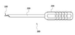
또한 본 발명은 추간공 확장기(100)를 후관절에 삽입하기 위한 삽입기구(200)를 포함하는 추간공 확장기 삽입장치(300)에 관한 발명이다.In addition, the present invention relates to an intervertebral
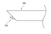
도 17 내지 도 23을 참조하면, 길이방향으로 확장되어 있어 일측에는 추간공 확장기(100)를 수용하기 위한 가이드부(210)를 포함하고 타측에는 그립부(220)를 포함한다. 특히, 상기 가이드부(210)는 고정부(120)의 홀(121)에 연결되는 가이드 돌기(211)를 포함하고, 가이드부(210) 및 가이드 돌기(211)는 고정부(120)와 평행하도록 구성되어 있으며, 실질적으로 가이드부(210) 및 가이드 돌기(211)의 일면은 상기 고정부(120)와 동일한 경사면을 이루는 것을 특징으로 한다.
17 to 23, it extends in the longitudinal direction and includes a
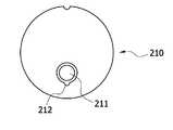
또한 본 발명의 가이드부(210)는 회전방지 수단(212)을 더 포함 할 수 있다. 도 24, 도 25는 본 발명의 일 실시예에 따른 추간공 확장기(100) 사시도, 도 26은 도 24, 도 25를 V방향에서 바라본 도면, 27은 본 발명의 일 실시예에 따른 추간공 확장기(100)의 사시도, 도 28은 도 27을 V방향에서 바라본 도면, 29는 본 발명의 일 실시예에 따른 추간공 확장기(100)의 사시도, 도 30는 도 29를 V방향에서 바라본 도면을 나타낸다.In addition, the
회전방지 수단(212)은 상기 도 24 내지 도 30과 같이 고정부(120)의 가이드 홈(122)의 모양에 따라서 달라 질 수 있으며, 어느 하나에 한정하는 것은 아니다.
The rotation preventing means 212 may vary depending on the shape of the
그리고 본 발명에 따른 추간공 확장기(100)는 전방(A) 및 후방(P)의 두께와 다양한 볼록도를 고려하여, 이식하고자 하는 환자의 체형 구조에 보다 적합하게 제공하는 것이 바람직하며, 사출성형, 열간성형 및 열간가압성형 등을 이용하여 용이하게 생산해내는 것이 가능하다.
And in consideration of the thickness of the front (A) and rear (P) and various convexities, the
상기의 실시예는 본 발명의 내용을 예시하는 것일 뿐 본 발명의 범위가 상기 실시예에 한정되는 것은 아니다. 본 발명의 실시예는 당업계에서 평균적인 지식을 가진 자에게 본 발명을 보다 완전하게 설명하기 위해 제공되는 것이다.The above embodiments are merely illustrative of the contents of the present invention, but the scope of the present invention is not limited to the above embodiments. Embodiments of the present invention are provided to more fully describe the present invention to those skilled in the art.
100: 추간공 확장기
101: 제1척추체 102: 제2척추체
110: 삽입부 111: 개구부
112: 팁부 113: 돌기
114: 요철 120: 고정부
121: 홀 122: 가이드 홈
130: 메쉬부
200: 삽입기구
210: 가이드부 211: 가이드 돌기
212: 회전방지 수단 220: 그립부
300: 추간공 확장기 삽입장치100: intervertebral dilator
101: first vertebral body 102: second vertebral body
110: insertion portion 111: opening
112: tip 113: projection
114: unevenness 120: fixing part
121: hole 122: guide groove
130: mesh portion
200: insertion mechanism
210: guide portion 211: guide projection
212: anti-rotation means 220: grip portion
300: intervertebral expander insertion device
Claims (12)
Translated fromKorean개구부가 형성되며, 일측에 팁부를 포함하여 상기 후관절에 삽입되는 삽입부;
상기 삽입부 타측으로부터 연결되어 상기 두개의 척추체 중 적어도 어느 하나의 척추체 측면에 고정되는 고정부; 및
상기 개구부에 삽입되는 골 대체재가 함침된 메쉬부; 를 포함하는 추간공 확장기.
In cervical intervertebral dilator for insertion into the posterior joint between two vertebral bodies,
An opening part is formed and an insertion part inserted into the posterior joint including a tip part at one side;
A fixing part connected to the insertion part from the other side and fixed to at least one side of the vertebral body of the two vertebral bodies; And
A mesh part impregnated with a bone substitute inserted into the opening; Intervertebral dilator comprising.
상기 팁부는 만곡되어 있으며, 상기 팁부를 제외한 삽입부의 두께보다 얇게 형성된 것을 특징으로 하는 추간공 확장기.
The method of claim 1,
The tip portion is curved, intervertebral dilator, characterized in that formed thinner than the thickness of the insertion portion except the tip portion.
상기 삽입부의 두께는 후관절의 형상에 따라 설정 가능한 것을 특징으로 하는 추간공 확장기.The method of claim 1,
Intercalator dilator, characterized in that the thickness of the insert can be set according to the shape of the posterior joint.
상기 삽입부 및 고정부가 이루는 각도(θ)는 후관절 및 척추체 측면이 이루는 각도와 동일한 것을 특징으로 하는 추간공 확장기.
The method of claim 1,
The inter-hole expander, characterized in that the angle formed by the insertion portion and the fixing portion (θ) is the same as the angle formed by the side of the back joint and vertebral body.
상기 각도(θ)는 고정부가 하향으로 고정될 때 110° 내지 150°인 것을 특징으로 하는 추간공 확장기.
5. The method of claim 4,
The angle (θ) is intervertebral dilator, characterized in that 110 ° to 150 ° when the fixing portion is fixed downward.
상기 각도(θ)는 고정부가 상향으로 고정될 때 20° 내지 60°인 것을 특징으로 하는 추간공 확장기.
5. The method of claim 4,
The angle (θ) is intervertebral dilator, characterized in that 20 to 60 ° when the fixing portion is fixed upward.
상기 삽입부는 방사선 비투과 물질을 포함하는 것을 특징으로 하는 추간공 확장기.
The method of claim 1,
And the insertion portion comprises a radiopaque material.
상기 고정부는 후관절면에 고정나사를 수용할 수 있는 적어도 하나의 홀을 포함하는 것을 특징으로 하는 추간공 확장기.
The method of claim 1,
The fixing unit intervertebral dilator, characterized in that it comprises at least one hole for receiving a fixing screw in the facet joint.
An intervertebral dilator inserting apparatus, comprising: an insertion mechanism for inserting the intervertebral dilator according to any one of claims 1 to 8 into the posterior joint, wherein the insertion mechanism includes a guide portion for accommodating the intervertebral dilator on one side.
상기 삽입기구는 길이방향으로 확장되어 타측에는 그립부를 포함하는 추간공 확장기 삽입장치.
10. The method of claim 9,
The insertion mechanism extends in the longitudinal direction intervertebral ball expander insertion device comprising a grip portion on the other side.
상기 가이드부의 일면은 추간공 확장기의 고정부의 일면과 동일한 경사면을 이루며, 고정부의 홀에 연결되는 가이드 돌기를 포함하는 추간공 확장기 삽입장치.
10. The method of claim 9,
One side of the guide portion is intervertebral dilator inserting device comprising a guide protrusion connected to the hole of the fixing portion forming the same inclined surface and one surface of the fixing portion of the intervertebral hole expander.
상기 가이드부의 일면은 추간공 확장기의 고정부의 일면과 동일한 경사면을 이루며, 회전방지 수단을 더 포함하는 것을 특징으로 하는 추간공 확장기 삽입장치.10. The method of claim 9,
One surface of the guide portion forms the same inclined surface as one surface of the fixing portion of the intervertebral dilator, intervertebral ball expander insertion device, characterized in that it further comprises a rotation preventing means.
Priority Applications (2)
| Application Number | Priority Date | Filing Date | Title |
|---|---|---|---|
| KR1020120100617AKR101365843B1 (en) | 2012-09-11 | 2012-09-11 | Apparatus for cervical foraminal distraction |
| PCT/KR2013/008039WO2014042388A2 (en) | 2012-09-11 | 2013-09-05 | Cervical foraminal expander |
Applications Claiming Priority (1)
| Application Number | Priority Date | Filing Date | Title |
|---|---|---|---|
| KR1020120100617AKR101365843B1 (en) | 2012-09-11 | 2012-09-11 | Apparatus for cervical foraminal distraction |
Publications (1)
| Publication Number | Publication Date |
|---|---|
| KR101365843B1true KR101365843B1 (en) | 2014-02-24 |
Family
ID=50271643
Family Applications (1)
| Application Number | Title | Priority Date | Filing Date |
|---|---|---|---|
| KR1020120100617AActiveKR101365843B1 (en) | 2012-09-11 | 2012-09-11 | Apparatus for cervical foraminal distraction |
Country Status (2)
| Country | Link |
|---|---|
| KR (1) | KR101365843B1 (en) |
| WO (1) | WO2014042388A2 (en) |
Cited By (1)
| Publication number | Priority date | Publication date | Assignee | Title |
|---|---|---|---|---|
| WO2024029645A1 (en)* | 2022-08-04 | 2024-02-08 | 주식회사 에이스메디코프 | Spinal fusion cage having porous structure |
Families Citing this family (1)
| Publication number | Priority date | Publication date | Assignee | Title |
|---|---|---|---|---|
| EP3727174B1 (en)* | 2017-12-18 | 2022-01-26 | G & G S.r.l. | Improved partial endoprosthesis device for a vertebral joint |
Citations (4)
| Publication number | Priority date | Publication date | Assignee | Title |
|---|---|---|---|---|
| US20030105527A1 (en) | 2001-12-03 | 2003-06-05 | Surgical Dynamics, Inc. | Apparatus for fusing adjacent bone structures |
| US20030125739A1 (en) | 2001-12-12 | 2003-07-03 | Bagga Charanpreet S. | Bioactive spinal implants and method of manufacture thereof |
| US20030139812A1 (en) | 2001-11-09 | 2003-07-24 | Javier Garcia | Spinal implant |
| US6648917B2 (en) | 2001-10-17 | 2003-11-18 | Medicinelodge, Inc. | Adjustable bone fusion implant and method |
- 2012
- 2012-09-11KRKR1020120100617Apatent/KR101365843B1/enactiveActive
- 2013
- 2013-09-05WOPCT/KR2013/008039patent/WO2014042388A2/enactiveApplication Filing
Patent Citations (4)
| Publication number | Priority date | Publication date | Assignee | Title |
|---|---|---|---|---|
| US6648917B2 (en) | 2001-10-17 | 2003-11-18 | Medicinelodge, Inc. | Adjustable bone fusion implant and method |
| US20030139812A1 (en) | 2001-11-09 | 2003-07-24 | Javier Garcia | Spinal implant |
| US20030105527A1 (en) | 2001-12-03 | 2003-06-05 | Surgical Dynamics, Inc. | Apparatus for fusing adjacent bone structures |
| US20030125739A1 (en) | 2001-12-12 | 2003-07-03 | Bagga Charanpreet S. | Bioactive spinal implants and method of manufacture thereof |
Cited By (1)
| Publication number | Priority date | Publication date | Assignee | Title |
|---|---|---|---|---|
| WO2024029645A1 (en)* | 2022-08-04 | 2024-02-08 | 주식회사 에이스메디코프 | Spinal fusion cage having porous structure |
Also Published As
| Publication number | Publication date |
|---|---|
| WO2014042388A2 (en) | 2014-03-20 |
| WO2014042388A3 (en) | 2014-05-08 |
Similar Documents
| Publication | Publication Date | Title |
|---|---|---|
| US11896493B2 (en) | Expandable intervertebral spacer | |
| KR101877731B1 (en) | Cage for disc space between vertebrae | |
| AU2002322960B2 (en) | Intervertebral implant comprising a three-part articulation | |
| US8845727B2 (en) | Intervertebral body fusion implant device | |
| US9198774B2 (en) | Intervertebral disk cage and stabilizer | |
| CN102462562B (en) | Intervertebral cage having flexibility | |
| US20160166295A1 (en) | Orthopedic devices with a locking mechanism | |
| US20180256363A1 (en) | Cage for disc space between vertebrae | |
| US20080021466A1 (en) | Spine treatment devices and methods | |
| TW200422033A (en) | Intervertebral implant | |
| JP2016512110A (en) | Independent intervertebral implant between vertebral bodies | |
| US9456904B2 (en) | Facet fixation device | |
| JP2014533178A (en) | Intervertebral spinal implant | |
| KR20040091735A (en) | Dynamic intervertebral implant | |
| KR20110060916A (en) | Implants with Spiral Anchors | |
| JP2008534127A (en) | Intervertebral device for stabilizing the spinal column and method of implanting the device | |
| CN103610523A (en) | Minimally invasive lateral approach interbody fusion device | |
| CN203662946U (en) | Minimally invasive lateral approach interbody fusion cage | |
| CN103610522A (en) | Lumbar vertebra posterior approach fusion device | |
| CN105030388A (en) | Lumbar intervertebral disc prosthesis, implanting instrument, device composed of waist prosthesis and implanting instrument and method for inserting lumbar vertebra implantation material | |
| US8246653B2 (en) | Device for the lateral stabilization of the spine | |
| KR101502061B1 (en) | Expandable fusion cage | |
| CN203609549U (en) | Posterior lumbar fusion cage | |
| KR101365843B1 (en) | Apparatus for cervical foraminal distraction | |
| CN204468350U (en) | Invasive lumbar fusion device |
Legal Events
| Date | Code | Title | Description |
|---|---|---|---|
| PA0109 | Patent application | Patent event code:PA01091R01D Comment text:Patent Application Patent event date:20120911 | |
| A201 | Request for examination | ||
| PA0201 | Request for examination | Patent event code:PA02012R01D Patent event date:20120919 Comment text:Request for Examination of Application Patent event code:PA02011R01I Patent event date:20120911 Comment text:Patent Application | |
| E902 | Notification of reason for refusal | ||
| PE0902 | Notice of grounds for rejection | Comment text:Notification of reason for refusal Patent event date:20131129 Patent event code:PE09021S01D | |
| E701 | Decision to grant or registration of patent right | ||
| PE0701 | Decision of registration | Patent event code:PE07011S01D Comment text:Decision to Grant Registration Patent event date:20140211 | |
| GRNT | Written decision to grant | ||
| PR0701 | Registration of establishment | Comment text:Registration of Establishment Patent event date:20140214 Patent event code:PR07011E01D | |
| PR1002 | Payment of registration fee | Payment date:20140214 End annual number:3 Start annual number:1 | |
| PG1601 | Publication of registration | ||
| FPAY | Annual fee payment | Payment date:20170214 Year of fee payment:4 | |
| PR1001 | Payment of annual fee | Payment date:20170214 Start annual number:4 End annual number:4 | |
| FPAY | Annual fee payment | Payment date:20190215 Year of fee payment:6 | |
| PR1001 | Payment of annual fee | Payment date:20190215 Start annual number:6 End annual number:6 | |
| PR1001 | Payment of annual fee | Payment date:20210120 Start annual number:8 End annual number:8 | |
| PR1001 | Payment of annual fee | Payment date:20220113 Start annual number:9 End annual number:9 | |
| PR1001 | Payment of annual fee | Payment date:20221213 Start annual number:10 End annual number:10 | |
| PR1001 | Payment of annual fee | Payment date:20231212 Start annual number:11 End annual number:11 | |
| PR1001 | Payment of annual fee | Payment date:20250212 Start annual number:12 End annual number:12 |