KR101365548B1 - Fracture-resistant helical stent incorporating bistable cells and methods of use - Google Patents
Fracture-resistant helical stent incorporating bistable cells and methods of useDownload PDFInfo
- Publication number
- KR101365548B1 KR101365548B1KR1020087026197AKR20087026197AKR101365548B1KR 101365548 B1KR101365548 B1KR 101365548B1KR 1020087026197 AKR1020087026197 AKR 1020087026197AKR 20087026197 AKR20087026197 AKR 20087026197AKR 101365548 B1KR101365548 B1KR 101365548B1
- Authority
- KR
- South Korea
- Prior art keywords
- prosthesis
- strut
- unit cell
- distal end
- bistable
- Prior art date
- Legal status (The legal status is an assumption and is not a legal conclusion. Google has not performed a legal analysis and makes no representation as to the accuracy of the status listed.)
- Expired - Fee Related
Links
Images


Classifications
- A—HUMAN NECESSITIES
- A61—MEDICAL OR VETERINARY SCIENCE; HYGIENE
- A61F—FILTERS IMPLANTABLE INTO BLOOD VESSELS; PROSTHESES; DEVICES PROVIDING PATENCY TO, OR PREVENTING COLLAPSING OF, TUBULAR STRUCTURES OF THE BODY, e.g. STENTS; ORTHOPAEDIC, NURSING OR CONTRACEPTIVE DEVICES; FOMENTATION; TREATMENT OR PROTECTION OF EYES OR EARS; BANDAGES, DRESSINGS OR ABSORBENT PADS; FIRST-AID KITS
- A61F2/00—Filters implantable into blood vessels; Prostheses, i.e. artificial substitutes or replacements for parts of the body; Appliances for connecting them with the body; Devices providing patency to, or preventing collapsing of, tubular structures of the body, e.g. stents
- A61F2/02—Prostheses implantable into the body
- A61F2/04—Hollow or tubular parts of organs, e.g. bladders, tracheae, bronchi or bile ducts
- A61F2/06—Blood vessels
- A61F2/07—Stent-grafts
- A—HUMAN NECESSITIES
- A61—MEDICAL OR VETERINARY SCIENCE; HYGIENE
- A61F—FILTERS IMPLANTABLE INTO BLOOD VESSELS; PROSTHESES; DEVICES PROVIDING PATENCY TO, OR PREVENTING COLLAPSING OF, TUBULAR STRUCTURES OF THE BODY, e.g. STENTS; ORTHOPAEDIC, NURSING OR CONTRACEPTIVE DEVICES; FOMENTATION; TREATMENT OR PROTECTION OF EYES OR EARS; BANDAGES, DRESSINGS OR ABSORBENT PADS; FIRST-AID KITS
- A61F2/00—Filters implantable into blood vessels; Prostheses, i.e. artificial substitutes or replacements for parts of the body; Appliances for connecting them with the body; Devices providing patency to, or preventing collapsing of, tubular structures of the body, e.g. stents
- A61F2/82—Devices providing patency to, or preventing collapsing of, tubular structures of the body, e.g. stents
- A61F2/86—Stents in a form characterised by the wire-like elements; Stents in the form characterised by a net-like or mesh-like structure
- A61F2/88—Stents in a form characterised by the wire-like elements; Stents in the form characterised by a net-like or mesh-like structure the wire-like elements formed as helical or spiral coils
- A—HUMAN NECESSITIES
- A61—MEDICAL OR VETERINARY SCIENCE; HYGIENE
- A61B—DIAGNOSIS; SURGERY; IDENTIFICATION
- A61B17/00—Surgical instruments, devices or methods
- A61B17/11—Surgical instruments, devices or methods for performing anastomosis; Buttons for anastomosis
- A—HUMAN NECESSITIES
- A61—MEDICAL OR VETERINARY SCIENCE; HYGIENE
- A61F—FILTERS IMPLANTABLE INTO BLOOD VESSELS; PROSTHESES; DEVICES PROVIDING PATENCY TO, OR PREVENTING COLLAPSING OF, TUBULAR STRUCTURES OF THE BODY, e.g. STENTS; ORTHOPAEDIC, NURSING OR CONTRACEPTIVE DEVICES; FOMENTATION; TREATMENT OR PROTECTION OF EYES OR EARS; BANDAGES, DRESSINGS OR ABSORBENT PADS; FIRST-AID KITS
- A61F2/00—Filters implantable into blood vessels; Prostheses, i.e. artificial substitutes or replacements for parts of the body; Appliances for connecting them with the body; Devices providing patency to, or preventing collapsing of, tubular structures of the body, e.g. stents
- A61F2/02—Prostheses implantable into the body
- A61F2/04—Hollow or tubular parts of organs, e.g. bladders, tracheae, bronchi or bile ducts
- A61F2/06—Blood vessels
- A61F2/064—Blood vessels with special features to facilitate anastomotic coupling
- A—HUMAN NECESSITIES
- A61—MEDICAL OR VETERINARY SCIENCE; HYGIENE
- A61F—FILTERS IMPLANTABLE INTO BLOOD VESSELS; PROSTHESES; DEVICES PROVIDING PATENCY TO, OR PREVENTING COLLAPSING OF, TUBULAR STRUCTURES OF THE BODY, e.g. STENTS; ORTHOPAEDIC, NURSING OR CONTRACEPTIVE DEVICES; FOMENTATION; TREATMENT OR PROTECTION OF EYES OR EARS; BANDAGES, DRESSINGS OR ABSORBENT PADS; FIRST-AID KITS
- A61F2/00—Filters implantable into blood vessels; Prostheses, i.e. artificial substitutes or replacements for parts of the body; Appliances for connecting them with the body; Devices providing patency to, or preventing collapsing of, tubular structures of the body, e.g. stents
- A61F2/82—Devices providing patency to, or preventing collapsing of, tubular structures of the body, e.g. stents
- A61F2/86—Stents in a form characterised by the wire-like elements; Stents in the form characterised by a net-like or mesh-like structure
- A61F2/90—Stents in a form characterised by the wire-like elements; Stents in the form characterised by a net-like or mesh-like structure characterised by a net-like or mesh-like structure
- A61F2/91—Stents in a form characterised by the wire-like elements; Stents in the form characterised by a net-like or mesh-like structure characterised by a net-like or mesh-like structure made from perforated sheets or tubes, e.g. perforated by laser cuts or etched holes
- A61F2/915—Stents in a form characterised by the wire-like elements; Stents in the form characterised by a net-like or mesh-like structure characterised by a net-like or mesh-like structure made from perforated sheets or tubes, e.g. perforated by laser cuts or etched holes with bands having a meander structure, adjacent bands being connected to each other
- A—HUMAN NECESSITIES
- A61—MEDICAL OR VETERINARY SCIENCE; HYGIENE
- A61L—METHODS OR APPARATUS FOR STERILISING MATERIALS OR OBJECTS IN GENERAL; DISINFECTION, STERILISATION OR DEODORISATION OF AIR; CHEMICAL ASPECTS OF BANDAGES, DRESSINGS, ABSORBENT PADS OR SURGICAL ARTICLES; MATERIALS FOR BANDAGES, DRESSINGS, ABSORBENT PADS OR SURGICAL ARTICLES
- A61L27/00—Materials for grafts or prostheses or for coating grafts or prostheses
- A61L27/02—Inorganic materials
- A61L27/04—Metals or alloys
- A—HUMAN NECESSITIES
- A61—MEDICAL OR VETERINARY SCIENCE; HYGIENE
- A61M—DEVICES FOR INTRODUCING MEDIA INTO, OR ONTO, THE BODY; DEVICES FOR TRANSDUCING BODY MEDIA OR FOR TAKING MEDIA FROM THE BODY; DEVICES FOR PRODUCING OR ENDING SLEEP OR STUPOR
- A61M25/00—Catheters; Hollow probes
- A61M25/01—Introducing, guiding, advancing, emplacing or holding catheters
- A—HUMAN NECESSITIES
- A61—MEDICAL OR VETERINARY SCIENCE; HYGIENE
- A61F—FILTERS IMPLANTABLE INTO BLOOD VESSELS; PROSTHESES; DEVICES PROVIDING PATENCY TO, OR PREVENTING COLLAPSING OF, TUBULAR STRUCTURES OF THE BODY, e.g. STENTS; ORTHOPAEDIC, NURSING OR CONTRACEPTIVE DEVICES; FOMENTATION; TREATMENT OR PROTECTION OF EYES OR EARS; BANDAGES, DRESSINGS OR ABSORBENT PADS; FIRST-AID KITS
- A61F2/00—Filters implantable into blood vessels; Prostheses, i.e. artificial substitutes or replacements for parts of the body; Appliances for connecting them with the body; Devices providing patency to, or preventing collapsing of, tubular structures of the body, e.g. stents
- A61F2/82—Devices providing patency to, or preventing collapsing of, tubular structures of the body, e.g. stents
- A61F2/86—Stents in a form characterised by the wire-like elements; Stents in the form characterised by a net-like or mesh-like structure
- A61F2/90—Stents in a form characterised by the wire-like elements; Stents in the form characterised by a net-like or mesh-like structure characterised by a net-like or mesh-like structure
- A61F2/91—Stents in a form characterised by the wire-like elements; Stents in the form characterised by a net-like or mesh-like structure characterised by a net-like or mesh-like structure made from perforated sheets or tubes, e.g. perforated by laser cuts or etched holes
- A61F2/915—Stents in a form characterised by the wire-like elements; Stents in the form characterised by a net-like or mesh-like structure characterised by a net-like or mesh-like structure made from perforated sheets or tubes, e.g. perforated by laser cuts or etched holes with bands having a meander structure, adjacent bands being connected to each other
- A61F2002/91533—Stents in a form characterised by the wire-like elements; Stents in the form characterised by a net-like or mesh-like structure characterised by a net-like or mesh-like structure made from perforated sheets or tubes, e.g. perforated by laser cuts or etched holes with bands having a meander structure, adjacent bands being connected to each other characterised by the phase between adjacent bands
- A61F2002/91541—Adjacent bands are arranged out of phase
Landscapes
- Health & Medical Sciences (AREA)
- Engineering & Computer Science (AREA)
- Biomedical Technology (AREA)
- Life Sciences & Earth Sciences (AREA)
- General Health & Medical Sciences (AREA)
- Veterinary Medicine (AREA)
- Public Health (AREA)
- Animal Behavior & Ethology (AREA)
- Heart & Thoracic Surgery (AREA)
- Oral & Maxillofacial Surgery (AREA)
- Transplantation (AREA)
- Vascular Medicine (AREA)
- Cardiology (AREA)
- Pulmonology (AREA)
- Surgery (AREA)
- Gastroenterology & Hepatology (AREA)
- Physics & Mathematics (AREA)
- Optics & Photonics (AREA)
- Molecular Biology (AREA)
- Medical Informatics (AREA)
- Nuclear Medicine, Radiotherapy & Molecular Imaging (AREA)
- Chemical & Material Sciences (AREA)
- Epidemiology (AREA)
- Dermatology (AREA)
- Medicinal Chemistry (AREA)
- Inorganic Chemistry (AREA)
- Biophysics (AREA)
- Anesthesiology (AREA)
- Hematology (AREA)
- Prostheses (AREA)
- Media Introduction/Drainage Providing Device (AREA)
- Materials For Medical Uses (AREA)
Abstract
Translated fromKoreanDescription
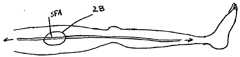
Translated fromKorean본 발명은 혈관 보철, 특히, 표면 대퇴 동맥(SFA)에서 발생할 가능성이 있는 주기성 축방향 또는 비틀림 하중을 받는 혈관에 사용하기 위한 혈관 보철에 관한 것이다. 특히, 본 발명은 복수의 나선형으로 배열된 쌍안정 셀을 포함하는 혈관 보철에 관한 것이다.The present invention relates to vascular prostheses, in particular for use in vessels subjected to periodic axial or torsional loads that are likely to occur in the surface femoral artery (SFA). In particular, the present invention relates to vascular prostheses comprising a plurality of spirally arranged bistable cells.
통상적으로 "스텐트"라 지칭되는 혈관 보철은 이제 관상 대동맥 및 기타 혈관의 병변을 치료하기 위한 중재 시술에서 널리 사용되고 있다. 이런 장치는 일반적으로 관형 형상을 가지며, 혈관의 세그먼트의 개방성을 복원 및 유지하기 위해 혈관 내에서 전개된다. 보다 최근에, 이런 혈관 보철은 혈관의 재협착을 방지하기 위한 국지적 약물 전달 및/또는 방사선 요법과 조합하여 사용되었다.Vascular prostheses, commonly referred to as "stents", are now widely used in interventional procedures to treat lesions of coronary aorta and other blood vessels. Such devices generally have a tubular shape and are deployed within the vessel to restore and maintain the openness of the segment of the vessel. More recently, such vascular prostheses have been used in combination with local drug delivery and / or radiation therapy to prevent vascular restenosis.
이전에 알려진 혈관 보철은 일반적으로 자체 팽창 또는 소성 변형가능하며, 이런 스텐트는 심장 맥관구조 외부에 사용되어 성공과 실패를 겪어왔다. 스텐팅(stenting)은 심장 혈관의 협소화를 치료하기 위해 가장 일반적으로 수행되고 있지만, 보다 최근의 노력은 목동맥, 신장 동맥 및 표면 대퇴 동맥의 폐색성 질환을 치료하기 위해 이런 장치의 사용에 집중되고 있다. 이런 용례에 사용되는 스텐트는 심장 스텐팅에 통상적으로 사용되는 것들과는 다른 구조적 특성의 집합을 필요로 하는 경우가 많다.Previously known vascular prostheses are generally self-expansible or plastically deformable, and these stents have been used outside the cardiac vasculature to experience success and failure. Stenting is most commonly performed to treat cardiovascular narrowing, but more recent efforts have focused on the use of such devices to treat obstructive diseases of the carotid, renal and superficial femoral arteries. have. Stents used in these applications often require a different set of structural characteristics than those commonly used for cardiac stents.
팔마즈(Palmaz)에게 허여된 미국 특허 제4,733, 665호는 벌룬 카테터를 거쳐 경혈관으로 전달되는 소성 변형가능한 스텐트의 전형이다. 이 특허에 개시된 스텐트는 와이어 메시 튜브 또는 슬롯형 금속 튜브로 구성된다. 이 스텐트는 전달 카테터의 벌룬 둘레에 크림핑되며, 스텐트의 스트러트(strut)를 소성 변형 및 팽창시키도록 고압으로 벌룬을 팽창시킴으로써 전개된다. 비록, 이런 스텐트가 심장 혈관의 폐색성 질환을 치료하기 위해 적합한 것으로 검증되었지만, 이들은 심장 맥관구조의 외부에 사용될 때 다수의 잘 알려진 단점을 갖는다.U. S. Patent No. 4,733, 665 to Palmaz is typical of plastically deformable stents delivered via a balloon catheter to the menstrual vessels. The stent disclosed in this patent consists of wire mesh tubes or slotted metal tubes. This stent is crimped around the balloon of the delivery catheter and developed by inflating the balloon at high pressure to plastically deform and expand the strut of the stent. Although these stents have proven to be suitable for treating cardiovascular obstructive diseases, they have a number of well-known disadvantages when used outside of the cardiac vasculature.
예로서, 이전에 알려진 소성 변형가능한 스텐트는 일반적으로 목동맥 또는 팔다리 내의 동맥 같은 압축성 또는 다른 형태의 동적 부하를 받는 혈관을 위해서는 부적합하다. 이들은 일반적으로 적절한 반경방향 강도를 제공하지만, 이들은 통상적으로 높은 정도의 축방향 강도도 갖는다. 따라서, 소성 변형가능한 스텐트는 규칙적으로 종방향 형상의 변화를 받는 혈관 내에 사용되어서는 안 되며, 그 이유는 스텐트가 혈관에 부합되기 위한 유연성이 결여되어 있고, 혈관의 파괴, 변형 또는 절개를 유발할 수 있기 때문이다.For example, previously known plastically deformable stents are generally unsuitable for vessels subject to compressive or other forms of dynamic loading, such as arteries in the carotid or limbs. They generally provide adequate radial strength, but they typically also have a high degree of axial strength. Therefore, plastically deformable stents should not be used in blood vessels that regularly undergo longitudinally varying shape, because the stent lacks the flexibility to fit the blood vessels and may cause breakage, deformation or incision of the blood vessels. Because there is.
예로서, 샤쯔(Schatz)에게 허여된 미국 특허 제5,195,984호에 설명된 바와 같이, 소성 변형가능한 스텐트의 인접 원주방향 링이 굴곡될 수 있게 하고, 혈관 약물 전달의 형상에 부합되는 유연한 축방향 링크를 설계하는데 최근 10년간 많은 노력이 이루어져 왔다. 그러나, 이런 링크는 또한 소성 변형가능한 재료를 포함한다. 비록, 링크가 최초 전개 동안 제한된 양의 굴곡 변형을 받을 수 있지만, 이들은 예로서, 굴곡을 받는 주변 혈관 내의 다수의 굴곡 사이클을 받을 때 신속히 가공-경화되며 파괴된다.For example, as described in US Pat. No. 5,195,984 to Schatz, the adjacent circumferential ring of plastically deformable stents can be bent and a flexible axial link that conforms to the shape of vascular drug delivery. Much effort has been made in the last decade of design. However, such links also include plastically deformable materials. Although the links may be subject to a limited amount of flexion deformation during initial deployment, they are rapidly processed-hardened and destroyed, for example, when undergoing multiple flexing cycles in the periphery of the vessel being flexed.
부가적으로, 소성 변형가능한 스텐트는 매우 미소한 탄성을 갖기 때문에, 상술한 특허의 스텐트는 목동맥 같은 높은 반경방향 압축력을 받는 혈관에 사용하기에는 부적합하다. 목동맥은 목의 표면에 비교적 근접하게 배치되어 있기 때문에, 스텐트가 목에 대한 타격 또는 기타 압력에 의해 우발적으로 부서질 수 있는 현저한 위험이 있다. 이 때문에, 왈스텐(Wallsten)에게 허여된 미국 특허 제4,655,771호에 설명된 메시-튜브 구조체 같은 자체 팽창 스텐트 및 초탄성 형상 기억 재료로 형성된 튜브가 동적 부하를 받는 혈관에서는 주요 관심이었다.In addition, because the plastically deformable stent has a very small elasticity, the stent of the above-described patent is not suitable for use in high radial compressive vessels such as carotid arteries. Because the carotid artery is located relatively close to the surface of the neck, there is a significant risk that the stent may be accidentally broken by striking or other pressure on the neck. Because of this, tubes formed from self-expanding stents and superelastic shape memory materials, such as the mesh-tube structures described in US Pat. No. 4,655,771 to Wallsten, were of primary interest in vessels under dynamic loading.
자체 팽창 스텐트는 일반적으로 왈스텐의 상술한 특허에서 같이 와이어 메시 튜브로서 형성되며, 이 튜브는 지안투르코(Gianturco)에게 허여된 미국 특허 제4,580,568호에 개시된 바와 같은 단일 또는 다수의 원주방향 링, 크리머(Kreamer)에게 허여된 미국 특허 제4,740,207호에 개시된 바와 같은 코일형 시트 또는 가르자(Garza) 등에게 허여된 미국 특허 제4,665,918호에 개시된 바와 같은 자체 팽창 헬릭스(helix)를 포함한다.The self-expanding stent is generally formed as a wire mesh tube as in the aforementioned patent of Walsten, which tube is a single or multiple circumferential ring as disclosed in US Pat. No. 4,580,568 to Gianturco, Coiled sheets as disclosed in US Pat. No. 4,740,207 to Kreamer or self-expansion helix as disclosed in US Pat. No. 4,665,918 to Garza et al.
왈스텐의 상술한 특허에 개시된 유형의 자체 팽창 와이어 메시 튜브 및 크리머의 상술한 특허에 개시된 바와 같은 코일형 시트 튜브는 높은 수준의 내파괴성을 제공하지만, 종방향으로 굴곡되거나 축방향 압축성 부하를 지탱하는 제한된 기능만을 갖는다. 또한, 지안투르코의 상술한 특허에 개시된 바와 같은 자체 팽창 링 구 조체는 양호한 반경방향 내파괴성을 제공하지만, 높은 반경방향 강도를 제공하지 못하며, 주기성 압축을 받는 경우 이동되게 된다.Self-expanding wire mesh tubes of the type disclosed in the aforementioned patents of Walsten and coiled sheet tubes as disclosed in the aforementioned patents of creamers provide a high level of fracture resistance, but withstand longitudinally curved or axial compressive loads. Has only limited functionality. In addition, self-expanding ring structures as disclosed in Gianturco's aforementioned patents provide good radial fracture resistance, but do not provide high radial strength and are moved when subjected to periodic compression.
이런 용례를 위해 가장 유망할 수 있는 가르자의 상술한 특허에 개시된 유형의 나선형 스텐트는 종방향 굴곡 및 반경방향 압축성 부하를 견딜 수 있는 것으로 나타난다. 그러나, 자체 팽창 나선형 스텐트도 표면 대퇴 동맥("SFA")에서 겪게되는 바와 같은 주기성 축방향 압축 및/또는 비틀림 하중을 받을 때 적절하게 기능할 수 없을 것으로 예상된다.The most promising for this application is the spiral stent of the type disclosed in the aforementioned patent of Garza, which appears to be able to withstand longitudinal bending and radial compressive loads. However, it is anticipated that even self-expanding helical stents may not function properly when subjected to periodic axial compression and / or torsional loading as experienced in surface femoral arteries (“SFAs”).
대퇴 동맥은 사타구니 영역의 장골 동맥으로부터 다리를 향해 연장하며, SFA는 무릎과 발에 혈액을 공급한다. 동맥경화 및 당뇨병의 혈관 합병증 같은 이들 혈관을 폐색하는 질환을 갖는 환자는 종종 감소된 이동성을 겪으며, 극단적 경우에는 절단이 필요할 수 있다.The femoral artery extends from the iliac artery in the groin area towards the leg, and SFA supplies blood to the knees and feet. Patients with diseases that obstruct these vessels, such as atherosclerosis and vascular complications of diabetes, often suffer from reduced mobility and, in extreme cases, amputation may be necessary.
대퇴의 굴곡 동안, 대퇴 동맥은 축방향 압축 및/또는 비틀림을 받으며, 이는 자체 팽창 나선형 스텐트에 반경방향 압축을 유발하는 것으로 예상된다. 이런 압축에 혈관의 단축(shortening)이 동반될 때, 스텐트는 압축성 부하가 제거되고 혈관이 반경방향으로 재팽창되고 나면 그 전달 부위로부터 멀어져 이동하기 쉽다. 비록, 스텐트의 탄성 거동이 바람직하고, 스텐트가 반경방향 압축성 부하를 극복하는 것을 가능하게 하지만, 이 동일한 특징은 반경방향 압축이 혈관 길이의 변화를 동반할 때 스텐트 이동 가능성을 심화시킨다. 결과적으로, 이전에 알려진 자체 팽창 나선형 스텐트는 주기성 축방향 및/또는 비틀림 하중을 받는 SFA 및 다른 혈관 내에서 전개될 때 만족스럽게 동작하지 못하는 것으로 예상된다.During flexion of the femur, the femoral artery is subjected to axial compression and / or torsion, which is expected to cause radial compression in the self-expanding spiral stent. When this compression is accompanied by vessel shortening, the stent is likely to move away from its delivery site after the compressive load has been removed and the vessel re-expanded radially. Although the elastic behavior of the stent is desirable and allows the stent to overcome radial compressive loads, this same feature increases the possibility of stent movement when the radial compression is accompanied by a change in vessel length. As a result, previously known self-expanding spiral stents are expected to fail satisfactorily when deployed in SFAs and other vessels subjected to periodic axial and / or torsional loads.
소성 변형 및 자체 팽창 구조체에 부가하여, "쌍안정 셀"의 개념에 기초한 새로운 유형의 팽창가능한 관형 구조체가 동시 계류 중인 함께 양도된 베셀링크(Besselink)의 미국 특허 출원 공개 제US2004/0193247호에 개시되어 있으며, 이 출원의 전문은 본 명세서에 참조로 통합되어 있다. 이 공개된 출원에 개시된 바와 같이, 쌍안정 셀은 반경방향 외향 지향력을 받을 때, 얇은 스트러트가 안정 절첩 위치와 안정 팽창 위치 사이에서 스냅되지만 임의의 중간 위치에서는 불안정하도록 단부에서 얇은 스트러트에 결합된 두꺼운 스트러트를 포함한다.In addition to plastic deformation and self-expansion structures, a new type of expandable tubular structure based on the concept of "bistable cells" is disclosed in US Patent Application Publication No. US2004 / 0193247 to Bessellink, co-pending. And the entirety of this application is incorporated herein by reference. As disclosed in this published application, a bistable cell is coupled to a thin strut at the end such that when subjected to radial outward orientation, the thin strut snaps between the stable folded position and the stable expanded position but is unstable at any intermediate position. Contains thick struts.
상술한 베셀링크 출원의 도 10이 샤쯔의 상술한 특허에서와 같이 스텐트의 축방향 유연성을 향상시키기 위한 가요성 링크의 사용을 개시하지만, 이 쌍안정 관형 구조체는 동적 축방향 굴곡 또는 압축성 부하를 받을 때 소성 변형가능한 스텐트와 유사한 단점을 갖는 것으로 예상된다.Although FIG. 10 of the aforementioned Bessellink application discloses the use of a flexible link to improve the axial flexibility of the stent as in the aforementioned patent of Shatz, this bistable tubular structure is subject to dynamic axial bending or compressive loading. It is expected to have similar drawbacks when plastically deformable stents.
이전에 알려진 혈관 보철의 상술한 단점의 견지에서, 축방향 및 비틀림 하중을 받는 혈관 내에 사용될 수 있지만, 잘 이동하지 않는 혈관 보철을 제공하는 것이 바람직하다.In view of the above-mentioned disadvantages of previously known vascular prostheses, it is desirable to provide vascular prostheses that can be used in vessels subjected to axial and torsional loads, but which do not move well.
또한, 현저한 반경방향 변형을 겪지 않고 높은 압축성 부하를 견딜 수 있어서 압축성 부하가 혈관 길이 변화를 동반할 때의 축방향 이동 가능성을 피할 수 있는 혈관 보철을 제공하는 것이 바람직하다.It would also be desirable to provide vascular prostheses that can withstand high compressive loads without experiencing significant radial deformation, thereby avoiding the possibility of axial movement when the compressive loads are accompanied by changes in vessel length.
또한, 높은 반경방향 강도를 갖지만, 또한, 신체 혈관 내에서 전개되고 나면, 높은 수준의 굴곡 피로에 대한 내성을 갖고 그 길이를 따라 굴곡될 수 있는 높은 반경방향 강도를 갖는 혈관 보철을 제공하는 것이 바람직하다.It is also desirable to provide vascular prostheses that have high radial strength, but also have high radial strength that, once deployed in body blood vessels, is resistant to high levels of flex fatigue and can be flexed along its length. Do.
또한, 압축성 부하의 존재시 혈관 벽과 접촉을 유지하지만, 또한, 주기적으로 인가되는 축방향 압축 및 인장 부하로 인한 파괴에 대해 내성을 갖도록 높은 반경방향 강도를 갖는 혈관 보철을 제공하는 것이 바람직하다.It would also be desirable to provide vascular prostheses with high radial strength to maintain contact with the vascular wall in the presence of compressive loads, but also to be resistant to breakage due to axial compression and tensile loads applied periodically.
SFA 및 유사 혈관을 스텐팅하기 위한 적절한 보철 디자인의 결여에 부가하여, 이런 동맥에 관련된 중재 시술은 특히, 이들 혈관 내의 스텐트의 크기설정 및 배치에 관한 다른 어려움을 겪는다. 일반적으로, 특정 환자 내에 사용되는 스텐트의 적절한 선택을 보장하도록 스텐트 배치 이전에 치료 부위의 크기 형상 및 위치를 확인할 필요가 있다. 이런 정보를 얻기 위해 조영제를 사용하는 형광투시 검사, 자기 공명 영상 및 컴퓨터 단층촬영을 포함하는 다수의 기술이 개발되어 왔다. 후자의 두 가지 방법이 혈관 지형(topography)의 양호한 모습을 제공하지만, 이 정보는 통상적으로 정적이고 실시간이 아닌 시술 이전의 정보이다.In addition to the lack of proper prosthetic design for stenting SFA and similar vessels, interventional procedures involving these arteries suffer from other difficulties, particularly with regard to the sizing and placement of the stents in these vessels. In general, it is necessary to confirm the size shape and location of the treatment site prior to stent placement to ensure proper selection of the stent for use within a particular patient. Many techniques have been developed to obtain this information, including fluoroscopy using contrast agents, magnetic resonance imaging, and computed tomography. While the latter two methods provide a good view of vascular topography, this information is typically information before the procedure, not static and real time.
목표 부위의 실시간 관찰을 위해 이전에 알려진 방법에서, 치료 부위에 대한 정보를 얻기 위해 스텐트 배치 이전에 혈관 내에 조영제(contrast agent)가 주입된다. 종종, 조영제의 사용은 예로서, 조영제가 혈류 내로 주입되고 나면 분산되는 경향이 있기 때문에 덜 이상적인 정확도를 제공한다. 이는 순차적으로 더 큰 양의 조영제의 사용을 필요로 할 수 있다. 부가적으로, 혈관이 크게 폐색된 경우, 매우 미소한 흐름이 존재할 수 있으며, 따라서, 폐색의 크기 및 심각성을 평가하기가 곤란할 수 있다.In a previously known method for real-time observation of a target site, a contrast agent is injected into the vessel prior to stent placement to obtain information about the treatment site. Often, the use of contrast medium provides less ideal accuracy, for example, because the contrast agent tends to disperse once injected into the bloodstream. This may in turn require the use of larger amounts of contrast agent. In addition, if the blood vessels are largely occluded, very small flows may be present, thus making it difficult to assess the size and severity of the obstruction.
결과적으로, 치료 부위에 대한 정보를 얻기 위해 필요한 조영제의 양을 감소시키는 혈관 내에 혈관 보철을 배치하기 위한 방법 및 장치를 제공하는 것이 바람직하다.As a result, it would be desirable to provide a method and apparatus for placing vascular prostheses in blood vessels that reduces the amount of contrast agent needed to obtain information about the treatment site.
이전에 알려진 혈관 보철의 상술한 단점의 견지에서, 본 발명의 목적은 축방향 및 비틀림 하중을 받는 혈관 내에 사용될 수 있으면서 이동 경향이 적은 혈관 보철을 제공하는 것이다.In view of the above-mentioned disadvantages of previously known vascular prostheses, it is an object of the present invention to provide vascular prostheses which are less prone to movement while being able to be used in vessels subjected to axial and torsional loads.
또한, 본 발명의 목적은 현저한 반경방향 변형을 받지 않고 높은 압축성 부하를 견뎌서 압축성 부하가 혈관 길이의 변화를 동반할 때 축방향 이주 가능성을 피할 수 있는 혈관 보철을 제공하는 것이다.It is also an object of the present invention to provide a vascular prosthesis that can withstand high compressive loads without undergoing significant radial deformation, thereby avoiding the possibility of axial migration when the compressive load is accompanied by a change in vessel length.
또한, 본 발명의 목적은 높은 반경방향 강도를 가지며, 신체 혈관 내에서 전개되고 나면, 굴곡 피로에 대한 높은 수준의 내성을 가지며 그 길이를 따라 굴곡될 수 있는 혈관 보철을 제공하는 것이다.It is also an object of the present invention to provide a vascular prosthesis that has high radial strength and, once deployed in body blood vessels, has a high level of resistance to flex fatigue and can be curved along its length.
본 발명의 다른 목적은 압축성 부하의 존재시 혈관 벽과 접촉을 유지하고, 주기적으로 인가되는 축방향 압축 및 인장 부하로 인한 파괴에 대해 높은 내성을 가지도록 높은 반경방향 강도를 가지는 혈관 보철을 제공하는 것이다.Another object of the present invention is to provide a vascular prosthesis with high radial strength to maintain contact with the vessel wall in the presence of compressive loads and to have high resistance to fracture due to cyclic compression and tensile loads applied periodically. will be.
본 발명의 또 다른 목적은 치료 부위에 대한 정보를 얻기 위해 요구되는 조영제의 용적을 감소시키는, 혈관 내에 혈관 보철을 위치시키기 위한 방법과 장치를 제공하는 것이다.It is yet another object of the present invention to provide a method and apparatus for positioning vascular prostheses in blood vessels, which reduces the volume of contrast agent required to obtain information about the site of treatment.
이들 및 다른 장점은 복수의 상호연결된 쌍안정 셀을 포함하는 나선형 본체를 구비한 혈관 보철을 제공함으로써 달성된다. 각 쌍안정 셀은 반경방향 외향 지향력을 받을 때 안정 절첩 위치와 안정 팽창 위치 사이에서 얇은 스트러트가 스냅하지만 임의의 중간 위치에서는 불안정하도록 단부에서 얇은 스트러트에 결합된 두꺼운 스트러트를 포함한다. 인접한 셀들은 나선형 구조를 형성하도록 서로 결합되고, 셀들의 얇은 스트러트 및 두꺼운 스트러트는 실질적으로 헬릭스의 종축에 대하여 정렬된다. 바람직하게는 보철은 니켈-티타늄 같은 형상 기억 합금을 포함하고, 부가적으로 약물이나 다른 생물작용 보조제를 전달하기 위한 생분해성의(biodegradable 중합성 코팅을 포함할 수 있다.These and other advantages are achieved by providing a vascular prosthesis with a helical body comprising a plurality of interconnected bistable cells. Each bistable cell includes a thick strut coupled to the thin strut at the end such that the thin strut snaps between the stable folded position and the stable inflation position when subjected to radial outward orientation but is unstable at any intermediate position. Adjacent cells are joined to each other to form a helical structure, wherein the thin struts and thick struts of the cells are substantially aligned with respect to the longitudinal axis of the helix. Preferably the prosthesis comprises a shape memory alloy, such as nickel-titanium, and may additionally comprise a biodegradable polymerizable coating for delivering drugs or other bioactive aids.
본 발명의 혈관 보철은 이전에 알려진 스텐트 디자인의 것보다 우월한 성능을 제공하는 것으로 예상된다. 나선형 스텐트에 공통적인 것으로서, 본 발명의 나선형 구조체는 높은 굴곡 응력을 받지 않고 헬릭스의 종축에 대하여 스텐트가 쉽게 굴곡될 수 있게 한다. 부가적으로, 헬릭스의 인접한 권회부들 사이에 간극을 제공함으로써, 스텐트는 주기성 축방향 및/또는 비틀림 하중을 견딜 수 있다.The vascular prosthesis of the present invention is expected to provide superior performance over that of previously known stent designs. As common to helical stents, the helical structure of the present invention allows the stent to bend easily with respect to the longitudinal axis of the helix without being subjected to high bending stresses. Additionally, by providing a gap between adjacent windings of the helix, the stent can withstand periodic axial and / or torsional loads.
또한, 본 발명의 원리에 따라서, 쌍안정 셀의 헬릭스를 포함하는 혈관 보철은 이전에 알려진 나선형 스텐트 디자인에 비해 우수한 내파괴성을 제공하는 것으로 예상된다. 특히, 본 발명의 혈관 보철은 혈관의 축방향 길이가 변하는 경우에도 혈관 벽과 견고히 결합된 상태를 유지하며, 축방향 이동에 저항한다.In addition, according to the principles of the present invention, vascular prostheses comprising the helix of bistable cells are expected to provide superior fracture resistance compared to previously known spiral stent designs. In particular, the vascular prosthesis of the present invention remains firmly coupled to the vessel wall even when the axial length of the vessel changes, and resists axial movement.
압축 부하를 받을 때 쌍안정 셀이 큰 탄성 변형을 받지 않기 때문에, 헬릭스의 개별 권회부는 혈관 벽에 관해 종방향으로 잘 이동하지 않으며, 그에 의해, 주기성 축방향 및/또는 비틀림 하중을 받는 혈관 내에서 스텐트가 전개될 때 이동을 피한다.Since the bistable cells do not undergo large elastic deformation when subjected to compressive loads, the individual windings of the helix do not move well longitudinally with respect to the vessel wall, thereby allowing intravascular vessels under periodic axial and / or torsional loads. Avoid movement when the stent is deployed in the
본 발명의 다른 양태에 따라서, 본 발명의 스텐트가 이식될 수 있는 혈관을 관찰하기 위해 사용될 수 있는 관찰 카테터가 제공된다. 관찰 카테터의 사용 방법 및 스텐트의 이식 방법도 제공된다.According to another aspect of the present invention, an observation catheter is provided that can be used to observe blood vessels into which the stent of the present invention can be implanted. Methods of using a catheter and implantation of a stent are also provided.
본 발명의 상술한 바 및 다른 목적들과 장점은 전반에 걸쳐 동일 참조 번호가 동일 부분을 지시하고 있는 첨부 도면과 관련하여 이루어지는 하기의 상세한 설명의 고려시 명백해질 것이다.The foregoing and other objects and advantages of the present invention will become apparent upon consideration of the following detailed description taken in conjunction with the accompanying drawings, wherein like reference numerals designate like parts throughout.
도 1은 표면 대퇴 동맥("SFA")을 포함하는 인간의 다리의 대동맥 맥관구조의 개략도.1 is a schematic representation of the aortic vasculature of a human leg including the surface femoral artery (“SFA”).
도 2A 및 도 2B는 각각 무릎이 펴진 위치인 건강한 사람의 다리의 개략도 및 이 위치에서의 SFA의 개략도.2A and 2B are schematic diagrams of the legs of a healthy person in the extended knee position, respectively, and schematic diagrams of the SFA in this position.
도 3A 및 도 3B는 각각 무릎이 굴곡된 위치인 건강한 사람의 다리의 개략도 및 이 위치에서의 SFA의 개략도.3A and 3B are schematic diagrams of the legs of a healthy person with knees flexed, respectively, and schematic diagrams of SFA in this position;
도 4A, 도 4B 및 도 4C는 각각 동맥경화를 앓는 환자를 위한 도 3의 것과 유사한 환자의 다리의 개략도, 이 위치에서의 SFA의 개략도 및 이전에 알려진 스텐트가 스텐팅되었을 때의 SFA의 개략도.4A, 4B and 4C show schematic diagrams of a patient's leg similar to that of FIG. 3 for patients suffering from atherosclerosis, schematic diagrams of SFA at this location, and schematic diagrams of SFA when the previously known stent was stent.
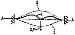
도 5A 내지 도 5C는 쌍안정 메커니즘의 원리를 예시하는 도면.5A-5C illustrate the principle of a bistable mechanism.
도 6은 도 1의 메커니즘의 힘-변위 특성을 도시하는 개략도.6 is a schematic diagram illustrating the force-displacement characteristics of the mechanism of FIG. 1.
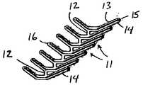
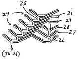
도 7A 및 도 7B는 각각 코일화되지 않고 펼쳐져 있는, 전개 구조와 전달 구조에서의 본 발명의 혈관 보철의 일부의 사시도.7A and 7B are perspective views, respectively, of a vascular prosthesis of the present invention in an unfolded and delivery structure, uncoiled and unfolded.
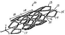
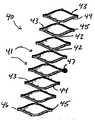
도 8A 및 도 8B는 각각 전개 구조와 전달 구조에서의 본 발명의 혈관 보철의 일부의 사시도.8A and 8B are perspective views of a portion of the vascular prosthesis of the present invention in deployment and delivery structures, respectively.
도 9A 및 도 9B는 코일화되지 않고 펼쳐져 있는, 전개 구조 및 전달 구조에서의 본 발명의 대안적 혈관 보철의 사시도.9A and 9B are perspective views of an alternative vascular prosthesis of the present invention in an unfolded and delivery structure, uncoiled.
도 10A 및 도 10B는 코일화되지 않고 펼쳐져 있는, 전개 구조 및 전달 구조에서의 본 발명의 다른 대안적 보철의 사시도.10A and 10B are perspective views of another alternative prosthesis of the present invention in an unfolded and delivery structure, uncoiled and unfolded.
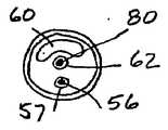
도 11A 및 도 11B는 각각 본 발명의 혈관 보철과 함께 사용하기에 적합한 관찰 카테터의 사시도 및 단면도.11A and 11B are perspective and cross-sectional views, respectively, of a viewing catheter suitable for use with the vascular prosthesis of the present invention.
도 12A 내지 도 12F는 본 발명의 원리에 따라 구성된 혈관 보철을 이식하는 방법을 예시하는 도면.12A-12F illustrate a method of implanting vascular prostheses constructed in accordance with the principles of the present invention.
본 발명은 복수의 쌍안정 셀로 형성된, 나선형 구조를 갖는 혈관 보철에 관한 것이다. 본 발명의 혈관 보철(이하, "스텐트"라고도 지칭됨)의 쌍안정 동작 모드는 이전에 공지된 소성 변형가능 스텐트의 능동적 고정 특성과 반경방향 압축력에 대한 우수한 내성을 갖는 이전에 공지된 자체 팽창 나선형 스텐트의 우수한 피로 내성을 조합한다. 결과는 낮은 이동가능성과 개선된 피로 내성 및 높은 반경방향 강도를 갖는 혈관 보철이다.The present invention relates to a vascular prosthesis having a spiral structure formed of a plurality of bistable cells. The bistable mode of operation of the vascular prosthesis of the present invention (hereinafter also referred to as “stent”) is a previously known self-expanding spiral that has the active fixation properties of previously known plastically deformable stents and excellent resistance to radial compression forces. Combine the excellent fatigue resistance of the stent. The result is vascular prostheses with low mobility, improved fatigue resistance and high radial strength.
본 발명의 혈관 보철은 표면 대퇴 동맥 같은 동적 부하를 받는 혈관 내에 전개될 때 특히 유리한 것으로 예상된다. 이런 혈관 내에 자체 팽창 스텐트 및 소성 변형가능 스텐트를 사용하려는 시도는 종종 주기성 축방향 부하로 인한 피로 파괴, 이동 또는 양자 모두로 인한 스텐트의 파괴를 초래한다.Vascular prostheses of the present invention are expected to be particularly advantageous when deployed in blood vessels under dynamic loading such as superficial femoral arteries. Attempts to use self-expanding stents and plastically deformable stents in such vessels often result in the failure of the stent due to fatigue failure, movement, or both due to periodic axial loading.
도 1을 참조하면, 본 발명의 표면 대퇴 동맥(SFA)의 폐색 질환을 치료하기 위한, 스텐트를 위한 예시적 용례가 설명된다. 다리에서의 SFA의 위치는 대퇴(F), 무릎뼈(P), 경골(T), 및 비골(FB)에 관하여 도시되어 있다. 특히, SFA는 무릎의 뼈에 대해 후방으로 통과한다. 따라서, 다리가 주기적으로 굽혀졌다 펴졌다 할 때, SFA는 가변적인 인장 및 압축 정도를 받게 된다. 이는 이전에 알려진 SFA 내의 스텐팅 시도의 손상 원인이 되는 것으로 믿어지는 주기성 축방향 부하이다.Referring to FIG. 1, an exemplary application for a stent for treating occlusion disease of the surface femoral artery (SFA) of the present invention is described. The location of the SFA in the leg is shown with respect to the femur (F), knee bone (P), tibia (T), and fibula (FB). In particular, the SFA passes rearward against the bone of the knee. Thus, when the legs are bent and stretched periodically, the SFA is subjected to varying degrees of tension and compression. This is a periodic axial load believed to cause damage to stent attempts in previously known SFAs.
도 2A 내지 도 3B에 관하여, 건강한 사람 내의 SFA의 부하가 이제 설명된다. 도 2A에서, 사람이 서 있을 때 같이 완전히 펼쳐진 무릎을 갖는 건강한 사람의 다리가 도시되어 있다. 이 위치에서, SFA는 도 2B에 화살표로 도시된 바와 같이 인장력을 받으며, 직선화된 긴 형상으로 당겨진다. 축방향 부하에 부가하여, 이런 인장 부하도 혈관의 직경을 미소하게 감소시키는 경향이 있다.With reference to FIGS. 2A-3B, the loading of SFA in a healthy person is now described. In FIG. 2A, the leg of a healthy person is shown with the knees fully extended as the person is standing. In this position, the SFA is tensioned as shown by the arrow in FIG. 2B and pulled into a straight, elongated shape. In addition to the axial load, this tensile load also tends to reduce the diameter of the blood vessels slightly.
대조적으로, 도 3A에 도시된 바와 같이, 환자가 앉거나 걸을 때 같이 환자의 무릎이 굽혀질 때, SFA상의 인장력은 혈관의 길이를 단축시키는 압축 부하로 대체된다. 이들 압축 부하는 도 3B에 화살표로 예시되어 있다. 부가적으로, 압축성 축방향 부하는 혈관의 직경을 미소하게 팽창시키는 경향이 있다. 건강한 사람의 경우에, SFA는 탄성적으로 남아 있으며, 그 길이 및 직경 양자 모두를 변경함으로써 주기적 인장 및 압축 부하에 응답한다.In contrast, as shown in FIG. 3A, when the patient's knee is bent, such as when the patient is sitting or walking, the tension on the SFA is replaced by a compressive load that shortens the length of the vessel. These compression loads are illustrated by arrows in FIG. 3B. In addition, the compressive axial load tends to slightly expand the diameter of the blood vessel. In healthy people, the SFA remains elastic and responds to cyclic tensile and compressive loads by changing both its length and diameter.
동맥경화 환자에서, 비교적 강성적인 플라크가 혈관의 내부상에 누적된다. 이 동맥의 강성화는 반경방향 및 종방향 양자 모두로의 혈관의 탄성의 감소를 초래하며, 그에 의해, 주기성 부하에 대응하는 혈관의 기능을 현저히 감소시킨다. 또 한, 혈관 내에 누적된 플라크는 혈관의 길이 및 원주를 따라 두께를 변화시키기 때문에, 혈관은 인장 및 압축성 부하에 비균일하게 반응하는 경향이 있다.In atherosclerotic patients, relatively rigid plaques accumulate on the inside of blood vessels. This stiffening of the artery results in a decrease in the elasticity of the blood vessels in both radial and longitudinal directions, thereby significantly reducing the function of the blood vessels in response to periodic loads. In addition, because plaque accumulated in the blood vessels varies in thickness along the length and circumference of the blood vessels, the blood vessels tend to react non-uniformly to tensile and compressive loads.
상술한 현상은 무릎의 굴곡에 의해 인가되는 압축성 부하에 석회화된 SFA가 반응하는 방식을 개략적으로 도시하는 도 4A 및 도 4B에 예시되어 있다. 무릎이 굴곡될 때, 혈관에 인가된 힘은 인장으로부터 압축으로 전이한다. 플라크 침전물이 압축성 부하하에서의 혈관의 반경방향 팽창 및 균일한 단축을 방지하기 때문에, 혈관은 그 종축을 따라 변형하고 왜곡되는 경향이 있다. 결과적으로, 혈관의 국지적 영역은 집중된 굴곡 및/또는 압축 부하를 받는다.The above-mentioned phenomenon is illustrated in Figures 4A and 4B, which schematically illustrate how the calcified SFA reacts to compressive loads applied by flexion of the knee. When the knee is flexed, the force applied to the blood vessels transitions from tension to compression. Because plaque deposits prevent radial expansion and uniform shortening of the vessel under compressive loading, the vessel tends to deform and distort along its longitudinal axis. As a result, the local region of the blood vessel is subjected to concentrated bending and / or compression loads.
도 4C는 예로서, 하지의 허혈을 경감시키기 위해 도 4A 및 도 4B의 혈관 내에 이전에 알려진 소성 변형가능한 스텐트를 이식하는 효과를 예시한다. 도 4C에 도시된 바와 같이, 스텐트가 이식된 영역은 축방향 및 반경방향 양자 모두로 실질적으로 강체가 된다. 결과적으로, 다리의 굴곡 동안 혈관이 단축될 때, SFA의 다른 부분은 더 큰 왜곡 및 변형을 유발함으로써 스텐팅된 영역의 강도를 보상한다. 또한, 스텐팅된 영역의 증가된 강도는 스텐트의 단부 부근에 혈관 굴곡 및 왜곡을 집중시키는 경향이 있으며, 그에 의해, 혈관상의 요구치를 증가시키고, 혈관에 인가된 국지적 힘을 심화시킨다. 이는 혈관 내의 흐름 제한 결함(flow-limiting kink)의 형성을 초래할 수 있다.4C illustrates, for example, the effect of implanting a previously known plastically deformable stent into the blood vessels of FIGS. 4A and 4B to relieve ischemia of the lower extremity. As shown in FIG. 4C, the area in which the stent is implanted is substantially rigid in both axial and radial directions. As a result, when blood vessels shorten during flexion of the legs, other parts of the SFA compensate for the strength of the stent area by causing greater distortion and deformation. In addition, the increased strength of the stent area tends to concentrate blood vessel flexion and distortion near the end of the stent, thereby increasing the blood vessel demand and deepening the local force applied to the vessel. This can lead to the formation of flow-limiting kinks in the blood vessels.
SFA의 개방성을 복원하기 위해 이전에 알려진 자체 팽창 나선형 스텐트를 사용하는 것은 더 큰 축방향 유연성을 제공하지만, 이런 스텐트는 스텐트 이동을 피하기 위한 충분한 반경방향 강도를 제공하지 않는다. 예로서, 자체 팽창 나선형 스텐트가 반복적 축방향 부하를 받을 때, 혈관의 직경의 국지적 변화는 나선형 스텐트의 직경이 변동되게 할 수 있다. 이는 순차적으로 스텐트 헬릭스의 인접한 권회부들이 변위되게 하고, 결과적으로, 다수의 부하 사이클 이후, 스텐트가 그 원래의 전개 부위로부터 이동할 수 있다. 밀집적으로 석회화된 영역에서, 인접 셀은 경사질 수 있고, 스텐트상의 동심 포컬 응력(cocentric focal stress)으로 인해 혈관 내의 흐름을 제한할 수 있다.Using previously known self-expanding spiral stents to restore the openness of the SFA provides greater axial flexibility, but these stents do not provide sufficient radial strength to avoid stent movement. For example, when the self-expanding helical stent is subjected to repeated axial loading, a local change in the diameter of the vessel can cause the diameter of the helical stent to vary. This in turn causes adjacent windings of the stent helix to be displaced, and consequently, after multiple load cycles, the stent can move from its original deployment site. In the densely calcified area, adjacent cells may be inclined and may restrict flow in the vessel due to cocentric focal stress on the stent.
본 발명의 혈관 보철은 높은 종방향 유연성을 갖지만, 높은 반경방향 강도를 제공하는 혈관 보철을 제공함으로써, 이전에 알려진 스텐트 디자인의 이들 문제점을 해결한다. 특히, 본 발명의 혈관 보철의 쌍안정 셀은 반경방향 부하에 대응하기 위한 높은 반경방향 강도를 제공하고, 축방향 압축성 및 높은 내파괴성을 제공하는 나선형 배열로 구성된다.The vascular prostheses of the present invention solve these problems of previously known stent designs by providing vascular prostheses with high longitudinal flexibility, but providing high radial strength. In particular, the bistable cells of the vascular prosthetics of the present invention are constructed in a spiral arrangement that provides high radial strength to counter radial loads and provides axial compressibility and high fracture resistance.
이제, 도 5A 내지 도 6을 참조하면, 쌍안정 동작 모드의 원리가 설명된다. 도 5A는 길이(L)를 가지며, 각 단부에서 고정되어 있는 로드(1)를 도시한다. 로드(1)가 축방향으로 압축될 때, 이는 도 5B에 도시된 그 좌굴 응력에 도달하며, 이 때, 로드의 중앙 부분은 각각 상부 안정 위치(2) 또는 하부 안정 위치(3)(도 5B에 점선으로 도시됨)로 측방향으로 외향 굴곡한다. 로드(1)의 단부의 축방향 변위(ΔL)가 외부 클램프(4)에 의해 안정하게 위치될 때, 상부 안정 위치(2)와 하부 안정 위치(3) 사이에서 로드의 중앙 부분을 이동시킬 수 있다. 이러한 이동은 로드의 종축(A-A)에 수직인 방향(X)이다. 상부 안정 위치(2)와 하부 안정 위치(3) 사이의 모든 위치는 불안정하다. 도 5B에 도시된 바와 같이, 로드가 방향(X)으로 이동할 수 있기 이전에, 로드의 중앙부는 각도(β)를 통해 회전한다. 도 5C는 각도(β)에 걸친 회전이 로드(1)의 중앙부를 클램핑하고 이 부분을 축(A-A)에 평행하게 유지함으로써 맞서지게 될 때 발생하는 로드(1) 내의 제 2 차 곡율을 도시한다.Referring now to FIGS. 5A-6, the principle of the bistable mode of operation is described. 5A shows the rod 1 having a length L and fixed at each end. When the rod 1 is compressed in the axial direction, it reaches its buckling stress shown in Fig. 5B, in which the central part of the rod is the upper
도 6을 참조하면, 변위(X)를 통해 로드(1)의 중앙부를 이동시키기 위해 필요한 힘(F)이 변위(X)의 함수로서 도시되어 있으며, X는 수평 방향으로 표시되어 있다. 로드(1)가 도 1의 상부 안정 위치(2)로부터 하부 안정 위치(3)로 이동할 때, 힘(F)은 0으로부터 Fmax까지 증가한다. 이 순간에, 도 5B 또는 도 5C의 제 1 차 또는 제 2 차 곡율이 도달되고, 로드는 상부 안정 위치(2)로부터 하부 안정 위치(3)로 전이한다. 또한, 시스템이 음의 탄성율(spring rate)을 갖기 때문에, 방향(X)으로의 변위는 더 작은 힘을 필요로 한다.With reference to FIG. 6, the force F required to move the center part of the rod 1 via the displacement X is shown as a function of the displacement X and X is indicated in the horizontal direction. When the rod 1 moves from the upper
도 6의 힘 변위 곡선은 완전히 대칭적이며, 따라서, 로드를 하부 위치로부터 상부 위치로 복귀 이동시키기 위해 필요한 힘은 동일한 특성을 갖는다. 이 쌍안정 동작 모드는 두꺼운 스트러트가 도 5B 및 도 5C의 외부 클램프(4)의 기능을 수행하도록 얇은 스트러트가 그 단부에서 두꺼운 스트러트에 연결되어 있는 유닛 셀을 생성함으로써 달성될 수 있다. 따라서, 얇은 스트러트는 외력의 인가를 통해 제 1 안정 위치와 제 2 안정 위치 사이에서 이동할 수 있지만, 임의의 중간 위치에서는 불안정할 것이다. 결과적인 유닛 셀은 반경방향 외향력의 인가가 얇은 스트러트가 두꺼운 스트러트에 인접하게 위치되어 있는 수축 위치로부터 얇은 스트러트가 두꺼운 스트러트로부터 멀어지는 방향으로 굴곡되어 있는 팽창된 위치로 유닛 셀이 팽창되게 한다.The force displacement curve of FIG. 6 is completely symmetrical, so that the force required to move the rod back from the lower position to the upper position has the same characteristics. This bistable mode of operation can be achieved by creating a unit cell in which a thin strut is connected to the thick strut at its end such that the thick strut performs the function of the outer clamp 4 of FIGS. 5B and 5C. Thus, the thin strut can move between the first stable position and the second stable position through the application of an external force, but will be unstable at any intermediate position. The resulting unit cell causes the application of the radial outward force to expand the unit cell from the retracted position where the thin strut is located adjacent to the thick strut and the expanded position where the thin strut is bent away from the thick strut.
이제, 도 7A 내지 도 8B을 참조하면, 본 발명의 혈관 보철의 제 1 실시예가 설명된다. 혈관 보철(10)은 도 7A에 말려지지 않고 펼쳐진 상태, 예로서, 형상 기억 재료의 시트로부터의 절단체로서 도시되어 있으며, 도 8A 및 도 8B에서, 혈관 보철(10)은 유닛 셀이 나선형 구조를 취하도록 적절한 성형 및 열 처리 이후의 상태로 도시되어 있다. 혈관 보철(10)은 브리지(12)에 의해 상호연결된 복수의 유닛 셀(11)을 포함한다. 각 유닛 셀(11)은 그 단부에서 두꺼운 스트러트(14)에 결합된 얇은 스트러트(13)를 포함한다. 본 발명의 원리에 따라, 유닛 셀(11)은 쌍안정하다.Referring now to FIGS. 7A-8B, a first embodiment of the vascular prosthesis of the present invention is described. The
상술된 바와 같이, 유닛 셀(11)은 두 개의 안정한 구조, 즉, 팽창된, 완전히 전개된 구조(도 7A)와 절첩된 완전히 수축된 전달 구조(도 7B)를 갖는다. 유닛 셀(11)은 인가된 힘이 셀이 다른 안정 위치로 전이하는 Fmax에 도달할 때까지 셀을 중간 위치로 변형시키는 임의의 힘에 저항한다. 얇은 스트러트(13)를 전달 구조로부터 전개된 구조로 전이시키기 위해 필요한 힘은 셀의 형상과, 셀을 구성하는 재료와, 보철을 제조하기 위해 사용된 처리 방법의 함수이다. 이들 중, 유닛 셀의 쌍안정 기능은 얇은 스트러트(13) 대 두꺼운 스트러트(14)의 두께의 비율에 의해 크게 영향을 받으며, 1:2 내지 1:5의 두께 비율이 양호한 쌍안정 기능을 제공하는 것으로 예상된다.As described above, the unit cell 11 has two stable structures, an expanded, fully deployed structure (FIG. 7A) and a folded fully contracted delivery structure (FIG. 7B). The unit cell 11 resists any force that deforms the cell to an intermediate position until the applied force reaches Fmax at which the cell transitions to another stable position. The force required to transfer the
혈관 보철(10)은 니켈-티타늄 합금 또는 기타 형상 기억 합금의 튜브를 레이저 절단 또는 화학적으로 에칭함으로써 형성될 수 있거나, 대안적으로, 스테인레스 강이나 생체친화성 또는 생분해성의 폴리머 같은 다른 재료로 구성될 수 있다. 대안적으로, 혈관 보철(10)은 평탄한 재료의 시트로부터 절단 또는 에칭되고, 그 후, 멘드릴과 원래 알려져 있는 적절한 열처리를 사용하여 나선형 관형 부재로 성형될 수 있다.The
인접한 유닛 셀(11)들은 서로로부터 오프셋되는 브리지들(12)에 의해 상호 연결되며, 따라서 상기 유닛 셀들은 나선형 관상 부재를 구성한다. 적합하게도, 상기 유닛 셀들은 미리 결정된 수만큼의 셀들이 헬릭스의 단일 권회부에 배치되고 또한 타게트 용기에 채용될 때 대체로 평탄한 루멘을 형성하도록 치수 결정된다. 예시적으로, 도 8A 및 도 8B의 혈관 보철(10)의 헬릭스의 각 권회부는 6개의 유닛 셀을 포함하지만, 더 많거나 더 적은 수도 특정 용례나 혈관을 위해 적합한 바에 따라 사용될 수 있다.Adjacent unit cells 11 are interconnected by
도 7A 내지 도 8B를 계속 참조하면, 각 유닛 셀(11)은 원위 팁(15)과 근위 팁(16)을 포함하며, 이들 각각은 얇은 스트러트와 두꺼운 스트러트의 접합에 의해 형성되어 있다. 예시적으로, 원위 팁(15)에 결합하는 유닛 셀의 부분은 근위 팁(16)을 형성하기 위해 결합하는 부분보다 더 길고, 더 큰 예각을 형성한다. 그러나, 쌍안정 동작 모드는 원위 팁과 근위 팁이 대칭이거나, 심지어 반전된 경우의 유닛 셀로도 달성될 수 있다는 것을 이해하여야 한다. 본 발명의 일 양태에 따라서, 얇은 스트러트와 두꺼운 스트러트의 접합부는 소성 변형으로 또는 대안적으로 탄성적으로, 즉, 소성 변형이 미소하거나 없는 상태로, 전달 구조로부터 전개된 구조로의 얇은 스트러트의 전이를 가능하게 하도록 구성될 수 있다.With continued reference to FIGS. 7A-8B, each unit cell 11 includes a
전개된 위치로 전이되었을 때 각 유닛 셀(11)은 얇은 스트러트(13)와 두꺼운 스트러트(14)에 의해 한정된 개구(17)를 형성한다. 완전히 절첩된 전달 구조에서, 얇은 스트러트(13)는 두꺼운 스트러트(14)에 인접하게 배치되고, 그에 의해, 전달 구조에서 혈관 보철의 전체 직경을 감소시킨다. 도 7A 내지 도 8B에 도시된 바와 같이 배열되었을 때, 유닛 셀(11)을 전달 구조로부터 전개 구조로 전이시키는 것은 혈관 보철의 단축 없이 원주방향 팽창을 제공한다. 따라서, 유닛 셀(11)의 원위 팁 및 근위 팁은 헬릭스에 의해 형성된 루멘의 종방향 축과 양호하게 정렬된다.When transitioned to the deployed position, each unit cell 11 forms an
도 8A 및 도 8B를 참조하면, 본 발명의 혈관 보철(10)은 복수의 권회부를 갖는 헬릭스를 형성하도록 통합된 임의의 수의 유닛 셀을 포함할 수 있다. 일반적으로, 혈관 보철(10)의 길이는 특정 치료 부위 또는 용례를 위해 적합하게 선택될 수 있으며, 헬릭스 내에 원하는 수의 나선형 권회부(18)를 제공하도록 필요에 따라 다수의 유닛 셀을 포함할 수 있다. 바람직하게는 헬릭스의 하나의 나선형 권회부(18)의 원위 팁(15)은 인접한 나선형 권회부(18)의 유닛 셀(11)의 근위 팁(16)으로부터 사전결정된 거리로 이격 배치되며, 그래서, 인접한 나선형 권회부(18)들 사이의 간극은 인접 권회부의 근위 팁 및 원위 팁과 접촉하는 상태로 압축 부하를 견디는 기능 및 종방향 유연성을 제공한다. 이 간극은 원위 팁(15)과 근위 팁(16)이 서로 맞물리도록 유닛 셀을 배열함으로써 추가로 증가될 수 있다.8A and 8B, the
혈관 보철(10)은 종축(X)을 따라 삽입된 벌룬 카테터(미도시) 위에 배치되고, 그후, 유닛 셀이 도 8A에 도시된 전달 구조로 전이하도록 Fmax보다 큰 내향 지향 외력을 인가함으로써 크림핑될 수 있다. 혈관 보철(10)과 함께 사용하기 위한 적절한 전달 카테터는 본 기술 분야에 잘 알려진 바와 같이 외부 보호 외피를 갖거나 갖지 않는 비-유연성(non-compliant) 또는 반-유연성(semi-compliant) 벌룬을 구비한 임의의 상업적으로 입수할 수 있는 카테터를 포함할 수 있다.The
혈관 보철 및 카테터가 혈관 내의 원하는 위치로 피부를 통해 전진되고 나면, 벌룬이 팽창되어 유닛 셀이 내부면에 반경방향 외향 지향력을 인가한다. 도 8A의 헬릭스의 내부면에 인가된 힘이 Fmax를 초과할 때, 얇은 스트러트는 좌굴되어 도 8B의 완전히 팽창된 전개 구조로 전이된다. 유리하게는, 전이점을 초과하는 부가적인 힘이 미소하거나 없는 상태로 유닛 셀이 완전히 전개된 구조로 전이하기 때문에, 유닛 셀(11)은 이전에 알려진 소성 변형가능한 스텐트에서 겪는 과팽창 및 후속 되감김이 없이 목표 혈관의 내부면에 고착될 수 있다. 이는 순차적으로, 혈관 라이닝에 대한 상처를 감소시키고 네오인티멀 과다증식(neointimal hyperplasia)을 초래할 수 있는 부상-응답 메커니즘을 감소시키는 것으로 예상된다.Once the vascular prosthesis and catheter are advanced through the skin to the desired location in the vessel, the balloon is inflated to apply the radially outward directing force to the interior surface. When the force applied to the inner surface of the helix of FIG. 8A exceeds Fmax , the thin strut buckles and transitions to the fully expanded deployment structure of FIG. 8B. Advantageously, the unit cell 11 undergoes overexpansion and subsequent expansion in previously known plastically deformable stents, since the unit cell transitions to a fully deployed structure with little or no additional force above the transition point. It can stick to the inner surface of the target vessel without being wound. This is expected to sequentially reduce the wound to vascular lining and reduce the injury-response mechanism that can result in neointimal hyperplasia.
전개된 구조에서, 헬릭스의 하나의 나선형 권회부(18)에서 유닛 셀의 원위 팁(15)은 인접한 나선형 권회부(18)에서 유닛 셀의 근위 팁(16)에 인접하게 배치된다. 각 나선형 권회부 내에 전체 수의 유닛 셀(11)이 존재하지 않는 경우, 원위 팁(15)은 인접한 나선형 권회부(18)의 근위 팁(16)으로부터 오프셋될 것이라는 것을 알 수 있다. 예로서, 나선형 권회부(18)당 6과 1/2 유닛 셀(11)이 존재하는 경우, 인접 권회부(18)의 원위 팁(15)은 근위 팁(16)에 대해 엇갈려질 것이다.In the deployed configuration, the
상술한 바와 같이, 유닛 셀(11)에 의해 형성된 헬릭스의 피치는 셀 형상의 디자인과 인접한 나선형 권회부의 원위 팁과 근위 팁 사이에 사전결정된 간극이 존재하도록 브리지(12)를 배치함으로써 선택될 수 있다. 이 방식에서, 혈관 보철(10)은 축방향 압축력으로부터 초래되는 인접한 나선형 권회부들 사이의 종방향 변위를 수용하고, 임의의 원하는 정도의 축방향 유연성을 갖도록 설계될 수 있다.As described above, the pitch of the helix formed by the unit cell 11 can be selected by placing the
이제, 도 9A 및 도 9B를 참조하면, 본 발명의 혈관 보철의 대안 실시예가 설명되어 있으며, 여기서, 혈관 보철의 말단 권회부는 혈관 내에 혈관 보철이 전개될 때 환형 단부를 형성하는 부가적인 유닛 셀을 포함한다. 도 9A에서, 혈관 보철(20)은 말려지지 않고 평탄한 상태인 반면, 사용시, 혈관 보철은 나선형 형상으로 말려져야 한다는 것을 이해하여야 한다.With reference now to FIGS. 9A and 9B, an alternative embodiment of the vascular prosthesis of the present invention is described, wherein the distal winding of the vascular prosthesis is an additional unit cell that forms an annular end when the vascular prosthesis is deployed in the vessel. It includes. In FIG. 9A, it should be understood that the vascular prosthesis 20 is flat and not curled, while in use, the vascular prosthesis should be curled in a spiral shape.
혈관 보철(20)은 각각 근위 및 원위 말단 권회부(22, 23)들 사이에 결합된 일련의 중간 권회부(21)(혈관 보철(10)과 유사)를 포함한다. 근위 및 원위 말단 권회부들 각각은 도 7A 내지 도 8B의 실시예의 유닛 셀(11) 및 브리지(12)와 유사한, 브리지(25)에 의해 결합된 복수의 유닛 셀(24)을 포함한다. 유닛 셀(24) 및 브리지(25)는 도 7A 내지 도 8B의 실시예에 관하여 설명된 바와 같이 구성되며, 상술한 바와 같이 쌍안정 방식으로 동작한다.Vascular prosthesis 20 includes a series of intermediate winding portions 21 (similar to vascular prosthesis 10) coupled between proximal and distal
부가적으로, 혈관 보철(20)의 각 말단 권회부(22, 23)는 부가적 유닛 셀(26, 27, 28, 29)을 포함한다. 근위 말단 권회부(22)는 세장형 근위 단부(30)를 포함하고, 원위 말단 권회부(23)는 세장형 원위 단부(31)를 추가로 포함한다. 혈관 내에서 전개될 때, 부가적 유닛 셀(26-28) 및 세장형 근위 단부(30) 및 세장형 원위 단부(31)는 각각 환형 단부 영역을 형성하며, 이 환형 단부 영역은 개선된 원주방향 힘 분배를 제공하고, 따라서, 스텐트 단부에서 개선된 반경방향 강도를 제공한다.Additionally, each distal winding 22, 23 of vascular prosthesis 20 includes
도 9A에서, 유닛 셀(24) 및 부가적 유닛 셀(26-29)은 완전히 전개된 구조로 도시되어 있다. 도 9B에서, 원위 말단 단부(23)의 유닛 셀은 완전히 절첩된 전달 구조로 도시되어 있다. 세장형 근위 단부(30) 및 세장형 원위 단부(31)는 대응 유닛 셀의 얇은 스트러트 및 두꺼운 스트러트의 각각의 접합부의 종방향 연장부를 포함한다. 부가적 유닛 셀(26-27)은 쌍안정 셀로서 구성된 폐쇄된 관절 구조체이고, 부가적 유닛 셀(28)은 단지 개방 관절 구조체이다.In FIG. 9A,
벌룬 카테터 상에 혈관 보철(20)을 배치하고, 혈관 보철을 혈관 내의 원하는 위치에 이식하는 방법은 도 7A 내지 도 8B의 실시예에 대하여 상술한 것들과 유사하다.The method of placing the vascular prosthesis 20 on the balloon catheter and implanting the vascular prosthesis at the desired location in the vessel is similar to those described above with respect to the embodiment of FIGS. 7A-8B.
이제, 도 10A 및 도 10B를 참조하여, 본 발명의 혈관 보철의 다른 대안 실시예가 설명된다. 선행 실시예에서와 같이, 비록 사용시 나선형 구조를 형성하도록 말려지지만, 혈관 보철(40)은 도 10에서 말려지지 않은 펼쳐진 상태로 도시되어 있다. 혈관 보철(40)은 브리지(42)에 의해 연결된 복수의 쌍안정 유닛 셀(41)을 포함한다. 각 유닛 셀(41)은 각각 원위 단부(45) 및 근위 단부(46)를 형성하도록 단부에서 두꺼운 아치형 스트러트(44)에 결합된 얇은 아치형 스트러트(43)를 포함한다. 도 10A 및 도 10B에 도시된 바와 같이, 브리지(42)는 하나의 유닛 셀의 두꺼운 아치형 스트러트(44)를 인접한 유닛 셀의 얇은 아치형 스트러트(43)에 연결한다. 대안적으로, 교번적 브리지가 얇은 또는 두꺼운 스트러트의 인접 쌍들 사이로 연장하도록 인접한 유닛 셀들이 반전될 수 있다.10A and 10B, another alternative embodiment of the vascular prosthesis of the present invention is described. As in the previous embodiment, the
도 7A 내지 도 9B의 이전 실시예에서와 같이, 혈관 보철(40)은 복수의 인접 권회부를 갖는 일련의 헬릭스를 형성한다. 유닛 셀의 쌍안정 특성으로 인해, 혈관 보철(40)은 카테터의 벌룬 상으로 압축될 수 있고, 원하는 치료 부위로 피부를 통해 전달될 수 있다. 혈관 또는 병소의 목표 부분 내에 배치되고 나면, 완전 절첩된 전달 구조로부터 완전히 팽창된 전개된 구조로의 유닛 셀(41)의 전이를 위해 벌룬이 팽창될 수 있다.As in the previous embodiment of FIGS. 7A-9B,
혈관 보철(40)의 치수의 변화는 유닛 셀의 높이 및 폭, 브리지(42)의 길이 또는 배치 및/또는 헬릭스의 인접 권회부의 피치를 변화시킴으로써 달성될 수 있다는 것을 알 수 있을 것이다. 이 방식으로, 인접 권회부의 유닛 셀(41)은 서로 맞물리게 될 수 있고, 그래서, 하나의 권회부에서 유닛 셀(41)의 원위 단부(45)는 인접한 권회부에서 유닛 셀(41)의 근위 단부(45)들 사이에 배치될 수 있다. 유사하게, 혈관 보철(40)의 원위 권회부 및 근위 권회부는 혈관 보철의 단부의 반경방향 강도 및 원주방향 힘 분배를 향상시키도록 도 9A 및 도 9B의 실시예의 것들과 유사한 부가적 유닛 셀 또는 세장형 부분을 포함할 수 있다.It will be appreciated that a change in the dimensions of the
혈관 보철(40)은 선택적으로 원위 단부(45) 및/또는 근위 단부(46)상에 또는 브리지(42) 위 같은 스텐트상의 임의의 위치에 배치된 방사선 불투과성 마커(47)를 추가로 포함할 수 있다. 부가적으로, 혈관 보철은 혈관 내로의 전달을 위한 또는 재협착을 방지하기 위한 약물 또는 다른 생물작용 보조제를 포함하는 중합성 코팅을 포함할 수 있다. 대안적으로, 또는 부가적으로, 혈관 보철(40)은 혈관 보철의 쌍안정 동작 모드에 영향을 주지 않고 혈관 내 약물 전달을 제공하도록 두꺼운 스트러트(44) 내에 형성된 약물 탑재 딤플(dimple) 또는 포켓을 포함할 수 있다.
본 발명의 다른 양태에 따라서, 상술한 혈관 보철의 이식을 위해 목표 위치를 관찰하는데 사용하기 위해 관찰 카테터가 제공된다. 도 11A 및 도 11B에 관하여, 관찰 카테터(50)는 장골 분기부를 반대쪽으로 가로질러 가이드 와이어를 배치하는 것을 돕고, 목적하는 치료 부위로의 조영제의 국지적 전달을 제공하도록 구성된다.According to another aspect of the present invention, an observation catheter is provided for use in observing a target location for the implantation of vascular prostheses described above. 11A and 11B,
관찰 카테터(50)는 원위 단부(52) 및 근위 단부(53)를 구비하는 가요성 세장형 본체(51)를 포함한다. 테이퍼부(54)가 원위 단부(52) 부근에 제공되고, 바람직하게는 하나 이상의 방사선 불투과성 마커(55)를 포함하며, 이는 테이퍼부(54)를 따라 배치된 일련의 원주방향 링을 포함할 수 있다. 관찰 카테터(50)는 루멘(57) 내에 배치된 당김 와이어(56) 같이, 원위 단부(52)를 관절동작시키기 위한 수단을 추가로 포함한다(도 11B). 당김 와이어는 원위 단부(52) 내에서 중심을 벗어나 고정되며, 루멘(57)을 통해 레버(58)로 근위 방향으로 연장한다. 또한, 근위 단부(53)는 원위 단부(52) 내에 배치된 하나 이상의 출구 포트(61)에 루멘(60)을 거쳐 결합되어 있는 조영제 주입 포트(59)를 포함한다.
루멘(62)은 근위 단부(53)의 지혈제 포트(63)로부터 원위 단부(52)의 출구(64)로 연장하며, 종래의 가이드 와이어(80)를 수용하도록 구성된다. 루멘(60)은 조영제 주입 포트(59)와 출구 포트(61) 사이의 유체 소통을 제공한다. 하나 이상의 출구 포트(61)는 테이퍼부(54)의 부근에 배치되는 것이 바람직하며, 더욱 바람직하게는 방사선 불투과성 마커(55)의 각 측부상에 배치된다. 관찰 카테터(50)는 혈관성형 및 스텐트 전달 카테터의 제조시에 일반적으로 사용되는 것 같은 생체친화성 재료로 구성되는 것이 바람직하다.The
레버(58)는 가이드 와이어(80)를 장골 분기부를 가로질러 하향으로 반대쪽 다리 내로 라우팅하도록 관찰 카테터(50)의 원위 단부(52)를 의사가 편향시킬 수 있게 하도록 구성된다. 더 상세히 후술된 바와 같이, 관찰 카테터가 원위 단부가 장골 분기부를 지나 전진되도록 환자의 다리 내의 대퇴 동맥을 통해 삽입되고 나면, 레버는 반대쪽 동맥 내로 출구(64)를 지향시키도록 작동될 수 있다.The
대안 실시예에서, 관찰 카테터는 광섬유 케이블, CCD 또는 CMOS 장치나 신체 혈관의 내부를 관찰하기 위해 사용되는 다른 공지된 기술 같은 발광 및/또는 관찰 장치를 포함할 수 있다.In alternative embodiments, the viewing catheter may comprise a light emitting and / or viewing device, such as a fiber optic cable, CCD or CMOS device, or other known technique used to view the interior of body blood vessels.
다음에, 본 발명의 혈관 보철의 이식을 돕기 위해 관찰 카테터를 사용하는 방법이 설명된다. 이 방법의 일 예시적 용례에서, 도 7A 내지 도 8B의 혈관 보철(10)이 혈관의 개방을 복원하고 하지의 허혈을 경감시키기 위해 환자의 부분적으로 폐색된 좌측 표면 대퇴 동맥 내에 이식된다.Next, a method of using an observation catheter to assist in implantation of the vascular prosthesis of the present invention is described. In one exemplary application of this method, the
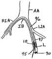
통상적 환자 준비에 이어, 우측 공통 대퇴 동맥이 절개 또는 셀딩거(Seldinger) 기술을 통해 억세스되고, 가이드 와이어(80)가 하부 복부 대동맥(AA)에 도달할 때까지 우측 장골 동맥(RIA)을 통해 전진된다. 그후, 관찰 카테터(50)가 도 12A에 도시된 바와 같이 원위 단부가 장골 분기부(IB)를 통과할 때까지 가이드 와이어(80)를 따라 전진된다.Following conventional patient preparation, the right common femoral artery is accessed through an incision or Seldinger technique and advances through the right iliac artery (RIA) until the
원위 단부(52)가 예를 들어, 형광투시 관찰을 사용하여 방사선 불투과성 마커의 위치에 의해 결정되는 바와 같이 장골 분기부 부근에 배치되고 나면, 가이드 와이어(80)가 원위 단부(52) 내로 수축된다. 그후, 도 12B에 도시된 바와 같이 출구(64)가 좌측 장골 동맥 내로 지향되도록 당김 와이어(56)가 원위 단부(52)를 편향시키도록 레버(58)가 근위방향으로 수축된다. 가이드 와이어(80)는 환자의 좌측 장골 동맥 내로 전진되고, 레버(58)가 해제되며, 형광투시 관찰을 사용하여 결정될 수 있는 바와 같이, 관찰 카테터가 가이드 와이어를 따라 좌측 SFA 내로 테이퍼부(54)가 병소(L)를 가로지를 때까지 전진된다.Once the distal end 52 has been placed near the iliac bifurcation, as determined by the location of the radiopaque marker, for example using fluoroscopy, the
테이퍼부(54)가 병소를 가로질러 배치될 때, 의사는 도 12C에 도시된 바와 같이 원위 단부(52) 내의 출구(62)를 통해 조영제가 배출되도록 조영제 주입 포트(59)를 통해 조영제(CA)를 주입한다. 이 방식으로, 조영제(CA)는 최소의 희석으로 치료 부위로 직접 전달될 수 있으며, 그에 의해, 병소 지형의 보다 양호한 영상을 제공한다.When the tapered
그후, 공지된 관찰 기술이 사용되어 예로서, 병소의 크기를 알려진 방사선 불투과성 마커(55)의 치수와 비교함으로써 병소의 위치 및 범위를 측정할 수 있다. 그후, 의사는 적절한 크기의 혈관 보철 및 전달 카테터를 선택하기 위해 이 정보를 사용한다. 병소의 위치 및 크기가 확정되고 나면, 가이드 와이어(80)는 필터-팁형 가이드 와이어(90)로 교체되고, 그후, 관찰 카테터(50)가 인출된다.Then, known observation techniques can be used to determine the location and extent of the lesion, for example, by comparing the size of the lesion with the dimensions of the known
의사가 적절한 전달 카테터 및 혈관 보철(10)을 선택한 이후, 전달 카테터 및 혈관 보철은 스텐트가 병소를 가로질러 배치될 때까지 필터 팁형 가이드 와이어를 따라 전진된다. 도 12D에서, 혈관 보철(10)은 전달 카테터(96)의 벌룬(95)상에서 완전히 절첩된 구조로 배치되어 있다. 예시적으로, 전달 카테터는 외피(97)를 포함할 수도 있지만, 외피는 생략될 수 있다. 그후, 혈관 보철(10)이 병소를 가로질러 배치될 때까지 전달 카테터가 가이드 와이어(90)를 따라 전진되고, 그후, 외피(97)가 근위방향으로 수축되어 도 12D에 도시된 바와 같이 혈관 보철(10)을 노출시킨다.After the physician selects the appropriate delivery catheter and
그후, 벌룬(95)이 팽창되어 혈관 보철(10)을 도 12E에 도시된 바와 같이 완전히 팽창된 전개된 구조로 전이시킨다. 벌룬이 팽창할 때, 이는 유닛 셀의 얇은 스트러트 내의 힘이 혈관 보철(10)의 셀이 완전히 팽창된 전개된 구조로 "스냅"되는 지점인 Fmax에 도달할 때까지 혈관 보철의 내부면에 반경방향 외향 지향력을 인가한다. 이 방식으로 혈관 보철(10)은 과팽창 또는 되감김없이 혈관의 벽과 결합하고, 그에 의해, 이전에 알려진 소성 변형가능한 스텐트의 전달과 연계된 상처를 피한다.Thereafter,
혈관 보철(10)이 전개되고 나면, 벌룬(85)이 수축되고, 예로서, 혈관 보철 내에 통합된 방사선 불투과성 마커(47)를 사용하여 혈관 보철의 위치를 확인하기 위해 종래의 이미징 기술이 사용될 수 있다. 그후, 전달 카테터(96)가 제거되고, 그후, 역시 필터 팁형 가이드 와이어(90)가 인출되어 도 12F에 도시된 바와 같이, 좌측 SFA 내에 전개된 혈관 보철(10)을 남기게 된다.Once the
비록, 본 발명의 양호한 예시적 실시예를 상술하였지만, 당업자들은 본 발명으로부터 벗어나지 않고 다양한 변경 및 변용이 이루어질 수 있다는 것을 명확히 알 수 있을 것이다. 본 발명의 진정한 개념 및 범주 내에 드는 모든 이런 변경 및 변용은 첨부된 청구범위에 포함된다.Although the preferred exemplary embodiments of the invention have been described above, those skilled in the art will clearly appreciate that various changes and modifications can be made without departing from the invention. All such changes and modifications that fall within the true spirit and scope of the present invention are included in the appended claims.
Claims (25)
Translated fromKoreanApplications Claiming Priority (3)
| Application Number | Priority Date | Filing Date | Title |
|---|---|---|---|
| US11/391,940US8353948B2 (en) | 1997-01-24 | 2006-03-29 | Fracture-resistant helical stent incorporating bistable cells and methods of use |
| US11/391,940 | 2006-03-29 | ||
| PCT/US2007/007377WO2007126729A2 (en) | 2006-03-29 | 2007-03-23 | Fracture-resistant helical stent incorporating bistable cells and methods of use |
Publications (2)
| Publication Number | Publication Date |
|---|---|
| KR20090005069A KR20090005069A (en) | 2009-01-12 |
| KR101365548B1true KR101365548B1 (en) | 2014-02-20 |
Family
ID=38655994
Family Applications (1)
| Application Number | Title | Priority Date | Filing Date |
|---|---|---|---|
| KR1020087026197AExpired - Fee RelatedKR101365548B1 (en) | 2006-03-29 | 2007-03-23 | Fracture-resistant helical stent incorporating bistable cells and methods of use |
Country Status (10)
| Country | Link |
|---|---|
| US (1) | US8353948B2 (en) |
| EP (1) | EP1998714B1 (en) |
| JP (3) | JP2009531135A (en) |
| KR (1) | KR101365548B1 (en) |
| CN (2) | CN102232884B (en) |
| AU (1) | AU2007243708B2 (en) |
| CA (1) | CA2647305C (en) |
| ES (1) | ES2524336T3 (en) |
| RU (1) | RU2008138267A (en) |
| WO (1) | WO2007126729A2 (en) |
Families Citing this family (62)
| Publication number | Priority date | Publication date | Assignee | Title |
|---|---|---|---|---|
| US8663311B2 (en)* | 1997-01-24 | 2014-03-04 | Celonova Stent, Inc. | Device comprising biodegradable bistable or multistable cells and methods of use |
| ATE306873T1 (en)* | 1997-01-24 | 2005-11-15 | Kentucky Oil N V | BISTABLE SPRING STRUCTURE FOR A STENT |
| JP3382885B2 (en) | 1999-06-02 | 2003-03-04 | 山口日本電気株式会社 | Ion implantation apparatus and ion implantation method |
| US6799637B2 (en) | 2000-10-20 | 2004-10-05 | Schlumberger Technology Corporation | Expandable tubing and method |
| NO335594B1 (en) | 2001-01-16 | 2015-01-12 | Halliburton Energy Serv Inc | Expandable devices and methods thereof |
| DE10154163A1 (en) | 2001-11-03 | 2003-05-22 | Advanced Med Tech | Device for straightening and stabilizing the spine |
| CA2857815C (en)* | 2005-12-30 | 2016-10-11 | C.R. Bard Inc. | Stent with bio-resorbable connector and methods |
| US8277501B2 (en)* | 2007-12-21 | 2012-10-02 | Boston Scientific Scimed, Inc. | Bi-stable bifurcated stent petal geometry |
| GB0804654D0 (en) | 2008-03-13 | 2008-04-16 | Smith & Nephew | Vacuum closure device |
| WO2010014510A1 (en)* | 2008-07-31 | 2010-02-04 | Boston Scientific Scimed, Inc. | Coils for vascular implants or other uses |
| CN102292053A (en) | 2008-09-29 | 2011-12-21 | 卡迪尔克阀门技术公司 | Heart valve |
| WO2010040009A1 (en) | 2008-10-01 | 2010-04-08 | Cardiaq Valve Technologies, Inc. | Delivery system for vascular implant |
| US9539120B2 (en)* | 2008-10-10 | 2017-01-10 | Veryan Medical Ltd. | Medical device suitable for location in a body lumen |
| JP2012505003A (en)* | 2008-10-10 | 2012-03-01 | ヴェリヤン・メディカル・リミテッド | Medical devices suitable for placement in body cavities |
| KR101085014B1 (en)* | 2009-02-27 | 2011-11-21 | 연세대학교 산학협력단 | Optical surface measuring device and method |
| CA2961053C (en) | 2009-04-15 | 2019-04-30 | Edwards Lifesciences Cardiaq Llc | Vascular implant and delivery system |
| US10456276B2 (en)* | 2009-05-08 | 2019-10-29 | Veryan Medical Limited | Medical device suitable for location in a body lumen |
| EP2456481B1 (en)* | 2009-07-24 | 2016-11-23 | Boston Scientific Scimed, Inc. | Medical devices having an inorganic coating layer formed by atomic layer deposition |
| US20110066223A1 (en)* | 2009-09-14 | 2011-03-17 | Hossainy Syed F A | Bioabsorbable Stent With Time Dependent Structure And Properties |
| US8425587B2 (en) | 2009-09-17 | 2013-04-23 | Abbott Cardiovascular Systems Inc. | Method of treatment with a bioabsorbable stent with time dependent structure and properties and regio-selective degradation |
| KR101137896B1 (en)* | 2009-11-12 | 2012-05-02 | 연세대학교 산학협력단 | Branch Vessel Protection Stent on Branch Lesions |
| US8579964B2 (en) | 2010-05-05 | 2013-11-12 | Neovasc Inc. | Transcatheter mitral valve prosthesis |
| US9421132B2 (en) | 2011-02-04 | 2016-08-23 | University Of Massachusetts | Negative pressure wound closure device |
| US9308087B2 (en) | 2011-04-28 | 2016-04-12 | Neovasc Tiara Inc. | Sequentially deployed transcatheter mitral valve prosthesis |
| US9554897B2 (en) | 2011-04-28 | 2017-01-31 | Neovasc Tiara Inc. | Methods and apparatus for engaging a valve prosthesis with tissue |
| US9254212B2 (en) | 2012-04-06 | 2016-02-09 | Abbott Cardiovascular Systems Inc. | Segmented scaffolds and delivery thereof for peripheral applications |
| EP2852419B1 (en) | 2012-05-22 | 2019-11-20 | Smith & Nephew plc | Wound closure device |
| EP2852333B1 (en) | 2012-05-22 | 2021-12-15 | Smith & Nephew plc | Apparatuses for wound therapy |
| AU2013264937B2 (en) | 2012-05-24 | 2018-04-19 | Smith & Nephew Inc. | Devices and methods for treating and closing wounds with negative pressure |
| US9345573B2 (en) | 2012-05-30 | 2016-05-24 | Neovasc Tiara Inc. | Methods and apparatus for loading a prosthesis onto a delivery system |
| MX369689B (en) | 2012-07-16 | 2019-11-19 | Smith & Nephew Inc | Negative pressure wound closure device. |
| US8834556B2 (en) | 2012-08-13 | 2014-09-16 | Abbott Cardiovascular Systems Inc. | Segmented scaffold designs |
| US10583002B2 (en) | 2013-03-11 | 2020-03-10 | Neovasc Tiara Inc. | Prosthetic valve with anti-pivoting mechanism |
| US10124098B2 (en) | 2013-03-13 | 2018-11-13 | Smith & Nephew, Inc. | Negative pressure wound closure device and systems and methods of use in treating wounds with negative pressure |
| BR112015021123A2 (en) | 2013-03-14 | 2017-07-18 | Smith & Nephew | compressible wound fillers and systems and methods for use in treating negative pressure injuries |
| US9681951B2 (en) | 2013-03-14 | 2017-06-20 | Edwards Lifesciences Cardiaq Llc | Prosthesis with outer skirt and anchors |
| US9572665B2 (en) | 2013-04-04 | 2017-02-21 | Neovasc Tiara Inc. | Methods and apparatus for delivering a prosthetic valve to a beating heart |
| CA2918157A1 (en) | 2013-07-16 | 2015-01-22 | Smith & Nephew Plc | Apparatus for wound therapy |
| US9717609B2 (en) | 2013-08-01 | 2017-08-01 | Abbott Cardiovascular Systems Inc. | Variable stiffness stent |
| CN106170275B (en) | 2013-10-21 | 2021-05-07 | 史密夫和内修有限公司 | Negative pressure wound closure device |
| AU2015208299B2 (en) | 2014-01-21 | 2019-11-21 | Smith & Nephew Plc | Collapsible dressing for negative pressure wound treatment |
| EP3096725B1 (en) | 2014-01-21 | 2023-10-18 | Smith & Nephew plc | Wound treatment apparatuses |
| US11223919B2 (en) | 2014-12-01 | 2022-01-11 | Staton Techiya, Llc | Fixation methods for traversing ear canals |
| US20210322223A1 (en)* | 2014-12-01 | 2021-10-21 | Staton Techiya Llc | Fixation methods for devices in tubular structures |
| AU2016254119A1 (en) | 2015-04-29 | 2017-10-05 | Smith & Nephew Inc. | Negative pressure wound closure device |
| DE102015111019B4 (en)* | 2015-07-08 | 2021-02-18 | Acandis Gmbh | Medical device for endovascular treatment |
| US11471586B2 (en) | 2015-12-15 | 2022-10-18 | University Of Massachusetts | Negative pressure wound closure devices and methods |
| CA2961625A1 (en)* | 2016-06-02 | 2017-12-02 | The Royal Institution For The Advancement Of Learning/Mcgill University | Bistable auxetics |
| JP7038701B2 (en) | 2016-08-30 | 2022-03-18 | スミス アンド ネフュー ピーエルシー | System for applying decompression therapy |
| US11096832B2 (en) | 2016-09-27 | 2021-08-24 | Smith & Nephew Plc | Wound closure devices with dissolvable portions |
| CN110167495B (en) | 2016-11-02 | 2022-06-14 | 史密夫和内修有限公司 | Wound closure device |
| US10966849B2 (en) | 2017-03-08 | 2021-04-06 | Yamaguchi University | Indwelling medical device having bistable structure in lumen organ |
| WO2018229009A1 (en)* | 2017-06-13 | 2018-12-20 | Smith & Nephew Plc | Wound closure device and method of use |
| EP3638169B1 (en) | 2017-06-13 | 2024-11-13 | Smith & Nephew PLC | Collapsible structure and method of use |
| US11123476B2 (en) | 2017-06-14 | 2021-09-21 | Smith & Nephew, Inc. | Fluid removal management and control of wound closure in wound therapy |
| WO2018231874A1 (en) | 2017-06-14 | 2018-12-20 | Smith & Nephew, Inc. | Control of wound closure and fluid removal management in wound therapy |
| WO2018229011A1 (en) | 2017-06-14 | 2018-12-20 | Smith & Nephew Plc | Collapsible structure for wound closure and method of use |
| AU2018285239B2 (en) | 2017-06-14 | 2023-09-21 | Smith & Nephew Plc | Collapsible sheet for wound closure and method of use |
| WO2019020544A1 (en) | 2017-07-27 | 2019-01-31 | Smith & Nephew Plc | Customizable wound closure device and method of use |
| US11590030B2 (en) | 2017-08-07 | 2023-02-28 | Smith & Nephew Plc | Wound closure device with protective layer and method of use |
| EP3675925A1 (en) | 2017-08-29 | 2020-07-08 | Smith & Nephew PLC | Systems and methods for monitoring wound closure |
| US10932927B2 (en)* | 2018-08-29 | 2021-03-02 | DePuy Synthes Products, Inc. | Stent with longitudinal variable width struts |
Citations (4)
| Publication number | Priority date | Publication date | Assignee | Title |
|---|---|---|---|---|
| US5725572A (en) | 1994-04-25 | 1998-03-10 | Advanced Cardiovascular Systems, Inc. | Radiopaque stent |
| US5899882A (en) | 1994-10-27 | 1999-05-04 | Novoste Corporation | Catheter apparatus for radiation treatment of a desired area in the vascular system of a patient |
| US5913897A (en) | 1993-09-16 | 1999-06-22 | Cordis Corporation | Endoprosthesis having multiple bridging junctions and procedure |
| US5922020A (en) | 1996-08-02 | 1999-07-13 | Localmed, Inc. | Tubular prosthesis having improved expansion and imaging characteristics |
Family Cites Families (124)
| Publication number | Priority date | Publication date | Assignee | Title |
|---|---|---|---|---|
| US3069125A (en)* | 1958-01-20 | 1962-12-18 | Robertshaw Fulton Controls Co | Heat actuated snap acting valve |
| US3508587A (en)* | 1966-09-29 | 1970-04-28 | Hans A Mauch | Tubular structural member |
| US3657744A (en) | 1970-05-08 | 1972-04-25 | Univ Minnesota | Method for fixing prosthetic implants in a living body |
| CH543400A (en) | 1972-10-10 | 1973-10-31 | Peyer Siegfried | Clamping device for office papers |
| US5643314A (en)* | 1995-11-13 | 1997-07-01 | Navius Corporation | Self-expanding stent |
| FR2487086A1 (en) | 1980-07-18 | 1982-01-22 | Albertini Prosper | METHOD AND DEVICES FOR PLACING AND MAINTAINING A RIBBON IN A GLASSES ENHASSURE FOR OBTAINING A TEMPLATE BY CASTING |
| SE445884B (en)* | 1982-04-30 | 1986-07-28 | Medinvent Sa | DEVICE FOR IMPLANTATION OF A RODFORM PROTECTION |
| US4665906A (en)* | 1983-10-14 | 1987-05-19 | Raychem Corporation | Medical devices incorporating sim alloy elements |
| US4580568A (en)* | 1984-10-01 | 1986-04-08 | Cook, Incorporated | Percutaneous endovascular stent and method for insertion thereof |
| GB8432814D0 (en) | 1984-12-31 | 1985-02-06 | Lifeline Ltd | Catheter mount assembly |
| GB2175824A (en) | 1985-05-29 | 1986-12-10 | Barry Rene Christopher Paul | Producing composite metal articles |
| US4641654A (en)* | 1985-07-30 | 1987-02-10 | Advanced Cardiovascular Systems, Inc. | Steerable balloon dilatation catheter assembly having dye injection and pressure measurement capabilities |
| US4733665C2 (en)* | 1985-11-07 | 2002-01-29 | Expandable Grafts Partnership | Expandable intraluminal graft and method and apparatus for implanting an expandable intraluminal graft |
| US5102417A (en)* | 1985-11-07 | 1992-04-07 | Expandable Grafts Partnership | Expandable intraluminal graft, and method and apparatus for implanting an expandable intraluminal graft |
| US4665918A (en)* | 1986-01-06 | 1987-05-19 | Garza Gilbert A | Prosthesis system and method |
| US4740207A (en)* | 1986-09-10 | 1988-04-26 | Kreamer Jeffry W | Intralumenal graft |
| US4893623A (en) | 1986-12-09 | 1990-01-16 | Advanced Surgical Intervention, Inc. | Method and apparatus for treating hypertrophy of the prostate gland |
| JPH088933B2 (en) | 1987-07-10 | 1996-01-31 | 日本ゼオン株式会社 | Catheter |
| US4886062A (en) | 1987-10-19 | 1989-12-12 | Medtronic, Inc. | Intravascular radially expandable stent and method of implant |
| US5192307A (en) | 1987-12-08 | 1993-03-09 | Wall W Henry | Angioplasty stent |
| JP2561853B2 (en)* | 1988-01-28 | 1996-12-11 | 株式会社ジェイ・エム・エス | Shaped memory molded article and method of using the same |
| US4886061A (en)* | 1988-02-09 | 1989-12-12 | Medinnovations, Inc. | Expandable pullback atherectomy catheter system |
| US5226913A (en)* | 1988-09-01 | 1993-07-13 | Corvita Corporation | Method of making a radially expandable prosthesis |
| CA1322628C (en) | 1988-10-04 | 1993-10-05 | Richard A. Schatz | Expandable intraluminal graft |
| DE8812719U1 (en) | 1988-10-11 | 1989-11-09 | Lindenberg, Josef, 7500 Karlsruhe | Device for correcting stenosis |
| FR2642812B1 (en) | 1989-02-08 | 1991-05-31 | Crouzet Sa | PIEZOELECTRIC OPTICALLY CONTROLLED FLUID SWITCHING DEVICE |
| US5114423A (en)* | 1989-05-15 | 1992-05-19 | Advanced Cardiovascular Systems, Inc. | Dilatation catheter assembly with heated balloon |
| US4990155A (en)* | 1989-05-19 | 1991-02-05 | Wilkoff Howard M | Surgical stent method and apparatus |
| US4994071A (en)* | 1989-05-22 | 1991-02-19 | Cordis Corporation | Bifurcating stent apparatus and method |
| US5141360A (en)* | 1989-09-18 | 1992-08-25 | David Zeman | Irrigation tubing |
| IE73670B1 (en) | 1989-10-02 | 1997-07-02 | Medtronic Inc | Articulated stent |
| US5545208A (en)* | 1990-02-28 | 1996-08-13 | Medtronic, Inc. | Intralumenal drug eluting prosthesis |
| DE9014230U1 (en) | 1990-10-13 | 1991-11-21 | Angiomed AG, 7500 Karlsruhe | Device for dilating a stenosis in a body tube |
| US5330500A (en) | 1990-10-18 | 1994-07-19 | Song Ho Y | Self-expanding endovascular stent with silicone coating |
| US5197978B1 (en)* | 1991-04-26 | 1996-05-28 | Advanced Coronary Tech | Removable heat-recoverable tissue supporting device |
| US5147370A (en) | 1991-06-12 | 1992-09-15 | Mcnamara Thomas O | Nitinol stent for hollow body conduits |
| US5500013A (en)* | 1991-10-04 | 1996-03-19 | Scimed Life Systems, Inc. | Biodegradable drug delivery vascular stent |
| CA2079417C (en) | 1991-10-28 | 2003-01-07 | Lilip Lau | Expandable stents and method of making same |
| FR2683449A1 (en)* | 1991-11-08 | 1993-05-14 | Cardon Alain | ENDOPROTHESIS FOR TRANSLUMINAL IMPLANTATION. |
| US5234448A (en)* | 1992-02-28 | 1993-08-10 | Shadyside Hospital | Method and apparatus for connecting and closing severed blood vessels |
| US5282823A (en)* | 1992-03-19 | 1994-02-01 | Medtronic, Inc. | Intravascular radially expandable stent |
| US5540712A (en) | 1992-05-01 | 1996-07-30 | Nitinol Medical Technologies, Inc. | Stent and method and apparatus for forming and delivering the same |
| EP0639958A1 (en) | 1992-05-08 | 1995-03-01 | Schneider (Usa) Inc. | Esophageal stent and delivery tool |
| US5476434A (en) | 1992-05-27 | 1995-12-19 | Kalb; Irvin M. | Female incontinence device including electronic sensors |
| US5496365A (en)* | 1992-07-02 | 1996-03-05 | Sgro; Jean-Claude | Autoexpandable vascular endoprosthesis |
| US6336938B1 (en)* | 1992-08-06 | 2002-01-08 | William Cook Europe A/S | Implantable self expanding prosthetic device |
| DE69308568T2 (en) | 1992-08-06 | 1997-10-02 | Cook William Europ | PROSTHESIS FOR SUPPORTING A BLOOD VESSEL OR A LUMEN OF A CAVE ORGAN |
| US5383926A (en)* | 1992-11-23 | 1995-01-24 | Children's Medical Center Corporation | Re-expandable endoprosthesis |
| BE1006440A3 (en)* | 1992-12-21 | 1994-08-30 | Dereume Jean Pierre Georges Em | Luminal endoprosthesis AND METHOD OF PREPARATION. |
| DE4300285A1 (en) | 1993-01-08 | 1994-07-14 | Wolf Gmbh Richard | Instrument for implanting and extracting stents |
| WO1994016646A1 (en) | 1993-01-19 | 1994-08-04 | Schneider (Usa) Inc. | Clad composite stent |
| CA2127637C (en) | 1993-07-26 | 2006-01-03 | Scott Bair | Fluid jet surgical cutting tool |
| FR2710834B1 (en)* | 1993-10-05 | 1995-12-22 | Guerbet Sa | Expandable tubular organ for intraluminal endoprosthesis, intraluminal endoprosthesis, manufacturing process. |
| US5562690A (en)* | 1993-11-12 | 1996-10-08 | United States Surgical Corporation | Apparatus and method for performing compressional anastomoses |
| IT1269443B (en)* | 1994-01-19 | 1997-04-01 | Stefano Nazari | VASCULAR PROSTHESIS FOR THE REPLACEMENT OR INTERNAL COATING OF MEDIUM AND LARGE DIAMETER BLOOD VESSELS AND DEVICE FOR ITS APPLICATION WITHOUT INTERRUPTION OF BLOOD FLOW |
| US5403341A (en) | 1994-01-24 | 1995-04-04 | Solar; Ronald J. | Parallel flow endovascular stent and deployment apparatus therefore |
| US5556413A (en) | 1994-03-11 | 1996-09-17 | Advanced Cardiovascular Systems, Inc. | Coiled stent with locking ends |
| US5733303A (en) | 1994-03-17 | 1998-03-31 | Medinol Ltd. | Flexible expandable stent |
| US5449373A (en)* | 1994-03-17 | 1995-09-12 | Medinol Ltd. | Articulated stent |
| DE69507800T2 (en)* | 1994-05-19 | 1999-07-22 | Scimed Life Systems, Inc., Maple Grove, Minn. | IMPROVED TISSUE SUPPORTS |
| DE69528216T2 (en)* | 1994-06-17 | 2003-04-17 | Terumo K.K., Tokio/Tokyo | Process for the production of a permanent stent |
| DE69530891T2 (en) | 1994-06-27 | 2004-05-13 | Corvita Corp., Miami | Bistable luminal graft endoprostheses |
| US5397355A (en) | 1994-07-19 | 1995-03-14 | Stentco, Inc. | Intraluminal stent |
| US5702419A (en)* | 1994-09-21 | 1997-12-30 | Wake Forest University | Expandable, intraluminal stents |
| US5545210A (en)* | 1994-09-22 | 1996-08-13 | Advanced Coronary Technology, Inc. | Method of implanting a permanent shape memory alloy stent |
| US5683345A (en)* | 1994-10-27 | 1997-11-04 | Novoste Corporation | Method and apparatus for treating a desired area in the vascular system of a patient |
| DE19508805C2 (en)* | 1995-03-06 | 2000-03-30 | Lutz Freitag | Stent for placement in a body tube with a flexible support structure made of at least two wires with different shape memory functions |
| GB9505721D0 (en) | 1995-03-21 | 1995-05-10 | Univ London | Expandable surgical stent |
| ES2119527T5 (en)* | 1995-04-01 | 2006-11-16 | Variomed Ag | STENT DEVICE FOR TRANSLUMINAL IMPLEMENTATION IN HOLLOW ORGANS. |
| US6602281B1 (en)* | 1995-06-05 | 2003-08-05 | Avantec Vascular Corporation | Radially expansible vessel scaffold having beams and expansion joints |
| RU2157146C2 (en) | 1995-06-13 | 2000-10-10 | ВИЛЬЯМ КУК Европа, A/S | Device for performing implantation in blood vessels and hollow organs |
| IL123039A (en) | 1995-07-25 | 2002-02-10 | Medstent Inc | Expandible stent |
| DK171865B1 (en)* | 1995-09-11 | 1997-07-21 | Cook William Europ | Expandable endovascular stent |
| US5824040A (en)* | 1995-12-01 | 1998-10-20 | Medtronic, Inc. | Endoluminal prostheses and therapies for highly variable body lumens |
| US6203569B1 (en)* | 1996-01-04 | 2001-03-20 | Bandula Wijay | Flexible stent |
| US5895406A (en)* | 1996-01-26 | 1999-04-20 | Cordis Corporation | Axially flexible stent |
| US5695516A (en)* | 1996-02-21 | 1997-12-09 | Iso Stent, Inc. | Longitudinally elongating balloon expandable stent |
| NZ331269A (en)* | 1996-04-10 | 2000-01-28 | Advanced Cardiovascular System | Expandable stent, its structural strength varying along its length |
| US5891191A (en) | 1996-04-30 | 1999-04-06 | Schneider (Usa) Inc | Cobalt-chromium-molybdenum alloy stent and stent-graft |
| US5697971A (en)* | 1996-06-11 | 1997-12-16 | Fischell; Robert E. | Multi-cell stent with cells having differing characteristics |
| US5776183A (en)* | 1996-08-23 | 1998-07-07 | Kanesaka; Nozomu | Expandable stent |
| US5807404A (en)* | 1996-09-19 | 1998-09-15 | Medinol Ltd. | Stent with variable features to optimize support and method of making such stent |
| US5755776A (en)* | 1996-10-04 | 1998-05-26 | Al-Saadon; Khalid | Permanent expandable intraluminal tubular stent |
| US5700303A (en)* | 1996-10-31 | 1997-12-23 | Zander; Richard A. | Chrome polish/exhaust pipe de-bluer |
| US6027527A (en)* | 1996-12-06 | 2000-02-22 | Piolax Inc. | Stent |
| US6206911B1 (en)* | 1996-12-19 | 2001-03-27 | Simcha Milo | Stent combination |
| ATE306873T1 (en)* | 1997-01-24 | 2005-11-15 | Kentucky Oil N V | BISTABLE SPRING STRUCTURE FOR A STENT |
| US8663311B2 (en)* | 1997-01-24 | 2014-03-04 | Celonova Stent, Inc. | Device comprising biodegradable bistable or multistable cells and methods of use |
| DE19703482A1 (en)* | 1997-01-31 | 1998-08-06 | Ernst Peter Prof Dr M Strecker | Stent |
| US5827321A (en)* | 1997-02-07 | 1998-10-27 | Cornerstone Devices, Inc. | Non-Foreshortening intraluminal prosthesis |
| JP4292710B2 (en)* | 1997-09-24 | 2009-07-08 | エム イー ディ インスチィチュート インク | Radially expandable stent |
| US6042606A (en)* | 1997-09-29 | 2000-03-28 | Cook Incorporated | Radially expandable non-axially contracting surgical stent |
| US6623521B2 (en)* | 1998-02-17 | 2003-09-23 | Md3, Inc. | Expandable stent with sliding and locking radial elements |
| US6019789A (en)* | 1998-04-01 | 2000-02-01 | Quanam Medical Corporation | Expandable unit cell and intraluminal stent |
| US6093203A (en)* | 1998-05-13 | 2000-07-25 | Uflacker; Renan | Stent or graft support structure for treating bifurcated vessels having different diameter portions and methods of use and implantation |
| US6261319B1 (en)* | 1998-07-08 | 2001-07-17 | Scimed Life Systems, Inc. | Stent |
| US6152943A (en)* | 1998-08-14 | 2000-11-28 | Incept Llc | Methods and apparatus for intraluminal deposition of hydrogels |
| US6755856B2 (en) | 1998-09-05 | 2004-06-29 | Abbott Laboratories Vascular Enterprises Limited | Methods and apparatus for stenting comprising enhanced embolic protection, coupled with improved protection against restenosis and thrombus formation |
| US6193744B1 (en)* | 1998-09-10 | 2001-02-27 | Scimed Life Systems, Inc. | Stent configurations |
| US6355059B1 (en)* | 1998-12-03 | 2002-03-12 | Medinol, Ltd. | Serpentine coiled ladder stent |
| US6264685B1 (en)* | 1999-07-06 | 2001-07-24 | Datascope Investment Corp. | Flexible high radial strength stent |
| AU1084101A (en)* | 1999-10-14 | 2001-04-23 | United Stenting, Inc. | Stents with multilayered struts |
| WO2001035715A2 (en) | 1999-11-18 | 2001-05-25 | Petrus Besselink | Method for placing bifurcated stents |
| AU782484B2 (en)* | 1999-12-02 | 2005-08-04 | Edwards Lifesciences Corporation | Methods and apparatus for delivering medicament to tissue |
| US6423091B1 (en)* | 2000-05-16 | 2002-07-23 | Cordis Corporation | Helical stent having flat ends |
| US6799637B2 (en) | 2000-10-20 | 2004-10-05 | Schlumberger Technology Corporation | Expandable tubing and method |
| JP3778786B2 (en)* | 2000-08-04 | 2006-05-24 | 日本ライフライン株式会社 | Stent |
| GB2371066B8 (en)* | 2001-01-16 | 2012-12-19 | Halliburton Energy Serv Inc | Tubulars with expandable cells and locking mechanisms |
| US6540777B2 (en)* | 2001-02-15 | 2003-04-01 | Scimed Life Systems, Inc. | Locking stent |
| JP2002272855A (en)* | 2001-03-14 | 2002-09-24 | Piolax Medical Device:Kk | Stent |
| US20040133270A1 (en) | 2002-07-08 | 2004-07-08 | Axel Grandt | Drug eluting stent and methods of manufacture |
| DE10233085B4 (en)* | 2002-07-19 | 2014-02-20 | Dendron Gmbh | Stent with guide wire |
| US6969402B2 (en)* | 2002-07-26 | 2005-11-29 | Syntheon, Llc | Helical stent having flexible transition zone |
| US20050163821A1 (en) | 2002-08-02 | 2005-07-28 | Hsing-Wen Sung | Drug-eluting Biodegradable Stent and Delivery Means |
| EP1534184B1 (en) | 2002-08-07 | 2014-07-02 | CeloNova Stent, Inc. | Apparatus for a stent or other medical device having a bistable spring construction |
| DE10237572A1 (en)* | 2002-08-13 | 2004-02-26 | Biotronik Meß- und Therapiegeräte GmbH & Co. Ingenieurbüro Berlin | Stent with a polymer coating |
| JP4481559B2 (en)* | 2002-09-30 | 2010-06-16 | テルモ株式会社 | Stent for living indwelling and organ expansion device |
| US7527632B2 (en)* | 2003-03-31 | 2009-05-05 | Cordis Corporation | Modified delivery device for coated medical devices |
| US20050055080A1 (en)* | 2003-09-05 | 2005-03-10 | Naim Istephanous | Modulated stents and methods of making the stents |
| US20050182479A1 (en)* | 2004-02-13 | 2005-08-18 | Craig Bonsignore | Connector members for stents |
| JP4542360B2 (en)* | 2004-03-30 | 2010-09-15 | テルモ株式会社 | Self-expanding in-vivo stent |
| US7291166B2 (en)* | 2005-05-18 | 2007-11-06 | Advanced Cardiovascular Systems, Inc. | Polymeric stent patterns |
| US7476245B2 (en)* | 2005-08-16 | 2009-01-13 | Advanced Cardiovascular Systems, Inc. | Polymeric stent patterns |
| EP3669830A1 (en)* | 2006-10-21 | 2020-06-24 | CeloNova Stent, Inc. | Deformable lumen support devices and methods of use |
- 2006
- 2006-03-29USUS11/391,940patent/US8353948B2/ennot_activeExpired - Fee Related
- 2007
- 2007-03-23CNCN201110152706.6Apatent/CN102232884B/ennot_activeExpired - Fee Related
- 2007-03-23CACA2647305Apatent/CA2647305C/enactiveActive
- 2007-03-23WOPCT/US2007/007377patent/WO2007126729A2/enactiveApplication Filing
- 2007-03-23RURU2008138267/14Apatent/RU2008138267A/enunknown
- 2007-03-23CNCN2007800155509Apatent/CN101431964B/ennot_activeExpired - Fee Related
- 2007-03-23ESES07753961.7Tpatent/ES2524336T3/enactiveActive
- 2007-03-23AUAU2007243708Apatent/AU2007243708B2/ennot_activeCeased
- 2007-03-23EPEP07753961.7Apatent/EP1998714B1/ennot_activeNot-in-force
- 2007-03-23KRKR1020087026197Apatent/KR101365548B1/ennot_activeExpired - Fee Related
- 2007-03-23JPJP2009502907Apatent/JP2009531135A/ennot_activeWithdrawn
- 2014
- 2014-07-25JPJP2014151979Apatent/JP5960204B2/ennot_activeExpired - Fee Related
- 2015
- 2015-09-24JPJP2015186601Apatent/JP6105697B2/ennot_activeExpired - Fee Related
Patent Citations (4)
| Publication number | Priority date | Publication date | Assignee | Title |
|---|---|---|---|---|
| US5913897A (en) | 1993-09-16 | 1999-06-22 | Cordis Corporation | Endoprosthesis having multiple bridging junctions and procedure |
| US5725572A (en) | 1994-04-25 | 1998-03-10 | Advanced Cardiovascular Systems, Inc. | Radiopaque stent |
| US5899882A (en) | 1994-10-27 | 1999-05-04 | Novoste Corporation | Catheter apparatus for radiation treatment of a desired area in the vascular system of a patient |
| US5922020A (en) | 1996-08-02 | 1999-07-13 | Localmed, Inc. | Tubular prosthesis having improved expansion and imaging characteristics |
Also Published As
| Publication number | Publication date |
|---|---|
| JP2016019765A (en) | 2016-02-04 |
| WO2007126729A2 (en) | 2007-11-08 |
| KR20090005069A (en) | 2009-01-12 |
| ES2524336T3 (en) | 2014-12-05 |
| JP6105697B2 (en) | 2017-03-29 |
| AU2007243708A1 (en) | 2007-11-08 |
| US20060217795A1 (en) | 2006-09-28 |
| JP2014239914A (en) | 2014-12-25 |
| EP1998714A2 (en) | 2008-12-10 |
| CN101431964B (en) | 2011-08-03 |
| AU2007243708A2 (en) | 2009-02-12 |
| CA2647305C (en) | 2012-01-03 |
| CN102232884B (en) | 2015-04-08 |
| JP2009531135A (en) | 2009-09-03 |
| US8353948B2 (en) | 2013-01-15 |
| CN102232884A (en) | 2011-11-09 |
| CA2647305A1 (en) | 2007-11-08 |
| EP1998714B1 (en) | 2014-11-05 |
| RU2008138267A (en) | 2010-05-10 |
| WO2007126729A3 (en) | 2008-11-20 |
| AU2007243708B2 (en) | 2013-12-19 |
| CN101431964A (en) | 2009-05-13 |
| EP1998714A4 (en) | 2013-01-09 |
| JP5960204B2 (en) | 2016-08-02 |
Similar Documents
| Publication | Publication Date | Title |
|---|---|---|
| KR101365548B1 (en) | Fracture-resistant helical stent incorporating bistable cells and methods of use | |
| JP5042578B2 (en) | Intraluminal medical devices stacked and interconnected | |
| JP5259746B2 (en) | Lumen prosthesis | |
| US8920488B2 (en) | Endoprosthesis having a stable architecture | |
| DK2268235T3 (en) | Stent prosthesis with selected outward curving crowns | |
| CA2265123C (en) | A delivery apparatus for a self-expanding stent | |
| JP4717355B2 (en) | Friction reducing lubricant and stent delivery system during stent mounting | |
| US6743219B1 (en) | Delivery apparatus for a self-expanding stent | |
| US8337544B2 (en) | Endoprosthesis having flexible connectors | |
| JP2001245989A (en) | Self expandable stent graft | |
| JP2001245990A (en) | Forming method for self-expandable stent graft | |
| JPH09512460A (en) | Medical artificial stent and method for manufacturing the same | |
| JP2013503703A (en) | Vascular prosthesis with stress relief slot | |
| EP2219564B1 (en) | Endoprosthesis having a stable architecture and flexible connectors | |
| US20090149945A1 (en) | Prosthetic support for flaccid arterial segments | |
| US20040158314A1 (en) | Ribbon-type vascular prosthesis having stress-relieving articulation and methods of use | |
| AU2014201636B2 (en) | Fracture-resistant helical stent incorporating bistable cells and methods of use | |
| RU2574992C2 (en) | Intraluminal device with improved flexibility and wear resistance | |
| WO2005076950A2 (en) | Ribbon-type vascular prosthesis having stress-relieving articulation and methods of use |
Legal Events
| Date | Code | Title | Description |
|---|---|---|---|
| PA0105 | International application | St.27 status event code:A-0-1-A10-A15-nap-PA0105 | |
| E13-X000 | Pre-grant limitation requested | St.27 status event code:A-2-3-E10-E13-lim-X000 | |
| P11-X000 | Amendment of application requested | St.27 status event code:A-2-2-P10-P11-nap-X000 | |
| P13-X000 | Application amended | St.27 status event code:A-2-2-P10-P13-nap-X000 | |
| PG1501 | Laying open of application | St.27 status event code:A-1-1-Q10-Q12-nap-PG1501 | |
| A201 | Request for examination | ||
| PA0201 | Request for examination | St.27 status event code:A-1-2-D10-D11-exm-PA0201 | |
| P22-X000 | Classification modified | St.27 status event code:A-2-2-P10-P22-nap-X000 | |
| E902 | Notification of reason for refusal | ||
| PE0902 | Notice of grounds for rejection | St.27 status event code:A-1-2-D10-D21-exm-PE0902 | |
| P11-X000 | Amendment of application requested | St.27 status event code:A-2-2-P10-P11-nap-X000 | |
| P13-X000 | Application amended | St.27 status event code:A-2-2-P10-P13-nap-X000 | |
| N231 | Notification of change of applicant | ||
| PN2301 | Change of applicant | St.27 status event code:A-3-3-R10-R13-asn-PN2301 St.27 status event code:A-3-3-R10-R11-asn-PN2301 | |
| E701 | Decision to grant or registration of patent right | ||
| P22-X000 | Classification modified | St.27 status event code:A-2-2-P10-P22-nap-X000 | |
| PE0701 | Decision of registration | St.27 status event code:A-1-2-D10-D22-exm-PE0701 | |
| GRNT | Written decision to grant | ||
| PR0701 | Registration of establishment | St.27 status event code:A-2-4-F10-F11-exm-PR0701 | |
| PR1002 | Payment of registration fee | St.27 status event code:A-2-2-U10-U12-oth-PR1002 Fee payment year number:1 | |
| PG1601 | Publication of registration | St.27 status event code:A-4-4-Q10-Q13-nap-PG1601 | |
| FPAY | Annual fee payment | Payment date:20170203 Year of fee payment:4 | |
| PR1001 | Payment of annual fee | St.27 status event code:A-4-4-U10-U11-oth-PR1001 Fee payment year number:4 | |
| FPAY | Annual fee payment | Payment date:20180131 Year of fee payment:5 | |
| PR1001 | Payment of annual fee | St.27 status event code:A-4-4-U10-U11-oth-PR1001 Fee payment year number:5 | |
| PR1001 | Payment of annual fee | St.27 status event code:A-4-4-U10-U11-oth-PR1001 Fee payment year number:6 | |
| FPAY | Annual fee payment | Payment date:20200131 Year of fee payment:7 | |
| PR1001 | Payment of annual fee | St.27 status event code:A-4-4-U10-U11-oth-PR1001 Fee payment year number:7 | |
| PR1001 | Payment of annual fee | St.27 status event code:A-4-4-U10-U11-oth-PR1001 Fee payment year number:8 | |
| PR1001 | Payment of annual fee | St.27 status event code:A-4-4-U10-U11-oth-PR1001 Fee payment year number:9 | |
| PC1903 | Unpaid annual fee | St.27 status event code:A-4-4-U10-U13-oth-PC1903 Not in force date:20230215 Payment event data comment text:Termination Category : DEFAULT_OF_REGISTRATION_FEE | |
| PC1903 | Unpaid annual fee | St.27 status event code:N-4-6-H10-H13-oth-PC1903 Ip right cessation event data comment text:Termination Category : DEFAULT_OF_REGISTRATION_FEE Not in force date:20230215 |