KR101365357B1 - Instrument for Minimally Invasive Surgery Having Articulation Fixing Structure - Google Patents
Instrument for Minimally Invasive Surgery Having Articulation Fixing StructureDownload PDFInfo
- Publication number
- KR101365357B1 KR101365357B1KR1020120034090AKR20120034090AKR101365357B1KR 101365357 B1KR101365357 B1KR 101365357B1KR 1020120034090 AKR1020120034090 AKR 1020120034090AKR 20120034090 AKR20120034090 AKR 20120034090AKR 101365357 B1KR101365357 B1KR 101365357B1
- Authority
- KR
- South Korea
- Prior art keywords
- wire
- minimally invasive
- elastic member
- surgical instrument
- invasive surgical
- Prior art date
- Legal status (The legal status is an assumption and is not a legal conclusion. Google has not performed a legal analysis and makes no representation as to the accuracy of the status listed.)
- Active
Links
- 238000002324minimally invasive surgeryMethods0.000titledescription7
- 230000033001locomotionEffects0.000claimsabstractdescription80
- 239000012636effectorSubstances0.000claimsabstractdescription22
- 238000001356surgical procedureMethods0.000description11
- 238000005096rolling processMethods0.000description4
- 230000009471actionEffects0.000description3
- 230000005540biological transmissionEffects0.000description3
- 238000002357laparoscopic surgeryMethods0.000description3
- 210000000683abdominal cavityAnatomy0.000description2
- 230000008859changeEffects0.000description2
- 208000002847Surgical WoundDiseases0.000description1
- 210000001015abdomenAnatomy0.000description1
- 230000000694effectsEffects0.000description1
- 238000011846endoscopic investigationMethods0.000description1
- 238000002674endoscopic surgeryMethods0.000description1
- 208000003906hydrocephalusDiseases0.000description1
- 238000003780insertionMethods0.000description1
- 230000037431insertionEffects0.000description1
- 210000003734kidneyAnatomy0.000description1
- 230000004060metabolic processEffects0.000description1
- 238000012986modificationMethods0.000description1
- 230000004048modificationEffects0.000description1
- 210000004197pelvisAnatomy0.000description1
- 238000011084recoveryMethods0.000description1
- 230000037390scarringEffects0.000description1
Images


Classifications
- A—HUMAN NECESSITIES
- A61—MEDICAL OR VETERINARY SCIENCE; HYGIENE
- A61B—DIAGNOSIS; SURGERY; IDENTIFICATION
- A61B17/00—Surgical instruments, devices or methods
- A61B17/00234—Surgical instruments, devices or methods for minimally invasive surgery
- A—HUMAN NECESSITIES
- A61—MEDICAL OR VETERINARY SCIENCE; HYGIENE
- A61B—DIAGNOSIS; SURGERY; IDENTIFICATION
- A61B17/00—Surgical instruments, devices or methods
- A61B17/34—Trocars; Puncturing needles
- A—HUMAN NECESSITIES
- A61—MEDICAL OR VETERINARY SCIENCE; HYGIENE
- A61B—DIAGNOSIS; SURGERY; IDENTIFICATION
- A61B17/00—Surgical instruments, devices or methods
- A61B17/28—Surgical forceps
- A61B17/29—Forceps for use in minimally invasive surgery
- A—HUMAN NECESSITIES
- A61—MEDICAL OR VETERINARY SCIENCE; HYGIENE
- A61M—DEVICES FOR INTRODUCING MEDIA INTO, OR ONTO, THE BODY; DEVICES FOR TRANSDUCING BODY MEDIA OR FOR TAKING MEDIA FROM THE BODY; DEVICES FOR PRODUCING OR ENDING SLEEP OR STUPOR
- A61M25/00—Catheters; Hollow probes
- A61M25/01—Introducing, guiding, advancing, emplacing or holding catheters
- A—HUMAN NECESSITIES
- A61—MEDICAL OR VETERINARY SCIENCE; HYGIENE
- A61B—DIAGNOSIS; SURGERY; IDENTIFICATION
- A61B17/00—Surgical instruments, devices or methods
- A61B17/00234—Surgical instruments, devices or methods for minimally invasive surgery
- A61B2017/00292—Surgical instruments, devices or methods for minimally invasive surgery mounted on or guided by flexible, e.g. catheter-like, means
- A61B2017/003—Steerable
- A—HUMAN NECESSITIES
- A61—MEDICAL OR VETERINARY SCIENCE; HYGIENE
- A61B—DIAGNOSIS; SURGERY; IDENTIFICATION
- A61B17/00—Surgical instruments, devices or methods
- A61B17/28—Surgical forceps
- A61B17/29—Forceps for use in minimally invasive surgery
- A61B2017/2926—Details of heads or jaws
- A61B2017/2927—Details of heads or jaws the angular position of the head being adjustable with respect to the shaft
- A—HUMAN NECESSITIES
- A61—MEDICAL OR VETERINARY SCIENCE; HYGIENE
- A61B—DIAGNOSIS; SURGERY; IDENTIFICATION
- A61B17/00—Surgical instruments, devices or methods
- A61B17/28—Surgical forceps
- A61B17/29—Forceps for use in minimally invasive surgery
- A61B2017/2946—Locking means
- A—HUMAN NECESSITIES
- A61—MEDICAL OR VETERINARY SCIENCE; HYGIENE
- A61M—DEVICES FOR INTRODUCING MEDIA INTO, OR ONTO, THE BODY; DEVICES FOR TRANSDUCING BODY MEDIA OR FOR TAKING MEDIA FROM THE BODY; DEVICES FOR PRODUCING OR ENDING SLEEP OR STUPOR
- A61M25/00—Catheters; Hollow probes
- A61M25/01—Introducing, guiding, advancing, emplacing or holding catheters
- A61M25/0105—Steering means as part of the catheter or advancing means; Markers for positioning
- A61M25/0133—Tip steering devices
- A61M25/0136—Handles therefor
- A—HUMAN NECESSITIES
- A61—MEDICAL OR VETERINARY SCIENCE; HYGIENE
- A61M—DEVICES FOR INTRODUCING MEDIA INTO, OR ONTO, THE BODY; DEVICES FOR TRANSDUCING BODY MEDIA OR FOR TAKING MEDIA FROM THE BODY; DEVICES FOR PRODUCING OR ENDING SLEEP OR STUPOR
- A61M25/00—Catheters; Hollow probes
- A61M25/01—Introducing, guiding, advancing, emplacing or holding catheters
- A61M25/0105—Steering means as part of the catheter or advancing means; Markers for positioning
- A61M25/0133—Tip steering devices
- A61M25/0147—Tip steering devices with movable mechanical means, e.g. pull wires
Landscapes
- Health & Medical Sciences (AREA)
- Life Sciences & Earth Sciences (AREA)
- Surgery (AREA)
- General Health & Medical Sciences (AREA)
- Public Health (AREA)
- Engineering & Computer Science (AREA)
- Biomedical Technology (AREA)
- Heart & Thoracic Surgery (AREA)
- Veterinary Medicine (AREA)
- Animal Behavior & Ethology (AREA)
- Medical Informatics (AREA)
- Nuclear Medicine, Radiotherapy & Molecular Imaging (AREA)
- Molecular Biology (AREA)
- Ophthalmology & Optometry (AREA)
- Pulmonology (AREA)
- Hematology (AREA)
- Biophysics (AREA)
- Anesthesiology (AREA)
- Pathology (AREA)
- Manipulator (AREA)
- Surgical Instruments (AREA)
Abstract
Translated fromKoreanDescription
Translated fromKorean본 발명은 관절 고정 구조를 갖는 최소 침습 수술 기구에 관한 것이다.The present invention relates to a minimally invasive surgical instrument having a joint fixation structure.
최소 침습 수술은, 적어도 하나의 작은 절개부를 통하여 환자(또는, 수술의 대상이 되는 동물 등)의 신체 내에 수술 도구를 삽입하여 수술을 수행하는, 수술로 인한 절개를 최소화하는 수술 기법이다.
이러한 최소 침습 수술은 수술 후에 일어나는 환자의 대사 과정의 변화를 감소시킬 수 있으므로, 환자의 회복 기간을 단축시키는 데에 도움이 될 수 있다. 즉, 최소 침습 수술을 적용하면, 환자의 수술 후의 입원 기간이 단축될 수 있고, 환자가 수술 후 짧은 시일 내에 정상적인 생활로 복귀할 수 있게 된다. 또한, 최소 침습 수술을 통하여, 환자가 느끼는 통증을 경감하는 한편, 수술 후 환자에게 남는 흉터를 줄일 수도 있다.
최소 침습 수술의 일반적인 형태는 내시경 수술이다. 그 중에서도, 가장 일반적인 형태의 수술은 복강 내에서 최소 침습 조사와 수술을 하는 복강경 수술이다. 표준 복강경 수술의 경우에는, 환자의 복부에 가스를 채워 넣고, 복강경 수술 도구에 대한 입구를 제공하기 위하여 적어도 하나의 작은 절개부를 만든 후에, 이를 통하여 트로카(trocar)를 삽입하는 과정을 거쳐서, 수술을 수행하게 된다. 이러한 수술의 수행 시에, 사용자는 트로카를 통하여 수술 부위 등에 복강경 수술 도구를 들여 보내고 복강 외부에서 그것을 조작(또는, 조종)하는 것이 일반적이다. 이러한 복강경 수술 도구는 일반적으로 복강경(수술 부위 등의 관찰용)과 이 외의 작업 도구를 포함한다. 여기서, 작업 도구는, 각 도구의 작업 단부(또는, 말단 동작부)가 소정의 샤프트에 의하여 손잡이 등으로부터 이격되어 있다는 점을 제외하고는, 종래의 절개 수술(open surgery)에서 사용되는 것과 유사하다. 즉, 작업 도구는, 예를 들어, 클램프, 그라스퍼, 가위, 스테이플러, 바늘 잡게 등을 포함할 수 있다. 한편, 사용자는 복강경에 의하여 찍히는 수술 부위 등의 영상을 표시하는 모니터에 의하여 수술 진행 상황을 모니터링하게 된다. 이와 유사한 내시경 기술은, 후복막강경, 골반경, 관절경, 뇌수조경, 부비강경, 자궁경, 신장경, 방광경, 요도경, 신우경 등에 두루 사용된다.
본 발명자(들)는 위와 같은 최소 침습 수술에 유용하게 사용될 수 있는 여러 가지 최소 침습 수술 기구를 다년간 개발하여 왔고, 이들의 구성상의 특징과 효과상의 특징을 한국특허출원 제2008-51248호, 제2008-61894호, 제2008-79126호 및 제2008-90560호를 통하여 개시한 바 있다(상기 한국특허출원들의 명세서들은 각각 그 전체로서 본 명세서에 편입된 것으로 간주되어야 한다). 이에 더하여, 본 발명자(들)는 사용자와 환자에게 더 유리하게끔 그 기능이 개선된 최소 침습 수술 기구에 관하여 한국특허출원 제2010-115152호, 제2011-3192호, 제2011-26243호, 제2011-29771호, 제2011-86738호, 제2011-89854호 등을 통하여 소개한 바도 있다(상기 한국특허출원들의 명세서들은 각각 그 전체로서 본 명세서에 편입된 것으로 간주되어야 한다).
본 발명자(들)는 이제, 본 명세서를 통하여, 상기 한국특허출원들을 통하여 소개된 최소 침습 수술 기구나 다른 최소 침습 수술 기구에 두루 채용될 수 있는 성능이 우수한 관절 고정 구조에 관하여 제안하는 바이다.Minimally invasive surgery is a surgical technique that minimizes surgical incisions by performing surgery by inserting surgical instruments into the body of a patient (or animal, etc. subject to the surgery) through at least one small incision.
Such minimally invasive surgery may help to reduce the metabolic process changes in the patient after the surgery, which may help to shorten the patient's recovery period. That is, the application of minimally invasive surgery can shorten the hospital stay after surgery and allow the patient to return to normal life within a short time after surgery. Minimally invasive surgery may also reduce pain the patient feels while reducing scarring in the patient after surgery.
The most common form of minimally invasive surgery is endoscopic surgery. Among them, the most common type of surgery is laparoscopic surgery with minimally invasive irradiation and surgery in the abdominal cavity. In standard laparoscopic surgery, the patient's abdomen is filled with gas, and at least one small incision is made to provide an entrance to the laparoscopic surgical tool, followed by the insertion of a trocar. Will be performed. In performing such an operation, a user generally enters a laparoscopic surgical tool through a trocar and manipulates (or controls) it outside the abdominal cavity. Such laparoscopic surgical instruments generally include laparoscopics (for observation of surgical sites, etc.) and other work tools. Here, the work tool is similar to that used in conventional open surgery, except that the work end (or distal end) of each tool is spaced apart from the handle or the like by a predetermined shaft. . That is, the work tool may include, for example, a clamp, grasper, scissors, stapler, needle holder, and the like. On the other hand, the user monitors the operation progress by a monitor that displays an image of the surgical site taken by the laparoscopic. Similar endoscopic techniques are used throughout laparoscopy, pelvis, arthroscopy, hydrocephalus, paranasal, uterine, kidney, bladder, urethral, renal and so on.
The present inventor (s) have developed various minimally invasive surgical instruments that can be usefully used for the minimally invasive surgery as described above, and their structural features and effects are characterized by Korean Patent Application No. 2008-51248, 2008. It has been disclosed through -61894, 2008-79126 and 2008-90560 (the specifications of the Korean patent applications should each be regarded as incorporated herein in their entirety). In addition, the present inventor (s) are concerned with the minimally invasive surgical instruments whose functions have been improved to be more advantageous to users and patients. Korean Patent Application Nos. 2010-115152, 2011-3192, 2011-26243, 2011 It has been introduced through -29771, 2011-86738, 2011-89854, and the like (the specifications of the Korean patent applications should be considered to be incorporated herein in their entirety).
The present inventor (s) now proposes a high performance joint fixation structure that can be employed throughout the specification, the minimally invasive surgical instrument or other minimally invasive surgical instrument introduced through the Korean patent applications.
삭제delete
삭제delete
삭제delete
삭제delete
본 발명은 엔드 이펙터의 관절 운동을 제어하기 위한 와이어를 붙잡아 줌으로써 그 관절 운동 상태가 단단하게 고정되도록 할 수 있는 관절 고정 구조를 갖는 최소 침습 수술 기구를 제공하는 것을 그 목적으로 한다.It is an object of the present invention to provide a minimally invasive surgical instrument having a joint fixation structure capable of holding a wire for controlling joint motion of an end effector so that the joint motion state is firmly fixed.
상기 목적을 달성하기 위한 본 발명의 대표적인 구성은 다음과 같다. 본 발명의 일 태양에 따르면, 최소 침습 수술 기구로서, 샤프트, 상기 샤프트의 일단 쪽에 연결되는 엔드 이펙터, 상기 엔드 이펙터의 관절 운동을 제어하기 위한 와이어, 및 상기 엔드 이펙터의 관절 운동 상태가 고정되도록 하기 위한 고정 구조를 포함하고, 상기 고정 구조는 상기 와이어를 감싸는 탄성 부재를 포함하며, 상기 탄성 부재는 그 내부 공간이 줄어듦에 따라 상기 와이어를 붙잡아 주는 최소 침습 수술 기구가 제공된다.In order to accomplish the above object, a representative structure of the present invention is as follows. According to one aspect of the invention, as a minimally invasive surgical instrument, a shaft, an end effector connected to one end of the shaft, a wire for controlling the joint motion of the end effector, and the joint motion state of the end effector to be fixed And a fixing structure, the fixing structure including an elastic member surrounding the wire, wherein the elastic member is provided with a minimally invasive surgical instrument to hold the wire as its internal space is reduced.
삭제delete
삭제delete
본 발명에 의하면, 엔드 이펙터의 관절 운동을 제어하기 위한 와이어를 붙잡아 줌으로써 그 관절 운동 상태가 단단하게 고정되도록 할 수 있는 관절 고정 구조를 갖는 최소 침습 수술 기구가 제공된다.According to the present invention, there is provided a minimally invasive surgical instrument having a joint fixation structure capable of holding the wire for controlling the joint motion of the end effector so that the joint motion state is firmly fixed.
도 1은 본 발명의 일 실시예에 따른 최소 침습 수술 기구의 전체적인 모습을 도시하는 도면이다.
도 2는 도 1에 도시된 최소 침습 수술 기구에 관한 부분 단면도이다.
도 3은 도 2에 도시된 고정 구조(100)에 관한 부분 단면도이다.
도 4는 본 발명의 다른 실시예에 따른 고정 구조(100)에 관한 사시도이다.
도 5는 도 4에 도시된 고정 구조(100)의 구성요소 중 C형 링(120)을 나타내는 도면이다.
도 6은 본 발명의 또 다른 실시예에 따른 고정 구조(100)에 관한 사시도이다.
도 7은 본 발명의 또 다른 실시예에 따른 고정 구조(100)에 관한 사시도이다.
도 8은 도 7에 도시된 고정 구조(100)의 구성요소 중 와이어 고정 보조 부재(141)에 관한 사시도이다.1 is a view showing an overall structure of a minimally invasive surgical instrument according to an embodiment of the present invention.
FIG. 2 is a partial cross-sectional view of the minimally invasive surgical instrument shown in FIG. 1.
3 is a partial cross-sectional view of the
4 is a perspective view of a
5 is a view showing the C-
6 is a perspective view of a
7 is a perspective view of a
FIG. 8 is a perspective view of the wire fixing
후술하는 본 발명에 대한 상세한 설명은, 본 발명이 실시될 수 있는 특정 실시예를 예시로서 도시하는 첨부 도면을 참조한다. 이러한 실시예는 당업자가 본 발명을 실시할 수 있기에 충분하도록 상세히 설명된다. 본 발명의 다양한 실시예는 서로 다르지만 상호 배타적일 필요는 없음이 이해되어야 한다. 예를 들어, 본 명세서에 기재되어 있는 특정 형상, 구조 및 특성은 본 발명의 정신 및 범위를 벗어나지 않으면서 일 실시예로부터 다른 실시예로 변경되어 구현될 수 있다. 또한, 각각의 실시예 내의 개별 구성요소의 위치 또는 배치도 본 발명의 정신 및 범위를 벗어나지 않으면서 변경될 수 있음이 이해되어야 한다. 따라서, 후술하는 상세한 설명은 한정적인 의미로서 행하여지는 것이 아니며, 본 발명의 범위는 특허청구범위의 청구항들이 청구하는 범위 및 그와 균등한 모든 범위를 포괄하는 것으로 받아들여져야 한다. 도면에서 유사한 참조부호는 여러 측면에 걸쳐서 동일하거나 유사한 구성요소를 나타낸다.
이하에서는, 본 발명이 속하는 기술분야에서 통상의 지식을 가진 자가 본 발명을 용이하게 실시할 수 있도록 하기 위하여, 본 발명의 여러 바람직한 실시예에 관하여 첨부된 도면을 참조하여 상세히 설명하기로 한다.
한편, 본 명세서에서 "연결"이란 용어는 기계적인 또는 다른 종류의 구성요소 간의 직접적이거나 간접적인(즉, 별개의 구성요소를 개입시킨) 연결을 총칭하는 것으로 이해되어야 할 것이다. 예를 들면, 두 개의 회전 구성요소 간의 연결은 해당 기어 구조 등의 맞물림에 의한 직접적인 연결일 수도 있지만, 케이블이나 그루브와 같은 별개의 구성요소의 개입에 따른 간접적인 연결일 수도 있다.The following detailed description of the invention refers to the accompanying drawings, which illustrate, by way of illustration, specific embodiments in which the invention may be practiced. These embodiments are described in sufficient detail to enable those skilled in the art to practice the invention. It should be understood that the various embodiments of the present invention are different, but need not be mutually exclusive. For example, certain shapes, structures, and characteristics described herein may be implemented with changes from one embodiment to another without departing from the spirit and scope of the invention. In addition, it is to be understood that the location or arrangement of individual components within each embodiment may be changed without departing from the spirit and scope of the invention. Therefore, the following detailed description is not to be taken in a limiting sense, and the scope of the present invention should be construed as encompassing the scope of the appended claims and all equivalents thereof. In the drawings, like reference numbers designate the same or similar components throughout the several views.
Hereinafter, various embodiments of the present invention will be described in detail with reference to the accompanying drawings so that those skilled in the art can easily carry out the present invention.
On the other hand, the term "connection" is to be understood herein as generically referring to a direct or indirect connection (i.e., through a separate component) between mechanical or other types of components. For example, the connection between two rotating components may be a direct connection by engagement of the corresponding gear structure or the like, but may also be an indirect connection due to the intervention of a separate component such as a cable or groove.
삭제delete
삭제delete
본 발명의 바람직한Preferred of the present invention실시예Example
도 1은 본 발명의 일 실시예에 따른 최소 침습 수술 기구의 전체적인 모습을 도시하는 도면이다.
도 1을 참조하여 살펴본다. 최소 침습 수술 기구는, 고정 구조(100)(즉, 관절 고정 구조), 고정 구조(100)와 연결되는 샤프트(200), 사용자가 조작할 수 있는 핸들부(300), 고정 구조(100)와 핸들부(300) 사이에서 연결되고 배치되는, 사용자의 핸들부(300) 조작에 따라 후술하는 바와 같은 엔드 이펙터(600)의 관절 운동 등을 야기할 수 있는 제1 관절부(400), 제1 관절부(400)와 협동하여 엔드 이펙터(600)가 관절 운동 등을 하도록 할 수 있는 제2 관절부(500), 그리고 제2 관절부(500)를 개입시켜 샤프트(200)의 일단 쪽에 연결되고, 수술 도구(미도시됨)를 사용하거나 스스로 수술 도구로서 기능하여 수술을 수행할 수 있는 엔드 이펙터(600)를 포함할 수 있다.
먼저, 샤프트(200)는, 본 출원인의 위와 같은 여러 한국특허출원을 통하여 소개된 최소 침습 수술 기구의 샤프트와 마찬가지로, 그 내부에 중공(中空)을 포함하여 적어도 하나의 와이어(미도시됨)나 토크 전달 부재(미도시됨)를 지지, 전달할 수 있다(이러한 토크 전달 부재는 주로 엔드 이펙터(600)의 롤링 운동을 위한 것인데, 경우에 따라서는 샤프트(200) 자체가 토크 전달 부재로서 기능할 수도 있다). 이러한 샤프트(200)는 필요에 따라 적어도 하나의 분절을 포함할 수 있다. 또한, 샤프트(200)는 그 적어도 일부에 있어서 곡부를 포함할 수도 있다.
다음으로, 핸들부(300)는, 본 출원인의 위와 같은 여러 한국특허출원을 통하여 소개된 최소 침습 수술 기구의 핸들부와 마찬가지로, 사용자의 조작에 따라 엔드 이펙터(600)의 관절 운동, 롤링 운동, 개폐 운동 등을 제어할 수 있다. 이러한 제어를 위하여, 핸들부(300)에는 적어도 하나의 와이어나 토크 전달 부재가 연결되어 있을 수 있다.
다음으로, 제1 관절부(400)와 제2 관절부(500)는, 본 출원인의 위와 같은 여러 한국특허출원을 통하여 소개된 최소 침습 수술 기구의 관절부와 마찬가지로, 적어도 하나의 와이어나 토크 전달 부재와 함께 작용하여 엔드 이펙터(600)가 관절 운동, 롤링 운동 등을 하게끔 할 수 있다.
다음으로, 엔드 이펙터(600)는, 본 출원인의 위와 같은 여러 한국특허출원을 통하여 소개된 최소 침습 수술 기구의 엔드 이펙터와 마찬가지로, 핸들부(300)로부터 제1 관절부(400)와 샤프트(200)를 거쳐 제2 관절부(500)나 그에 전달되는 적어도 하나의 와이어나 토크 전달 부재의 작용에 의하여 관절 운동, 롤링 운동, 개폐 운동 등을 할 수 있다. 이러한 엔드 이펙터(600)의 말단은 클램프, 그라스퍼, 가위, 스테이플러, 바늘 잡게, 후크형 전극 등의 형태로 작업도구화되어 있을 수 있다.
마지막으로, 고정 구조(100)는 엔드 이펙터(600)의 관절 운동 등을 제어하기 위한 와이어를 붙잡아 줌으로써 엔드 이펙터(600)의 관절 운동 상태가 단단하게 고정되도록 할 수 있다.
도 2는 도 1에 도시된 최소 침습 수술 기구에 관한 부분 단면도이다. 아래에서는 도 2를 더 참조하여 고정 구조(100)에 관하여 살펴보기로 한다.
고정 구조(100)는 스프링(110)(바람직하게는, 코일 형상임)을 포함할 수 있다. 또한, 고정 구조(100)는 핸들부(300)로부터 제1 관절부(400)를 거쳐 연장되는, 소정의 와이어 유도 경로(예를 들면, 홈이나 관)를 포함하거나 와이어를 지지하여 그것이 고정되도록 도울 수 있는 와이어 고정 보조 부재(111)를 더 포함할 수 있다(이러한 와이어 고정 보조 부재(111)의 하나의 예시적인 형상에 관하여는 도 3을 더 참조할 수 있다). 스프링(110)은 와이어 고정 보조 부재(111)의 외측면을 감싸고 있을 수 있다.
스프링(110)의 일단은 회전 운동 부재(112)에 연결되어 있을 수 있다. 그리고, 스프링(110)의 타단은 후술하는 바와 같은 케이스(114) 등에 대하여 고정되어 있을 수 있다. 따라서, 회전 운동 부재(112)가 회전 운동을 하면 스프링(110)은 그 일부가 돌면서 전체적으로 뒤틀리게 될 수 있다. 이러한 회전 운동 부재(112)는 직선 운동 부재(113)와 접하고 있을 수 있다. 위와 같은 구성요소들은 그들을 감싸서 덮는 케이스(114)의 내부에 배치될 수 있다.
도 3은 도 2에 도시된 고정 구조(100)에 관한 부분 단면도이다. 도 3을 더 참조하여 살펴보기로 한다.
회전 운동 부재(112)는 직선 운동 부재(113)와 접하는 부분에 경사면(112a)을 포함하고 있을 수 있고, 직선 운동 부재(113)도 해당 부분에 경사면(113a)을 포함하고 있을 수 있다. 따라서, 직선 운동 부재(113)의 작용(예를 들면, 직선 운동 부재(113)가 핸들부(300)에서의 조작에 따라 회전 운동 부재(112) 쪽으로 직선 운동을 한 후에 그 운동 상태가 고정되는 작용)에 따라 경사면(113a)이 경사면(112a)에 대하여 힘을 가하면, 회전 운동 부재(112)가 회전하게 될 수 있고, 이에 따라, 스프링(110)이 돌면서 뒤틀리게 될 수 있다. 이러한 두 경사면(112a, 113a)의 경사 방향은 회전 운동 부재(112)의 회전에 따라 스프링(110)이 돌면서 뒤틀리게 되는 방향으로 결정될 수 있다. 도 3의 경우에는, 회전 운동 부재(112)가 반시계 방향(직선 운동 부재(113) 측에서 본 경우)으로 회전하는 경우에 스프링(110)이 돌면서 뒤틀리게 되므로, 경사면(112a)과 경사면(113a)의 경사 방향이 도시된 바와 같이 결정된 것이다.
직선 운동 부재(113)와 회전 운동 부재(112)의 작용에 의하여 스프링(110)이 돌면서 뒤틀리게 되면, 스프링(110)이 와이어 고정 보조 부재(111)의 외측면을 감싸는 부분의 내부 공간이 줄어들 수 있다. 이에 따라, 스프링(110)이 와이어 고정 보조 부재(111)를, 나아가 와이어 고정 보조 부재(111)에 의하여 유도되거나 지지되는 와이어를 조이게 되므로, 와이어가 고정될 수 있다.
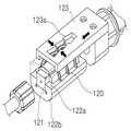
도 4는 본 발명의 다른 실시예에 따른 고정 구조(100)에 관한 사시도이다. 그리고, 도 5는 도 4에 도시된 고정 구조(100)의 구성요소 중 C형 링(120)을 나타내는 도면이다. 본 실시예에 따르면, 스프링(110) 대신에 C형 링(120)을 채용하여 이것이 와이어 고정 보조 부재(121)를 감싸는 부분의 내부 공간이 줄어들게끔 함으로써, 와이어를 고정시킬 수 있게 된다.
본 실시예의 C형 링(120)(바람직하게는, 다수의 C형 링(120))은 와이어 고정 보조 부재(121)를 감싸고 있을 수 있다. 이러한 C형 링(120)은 그 양단에 돌출부(120a)를 포함할 수 있는데, 이와 같은 돌출부(120a)는 직선 운동 부재(123)에 형성된 홈(123a) 내에 배치될 수 있다. 이러한 홈(123a)은, 도시된 바와 같이, 직선 운동 부재(123)가 작용하면(예를 들어, 직선 운동 부재(123)가 샤프트(200) 쪽으로 직선 운동을 하면) 돌출부(120a) 사이의 간격이 좁아져서 C형 링(120)이 와이어 고정 보조 부재(121)를 조이게끔 하는 형태(바람직하게는, 쐐기형이나 그와 유사한 형태)로 형성되어 있을 수 있다. 따라서, 본 실시예에 따르는 경우에도, 상기 실시예에 따르는 경우와 마찬가지로, 와이어를 고정시킬 수 있게 된다. 한편, C형 링(120)과 와이어 고정 보조 부재(121) 중 돌출부(120a)를 제외한 부분은 커버(122a, 122b)에 의하여 커버링될 수 있고, 와이어 고정 보조 부재(121)의 단부(도 4에서 직육면체와 유사한 형태로 표현된 부분)는 와이어 고정 보조 부재(121)가 커버(122a, 122b)에 대하여 어느 정도 고정되도록 하는 것일 수 있다.
도 6은 본 발명의 또 다른 실시예에 따른 고정 구조(100)에 관한 사시도이다. 본 실시예에 따르면, 스프링(130)을 채용하되 직선 운동 부재(132)가 이것의 양단에 대하여 작용하도록 하여 스프링(130)이 와이어 고정 보조 부재(131)의 외측면을 감싸는 부분의 내부 공간이 줄어들게끔 함으로써, 와이어를 고정시킬 수 있게 된다.
본 실시예의 스프링(130)은 와이어 고정 보조 부재(131)의 외측면을 감싸고 있을 수 있다. 이러한 스프링(130)의 양단에는 돌출부(130a)가 형성되어 있을 수 있다. 한편, 직선 운동 부재(132)는, 그것이 샤프트(200) 쪽으로 직선 운동을 하는 경우에, 스프링(130)의 돌출부(130a)에 대하여 작용하여 스프링(130)이 와이어 고정 보조 부재(131)를 조이게끔 할 수 있는 전방 홈(133)과 후방 홈(134)을 포함할 수 있다(돌출부(130a)는 위와 같은 전방 홈(133)과 후방 홈(134)에 삽입되어 있을 수 있다). 이러한 전방 홈(133)과 후방 홈(134)은, 도시된 바와 같이, 직선 운동 부재(132)가 샤프트(200) 쪽으로 직선 운동을 하는 방향에 대하여 경사진 방향으로 그리고 서로 반대되는 경사를 갖도록 형성되어 있을 수 있다. 따라서, 본 실시예에 따르는 경우에도, 상기 실시예에 따르는 경우와 마찬가지로, 와이어를 고정시킬 수 있게 된다.
도 7은 본 발명의 또 다른 실시예에 따른 고정 구조(100)에 관한 사시도이다. 그리고, 도 8은 도 7에 도시된 고정 구조(100)의 구성요소 중 와이어 고정 보조 부재(141)에 관한 사시도이다. 본 실시예에 따르면, 스프링(140)을 채용하되, 직선 운동 부재(142)의 작용에 따라 스프링(140)이 그 양단에 연결되는 두 개의 회전 운동 부재(143, 144)에 의하여 뒤틀리도록 하여, 스프링(140)이 와이어 고정 보조 부재(141)의 외측면을 감싸는 부분의 내부 공간이 줄어들게끔 함으로써, 와이어를 고정시킬 수 있게 된다.
본 실시예의 스프링(140)은 와이어 고정 보조 부재(141)의 외측면을 감싸고 있을 수 있다. 이러한 스프링(140)의 양단은 각각 제1 회전 운동 부재(143)나 제2 회전 운동 부재(144)에 연결되어 있을 수 있다. 그러므로, 제1 회전 운동 부재(143)와 제2 회전 운동 부재(144)가 서로 반대되는 방향으로 회전하면, 이에 따라 스프링(140)이 뒤틀리게 될 수 있다. 한편, 제1 회전 운동 부재(143)와 제2 회전 운동 부재(144)는 각각 돌출부(143a)나 돌출부(144a)를 포함할 수 있다.
또한, 직선 운동 부재(142)가 더 포함되어 있을 수 있다. 이러한 직선 운동 부재(142)는 제1 경사면(142a)과 제2 경사면(142b)을 포함할 수 있다. 제1 경사면(142a)과 제2 경사면(142b)은 각각 제1 회전 운동 부재(143)나 제2 회전 운동 부재(144)의 위와 같은 회전 운동이 가능하도록 하는 방향으로 경사진 면일 수 있다(물론, 이에 대응하여, 돌출부(143a)와 돌출부(144a)도 경사면을 포함할 수 있다).
따라서, 예를 들면, 직선 운동 부재(142)가 샤프트(200) 쪽으로 직선 운동을 하는 경우, 제1 경사면(142a)이 돌출부(143a)에 대하여 힘을 가하여 제1 회전 운동 부재(143)가 시계 방향(핸들부(300) 쪽에서 본 경우)으로 회전할 수 있고, 제2 경사면(142b)이 돌출부(144a)에 대하여 힘을 가하여 제2 회전 운동 부재(144)가 반시계 방향으로 회전할 수 있다. 그러므로, 본 실시예에 따르는 경우에도, 상기 실시예에 따르는 경우와 마찬가지로, 와이어를 고정시킬 수 있게 된다. 한편, 도 8에 도시된 바와 같이, 와이어 고정 보조 부재(141)는 스프링 고정부(141a)를 포함할 수 있는데, 이는 스프링(140)이 불필요하게 샤프트(200) 쪽 방향이나 그 반대 방향 등으로 움직이는 것을 방지하기 위한 것일 수 있다. 이러한 스프링 고정부(141a)와 같은 구성요소는 스프링을 채용하는 위의 다른 실시예에서도 이용될 수 있다.1 is a view showing an overall structure of a minimally invasive surgical instrument according to an embodiment of the present invention.
It looks at with reference to FIG. The minimally invasive surgical instrument may include a fixed structure 100 (ie, a joint fixed structure), a
First, the
Next, the
Next, the first
Next, the
Finally, the fixing
FIG. 2 is a partial cross-sectional view of the minimally invasive surgical instrument shown in FIG. 1. Hereinafter, the fixing
The fixing
One end of the
3 is a partial cross-sectional view of the fixing
The
When the
4 is a perspective view of a fixing
C-shaped ring 120 (preferably, a plurality of C-shaped ring 120) of the present embodiment may surround the wire fixing
6 is a perspective view of a fixing
The
7 is a perspective view of a fixing
In addition, the
Thus, for example, when the
삭제delete
삭제delete
삭제delete
삭제delete
삭제delete
삭제delete
삭제delete
삭제delete
삭제delete
삭제delete
삭제delete
삭제delete
삭제delete
삭제delete
삭제delete
삭제delete
삭제delete
삭제delete
삭제delete
삭제delete
본 발명의The활용예Examples
본 발명의 활용예에 따르면, 당업자는 필요에 따라 최소 침습 수술 기구의 와이어나 토크 전달 부재가 수술용 로봇 등과 같은 다른 모터 기반 시스템(미도시됨)의 전기 모터 등에 의하여 동작하거나 고정될 수 있도록 하기 위하여, 핸들부 등의 형태 등을 일부 변경할 수 있다.
이상에서 본 발명이 구체적인 구성요소 등과 같은 특정 사항과 한정된 실시예 및 도면에 의하여 설명되었으나, 이는 본 발명의 보다 전반적인 이해를 돕기 위하여 제공된 것일 뿐, 본 발명이 상기 실시예에 한정되는 것은 아니며, 본 발명이 속하는 기술분야에서 통상적인 지식을 가진 자라면 이러한 기재로부터 다양한 수정 및 변경을 꾀할 수 있다.
따라서, 본 발명의 사상은 상기 설명된 실시예에 국한되어 정해져서는 아니 되며, 후술하는 특허청구범위뿐만 아니라 이 특허청구범위와 균등한 또는 이로부터 등가적으로 변경된 모든 범위는 본 발명의 사상의 범주에 속한다고 할 것이다.According to the application of the present invention, those skilled in the art can make the wire or torque transmitting member of the minimally invasive surgical instrument operate or be fixed by an electric motor or the like of another motor-based system (not shown), such as a surgical robot, if necessary. In order to change the shape of the handle portion or the like, it is possible to partially change it.
Although the present invention has been described by specific matters such as specific components and limited embodiments and drawings, it is provided only to help a more general understanding of the present invention, and the present invention is not limited to the above embodiments. Those skilled in the art can make various modifications and changes from this description.
Therefore, the spirit of the present invention should not be limited to the above-described embodiments, and the scope of the spirit of the present invention is defined not only in the claims below, but also in the ranges equivalent to or equivalent to the claims. Will belong to.
삭제delete
삭제delete
100: 고정 구조
200: 샤프트
300: 핸들부
400: 제1 관절부
500: 제2 관절부
600: 엔드 이펙터100: fixed structure
200: Shaft
300: handle portion
400: first joint portion
500: second joint portion
600: end effector
Claims (10)
Translated fromKorean샤프트,
상기 샤프트의 일단 쪽에 연결되는 엔드 이펙터,
상기 엔드 이펙터의 관절 운동을 제어하기 위한 와이어, 및
상기 엔드 이펙터의 관절 운동 상태가 고정되도록 하기 위한 고정 구조
를 포함하고,
상기 고정 구조는 상기 와이어를 감싸는 탄성 부재를 포함하며,
상기 탄성 부재는 그 내부 공간이 줄어듦에 따라 상기 와이어를 붙잡아 주고,
상기 고정 구조는 상기 와이어를 유도하거나 지지하는 와이어 고정 보조 부재를 더 포함하며,
상기 탄성 부재는 상기 와이어 고정 보조 부재를 더 감싸는
최소 침습 수술 기구.As a minimally invasive surgical instrument,
shaft,
An end effector connected to one end of the shaft,
A wire for controlling joint motion of the end effector, and
Fixing structure for fixing the joint motion state of the end effector
Lt; / RTI >
The fixing structure includes an elastic member surrounding the wire,
The elastic member grips the wire as its inner space is reduced,
The fixing structure further includes a wire fixing auxiliary member for guiding or supporting the wire,
The elastic member further wraps the wire fixing auxiliary member
Minimally invasive surgical instrument.
상기 와이어 고정 보조 부재는 와이어 유도 경로를 포함하는 최소 침습 수술 기구.3. The method of claim 2,
And the wire fixation assist member comprises a wire guidance path.
상기 고정 구조는 회전 운동 부재를 더 포함하고,
상기 탄성 부재는 그 일단이 상기 회전 운동 부재에 연결되어 있는 스프링이며,
상기 회전 운동 부재가 회전함에 따라 상기 탄성 부재의 상기 내부 공간이 줄어들게 되는
최소 침습 수술 기구.3. The method of claim 2,
The fixed structure further includes a rotational movement member,
The elastic member is a spring whose one end is connected to the rotary motion member,
The inner space of the elastic member is reduced as the rotary motion member rotates
Minimally invasive surgical instrument.
상기 고정 구조는 두 개의 회전 운동 부재를 더 포함하고,
상기 탄성 부재는 그 양단이 상기 두 개의 회전 운동 부재에 각각 연결되어 있는 스프링이며,
상기 두 개의 회전 운동 부재가 서로 반대 방향으로 회전함에 따라 상기 탄성 부재의 상기 내부 공간이 줄어들게 되는
최소 침습 수술 기구.3. The method of claim 2,
The fixed structure further includes two rotational movement members,
The elastic member is a spring whose both ends are respectively connected to the two rotary motion member,
As the two rotary motion members rotate in opposite directions, the inner space of the elastic member is reduced.
Minimally invasive surgical instrument.
상기 고정 구조는 직선 운동 부재를 더 포함하고,
상기 직선 운동 부재의 직선 운동에 따라 상기 탄성 부재의 상기 내부 공간이 줄어들게 되는
최소 침습 수술 기구.The method according to claim 4 or 5,
The fixed structure further includes a linear motion member,
The inner space of the elastic member is reduced according to the linear movement of the linear motion member.
Minimally invasive surgical instrument.
상기 탄성 부재는 C형 링이고,
상기 고정 구조는 쐐기형 홈을 포함하는 직선 운동 부재를 더 포함하며,
상기 탄성 부재의 돌출부가 상기 쐐기형 홈 내에 배치되는
최소 침습 수술 기구.3. The method of claim 2,
The elastic member is a C-type ring,
The fixed structure further includes a linear motion member including a wedge-shaped groove,
The protrusion of the elastic member is disposed in the wedge-shaped groove
Minimally invasive surgical instrument.
상기 탄성 부재는 스프링이고,
상기 고정 구조는 전방 홈과 후방 홈을 포함하는 직선 운동 부재를 더 포함하며,
상기 탄성 부재의 양단의 돌출부가 상기 전방 홈과 상기 후방 홈에 각각 삽입되어 있는
최소 침습 수술 기구.3. The method of claim 2,
The elastic member is a spring,
The fixing structure further includes a linear motion member including a front groove and a rear groove,
Protrusions at both ends of the elastic member are inserted into the front groove and the rear groove, respectively.
Minimally invasive surgical instrument.
상기 전방 홈과 상기 후방 홈은 상기 직선 운동 부재의 직선 운동 방향에 대하여 경사진 방향으로 형성되고,
상기 전방 홈의 경사 방향과 상기 후방 홈의 경사 방향은 서로 반대인
최소 침습 수술 기구.9. The method of claim 8,
The front groove and the rear groove are formed in a direction inclined with respect to the linear movement direction of the linear motion member,
The inclination direction of the front groove and the inclination direction of the rear groove are opposite to each other.
Minimally invasive surgical instrument.
상기 와이어 고정 보조 부재는 상기 탄성 부재의 움직임을 제한하기 위한 고정부를 포함하는 최소 침습 수술 기구.
The method according to any one of claims 4, 5 and 8,
And the wire fixation assist member includes a fixation for limiting movement of the elastic member.
Priority Applications (7)
| Application Number | Priority Date | Filing Date | Title |
|---|---|---|---|
| KR1020120034090AKR101365357B1 (en) | 2012-04-02 | 2012-04-02 | Instrument for Minimally Invasive Surgery Having Articulation Fixing Structure |
| PCT/KR2013/002472WO2013151262A1 (en) | 2012-04-02 | 2013-03-26 | Minimally invasive surgical instrument having articulation immobilising structure |
| EP13772986.9AEP2835107B1 (en) | 2012-04-02 | 2013-03-26 | Minimally invasive surgical instrument having articulation immobilising structure |
| US14/390,287US10194891B2 (en) | 2012-04-02 | 2013-03-26 | Minimally invasive surgical instrument having articulation immobilising structure |
| CN201380005392.4ACN104093372A (en) | 2012-04-02 | 2013-03-26 | Minimally invasive surgical instrument having articulation immobilising structure |
| JP2015503115AJP2015513951A (en) | 2012-04-02 | 2013-03-26 | Minimally invasive surgical instrument with joint fixation structure |
| US16/231,661US10966695B2 (en) | 2012-04-02 | 2018-12-24 | Minimally invasive surgical instrument having articulation immobilising structure |
Applications Claiming Priority (1)
| Application Number | Priority Date | Filing Date | Title |
|---|---|---|---|
| KR1020120034090AKR101365357B1 (en) | 2012-04-02 | 2012-04-02 | Instrument for Minimally Invasive Surgery Having Articulation Fixing Structure |
Publications (2)
| Publication Number | Publication Date |
|---|---|
| KR20130111865A KR20130111865A (en) | 2013-10-11 |
| KR101365357B1true KR101365357B1 (en) | 2014-02-20 |
Family
ID=49300709
Family Applications (1)
| Application Number | Title | Priority Date | Filing Date |
|---|---|---|---|
| KR1020120034090AActiveKR101365357B1 (en) | 2012-04-02 | 2012-04-02 | Instrument for Minimally Invasive Surgery Having Articulation Fixing Structure |
Country Status (6)
| Country | Link |
|---|---|
| US (2) | US10194891B2 (en) |
| EP (1) | EP2835107B1 (en) |
| JP (1) | JP2015513951A (en) |
| KR (1) | KR101365357B1 (en) |
| CN (1) | CN104093372A (en) |
| WO (1) | WO2013151262A1 (en) |
Cited By (1)
| Publication number | Priority date | Publication date | Assignee | Title |
|---|---|---|---|---|
| WO2023080630A1 (en)* | 2021-11-03 | 2023-05-11 | 이화여자대학교 산학협력단 | Wire-based steering needle driving device |
Families Citing this family (114)
| Publication number | Priority date | Publication date | Assignee | Title |
|---|---|---|---|---|
| US11871901B2 (en) | 2012-05-20 | 2024-01-16 | Cilag Gmbh International | Method for situational awareness for surgical network or surgical network connected device capable of adjusting function based on a sensed situation or usage |
| DE102013005982A1 (en)* | 2013-04-08 | 2014-10-09 | Kuka Laboratories Gmbh | medical robots |
| US11504192B2 (en) | 2014-10-30 | 2022-11-22 | Cilag Gmbh International | Method of hub communication with surgical instrument systems |
| US11510741B2 (en) | 2017-10-30 | 2022-11-29 | Cilag Gmbh International | Method for producing a surgical instrument comprising a smart electrical system |
| US11026687B2 (en) | 2017-10-30 | 2021-06-08 | Cilag Gmbh International | Clip applier comprising clip advancing systems |
| US11564756B2 (en) | 2017-10-30 | 2023-01-31 | Cilag Gmbh International | Method of hub communication with surgical instrument systems |
| US11229436B2 (en) | 2017-10-30 | 2022-01-25 | Cilag Gmbh International | Surgical system comprising a surgical tool and a surgical hub |
| US11801098B2 (en) | 2017-10-30 | 2023-10-31 | Cilag Gmbh International | Method of hub communication with surgical instrument systems |
| US11317919B2 (en) | 2017-10-30 | 2022-05-03 | Cilag Gmbh International | Clip applier comprising a clip crimping system |
| US11291510B2 (en) | 2017-10-30 | 2022-04-05 | Cilag Gmbh International | Method of hub communication with surgical instrument systems |
| US11925373B2 (en) | 2017-10-30 | 2024-03-12 | Cilag Gmbh International | Surgical suturing instrument comprising a non-circular needle |
| US11311342B2 (en) | 2017-10-30 | 2022-04-26 | Cilag Gmbh International | Method for communicating with surgical instrument systems |
| US11911045B2 (en) | 2017-10-30 | 2024-02-27 | Cllag GmbH International | Method for operating a powered articulating multi-clip applier |
| US11896322B2 (en) | 2017-12-28 | 2024-02-13 | Cilag Gmbh International | Sensing the patient position and contact utilizing the mono-polar return pad electrode to provide situational awareness to the hub |
| US11026751B2 (en) | 2017-12-28 | 2021-06-08 | Cilag Gmbh International | Display of alignment of staple cartridge to prior linear staple line |
| US11304763B2 (en) | 2017-12-28 | 2022-04-19 | Cilag Gmbh International | Image capturing of the areas outside the abdomen to improve placement and control of a surgical device in use |
| US11633237B2 (en) | 2017-12-28 | 2023-04-25 | Cilag Gmbh International | Usage and technique analysis of surgeon / staff performance against a baseline to optimize device utilization and performance for both current and future procedures |
| US10918310B2 (en) | 2018-01-03 | 2021-02-16 | Biosense Webster (Israel) Ltd. | Fast anatomical mapping (FAM) using volume filling |
| US20190201112A1 (en) | 2017-12-28 | 2019-07-04 | Ethicon Llc | Computer implemented interactive surgical systems |
| US11744604B2 (en) | 2017-12-28 | 2023-09-05 | Cilag Gmbh International | Surgical instrument with a hardware-only control circuit |
| US11389164B2 (en) | 2017-12-28 | 2022-07-19 | Cilag Gmbh International | Method of using reinforced flexible circuits with multiple sensors to optimize performance of radio frequency devices |
| US11559308B2 (en) | 2017-12-28 | 2023-01-24 | Cilag Gmbh International | Method for smart energy device infrastructure |
| US11937769B2 (en) | 2017-12-28 | 2024-03-26 | Cilag Gmbh International | Method of hub communication, processing, storage and display |
| US11786245B2 (en) | 2017-12-28 | 2023-10-17 | Cilag Gmbh International | Surgical systems with prioritized data transmission capabilities |
| US11013563B2 (en) | 2017-12-28 | 2021-05-25 | Ethicon Llc | Drive arrangements for robot-assisted surgical platforms |
| US11308075B2 (en) | 2017-12-28 | 2022-04-19 | Cilag Gmbh International | Surgical network, instrument, and cloud responses based on validation of received dataset and authentication of its source and integrity |
| US11273001B2 (en) | 2017-12-28 | 2022-03-15 | Cilag Gmbh International | Surgical hub and modular device response adjustment based on situational awareness |
| US20190201142A1 (en) | 2017-12-28 | 2019-07-04 | Ethicon Llc | Automatic tool adjustments for robot-assisted surgical platforms |
| US11284936B2 (en) | 2017-12-28 | 2022-03-29 | Cilag Gmbh International | Surgical instrument having a flexible electrode |
| US11179175B2 (en) | 2017-12-28 | 2021-11-23 | Cilag Gmbh International | Controlling an ultrasonic surgical instrument according to tissue location |
| US11696760B2 (en) | 2017-12-28 | 2023-07-11 | Cilag Gmbh International | Safety systems for smart powered surgical stapling |
| US11464535B2 (en) | 2017-12-28 | 2022-10-11 | Cilag Gmbh International | Detection of end effector emersion in liquid |
| US11234756B2 (en) | 2017-12-28 | 2022-02-01 | Cilag Gmbh International | Powered surgical tool with predefined adjustable control algorithm for controlling end effector parameter |
| US11364075B2 (en) | 2017-12-28 | 2022-06-21 | Cilag Gmbh International | Radio frequency energy device for delivering combined electrical signals |
| US11202570B2 (en) | 2017-12-28 | 2021-12-21 | Cilag Gmbh International | Communication hub and storage device for storing parameters and status of a surgical device to be shared with cloud based analytics systems |
| US11076921B2 (en) | 2017-12-28 | 2021-08-03 | Cilag Gmbh International | Adaptive control program updates for surgical hubs |
| US11659023B2 (en) | 2017-12-28 | 2023-05-23 | Cilag Gmbh International | Method of hub communication |
| US11424027B2 (en) | 2017-12-28 | 2022-08-23 | Cilag Gmbh International | Method for operating surgical instrument systems |
| US11571234B2 (en) | 2017-12-28 | 2023-02-07 | Cilag Gmbh International | Temperature control of ultrasonic end effector and control system therefor |
| US11291495B2 (en) | 2017-12-28 | 2022-04-05 | Cilag Gmbh International | Interruption of energy due to inadvertent capacitive coupling |
| US11786251B2 (en) | 2017-12-28 | 2023-10-17 | Cilag Gmbh International | Method for adaptive control schemes for surgical network control and interaction |
| US10892995B2 (en) | 2017-12-28 | 2021-01-12 | Ethicon Llc | Surgical network determination of prioritization of communication, interaction, or processing based on system or device needs |
| US11464559B2 (en) | 2017-12-28 | 2022-10-11 | Cilag Gmbh International | Estimating state of ultrasonic end effector and control system therefor |
| US20190206569A1 (en) | 2017-12-28 | 2019-07-04 | Ethicon Llc | Method of cloud based data analytics for use with the hub |
| US11903601B2 (en) | 2017-12-28 | 2024-02-20 | Cilag Gmbh International | Surgical instrument comprising a plurality of drive systems |
| US11529187B2 (en) | 2017-12-28 | 2022-12-20 | Cilag Gmbh International | Surgical evacuation sensor arrangements |
| US11602393B2 (en) | 2017-12-28 | 2023-03-14 | Cilag Gmbh International | Surgical evacuation sensing and generator control |
| US11304745B2 (en) | 2017-12-28 | 2022-04-19 | Cilag Gmbh International | Surgical evacuation sensing and display |
| US11832899B2 (en) | 2017-12-28 | 2023-12-05 | Cilag Gmbh International | Surgical systems with autonomously adjustable control programs |
| US11304699B2 (en) | 2017-12-28 | 2022-04-19 | Cilag Gmbh International | Method for adaptive control schemes for surgical network control and interaction |
| US11540855B2 (en) | 2017-12-28 | 2023-01-03 | Cilag Gmbh International | Controlling activation of an ultrasonic surgical instrument according to the presence of tissue |
| US12096916B2 (en) | 2017-12-28 | 2024-09-24 | Cilag Gmbh International | Method of sensing particulate from smoke evacuated from a patient, adjusting the pump speed based on the sensed information, and communicating the functional parameters of the system to the hub |
| US11324557B2 (en) | 2017-12-28 | 2022-05-10 | Cilag Gmbh International | Surgical instrument with a sensing array |
| US11832840B2 (en) | 2017-12-28 | 2023-12-05 | Cilag Gmbh International | Surgical instrument having a flexible circuit |
| US11666331B2 (en) | 2017-12-28 | 2023-06-06 | Cilag Gmbh International | Systems for detecting proximity of surgical end effector to cancerous tissue |
| WO2019133144A1 (en) | 2017-12-28 | 2019-07-04 | Ethicon Llc | Detection and escalation of security responses of surgical instruments to increasing severity threats |
| US12376855B2 (en) | 2017-12-28 | 2025-08-05 | Cilag Gmbh International | Safety systems for smart powered surgical stapling |
| US12127729B2 (en) | 2017-12-28 | 2024-10-29 | Cilag Gmbh International | Method for smoke evacuation for surgical hub |
| US11969216B2 (en) | 2017-12-28 | 2024-04-30 | Cilag Gmbh International | Surgical network recommendations from real time analysis of procedure variables against a baseline highlighting differences from the optimal solution |
| US11132462B2 (en) | 2017-12-28 | 2021-09-28 | Cilag Gmbh International | Data stripping method to interrogate patient records and create anonymized record |
| US12062442B2 (en) | 2017-12-28 | 2024-08-13 | Cilag Gmbh International | Method for operating surgical instrument systems |
| US11419630B2 (en) | 2017-12-28 | 2022-08-23 | Cilag Gmbh International | Surgical system distributed processing |
| US11266468B2 (en) | 2017-12-28 | 2022-03-08 | Cilag Gmbh International | Cooperative utilization of data derived from secondary sources by intelligent surgical hubs |
| US12396806B2 (en) | 2017-12-28 | 2025-08-26 | Cilag Gmbh International | Adjustment of a surgical device function based on situational awareness |
| US11376002B2 (en) | 2017-12-28 | 2022-07-05 | Cilag Gmbh International | Surgical instrument cartridge sensor assemblies |
| US20190201090A1 (en) | 2017-12-28 | 2019-07-04 | Ethicon Llc | Capacitive coupled return path pad with separable array elements |
| US11160605B2 (en) | 2017-12-28 | 2021-11-02 | Cilag Gmbh International | Surgical evacuation sensing and motor control |
| US11166772B2 (en) | 2017-12-28 | 2021-11-09 | Cilag Gmbh International | Surgical hub coordination of control and communication of operating room devices |
| US11998193B2 (en) | 2017-12-28 | 2024-06-04 | Cilag Gmbh International | Method for usage of the shroud as an aspect of sensing or controlling a powered surgical device, and a control algorithm to adjust its default operation |
| US11818052B2 (en) | 2017-12-28 | 2023-11-14 | Cilag Gmbh International | Surgical network determination of prioritization of communication, interaction, or processing based on system or device needs |
| US11559307B2 (en) | 2017-12-28 | 2023-01-24 | Cilag Gmbh International | Method of robotic hub communication, detection, and control |
| US20190201039A1 (en) | 2017-12-28 | 2019-07-04 | Ethicon Llc | Situational awareness of electrosurgical systems |
| US11576677B2 (en) | 2017-12-28 | 2023-02-14 | Cilag Gmbh International | Method of hub communication, processing, display, and cloud analytics |
| US11096693B2 (en) | 2017-12-28 | 2021-08-24 | Cilag Gmbh International | Adjustment of staple height of at least one row of staples based on the sensed tissue thickness or force in closing |
| US11896443B2 (en) | 2017-12-28 | 2024-02-13 | Cilag Gmbh International | Control of a surgical system through a surgical barrier |
| US11423007B2 (en) | 2017-12-28 | 2022-08-23 | Cilag Gmbh International | Adjustment of device control programs based on stratified contextual data in addition to the data |
| US11589888B2 (en) | 2017-12-28 | 2023-02-28 | Cilag Gmbh International | Method for controlling smart energy devices |
| US11317937B2 (en) | 2018-03-08 | 2022-05-03 | Cilag Gmbh International | Determining the state of an ultrasonic end effector |
| US11678881B2 (en) | 2017-12-28 | 2023-06-20 | Cilag Gmbh International | Spatial awareness of surgical hubs in operating rooms |
| US11253315B2 (en) | 2017-12-28 | 2022-02-22 | Cilag Gmbh International | Increasing radio frequency to create pad-less monopolar loop |
| US11278281B2 (en) | 2017-12-28 | 2022-03-22 | Cilag Gmbh International | Interactive surgical system |
| US11612444B2 (en) | 2017-12-28 | 2023-03-28 | Cilag Gmbh International | Adjustment of a surgical device function based on situational awareness |
| US11857152B2 (en) | 2017-12-28 | 2024-01-02 | Cilag Gmbh International | Surgical hub spatial awareness to determine devices in operating theater |
| US11446052B2 (en) | 2017-12-28 | 2022-09-20 | Cilag Gmbh International | Variation of radio frequency and ultrasonic power level in cooperation with varying clamp arm pressure to achieve predefined heat flux or power applied to tissue |
| US11257589B2 (en) | 2017-12-28 | 2022-02-22 | Cilag Gmbh International | Real-time analysis of comprehensive cost of all instrumentation used in surgery utilizing data fluidity to track instruments through stocking and in-house processes |
| US11304720B2 (en) | 2017-12-28 | 2022-04-19 | Cilag Gmbh International | Activation of energy devices |
| US11109866B2 (en) | 2017-12-28 | 2021-09-07 | Cilag Gmbh International | Method for circular stapler control algorithm adjustment based on situational awareness |
| US11969142B2 (en) | 2017-12-28 | 2024-04-30 | Cilag Gmbh International | Method of compressing tissue within a stapling device and simultaneously displaying the location of the tissue within the jaws |
| US11432885B2 (en) | 2017-12-28 | 2022-09-06 | Cilag Gmbh International | Sensing arrangements for robot-assisted surgical platforms |
| US11311306B2 (en) | 2017-12-28 | 2022-04-26 | Cilag Gmbh International | Surgical systems for detecting end effector tissue distribution irregularities |
| US11419667B2 (en) | 2017-12-28 | 2022-08-23 | Cilag Gmbh International | Ultrasonic energy device which varies pressure applied by clamp arm to provide threshold control pressure at a cut progression location |
| US11410259B2 (en) | 2017-12-28 | 2022-08-09 | Cilag Gmbh International | Adaptive control program updates for surgical devices |
| US10758310B2 (en) | 2017-12-28 | 2020-09-01 | Ethicon Llc | Wireless pairing of a surgical device with another device within a sterile surgical field based on the usage and situational awareness of devices |
| US11864728B2 (en) | 2017-12-28 | 2024-01-09 | Cilag Gmbh International | Characterization of tissue irregularities through the use of mono-chromatic light refractivity |
| US11179208B2 (en) | 2017-12-28 | 2021-11-23 | Cilag Gmbh International | Cloud-based medical analytics for security and authentication trends and reactive measures |
| US11534196B2 (en) | 2018-03-08 | 2022-12-27 | Cilag Gmbh International | Using spectroscopy to determine device use state in combo instrument |
| US11259830B2 (en) | 2018-03-08 | 2022-03-01 | Cilag Gmbh International | Methods for controlling temperature in ultrasonic device |
| US12303159B2 (en) | 2018-03-08 | 2025-05-20 | Cilag Gmbh International | Methods for estimating and controlling state of ultrasonic end effector |
| US11986233B2 (en) | 2018-03-08 | 2024-05-21 | Cilag Gmbh International | Adjustment of complex impedance to compensate for lost power in an articulating ultrasonic device |
| US11090047B2 (en) | 2018-03-28 | 2021-08-17 | Cilag Gmbh International | Surgical instrument comprising an adaptive control system |
| US11213294B2 (en) | 2018-03-28 | 2022-01-04 | Cilag Gmbh International | Surgical instrument comprising co-operating lockout features |
| US11471156B2 (en) | 2018-03-28 | 2022-10-18 | Cilag Gmbh International | Surgical stapling devices with improved rotary driven closure systems |
| US11589865B2 (en) | 2018-03-28 | 2023-02-28 | Cilag Gmbh International | Methods for controlling a powered surgical stapler that has separate rotary closure and firing systems |
| US11207067B2 (en) | 2018-03-28 | 2021-12-28 | Cilag Gmbh International | Surgical stapling device with separate rotary driven closure and firing systems and firing member that engages both jaws while firing |
| US11219453B2 (en) | 2018-03-28 | 2022-01-11 | Cilag Gmbh International | Surgical stapling devices with cartridge compatible closure and firing lockout arrangements |
| US11278280B2 (en) | 2018-03-28 | 2022-03-22 | Cilag Gmbh International | Surgical instrument comprising a jaw closure lockout |
| US11357503B2 (en) | 2019-02-19 | 2022-06-14 | Cilag Gmbh International | Staple cartridge retainers with frangible retention features and methods of using same |
| US11369377B2 (en) | 2019-02-19 | 2022-06-28 | Cilag Gmbh International | Surgical stapling assembly with cartridge based retainer configured to unlock a firing lockout |
| US11317915B2 (en) | 2019-02-19 | 2022-05-03 | Cilag Gmbh International | Universal cartridge based key feature that unlocks multiple lockout arrangements in different surgical staplers |
| US11464511B2 (en) | 2019-02-19 | 2022-10-11 | Cilag Gmbh International | Surgical staple cartridges with movable authentication key arrangements |
| US11331100B2 (en) | 2019-02-19 | 2022-05-17 | Cilag Gmbh International | Staple cartridge retainer system with authentication keys |
| USD964564S1 (en) | 2019-06-25 | 2022-09-20 | Cilag Gmbh International | Surgical staple cartridge retainer with a closure system authentication key |
| USD950728S1 (en) | 2019-06-25 | 2022-05-03 | Cilag Gmbh International | Surgical staple cartridge |
| USD952144S1 (en) | 2019-06-25 | 2022-05-17 | Cilag Gmbh International | Surgical staple cartridge retainer with firing system authentication key |
Citations (4)
| Publication number | Priority date | Publication date | Assignee | Title |
|---|---|---|---|---|
| JP2008049104A (en)* | 2006-08-28 | 2008-03-06 | River Seiko:Kk | Endoscopic treatment tool |
| JP2010136831A (en) | 2008-12-10 | 2010-06-24 | Fujifilm Corp | Repeating type clip treatment instrument |
| JP2010207340A (en) | 2009-03-09 | 2010-09-24 | Hoya Corp | Endoscope guiding tube device |
| KR101075294B1 (en) | 2011-01-12 | 2011-10-19 | 정창욱 | Minimally invasive surgical instruments |
Family Cites Families (20)
| Publication number | Priority date | Publication date | Assignee | Title |
|---|---|---|---|---|
| US5374277A (en)* | 1992-10-09 | 1994-12-20 | Ethicon, Inc. | Surgical instrument |
| US20050182298A1 (en)* | 2002-12-06 | 2005-08-18 | Intuitive Surgical Inc. | Cardiac tissue ablation instrument with flexible wrist |
| US8764765B2 (en)* | 2003-09-23 | 2014-07-01 | Covidien Lp | Laparoscopic instrument and related surgical method |
| US7147650B2 (en)* | 2003-10-30 | 2006-12-12 | Woojin Lee | Surgical instrument |
| US7686826B2 (en)* | 2003-10-30 | 2010-03-30 | Cambridge Endoscopic Devices, Inc. | Surgical instrument |
| KR101163254B1 (en) | 2004-04-14 | 2012-07-09 | 타이코 일렉트로닉스 코포레이션 | Acoustic touch sensor |
| US7828808B2 (en)* | 2004-06-07 | 2010-11-09 | Novare Surgical Systems, Inc. | Link systems and articulation mechanisms for remote manipulation of surgical or diagnostic tools |
| CN101048101B (en)* | 2004-06-07 | 2012-11-14 | 诺瓦尔外科系统公司 | Articulation mechanism with flexibly articulated links |
| DE602006016652D1 (en) | 2006-03-01 | 2010-10-14 | Nokia Corp | Control of a receiver to reduce the influence of a fault |
| KR20080051248A (en) | 2006-12-05 | 2008-06-11 | 채수하 | Fireproof Sandwich Panel |
| KR20080061894A (en) | 2006-12-28 | 2008-07-03 | 엘지전자 주식회사 | Liquid crystal display panel and its manufacturing method |
| KR20080079126A (en) | 2007-02-26 | 2008-08-29 | 주식회사 유니베라 | Whitening cosmetic composition comprising aloe vera and licorice extract |
| US7922063B2 (en)* | 2007-10-31 | 2011-04-12 | Tyco Healthcare Group, Lp | Powered surgical instrument |
| US10408576B2 (en) | 2008-10-27 | 2019-09-10 | Plaskolite Massachusetts, Llc | High-energy impact absorbing polycarbonate mounting method |
| KR20100115152A (en) | 2009-04-17 | 2010-10-27 | 김영환 | A work lamp |
| KR20110003192A (en) | 2009-07-03 | 2011-01-11 | 주식회사 루멘스 | Street light system |
| KR20110026243A (en) | 2009-09-07 | 2011-03-15 | 주식회사 인지디스플레이 | Oil injection device for press machining of chassis |
| KR101036718B1 (en) | 2009-09-16 | 2011-05-24 | 김광례 | Cauldron type steam generator |
| US9339631B2 (en)* | 2009-09-25 | 2016-05-17 | Boston Scientific Scimed, Inc. | Locking mechanism for a medical device |
| US8968357B2 (en)* | 2010-09-07 | 2015-03-03 | Covidien Lp | Collet based locking mechanism |
- 2012
- 2012-04-02KRKR1020120034090Apatent/KR101365357B1/enactiveActive
- 2013
- 2013-03-26WOPCT/KR2013/002472patent/WO2013151262A1/enactiveApplication Filing
- 2013-03-26EPEP13772986.9Apatent/EP2835107B1/enactiveActive
- 2013-03-26JPJP2015503115Apatent/JP2015513951A/enactivePending
- 2013-03-26USUS14/390,287patent/US10194891B2/enactiveActive
- 2013-03-26CNCN201380005392.4Apatent/CN104093372A/enactivePending
- 2018
- 2018-12-24USUS16/231,661patent/US10966695B2/enactiveActive
Patent Citations (4)
| Publication number | Priority date | Publication date | Assignee | Title |
|---|---|---|---|---|
| JP2008049104A (en)* | 2006-08-28 | 2008-03-06 | River Seiko:Kk | Endoscopic treatment tool |
| JP2010136831A (en) | 2008-12-10 | 2010-06-24 | Fujifilm Corp | Repeating type clip treatment instrument |
| JP2010207340A (en) | 2009-03-09 | 2010-09-24 | Hoya Corp | Endoscope guiding tube device |
| KR101075294B1 (en) | 2011-01-12 | 2011-10-19 | 정창욱 | Minimally invasive surgical instruments |
Cited By (1)
| Publication number | Priority date | Publication date | Assignee | Title |
|---|---|---|---|---|
| WO2023080630A1 (en)* | 2021-11-03 | 2023-05-11 | 이화여자대학교 산학협력단 | Wire-based steering needle driving device |
Also Published As
| Publication number | Publication date |
|---|---|
| US20190150905A1 (en) | 2019-05-23 |
| CN104093372A (en) | 2014-10-08 |
| WO2013151262A1 (en) | 2013-10-10 |
| US20150066001A1 (en) | 2015-03-05 |
| US10966695B2 (en) | 2021-04-06 |
| KR20130111865A (en) | 2013-10-11 |
| EP2835107A4 (en) | 2015-09-02 |
| EP2835107B1 (en) | 2017-05-10 |
| US10194891B2 (en) | 2019-02-05 |
| JP2015513951A (en) | 2015-05-18 |
| EP2835107A1 (en) | 2015-02-11 |
Similar Documents
| Publication | Publication Date | Title |
|---|---|---|
| KR101365357B1 (en) | Instrument for Minimally Invasive Surgery Having Articulation Fixing Structure | |
| KR101322030B1 (en) | Instrument for Minimally Invasive Surgery Having Articulation Unit Including Spherical Parts | |
| KR101075294B1 (en) | Minimally invasive surgical instruments | |
| KR101322104B1 (en) | Instrument for Minimally Invasive Surgery Having Attachable/Detachable End Effector | |
| KR101259701B1 (en) | Instrument for Minimally Invasive Surgery Having Curved Shaft | |
| KR101064825B1 (en) | Minimally invasive surgical instruments | |
| KR101521289B1 (en) | Instrument for Minimally Invasive Surgery Having Improved Articulation Unit | |
| KR101455510B1 (en) | Instrument for Minimally Invasive Surgery Having Link-type Articulation Unit | |
| KR102097782B1 (en) | Apparatus for laparoscpoic surgery | |
| EP3761897A1 (en) | Low-friction, small profile medical tools having easy-to-assemble components | |
| US20200397522A1 (en) | Low-friction, small profile medical tools having easy-to-assemble components | |
| KR20140113893A (en) | Instrument for Minimally Invasive Surgery Having Link-type Articulation Unit | |
| KR20130023311A (en) | Instrument for minimally invasive surgery having curved shaft | |
| KR20130009121A (en) | Instrument for minimally invasive surgery that can selectively cover its end effector | |
| KR101259690B1 (en) | Instrument for Minimally Invasive Surgery Having Shaft Including Inner Torque Transmission Member | |
| KR101336381B1 (en) | Instrument for Minimally Invasive Surgery | |
| KR101486645B1 (en) | Instrument for Minimally Invasive Surgery Having Variable Bending | |
| KR20130131276A (en) | Instrument for minimally invasive surgery having improved articulation unit | |
| KR101300404B1 (en) | Motorized Instrument for Minimally Invasive Surgery | |
| KR20130076846A (en) | Instrument for minimally invasive surgery that can selectively cover its end effector | |
| KR20130031312A (en) | Motorized instrument for minimally invasive surgery | |
| KR20130133153A (en) | Instrument for minimally invasive surgery having curved shaft | |
| KR20130025923A (en) | Instrument for minimally invasive surgery having shaft including inner torque transmission member |
Legal Events
| Date | Code | Title | Description |
|---|---|---|---|
| A201 | Request for examination | ||
| PA0109 | Patent application | Patent event code:PA01091R01D Comment text:Patent Application Patent event date:20120402 | |
| PA0201 | Request for examination | ||
| E902 | Notification of reason for refusal | ||
| PE0902 | Notice of grounds for rejection | Comment text:Notification of reason for refusal Patent event date:20130603 Patent event code:PE09021S01D | |
| PG1501 | Laying open of application | ||
| E701 | Decision to grant or registration of patent right | ||
| PE0701 | Decision of registration | Patent event code:PE07011S01D Comment text:Decision to Grant Registration Patent event date:20131114 | |
| GRNT | Written decision to grant | ||
| PR0701 | Registration of establishment | Comment text:Registration of Establishment Patent event date:20140213 Patent event code:PR07011E01D | |
| PR1002 | Payment of registration fee | Payment date:20140213 End annual number:3 Start annual number:1 | |
| PG1601 | Publication of registration | ||
| FPAY | Annual fee payment | Payment date:20170124 Year of fee payment:4 | |
| PR1001 | Payment of annual fee | Payment date:20170124 Start annual number:4 End annual number:4 | |
| FPAY | Annual fee payment | Payment date:20180104 Year of fee payment:5 | |
| PR1001 | Payment of annual fee | Payment date:20180104 Start annual number:5 End annual number:5 | |
| FPAY | Annual fee payment | Payment date:20200106 Year of fee payment:7 | |
| PR1001 | Payment of annual fee | Payment date:20200106 Start annual number:7 End annual number:7 | |
| PR1001 | Payment of annual fee | Payment date:20210204 Start annual number:8 End annual number:8 | |
| PR1001 | Payment of annual fee | Payment date:20220126 Start annual number:9 End annual number:9 | |
| PR1001 | Payment of annual fee | Payment date:20230207 Start annual number:10 End annual number:10 |