KR101364517B1 - Arctic ship with derrick - Google Patents
Arctic ship with derrickDownload PDFInfo
- Publication number
- KR101364517B1 KR101364517B1KR1020110029002AKR20110029002AKR101364517B1KR 101364517 B1KR101364517 B1KR 101364517B1KR 1020110029002 AKR1020110029002 AKR 1020110029002AKR 20110029002 AKR20110029002 AKR 20110029002AKR 101364517 B1KR101364517 B1KR 101364517B1
- Authority
- KR
- South Korea
- Prior art keywords
- derrick
- air
- polar
- space
- ship
- Prior art date
- Legal status (The legal status is an assumption and is not a legal conclusion. Google has not performed a legal analysis and makes no representation as to the accuracy of the status listed.)
- Active
Links
- 238000004891communicationMethods0.000claimsabstractdescription26
- 238000000034methodMethods0.000claimsdescription21
- 238000009434installationMethods0.000claimsdescription17
- 238000007599dischargingMethods0.000claimsdescription5
- 238000010438heat treatmentMethods0.000claimsdescription4
- 239000002245particleSubstances0.000claimsdescription4
- PEDCQBHIVMGVHV-UHFFFAOYSA-NGlycerineChemical compoundOCC(O)COPEDCQBHIVMGVHV-UHFFFAOYSA-N0.000description17
- 238000005553drillingMethods0.000description15
- 238000012423maintenanceMethods0.000description9
- 230000002159abnormal effectEffects0.000description8
- 238000010586diagramMethods0.000description6
- 238000009423ventilationMethods0.000description6
- 238000011161developmentMethods0.000description5
- 230000008439repair processEffects0.000description5
- 238000005452bendingMethods0.000description4
- 230000000694effectsEffects0.000description4
- 244000025254Cannabis sativaSpecies0.000description3
- 230000008901benefitEffects0.000description3
- 230000008859changeEffects0.000description3
- 238000012544monitoring processMethods0.000description3
- 239000003921oilSubstances0.000description3
- 239000013535sea waterSubstances0.000description3
- 238000005516engineering processMethods0.000description2
- 230000008014freezingEffects0.000description2
- 238000007710freezingMethods0.000description2
- 230000004044responseEffects0.000description2
- XLYOFNOQVPJJNP-UHFFFAOYSA-NwaterSubstancesOXLYOFNOQVPJJNP-UHFFFAOYSA-N0.000description2
- 230000005540biological transmissionEffects0.000description1
- 230000010485copingEffects0.000description1
- 239000010779crude oilSubstances0.000description1
- 230000007613environmental effectEffects0.000description1
- 239000011152fibreglassSubstances0.000description1
- 238000007667floatingMethods0.000description1
- 238000004519manufacturing processMethods0.000description1
- 238000005065miningMethods0.000description1
- 238000012986modificationMethods0.000description1
- 230000004048modificationEffects0.000description1
- 239000003208petroleumSubstances0.000description1
- 229920000642polymerPolymers0.000description1
- 230000008569processEffects0.000description1
- 230000002035prolonged effectEffects0.000description1
- 230000000630rising effectEffects0.000description1
Images


Classifications
- B—PERFORMING OPERATIONS; TRANSPORTING
- B63—SHIPS OR OTHER WATERBORNE VESSELS; RELATED EQUIPMENT
- B63B—SHIPS OR OTHER WATERBORNE VESSELS; EQUIPMENT FOR SHIPPING
- B63B35/00—Vessels or similar floating structures specially adapted for specific purposes and not otherwise provided for
- B63B35/44—Floating buildings, stores, drilling platforms, or workshops, e.g. carrying water-oil separating devices
- B63B35/4413—Floating drilling platforms, e.g. carrying water-oil separating devices
- B—PERFORMING OPERATIONS; TRANSPORTING
- B63—SHIPS OR OTHER WATERBORNE VESSELS; RELATED EQUIPMENT
- B63B—SHIPS OR OTHER WATERBORNE VESSELS; EQUIPMENT FOR SHIPPING
- B63B27/00—Arrangement of ship-based loading or unloading equipment for cargo or passengers
- B63B27/04—Arrangement of ship-based loading or unloading equipment for cargo or passengers of derricks, i.e. employing ships' masts
- B—PERFORMING OPERATIONS; TRANSPORTING
- B63—SHIPS OR OTHER WATERBORNE VESSELS; RELATED EQUIPMENT
- B63J—AUXILIARIES ON VESSELS
- B63J2/00—Arrangements of ventilation, heating, cooling, or air-conditioning
- B63J2/02—Ventilation; Air-conditioning
- B—PERFORMING OPERATIONS; TRANSPORTING
- B63—SHIPS OR OTHER WATERBORNE VESSELS; RELATED EQUIPMENT
- B63J—AUXILIARIES ON VESSELS
- B63J2/00—Arrangements of ventilation, heating, cooling, or air-conditioning
- B63J2/02—Ventilation; Air-conditioning
- B63J2/10—Ventilating-shafts; Air-scoops
- E—FIXED CONSTRUCTIONS
- E21—EARTH OR ROCK DRILLING; MINING
- E21B—EARTH OR ROCK DRILLING; OBTAINING OIL, GAS, WATER, SOLUBLE OR MELTABLE MATERIALS OR A SLURRY OF MINERALS FROM WELLS
- E21B15/00—Supports for the drilling machine, e.g. derricks or masts
- F—MECHANICAL ENGINEERING; LIGHTING; HEATING; WEAPONS; BLASTING
- F24—HEATING; RANGES; VENTILATING
- F24F—AIR-CONDITIONING; AIR-HUMIDIFICATION; VENTILATION; USE OF AIR CURRENTS FOR SCREENING
- F24F13/00—Details common to, or for air-conditioning, air-humidification, ventilation or use of air currents for screening
- F24F13/08—Air-flow control members, e.g. louvres, grilles, flaps or guide plates
- F24F13/10—Air-flow control members, e.g. louvres, grilles, flaps or guide plates movable, e.g. dampers
Landscapes
- Engineering & Computer Science (AREA)
- Mechanical Engineering (AREA)
- Combustion & Propulsion (AREA)
- Chemical & Material Sciences (AREA)
- Ocean & Marine Engineering (AREA)
- Life Sciences & Earth Sciences (AREA)
- Geology (AREA)
- Mining & Mineral Resources (AREA)
- Architecture (AREA)
- Civil Engineering (AREA)
- Structural Engineering (AREA)
- General Life Sciences & Earth Sciences (AREA)
- Fluid Mechanics (AREA)
- Environmental & Geological Engineering (AREA)
- Physics & Mathematics (AREA)
- Geochemistry & Mineralogy (AREA)
- General Engineering & Computer Science (AREA)
- Ventilation (AREA)
- Air Conditioning Control Device (AREA)
- Pressure Vessels And Lids Thereof (AREA)
- Filling Or Discharging Of Gas Storage Vessels (AREA)
- Earth Drilling (AREA)
- Jib Cranes (AREA)
Abstract
Translated fromKoreanDescription
Translated fromKorean본 발명은 데릭을 갖는 극지용 선박에 관한 것으로, 상세하게는 밀폐된 데릭의 내부 환경을 안정되게 유지할 수 있도록 한 데릭을 갖는 극지용 선박에 관한 것이다.The present invention relates to a polar vessel having a derrick, and more particularly, to a polar vessel having a derrick capable of stably maintaining the internal environment of the sealed derrick.
국제적인 급격한 산업화 현상과 공업발전 추이에 따라, 석유와 같은 지구 자원의 사용량은 점차 증가하고 있으며, 이에 따라 원유의 안정적인 생산과 공급이 전지구적인 차원에서 대단히 중요한 문제로 떠오르고 있다.As the international rapid industrialization and industrial development trend, the use of global resources such as petroleum is gradually increasing, and thus, stable production and supply of crude oil is becoming a very important problem at the global level.
이와 같은 이유로, 최근에는 지금까지 경제성이 없어 무시되어 왔던 군소의 한계 유전(marginal field)이나 심해 유전의 개발이 경제성을 가지게 되었으며, 따라서 해저 채굴 기술의 발달과 더불어 이런 유전의 개발에 적합한 시추설비를 구비한 극지용 선박이 개발되어 있다.For this reason, the development of marginal or deep sea oil fields, which have been neglected in recent years due to lack of economic efficiency, has become economical, and thus, along with the development of seabed mining technology, drilling facilities suitable for the development of such oil fields have been developed. Polar ships have been developed.
이러한 해저 시추에는, 다른 예인선에 의해서만 항해가 가능하고 계류 장치를 이용하여 해상의 일점에 정박한 상태에서 해저 시추 작업을 하는 해저 시추 전용의 리그선(rig ship)이나 고정식 플랫폼이 주로 사용되고 있으며, 최근에는 첨단의 시추 장비를 탑재하고 자체의 동력으로 항해를 할 수 있도록 일반 선박과 동일한 형태로 제작된 소위 드릴쉽(drillship)이 개발되어 해저 시추에 사용되고 있다. 군소 유전 개발을 위해서는 그 위치를 자주 옮겨야 하는 작업 조건에 따라, 이런 드릴쉽은 예인선 없이 자체의 동력으로 항해를 할 수 있도록 구성되어 있다.For such offshore drilling, a rig ship or a fixed platform exclusively used for subsea drilling, which can be sailed only by other tugboats and anchored at one point of the sea using a mooring device, is mainly used. The so-called drillships, which are equipped with advanced drilling equipment and can sail on their own power, have been developed and used for subsea drilling. Depending on the working conditions that often require shifting locations for small oil field development, these drillships are designed to sail on their own power without tugboats.
도 1은 해수면에서 시추작업을 수행하고 있는 종래의 극지용 선박을 도시한 측면도이다.1 is a side view showing a conventional polar vessel that is drilling in sea level.
종래의 극지용 선박(1)의 중심부에는 라이저(riser, 4) 및 드릴 파이프(drill pipe, 5)가 상하 이동하는 문풀(moon pool, 3)이 형성되고, 그 갑판에는 각종 시추장비가 집약되는 데릭(derrick, 2)이 설치된다.In the center of the conventional polar vessel (1) is formed a moon pool (3), the riser (riser, 4) and the drill pipe (drill pipe 5) is moved up and down, the deck is a variety of drilling equipment is concentrated Derrick 2 is installed.
이와 같은 종래의 데릭은 마치 지상에 설치된 송전탑처럼 철근이 서로 결합된 개방된 구조를 가지며, 데릭의 상부에는 크라운 블록(crown block)이 설치되는 크라운 블록부가 형성되며, 크라운 블록부는 상단으로 갈수록 좁아지는 콘 형상을 이루고 있는데, 이러한 개방된 구조의 데릭은 별도의 기계적인 통풍장치가 없더라도 자연 통풍이 가능하다.Such a conventional derrick has an open structure in which rebars are coupled to each other like a transmission tower installed on the ground, and a crown block portion in which a crown block is installed is formed on an upper portion of the derrick, and the crown block portion becomes narrower toward the top. Conical form, the open derrick can be naturally ventilated without a mechanical ventilator.
하지만 극지에서 운항하는 극지용 선박의 경우, 종래와 같이 개방된 구조의 데릭을 설치할 경우 각종 시추장비들이 영하의 온도에서 장시간 노출되어 제대로 작동하지 않게 되고, 상부로 갈수록 좁아지는 콘 형상의 크라운 블록부의 구조적 형상 때문에 작업자의 접근성이 취약해지는 문제점이 있다.However, in the case of polar vessels operating in the polar region, when the derrick of the open structure is installed as in the prior art, various drilling equipments are exposed to prolonged temperatures at sub-zero temperatures, so that they do not operate properly, and the cone-shaped crown block portion narrowing toward the upper portion There is a problem in that the accessibility of the worker is weak due to the structural shape.
이러한 종래의 문제점을 해결하기 위한 본 발명은, 데릭을 갖는 극지용 선박이 극지에서 원활한 작업을 할 수 있도록 데릭을 밀폐시키고, 온도와 파도의 영향 등을 고려하여 문풀과 데릭의 온도, 압력 등을 모니터링하며, 이들을 적정하게 유지시킬 수 있다.The present invention for solving the conventional problems, the polar ship having a derrick seals the derrick so that it can work smoothly in the polar, considering the effects of temperature and waves, such as the temperature and pressure of the door pool and derrick Can be monitored and kept appropriate.
또한, 파도의 영향으로 인한 밀폐형 데릭 및 문풀 내에서 발생하는 음압 또는 양압 등을 효과적으로 보상 내지 상쇄시키는 것을 목적으로 한다.In addition, the object of the present invention is to effectively compensate or offset the negative pressure or the positive pressure generated in the sealed derrick and the moon pool due to the influence of the waves.
또한, 밀폐된 데릭의 상부가 상단으로 갈수록 폭이 넓어지는 구조를 이루게 하여 크라운 블럭의 플렛폼을 장비 설치 및 유지, 보수 작업에 활용하게 하는 극지용 선박의 밀폐형 데릭구조에 관한 것이다.In addition, it relates to a closed derrick structure of the polar vessel to make the upper portion of the sealed derrick to form a structure wider toward the top to utilize the platform of the crown block in the equipment installation, maintenance, repair work.
상기 목적을 달성하기 위한 본 발명의 일 측면에 따르면, 데릭을 갖는 극지용 선박으로서, 외부 공기와 차단된 밀폐된 공간을 형성하는 상기 데릭(derrick); 상기 데릭 아래의 하부에 상기 데릭과 소통되도록 연결되어 외부 공기와 차단되는 문풀(moonpool); 및 상기 데릭 또는 상기 문풀의 내부공간과 외부를 소통할 수 있도록 설치되는 공기출입장치;를 포함하되, 상기 공기출입장치에 의해 상기 내부공간의 공기조건이 일정범위를 유지하거나 제어될 수 있도록 하는 것;을 특징으로 하는 데릭을 갖는 극지용 선박을 제공한다.According to an aspect of the present invention for achieving the above object, a polar ship having a derrick, the derrick (derrick) to form a closed space blocked from the outside air; A moonpool connected below the derrick in communication with the derrick and blocked from outside air; And an air access device installed to communicate the interior space of the derrick or the door pool with the outside; wherein the air condition of the interior space is maintained or controlled by the air access device. It provides a polar ship having a derrick characterized by.
삭제delete
상기 공기출입장치는, 상기 데릭 또는 상기 문풀에 외부 공기를 공급하는 공급유닛; 및 공급된 공기를 상기 데릭 상부에서 배출하는 배기유닛;을 포함하는 것을 특징으로 한다.The air inlet device, the supply unit for supplying external air to the derrick or the door pool; And an exhaust unit for discharging the supplied air from the upper part of the derrick.
상기 공급유닛은 공급되는 외부 공기에 열원을 가할 수 있는 히터;를 포함하는 것을 특징으로 한다.The supply unit is characterized in that it comprises a; heater that can apply a heat source to the supplied outside air.
상기 공급유닛 및 배기유닛 중 적어도 하나 이상에는 공급 또는 배출되는 공기의 흐름을 개폐하는 개폐밸브를 포함하는 것;을 특징으로 한다.At least one or more of the supply unit and the exhaust unit includes an on-off valve for opening and closing the flow of air to be supplied or discharged;
상기 공급유닛 및 배기유닛 중 적어도 하나 이상에는 공기 이외의 입자가 유입되는 것을 방지하기 위한 유입 루버(louver)가 형성되는 것;을 특징으로 한다.At least one or more of the supply unit and the exhaust unit is formed with an inlet louver (louver) for preventing the inflow of particles other than air;
상기 공기출입장치는, 상기 데릭에 외부 공기가 유입될 수 있는 개폐가능한 공기유입부;를 더 포함하는 것을 특징으로 한다.The air inlet device, the air inlet opening and closing the outside air can be introduced into the derrick; characterized in that it further comprises.
상기 데릭의 내부에는 공기를 가열하여 통풍을 원활하게 할 수 있는 열 송풍기(heat blower)가 구비된 것;을 특징으로 한다.The inside of the derrick is provided with a heat blower (heat blower) capable of smoothly ventilating by heating the air;
상기 공급유닛에는 공급팬(supply fan)이 설치되고 상기 배기유닛에는 배기팬(exhaust fan)이 설치되며;상기 공급팬과 상기 배기팬은 외부 공기의 온도에 따라서 작동속도를 달리하는 것;을 특징으로 한다.A supply fan is installed in the supply unit and an exhaust fan is installed in the exhaust unit; the supply fan and the exhaust fan vary the operating speed according to the temperature of the outside air; It is done.
상기 공급유닛에 의해 공급되는 외부 공기를 상기 데릭 또는 상기 문풀로 전달하는 수송관(duct);을 포함하되, 상기 데릭 또는 상기 문풀과 만나는 상기 수송관의 말단에는 와이어 메시(wire mesh);가 형성된 것을 특징으로 한다.A transport pipe (duct) for delivering external air supplied by the supply unit to the derrick or the door pool; including, a wire mesh at the end of the transport pipe that meets the derrick or the door pool; It is characterized by.
상기 공기출입장치는, 상기 데릭의 적어도 일측면에 설치되어 상기 데릭 내로 공기를 선택적으로 유입 또는 배출시키는 댐퍼장치;를 포함하는 것을 특징으로 한다.The air inlet device is installed on at least one side of the derrick; a damper device for selectively introducing or discharging air into the derrick; characterized in that it comprises a.
상기 댐퍼장치는, 상기 데릭의 외부공간과 내부공간을 소통시키는 하나 이상의 소통덕트; 및 상기 소통덕트에 연결되고, 상기 소통덕트를 개폐하는 개폐댐퍼를 포함하는 것;을 특징으로 한다.The damper device, at least one communication duct for communicating the outer space and the inner space of the derrick; And an opening / closing damper connected to the communication duct and opening / closing the communication duct.
상기 소통덕트의 양단부 중 적어도 하나 이상에는 망체;를 설치하되, 상기 소통덕트의 내부공간측 단부에 설치되는 망체의 전단에는 상기 개폐댐퍼를 설치하고, 상기 소통덕트의 외부공간측 단부는 하향 경사지게 형성하는 것;을 특징으로 한다.At least one of both ends of the communication duct; a mesh; is installed, the front end of the mesh installed in the inner space side end of the communication duct is installed the opening and closing damper, the outer space side end of the communication duct is formed to be inclined downward It is characterized by.
상기 개폐댐퍼의 개폐작동을 제어하는 제어유닛;을 더 포함하되, 상기 데릭의 상부 내측에는 핑거보드가 형성되고, 상기 댐퍼장치는 상기 핑거보드 하측에 위치하는 것;을 특징으로 한다.And a control unit for controlling the opening and closing operation of the opening and closing damper, wherein a finger board is formed inside the upper part of the derrick, and the damper device is positioned below the finger board.
상기 데릭의 내부에 설치되어 내부 온도를 모니터링하는 하나 이상의 온도센서; 상기 문풀의 내부에 설치되어 내부 압력을 모니터링하는 하나 이상의 압력센서; 및 상기 온도센서 및 압력센서에 의해 모니터링된 내부 온도 및 압력 정보를 통해 상기 공급유닛 및 배기유닛의 작동을 제어하는 제어유닛;을 포함하는 것을 특징으로 한다.One or more temperature sensors installed inside the derrick to monitor internal temperatures; One or more pressure sensors installed inside the door pool to monitor internal pressure; And a control unit controlling the operation of the supply unit and the exhaust unit through internal temperature and pressure information monitored by the temperature sensor and the pressure sensor.
상기 온도센서는, 상기 데릭의 상부에 설치된 제1온도센서; 상기 데릭의 중간에 설치되는 제2온도센서; 상기 데릭의 하부에 설치되는 제3온도센서로 구성되는 것;을 특징으로 한다.The temperature sensor may include a first temperature sensor installed at an upper portion of the derrick; A second temperature sensor installed in the middle of the derrick; And a third temperature sensor installed below the derrick.
상기 데릭의 상부 내부 측면에 형성된 배기유닛; 상기 데릭의 중부 내부를 가로질러 형성된 핑거보드;를 포함하되, 상기 제1온도센서는 상기 배기유닛과 인접하여 배치되고, 상기 제2온도센서는 상기 핑거보드 상측에 배치되며, 상기 제3온도센서는 상기 데릭의 핑거보드 하측에 배치되는 것;을 특징으로 한다.An exhaust unit formed at an upper inner side of the derrick; A fingerboard formed across the inside of the derrick; wherein the first temperature sensor is disposed adjacent to the exhaust unit, and the second temperature sensor is disposed above the fingerboard, and the third temperature sensor Characterized in that it is disposed under the fingerboard of the derrick.
상기 밀폐된 데릭의 상부에 형성되어 내부에 크라운 블록(crown block)이 설치됨과 함께 설치작업공간이 형성되는 크라운 블록부;를 더 포함하되, 상기 공기출입장치는 상기 데릭 내부의 공기를 배출할 수 있는 배기유닛으로 구성되되, 상기 설치작업공간이 외부와 소통될 수 있도록 상기 크라운 블록부에 설치되는 것;을 특징으로 한다.It is formed on the top of the sealed derrick and the crown block (crown block) is installed therein and the crown block portion which is formed with the installation work space; further comprising, the air inlet device can discharge the air inside the derrick Consists of the exhaust unit, which is installed in the crown block portion so that the installation work space can be communicated with the outside.
상기 데릭 또는 상기 문풀에 외부공기를 공급하는 공급유닛;을 더 포함하되, 상기 배기유닛 및 공급유닛에는 외부공기의 흐름을 개폐할 수 있는 개폐밸브;가 설치되는 것을 특징으로 한다.And a supply unit for supplying external air to the derrick or the door pool, wherein the exhaust unit and the supply unit are provided with an on / off valve for opening and closing the flow of external air.
상기 크라운 블록부는 상단으로 갈수록 폭이 넓어지며, 상기 설치작업공간은 상단으로 갈수록 폭이 넓어지게 형성되는 것;을 특징으로 한다.The crown block portion is wider toward the top, the installation work space is formed to be wider toward the top;
상기 크라운 블록부가 하단에 비해 상단의 둘레가 넓게 형성되도록 양측면에 한 쌍의 경사면이 대칭적으로 형성되는 것;을 특징으로 한다.And a pair of inclined surfaces are formed symmetrically on both sides such that the crown block portion has a wider circumference than the lower end thereof.
본 발명에 의하면, 밀폐된 데릭 및 문풀에 의해 극지에서도 작업자들이 원활하게 작업을 할 수 있고, 문풀과 데릭 내부공간의 온도, 압력 등을 적정하게 유지시켜 내부장비, 작업자 및 작업환경 등에 대한 안전도 보장할 수 있다.According to the present invention, the worker can work smoothly in the polar region by the sealed derrick and the moon pool, and maintain the temperature, pressure, etc. of the door pool and the inside space of the derrick appropriately, the safety of the internal equipment, the worker and the working environment, etc. I can guarantee it.
또한, 데릭과 문풀이 동결방지처리를 위해 외부와 차단된 밀폐된 공간을 가짐으로써, 외부의 온도와 파도에 따른 데릭과 문풀이 형성하는 공간의 온도와 압력의 영향을 최소화할 수 있다.In addition, since the derrick and the moon grass have a closed space blocked from the outside for freezing treatment, it is possible to minimize the influence of the temperature and pressure of the space formed by the derrick and the moon grass due to the external temperature and waves.
또한, 문풀 측으로 전달되는 파도 영향으로 인한 밀폐된 데릭 및 문풀 내에서 발생하는 음압 또는 양압 등을 효과적으로 보상 내지 상쇄함으로써 데릭 및 문풀 내의 내부장치, 작업자, 작업환경을 안전하게 보호할 수 있다.In addition, by effectively compensating or offsetting the negative pressure or positive pressure generated in the sealed derrick and the door pool due to the wave effect transmitted to the door pool side, it is possible to safely protect the internal devices, workers, working environment in the derrick and the door pool.
또한, 하부로 경사진 굴곡덕트와, 망체를 통해 외부의 이물질 등의 유입이 최소화될 수 있다.In addition, the inflow of external foreign matters through the bent duct and the mesh can be minimized to the bottom.
또한, 온도센서 및 압력센서에 의해 밀폐형 데릭구조 내의 온도 및 압력을 적절히 모니터링할 수 있고, 이를 통해 통풍시스템의 운전 이상 여부를 정확하게 확인할 수 있다.In addition, the temperature sensor and the pressure sensor can properly monitor the temperature and pressure in the sealed derrick structure, through which it is possible to accurately determine whether the operation of the ventilation system.
또한, 온도센서 및 압력센서에 의해 모니터링된 온도 및 압력정보와 압력 정보에 따라 공기공급 및 배출을 정밀하게 제어함으로써 밀폐된 데릭 및 문풀 내부의 이상 온도 및 이상 압력의 위험에 효과적으로 대처할 수 있으며, 이를 통해 밀폐된데릭 및 문풀 내의 작업자, 장비, 작업환경에 대한 안정성을 확보할 수 있다.In addition, by precisely controlling the air supply and discharge according to the temperature and pressure information and pressure information monitored by the temperature sensor and pressure sensor, it is possible to effectively cope with the risk of abnormal temperature and abnormal pressure in the sealed derrick and door pool. Through this, it is possible to secure stability of workers, equipment, and working environment in sealed derrick and door pool.
또한, 밀폐된 데릭의 상부에 상단으로 갈수록 폭이 넓어지는 크라운 블록부를 설치함에 따라 크라운 블록의 플렛폼을 활용하여 밀폐된 데릭의 상부에 배기유닛의 설치 및 유지,보수 작업을 할 수 있게 함으로써, 추가적인 덕트(duct) 설치 비용을 줄일 수 있고, 작업자의 안전성을 향상시킬 수 있다.In addition, by installing the crown block portion that is wider toward the top on the upper side of the sealed derrick, by utilizing the platform of the crown block, it is possible to install, maintain, and repair the exhaust unit on the upper portion of the sealed derrick, The cost of installing the duct can be reduced and the safety of the operator can be improved.
또한, 밀폐된 데릭의 상부에 배기 유닛 설치 및 유지, 보수 작업을 위한 설치 및 작업공간을 마련할 수 있다.In addition, it is possible to provide an installation and a work space for installing, maintaining and repairing the exhaust unit on the top of the sealed derrick.
또한, 밀폐된 문풀측으로 외부공기를 공급하고 밀폐형 데릭의 상부에서 배기함으로써 밀폐된 문풀에서 밀폐된 데릭의 상부로 공기의 흐름이 원활하게 이루어지고, 이를 통해 데릭의 내부 장비, 작업자, 작업환경을 외부의 극한환경으로부터 보다 안전하게 보호 및 유지할 수 있다.In addition, by supplying the outside air to the closed door pool side and exhausting from the top of the sealed derrick, the air flows smoothly from the closed door pool to the top of the sealed derrick, through which the internal equipment, the worker and the work environment of the derrick are externalized. It can be more safely protected and maintained from extreme environments.
도 1은 해수면에서 시추작업을 수행하고 있는 종래의 데릭을 갖는 선박을 도시한 측면도.
도 2는 본 발명의 1 실시예에 따른 데릭을 갖는 극지용 선박이 더운 계절에서 가동되는 상태를 도시한 개념도.
도 3은 본 발명의 1 실시예에 따른 데릭을 갖는 극지용 선박이 추운 계절에서 가동되는 상태를 도시한 개념도.
도 4는 본 발명의 2 실시예에 따른 데릭을 갖는 극지용 선박의 댐퍼장치를 개략적으로 도시한 도면이다.
도 5는 도 4에서 데릭과 덕트가 연결되는 부분을 확대하여 도시한 도면이다.
도 6은 본 발명의 3 실시예에 따른 데릭을 갖는 극지용 선박의 온도 및 압력 모니터링 시스템을 개략적으로 도시한 도면이다.
도 7은 본 발명의 4 실시예에 따른 데릭을 갖는 극지용 선박의 데릭구조를 도시한 사시도이다.
도 8는 본 발명의 4 실시예에 따른 데릭을 갖는 극지용 선박의 데릭구조 및 이에 설치된 통풍장치를 도시한 단면도이다.1 is a side view showing a vessel having a conventional derrick performing a drilling operation at sea level.
Figure 2 is a conceptual diagram showing a state in which the polar vessel having a derrick operating in a hot season according to an embodiment of the present invention.
3 is a conceptual diagram illustrating a state in which a polar vessel having a derrick according to an embodiment of the present invention is operated in a cold season.
4 is a view schematically showing a damper device for a polar vessel having a derrick according to an embodiment of the present invention.
FIG. 5 is an enlarged view of a portion where the derrick and the duct are connected to each other in FIG. 4.
FIG. 6 is a schematic diagram of a temperature and pressure monitoring system of a polar vessel having a derrick according to an embodiment of the present invention.
Figure 7 is a perspective view showing a derrick structure of a polar vessel having a derrick according to an embodiment of the present invention.
8 is a cross-sectional view showing a derrick structure of the polar ship having a derrick according to the fourth embodiment of the present invention and the ventilation device installed therein.
이하, 첨부된 도면을 참조로 하여 본 발명의 바람직한 실시예를 설명하기로 한다. 여기서 각 도면의 구성요소들에 대해 참조부호를 부가함에 있어서 동일한 구성요소들에 한해서는 비록 다른 도면상에 표시되더라도 가능한 한 동일한 부호로 표기되었음에 유의하여야 한다.Hereinafter, preferred embodiments of the present invention will be described with reference to the accompanying drawings. In the drawings, like reference numerals refer to like elements throughout. The same reference numerals in the drawings denote like elements throughout the drawings.
본 발명의 데릭을 갖는 극지용 선박은 데릭이 장착되어 극지에서 시추를 행하는 선박을 의미하므로, 데릭이 장착되었다면 극지용 리그선, 극지용 고정식 플랫폼, 극지용 드릴쉽 등 고정식, 부유식에 무관하게 데릭이 장착되고 극지를 운항하는 모든 선종을 포함한다.Polar ship having a derrick of the present invention means a ship that performs drilling in the polar is equipped with a derrick, if the derrick is equipped regardless of fixed, floating, such as a polar rig ship, a fixed platform for polar, drill drills for the polar Includes all ships equipped with derricks and flying polar.
본 발명에 따른 공기출입장치를 통해 공기가 통풍하게 되는 데릭(derrick, 110), 문풀(moonpool, 120)과 관련하여, 극지용 선박(100)의 데크(deck, 미도시)에 데릭(110)이 고정설치되며 데릭(110)의 하부에는 문풀(120)이 형성되어 시추에 사용되는 드릴 등이 하강하는 것은 조선분야에서 공지의 내용이므로 이에 대한 상세한 설명은 생략하기로 한다.With respect to the derrick (110), the moonpool (moonpool, 120) through which the air is ventilated through the air access device according to the present invention, the
본 발명이 적용되는 극지용 선박(100)은 극지방에서 운항하기 때문에 특히 추운 계절에 영하의 기온을 가지는 공기와 데릭(110) 내부에 형성된 각종 시추장비가 직접 접촉하는 것을 방지하기 위해 데릭(110)은 외부와 차단된 밀폐된 구조로 형성되어 있다.
다만, 본 명세서에서는 더운 계절과 추운 계절이라는 용어를 사용하지만 이는 기본적으로 극지방에서의 상태를 나타내기 때문에 더운 계절이라 하더라도 기온이 10℃ 를 넘지 않는다는 것에 유의하여야 한다.However, the term "hot season" and "cold season" are used in the present specification, but since it basically indicates the state in the polar region, it should be noted that the temperature does not exceed 10 ° C even in the hot season.
도 2는 본 발명의 1 실시예에 따른 데릭을 갖는 극지용 선박이 더운 계절에서 가동되는 상태를 도시한 개념도이고, 도 3은 본 발명의 1 실시예에 따른 데릭을 갖는 극지용 선박이 추운 계절에서 가동되는 상태를 도시한 개념도이다.2 is a conceptual diagram illustrating a state in which a polar vessel having a derrick according to an embodiment of the present invention is operated in a hot season, and FIG. 3 is a cold season of a polar vessel having a derrick according to an embodiment of the present invention. It is a conceptual diagram showing the state of operation in.
본 발명의 1 실시예에 따른 데릭을 갖는 극지용 선박은, 극지방에서 극지용 선박(100)이 운항하더라도 내부의 온도가 급격하게 하강하는 것을 방지하고 운항 및 시추작업에 적합한 온도와 압력을 일정하게 유지하게 할 수 있다.Polar ship having a derrick according to an embodiment of the present invention, even if the
이를 위해 데릭(110)은 외부 공기와 차단되도록 밀폐된 공간을 형성시키고, 문풀(120)은 데릭 아래의 하부에 데릭과 소통되도록 연결시켜 외부 공기와 차단되도록 형성시켰다.To this end, the
또한, 데릭 또는 문풀의 내부공간과 외부를 소통할 수 있도록 공기출입장치를 장착하여 데릭 또는 문풀의 내부공간과 외부공간 사이에 공기가 유통될 수 있도록하여 내부공간의 공기조건(온도, 압력 등)이 일정범위를 유지하거나 제어될 수 있도록 할 수 있다.In addition, an air access device is installed to communicate the interior space of the derrick or the moonpool with the outside so that air can flow between the interior space of the derrick or the moonpool and the exterior space (temperature, pressure, etc.) This range can be maintained or controlled.
공기출입장치는, 도 2 및 도 3에서와 같이, 공급유닛(130)과 배기유닛(140)으로 구성될 수 있으며, 공급유닛(130)은 데릭의 외부에 설치된 공급팬(supply fan, 131)을 통해 외부의 신선한 공기를 데릭 내부로 공급하게 된다.As shown in FIGS. 2 and 3, the air access device may be composed of a
다만 더운 계절에 본 발명에 따른 공급유닛(130)이 가동되는 경우에는 외부의 공기 온도를 감안하여 공급유닛(130)에 포함될 수 있는 히터(134)를 가동하지 않고 공기를 공급되도록 할 수 있다.However, when the
공급된 외부의 공기는 공급유닛(130)의 수송관(duct, 136)을 통하여 데릭(110) 또는 문풀(120)이 형성된 공간으로 공급될 수 있는 데, 수송관(136)의 말단은 데릭(110)에 연결될 수도 있지만, 아래쪽에 있는 문풀(120)에 연결되는 것이 데릭(110) 전체에 공기가 통풍될 수 있어 외부 공기를 순환시키는 면에서 더 유리하다.The supplied outside air may be supplied to a space in which the
문풀(120)에 연결되는 수송관(136)의 말단에는 와이어 메시(wire mesh, 137)가 형성되어 있어 공기를 적절하게 보낼 수 있다.A
공급유닛(130)에는 유입 루버(louver)(132)가 형성되어 있어 외부의 공기는 유입되지만 큰 입자나 빗물 등의 유입은 방지할 수 있다. 또한 공급유닛(130)에는 개폐밸브(133)가 형성되어 있어 화재나 비상시 공기의 흐름을 차단할 수 있다.The
데릭(110)의 측면에는 공기유입부(150)가 형성되며 더운 계절에는 이 공기유입부(150)가 개방될 수 있다. 따라서 외부의 공기는 공급유닛(130) 뿐만 아니라 데릭(110)에 형성된 공기유입부(150)를 통해서도 유입될 수 있다.An
본 발명에 따른 극지용 선박(100)이 극지방에서 더운 계절에 운항할 경우 공급유닛(130)의 공급팬(supply fan, 131)과 배기유닛(140)의 배기팬(exhaust fan, 141)이 빠른 속도로 작동하여 공기의 유출입속도가 빠를 수 있다.When the
이는 추운 계절에 비해 상대적으로 온도가 높기 때문에 데릭(110)과 문풀(120)에서 결빙이 일어날 가능성이 적으므로 외부의 공기를 오랜 시간 동안 데릭(110)과 문풀(120)에 의해 형성된 공간에 머무르게 할 필요가 없으며, 더운 계절에는 상술한 바와 같이 공기유입부(150)를 통해서도 공기가 유입되므로 통풍시키기 위한 공기의 양도 충분하기 때문이다.Since the temperature is relatively high compared to the cold season, the possibility of freezing in the
문풀(120)에 유입된 외부의 공기는 화살표 방향과 같이 위로 상승하게 되며 데릭(110)을 거쳐서 배기유닛(140)에 형성된 배기팬(exhaust fan, 141)을 통해 외부로 배출된다. 이러한 과정에서 문풀(120)과 데릭(110)에는 지속적으로 신선한 공기가 공급되어 시추작업 중에 가스등이 발생하더라도 외부로 즉각 배출되어 비록 밀폐된 구조의 데릭(110)을 사용하더라도 작업 중 안전을 확보할 수 있다.The outside air introduced into the
배기유닛(140)에도, 도 2 및 도 3에 도시된 바와 같이, 유입 루버(louver)(142)를 설치할 수 있다. 유입 루버(142)를 통해 공기는 배출될 수 있지만 외부로부터 큰 입자나 빗물 등이 유입되는 것은 방지할 수 있다.Also in the
이때 데릭(110)으로부터 문풀(120) 까지 밀폐된 구조로 형성되어 있기 때문에 해수와 접촉하는 문풀(120) 아래의 개방된 공간에 파도가 칠 경우 문풀(120)과 데릭(110)에 의해 형성되는 격실 내의 압력이 과도하게 상승하거나 하강할 우려가 있다.At this time, since it is formed in a sealed structure from the
이러한 압력의 급격한 변화를 방지하고 데릭(110)과 문풀(120) 내부의 압력을 일정하게 유지하기 위해 데릭의 측면에는, 도 2 내지 도 8에 도시된 바와 같이, 댐퍼장치(111, 211, 311, 411)가 설치될 수 있으며, 댐퍼장치(111, 211, 311, 411)에 의해 데릭(110)과 문풀(120) 내부의 압력변화에 따라서 공기는 흡입되거나 배출된다.In order to prevent such a sudden change in pressure and to maintain a constant pressure inside the
도 3에는 본 발명의 1 실시예에 따른 데릭을 갖는 극지용 선박이 추운 계절에서 가동되는 상태가 도시되어 있다.3 shows a state in which a polar vessel having a derrick according to an embodiment of the present invention is operated in a cold season.
본 발명의 극지용 선박이 추운 계절에 가동될 때의 작동은, 도 2에서와 같이, 더운 계절에서 가동될 때와 대부분 동일하므로 이하, 차이점을 중심으로 설명하기로 한다.Operation of the polar vessel of the present invention when operating in the cold season is the same as when operating in the hot season, as in Figure 2, as will be described below with a focus on the differences.
극지방에서 추운 계절에는 극지용 선박(100)의 외부 공기가 영하이며 기온이 상당히 낮기 때문에 공급유닛(130)로 유입되는 외부의 찬 공기는 공급유닛(130)에 설치된 히터(134)를 통하여 적정한 온도로 상승한 후에 문풀(120)과 데릭(110)에 공급된다.In the cold season in the polar region, since the outside air of the
또한, 극지용 선박(100)의 외부 기온이 영하임을 고려할 때 히터(134)에 의해 온도가 상승한 공기를 데릭(110)과 문풀(120)에 의해 형성된 공간에 오래 머무르게 할 필요가 있으므로 공급팬(supply fan, 131)과 배기팬(exhaust fan, 141)을 더운 계절에 비해 느리게 작동할 수 있다.In addition, when considering that the external temperature of the
데릭(110)의 측면에 형성된 공기 유입부(150)는 폐쇄되는 것이 바람직하다. 외부 공기의 기온이 상당히 낮으므로 히터(134) 등의 가열 없이 바로 공기가 데릭(110)으로 유입될 경우 각종 시추장비의 결빙이 우려되기 때문이다.
데릭(110)의 내부에는 공기를 가열하여 강제로 순환시킬 수 있는 열 송풍기(heat blower, 160)가 다수 설치될 수 있다. 비록 히터(134)에 의해 가열된 공기가 문풀(120)과 데릭(110) 내부로 유입되기는 하지만 추운 계절임을 감안할 때 히터(134)와는 별도의 열원을 데릭(110) 내부에 추가로 설치하여 공기의 통풍을 원활하게 할 수 있는 것이다.The inside of the
이와 같이 본 발명의 1 실시예에 따른 데릭을 갖는 극지용 선박은, 따뜻한 공기를 극지용 선박 내부로 통풍시킴으로써 극지에서 운항할 경우 요구되는 온도유지조건을 만족시킬 수 있으며, 문풀에서 발생하는 파도의 영향에 따른 압력의 급격한 변화를 최소화할 수 있다.As described above, the polar ship having a derrick according to the first embodiment of the present invention can satisfy the temperature maintaining condition required when operating in the polar by ventilating warm air into the polar ship, and the It is possible to minimize the sudden change in pressure due to the effect.
또한, 극지에서 추운 계절과 더운 계절에 극지용 선박에 설치된 공기출입장치의 가동방식을 달리하여 선박의 내부 통풍을 시킴으로써 에너지의 효율적인 이용이 가능할 수 있다.In addition, it is possible to use the energy efficiently by varying the operation method of the air access device installed in the polar vessels in the cold and hot seasons in the polar to the internal ventilation of the vessel.
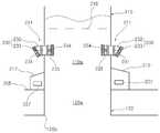
도 4는 본 발명의 2 실시예에 따른 데릭을 갖는 극지용 선박에 설치되는 댐퍼장치를 개략적으로 도시한 도면이고, 도 5는 도 4에서 데릭과 덕트가 연결되는 부분을 확대하여 도시한 도면이다.4 is a view schematically showing a damper device installed in a polar vessel having a derrick according to an embodiment of the present invention, Figure 5 is an enlarged view showing a portion where the derrick and the duct in Figure 4 is connected. .
도 4 및 도 5에 도시된 바와 같이, 본 발명의 2 실시예에 따른 데릭을 갖는 극지용 선박은 외부 공기와 차단되도록 밀폐된 공간을 형성하는 데릭(110)과 밀폐된 데릭(110)의 하부에 데릭과 소통되도록 연결시켜 외부 공기와 차단되도록 형성된 문풀(120)을 포함한다.4 and 5, the polar vessel having a derrick according to the second embodiment of the present invention is a lower portion of the
밀폐된 데릭(110)은 내부에 제1내부공간(110a)이 형성되고, 문풀(120)은 내부에 제2내부공간(120a)이 형성되어 상기 제1, 2 내부공간(110a, 120a)들이 소통하도록 연결되고, 데릭(110)은 선박의 드릴 플로어(205)의 상부에 배치되며, 상기 문풀(120)은 드릴 플로어(205)의 하부에 배치되도록 구성하였다.The sealed
데릭(110)은 외측벽이 밀폐된 구조로 구성되고, 데릭(110)의 측면에는 제1, 2 밀폐형 터널(217, 219)이 구비되며, 각 상기 제1, 2상기 밀폐형 터널(217, 219)의 단부에는 라이저 등과 같은 장비가 인입될 수 있는 개구가 형성된다.The
한편, 문풀(120)의 하부에는 입출구(120b)가 형성되고, 입출구(120b)를 통해 해수의 파도가 전달될 수 있으며, 이러한 파도영향으로 인해 상기 제1, 2 내부공간(110a, 120a)에 음압 또는 양압이 과도하게 발생될 수 있다.On the other hand, the entrance and exit (120b) is formed in the lower portion of the
이에, 본 발명은 밀폐된 데릭(110)의 적어도 일측면에 하나 이상의 공기출입장치로서 댐퍼장치(211)를 설치할 수 있고, 댐퍼장치(211)에 의해 제1 내부공간(110a)으로 공기가 유입 내지 배출됨에 따라 상기 제1, 2 내부공간(110a, 120a)에서 발생하는 과도한 음압 또는 양압을 보상 내지 상쇄할 수 있고, 이를 통해 상기 제1, 2 내부공간(110a, 120a)의 압력이 일정하게 유지될 수 있으므로 내부장비, 작업자, 작업환경을 안전하게 보호할 수 있다.Accordingly, the present invention may install the
댐퍼장치(211)는 밀폐된 데릭(110)의 측면에 설치되어 데릭(110)의 외부공간과 내부공간을 소통시키는 하나 이상의 소통덕트(230)와 소통덕트(230)를 개폐하는 개폐댐퍼(235)로 구성될 수 있으며. 소통덕트(230)의 외부공간측 단부는 하향 경사지게 형성할 수 있다.
소통덕트(230)는 굴곡형의 굴곡덕트(232)와 직관형의 관통덕트(233)로 구성될 수 있으며, 이러한 굴곡덕트(232)와 관통덕트(233)에는 굴곡덕트(32)와 관통덕트(33)를 선택적으로 개폐하는 개폐댐퍼(235)가 설치될 수 있다.The
특히, 댐퍼장치(211)는 핑거보드(216)의 하측에 위치하고, 이를 통해 상기 제1, 2 내부공간(110a, 120a)에 대한 압력 보상 및 상쇄 작동을 보다 원활하게 구현할 수 있다.In particular, the
소통덕트(230)의 양단부 중 적어도 하나 이상에는 망체를 설치할 수 있는데, 도 5에서는 양단부에 망체(231, 234)를 설치한 것으로 도시하였으며, 소통덕트(230)의 내부공간측 단부에 설치되는 망체(234)의 전단에 개폐댐퍼(235)를 설치할 수 있다.At least one of both ends of the
굴곡덕트(232)의 외부측 단부는 하향 경사져셔 밀폐된 데릭(110)을 외부공간과 소통케하고, 관통덕트(233)의 내부측 단부는 제1 내부공간(110a)과 소통하고, 관통덕트(233)의 내부측 단부에는 망체(234)가 설치될 수 있고, 관통덕트(233)의 내부측 단부와 망체(234) 사이에 개폐댐퍼(235)가 설치될 수 있다. 이러한 망체(231, 234)에 의해 외부 이물질 등의 유입을 최소화할 수 있다.The outer end of the bending
굴곡덕트(232)의 내부측 단부에는 관통덕트(233)가 연결되며, 관통덕트(233)는 데릭(10)의 측벽에 고정되는 것이 바람직하다.The through
개폐댐퍼(235)는 내부에 과도한 양압(25㎩ 초과) 및 음압(-75㎩ 미만) 발생시 압력 상쇄를 위해 수동 또는 자동으로 개폐할 수 있으며, 화재 또는 비상사태 발생 시에 공기의 흐름을 차단하도록 선택적으로 폐쇄작동할 수 있다.The opening and
그리고, 데릭(110)의 일측에는 개폐댐퍼(235)의 개폐작동을 제어하는 제어유닛(237)이 설치되고, 제어유닛(237)은 제1, 2 밀폐형 터널(217, 219) 측에 설치될 수도 있다. 이러한 제어유닛(237)은 데릭(110) 내의 압력 상태를 실시간으로 감지하여 개폐댐퍼(125)의 개폐작동을 수동 또는 자동 제어함으로써 상기 밀폐형 데릭(110) 내외로 공기를 유입 내지 배출하여 데릭(110) 내의 압력을 조절하도록 제어할 수 있다.And, the
이상과 같은 본 발명에 의하면, 문풀(120) 측으로 전달되는 파도영향으로 인한 밀폐된 데릭(110) 및 문풀(120) 내에서 발생하는 음압 또는 양압 등을 효과적으로 보상 내지 상쇄함으로써 밀폐된 데릭(110) 및 문풀(120) 내의 내부장치, 작업자, 작업환경을 안전하게 보호할 수 있는 장점이 있다.According to the present invention as described above, the sealed
또한, 본 발명은 하부로 경사진 굴곡덕트(232)와, 망체(231, 234)를 통해 외부의 빗물, 이물질 등의 유입이 최소화될 수 있는 장점이 있다.In addition, the present invention has an advantage that the inflow of external rainwater, foreign matters, etc. through the bending
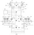
도 6은 본 발명의 3 실시예에 따른 데릭을 갖는 극지용 선박의 온도 및 압력 모니터링 시스템을 개략적으로 도시한 도면이다.FIG. 6 is a schematic diagram of a temperature and pressure monitoring system of a polar vessel having a derrick according to an embodiment of the present invention.
본 발명의 3 실시예에 따른 데릭을 갖는 극지용 선박은, 극지용 선박의 드릴 플로어(305) 상면에 밀폐된 데릭(110)을 설치하고, 밀폐된 데릭(110)의 하부에 문풀(120)을 구비한다.Polar ship having a derrick according to the third embodiment of the present invention, installed a sealed
도 6에 도시된 바와 같이, 본 발명의 3 실시예에 따른 데릭을 갖는 극지용 선박은 데릭 내부의 온도 및 압력을 모니터링하기 위해 하나 이상의 온도센서(351, 352, 353) 및 압력센서(354)를 설치할 수 있다.As shown in FIG. 6, a polar vessel having a derrick according to an embodiment of the present invention includes one or
또한, 온도센서(351, 352, 353) 및 압력센서(354)에 의해 모니터링된 온도 및 압력을 근거로 하여 데릭(110) 또는 문풀(120) 내부공간(110a, 120a)의 공기조건을 일정범위로 유지하거나, 제어할 수 있도록 내부공간(100a, 120a)에 대해 외부 공기를 주입 또는 배출하는 제어유닛(355)을 추가설치할 수 있다.In addition, based on the temperature and pressure monitored by the
데릭(110)은 내부에 제1 내부공간(110a)이 형성되고, 문풀(120)은 내부에 제2 내부공간(120a)이 형성되어 상기 제1, 2 내부공간(110a, 120a)들이 상호 소통하도록 연결되고, 데릭(110)은 선박의 드릴 플로어(305)의 상부에 배치되며, 문풀(120)은 드릴 플로어(305)의 하부에 배치된다.The
데릭(110)은 외측벽이 밀폐된 구조로 구성되고, 밀폐된 데릭(110)의 측면에는 제1, 2 밀폐형 터널(317, 319)이 구비되며, 제1, 2 밀폐형 터널(317, 319)의 각 단부에는 라이저 등과 같은 장비가 인입될 수 있는 개구가 형성된다.The
밀폐된 데릭(110)의 외측에는 밀폐된 데릭(110) 및 문풀(120)의 외측에서 외부공기를 제1 내부공간(110a) 및 상기 제2 내부공간(120a)으로 공급하는 공급유닛(340)이 설치될 수 있다.Outside the sealed
공급유닛(340)은 드릴 플로어(305)의 외측에 설치되는 하나 이상의 유입구(341), 상기 유입구(341)에 연결되는 하나 이상의 공급팬(342), 상기 유입구(341)에 인접하여 설치된 하나 이상의 히터(343), 상기 공급팬(342)의 하류 측에 설치되어 외부공기의 유입을 선택적으로 개폐하는 하나 이상의 개폐밸브(344)로 구성될 수 있다.The
공급팬(342)은 유입구(341)의 하부에 연결되어 외부공기를 제2 내부공간(120a)으로 강제 송풍하도록 구성될 수 있고, 공급팬(342)에 의해 강제 송풍 되는 외부공기는 수공관(345)을 통해 제2 내부공간(120a) 또는 제1 내부공간(110a) 하측으로 공급될 수 있다.
히터(343)는 극한지방에서 온도가 낮은 경우(0℃ 이하)에 유입구(341)를 통해 유입되는 외부공기를 가열하고, 가열된 공기가 제1, 2 내부공간(110a, 120a)으로 공급팬(342)에 의해 유입되므로 내부장비, 작업자, 작업환경을 외부의 극한환경으로부터 안전하게 보호 및 유지할 수 있다.The
개폐밸브(344)는 화재 또는 비상시, 공급팬(342)의 보수 시에 공기의 흐름을 차단하도록 선택적으로 개폐작동할 수 있다.The opening and closing
그리고 공급유닛(340)에 의해 제2 내부공간(120a)으로 외부공기가 유입됨에 따라 제2 내부공간(120a)에서 제1 내부공간(110a) 상측으로 공기가 상승하도록 유도하는 배기유닛(330)이 데릭(110)의 상부에 설치될 수 있다.And as the outside air flows into the second inner space (120a) by the
배기유닛(330)은 데릭(110)의 상부에 설치된 하나 이상의 배기구(331), 배기구(331)에 연결된 하나 이상의 배기팬(332)을 포함할 수 있다.The
배기팬(332)은 크라운 블록부(313) 내에 설치될 수 있고, 배기팬(332)에는 개폐밸브(333)가 연결되어 설치되며, 개폐밸브(333)는 화재 또는 비상시, 배기팬(332)의 보수 시에 공기의 흐름을 차단하도록 선택적으로 개폐작동할 수 있다.
문풀(120)의 하부에는 입출구(120b)가 형성되고, 입출구(120b)를 통해 해수의 파도가 전달될 수 있으며, 파도의 영향으로 인해 제1, 2 내부공간(110a, 120a)에 음압 또는 양압이 과도하게 발생될 수 있다.Inlet and outlet (120b) is formed in the lower portion of the
이에, 데릭(110)의 적어도 일측면에 하나 이상의 댐퍼장치(311)를 설치하고, 댐퍼장치(311)에 의해 제1 내부공간(110a)으로 공기가 유입 내지 배출됨으로써 제1, 2 내부공간(110a, 120a)에서 발생하는 과도한 음압 또는 양압을 보상 내지 상쇄할 수 있게 된다.Accordingly, at least one
이를 통해 제1, 2 내부공간(110a, 120a)의 압력이 일정하게 유지될 수 있으므로 내부장비, 작업자, 작업환경을 안전하게 보호될 수 있다.Through this, the pressure in the first and second
댐퍼장치(311)은 도 5에 도시된 2 실시예에서 설명한 바와 같이, 데릭(110)의 측면에 설치되어 데릭(110)의 외부공간과 내부공간을 소통시키는 하나 이상의 소통덕트(321), 소통덕트(321)에 연결되어 소통덕트(321)를 선택적으로 개폐하는 개폐밸브(322)로 구성될 수 있다.The
온도센서(351, 352, 353)는 제1 내부공간(110a)에 설치되어 내부 온도를 모니터링하고, 압력센서(354)는 제2 내부공간(120a)에 설치되어 내부의 압력차이를 모니터링하도록 구성된다.The
온도센서(351, 352, 353)는 제1 내부공간(110a) 상측에 설치된 제1온도센서(351), 제1 내부공간(110a) 중간에 설치되는 제2 온도센서(352), 제1 내부공간(110a) 하측에 설치되는 제3 온도센서(353)로 구성될 수 있다.The
제1 온도센서(351)는 데릭(110)의 상부에 설치된 배기유닛(330)과 인접하여 배치될 수 있으며, 특히, 데릭(110)의 상부에는 상부보드(314)가 배치되다면, 상부보드(314)의 상측에 제1 온도센서(351)가 설치될 수 있다.The
제2 온도센서(352)는 데릭(110)의 핑거보드(316) 상측에 설치될 수 있으며, 제3 온도센서(353)는 데릭(110)의 핑거보드(316)와 드릴 플로어(305) 사이에 설치될 수 있다.The
이와 같이, 본 발명의 3 실시예에 따른 데릭을 갖는 극지용 선박은 제1 내지 제3 온도센서(351, 352, 353)가 제1 내부공간(110a)의 3층으로 구획된 부분에 각각 설치됨에 따라 제1 내부공간(110a)에 대한 온도를 정확하게 측정 내지 모니터링할 수 있다.As described above, in the polar ship having a derrick according to the third embodiment of the present invention, the first to
그리고 압력센서(354)는 제2 내부공간(120a)에 설치되어 제2 내부공간(120a)에서 발생하는 압력차이를 정밀하게 측정 내지 모니터링하도록 구성될 수 있으며, 파도의 영향으로 인해 발생하는 과도한 제2 내부공간(120a)의 음압 또는 양압을 압력센서(354)가 정밀하게 측정 내지 모니터링하여 제2 내부공간(120a)에서의 압력의변동을 정밀하게 측정 내지 모니터링하게 된다.In addition, the
이와 같이, 본 발명의 3 실시예에 따른 데릭을 갖는 극지용 선박은 제1 내지 제3 온도센서(351, 352, 353) 및 압력센서(354)를 통해 통풍을 위한 공급유닛(340) 및 배기유닛(330)과 압력보상을 위한 댐퍼장치(311)의 운전 이상 여부를 정확하게 확인할 수 있게 된다.As such, the polar ship having a derrick according to the third embodiment of the present invention has a
또한, 본 발명의 3 실시예에 따른 데릭을 갖는 극지용 선박은 제1 내지 제3 온도센서(351, 352, 353) 및 압력센서(354)를 통해 모니터링된 온도 및 압력 정보에 따라 공급유닛 및 배기유닛과 댐퍼장치(311)를 정밀하게 작동되도록 제어할 수 있어, 제1, 2 내부공간(110a, 120a)에서의 이상 온도 및 이상 압력의 위험에 효과적으로 대처하고, 이를 통해 데릭(110) 및 문풀(120) 내의 작업자, 장비, 작업환경에 대한 안정성을 확보할 수 있도록 한다.In addition, the polar vessel having a derrick according to the third embodiment of the present invention is the supply unit and the temperature and pressure information monitored through the first to
여기서 일예로, 제1, 2 내부공간(110a, 120a)에서의 이상 온도에 대한 대처는 제1, 2 내부공간(110a, 120a)의 내부 온도가 -20℃ ~ 45℃를 유지할 수 있도록 제1 내지 제3 온도센서(351, 352, 353)의 온도 모니터링 값에 따라 히터(343), 공급유닛(340), 배기유닛(330) 또는 댐퍼장치(311)의 작동을 정밀하게 제어할 수 있는데, 주로 댐퍼장치(311)의 작동을 제어한다.Here, for example, in response to the abnormal temperature in the first and second
또한, 제1, 2 내부공간(110a, 120a)에서의 이상 압력에 대한 대처는 제1, 2 내부공간(110a, 120a)의 내부 압력을 환경 조건(파도 및 외부 온도)에 따라 정상적인 경우와 비정상적인 경우(극지방, 태풍 등)로 나누어 대처하게 된다.In addition, in response to the abnormal pressure in the first and second
먼저, 정상적인 경우 제1, 2 내부공간(110a, 120a)의 압력을 -25pa을 유지하도록 하고, 비정상적인 경우 -75pa ~ 25pa을 유지하도록 하는 것이 좋다. 이때, 압력 유지 수단은 댐퍼장치(311)의 작동을 제어하는 것인데, 댐퍼장치(311)는 수동 또는 자동으로 조정할 수 있다.First, in the normal case, the pressure of the first and second
더불어 공급팬(342), 히터(343), 개폐밸브(344), 공급유닛(340), 배기유닛(330), 댐퍼장치(311), 온도센서(351, 352, 353) 또는 압력센서(354)를 자동으로 제어하기 위해 제어유닛(355)을 선박에 설치하여 각 장치들과 접속되게 할 수도 있다.In addition,
도 7은 본 발명의 4 실시예에 따른 데릭을 갖는 극지용 선박의 데릭구조를 도시한 사시도이고, 도 8는 본 발명의 4 실시예에 따른 데릭을 갖는 극지용 선박의 데릭구조 및 이에 설치된 통풍장치를 도시한 단면도이다.7 is a perspective view showing the derrick structure of the polar ship having a derrick according to the fourth embodiment of the present invention, Figure 8 is a derrick structure of the polar ship having a derrick according to the fourth embodiment of the present invention and ventilation installed therein It is sectional drawing which shows apparatus.
본 발명의 4 실시예에 따른 데릭을 갖는 극지용 선박은, 극지용 선박의 드릴 플로어(405) 상면에 밀폐된 데릭(110)을 설치하고, 밀폐된 데릭(110)의 하부에 문풀(120)을 구비한다. 데릭(110)으로부터 문풀(120) 까지는 밀폐된 구조로 연결되는데, 데릭(110)과 문풀(120)은 각 내부공간(110a, 120a)들이 소통하도록 연결되고, 밀폐된 데릭(110)은 선박의 드릴플로어(405)의 상부에 배치되며, 밀폐된 문풀(120)은 드릴플로어(405)의 하부에 배치된다.Polar ship having a derrick according to the fourth embodiment of the present invention, installed a sealed
삭제delete
밀폐된 데릭(110)은 외측벽이 밀폐된 구조로 구성되어 있는데, 외측벽은 FRP(fiberglass reinforced polymer), 스테인레스 시트(SUS sheet), 아연도금 구조물 또는 샌드위치판낼(sandwich panel)로 이루어질 수 있다.The sealed
그리고 밀폐된 데릭(10)의 측면에는 밀폐형 터널(417, 419)이 구비되며, 각 밀폐형 터널(417, 419)의 단부에는 라이저 등과 같은 장비가 인입될 수 있는 개구가 형성되고, 밀폐형 터널(417, 419)은 라이저 텐셔너 룸(416, riser tensioner room)과 인접한다.And the side of the sealed
그리고 데릭(10)의 외측에는 데릭(10)의 외측에서 밀폐된 데릭의 내부공간(110a) 또는 문풀의 내부공간(120a)으로 외부공기를 공급하는 공급유닛(440)이 설치된다.And the outside of the
공급유닛(440)은 드릴플로어(405)의 외측에 설치되는 하나 이상의 유입구(441), 유입구(441)에 연결되는 하나 이상의 공급팬(442), 유입구(441)에 인접하여 설치된 하나 이상의 히터(443), 공급팬(442)의 하류 측에 설치되어 외부공기의 유입을 선택적으로 개폐하는 하나 이상의 개폐밸브(444)로 구성될 수 있다.The
유입구(441)는 라이저 텐셔너 룸(416)의 루프(413)측에 설치될 수 있으며, 유입구(441)를 통해 외부공기가 유입된다.The
공급팬(442)은 유입구(441)의 하부에 연결되어 외부공기를 밀폐된 문풀의 내부공간(120a)으로 강제 송풍하도록 구성될 수 있고, 공급팬(442)에 의해 강제 송풍 되는 외부공기는 수공관(445)을 통해 밀폐된 문풀의 내부공간(120a) 또는 밀폐된 데릭의 내부공간(110a) 하측으로 공급될 수 있다.
히터(443)는 극한지방에서 그 온도가 낮은 경우(특히, 겨울철에 준하는 온도로 0℃ 이하)에 유입구(441)를 통해 유입되는 외부공기를 가열하고, 가열된 공기가 문풀(15) 및 데릭(10)의 내부공간(15a, 10a)으로 공급팬(442)에 의해 유입되어 내부장비, 작업자, 작업환경을 외부의 극한환경으로부터 안전하게 보호 및 유지될 수 있다.The
개폐밸브(444)는 화재 또는 비상시, 공급팬(442)의 보수 시에 공기의 흐름을 차단하도록 선택적으로 개폐작동할 수 있다.The opening and closing
한편, 공급유닛(440)에 의해 문풀의 내부공간(120a)으로 외부공기가 유입됨에 따라 밀폐된 문풀의 내부공간(120a)에서 밀폐된 데릭의 내부공간(110a) 상측으로 공기가 상승하도록 유도하는 배기유닛(430)이 데릭(10)의 상단에 설치될 수 있다.On the other hand, as the outside air flows into the
밀폐된 데릭(110)의 상부는 크라운 블록부(420)를 이루고, 크라운 블록부(420)는 내부에 크라운 블록(미도시, crown block)을 설치하며, 상부로 갈수록 그 폭이 넓어지는 구조로 구성되어 내부에 설치작업공간(450)을 형성할 수 하였으며, 설치작업공간(450)도 상단으로 갈수록 폭이 넓어지도록 형성된다.The upper part of the sealed
특히, 크라운 블록부(420)의 적어도 일측면에 경사면(421)이 구비되고, 상기 경사면(421)에는 배기유닛(430)이 설치될 수 있으며, 도 7 및 도 8에는 크라운 블록부(420)의 양측면에 한 쌍의 경사면(421)이 대칭적으로 형성되도록 하였고, 각 경사면(421)에 배기유닛(430)을 설치하도록 하였다.In particular, an
설치작업공간(450)은 하측으로 데릭의 내부공간(110a)과 소통하며, 하측을 가로지르게 크라운 블록 플렛폼(425)이 설치되고, 크라운 블록 플렛폼(25)의 상면에 크라운 블록(미도시)이 설치되도록 한다.The
이와 같이, 본 발명의 4 실시예에 따른 데릭을 갖는 극지용 선박은 밀폐된 데릭(110)의 상단에 상측 폭이 넓어지는 구조의 크라운 블록부(420)가 설치됨에 따라, 내부에 형성되는 설치작업공간(450)이 상측으로 넓어지는 형상을 형성할 수 있다.As such, the polar ship having a derrick according to the fourth embodiment of the present invention is installed inside the
이에 따라, 설치작업공간(450)은 설치작업공간(450)에 설치되는 크라운 블록 플렛폼(425)을 활용하여 배기유닛(430)을 크라운 블록부(420)의 측면에 설치하고 유지 및 보수 작업을 할 수 있는 충분한 공간을 제공할 수 있다. 따라서, 작업자의 유지 및 보수 작업이 효과적이고 안전하게 진행될 수 있다.Accordingly, the
이렇게 데릭(110)의 상부에 배기유닛(430)을 설치함으로써, 밀폐된 데릭(110) 및 문풀(120) 내의 공기흐름이 매우 효율적으로 이루어져 내부장비, 작업자, 작업환경의 안정적인 보호 및 유지가 효과적으로 구현될 수 있다.By installing the
배기유닛(430)은 경사면(421) 측에 설치된 하나 이상의 배기구(431), 배기구(431)에 연결된 하나 이상의 배기팬(432)으로 구성될 수 있다.The
배기팬(432)은 크라운 블록(420) 내에 설치되고, 또한 배기팬(432)에는 개폐밸브(433)가 연결되어 설치되며, 개폐밸브(433)는 화재 또는 비상시, 배기팬(432)의 보수 시에 공기의 흐름을 차단하도록 선택적으로 개폐작동할 수 있다.
이상과 같이, 본 발명의 4 실시예에 따른 데릭을 갖는 극지용 선박은 밀폐된데릭(110)의 상단에 상부로 갈수록 폭이 넓어지는 크라운 블록부(420)가 구비됨에 따라 추가적인 덕트(duct) 설치 작업 없이 크라운 블록 플렛폼(425)을 활용함과 동시에 배기유닛(430)의 설치를 위한 충분한 작업공간을 부여할 수 있고, 이를 통해 밀폐된 데릭(110)의 상단에 배기유닛(430)의 설치 및 유지, 보수를 보다 효과적으로 수행함과 더불어 작업자의 안전성을 향상시킬 수 있다.As described above, the polar vessel having a derrick according to the fourth embodiment of the present invention is provided with an additional duct as the
그리고 본 발명의 4 실시예에 따른 데릭을 갖는 극지용 선박은 밀폐된 문풀(120) 측으로 외부공기를 공급하고 밀폐된 데릭(110)의 상부에서 배기하도록 함으로써 밀폐된 문풀(120)에서 밀폐된 데릭(110)의 상부로 공기의 흐름이 원활하게 이루어지므로, 밀폐된 데릭(110) 내의 내부 장비, 작업자, 작업환경을 외부의 극한환경으로부터 보다 안전하게 보호 및 유지할 수 있는 장점이 있다.And the polar ship having a derrick according to the fourth embodiment of the present invention is supplied to the outside air to the sealed
상술한 본 발명의 각 실시예에 따른 데릭을 갖는 극지용 선박은 기술의 편이상 실시예별로 기술구성을 달리 표현하였으나, 각 실시예들의 기술구성에서 다른 기능을 보유한 구성들을 종합하여 별도로 다른 실시예를 구성할 수도 있음은 자명하다.Polar ship having a derrick according to each embodiment of the present invention described above, but the technical configuration is expressed differently by one or more embodiments of the technology, a separate embodiment by combining the configurations having different functions in the technical configuration of each embodiment It is obvious that it can also be configured.
그리고, 본 발명은 상기 실시예에 한정되지 않고 본 발명의 기술적 요지를 벗어나지 아니하는 범위 내에서 다양하게 수정 또는 변형되어 실시될 수 있음은 본 발명이 속하는 기술분야에서 통상의 지식을 가진 자에 있어서 자명한 것이다.
In addition, the present invention is not limited to the above embodiments and can be implemented in various modifications or variations without departing from the technical gist of the present invention in those skilled in the art to which the present invention pertains. It is self-evident.
100: 극지용 선박110: 데릭
110a: 제1 내부공간111: 댐퍼장치
120: 문풀(moonpool)120a: 제2 내부공간
120b: 입출구130: 공급유닛
131: 공급팬(supply fan)132: 유입루버(louver)
133: 개폐밸브134: 히터
136: 수송관(duct)137: 와이어 메시(wire mesh)
140: 배기유닛141: 배기팬(exhuast fan)
142: 유입루버(louver)143: 개폐밸브
150: 공기 유입부160: 열 송풍기(heat blower)
205: 드릴플로어211: 댐퍼장치
216: 핑거보드217: 제1 밀폐형 터널
219: 제1, 2 밀폐형 터널
231, 234: 망체230: 소통덕트
232: 굴곡덕트233: 관통덕트
235: 개폐댐퍼237: 제어유닛
305: 드릴플로어311: 댐퍼장치
313: 크라운블락부314: 상부보드
316: 핑거보드317: 제1 밀폐형 터널
319: 제2 밀폐형 터널330: 배기유닛
331: 배기구332: 배기팬
333: 개폐밸브340: 공급유닛
341: 유입구342: 공급팬
343: 히터344: 개폐밸브
345: 공급배관351, 352, 353: 온도센서
354: 압력센서355: 제어유닛
405: 드릴플로어411: 댐퍼장치
413: 루프416: 라이저 텐셔너 룸
417, 419: 밀폐형 터널420: 크라운 블록부
421: 경사면425: 크라운 블록 플랫폼
430: 배기유닛431: 배기구
32: 배기팬433: 개폐밸브
440: 공급유닛441: 유입구
442: 공급팬443: 히터
444: 개폐밸브445: 수송관
450: 설치작업공간100: Polar Vessel 110: Derrick
110a: first internal space 111: damper device
120: moonpool 120a: second interior space
120b: inlet and outlet 130: supply unit
131: supply fan 132: inlet louver
133: on-off valve 134: heater
136: duct 137: wire mesh
140: exhaust unit 141: exhaust fan (exhuast fan)
142: louver 143: on-off valve
150: air inlet 160: heat blower
205: drill floor 211: damper device
216: fingerboard 217: first closed tunnel
219: first and second sealed tunnels
231, 234: network 230: communication duct
232: bending duct 233: through duct
235: opening and closing damper 237: control unit
305: drill floor 311: damper device
313: crown block portion 314: upper board
316: fingerboard 317: first closed tunnel
319: second sealed tunnel 330: exhaust unit
331: exhaust port 332: exhaust fan
333: on-off valve 340: supply unit
341: inlet 342: supply fan
343: heater 344: on-off valve
345: supply piping 351, 352, 353: temperature sensor
354: pressure sensor 355: control unit
405: drill floor 411: damper device
413: Loop 416: Riser Tensioner Room
417, 419: enclosed tunnel 420: crown block portion
421: slope 425: crown block platform
430: exhaust unit 431: exhaust port
32: exhaust fan 433: on-off valve
440: supply unit 441: inlet
442: supply fan 443: heater
444: on-off valve 445: transport pipe
450: installation workspace
Claims (20)
Translated fromKorean상기 데릭으로부터 상기 문풀 까지는 밀폐구조로 구성되며,
상기 공기출입장치에 의해 상기 내부공간의 공기조건이 일정범위를 유지하거나 제어될 수 있도록 하는 구성인 것을 특징으로 하는 데릭을 갖는 극지용 선박.A polar vessel having a derrick, said derrick forming a closed space isolated from outside air; A moonpool connected below the derrick in communication with the derrick and blocked from outside air; And an air access device installed to communicate the interior space of the derrick or the door pool and the outside.
The derrick to the door pool is composed of a closed structure,
The polar ship having a derrick, characterized in that the air conditioner is configured to maintain or control the air condition of the internal space by a certain range.
상기 공기출입장치는,
상기 데릭 또는 상기 문풀에 외부 공기를 공급하는 공급유닛; 및
공급된 공기를 상기 데릭 상부에서 배출하는 배기유닛;을 포함하는 것을 특징으로 하는 데릭을 갖는 극지용 선박.The method according to claim 1,
The air inlet device,
A supply unit for supplying external air to the derrick or the door pool; And
And an exhaust unit for discharging the supplied air from the upper part of the derrick.
상기 공급유닛은 공급되는 외부 공기에 열원을 가할 수 있는 히터;를 포함하는 것을 특징으로 하는 데릭을 갖는 극지용 선박.The method according to claim 2,
The supply unit is a polar ship having a derrick comprising a; heater that can apply a heat source to the supplied outside air.
상기 공급유닛 및 배기유닛 중 적어도 하나 이상에는 공급 또는 배출되는 공기의 흐름을 개폐하는 개폐밸브를 포함하는 것을 특징으로 하는 데릭을 갖는 극지용 선박.The method according to claim 2,
At least one or more of the supply unit and the exhaust unit polar ship having a derrick, characterized in that it comprises an opening and closing valve for opening and closing the flow of air to be supplied or discharged.
상기 공급유닛 및 배기유닛 중 적어도 하나 이상에는 공기 이외의 입자가 유입되는 것을 방지하기 위한 유입 루버(louver)가 형성되는 것을 특징으로 하는 데릭을 갖는 극지용 선박.The method according to claim 2,
At least one or more of the supply unit and the exhaust unit polar ship having a derrick, characterized in that the inlet louver (louver) for preventing the inflow of particles other than air is formed.
상기 공기출입장치는,
상기 데릭에 외부 공기가 유입될 수 있는 개폐가능한 공기유입부;를 더 포함하는 것을 특징으로 하는 데릭을 갖는 극지용 선박.The method according to claim 2,
The air inlet device,
A polar ship having a derrick further comprising; an openable air inlet for allowing external air to flow into the derrick.
상기 데릭의 내부에는 공기를 가열하여 통풍을 원활하게 할 수 있는 열 송풍기(heat blower)가 구비된 것을 특징으로 하는 데릭을 갖는 극지용 선박.The method according to claim 2,
The polar ship having a derrick, characterized in that the inside of the derrick is provided with a heat blower (heat blower) capable of smoothly ventilating by heating the air.
상기 공급유닛에는 공급팬(supply fan)이 설치되고 상기 배기유닛에는 배기팬(exhaust fan)이 설치되며;
상기 공급팬과 상기 배기팬은 외부 공기의 온도에 따라서 작동속도를 달리하는 것을 특징으로 하는 데릭을 갖는 극지용 선박.The method according to claim 2,
A supply fan is installed in the supply unit and an exhaust fan is installed in the exhaust unit;
Wherein the supply fan and the exhaust fan polar ship having a derrick, characterized in that the operating speed varies according to the temperature of the outside air.
상기 공급유닛에 의해 공급되는 외부 공기를 상기 데릭 또는 상기 문풀로 전달하는 수송관(duct);을 포함하되,
상기 데릭 또는 상기 문풀과 만나는 상기 수송관의 말단에는 와이어 메시(wire mesh);가 형성된 것을 특징으로 하는 데릭을 갖는 극지용 선박.The method according to claim 2,
Includes; a transport pipe (duct) for delivering the outside air supplied by the supply unit to the derrick or the door pool;
A polar ship having a derrick, characterized in that a wire mesh; is formed at the end of the transport pipe that meets the derrick or the door pool.
상기 공기출입장치는,
상기 데릭의 적어도 일측면에 설치되어 상기 데릭 내로 공기를 선택적으로 유입 또는 배출시키는 댐퍼장치;를 포함하는 것을 특징으로 하는 데릭을 갖는 극지용 선박.The method according to claim 1,
The air inlet device,
And a damper device installed on at least one side of the derrick to selectively introduce or discharge air into the derrick.
상기 댐퍼장치는,
상기 데릭의 외부공간과 내부공간을 소통시키는 하나 이상의 소통덕트; 및
상기 소통덕트에 연결되고, 상기 소통덕트를 개폐하는 개폐댐퍼를 포함하는 것을 특징으로 하는 데릭을 갖는 극지용 선박.The method of claim 10,
The damper device,
At least one communication duct for communicating the outer space and the inner space of the derrick; And
Connected to the communication duct, polar ship having a derrick, characterized in that it comprises an opening and closing damper for opening and closing the communication duct.
상기 소통덕트의 양단부 중 적어도 하나 이상에는 망체;를 설치하되,
상기 소통덕트의 내부공간측 단부에 설치되는 망체의 전단에는 상기 개폐댐퍼를 설치하고, 상기 소통덕트의 외부공간측 단부는 하향 경사지게 형성하는 것을 특징으로 하는 데릭을 갖는 극지용 선박.The method of claim 11,
At least one of both ends of the communication duct;
The polar vessel having a derrick, characterized in that the front and rear dampers are installed in the front end of the network is installed at the end of the communication duct, the outer space side end of the communication duct is formed to be inclined downward.
상기 개폐댐퍼의 개폐작동을 제어하는 제어유닛;을 더 포함하되,
상기 데릭의 상부 내측에는 핑거보드가 형성되고, 상기 댐퍼장치는 상기 핑거보드 하측에 위치하는 것을 특징으로 하는 데릭을 갖는 극지용 선박.The method of claim 11,
Further comprising; a control unit for controlling the opening and closing operation of the opening and closing damper;
A fingerboard is formed inside the upper part of the derrick, and the damper device is a polar vessel having a derrick, characterized in that located below the fingerboard.
상기 데릭의 내부에 설치되어 내부 온도를 모니터링하는 하나 이상의 온도센서;
상기 문풀의 내부에 설치되어 내부 압력을 모니터링하는 하나 이상의 압력센서; 및
상기 온도센서 및 압력센서에 의해 모니터링된 내부 온도 및 압력 정보를 통해 상기 공급유닛 및 배기유닛의 작동을 제어하는 제어유닛;을 포함하는 것을 특징으로 하는 데릭을 갖는 극지용 선박.The method according to claim 2,
One or more temperature sensors installed inside the derrick to monitor internal temperatures;
One or more pressure sensors installed inside the door pool to monitor internal pressure; And
And a control unit for controlling the operation of the supply unit and the exhaust unit through the internal temperature and pressure information monitored by the temperature sensor and the pressure sensor.
상기 온도센서는,
상기 데릭의 상부에 설치된 제1온도센서;
상기 데릭의 중간에 설치되는 제2온도센서; 및
상기 데릭의 하부에 설치되는 제3온도센서;로 구성되는 것을 특징으로 하는 데릭을 갖는 극지용 선박.The method of claim 14,
Wherein the temperature sensor comprises:
A first temperature sensor installed above the derrick;
A second temperature sensor installed in the middle of the derrick; And
The polar ship having a derrick, characterized in that consisting of; a third temperature sensor installed in the lower portion of the derrick.
상기 데릭의 상부 내부 측면에 형성된 배기유닛; 및
상기 데릭의 중부 내부를 가로지르게 형성된 핑거보드;를 포함하되,
상기 제1온도센서는 상기 배기유닛과 인접하여 배치되고, 상기 제2온도센서는 상기 핑거보드 상측에 배치되며, 상기 제3온도센서는 상기 데릭의 핑거보드 하측에 배치되는 것을 특징으로 하는 데릭을 갖는 극지용 선박.The method of claim 15,
An exhaust unit formed at an upper inner side of the derrick; And
Including; a fingerboard formed to cross the inside of the middle of the derrick; including,
The first temperature sensor is disposed adjacent to the exhaust unit, the second temperature sensor is disposed above the fingerboard, and the third temperature sensor is disposed below the fingerboard of the derrick. Having polar vessels.
상기 밀폐된 데릭의 상부에 형성되어 내부에 크라운 블록(crown block)이 설치됨과 함께 설치작업공간이 형성되는 크라운 블록부;를 더 포함하되,
상기 공기출입장치는 상기 데릭 내부의 공기를 배출할 수 있는 배기유닛으로 구성되되, 상기 설치작업공간이 외부와 소통될 수 있도록 상기 크라운 블록부에 설치되는 것을 특징으로 하는 데릭을 갖는 극지용 선박.The method according to claim 1,
It is formed on the top of the sealed derrick and the crown block (crown block) is installed therein and the crown block portion is formed in the installation work space; further comprising,
The air inlet device is composed of an exhaust unit capable of discharging the air inside the derrick, the polar ship having a derrick, characterized in that installed in the crown block portion so that the installation work space can be communicated with the outside.
상기 데릭 또는 상기 문풀에 외부공기를 공급하는 공급유닛;을 더 포함하되,
상기 배기유닛 및 공급유닛에는 외부공기의 흐름을 개폐할 수 있는 개폐밸브;가 설치되는 것을 특징으로 하는 데릭을 갖는 극지용 선박.18. The method of claim 17,
Further comprising; supply unit for supplying external air to the derrick or the door pool,
The exhaust unit and the supply unit polar ship having a derrick, characterized in that; opening and closing valve for opening and closing the flow of external air is installed.
상기 크라운 블록부는 상단으로 갈수록 폭이 넓어지며, 상기 설치작업공간은 상단으로 갈수록 폭이 넓어지게 형성되는 것을 특징으로 하는 데릭을 갖는 극지용 선박.The method of claim 18,
The crown block portion is wider toward the top, the installation space is polar ship having a derrick, characterized in that the width is formed wider toward the top.
상기 크라운 블록부가 하단에 비해 상단의 둘레가 넓게 형성되도록 양측면에 한 쌍의 경사면이 대칭적으로 형성되는 것을 특징으로 하는 데릭을 갖는 극지용 선박.The method of claim 19,
Polar poles having a derrick, characterized in that the pair of inclined surfaces are formed symmetrically on both sides so that the crown block portion is formed in a wider circumference than the bottom.
Applications Claiming Priority (4)
| Application Number | Priority Date | Filing Date | Title |
|---|---|---|---|
| KR1020100072573 | 2010-07-27 | ||
| KR1020100072573 | 2010-07-27 | ||
| KR1020100109026 | 2010-11-04 | ||
| KR1020100109026 | 2010-11-04 |
Publications (2)
| Publication Number | Publication Date |
|---|---|
| KR20120010953A KR20120010953A (en) | 2012-02-06 |
| KR101364517B1true KR101364517B1 (en) | 2014-02-25 |
Family
ID=45530559
Family Applications (1)
| Application Number | Title | Priority Date | Filing Date |
|---|---|---|---|
| KR1020110029002AActiveKR101364517B1 (en) | 2010-07-27 | 2011-03-30 | Arctic ship with derrick |
Country Status (8)
| Country | Link |
|---|---|
| US (1) | US9376199B2 (en) |
| EP (1) | EP2599709B1 (en) |
| JP (2) | JP5739528B2 (en) |
| KR (1) | KR101364517B1 (en) |
| CN (1) | CN103269949B (en) |
| ES (1) | ES2629677T3 (en) |
| SG (1) | SG187206A1 (en) |
| WO (1) | WO2012015169A2 (en) |
Cited By (1)
| Publication number | Priority date | Publication date | Assignee | Title |
|---|---|---|---|---|
| KR20190062771A (en) | 2017-11-29 | 2019-06-07 | 대우조선해양 주식회사 | Vortex shedding reducing apparatus and arctic offshore structure |
Families Citing this family (9)
| Publication number | Priority date | Publication date | Assignee | Title |
|---|---|---|---|---|
| KR101213757B1 (en)* | 2010-11-19 | 2012-12-18 | 대우조선해양 주식회사 | System for the pressure and temperature monitoring of enclosed derrick structure |
| KR101524210B1 (en)* | 2014-01-16 | 2015-05-29 | 삼성중공업 주식회사 | Ship having emergency apparatus for exhausting gas |
| KR102338439B1 (en)* | 2015-11-11 | 2021-12-09 | 대우조선해양 주식회사 | Ventilation system for arctic condition |
| KR102196981B1 (en)* | 2016-07-20 | 2020-12-30 | 현대중공업 주식회사 | A drillship |
| KR102196980B1 (en)* | 2016-07-20 | 2020-12-30 | 현대중공업 주식회사 | A drillship |
| KR102196977B1 (en)* | 2016-07-20 | 2020-12-30 | 현대중공업 주식회사 | A drillship |
| CN109110098B (en)* | 2018-07-30 | 2021-04-16 | 中国舰船研究设计中心 | Closed mast internal air conditioning system for ship |
| KR102600607B1 (en)* | 2018-10-31 | 2023-11-09 | 한화오션 주식회사 | Air Conditioning System for Arctic Vessel |
| BR102019006241B1 (en)* | 2019-03-28 | 2023-12-19 | Odebrecht Óleo E Gás S.A. | SYSTEM AND METHOD FOR INSTALLING A DUCT WITH HIGH RADIUS OF CURVATURE AND LOW WEIGHT ON THE SEA BED |
Citations (3)
| Publication number | Priority date | Publication date | Assignee | Title |
|---|---|---|---|---|
| US4613001A (en)* | 1983-09-21 | 1986-09-23 | Gotaverken Arendal Ab | Weather protected offshore drilling rig |
| KR200431766Y1 (en)* | 2006-09-15 | 2006-11-24 | 삼성중공업 주식회사 | Local ventilation system of low temperature outdoor vessel |
| KR100686529B1 (en)* | 2006-06-30 | 2007-02-26 | 서광옥 | Vents for ship engine room |
Family Cites Families (41)
| Publication number | Priority date | Publication date | Assignee | Title |
|---|---|---|---|---|
| US2153350A (en)* | 1937-07-26 | 1939-04-04 | Stimac Emil | Auxiliary air intake for internal combustion engines |
| GB611961A (en) | 1946-05-14 | 1948-11-05 | Edward Frank Spanner | Improvements in ship ventilation |
| US2691272A (en) | 1950-09-23 | 1954-10-12 | Townsend Rex | Submersible oil well drilling rig |
| US2804951A (en) | 1955-07-11 | 1957-09-03 | Wonderly Construction Company | Well rig cover |
| US3093056A (en) | 1961-08-22 | 1963-06-11 | Morton M Rosenfeld | Ventilation system |
| US3279407A (en) | 1963-05-28 | 1966-10-18 | Stenger Jacob Johannes | Surface vessel |
| US3461828A (en) | 1968-04-15 | 1969-08-19 | Exxon Production Research Co | Floating drilling platform |
| US3593645A (en) | 1969-03-03 | 1971-07-20 | Connor Eng Corp | Terminal outlet for air distribution system |
| US3850125A (en) | 1971-09-24 | 1974-11-26 | Global Marine Inc | Icebreaking |
| US4053732A (en) | 1975-11-05 | 1977-10-11 | Carter Frank H | Portable electric room air heater |
| JPS52125991A (en)* | 1976-04-15 | 1977-10-22 | Asahi Kogyosha | Pressure control system for constant pressure chamber |
| US4129221A (en)* | 1976-04-30 | 1978-12-12 | Western Gear Corporation | Pipe handling apparatus |
| GB2110602A (en)* | 1981-09-12 | 1983-06-22 | Vo Offshore Limited | Semi-submersible drilling vessel |
| US4487214A (en) | 1981-09-18 | 1984-12-11 | Tatum James R | Damper blade actuating mechanism |
| US4627767A (en)* | 1983-07-22 | 1986-12-09 | Santa Fe International Corporation | Mobile sea barge and platform |
| US4666341A (en) | 1983-07-22 | 1987-05-19 | Santa Fe International Corporation | Mobile sea barge and plateform |
| JPS6062394A (en) | 1983-09-14 | 1985-04-10 | 石川島播磨重工業株式会社 | oil drilling rig |
| JPS60126589U (en)* | 1984-01-31 | 1985-08-26 | 三菱重工業株式会社 | excavation tower |
| NO156700C (en)* | 1985-05-28 | 1987-11-04 | Kjell Haughom | DEVICE FOR A RUDGER MANAGER. |
| JPS636998U (en) | 1986-06-26 | 1988-01-18 | ||
| FR2615217B1 (en)* | 1987-05-13 | 1990-12-21 | Doris Engineering | GRAVITY STRUCTURE OF A MARINE PLATFORM FOR ARCTIC AREA |
| JPH02100994U (en) | 1989-01-31 | 1990-08-10 | ||
| US4991532A (en)* | 1989-06-02 | 1991-02-12 | Boat Safe Products, Inc. | Automatic control of engine compartment ventilation |
| US6085851A (en) | 1996-05-03 | 2000-07-11 | Transocean Offshore Inc. | Multi-activity offshore exploration and/or development drill method and apparatus |
| US5927222A (en) | 1996-10-28 | 1999-07-27 | Eakin; Frank W. | Drydock pollution control system and process |
| JP2000238695A (en)* | 1999-02-22 | 2000-09-05 | Nippon Yuusen Kk | Hold exhaust system |
| JP2001141281A (en)* | 1999-11-12 | 2001-05-25 | Matsushita Refrig Co Ltd | Air-conditioning system for shop |
| KR200226940Y1 (en)* | 2001-01-02 | 2001-06-15 | 서광옥 | Air filter-having naval ventilation |
| JP2002357356A (en)* | 2001-06-04 | 2002-12-13 | Hitachi Plant Eng & Constr Co Ltd | Air conditioning control method |
| CA2419885A1 (en)* | 2002-02-25 | 2003-08-25 | Charlie W. Sawyer | Tubular handling apparatus and method |
| DE10257155A1 (en)* | 2002-12-02 | 2004-06-17 | Volker Spiegel | Lounge and method for adjusting the room atmosphere |
| US6945737B1 (en) | 2004-02-27 | 2005-09-20 | Technip France | Single column extendable draft offshore platform |
| JP4391874B2 (en) | 2004-04-19 | 2009-12-24 | 本田技研工業株式会社 | Vehicle air conditioner |
| JP3960611B2 (en) | 2004-04-26 | 2007-08-15 | 株式会社新来島どっく | Air-conditioning equipment in shipboard electrical equipment room |
| DE112006000139B4 (en) | 2005-01-07 | 2017-04-06 | Toyota Jidosha Kabushiki Kaisha | Vehicle equipped with a LPG tank |
| JP4810296B2 (en)* | 2006-05-02 | 2011-11-09 | 英晴 相澤 | Residential ventilator |
| KR100952362B1 (en) | 2007-11-22 | 2010-04-09 | (주)이노메이트 | Supply system using large-capacity chemical or storage tank for liquid gas supply |
| CN201401898Y (en)* | 2009-05-04 | 2010-02-10 | 湘潭高新区湘大智姆电子有限公司 | Energy-saving control device for air conditioning and ventilation in airtight rooms |
| KR101572889B1 (en) | 2009-05-15 | 2015-11-30 | 엘지전자 주식회사 | Ventilation System and Controlling Method of the Same |
| KR101121477B1 (en) | 2009-08-24 | 2012-03-13 | 이시우 | System and method of constructing drilling derrick utilizing tower crane mast |
| CN103269948B (en)* | 2010-07-27 | 2016-05-25 | 大宇造船海洋株式会社 | Ventilation equipment for drill ships |
- 2011
- 2011-03-30KRKR1020110029002Apatent/KR101364517B1/enactiveActive
- 2011-06-22EPEP11812699.4Apatent/EP2599709B1/ennot_activeNot-in-force
- 2011-06-22WOPCT/KR2011/004551patent/WO2012015169A2/ennot_activeCeased
- 2011-06-22ESES11812699.4Tpatent/ES2629677T3/enactiveActive
- 2011-06-22USUS13/812,015patent/US9376199B2/ennot_activeExpired - Fee Related
- 2011-06-22SGSG2013006176Apatent/SG187206A1/enunknown
- 2011-06-22JPJP2013521681Apatent/JP5739528B2/ennot_activeExpired - Fee Related
- 2011-06-22CNCN201180036833.8Apatent/CN103269949B/ennot_activeExpired - Fee Related
- 2014
- 2014-05-09JPJP2014097546Apatent/JP5897063B2/ennot_activeExpired - Fee Related
Patent Citations (3)
| Publication number | Priority date | Publication date | Assignee | Title |
|---|---|---|---|---|
| US4613001A (en)* | 1983-09-21 | 1986-09-23 | Gotaverken Arendal Ab | Weather protected offshore drilling rig |
| KR100686529B1 (en)* | 2006-06-30 | 2007-02-26 | 서광옥 | Vents for ship engine room |
| KR200431766Y1 (en)* | 2006-09-15 | 2006-11-24 | 삼성중공업 주식회사 | Local ventilation system of low temperature outdoor vessel |
Cited By (1)
| Publication number | Priority date | Publication date | Assignee | Title |
|---|---|---|---|---|
| KR20190062771A (en) | 2017-11-29 | 2019-06-07 | 대우조선해양 주식회사 | Vortex shedding reducing apparatus and arctic offshore structure |
Also Published As
| Publication number | Publication date |
|---|---|
| SG187206A1 (en) | 2013-02-28 |
| WO2012015169A2 (en) | 2012-02-02 |
| US20130269584A1 (en) | 2013-10-17 |
| EP2599709A4 (en) | 2014-08-13 |
| US9376199B2 (en) | 2016-06-28 |
| JP5739528B2 (en) | 2015-06-24 |
| EP2599709B1 (en) | 2017-03-29 |
| WO2012015169A3 (en) | 2012-04-19 |
| KR20120010953A (en) | 2012-02-06 |
| CN103269949B (en) | 2016-08-03 |
| EP2599709A2 (en) | 2013-06-05 |
| ES2629677T3 (en) | 2017-08-14 |
| JP2013533162A (en) | 2013-08-22 |
| JP2014193718A (en) | 2014-10-09 |
| JP5897063B2 (en) | 2016-03-30 |
| CN103269949A (en) | 2013-08-28 |
Similar Documents
| Publication | Publication Date | Title |
|---|---|---|
| KR101364517B1 (en) | Arctic ship with derrick | |
| KR101654595B1 (en) | Air condtioning system of in artic vessel | |
| US9862474B2 (en) | Ventilation apparatus of a drillship | |
| KR101647406B1 (en) | System for the pressure maintain of enclosed derrick structure | |
| JP5627793B2 (en) | Sealed derrick structure for polar vessels | |
| CN103261019B (en) | The temperature and pressure monitored control system of closed rig structure | |
| KR101681713B1 (en) | System for the temperature maintain of enclosed derrick structure | |
| KR102477561B1 (en) | Anti-condensation system and method for deckhouse, and ocean comprising the same |
Legal Events
| Date | Code | Title | Description |
|---|---|---|---|
| A201 | Request for examination | ||
| PA0109 | Patent application | Patent event code:PA01091R01D Comment text:Patent Application Patent event date:20110330 | |
| PA0201 | Request for examination | ||
| PG1501 | Laying open of application | ||
| E902 | Notification of reason for refusal | ||
| PE0902 | Notice of grounds for rejection | Comment text:Notification of reason for refusal Patent event date:20121029 Patent event code:PE09021S01D | |
| E902 | Notification of reason for refusal | ||
| PE0902 | Notice of grounds for rejection | Comment text:Notification of reason for refusal Patent event date:20130715 Patent event code:PE09021S01D | |
| N231 | Notification of change of applicant | ||
| PN2301 | Change of applicant | Patent event date:20131017 Comment text:Notification of Change of Applicant Patent event code:PN23011R01D | |
| E701 | Decision to grant or registration of patent right | ||
| PE0701 | Decision of registration | Patent event code:PE07011S01D Comment text:Decision to Grant Registration Patent event date:20140210 | |
| GRNT | Written decision to grant | ||
| PR0701 | Registration of establishment | Comment text:Registration of Establishment Patent event date:20140212 Patent event code:PR07011E01D | |
| PR1002 | Payment of registration fee | Payment date:20140213 End annual number:3 Start annual number:1 | |
| PG1601 | Publication of registration | ||
| FPAY | Annual fee payment | Payment date:20170206 Year of fee payment:4 | |
| PR1001 | Payment of annual fee | Payment date:20170206 Start annual number:4 End annual number:4 | |
| FPAY | Annual fee payment | Payment date:20180205 Year of fee payment:5 | |
| PR1001 | Payment of annual fee | Payment date:20180205 Start annual number:5 End annual number:5 | |
| FPAY | Annual fee payment | Payment date:20190131 Year of fee payment:6 | |
| PR1001 | Payment of annual fee | Payment date:20190131 Start annual number:6 End annual number:6 | |
| FPAY | Annual fee payment | Payment date:20200207 Year of fee payment:7 | |
| PR1001 | Payment of annual fee | Payment date:20200207 Start annual number:7 End annual number:7 | |
| PR1001 | Payment of annual fee | Payment date:20210216 Start annual number:8 End annual number:8 | |
| PR1001 | Payment of annual fee | Payment date:20220128 Start annual number:9 End annual number:9 | |
| PR1001 | Payment of annual fee | Payment date:20230209 Start annual number:10 End annual number:10 | |
| PR1001 | Payment of annual fee | Payment date:20250205 Start annual number:12 End annual number:12 |