KR101363122B1 - Apparatus and Method of equalizing applied adaptation algorithm for high speed transmission - Google Patents
Apparatus and Method of equalizing applied adaptation algorithm for high speed transmissionDownload PDFInfo
- Publication number
- KR101363122B1 KR101363122B1KR1020100062334AKR20100062334AKR101363122B1KR 101363122 B1KR101363122 B1KR 101363122B1KR 1020100062334 AKR1020100062334 AKR 1020100062334AKR 20100062334 AKR20100062334 AKR 20100062334AKR 101363122 B1KR101363122 B1KR 101363122B1
- Authority
- KR
- South Korea
- Prior art keywords
- signal
- value
- equalization
- subtraction
- error
- Prior art date
- Legal status (The legal status is an assumption and is not a legal conclusion. Google has not performed a legal analysis and makes no representation as to the accuracy of the status listed.)
- Expired - Fee Related
Links
Images


Classifications
- H—ELECTRICITY
- H04—ELECTRIC COMMUNICATION TECHNIQUE
- H04L—TRANSMISSION OF DIGITAL INFORMATION, e.g. TELEGRAPHIC COMMUNICATION
- H04L25/00—Baseband systems
- H04L25/02—Details ; arrangements for supplying electrical power along data transmission lines
- H04L25/03—Shaping networks in transmitter or receiver, e.g. adaptive shaping networks
- H04L25/03878—Line equalisers; line build-out devices
- H04L25/03885—Line equalisers; line build-out devices adaptive
- H—ELECTRICITY
- H04—ELECTRIC COMMUNICATION TECHNIQUE
- H04L—TRANSMISSION OF DIGITAL INFORMATION, e.g. TELEGRAPHIC COMMUNICATION
- H04L25/00—Baseband systems
- H04L25/02—Details ; arrangements for supplying electrical power along data transmission lines
- H04L25/03—Shaping networks in transmitter or receiver, e.g. adaptive shaping networks
- H04L25/03006—Arrangements for removing intersymbol interference
- H04L25/03012—Arrangements for removing intersymbol interference operating in the time domain
- H04L25/03019—Arrangements for removing intersymbol interference operating in the time domain adaptive, i.e. capable of adjustment during data reception
- H04L25/03057—Arrangements for removing intersymbol interference operating in the time domain adaptive, i.e. capable of adjustment during data reception with a recursive structure
- H04L25/0307—Arrangements for removing intersymbol interference operating in the time domain adaptive, i.e. capable of adjustment during data reception with a recursive structure using blind adaptation
- H—ELECTRICITY
- H04—ELECTRIC COMMUNICATION TECHNIQUE
- H04L—TRANSMISSION OF DIGITAL INFORMATION, e.g. TELEGRAPHIC COMMUNICATION
- H04L25/00—Baseband systems
- H04L25/02—Details ; arrangements for supplying electrical power along data transmission lines
- H04L25/03—Shaping networks in transmitter or receiver, e.g. adaptive shaping networks
- H04L25/03006—Arrangements for removing intersymbol interference
- H04L2025/03592—Adaptation methods
- H04L2025/03598—Algorithms
- H04L2025/03611—Iterative algorithms
- H04L2025/03617—Time recursive algorithms
- H—ELECTRICITY
- H04—ELECTRIC COMMUNICATION TECHNIQUE
- H04L—TRANSMISSION OF DIGITAL INFORMATION, e.g. TELEGRAPHIC COMMUNICATION
- H04L25/00—Baseband systems
- H04L25/02—Details ; arrangements for supplying electrical power along data transmission lines
- H04L25/03—Shaping networks in transmitter or receiver, e.g. adaptive shaping networks
- H04L25/03006—Arrangements for removing intersymbol interference
- H04L2025/03592—Adaptation methods
- H04L2025/03598—Algorithms
- H04L2025/03681—Control of adaptation
- H04L2025/03687—Control of adaptation of step size
- H04L2025/03694—Stop and go
Landscapes
- Engineering & Computer Science (AREA)
- Power Engineering (AREA)
- Computer Networks & Wireless Communication (AREA)
- Signal Processing (AREA)
- Cable Transmission Systems, Equalization Of Radio And Reduction Of Echo (AREA)
Abstract
Translated fromKoreanDescription
Translated fromKorean본 발명은 등화기 및 등화 방법에 관한 것으로서, 특히 데이터의 고속 전송을 위한 등화기 및 등화 방법에 관한 것이다.The present invention relates to an equalizer and an equalization method, and more particularly, to an equalizer and an equalization method for high-speed transmission of data.
본 발명은 지식경제부의 IT원천기술개발사업의 일환으로 수행한 연구로부터 도출된 것이다[과제관리번호: 2008-F-017-02, 과제명: 100Gbps급 이더넷 및 광전송기술개발].
The present invention is derived from a study conducted as part of the IT source technology development project of the Ministry of Knowledge Economy [Task Management Number: 2008-F-017-02, Task name: 100Gbps Ethernet and optical transmission technology development].
고속 이더넷 백플레인을 위한 IEEE STD 802.3.ba 규격은 채널 전송부에 10G 이더넷 전송 등화기를 채용하고 1m 길이의 백플레인 PCB 패턴을 통과할 때10-12 이상의 BER 성능을 제공하도록 규정하고 있다. 따라서 고속의 이더넷 백플레인을 위한 등화기의 설계는 고속 이더넷 백플레인을 설계에 있어서 중요한 요소가 된다.
The IEEE STD 802.3.ba specification for Fast Ethernet backplanes specifies that the channel transmitter employs a 10G Ethernet transport equalizer and provides BER performance of 10-12 or better when passing through a 1m long backplane PCB pattern. Therefore, the design of an equalizer for a high speed Ethernet backplane is an important factor in designing a fast Ethernet backplane.
도 1는 기존의 결정 궤환 등화기의 전체 구조를 나타낸 도면이다.1 is a diagram showing the overall structure of a conventional crystal feedback equalizer.
도 1을 참조하면, 기존의 결정 궤환 등화기(200)은 샘플링 타이밍 추출부(210), 샘플러(220), 피드 포워드 필터(230), 차감기(240), 슬라이서(250), 피드백 필터(260) 및 어댑터(270)를 포함하여 구성된다.Referring to FIG. 1, the conventional
이러한 결정 궤환 등화기(200)의 동작을 이하에서 설명한다.The operation of the
과도상태에서는 샘플링 타이밍 추출부(210)는 수신 신호 XA(t)를 이용하여 샘플 타이밍(T)을 획득하고, 결정 궤환 등화기를 통해 보상이 이루어진 후에는 차감기(240)의 출력 신호Yo(nT)를 이용하여 샘플링 타이밍을 결정한다.In the transient state, the
샘플러(220)에서는 샘플링 타이밍(T)에 따라서 아날로그 입력 신호 XA(t)를 샘플링하여 디지털 입력 신호 XO(nT)를 생성한다. 즉, 샘플러(220)은 입력 신호를 디지털화하는 역할을 수행한다. 고속의 데이터 통신에서는 반송파의 주파수도 높아지므로 얼라이어싱을 피하기 위해서는 샘플링 주파수도 높아져야 한다.The
결정 궤환 등화기의 피드포워드 필터(230) 및 피드백필터(260)는 각각 프리-커서 ISI(pre-cursor inter-symbol interference) 및 포스트-커서 ISI(post-cursor interference)를 제거하기 위한 구성요소이다.The
차감기(240)는 피드 포워드 필터(230)을 통과한 디지털 입력 신호 XO(nT)에서 한 주기 전의 신호로부터 획득한` 디지털 궤환 신호 ZO(nT)를 차감한다. 궤환 신호를 차감하면 포스트-커서 ISI를 제거된다.The
차감된 신호를 슬라이서(250)을 통해 슬라이싱하면 디지털 등화 신호 D(nT)가 된다.Slicing the subtracted signal through the
피드백 필터(260)은 디지털 등화 신호를 지연 및 가중 처리하여 궤환 신호를 생성한다.The feedback filter 260 delays and weights the digital equalization signal to generate a feedback signal.
어댑터(270)는 피드백 필터(260)에서 각 지연된 디지털 등화 신호를 가중 처리할 때 사용되는 탭계수(tap coefficient)을 계산하여 피드백 필터(260)으로 전달한다. 어댑터(270)는 등화기가 채널을 충분히 보상할 수 있도록 탭계수를 계산하여야 한다. 따라서, 채널 상황이나 등화기의 적용 분야에 따라서 어댑터(270)의 탭계수 계산 방법이 상이할 수 있다. 또한, 채널 상황에 따라서는 어댑터를 사용하지 않을 수 있다.The
채널의 상황이 고정적이지 않거나 채널 상황이 열악한 경우 환경에 따라 탭계수를 업데이트하는 적응형 어댑터(270)이 사용될 수 있다.
If the situation of the channel is not fixed or the channel condition is poor, the
일반적으로 온-타임 샘플링(on-time sampling)은 아이가 가장 넓은 곳에서 이루어지게 되는데, 채널에서의 지터에 의한 크로스토크(crosstalk induced jitter, 이하 CIJ) 와 신호의 감쇄 등이 존재할 경우에는 눈의 크기는 상대적으로 닫히게 되어 온-타임에서 최대 아이-오프닝을 기대하기 어렵다.In general, on-time sampling occurs at the widest point of the eye, in the presence of crosstalk induced jitter (CIJ) and signal attenuation due to jitter in the channel. The size is relatively closed and it is difficult to expect a maximum eye-opening on-time.
또한, 고속 백플레인이 유선채널에서 40Gb/s 데이터를 각각 10Gb/s의 대역폭을 가진 다채널을 통해 분산하여 전달하는 경우에 있어서, 송수신 각각의 백플레인 커넥터 부분에서 반사손실, 크로스토크 및 지터 등이 각 인접 채널 간에 영향을 미치게 된다. 따라서 증가된 손실 및 잡음으로 인하여 수신 성능이 현저하게 열화되는 것을 방지하기 위해 채널을 충분히 보상해야 한다.
In addition, when a high-speed backplane distributes 40Gb / s data in a wired channel through multiple channels having a bandwidth of 10Gb / s, respectively, return loss, crosstalk, and jitter may be different in each backplane connector. It affects between adjacent channels. Therefore, the channel must be sufficiently compensated to prevent significant degradation in reception performance due to increased loss and noise.
상기와 같은 문제점을 해결하기 위해 본 발명에서는 고속의 데이터 통신을 수행하는 백플레인에서 채널을 통과한 신호의 채널간 간섭 영향을 감소시켜 수신기의 성능을 향상시킬 수 있는 적응 알고리즘을 적용한 등화기 및 등화 방법을 제공하는데 목적이 있다.
In order to solve the above problems, the present invention provides an equalizer and equalization method using an adaptive algorithm that can improve the performance of a receiver by reducing the interference effect between channels of a signal passing through a channel in a backplane performing high-speed data communication. The purpose is to provide.
상기 과제를 해결하기 위한 본 발명의 데이터의 고속 전송을 위한 적응 알고리즘을 적용한 등화기는 입력 신호에서 궤환 신호를 차감하여 차감 신호를 생성하는 차감장치, 샘플링 타이밍 신호를 생성하는 타이밍 신호 생성 장치, 상기 차감 신호를 상기 타이밍 신호에 따라 등화시켜 등화 신호를 생성하는 등화 신호 생성 장치 및 상기 차감 신호 및 등화 신호를 이용하여 필터 계수값을 계산한 후 상기 등화 신호를 지연시키고 상기 필터 계수값에 따라 상기 지연된 등화 신호를 가중 처리하여 궤환신호를 생성하는 궤환 신호 생성 장치를 포함한다.The equalizer to which the adaptive algorithm for the high-speed transmission of data of the present invention for solving the above problems is applied, a subtraction device for generating a subtraction signal by subtracting a feedback signal from an input signal, a timing signal generator for generating a sampling timing signal, the subtraction An equalization signal generation device that equalizes a signal according to the timing signal to generate an equalization signal, and calculates a filter coefficient value using the subtraction signal and the equalization signal, delays the equalization signal, and delays the delayed equalization according to the filter coefficient value. And a feedback signal generator for weighting the signal to generate a feedback signal.
상기 궤환 신호 생성 장치는 상기 차감신호 및 등화 신호를 이용하여 부호 귀환 LMS 알고리즘을 적용하여 상기 필터 계수 값을 구하는 어댑터부 및 상기 등화 신호를 순차적으로 지연시키고 상기 각각 지연된 등화 신호를 상기 필터 계수값을 이용하여 가중 처리하는 필터부를 포함한다.The feedback signal generating apparatus sequentially delays the adapter unit for obtaining the filter coefficient value and the equalization signal by applying a code feedback LMS algorithm using the subtraction signal and the equalization signal, and applies the delayed equalization signal to the filter coefficient value. And a filter portion for weighting processing.
상기 어댑터부는 상기 등화 신호의 부하값 및 등화 신호값을 이용하여 에러값을 추출하는 에러 추출기 및 상기 에러값 및 등화신호를 이용하여 필터 계수값을 계산하는 탭계수 계산기를 포함한다.The adapter unit includes an error extractor for extracting an error value using the load value and the equalization signal value of the equalization signal, and a tap coefficient calculator for calculating a filter coefficient value using the error value and the equalization signal.
상기 어댑터부는 상기 에러값의 통계적 분산값을 계산하는 분산 계산기를 더 포함하며, 상기 탭계수 계산기는 전 주기에서 계산된 상기 분산값과 현재 주기에서 계산된 상기 분산값을 비교하여 현재 주기의 분산값이 감소된 경우에는 필터 계수값을 계산하여 상기 필터부에 업데이트하며, 전 주기에서 계산된 상기 분산값과 현재 주기에서 계산된 상기 분산값을 비교하여 현재 주기의 분산값이 증가 또는 유지된 경우에는 전 주기의 필터 계수값을 유지한다.The adapter unit further includes a variance calculator for calculating a statistical variance value of the error value, wherein the tap coefficient calculator compares the variance value calculated in the previous period and the variance value calculated in the current period to obtain a variance value of the current period. If this decrease is calculated, the filter coefficient value is calculated and updated in the filter unit. When the variance value of the current period is increased or maintained by comparing the variance value calculated in the previous period with the variance value calculated in the current period, Maintains filter coefficient values for the entire cycle.
상기 분산 계산기에서 계산되는 상기 분산값은 상기 에러 추출기에서 추출한 상기 에러값의 제곱의 분산값이다.The variance value calculated by the variance calculator is a variance value of the square of the error values extracted by the error extractor.
상기 궤환 신호 생성 장치는 상기 필터부의 출력 신호를 아날로그화하는 신호 변환부를 더 포함한다.The feedback signal generating apparatus further includes a signal converter configured to analogize the output signal of the filter unit.
상기 신호 변환부는 제로 오더 홀드(ZOH, zero order hold) 및 저대역 통과 필터를 포함한다.The signal converter includes a zero order hold (ZOH) and a low pass filter.
상기 등화 신호 생성 장치는 상기 차감 신호를 상기 타이밍 신호에 따라 샘플링하여 샘플링 신호를 출력하는 샘플링부; 및 상기 샘플링 신호를 슬라이싱하여 등화 신호를 생성하는 슬라이싱부를 포함한다.The equalization signal generator includes a sampling unit configured to sample the subtraction signal according to the timing signal and output a sampling signal; And a slicing unit for slicing the sampling signal to generate an equalization signal.
상기 등화 신호 생성 장치는 상기 등화 신호를 지연시켜 출력하는 딜레이 버퍼부를 더 포함한다.The equalization signal generating apparatus further includes a delay buffer unit for delaying and outputting the equalization signal.
상기 등화기는 시리얼라이저/디시리얼라이저(serializer/ deserializer)에서 구현된다.
The equalizer is implemented in a serializer / deserializer.
상기 과제를 해결하기 위한 본 발명의 데이터의 고속 전송을 위한 적응 알고리즘을 적용한 등화방법은 입력 신호에서 한 주기 전의 신호로부터 획득한 궤환 신호를 차감하여 차감 신호를 생성하는 차감 신호 생성 단계, 샘플링 타이밍 신호를 이용하여 상기 차감 신호로부터 등화 신호를 생성하는 등화 단계, 상기 차감신호 및 등화 신호를 이용하여 필터 계수값을 계산하고 업데이트 하는 필터 계수 업데이트 단계 및 상기 등화 신호를 지연시키고 상기 계산된 필터 계수값에 따라 상기 지연된 등화 신호를 가중 처리하여 궤환신호를 생성하는 궤환 신호 생성 단계를 포함한다.Equalization method applying the adaptive algorithm for the high-speed transmission of data of the present invention for solving the above problems is a subtraction signal generation step of generating a subtraction signal by subtracting a feedback signal obtained from a signal one cycle before the input signal, sampling timing signal An equalization step of generating an equalization signal from the subtraction signal, a filter coefficient updating step of calculating and updating a filter coefficient value using the subtraction signal and the equalization signal, and delaying the equalization signal to the calculated filter coefficient value And a feedback signal generating step of weighting the delayed equalization signal to generate a feedback signal.
상기 필터 계수 업데이트 단계는 상기 차감 신호 및 상기 등화 신호의 차이값인 에러값를 추출하는 에러값 추출 과정 및 상기 에러값 및 상기 에러값의 부호값을 이용하여 부호 귀환 LMS 알고리즘에 따라 탭계수를 계산하는 탭계수 계산 과정을 포함한다.The filter coefficient updating step may include an error value extraction process of extracting an error value that is a difference value between the subtraction signal and the equalization signal, and calculating a tap coefficient according to a code feedback LMS algorithm using the error value and the code value of the error value. The tap coefficient calculation process is included.
상기 필터 계수 업데이트 단계는 상기 차감 신호 및 상기 등화 신호의 차이값인 에러값를 추출하는 에러값 추출 과정, 상기 에러 신호의 통계적 분산값을 계산하는 분산값 계산 과정 및 전 주기의 상기 계산된 분산값과 현재주기의 상기 계산된 분산값의 크기를 비교하는 분산값 비교 과정 및 상기 에러값 및 상기 에러값의 부호값을 이용하여 부호 귀환 LMS 알고리즘에 따라 탭계수를 계산하는 탭계수 계산 과정을 포함하며, 상기 분산값 비교 과정에서 현재 주기의 분산값이 전 주기의 계산된 분산값에 비해 감소된 경우에는 상기 탭계수 계산 과정을 수행하며, 상기 분산값 비교 과정에서 현재 주기의 분산값이 전 주기의 분산값에 비해 증가 또는 유지된 경우에는 상기 전 주기의 필터 계수값을 유지한다.The filter coefficient updating step may include an error value extraction process of extracting an error value that is a difference value between the subtraction signal and the equalization signal, a variance value calculation process of calculating a statistical variance value of the error signal, and the calculated variance value of the entire period; A variance value comparison process of comparing the magnitudes of the calculated variance values of a current period and a tap coefficient calculation process of calculating a tap coefficient according to a code feedback LMS algorithm using the error value and the sign value of the error value, When the variance value of the current period is decreased in comparison with the calculated variance value of the previous period, the tap coefficient calculation process is performed, and the variance value of the current period is the variance of the previous period in the variance value comparison process. If it is increased or maintained with respect to the value, the filter coefficient value of the entire period is maintained.
상기 분산값은 상기 에러값 추출 과정에서 추출한 상기 에러값의 제곱의 분산값이다.The variance value is a variance value of the square of the error value extracted in the error value extraction process.
상기 등화 단계에서 생성된 상기 등화 신호를 출력하는 출력 단계를 더 포함이다.
And an output step of outputting the equalization signal generated in the equalization step.
상기 해결 수단에 의한 본 발명의 데이터의 고속 전송을 위한 적응 알고리즘을 적용한 등화기 및 등화 방법은 피드백 필터만을 활용하기 때문에 등화기의 구조가 간단해지는 장점이 있다.The equalizer and the equalization method applying the adaptive algorithm for the high-speed transmission of data of the present invention by the above-mentioned solving means have the advantage of simplifying the structure of the equalizer because only the feedback filter is used.
또한, 상기 해결 수단에 의한 본 발명의 데이터의 고속 전송을 위한 적응 알고리즘을 적용한 등화기 및 등화 방법은 Sign함수를 사용하기 때문에 어댑터에서 계산하는 필터 계수의 수렴속도가 빨라지는 장점이 있다.In addition, the equalizer and the equalization method applying the adaptive algorithm for the high-speed transmission of the data of the present invention by the above-mentioned solution has the advantage that the convergence speed of the filter coefficients calculated by the adapter is increased because the Sign function is used.
또한, 상기 해결 수단에 의한 본 발명의 데이터의 고속 전송을 위한 적응 알고리즘을 적용한 등화기 및 등화 방법은 에러값의 분산이 최소가 되는 점에서 필터 계수를 고정시킴으로써 필터 계수값이 발산하는 것을 방지할 수 있다.
Further, the equalizer and the equalization method applying the adaptive algorithm for the high-speed transmission of the data of the present invention by the above solving means can prevent the filter coefficient values from diverging by fixing the filter coefficients at the point that the variance of the error values is minimized. Can be.
도 1는 기존의 결정 궤환 등화기의 전체 구조를 나타낸 도면이다.
도 2는 본 발명의 데이터의 고속 전송을 위한 적응 알고리즘을 적용한 등화기의 전체 구성에 대한 기능 블럭도이다.
도 3은 본 발명의 데이터의 고속 전송을 위한 적응 알고리즘을 적용한 등화기의 궤환 신호 생성 장치의 기능 블록을 도시한 블록도이다.
도 4는 본 발명의 데이터의 고속 전송을 위한 적응 알고리즘을 적용한 등화기의 어댑터의 기능 블록을 도시한 기능 블록도이다.
도 5는 본 발명의 데이터의 고속 전송을 위한 적응 알고리즘을 적용한 등화기의 필터부의 상세 기능 블록을 도시한 기능 블록도이다.
도 6은 본 발명의 데이터의 고속 전송을 위한 적응 알고리즘을 적용한 등화 방법의 동작 흐름을 도시한 흐름도이다.
도 7은 본 발명의 데이터의 고속 전송을 위한 적응 알고리즘을 적용한 등화 방법의 필터 계수 업데이트 단계에서의 상세 흐름도를 도시한 흐름도이다.1 is a diagram showing the overall structure of a conventional crystal feedback equalizer.
2 is a functional block diagram of the entire configuration of an equalizer to which an adaptive algorithm for high speed data transmission of the present invention is applied.
3 is a block diagram showing a functional block of a feedback signal generating apparatus of an equalizer to which an adaptive algorithm for high speed data transmission according to the present invention is applied.
4 is a functional block diagram illustrating a functional block of an adapter of an equalizer to which an adaptive algorithm for high speed data transmission of the present invention is applied.
5 is a functional block diagram illustrating detailed functional blocks of a filter unit of an equalizer to which an adaptive algorithm for high speed data transmission of the present invention is applied.
6 is a flowchart illustrating an operation flow of an equalization method to which an adaptive algorithm for high speed data transmission according to the present invention is applied.
7 is a flowchart illustrating a detailed flowchart in the filter coefficient updating step of the equalization method to which the adaptive algorithm for high speed data transmission according to the present invention is applied.
이하 첨부된 도면을 참조하여 본 발명이 속하는 기술분야에서 통상의 지식을 가진 자가 본 발명을 용이하게 실시할 수 있는 바람직한 실시 예를 상세히 설명한다. 다만, 본 발명의 바람직한 실시 예에 대한 동작 원리를 상세하게 설명함에 있어 관련된 공지 기능 또는 구성에 대한 구체적인 설명이 본 발명의 요지를 불필요하게 흐릴 수 있다고 판단되는 경우에는 그 상세한 설명을 생략한다.DETAILED DESCRIPTION OF THE PREFERRED EMBODIMENTS Hereinafter, preferred embodiments of the present invention will be described in detail with reference to the accompanying drawings. However, the detailed description of known functions and configurations incorporated herein will be omitted when it may unnecessarily obscure the subject matter of the present invention.
도면에서 본 발명을 명확하게 설명하기 위해서 설명과 관계없는 부분은 생략하였으며, 명세서 전체를 통하여 유사한 부분에 대해서는 유사한 도면 부호를 붙였다.In order to clearly illustrate the present invention, parts not related to the description are omitted, and like parts are denoted by similar reference numerals throughout the specification.
또한, 어떤 부분이 어떤 구성 요소를 "포함"한다고 할 때, 이는 특별히 반대되는 기재가 없는 한 다른 구성요소를 제외하는 것이 아니라 다른 구성요소를 더 포함할 수 있는 것을 의미한다.
Also, when a part is referred to as "including " an element, it does not exclude other elements unless specifically stated otherwise.
도 2는 본 발명의 데이터의 고속 전송을 위한 적응 알고리즘을 적용한 등화기의 전체 구성에 대한 기능 블럭도이다.2 is a functional block diagram of the entire configuration of an equalizer to which an adaptive algorithm for high speed data transmission of the present invention is applied.
도 2를 참조하면, 본 발명의 등화기는 차감 장치(300), 타이밍 신호 생성 장치(400), 등화 신호 생성 장치(500) 및 궤환 신호 생성 장치(600)를 포함하여 구성될 수 있다.Referring to FIG. 2, the equalizer of the present invention may include a
차감장치(300)는 궤환 신호 생성 장치(600)에서 전송되는 아날로그 궤환 신호 FA(t)를 아날로그 입력 신호 XA(t)에서 차감하여 차감 신호 YA(t)를 생성한다. 차감장치(300)는 궤환 신호 FA(t)를 이용하여 입력 신호 XA(t)의 포스트-커서 ISI를 제거한다. 또한 본 발명의 차감장치(300)는 종래의 결정 궤환 등화기와는 달리 아날로그 신호를 입력으로 한다.Subtracting
타이밍 신호 생성 장치(400)는 등화 신호 생성 장치(500)에서 샘플링을 수행할 때 필요한 샘플링 타이밍 신호 T(t)를 생성한다. 샘플링 타이밍 신호 T(t)는 아날로그 입력 신호 XA(t), 차감 신호 YA(t) 또는 아날로그 등화 신호 ZA(t)를 이용하여 생성할 수 있다.The
등화 신호 생성 장치(500)는 차감 신호를 샘플링 타이밍 신호 T(t)에 따라 등화하여 아날로그 등화 신호 ZA(t)를 생성한다. 종래 기술과는 달리 본 발명의 등화 신호 생성 장치(500)는 아날로그 차감 신호 YA(t)로부터 아날로그 등화 신호 ZA(t)를 생성한다.The
궤환 신호 생성 장치(600)는 등화 신호 ZA(t)로부터 다음 주기의 입력 신호에서 포스트-커서 ISI를 제거하는데 사용되는 아날로그 궤환 신호를 생성한다. 궤환 신호 생성 장치(600)는 차감 신호 YA(t) 및 등화 신호 ZA(t)를 이용하여 필터 계수값을 계산한다. 궤환 신호 생성 장치(600)는 상기 등화 신호를 지연시킨 신호를 계산된 필터 계수값을 이용하여 가중 처리하여 궤환 신호 FA(t)를 생성한다.The
궤환 신호 생성 장치(600)는 디지털 필터를 사용하므로 필터링한 디지털 신호를 아날로그 신호로 전환하기 위한 장치를 더 포함할 수 있다.
Since the
도 1 및 도 2를 비교하면, 본 발명의 등화기는 종래의 결정 궤환 등화기에서 사용되는 피드-포워드 필터(230) 및 차감 장치(240) 앞단에 구비되는 스위치 장치(220)를 포함하지 않음을 알 수 있다.1 and 2, the equalizer of the present invention does not include the feed-
피드 포워드 필터(230)는 잡음이 발생할 수 있어 시스템을 열화시킬 우려가 있기 때문에 제거하였다. 따라서, 피드백 필터를 이용하여 최대한 포스트-커서 ISI를 제거해야 한다. 이를 위해서 상기 궤환 신호 생성 장치(600)의 필터 계수값은 채널에 적응적으로 변화하고 빠른 속도로 수렴해야 한다.The feed
또한, 본 발명의 등화기는 등화과정에서 사용되는 신호들인 입력 신호 XA(t), 차감 신호 YA(t), 궤환 신호 FA(t) 및 등화 신호 ZA(t)가 모두 아날로그 신호인 아날로그 등화기이다.Also, the equalizer of the present invention is an input signal XA (t), a subtraction signal YA (t), a feedback signal FA (t) and the equalization signal ZA (t) which are signals used in the equalization process are all analog signals. It is an analog equalizer.
따라서, 상대적으로 고속의 데이터 전송률을 요구하는 시스템은 고속의 ADC를 채용하거나 샘플러를 슬라이서 앞단에 연결하여 아날로그 형태로 보상을 해줄 필요가 있다. 그래서, 도 2에서는 샘플링부(510)를 슬라이싱부(520)의 앞단에 배치하였다.Therefore, a system requiring a relatively high data rate needs to use a high-speed ADC or connect a sampler to the front of the slicer to compensate in analog form. Therefore, in FIG. 2, the
도 2를 참조하면, 본 발명의 등화 신호 생성 장치(500)는 차감 신호 YA(t)를 샘플링 타이밍에 따라 샘플링하는 샘플링부(510), 샘플링 신호 ZD(nT)를 아날로그 신호로 변환하는 슬라이싱부(520)을 포함하여 구성될 수 있다. 또한 본 발명의 등화 신호 생성 장치(500)는 슬라이싱 신호 ZA(t)를 지연하여 출력하기 위한 딜레이 버퍼부(530)를 추가로 포함할 수 있다.Referring to FIG. 2, the equalization
샘플링 모듈(510)은 차감 장치로부터 전송된 차감 신호 YA(t)를 타이밍 신호 생성 장치(400)로부터 전송받은 타이밍 신호 T(t)를 이용하여 샘플링하여 디지털 등화 신호 ZD(nT)를 생성한다. 고속의 데이터 전송속도를 요구하는 시스템의 수신기에서는 고속의 ADC가 요구되기 때문에 본 발명은 슬라이싱부(520) 앞단에 샘플링부(510)을 배치하여 아날로그 형태의 입력 신호를 보상하도록 한다.The
슬라이싱부(520)은 슬라이서를 이용하여 디지털 등화 신호 ZD(nT)를 아날로그 등화 신호 ZA(t)로 변환한다.The
딜레이 버퍼부(530)는 아날로그 등화 신호 ZA(t)를 지연시켜서 샘플링 위치를 보상한다. 샘플링 타이밍을 보상하지 않을 경우 이전 심벌에서의 영향으로 인하여 아이 다이어그램이 영향을 받게 된다. 따라서 딜레이 버퍼부(530)를 사용함으로써 샘플링 타이밍을 보상하여 상대적으로 깨끗한 아이 다이어그램을 획득하도록 할 수 있다.The
고속의 데이터 통신을 위한 백플레인에서는 채널환경 등에 의해서 기인하는 잡음 요소 및 ISI 등에 의해서 아이 다이어그램이 영향을 받을 우려가 커 딜레이 버퍼부(530)가 샘플링부(510) 및 슬라이싱부(520)와 동시에 구현되는 것이 일반적일 것이다.
In the backplane for high-speed data communication, the eye diagram may be affected by noise factors and ISI caused by the channel environment, etc., so that the
도 3은 본 발명의 데이터의 고속 전송을 위한 적응 알고리즘을 적용한 등화기의 궤환 신호 생성 장치의 기능 블록을 도시한 블록도이다.3 is a block diagram showing a functional block of a feedback signal generating apparatus of an equalizer to which an adaptive algorithm for high speed data transmission according to the present invention is applied.
도 3을 참조하면, 본 발명의 궤환 신호 생성 장치(600)은 필터부(610) 및 어댑터부(620)를 포함하여 구성될 수 있고, 변환부(630)을 더 포함할 수 있다.Referring to FIG. 3, the feedback
어댑터부(620)은 차감신호 및 등화 신호에 부호 귀환(Sign Regressor) LMS(Least mean Square)알고리즘을 적용하여 상기 필터 계수 값을 구한다.The
부호 귀환 LMS 알고리즘은 입력 신호YA(t)를 그대로 사용하는 LMS 알고리즘과 달리, 입력 신호를 sign 함수에 입력하여 얻은 결과를 이용하여 LMS 알고리즘을 수행한다. 또한, LMS 알고리즘에서 필요한 에러값을 계산할 때도 입력 신호를 sign 함수에 입력하여 얻은 결과를 이용한다. 자세한 동작은 아래에서 설명한다.Unlike the LMS algorithm that uses the input signal YA (t) as it is, the sign feedback LMS algorithm performs the LMS algorithm using the result obtained by inputting the input signal to the sign function. In addition, the result obtained by inputting the input signal to the sign function is also used to calculate the error value required by the LMS algorithm. The detailed operation is described below.
필터부(610)는 어댑터부(620)에서 계산한 필터 계수를 이용하여 등화 신호 ZA(t)를 디지털 필터링한다. 디지털 필터링을 위해서 다수의 지연탭과 가중처리를 위한 곱셈기등이 포함될 수 있다.The
도 5를 참조하면, 본 발명의 필터부(610)은 n개의 지연탭(611) 및 n개의 곱셈기(612)를 포함하며, 도시하지는 않았으나 각 곱셈기(612)의 출력을 더해주는 가산기가 더 포함될 수 있다. 어댑터부(620)에서 계산된 필터 계수{h1, h2, ... , hn}는 각 곱셈기(612)로 입력되어, 해당 인덱스만큼 지연된 입력신호와 곱셈 연산된다.Referring to FIG. 5, the
상기 지연탭(611) 및 곱셈기(612)의 개수(n)는 채널 상황 및 등화기에 요구되는 정확도 등에 따라서 가변적이다.The number n of the delay taps 611 and the
변환부(630)는 필터부에서 전송받은 디지털 궤환 신호 FD(t)를 아날로그 궤환 신호 FA(t)로 변환한다. 도시하지는 않았으나, 디지털 신호를 아날로그로 변환하는데 일반적으로 사용되는 Zero-order-Hold(ZOH)를 포함하여 구성될 수 있다.The
ZOH를 사용할 경우 여전히 불연속 성분이 존재하기 때문에 보다 나은 아날로그 신호를 생성시키기 위해서, 변환부(630)는 아날로그 궤환 신호 ZA(t)의 불연속 성분을 형성하는 고주파 성분을 제거하기 위한 저대역 통과 필터(LPF)를 추가로 구비할 수 있다. 또한 LPF를 사용할 경우 아이-다이어그램의 아이 오프닝이 더 넓어지는 효과도 발생한다.
In order to generate a better analog signal since there are still discontinuities when using ZOH, the
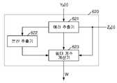
도 4는 본 발명의 데이터의 고속 전송을 위한 적응 알고리즘을 적용한 등화기의 어댑터의 기능 블록을 도시한 기능 블록도이다.4 is a functional block diagram illustrating a functional block of an adapter of an equalizer to which an adaptive algorithm for high speed data transmission of the present invention is applied.
도 4를 참조하면, 본 발명의 어댑터부(620)는 에러 추출기(621), 분산 추출기(622) 및 필터 계수 계산기(623)을 포함하여 구성될 수 있다.Referring to FIG. 4, the
본 발명의 어댑터부(620)의 동작을 설명하기에 앞서, 본 발명의 어댑터에 적용된 부호 귀환 LMS 알고리즘에 대해서 살펴본다.Prior to describing the operation of the
기존의 LMS알고리즘은 수학식 1과 같다.
The existing LMS algorithm is shown in Equation 1.
[수학식 1][Equation 1]

Wk+1은 현재 사용될 필터 계수값이고,Wk는 이전에 사용된 필터 계수값이다.μ는 이득 상수(gain constant)로서, 채널 상태에 따라 사전에 설정된다.ek는 추정된 에러값이다. 또한, Xk는 입력 신호 값이다.Wk+1 is the filter coefficient value currently to be used,and Wk is the filter coefficient value previously used.μ is a gain constant, which is set in advance according to the channel state.ek is the estimated error value. Xk is an input signal value.
상기와 같이, 기존의 LMS알고리즘은 상기ek를 최소화하여 SNR(signal to Noise Ratio)를 향상시킨다.As described above, the existing LMS algorithm minimizes theek to improve the signal to noise ratio (SNR).
다만, 기존의 LMS 알고리즘은 입력 데이터인 Xk값을 그대로 사용하기 때문에 채널 상황이나 입력 데이터의 크기에 따라 수렴의 속도가 느려질 수 있다. 이를 해결하기 위해서 본 발명에서는 Xk의 부호값을 이용하여 필터 계수를 구하는 부호 귀환 LMS 알고리즘을 제안한다.However, since the existing LMS algorithm uses the input data Xk as it is, the convergence speed may be slowed down depending on the channel condition or the size of the input data. In order to solve this problem, the present invention proposes a code feedback LMS algorithm that obtains a filter coefficient using a code value of Xk .
부호 귀환 LMS 알고리즘에서 필터 계수는 수학식 2를 이용하여 계산한다.
In the code feedback LMS algorithm, the filter coefficient is calculated using Equation 2.
[수학식 2]&Quot; (2) "

또한, 이때의 추정된 에러값은 수학식 3을 이용하여 계산한다.
In addition, the estimated error value at this time is calculated using Equation 3.
[수학식 3]&Quot; (3) "

수학식 3을 참조하면, 에러값은 Xk의 부호값인 1 또는 -1에서 입력 데이터인 Xk를 차감하여 구하는데, 일반적으로 수신 신호의 레벨이 낮기 때문에 Xk의 값도 작으므로 에러값ek은 커지게 된다.Referring to Equation 3, the error value will be subtracted for obtaining the input data Xk in the 1 or -1 sign value of Xk, generally a low level of the received signal value of the Xk is also small because the error valueek becomes large.
따라서, 기존의 LMS 알고리즘에 비해서 현재 입력되는 신호에 의한 영향을 보다 적극적으로 반영할 수 있으며, 초기 동작 시 빠른 수렴 속도를 가질 수 있다.Therefore, compared to the existing LMS algorithm, the influence of the current input signal can be more actively reflected, and it can have a faster convergence speed during the initial operation.
다만, 에러값이 수렴하지 못하고 발산하게 될 우려가 발생한다. 또한 본 발명과 같이 피드백 필터만을 사용하여 등화기를 구현한 경우에는 에러값이 발산하게 될 가능성이 더욱 높다.However, there is a fear that the error value will diverge without convergence. In addition, when the equalizer is implemented using only a feedback filter as in the present invention, an error value is more likely to be emitted.
본 발명의 등화기는 에러값이 발산하는 것을 방지하기 위해서 에러의 절대값을 통계적으로 분석하여 필터 계수를 필요에 따라 고정한다. 보다 자세히는 에러의 절대값의 분산(variance)를 구하여 분산을 최소로 하는 점에서 구한 필터 계수를 유지한다.In order to prevent the error value from diverging, the equalizer of the present invention statistically analyzes the absolute value of the error and fixes the filter coefficient as necessary. More specifically, we maintain the filter coefficients obtained by minimizing the variance by finding the variance of the absolute value of the error.
본 발명의 에러의 절대값을 구하는 과정은 수학식 4 및 수학식 5와 같다.
The process of obtaining the absolute value of the error of the present invention is shown in Equations 4 and 5.
[수학식 4]&Quot; (4) "

[수학식 5]&Quot; (5) "

Ve는 에러의 분산값으로서, 이전 주기 및 현재 주기의Ve를 비교하여 필터 계수를 유지 또는 업데이트 여부를 결정할 수 있다. 즉, 이전 주기의Ve가 현재 주기의Ve보다 큰 경우에는 에러의 분산이 감소한 것이므로 현재 주기에서 필터 계수를 계산하여 업데이트하고, 그렇지 않은 경우에는 에러의 분산이 증가한 것이므로 이전 주기의 필터 계수를 유지한다.
Ve is a variance value of the error, and may compareVe of the previous period and the current period to determine whether to maintain or update the filter coefficients. That is, in the case when the preceding periodVe is greater thanVe of the current period is because decrease the variance of the error and updating by calculating the filter coefficients in the current period, if not, because it increased the variance of the error filter coefficients of the previous cycle Keep it.
상기에서 설명한 부호 귀환 알고리즘을 구현하기 위해서, 본 발명의 에러 추출기(621)는 차감 신호YA(t) 및 등화 신호ZA(t)를 입력받아 상기 신호의 차이값을 추출한다. 슬라이싱부(520)의 동작 특성상 차감 신호의 부호값을 얻을 수 있기 때문에 결국 상기의 차이값은 수학식 3에서 제안하는 에러값이 된다.In order to implement the code feedback algorithm described above, the
분산 추출기(622)는 에러 추출기(621)에서 추출한 에러값을 통계 처리하여 에러의 절대값의 분산값을 구한다. 분산 추출기(622)는 채널의 상황에 따라서 사용 여부를 변경할 수 있다. 즉, 채널 환경이 나빠 에러값의 수렴이 어려운 경우에는 분산 추출기(622)를 동작시켜 필터 계수 값을 업데이트 또는 유지를 판단할 수 있게 한다.The
필터 계수 계산기(623)는 등화 신호ZA(t) 및 에러 추출기(621)에서 추출한 에러값을 이용하여 수학식 2에 따라 필터 계수를 계산할 수 있다. 계산된 필터 계수(W)는 필터부(610)로 전달된다.The
또한, 분산 추출기(622)에서 에러 절대값의 분산값을 입력받은 경우에는 이전 주기 및 현재 주기의 분산값을 비교하여 분산값이 감소한 경우에만 필터 계수를 계산할 수 있다. 분산값이 증가한 경우에는 분산값이 최소가 되는 점이 아니므로 필터 계수를 업데이트하지 않으므로 필터 계수를 계산할 필요가 없기 때문이다.In addition, when the
본 발명의 부호 귀환 LMS 알고리즘을 적용한 등화기를 사용함으로써, 기존의 LMS 알고리즘을 적용한 등화기에 비해서 채널 상황에 보다 유동적이고 빠르게 대응할 수 있으며, 안정적인 동작이 보장될 수 있다.
By using the equalizer to which the code-feedback LMS algorithm of the present invention is applied, it is possible to respond to the channel situation more fluidly and quickly than the equalizer to which the existing LMS algorithm is applied, and to ensure stable operation.
본 발명의 등화기를 이용한 전송 시스템의 일 실시예를 살펴본다.An embodiment of a transmission system using an equalizer of the present invention will be described.
2-PAM 신호가 백플레인 채널을 통과하는 경우에는 굉장히 열악한 채널 환경을 거치게 되며, 채널의 ISI로 인하여 수신 신호의 아이(eye)가 닫히게 된다.When the 2-PAM signal passes through the backplane channel, it undergoes a very poor channel environment, and the eye of the received signal is closed due to the ISI of the channel.
이를 방지하기 위해서, 전송 전치 등화기에서는 사전에 전송값을 선왜곡시켜 전송함으로써, 수신단에서 상대적으로 적은 ISI를 갖는 신호를 획득하게 할 수 있다.In order to prevent this, in the transmission pre-equalizer, the transmission value is predistorted and transmitted in advance, so that a receiver having a relatively small ISI can be obtained.
송신단에서는 5탭의 전송 전치 등화기를 통하여 채널을 선보상하여 채널을 통해서 송신한다. 수신단에서 본 발명의 부호 귀환 LMS 알고리즘을 적용한 5탭의 등화기를 이용하여 수신 신호를 등화하여 상대적으로 열린 아이(eye)를 가진 신호를 획득할 수 있다.
The transmitting end introduces a channel through a transmission tap equalizer of 5 taps and transmits it through the channel. The receiver may equalize the received signal using a 5-tap equalizer to which the code feedback LMS algorithm of the present invention is applied to obtain a signal having a relatively open eye.
도 6은 본 발명의 데이터의 고속 전송을 위한 적응 알고리즘을 적용한 등화 방법의 동작 흐름을 도시한 흐름도이다.6 is a flowchart illustrating an operation flow of an equalization method to which an adaptive algorithm for high speed data transmission according to the present invention is applied.
본 발명의 등화 방법은 차감 신호 생성(S10), 타이밍 신호 생성(S20), 등화 신호 생성(S30), 필터 계수 업데이트 단계(S40) 및 궤환 신호 생성(S50)의 단계를 포함하여 구성될 수 있다.The equalization method of the present invention may include a subtraction signal generation S10, a timing signal generation S20, an equalization signal generation S30, a filter coefficient updating step S40, and a feedback signal generation S50. .
차감 신호 생성 단계(S10)에서는 아날로그 입력 신호에서 아날로그 궤환 신호를 차감하여 아날로그 차감 신호를 생성할 수 있다. 차감 신호 생성 단계(S10)에서 생성된 차감 신호는 등화 신호 생성 단계(S30)에서 사용될 수 있고, 타이밍 신호 생성 단계(S20)에서도 사용될 수 있다. 차감 신호 생성 단계(S10)에서는 입력 신호에서 궤환 신호를 차감함으로써 입력 신호에 포함되어 있는 포스트-커서 ISI를 제거할 수 있다.In the subtraction signal generation step S10, an analog subtraction signal may be generated by subtracting the analog feedback signal from the analog input signal. The subtraction signal generated in the subtraction signal generation step S10 may be used in the equalization signal generation step S30, and may also be used in the timing signal generation step S20. In the subtraction signal generation step S10, the post-cursor ISI included in the input signal may be removed by subtracting the feedback signal from the input signal.
타이밍 신호 생성 단계(S20)에서는 등화 신호 단계(S30)에서 차감 신호를 샘플링하는데 필요한 샘플링 타이밍 신호를 생성할 수 있다. 샘플링 타이밍 신호는 입력 신호, 차감 신호 또는 등화 신호를 이용하여 생성할 수 있다.In the timing signal generation step S20, a sampling timing signal required to sample the subtraction signal in the equalization signal step S30 may be generated. The sampling timing signal may be generated using an input signal, a subtraction signal, or an equalization signal.
등화 신호 생성 단계(S30)에서는 상기 샘플링 타이밍 신호에 따라서 상기 차감 신호를 샘플링한 후 아날로그 신호로 변환하여 아날로그 등화 신호를 생성할 수 있다. 또한 아날로그 등화 신호에 딜레이를 가하여 샘플링 타이밍을 보정하는 과정을 더 포함할 수 있다.In the equalizing signal generation step S30, the subtraction signal may be sampled according to the sampling timing signal, and then converted into an analog signal to generate an analog equalizing signal. The method may further include correcting the sampling timing by applying a delay to the analog equalization signal.
필터 계수 업데이트 단계(S40)에서는 차감신호 및 등화 신호에 부호 귀환 LMS 알고리즘을 적용하여 필터 계수값을 계산하고 업데이트할 수 있다.In the filter coefficient updating step (S40), the filter coefficient value may be calculated and updated by applying a code feedback LMS algorithm to the subtraction signal and the equalization signal.
슬라이싱 장치의 동작 특성상 등화 신호는 차감 신호를 sign함수에 대입하여 얻은 결과 값과 같기 때문에 차감 신호 및 등화 신호를 사용함으로써 별도의 sign함수 장치를 사용하지 않고도 부호 귀환 LMS 알고리즘을 수행할 수 있다.Because the equalization signal is the same as the result obtained by substituting the subtraction signal into the sign function, the sign feedback LMS algorithm can be performed by using the subtraction signal and the equalization signal without using a separate sign function device.
부호 귀환 LMS 알고리즘 수행과 관련된 사항은 아래에 기술한다.The matters related to performing the code feedback LMS algorithm are described below.
궤환 신호 생성 단계(S50)에서는 필터 계수값과 등화 신호를 이용하여 아날로그 궤환 신호를 생성한다. 이를 위해서, 디지털 필터와 ZOH를 사용할 수 있다.In the feedback signal generation step S50, an analog feedback signal is generated using the filter coefficient value and the equalization signal. To this end, digital filters and ZOH can be used.
도시하지는 않았으나 필요에 따라서는, 등화 신호 생성 단계(S30)에서 생성된 등화 신호를 출력하는 출력 단계가 추가될 수 있다. 출력 단계는 필터 계수 업데이트 단계(S40) 및 궤환 신호 생성 단계(S50)와 병렬적으로 수행될 수 있다.
Although not shown, if necessary, an output step of outputting the equalization signal generated in the equalization signal generation step S30 may be added. The output step may be performed in parallel with the filter coefficient update step S40 and the feedback signal generation step S50.
도 7은 본 발명의 데이터의 고속 전송을 위한 적응 알고리즘을 적용한 등화 방법의 필터 계수 업데이트 단계에서의 상세 흐름도를 도시한 흐름도이다.7 is a flowchart illustrating a detailed flowchart in the filter coefficient updating step of the equalization method to which the adaptive algorithm for high speed data transmission according to the present invention is applied.
도 7을 참조하면, 본 발명의 필터 계수 업데이트 단계(S40)는 에러 추출 과정(S41), 필터 계수 계산 과정(S44) 및 업데이트 과정(S45)을 포함할 수 있고, 에러 분산 계산 과정(S42) 및 분산 감소 판단 과정(S43)이 더 포함될 수 있다.Referring to FIG. 7, the filter coefficient updating step S40 of the present invention may include an error extraction process S41, a filter coefficient calculation process S44, and an update process S45, and an error variance calculation process S42. And a decrease reduction process (S43).
필터 계수 업데이트 단계에서는 상기에서 설명한 부호 귀환 LMS 알고리즘을 수행하여 필터 계수를 업데이트한다.In the filter coefficient updating step, the filter coefficients are updated by performing the code feedback LMS algorithm described above.
에러 추출 과정(S41)에서는 수학식 3에 따라 차감 신호 및 등화 신호를 이용하여 에러를 추출한다. 추출된 에러는 필터 계수 계산 과정(S44)에서 사용될 수 있고, 에러 분산 계산 과정(S42)에서도 사용될 수 있다.In the error extraction process (S41), an error is extracted using a subtraction signal and an equalization signal according to Equation (3). The extracted error may be used in the filter coefficient calculation process S44 and may also be used in the error variance calculation process S42.
필터 계수 계산 과정(S44)에서는 수학식 2에 따라 현재 주기의 필터 계수를 계산한다. 수학식 2에 따라 필터 계수를 계산함으로 채널의 변화에 보다 빠르게 적응하여 필터 계수를 빠르게 수렴시킬 수 있다.In the filter coefficient calculation process (S44), the filter coefficient of the current period is calculated according to Equation 2. By calculating the filter coefficients according to Equation 2, the filter coefficients can be quickly converged by adapting to the change of the channel faster.
업데이트 과정(S45)에서는 필터 계수 계산 과정(S44)에서 계산된 필터 계수를 궤환 신호 생성 단계(S50)로 전달한다.In the update process S45, the filter coefficients calculated in the filter coefficient calculation process S44 are transferred to the feedback signal generation step S50.
채널 환경에 따라서 필터 계수 계산 과정(S44)에서 계산되는 필터 계수가 수렴하지 않을 수 있다. 이를 방지하기 위해서 에러 분산 계산 과정(S42) 및 분산 감소 판단 과정(S43)이 추가하여 분산이 최소가 되는 점의 필터 계수로 고정시킬 수 있다.Depending on the channel environment, the filter coefficients calculated in the filter coefficient calculation process S44 may not converge. In order to prevent this, an error variance calculation process S42 and a dispersion decrease determination process S43 may be added to fix the filter coefficient at the point where the variance becomes the minimum.
에러 분산 계산 과정(S42)에서는 에러 추출 과정(S41)에서 계산한 에러들의 통계적 분산(variance)를 계산한다.In the error variance calculation process S42, a statistical variance of the errors calculated in the error extraction process S41 is calculated.
분산 감소 판단 과정(S43)에서는 에러 분산 계산 과정(S42)에서 계산한 에러의 분산이 감소한 경우에만 필터 계수 계산 과정 및 업데이트 과정이 수행되도록 한다. 에러의 분산이 증가한 경우에는 필터 계수의 계산 및 업데이트를 수행하지 않아 이전 주기의 필터 계수가 유지되도록 한다. 상기와 같은 과정을 통해서, 분산이 최소가 되는 점에서의 필터 계수가 유지되어 필터 계수가 발산하는 것을 방지할 수 있다.In the variance reduction determination process S43, the filter coefficient calculation process and the update process may be performed only when the variance of the error calculated in the error variance calculation process S42 is reduced. When the variance of the error increases, the filter coefficients of the previous period are maintained by not calculating and updating the filter coefficients. Through the above process, it is possible to prevent the filter coefficients from diverging by maintaining the filter coefficients at the point where dispersion is minimized.
본 발명의 필터 계수 업데이트 단계는 종래의 LMS 알고리즘을 적용한 필터 계수 계산 방식들보다 환경에 보다 빠르게 적응할 수 있으며, 안정적인 동작을 보장할 수 있다.
The filter coefficient updating step of the present invention can adapt to the environment faster than the filter coefficient calculation schemes using the conventional LMS algorithm, and can ensure stable operation.
이상에서 설명한 본 발명은 전술한 실시 예 및 첨부된 도면에 의해 한정되는 것이 아니고, 본 발명의 기술적 사상을 벗어나지 않는 범위 내에서 여러 가지 치환, 변형 및 변경할 수 있다는 것은 본 발명이 속하는 기술 분야에서 통상의 지식을 가진 당업자에게 있어 명백할 것이다.
It will be apparent to those skilled in the art that various modifications and variations can be made in the present invention without departing from the spirit or scope of the inventions. To those skilled in the art.
200: 종래의 결정 궤환 등화기
210: 샘플링 타이밍 추출부220: 샘플러
230: 피드 포워드 필터240: 차감기
250; 슬라이서260: 피드백 필터
270: 어댑터
300: 차감장치400: 타이밍 신호 생성 장치
500: 등화 신호 생성 장치600: 궤환 신호 생성 장치
510: 샘플러부520; 슬라이싱부530; 딜레이 버퍼부
610: 필터부620: 어댑터부630: 변환부
621: 에러 추출기622: 분산 추출기623: 필터 계수 계산기
611: 지연탭 612: 곱셈기
XA(t): 입력 신호YA(t): 차감 신호 ZA(t): 등화 신호
FA(t): 궤환 신호
S10: 차감 신호 생성 단계S20: 타이밍 신호 생성 단계
S30: 등화 신호 생성 단계S40: 필터 계수 업데이트 단계
S50: 궤환 신호 생성 단계
S41: 에러 추출 과정S42: 에러 분산 계산 과정
S43: 분산 감소 판단 과정S44: 필터 계수 계산
S45: 업데이트 과정200: conventional crystal feedback equalizer
210: sampling timing extraction unit 220: sampler
230: feed forward filter 240: subtraction
250; Slicer 260: Feedback Filter
270: adapter
300: subtraction device 400: timing signal generator
500: equalization signal generator 600: feedback signal generator
510:
610: filter unit 620: adapter unit 630: conversion unit
621: error extractor 622: variance extractor 623: filter coefficient calculator
611: delay tap 612: multiplier
XA (t): Input signal YA (t): Subtraction signal ZA (t): Equalization signal
FA (t): feedback signal
S10: subtraction signal generation step S20: timing signal generation step
S30: equalization signal generation step S40: filter coefficient updating step
S50: Feedback signal generation step
S41: Error Extraction Process S42: Error Variance Calculation Process
S43: variance reduction judgment process S44: filter coefficient calculation
S45: update process
Claims (15)
Translated fromKorean샘플링 타이밍 신호를 생성하는 타이밍 신호 생성 장치;
상기 차감 신호를 상기 타이밍 신호에 따라 등화시켜 등화 신호를 생성하는 등화 신호 생성 장치; 및
상기 차감 신호 및 등화 신호를 이용하여 필터 계수값을 계산한 후 상기 등화 신호를 지연시키고 상기 필터 계수값에 따라 상기 지연된 등화 신호를 가중 처리하여 궤환신호를 생성하는 궤환 신호 생성 장치를 포함하고,
상기 궤환 신호 생성 장치는
상기 차감신호 및 등화 신호를 이용하여 부호 귀환 LMS 알고리즘을 적용하여 상기 필터 계수 값을 구하는 어댑터부; 및
상기 등화 신호를 순차적으로 지연시키고 상기 각각 지연된 등화 신호를 상기 필터 계수값을 이용하여 가중 처리하는 필터부
를 포함하는 것을 특징으로 하는 등화기.
A subtraction device for generating a subtraction signal by subtracting the feedback signal from the input signal;
A timing signal generation device for generating a sampling timing signal;
An equalization signal generation device for generating an equalization signal by equalizing the subtraction signal according to the timing signal; And
A feedback signal generator for calculating a filter coefficient value using the subtraction signal and the equalization signal, delaying the equalization signal, and weighting the delayed equalization signal according to the filter coefficient value to generate a feedback signal;
The feedback signal generating device
An adapter unit applying the code feedback LMS algorithm using the subtraction signal and the equalization signal to obtain the filter coefficient value; And
A filter unit for sequentially delaying the equalization signals and weighting each delayed equalization signal using the filter coefficient values
Equalizer comprising a.
상기 등화 신호의 부하값 및 등화 신호값을 이용하여 에러값을 추출하는 에러 추출기; 및
상기 에러값 및 등화신호를 이용하여 필터 계수값을 계산하는 탭계수 계산기를 포함하는 등화기.
The method of claim 1, wherein the adapter unit
An error extractor for extracting an error value using the load value of the equalized signal and the equalized signal value; And
And a tap coefficient calculator for calculating a filter coefficient value using the error value and the equalization signal.
전 주기에서 계산된 상기 분산값과 현재 주기에서 계산된 상기 분산값을 비교하여 현재 주기의 분산값이 감소된 경우에는 필터 계수값을 계산하여 상기 필터부에 업데이트하며,
전 주기에서 계산된 상기 분산값과 현재 주기에서 계산된 상기 분산값을 비교하여 현재 주기의 분산값이 증가 또는 유지된 경우에는 전 주기의 필터 계수값을 유지하는 것을 특징으로 하는 등화기.
The tap coefficient calculator of claim 3, wherein the adapter unit further comprises a dispersion calculator for calculating a statistical dispersion of the error value.
If the dispersion value of the current period is reduced by comparing the dispersion value calculated in the previous period with the dispersion value calculated in the current period, the filter coefficient value is calculated and updated in the filter unit.
And comparing the variance value calculated in the previous period with the variance value calculated in the current period to maintain the filter coefficient value of the previous period when the variance value of the current period is increased or maintained.
5. The equalizer of claim 4, wherein the variance value calculated by the variance calculator is a variance value of the square of the error value extracted by the error extractor.
상기 필터부의 출력 신호를 아날로그화하는 신호 변환부를 더 포함하는 것을 특징으로 하는 등화기.
The apparatus of claim 1, wherein the feedback signal generator
And a signal converter configured to analogize the output signal of the filter unit.
상기 필터부의 출력 신호를 아날로그 신호로 변환하는 제로 오더 홀드(ZOH, zero order hold); 및
상기 제로 오더 홀드에서 변환된 신호를 저대역 필터링하는 저대역 통과 필터를 포함하는 것을 특징으로 하는 등화기.
The method of claim 6, wherein the signal conversion unit
A zero order hold (ZOH) for converting the output signal of the filter unit into an analog signal; And
And a low pass filter for low band filtering the signal converted at the zero order hold.
상기 차감 신호를 상기 타이밍 신호에 따라 샘플링하여 샘플링 신호를 출력하는 샘플링부; 및
상기 샘플링 신호를 슬라이싱하여 등화 신호를 생성하는 슬라이싱부를 포함하는 것을 특징으로 하는 등화기.
The apparatus of claim 1, wherein the equalization signal generator
A sampling unit sampling the subtraction signal according to the timing signal to output a sampling signal; And
And a slicing unit for slicing the sampling signal to generate an equalization signal.
10. The equalizer of claim 8, wherein the equalization signal generation device further comprises a delay buffer unit for delaying and outputting the equalization signal.
The equalizer of claim 1, wherein the equalizer is implemented in a serializer / deserializer.
샘플링 타이밍 신호를 이용하여 상기 차감 신호로부터 등화 신호를 생성하는 등화 단계;
상기 차감신호 및 등화 신호를 이용하여 필터 계수값을 계산하고 업데이트 하는 필터 계수 업데이트 단계; 및
상기 등화 신호를 지연시키고 상기 계산된 필터 계수값에 따라 상기 지연된 등화 신호를 가중 처리하여 궤환신호를 생성하는 궤환 신호 생성 단계를 포함하고,
상기 필터 계수 업데이트 단계는
상기 차감 신호 및 상기 등화 신호의 차이값인 에러값를 추출하는 에러값 추출 과정; 및
상기 에러값 및 상기 에러값의 부호값을 이용하여 부호 귀환 LMS 알고리즘에 따라 탭계수를 계산하는 탭계수 계산 과정
을 포함하는 것을 특징으로 하는 등화 방법.
A subtraction signal generation step of generating a subtraction signal by subtracting a feedback signal obtained from a signal one cycle before from an input signal;
An equalization step of generating an equalization signal from the subtraction signal using a sampling timing signal;
A filter coefficient updating step of calculating and updating a filter coefficient value using the subtraction signal and the equalization signal; And
A feedback signal generation step of delaying the equalization signal and weighting the delayed equalization signal according to the calculated filter coefficient value to generate a feedback signal;
The filter coefficient updating step
An error value extraction step of extracting an error value that is a difference value between the subtraction signal and the equalization signal; And
Tap coefficient calculation process using the error value and the code value of the error value to calculate the tap coefficient according to the code feedback LMS algorithm
Equalization method comprising a.
상기 차감 신호 및 상기 등화 신호의 차이값인 에러값를 추출하는 에러값 추출 과정;
상기 에러 신호의 통계적 분산값을 계산하는 분산값 계산 과정; 및
전 주기의 상기 계산된 분산값과 현재주기의 상기 계산된 분산값의 크기를 비교하는 분산값 비교 과정; 및
상기 에러값 및 상기 에러값의 부호값을 이용하여 부호 귀환 LMS 알고리즘에 따라 탭계수를 계산하는 탭계수 계산 과정을 포함하며,
상기 분산값 비교 과정에서 현재 주기의 분산값이 전 주기의 계산된 분산값에 비해 감소된 경우에는 상기 탭계수 계산 과정을 수행하며,
상기 분산값 비교 과정에서 현재 주기의 분산값이 전 주기의 분산값에 비해 증가 또는 유지된 경우에는 상기 전 주기의 필터 계수값을 유지하는 것을 특징으로 하는 등화 방법.
The method of claim 11, wherein the filter coefficient updating step
An error value extraction step of extracting an error value that is a difference value between the subtraction signal and the equalization signal;
A dispersion value calculation step of calculating a statistical dispersion value of the error signal; And
A variance value comparison process of comparing a magnitude of the calculated variance value of the previous period with the calculated variance value of the current period; And
A tap coefficient calculation process of calculating a tap coefficient according to a code feedback LMS algorithm using the error value and the sign value of the error value,
When the dispersion value of the current period is decreased in comparison with the calculated dispersion value of the previous period in the comparison of the dispersion value, the tap coefficient calculation process is performed.
The filter coefficient value of the previous period is maintained when the dispersion value of the current period is increased or maintained in comparison with the dispersion value of the previous period in the comparison of the dispersion values.
The equalization method of claim 13, wherein the variance value is a variance value of the square of the error value extracted in the error value extraction process.
Priority Applications (2)
| Application Number | Priority Date | Filing Date | Title |
|---|---|---|---|
| KR1020100062334AKR101363122B1 (en) | 2010-06-29 | 2010-06-29 | Apparatus and Method of equalizing applied adaptation algorithm for high speed transmission |
| US12/881,586US8446941B2 (en) | 2010-06-29 | 2010-09-14 | Equalizer employing adaptive algorithm for high speed data transmissions and equalization method thereof |
Applications Claiming Priority (1)
| Application Number | Priority Date | Filing Date | Title |
|---|---|---|---|
| KR1020100062334AKR101363122B1 (en) | 2010-06-29 | 2010-06-29 | Apparatus and Method of equalizing applied adaptation algorithm for high speed transmission |
Publications (2)
| Publication Number | Publication Date |
|---|---|
| KR20120001512A KR20120001512A (en) | 2012-01-04 |
| KR101363122B1true KR101363122B1 (en) | 2014-02-13 |
Family
ID=45352539
Family Applications (1)
| Application Number | Title | Priority Date | Filing Date |
|---|---|---|---|
| KR1020100062334AExpired - Fee RelatedKR101363122B1 (en) | 2010-06-29 | 2010-06-29 | Apparatus and Method of equalizing applied adaptation algorithm for high speed transmission |
Country Status (2)
| Country | Link |
|---|---|
| US (1) | US8446941B2 (en) |
| KR (1) | KR101363122B1 (en) |
Families Citing this family (7)
| Publication number | Priority date | Publication date | Assignee | Title |
|---|---|---|---|---|
| US8831142B2 (en)* | 2012-12-18 | 2014-09-09 | Lsi Corporation | Adaptive cancellation of voltage offset in a communication system |
| KR101759955B1 (en)* | 2013-11-01 | 2017-07-21 | 엘지전자 주식회사 | Method and apparatus for receiving signal in wireless communication system |
| WO2016101255A1 (en)* | 2014-12-26 | 2016-06-30 | 华为技术有限公司 | Signal compensation method and device |
| US10686630B1 (en)* | 2019-07-15 | 2020-06-16 | Mellanox Technologies, Ltd. | Method and apparatus for blind channel estimation |
| US11171815B2 (en)* | 2020-01-21 | 2021-11-09 | Credo Technology Group Limited | Digital equalizer with overlappable filter taps |
| CN112787963B (en)* | 2020-12-25 | 2022-09-20 | 中国科学院微电子研究所 | Signal processing method, device and system for adaptive decision feedback equalization |
| CN112803920B (en)* | 2020-12-30 | 2023-02-03 | 重庆邮电大学 | Sparse system identification method and filter and system based on improved LMS algorithm |
Citations (2)
| Publication number | Priority date | Publication date | Assignee | Title |
|---|---|---|---|---|
| US20040146129A1 (en)* | 2003-01-24 | 2004-07-29 | Chan-Shih Lin | Decision sequence generating method and associated receiver with a decision feedback equalizer |
| US20100080282A1 (en)* | 2008-09-29 | 2010-04-01 | Zhong Freeman Y | Re-adaption of equalizer parameter to center a sample point in a baud-rate clock and data recovery receiver |
Family Cites Families (13)
| Publication number | Priority date | Publication date | Assignee | Title |
|---|---|---|---|---|
| US7012957B2 (en)* | 2001-02-01 | 2006-03-14 | Broadcom Corporation | High performance equalizer having reduced complexity |
| US7151796B2 (en)* | 2001-02-01 | 2006-12-19 | Broadcom Corporation | High performance equalizer with enhanced DFE having reduced complexity |
| US7027503B2 (en)* | 2002-06-04 | 2006-04-11 | Qualcomm Incorporated | Receiver with a decision feedback equalizer and a linear equalizer |
| US7266146B2 (en)* | 2002-06-18 | 2007-09-04 | Ralink Technology, Inc. | Symbol-based decision feedback equalizer (DFE) optimal equalization method and apparatus with maximum likelihood sequence estimation for wireless receivers under multipath channels |
| US7242712B1 (en)* | 2004-03-08 | 2007-07-10 | Pmc-Sierra, Inc. | Decision feedback equalizer (DFE) for jitter reduction |
| US7340000B1 (en)* | 2004-08-13 | 2008-03-04 | Cisco Technology, Inc. | Decision feedback equalizer in an OFDM WLAN receiver |
| US7447262B2 (en)* | 2005-05-12 | 2008-11-04 | Rdc Semiconductor Co., Ltd. | Adaptive blind start-up receiver architecture with fractional baud rate sampling for full-duplex multi-level PAM systems |
| WO2007095112A2 (en)* | 2006-02-14 | 2007-08-23 | Baker Hughes Incorporated | Decision feedback equalization in mud-pulse telemetry |
| US20080056403A1 (en)* | 2006-09-01 | 2008-03-06 | On Demand Microelectronics | Method and apparatus for timing recovery of pam signals |
| US7561864B2 (en)* | 2006-12-03 | 2009-07-14 | General Dynamics C4 Systems, Inc. | RF receiver with NLMS channel estimator and method therefor |
| US8170128B2 (en)* | 2007-09-05 | 2012-05-01 | Iberium Communications, Inc. | Method and apparatus for joint decoding and equalization |
| US8467440B2 (en)* | 2010-05-10 | 2013-06-18 | Lsi Corporation | Compensated phase detector for generating one or more clock signals using DFE detected data in a receiver |
| US8787776B2 (en)* | 2010-06-04 | 2014-07-22 | The Governing Council Of The University Of Toronto | Optical receiver with monolithically integrated photodetector |
- 2010
- 2010-06-29KRKR1020100062334Apatent/KR101363122B1/ennot_activeExpired - Fee Related
- 2010-09-14USUS12/881,586patent/US8446941B2/ennot_activeExpired - Fee Related
Patent Citations (2)
| Publication number | Priority date | Publication date | Assignee | Title |
|---|---|---|---|---|
| US20040146129A1 (en)* | 2003-01-24 | 2004-07-29 | Chan-Shih Lin | Decision sequence generating method and associated receiver with a decision feedback equalizer |
| US20100080282A1 (en)* | 2008-09-29 | 2010-04-01 | Zhong Freeman Y | Re-adaption of equalizer parameter to center a sample point in a baud-rate clock and data recovery receiver |
Also Published As
| Publication number | Publication date |
|---|---|
| US20110317754A1 (en) | 2011-12-29 |
| KR20120001512A (en) | 2012-01-04 |
| US8446941B2 (en) | 2013-05-21 |
Similar Documents
| Publication | Publication Date | Title |
|---|---|---|
| KR101363122B1 (en) | Apparatus and Method of equalizing applied adaptation algorithm for high speed transmission | |
| US8831142B2 (en) | Adaptive cancellation of voltage offset in a communication system | |
| US20150381393A1 (en) | Adaptive Cancellation of Voltage Offset in a Communication System | |
| US7764732B2 (en) | Adaptive error slicer and residual intersymbol interference estimator | |
| CN105791188B (en) | PAM data communication system with reflection cancellation | |
| US8027409B2 (en) | Noise prediction-based signal detection and cross-talk mitigation | |
| US7023912B2 (en) | Hybrid adaptive equalizer for optical communications systems | |
| US8208529B2 (en) | Equalization apparatus and method of compensating distorted signal and data receiving apparatus | |
| US8582635B2 (en) | Sparse and reconfigurable floating tap feed forward equalization | |
| US8467440B2 (en) | Compensated phase detector for generating one or more clock signals using DFE detected data in a receiver | |
| US20130243066A1 (en) | Decision feedforward equalization | |
| EP2613452A1 (en) | Digital filter device, digital filtering method, and control program for digital filter device | |
| CN113572489B (en) | Timing recovery device, jitter mitigation circuit and receiver device | |
| CN111869157B (en) | Timing recovery apparatus and timing recovery method for use in data transmission system | |
| US10938604B2 (en) | Receiver supporting multiple data rates with fast equalization | |
| US6996230B1 (en) | Echo-canceler for precoded fractionally spaced receiver using signal estimator | |
| KR101359691B1 (en) | Apparatus and Method of equalizing for high speed transmission | |
| KR100848127B1 (en) | Apparatus and Method for Stable DFE using selective FBF | |
| CN114208065B (en) | Noise cancellation apparatus and method for receiver | |
| US12401346B2 (en) | Efficient architecture for high-performance DSP-based long-reach SERDES | |
| Cohen et al. | Robust dithering based stabilization for quantized LMS adaptation | |
| WO2017037836A1 (en) | Signal transmission apparatus and signal transmission system | |
| Neurohr et al. | Adaptive decision-feedback equalization for band-limited high-speed serial links | |
| Pessoa et al. | Assessment of parallel equalizer/phase estimation algorithms in coherent optical systems |
Legal Events
| Date | Code | Title | Description |
|---|---|---|---|
| A201 | Request for examination | ||
| PA0109 | Patent application | St.27 status event code:A-0-1-A10-A12-nap-PA0109 | |
| PA0201 | Request for examination | St.27 status event code:A-1-2-D10-D11-exm-PA0201 | |
| PG1501 | Laying open of application | St.27 status event code:A-1-1-Q10-Q12-nap-PG1501 | |
| R17-X000 | Change to representative recorded | St.27 status event code:A-3-3-R10-R17-oth-X000 | |
| E902 | Notification of reason for refusal | ||
| PE0902 | Notice of grounds for rejection | St.27 status event code:A-1-2-D10-D21-exm-PE0902 | |
| E13-X000 | Pre-grant limitation requested | St.27 status event code:A-2-3-E10-E13-lim-X000 | |
| P11-X000 | Amendment of application requested | St.27 status event code:A-2-2-P10-P11-nap-X000 | |
| P13-X000 | Application amended | St.27 status event code:A-2-2-P10-P13-nap-X000 | |
| E701 | Decision to grant or registration of patent right | ||
| PE0701 | Decision of registration | St.27 status event code:A-1-2-D10-D22-exm-PE0701 | |
| GRNT | Written decision to grant | ||
| PR0701 | Registration of establishment | St.27 status event code:A-2-4-F10-F11-exm-PR0701 | |
| PR1002 | Payment of registration fee | St.27 status event code:A-2-2-U10-U11-oth-PR1002 Fee payment year number:1 | |
| PG1601 | Publication of registration | St.27 status event code:A-4-4-Q10-Q13-nap-PG1601 | |
| S14-X000 | Exclusive voluntary license recorded | St.27 status event code:A-4-4-S10-S14-lic-X000 | |
| PN2301 | Change of applicant | St.27 status event code:A-5-5-R10-R13-asn-PN2301 St.27 status event code:A-5-5-R10-R11-asn-PN2301 | |
| LAPS | Lapse due to unpaid annual fee | ||
| PC1903 | Unpaid annual fee | St.27 status event code:A-4-4-U10-U13-oth-PC1903 Not in force date:20170208 Payment event data comment text:Termination Category : DEFAULT_OF_REGISTRATION_FEE | |
| R18-X000 | Changes to party contact information recorded | St.27 status event code:A-5-5-R10-R18-oth-X000 | |
| PC1903 | Unpaid annual fee | St.27 status event code:N-4-6-H10-H13-oth-PC1903 Ip right cessation event data comment text:Termination Category : DEFAULT_OF_REGISTRATION_FEE Not in force date:20170208 |