KR101361096B1 - Optical system for see-through head mounted display - Google Patents
Optical system for see-through head mounted displayDownload PDFInfo
- Publication number
- KR101361096B1 KR101361096B1KR1020120142770AKR20120142770AKR101361096B1KR 101361096 B1KR101361096 B1KR 101361096B1KR 1020120142770 AKR1020120142770 AKR 1020120142770AKR 20120142770 AKR20120142770 AKR 20120142770AKR 101361096 B1KR101361096 B1KR 101361096B1
- Authority
- KR
- South Korea
- Prior art keywords
- wedge prism
- image
- optical system
- image light
- mounted display
- Prior art date
- Legal status (The legal status is an assumption and is not a legal conclusion. Google has not performed a legal analysis and makes no representation as to the accuracy of the status listed.)
- Expired - Fee Related
Links
Images


Classifications
- G—PHYSICS
- G02—OPTICS
- G02B—OPTICAL ELEMENTS, SYSTEMS OR APPARATUS
- G02B27/00—Optical systems or apparatus not provided for by any of the groups G02B1/00 - G02B26/00, G02B30/00
- G02B27/01—Head-up displays
- G02B27/017—Head mounted
- G02B27/0172—Head mounted characterised by optical features
- G—PHYSICS
- G02—OPTICS
- G02B—OPTICAL ELEMENTS, SYSTEMS OR APPARATUS
- G02B27/00—Optical systems or apparatus not provided for by any of the groups G02B1/00 - G02B26/00, G02B30/00
- G02B27/02—Viewing or reading apparatus
- G02B27/022—Viewing apparatus
- G—PHYSICS
- G02—OPTICS
- G02B—OPTICAL ELEMENTS, SYSTEMS OR APPARATUS
- G02B27/00—Optical systems or apparatus not provided for by any of the groups G02B1/00 - G02B26/00, G02B30/00
- G02B27/01—Head-up displays
- G02B27/0101—Head-up displays characterised by optical features
- G02B27/0103—Head-up displays characterised by optical features comprising holographic elements
- G02B2027/0105—Holograms with particular structures
- G—PHYSICS
- G02—OPTICS
- G02B—OPTICAL ELEMENTS, SYSTEMS OR APPARATUS
- G02B27/00—Optical systems or apparatus not provided for by any of the groups G02B1/00 - G02B26/00, G02B30/00
- G02B27/01—Head-up displays
- G02B27/0101—Head-up displays characterised by optical features
- G02B2027/0123—Head-up displays characterised by optical features comprising devices increasing the field of view
Landscapes
- Physics & Mathematics (AREA)
- General Physics & Mathematics (AREA)
- Optics & Photonics (AREA)
Abstract
Translated fromKoreanDescription
Translated fromKorean본 발명은 투과형 헤드마운트 디스플레이(HEAD MOUNTED DISPLAY, HMD) 광학시스템에 관한 것으로서, 더욱 상세하게는 외부 활동 중에도 정보 획득을 용이하게 할 수 있고, 부피와 무게를 현저히 줄일 수 있으면서도 대화면 시청이 가능하며, 제조비용을 절감하여 제품가격을 현저히 낮출 수 있는 투과형 헤드마운트 디스플레이 광학시스템에 관한 것이다.
The present invention relates to a transmissive head mounted display (HMD) optical system, and more particularly, it is possible to easily obtain information even during external activities, to significantly reduce volume and weight, and to view a large screen. The present invention relates to a transmissive head mounted display optical system that can reduce manufacturing costs and significantly lower product prices.
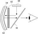
일반적으로 헤드마운트 디스플레이(HMD) 장치는 눈과 매우 근접한 위치에서 발생하는 영상광을 정밀한 광학 장치를 이용하여 먼 거리에 가상의 대형화면이 구성될 수 있도록 초점을 형성함으로써 사용자로 하여금 확대된 허상을 볼 수 있도록 하는 화상 표시 장치로서, 주위 환경은 볼 수 없고 디스플레이 소자에서 발산된 영상광만을 볼 수 있는 폐쇄형 HMD (See-close HMD) 방식과, 윈도우를 통해 주위 환경을 볼 수 있으면서도 디스플레이 소자에서 발산된 영상광 또한 볼 수 있는 투과형 HMD (See-through HMD) 방식으로 나뉜다. 도 1은 종래 기술에 따른 투과형 HMD의 광학시스템의 예를 보여주고 있다.In general, a head mounted display (HMD) device uses a precise optical device to focus a video light generated at a position very close to an eye so that a virtual large screen can be composed at a long distance, thereby allowing a user to enlarge an enlarged virtual image. An image display device for viewing, including a closed HMD (See-close HMD) method that can see only the image light emitted from the display element, not the surrounding environment, and the display element while viewing the surrounding environment through a window. The emitted image light is also divided into a see-through HMD method. 1 shows an example of an optical system of a transmissive HMD according to the prior art.
먼저, 도 1에 도시된 투과형 HMD는 국내 특허등록번호 제10-0928226호로 게시되었으며, 영상광을 발산하는 디스플레이 소자(10)와, 상기 마이크로 디스플레이 패널에서 나오는 광 중 특정 편광만을 반사시키는 편광분리기(11)와, 상기 편광분리기에서 반사된 선편광을 원편광으로 변환시키거나 입사된 원편광을 선편광으로 변화시키는 위상 지연판(12)과, 상기 위상 지연판(12)을 통과한 원편광된 광을 확대하여 다시 상기 위상 지연판(12)으로 보내주는 반투과 오목 반사경(13)과, 주변 광을 개폐할 수 있도록 상기 반투과 오목 반사경의 외측면에 부착된 광 개폐 스위치 패널(14)을 포함하는 HMD 장치의 광학시스템으로 이루어진다.First, the transmission-type HMD shown in FIG. 1 has been published in Korean Patent Registration No. 10-0928226, and has a
위와 같은 구성에 의하여, 상기 디스플레이 소자(10)에서 생성된 영상광은 상기 디스플레이 소자(10)에 45도 기울여 배치된 상기 편광분리기(11)에 의해 90도 방향으로 전체 영상광중 P파 혹은 S파 성질의 50% 빔만이 투과 또는 반사되어 상기 위상 지연판(12)에 도달하며, 상기 위상 지연판(12)에서 선편광된 영상광이 원편광으로 바뀌어 상기 반투과 오목반사경(13)에 도달한 후 반사되며 회전 방향이 반대인 원편광 상태가 되어 상기 위상지연판(12)과 상기 편광분리기(11)를 다시 통과하여 사용자의 눈에 도달함으로써 상기 반투과 오목반사경(13)에서 확대된 영상을 사용자는 시청할 수 있게 된다.By the above configuration, the image light generated by the
그러나 전술한 종래의 기술은 디스플레이 소자(10)로부터 생성된 영상광이 상기 편광분리기(11)와 상기 반투과 오목반사경(13)에 통과하며 각각 50%의 광량이 손실되어 최초 광량의 25%만이 양안으로 전달되며 75%는 반사과정에서 유실되게 되므로 원 영상광의 자연색을 구현하기가 힘들어 지게 되고, 그에 따라 사용자의 안구에 적정한 밝기의 화상을 제공하기 위해서는 유실되는 광량의 크기를 감안하여 고휘도의 광원을 별도로 사용해야 하는 문제점이 있다.However, in the above-described conventional technique, image light generated from the
또한, 상기 반투과 오목반사경(13)에서 확대된 영상이 양 안에 도달하기까지의 공간에 상기 편광분리기(11)이 대각으로 위치하고 있으므로, 통상적인 헤드마운트 디스플레이의 목적인 시야각(FOV) 또는 아이 박스(Eye Box)를 크게 하는데 구조적인 문제점을 가지고 있으며, 이들을 확대하기 위해서는 기구 전체의 크기와 무게가 늘어날 수밖에 없어 사용자가 착용하였을 경우 얼굴 전체에 압박 요인이 되어 쉽게 피로감을 느끼게 되는 문제점이 있다.
In addition, since the
따라서 위와 같은 종래의 문제점을 해결하기 위한 본 발명의 목적은 디스플레이 소자에서 발산되는 영상광의 손실을 최소화함으로써 영상광과 외부 영상광을 동시에 선명하게 시청할 수 있도록 하여 보행 중에도 이메일 및 정보 수집 등의 활동을 할 수 있어 보다 효율적인 업무추진을 할 수 있는 투과형 헤드마운트 디스플레이 광학시스템을 제공함에 있다.Accordingly, an object of the present invention for solving the above-mentioned problems is to minimize the loss of the video light emitted from the display element so that the video light and external video light can be clearly viewed simultaneously so that activities such as e-mail and information collection can be performed while walking. It is possible to provide a transmissive head-mounted display optical system that enables more efficient work promotion.
또한, 본 발명의 다른 목적은 무게와 부피를 현저히 줄일 수 있으면서도 가상화면 크기를 극대화하여 대화면 시청이 가능한 투과형 헤드마운트 디스플레이 광학시스템을 제공함에 있다.In addition, another object of the present invention is to provide a transmissive head-mounted display optical system that can greatly reduce the weight and volume while maximizing the size of the virtual screen to view the big screen.
또한, 본 발명의 또 다른 목적은 웨지프리즘 사용에 의한 확대방식을 적용하여 렌즈 가공을 최소화함으로써 제조비용을 절감할 수 있는 투과형 헤드마운트 디스플레이 광학시스템을 제공함에 있다.
In addition, another object of the present invention is to provide a transmission-type head mounted display optical system that can reduce the manufacturing cost by minimizing the lens processing by applying the expansion method by using the wedge prism.
상기의 목적을 달성하기 위한 본 발명에 따른 투과형 헤드마운트 디스플레이 광학시스템은, 디스플레이 소자; 상기 디스플레이 소자부터 발산되는 영상광을 평행하게 만들어주는 콜리메이션 렌즈; 상기 콜리메이션 렌즈를 통과하여 평행하게 정렬된 영상광이 입사되어 수평방향으로 영상을 확대할 수 있도록 제 1 확대수단을 구비하는 제 1 웨지프리즘; 상기 제 1 웨지프리즘을 통과하여 수평방향으로 확대된 영상광이 입사하여 수직방향으로 영상을 확대할 수 있도록 제 2 확대수단을 구비하는 제 2 웨지프리즘; 및 상기 제 2 웨지프리즘에서 반사되어 수직방향으로 확대된 영상광과 상기 제 2 웨지프리즘을 투과하여 사용자에게 제공되는 외부 영상이 왜곡되지 않도록 상기 제 2 웨지프리즘과 역의 형상을 가진 제 3 웨지프리즘;을 포함하는 것을 특징으로 한다.A transmissive head mounted display optical system according to the present invention for achieving the above object comprises a display element; A collimation lens for parallelizing the image light emitted from the display element; A first wedge prism having first magnification means for enlarging the image light aligned in parallel through the collimation lens to expand the image in a horizontal direction; A second wedge prism having a second magnification means for enlarging the image light in the horizontal direction through the first wedge prism and expanding the image light in the horizontal direction; And a third wedge prism having a shape opposite to that of the second wedge prism such that the image light reflected from the second wedge prism and enlarged in the vertical direction and the external image transmitted to the user through the second wedge prism are not distorted. It characterized by including.
또한, 본 발명에 따른 투과형 헤드마운트 디스플레이 광학시스템의 상기 제 1 웨지프리즘에 구비되는 수평방향 영상을 확대하는 제1 확대수단은, 내부에 격자 구조를 형성하여 반사각의 방향을 원하는 방향으로 바꿀 수 있는 홀로그래픽 광학소자(HOE)인 것을 특징으로 한다.Further, the first magnification means for enlarging the horizontal image provided in the first wedge prism of the transmissive head mounted display optical system according to the present invention may form a lattice structure therein to change the direction of reflection angle to a desired direction. It is characterized in that the holographic optical element (HOE).
또한, 본 발명에 따른 투과형 헤드마운트 디스플레이 광학시스템의 상기 제 1 웨지프리즘에 구비되는 수평방향 영상을 확대하는 상기 제 1 확대수단은, 반사면이 반사각의 방향을 원하는 방향으로 바꿀 수 있도록 경사각을 가진 톱니 구조의 회절 광학소자(DOE)인 것을 특징으로 한다.In addition, the first magnification means for enlarging the horizontal image provided in the first wedge prism of the transmissive head mounted display optical system according to the present invention may have an inclination angle so that the reflection surface can change the direction of the reflection angle in a desired direction. It is characterized in that it is a tooth structure of diffractive optical element (DOE).
또한, 본 발명에 따른 투과형 헤드마운트 디스플레이 광학시스템의 상기 제 2 웨지프리즘의 수직방향 영상을 확대하는 상기 제 2 확대수단은, 내부에 격자 구조를 형성하여 반사각의 방향을 원하는 방향으로 바꿀 수 있는 홀로그래픽 광학소자(HOE)인 것을 특징으로 한다.In addition, the second magnification means for enlarging the vertical image of the second wedge prism of the transmissive head mounted display optical system according to the present invention is a hole that can change the direction of the reflection angle to a desired direction by forming a lattice structure therein. It is a graphic optical element (HOE).
또한, 본 발명에 따른 투과형 헤드마운트 디스플레이 광학시스템의 상기 제 2 웨지프리즘의 수직방향 영상을 확대하는 상기 제 2 확대수단은, 반사면이 반사각의 방향을 원하는 방향으로 바꿀 수 있도록 경사각을 가진 톱니 구조의 회절 광학소자(DOE)인 것을 특징으로 한다.In addition, the second magnification means for enlarging the vertical image of the second wedge prism of the transmissive head mounted display optical system according to the present invention has a sawtooth structure having an inclination angle so that the reflective surface can change the direction of the reflection angle in a desired direction. It is characterized in that the diffractive optical element (DOE).
또한, 본 발명에 따른 투과형 헤드마운트 디스플레이 광학시스템의 상기 제 3 웨지프리즘은, 상기 제 2 웨지프리즘의 경사면이 회절광학소자(DOE)일 경우, 제 2 웨지 프리즘과 역의 톱니 형상을 갖는 경사면을 보유하여 사용자가 외부 영상을 왜곡 없이 볼 수 있도록 보상된 광학계를 제공하는 것을 특징으로 한다.In addition, the third wedge prism of the transmission type head mounted display optical system according to the present invention, when the inclined surface of the second wedge prism is a diffractive optical element (DOE), the inclined surface having a serrated shape opposite to the second wedge prism It is characterized by providing a compensated optical system so that the user can see the external image without distortion.
또한, 본 발명에 따른 투과형 헤드마운트 디스플레이 광학시스템은, 시야각(FOV)을 확대하기 위하여 상기 제 1 웨지프리즘과 상기 제 2 웨지프리즘의 사이에 볼록렌즈를 더 구비하는 것을 특징으로 한다.In addition, the transmissive head mounted display optical system according to the present invention is characterized by further comprising a convex lens between the first wedge prism and the second wedge prism to enlarge the field of view (FOV).
또한, 본 발명에 따른 투과형 헤드마운트 디스플레이 광학시스템은, 상기 제 1 웨지프리즘과 상기 제 2 웨지프리즘의 경사각을 동일하게 하여, 영상광의 수평확대와 수직확대의 비율을 동일하도록 함으로써 영상왜곡을 최소화하는 것을 특징으로 한다.In addition, the transmissive head mounted display optical system according to the present invention minimizes image distortion by making the inclination angles of the first wedge prism and the second wedge prism the same, so that the ratio of the horizontal and vertical magnification of the image light is the same. It is characterized by.
또한, 본 발명에 따른 투과형 헤드마운트 디스플레이 광학시스템의 상기 제 1 확대수단은, 상기 반사면이 100% 반사 코팅면인 것을 특징으로 한다.The first enlargement means of the transmissive headmount display optical system according to the present invention is characterized in that the reflective surface is a 100% reflective coating surface.
또한, 본 발명에 따른 투과형 헤드마운트 디스플레이 광학시스템의 상기 제 2 확대수단은, 상기 반사면이 50 % 하프미러 코팅면인 것을 특징으로 한다.Further, the second expanding means of the transmissive head mounted display optical system according to the present invention is characterized in that the reflecting surface is a 50% half mirror coating surface.
또한, 본 발명에 따른 투과형 헤드마운트 디스플레이 광학시스템의 상기 제 1 확대수단은, 반사형 홀로그래픽 광학소자(HOE)인 것을 특징으로 한다.Further, the first expanding means of the transmissive head mounted display optical system according to the present invention is characterized in that the reflective holographic optical element (HOE).
또한, 본 발명에 따른 투과형 헤드마운트 디스플레이 광학시스템의 상기 제 2 확대수단은, 반사형 홀로그래픽 광학소자(HOE)인 것을 특징으로 한다.
Further, the second expanding means of the transmissive head mounted display optical system according to the present invention is characterized in that the reflective holographic optical element (HOE).
상술한 바와 같이, 본 발명에 따른 투과형 헤드마운트 디스플레이 광학시스템은 디스플레이 소자에서 발산되는 영상광의 손실을 최소화함으로써 영상광과 외부 영상광을 동시에 선명하게 시청할 수 있도록 하여, 보행 중에도 이메일 및 정보 수집 등의 활동을 할 수 있어 보다 효율적인 업무추진을 할 수 있는 효과가 있다.As described above, the transmissive head mounted display optical system according to the present invention minimizes the loss of the video light emitted from the display element so that the video light and the external video light can be clearly viewed simultaneously, such as e-mail and information collection while walking. There is an effect to be able to carry out activities more efficiently work.
본 발명에 따른 투과형 헤드마운트 디스플레이 광학시스템은 무게와 부피를 현저히 줄일 수 있으면서도 가상화면 크기를 극대화하여 대화면 시청이 가능하다는 장점이 있다.The transmissive head-mounted display optical system according to the present invention has the advantage that the large screen can be viewed by maximizing the size of the virtual screen while significantly reducing the weight and volume.
또한, 본 발명에 따른 투과형 헤드마운트 디스플레이 광학시스템은 웨지프리즘 사용에 의한 확대방식을 적용하여 렌즈 가공을 최소화함으로써 제조비용을 절감할 수 있는 장점을 추가로 가진다.
In addition, the transmission type head mounted display optical system according to the present invention further has the advantage of reducing the manufacturing cost by minimizing the lens processing by applying the expansion method using the wedge prism.
도 1은 종래의 투과형 헤드마운트 디스플레이 광학시스템을 개략적으로 나타낸 단면도,
도 2는 본 발명에 따른 투과형 헤드마운트 디스플레이 광학시스템을 간략하게 나타낸 사시도,
도 3은 본 발명에 따른 투과형 헤드마운트 디스플레이 광학시스템에서 빛의 경로를 3차원으로 도식한 개략도,
도 4a는 일반적인 프리즘 내에서의 빛의 경로를 나타낸 단면도,
도 4b는 본 발명에 따른 웨지프리즘의 경사면에 설치된 영상 수평확대 수단의 일 실시예를 도시한 단면도,
도 4c는 본 발명에 따른 웨지프리즘의 경사면에 설치된 영상 수평확대 수단의 하나인 반사형 홀로그래픽 광학소자의 작동 원리를 소개한 개념도,
도 4d는 본 발명에 따른 웨지프리즘의 경사면에 설치된 영상 수평확대 수단의 다른 일실시예인 회절광학소자(DOE)를 도시한 단면도,
도 5a는 일반적인 프리즘 내에서의 빛의 경로를 설명하기 위한 단면도,
도 5b는 본 발명에 따른 웨지프리즘의 경사면에 설치된 영상 수직확대 수단의 일 실시예를 도시한 단면도,
도 5c는 본 발명에 따른 웨지프리즘의 경사면에 설치된 영상 수직확대 수단의 다른 일실시예를 도시한 단면도,
도 6은 본 발명에 따른 투과형 헤드마운트 디스플레이의 광학시스템의 광경로에서 반사판을 추가한 구조의 일실시예를 도시한 도면,
도 7은 본 발명에 따른 제 1 웨지프리즘과 제 2 웨지프리즘 사이의 광경로에 확대렌즈를 추가한 구조의 다른 일실시예를 도시한 도면.1 is a cross-sectional view schematically showing a conventional transmissive headmount display optical system;
Figure 2 is a perspective view briefly showing a transmissive headmount display optical system according to the present invention;
3 is a schematic diagram illustrating a three-dimensional path of light in a transmissive head mounted display optical system according to the present invention;
4A is a cross-sectional view showing a path of light in a general prism;
4B is a cross-sectional view showing an embodiment of an image horizontally expanding means installed on the inclined surface of the wedge prism according to the present invention;
Figure 4c is a conceptual diagram introducing the principle of operation of the reflective holographic optical element which is one of the image horizontal enlargement means installed on the inclined surface of the wedge prism according to the present invention,
Figure 4d is a cross-sectional view showing a diffraction optical element (DOE) which is another embodiment of the image horizontal enlargement means installed on the inclined surface of the wedge prism according to the present invention;
5A is a cross-sectional view illustrating a path of light in a general prism;
Figure 5b is a cross-sectional view showing an embodiment of the image vertical expansion means installed on the inclined surface of the wedge prism according to the present invention;
Figure 5c is a cross-sectional view showing another embodiment of the image vertical expansion means installed on the inclined surface of the wedge prism according to the present invention;
FIG. 6 is a view showing an embodiment of a structure in which a reflector is added in an optical path of an optical system of a transmissive head mounted display according to the present invention; FIG.
FIG. 7 illustrates another embodiment of a structure in which an enlarged lens is added to an optical path between a first wedge prism and a second wedge prism according to the present invention. FIG.
이하 본 발명의 바람직한 실시 예들의 상세한 설명이 첨부된 도면들을 참조하여 설명될 것이다. 도면들 중 동일한 구성들은 가능한 한 어느 곳에서든지 동일한 부호들을 나타내고 있음을 유의하여야 한다. 하기 설명에서 구체적인 특정 사항들이 나타나고 있는데, 이는 본 발명의 보다 전반적인 이해를 돕기 위해 제공된 것이다. 그리고 본 발명을 설명함에 있어, 관련된 공지 기능 혹은 구성에 대한 구체적인 설명이 본 발명의 요지를 불필요하게 흐릴 수 있다고 판단되는 경우 그 상세한 설명을 생략한다.DETAILED DESCRIPTION OF THE PREFERRED EMBODIMENTS Hereinafter, a detailed description of preferred embodiments of the present invention will be given with reference to the accompanying drawings. It should be noted that the same configurations of the drawings denote the same reference numerals as possible whenever possible. Specific details are set forth in the following description, which is provided to provide a more thorough understanding of the present invention. In the following description of the present invention, detailed description of known functions and configurations incorporated herein will be omitted when it may make the subject matter of the present invention rather unclear.
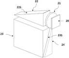
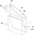
먼저, 도 2는 본 발명에 따른 웨지프리즘을 사용한 투과형 헤드마운트 디스플레이 광학시스템의 구성 및 배치에 대한 실시예를 개략적으로 나타낸 도면이고, 도 3은 영상광의 이동경로를 3차원적으로 표시한 개략도이다.First, FIG. 2 is a view schematically showing an embodiment of the configuration and arrangement of a transmissive head mounted display optical system using a wedge prism according to the present invention, and FIG. 3 is a schematic view showing three-dimensionally the movement path of image light. .
본 발명에 따른 투과형 헤드마운트 디스플레이 광학시스템은 도 2와 3에 도시된 바와 같이, 디스플레이 소자(20)와, 콜리메이션 렌즈(21)와, 제 1 웨지프리즘(22)과, 제 2 웨지프리즘(23) 및 제 3 웨지프리즘(24)를 포함하여 이루어진다.The transmissive head mounted display optical system according to the present invention has a
상기와 같은 구성에 의하여, 본 발명에 따른 투과형 헤드마운트 디스플레이 광학시스템은 디스플레이 소자(20)에서 발산하는 영상광이 상기 디스플레이 소자(20)와 평행하게 광축이 일치되도록 위치한 콜리메이션 렌즈(21)을 통하여 평행광으로 바뀐 뒤, 제 1 웨지프리즘(22) 내부로 입사하여 수평방향으로 평행하게 진행하며, 제 1 웨지프리즘(22) 경사면에 설치된 수평방향 확대수단(221)에 의해 수평방향으로 영상의 크기가 확대된 후 수직 하방으로 반사되어 상기 제 1 웨지프리즘(22)으로부터 출사된다. 또한 제 1 웨지프리즘(22)의 수직 하방으로 반사된 영상광은 제1 웨지프리즘(22)의 하방에 위치한 상기 제 2 웨지프리즘(23)으로 입사되고, 제 2 웨지프리즘(23)의 경사면에 위치한 수직방향 확대수단(231)에 의하여 수직방향으로 영상의 크기가 확대된 후 수직 전방으로 반사되어, 제 2 웨지프리즘(23)으로부터 출사됨으로써 사용자는 최초 디스플레이 소자의 크기보다 수평 및 수직 방향으로 크게 확대된 영상을 시청할 수 있게 된다.According to the above configuration, the transmissive head mounted display optical system according to the present invention uses the
이때, 수평방향으로의 영상 확대와 수직방향으로의 영상 확대의 비율을 동일하게 하여 영상의 왜곡을 최소화하기 위해서는 상기 제 1 웨지프리즘(22)과 상기 제 2 웨지프리즘(23)의 경사각을 동일하게 하여야 한다.In this case, in order to minimize the distortion of the image by equalizing the ratio of image magnification in the horizontal direction to image magnification in the vertical direction, the inclination angles of the
또한, 상기 제 2 웨지프리즘(23) 후면에 배치된 상기 제 3 웨지프리즘(24)은 상기 제 2 웨지프리즘(23)의 수직방향 확대수단(231)이 홀로그래픽 광학소자일 경우 경사면을 평면으로 하며 상기 제 2 웨지프리즘(23)의 수직방향 확대수단(231)이 회절광학소자(DOE)일 경우 상기 제 2 웨지 프리즘(23)의 회절광학소자와 역의 톱니 형상을 보유하여 사용자가 외부 영상을 왜곡 없이 볼 수 있도록 보상된 광학계를 제공한다.In addition, the
도 4a는 상기 제 1 웨지프리즘(22)에서 경사면에 수평방향 확대수단을 보유하고 있지 못할 경우의 일반적인 영상광의 진로를 도식화한 도면으로서, 도 4a에 의하면 경사면의 입사각θ과 반사각θ'은 동일해야 하므로, 입사 영상광의 폭 d와 반사 영상광의 폭 d'는 동일하므로 확대효과가 없다.4A is a diagram illustrating a general image light path when the
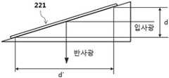
도 4b는 상기 제 1 웨지프리즘에서(22)에서 경사면에 수평방향 확대수단(221)으로서 홀로그래픽 광학소자(HOE)를 보유하고 있을 경우 영상광의 진로를 도식화한 도면으로서, 도 4b에 의하면 수평방향으로 경사면에 입사한 영상광은 상기 홀로그래픽 광학소자(221) 내부에 이미지 신호의 파장에 따라 회절되는 각도가 결정되어지도록 미리 입력된 패턴 무늬가 포함되어 있어 이미 입력된 수직 하방으로 영상광을 반사시킨다.FIG. 4B is a diagram illustrating the path of the image light when the
상기 홀로그래픽 광학소자(221)에 회절각도를 미리 입력하기 위해서는 도 4c에 도시된 바와 같이, 상기 홀로그래픽 광학소자(221)의 반대방향에서 레이저 입사빔(Object Beam)이 수평하게 입사되고, 또 다른 레이저 빔(Reference Beam)은 경사각을 가지고 조사되면, 상기 홀로그래픽 광학소자(221)의 내부에 회절각도가 미리 입력된 패턴 무늬로 새겨진다. 이와 같이 입력을 마친 후, 입력에 사용된 레이저 빔(Object Beam)과 동일한 파장대역의 영상광을, 입력시 사용하였던 레이저 빔(Reference Beam)와 동일한 각도로 조사하면 미리 입력된 패턴 무늬에 의해 영상광은 상기 레이저 입사빔(Object Beam)의 반대 방향으로 영상광을 반사하며, 이때 영상광의 광폭 d는 d'로 확대되어 반사된다. 이러한 이론 및 시험은 학술적으로 검증되어 여러 분야에서 응용되고 있다.In order to input the diffraction angle to the holographic
또한, 상기 홀로그래픽 광학소자(221)는 색의 3원색인 R, G, B 에 대하여 각각의 레이저를 이용하여 패턴 무늬를 입력할 수 있으므로 색채(Color) 구현을 위해서는 동일한 홀로그래픽 광학소자에 RGB 레이저를 동시에 조사함으로써 패턴무늬를 입력하거나 RGB 각각의 패턴 무늬가 입력된 홀로그래픽 광학소자를 만든 후 적층 방식으로 경사면에 부착할 수도 있다. 일반적으로 상기 홀로그래픽 광학소자(221)에는 포토폴리머가 사용된다.In addition, since the holographic
도 4d는 상기 제 1 웨지프리즘에서(22)에서 경사면에 수평방향 확대수단(221)으로서 회절광학소자(DOE)를 보유하고 있을 경우 영상광의 진로를 도식화한 도면으로서, 도 4d에 의하면 수평방향으로 경사면에 입사한 영상광 d는 상기 회절광학소자(221) 표면에 돌출된 톱니 모양의 반사면에 의해 수직 하방으로 영상광 d'가 되어 확대된 상태로 반사된다. 이때, 각 톱니 구조의 간격은 가시 광선의 파장보다 커야만 하므로 적어도 10㎛이어야 하며 사람의 눈의 눈동자의 크기를 감안하면 200 ㎛이하이다. 가장 이상적인 톱니의 간격은 회절 격자선을 인간의 눈으로 인식이 가능한 한계가 50 ㎛임을 감안하면 10~50 ㎛ 사이이고, 깊이는 회절격자의 간격과 경사면의 각도, 그리고 회절격자면의 각도의 함수에 의해 결정된다. 상기 수평방향 확대수단(221)인 회절광학 소자(DOE)의 외부면은 상기 제 2 웨지프리즘(23) 내부에서 반사되는 영상광이 모두 반사될 수 있도록 100% 반사 미러 코팅 처리한다.FIG. 4D is a diagram illustrating a path of image light when the
도 5a는 상기 제 2 웨지프리즘(23)에서 경사면에 수직방향 확대수단을 보유하고 있지 못할 경우 일반적인 영상광의 진로를 도식화한 도면으로서, 도 5a에 의하면 경사면의 입사각θ와 반사각θ’는 동일해야 하므로, 입사 영상광의 폭 d는 반사 영상광의 폭 d'는 동일하여 확대효과가 없다.FIG. 5A is a diagram illustrating a general image light path when the
도 5b는 상기 제 2 웨지프리즘에서(23)에서 경사면에 수직방향 확대수단(231)으로서 홀로그래픽 광학소자(HOE)를 보유하고 있을 경우 영상광의 진로를 도식화한 도면으로서, 도 5b에 의하면, 도 4b에서 제시된 바와 같이 동일한 원리에 의하여 수직방향으로 경사면에 입사한 영상광은 상기 홀로그래픽 광학소자(231) 내부에 이미지 신호의 파장에 따라 회절되는 각도가 결정되어지도록 미리 입력된 패턴 무늬가 포함되어 있어 이미 입력된 수평 전방으로 영상광을 반사시킨다.FIG. 5B is a diagram illustrating the path of the image light when the
도 5c는 상기 제 2 웨지프리즘에서(23)에서 경사면에 수평방향 확대수단(231)으로서 회절광학소자(DOE)를 보유하고 있을 경우 영상광의 진로를 도식화한 도면으로서, 도 5c에 의하면, 도 4d에서 제시된 바와 같이 동일한 원리에 의하여 수직방향으로 경사면에 입사한 영상광 d는 상기 회절광학소자(231) 표면에 돌출된 톱니 모양의 반사면에 의해 수평 전방으로 영상광 d'가 되어 확대된 상태로 반사된다. 상기 수직방향 확대수단(231)인 회절광학 소자(DOE)의 외부면은 상기 제 2 웨지프리즘(23) 내부에서 반사되는 영상광과 외부로부터 투과되는 영상광이 모두 동시에 보일 수 있도록 하프미러 코팅 처리한다.FIG. 5C is a diagram illustrating the path of image light when the
도 6은 도 2에 제시된 본 발명의 투과형 헤드마운트 디스플레이 시스템 중 상기 콜리메이션 렌즈(21)와 상기 제 1 웨지프리즘(22) 사이에 45도 반사판(211)을 추가함으로써 상기 디스플레이 소자(20)와 상기 콜리메이션 렌즈(211)를 안경테 안에 넣을 수 있는 구조로 배열이 가능하도록 한 일 실시예를 나타낸 것이다.FIG. 6 shows the
상기와 같은 구성에 의하여 상기 디스플레이 소자(20)에서 발산하는 영상광은 상기 디스플레이 소자와 평행하게 광축이 일치되도록 위치한 상기 콜리메이션 렌즈(21)를 통하여 평행광으로 바뀐 뒤 상기 45도 반사판에서 90도 회전하여 상기 제 1 웨지프리즘(22) 내부로 입사하며, 도 2를 통해 전술한 바와 같이 수평 및 수직방향의 확대 수단에 의해 사용자에게 확대된 영상이 제공된다.According to the configuration described above, the image light emitted from the
도 7은 도 2에 제시된 본 발명의 투과형 헤드마운트 디스플레이 시스템 중 상기 제 1 웨지프리즘(22)과 상기 제 2 웨지프리즘(23) 사이에 수평 방향과 수직 방향의 영상을 추가로 확대할 수 있는 수단인 파워를 가진 렌즈(703)을 추가함으로써 시야각(FOV)를 더욱 크게 할 수 있도록 하는 일실시예를 나타낸 것이다.7 is a means for further enlarging an image in a horizontal direction and a vertical direction between the
위와 같은 구성으로 이루어지는 본 발명에 따른 투과형 헤드마운트 디스플레이 광학시스템은 제 1 웨지프리즘(22)에서 제공하는 수평방향 확대수단과 제 2 웨지프리즘(23)에서 제공하는 수직방향 확대 수단을 이용하여 영상을 확대할 수 있으므로 상의 확대를 위한 렌즈 사용을 최소화할 수 있을 뿐 아니라 얇은 두께에도 불구하고 대화면을 시청할 수 있도록 영상을 확대할 수 있다. 또한, 하프미러와 같이 광 손실을 강제하는 수단의 사용을 최대한 억제함으로써 원화상과 거의 동등한 수준의 매우 밝고 선명한 화상을 제공할 수 있다.The transmissive head-mounted display optical system according to the present invention having the above configuration has an image using a horizontal enlargement means provided by the
한편 본 발명의 상세한 설명에서는 구체적인 실시 예에 관해 설명하였으나, 본 발명의 범위에서 벗어나지 않는 한도 내에서 여러 가지 변형이 가능함은 물론이다. 그러므로 본 발명의 범위는 설명된 실시 예에 국한되어 정해져서는 안되며 후술하는 특허청구의 범위뿐 아니라 이 특허청구의 범위와 균등한 것들에 의해서 정해져야 한다.
While the present invention has been described in connection with what is presently considered to be the most practical and preferred embodiment, it is to be understood that the invention is not limited to the disclosed embodiments, but is capable of various modifications within the scope of the invention. Therefore, the scope of the present invention should not be limited by the described embodiments, but should be determined by the scope of the appended claims and equivalents thereof.
20 : 디스플레이 소자21 : 콜리메이션 렌즈
22 : 제 1 웨지프리즘221 : 영상 수평확대 수단
23 : 제 2 웨지프리즘231 : 영상 수직확대 수단
24 : 제 3 웨지프리즘20
22: first wedge prism 221: image horizontal expansion means
23: second wedge prism 231: vertical vertical expansion means
24: Third Wedge Prism
Claims (12)
Translated fromKorean상기 디스플레이 소자부터 발산되는 영상광을 평행하게 만들어주는 콜리메이션 렌즈;
상기 콜리메이션 렌즈를 통과하여 평행하게 정렬된 영상광이 입사되어 수평방향으로 영상을 확대할 수 있도록 제 1 확대수단을 구비하는 제 1 웨지프리즘;
상기 제 1 웨지프리즘을 통과하여 수평방향으로 확대된 영상광이 입사하여 수직방향으로 영상을 확대할 수 있도록 제 2 확대수단을 구비하는 제 2 웨지프리즘; 및
상기 제 2 웨지프리즘에서 반사되어 수직방향으로 확대된 영상광과 상기 제 2 웨지프리즘을 투과하여 사용자에게 제공되는 외부 영상이 왜곡되지 않도록 상기 제 2 웨지프리즘과 역의 형상을 가진 제 3 웨지프리즘;을 포함하는 투과형 헤드마운트 디스플레이 광학시스템.
Display elements;
A collimation lens for parallelizing the image light emitted from the display element;
A first wedge prism having first magnification means for enlarging the image light aligned in parallel through the collimation lens to expand the image in a horizontal direction;
A second wedge prism having a second magnification means for enlarging the image light in a horizontal direction through the first wedge prism and expanding the image light in a vertical direction; And
A third wedge prism having a shape opposite to that of the second wedge prism such that the image light reflected from the second wedge prism and enlarged in the vertical direction and an external image transmitted to the user through the second wedge prism are not distorted; Transmissive headmount display optical system comprising a.
내부에 격자 구조를 형성하여 반사각의 방향을 원하는 방향으로 바꿀 수 있는 홀로그래픽 광학소자(HOE)인 것을 특징으로 하는 투과형 헤드마운트 디스플레이 광학시스템.
The method of claim 1, wherein the first magnification means for enlarging the horizontal image provided in the first wedge prism,
A transmissive head mounted display optical system, characterized in that it is a holographic optical element (HOE) which can form a lattice structure therein and change the direction of reflection angle to a desired direction.
반사면이 반사각의 방향을 원하는 방향으로 바꿀 수 있도록 경사각을 가진 톱니 구조의 회절 광학소자(DOE)인 것을 특징으로 하는 투과형 헤드마운트 디스플레이 광학시스템.
The method of claim 1, wherein the first magnification means for enlarging the horizontal image provided in the first wedge prism,
A transmissive head mounted display optical system, characterized in that the reflecting surface is a toothed diffractive optical element (DOE) having an inclination angle so as to change the direction of the reflection angle in a desired direction.
내부에 격자 구조를 형성하여 반사각의 방향을 원하는 방향으로 바꿀 수 있는 홀로그래픽 광학소자(HOE)인 것을 특징으로 하는 투과형 헤드마운트 디스플레이 광학시스템.
The method of claim 1, wherein the second magnification means for enlarging the vertical image of the second wedge prism,
A transmissive head mounted display optical system, characterized in that it is a holographic optical element (HOE) which can form a lattice structure therein and change the direction of reflection angle to a desired direction.
반사면이 반사각의 방향을 원하는 방향으로 바꿀 수 있도록 경사각을 가진 톱니 구조의 회절 광학소자(DOE)인 것을 특징으로 하는 투과형 헤드마운트 디스플레이 광학시스템.
The method of claim 1, wherein the second magnification means for enlarging the vertical image of the second wedge prism,
A transmissive head mounted display optical system, characterized in that the reflecting surface is a toothed diffractive optical element (DOE) having an inclination angle so as to change the direction of the reflection angle in a desired direction.
상기 제 2 웨지프리즘의 경사면이 회절광학소자(DOE)일 경우, 제 2 웨지 프리즘과 역의 톱니 형상을 갖는 경사면을 보유하여 사용자가 외부 영상을 왜곡 없이 볼 수 있도록 보상된 광학계를 제공하는 것을 특징으로 하는 투과형 헤드마운트 디스플레이 광학시스템.
The method of claim 1, wherein the third wedge prism,
When the inclined surface of the second wedge prism is a diffractive optical element (DOE), the inclined surface having a sawtooth shape opposite to the second wedge prism is provided to provide a compensated optical system so that a user can see an external image without distortion. Transmissive head mounted display optical system.
시야각(FOV)을 확대하기 위하여 상기 제 1 웨지프리즘과 상기 제 2 웨지프리즘의 사이에 볼록렌즈를 더 구비하는 것을 특징으로 하는 투과형 헤드마운트 디스플레이 광학시스템.
The method of claim 1,
And a convex lens between the first wedge prism and the second wedge prism for enlarging a field of view (FOV).
상기 제 1 웨지프리즘과 상기 제 2 웨지프리즘의 경사각을 동일하게 하여, 영상광의 수평확대와 수직확대의 비율을 동일하도록 함으로써 영상왜곡을 최소화하는 것을 특징으로 하는 투과형 헤드마운트 디스플레이 광학시스템.
The method of claim 1,
And the image distortion is minimized by making the inclination angles of the first wedge prism and the second wedge prism equal to each other so that the ratio of horizontal magnification and vertical magnification of the image light is the same.
상기 반사면이 100% 반사 코팅면인 것을 특징으로 하는 투과형 헤드마운트 디스플레이 광학시스템.
The method of claim 3, wherein the first expanding means,
And the reflective surface is a 100% reflective coating surface.
상기 반사면이 50 % 하프미러 코팅면인 것을 특징으로 하는 투과형 헤드마운트 디스플레이 광학시스템.
The method of claim 5, wherein the second expanding means,
And said reflective surface is a 50% half mirror coating surface.
반사형 홀로그래픽 광학소자(HOE)인 것을 특징으로 하는 투과형 헤드마운트 디스플레이 광학시스템.
The method of claim 2, wherein the first expanding means,
A transmissive head mounted display optical system, characterized in that it is a reflective holographic optical element (HOE).
반사형 홀로그래픽 광학소자(HOE)인 것을 특징으로 하는 투과형 헤드마운트 디스플레이 광학시스템.The method of claim 4, wherein the second expanding means,
A transmissive head mounted display optical system, characterized in that it is a reflective holographic optical element (HOE).
Priority Applications (1)
| Application Number | Priority Date | Filing Date | Title |
|---|---|---|---|
| KR1020120142770AKR101361096B1 (en) | 2012-12-10 | 2012-12-10 | Optical system for see-through head mounted display |
Applications Claiming Priority (1)
| Application Number | Priority Date | Filing Date | Title |
|---|---|---|---|
| KR1020120142770AKR101361096B1 (en) | 2012-12-10 | 2012-12-10 | Optical system for see-through head mounted display |
Publications (1)
| Publication Number | Publication Date |
|---|---|
| KR101361096B1true KR101361096B1 (en) | 2014-02-12 |
Family
ID=50270494
Family Applications (1)
| Application Number | Title | Priority Date | Filing Date |
|---|---|---|---|
| KR1020120142770AExpired - Fee RelatedKR101361096B1 (en) | 2012-12-10 | 2012-12-10 | Optical system for see-through head mounted display |
Country Status (1)
| Country | Link |
|---|---|
| KR (1) | KR101361096B1 (en) |
Cited By (11)
| Publication number | Priority date | Publication date | Assignee | Title |
|---|---|---|---|---|
| KR101591937B1 (en)* | 2014-02-11 | 2016-02-05 | (주)그린광학 | Surgical head mounted display |
| KR101815732B1 (en)* | 2015-05-27 | 2018-01-05 | 한국광기술원 | Optics device using anamorphic lens |
| CN108121069A (en)* | 2016-11-30 | 2018-06-05 | 精工爱普生株式会社 | Image display and guiding device |
| KR20190002985U (en)* | 2018-05-27 | 2019-12-05 | 루머스 리미티드 | Substrate-Guide Based Optical Systems with Field Curvature Effect Mitigation |
| KR102072012B1 (en)* | 2018-12-14 | 2020-01-31 | (주)비젼에이드 | Head mounted display device |
| KR102072008B1 (en)* | 2018-12-14 | 2020-01-31 | (주)비젼에이드 | Head mounted display device |
| WO2020045916A1 (en)* | 2018-08-27 | 2020-03-05 | 주식회사 파노비젼 | Transmissive hmd optical system having periscope type forward-looking means |
| KR20210042217A (en)* | 2019-10-08 | 2021-04-19 | 삼성전자주식회사 | Augmented reality device including a flat combiner and electronic device including the same |
| CN113189777A (en)* | 2021-04-25 | 2021-07-30 | 深圳市光舟半导体技术有限公司 | Binocular AR eyepiece vision correction system |
| CN114114689A (en)* | 2014-04-23 | 2022-03-01 | 鲁姆斯有限公司 | Compact head-mounted display system |
| WO2023058997A1 (en)* | 2021-10-05 | 2023-04-13 | 주식회사 엘지화학 | Display device |
Citations (4)
| Publication number | Priority date | Publication date | Assignee | Title |
|---|---|---|---|---|
| JP2002228971A (en) | 2001-02-05 | 2002-08-14 | Mixed Reality Systems Laboratory Inc | Image display device |
| KR20030013640A (en)* | 2001-08-08 | 2003-02-15 | 엘지전자 주식회사 | See-around type head mounted display device |
| JP2009134087A (en) | 2007-11-30 | 2009-06-18 | Konica Minolta Holdings Inc | Image display device and head mount display |
| US20100290127A1 (en)* | 2009-05-13 | 2010-11-18 | NVIS Inc. | Head-mounted optical apparatus using an oled display |
- 2012
- 2012-12-10KRKR1020120142770Apatent/KR101361096B1/ennot_activeExpired - Fee Related
Patent Citations (4)
| Publication number | Priority date | Publication date | Assignee | Title |
|---|---|---|---|---|
| JP2002228971A (en) | 2001-02-05 | 2002-08-14 | Mixed Reality Systems Laboratory Inc | Image display device |
| KR20030013640A (en)* | 2001-08-08 | 2003-02-15 | 엘지전자 주식회사 | See-around type head mounted display device |
| JP2009134087A (en) | 2007-11-30 | 2009-06-18 | Konica Minolta Holdings Inc | Image display device and head mount display |
| US20100290127A1 (en)* | 2009-05-13 | 2010-11-18 | NVIS Inc. | Head-mounted optical apparatus using an oled display |
Cited By (14)
| Publication number | Priority date | Publication date | Assignee | Title |
|---|---|---|---|---|
| KR101591937B1 (en)* | 2014-02-11 | 2016-02-05 | (주)그린광학 | Surgical head mounted display |
| CN114114689A (en)* | 2014-04-23 | 2022-03-01 | 鲁姆斯有限公司 | Compact head-mounted display system |
| KR101815732B1 (en)* | 2015-05-27 | 2018-01-05 | 한국광기술원 | Optics device using anamorphic lens |
| CN108121069A (en)* | 2016-11-30 | 2018-06-05 | 精工爱普生株式会社 | Image display and guiding device |
| KR20190002985U (en)* | 2018-05-27 | 2019-12-05 | 루머스 리미티드 | Substrate-Guide Based Optical Systems with Field Curvature Effect Mitigation |
| KR200497882Y1 (en) | 2018-05-27 | 2024-03-21 | 루머스 리미티드 | Substrate-Guide Based Optical Systems with Field Curvature Effect Mitigation |
| WO2020045916A1 (en)* | 2018-08-27 | 2020-03-05 | 주식회사 파노비젼 | Transmissive hmd optical system having periscope type forward-looking means |
| KR102072008B1 (en)* | 2018-12-14 | 2020-01-31 | (주)비젼에이드 | Head mounted display device |
| KR102072012B1 (en)* | 2018-12-14 | 2020-01-31 | (주)비젼에이드 | Head mounted display device |
| KR20210042217A (en)* | 2019-10-08 | 2021-04-19 | 삼성전자주식회사 | Augmented reality device including a flat combiner and electronic device including the same |
| KR102800329B1 (en)* | 2019-10-08 | 2025-04-29 | 삼성전자주식회사 | Augmented reality device including a flat combiner and electronic device including the same |
| CN113189777A (en)* | 2021-04-25 | 2021-07-30 | 深圳市光舟半导体技术有限公司 | Binocular AR eyepiece vision correction system |
| CN113189777B (en)* | 2021-04-25 | 2021-12-14 | 深圳市光舟半导体技术有限公司 | Binocular AR eyepiece vision correction system |
| WO2023058997A1 (en)* | 2021-10-05 | 2023-04-13 | 주식회사 엘지화학 | Display device |
Similar Documents
| Publication | Publication Date | Title |
|---|---|---|
| KR101361096B1 (en) | Optical system for see-through head mounted display | |
| Bang et al. | Lenslet VR: thin, flat and wide-FOV virtual reality display using fresnel lens and lenslet array | |
| JP6867999B2 (en) | Imaging light guide with reflective conversion array | |
| JP7222968B2 (en) | Display device for expanding the field of view | |
| JP6736911B2 (en) | Luminous flux diameter expanding element and image display device | |
| US9575318B2 (en) | Optical system for see-through head mounted display having three wedge prism arrangement for separate enlargement in vertical and horizontal directions | |
| TWI656357B (en) | Display device | |
| RU2579804C1 (en) | Optical device for generating augmented reality images | |
| US8773599B2 (en) | Near-to-eye display with diffraction grating that bends and focuses light | |
| JP5060704B2 (en) | Flat projection display | |
| JP6337656B2 (en) | Image display device | |
| JP6519256B2 (en) | Beam diameter expanding element and display device | |
| RU2719568C1 (en) | Augmented reality device and method of its operation | |
| WO2017107313A1 (en) | Naked eye 3d laser display device | |
| CN105929535A (en) | Image display device | |
| EP3998506B1 (en) | Near-eye display device, augmented reality glasses including same, and operating method therefor | |
| EP4133325B1 (en) | Waveguide display with cross-polarized eye pupil expanders | |
| WO2016143246A1 (en) | Image display device | |
| US11269189B2 (en) | Image display device | |
| TW201708884A (en) | Image display device | |
| TWI866315B (en) | Display system | |
| JP2015184385A (en) | image display device | |
| CN108333781B (en) | Near-to-eye display system | |
| WO2022008378A1 (en) | Reflective in-coupler design with high refractive index element using second diffraction order for near-eye displays | |
| JP5842298B2 (en) | Transmission head-mounted display optical system |
Legal Events
| Date | Code | Title | Description |
|---|---|---|---|
| A201 | Request for examination | ||
| PA0109 | Patent application | St.27 status event code:A-0-1-A10-A12-nap-PA0109 | |
| PA0201 | Request for examination | St.27 status event code:A-1-2-D10-D11-exm-PA0201 | |
| PN2301 | Change of applicant | St.27 status event code:A-3-3-R10-R13-asn-PN2301 St.27 status event code:A-3-3-R10-R11-asn-PN2301 | |
| PN2301 | Change of applicant | St.27 status event code:A-3-3-R10-R13-asn-PN2301 St.27 status event code:A-3-3-R10-R11-asn-PN2301 | |
| D13-X000 | Search requested | St.27 status event code:A-1-2-D10-D13-srh-X000 | |
| D14-X000 | Search report completed | St.27 status event code:A-1-2-D10-D14-srh-X000 | |
| E701 | Decision to grant or registration of patent right | ||
| PE0701 | Decision of registration | St.27 status event code:A-1-2-D10-D22-exm-PE0701 | |
| GRNT | Written decision to grant | ||
| PR0701 | Registration of establishment | St.27 status event code:A-2-4-F10-F11-exm-PR0701 | |
| PR1002 | Payment of registration fee | St.27 status event code:A-2-2-U10-U11-oth-PR1002 Fee payment year number:1 | |
| PG1601 | Publication of registration | St.27 status event code:A-4-4-Q10-Q13-nap-PG1601 | |
| P14-X000 | Amendment of ip right document requested | St.27 status event code:A-5-5-P10-P14-nap-X000 | |
| R18-X000 | Changes to party contact information recorded | St.27 status event code:A-5-5-R10-R18-oth-X000 | |
| P22-X000 | Classification modified | St.27 status event code:A-4-4-P10-P22-nap-X000 | |
| FPAY | Annual fee payment | Payment date:20161207 Year of fee payment:4 | |
| PR1001 | Payment of annual fee | St.27 status event code:A-4-4-U10-U11-oth-PR1001 Fee payment year number:4 | |
| FPAY | Annual fee payment | Payment date:20180201 Year of fee payment:5 | |
| PR1001 | Payment of annual fee | St.27 status event code:A-4-4-U10-U11-oth-PR1001 Fee payment year number:5 | |
| P22-X000 | Classification modified | St.27 status event code:A-4-4-P10-P22-nap-X000 | |
| FPAY | Annual fee payment | Payment date:20190307 Year of fee payment:6 | |
| PR1001 | Payment of annual fee | St.27 status event code:A-4-4-U10-U11-oth-PR1001 Fee payment year number:6 | |
| PC1903 | Unpaid annual fee | St.27 status event code:A-4-4-U10-U13-oth-PC1903 Not in force date:20200205 Payment event data comment text:Termination Category : DEFAULT_OF_REGISTRATION_FEE | |
| PC1903 | Unpaid annual fee | St.27 status event code:N-4-6-H10-H13-oth-PC1903 Ip right cessation event data comment text:Termination Category : DEFAULT_OF_REGISTRATION_FEE Not in force date:20200205 |