KR101359956B1 - Method for preparing a filtration membrane and filtration membrane prepared by said method - Google Patents
Method for preparing a filtration membrane and filtration membrane prepared by said methodDownload PDFInfo
- Publication number
- KR101359956B1 KR101359956B1KR1020110098408AKR20110098408AKR101359956B1KR 101359956 B1KR101359956 B1KR 101359956B1KR 1020110098408 AKR1020110098408 AKR 1020110098408AKR 20110098408 AKR20110098408 AKR 20110098408AKR 101359956 B1KR101359956 B1KR 101359956B1
- Authority
- KR
- South Korea
- Prior art keywords
- membrane
- support
- fabric
- composite
- film
- Prior art date
- Legal status (The legal status is an assumption and is not a legal conclusion. Google has not performed a legal analysis and makes no representation as to the accuracy of the status listed.)
- Active
Links
- 239000012528membraneSubstances0.000titleclaimsabstractdescription239
- 238000000034methodMethods0.000titleclaimsabstractdescription74
- 238000001914filtrationMethods0.000titleclaimsabstractdescription50
- 239000002131composite materialSubstances0.000claimsabstractdescription92
- 229920000642polymerPolymers0.000claimsabstractdescription47
- 238000004519manufacturing processMethods0.000claimsabstractdescription40
- 239000002390adhesive tapeSubstances0.000claimsabstractdescription29
- 238000005266castingMethods0.000claimsabstractdescription7
- 239000004744fabricSubstances0.000claimsdescription48
- 239000004952PolyamideSubstances0.000claimsdescription27
- 229920002647polyamidePolymers0.000claimsdescription27
- -1polyethylene terephthalatePolymers0.000claimsdescription20
- 238000000108ultra-filtrationMethods0.000claimsdescription18
- 238000004804windingMethods0.000claimsdescription18
- 229920006254polymer filmPolymers0.000claimsdescription14
- 238000001035dryingMethods0.000claimsdescription12
- 238000001471micro-filtrationMethods0.000claimsdescription12
- 229920000139polyethylene terephthalatePolymers0.000claimsdescription12
- 239000005020polyethylene terephthalateSubstances0.000claimsdescription12
- 239000000463materialSubstances0.000claimsdescription10
- 239000004743PolypropyleneSubstances0.000claimsdescription9
- 239000004745nonwoven fabricSubstances0.000claimsdescription9
- 229920001155polypropylenePolymers0.000claimsdescription9
- 238000004080punchingMethods0.000claimsdescription9
- 238000010791quenchingMethods0.000claimsdescription9
- 230000000171quenching effectEffects0.000claimsdescription9
- 230000000149penetrating effectEffects0.000claimsdescription6
- 229920001721polyimidePolymers0.000claimsdescription6
- 229920002492poly(sulfone)Polymers0.000claimsdescription4
- 229920005597polymer membranePolymers0.000claimsdescription4
- 239000004698PolyethyleneSubstances0.000claimsdescription3
- 239000004642PolyimideSubstances0.000claimsdescription3
- NIXOWILDQLNWCW-UHFFFAOYSA-Nacrylic acid groupChemical groupC(C=C)(=O)ONIXOWILDQLNWCW-UHFFFAOYSA-N0.000claimsdescription3
- 229920006289polycarbonate filmPolymers0.000claimsdescription3
- 229920006393polyether sulfonePolymers0.000claimsdescription3
- 229920000573polyethylenePolymers0.000claimsdescription3
- 239000004695Polyether sulfoneSubstances0.000claims2
- 239000000243solutionSubstances0.000description46
- 239000010408filmSubstances0.000description39
- XLYOFNOQVPJJNP-UHFFFAOYSA-NwaterSubstancesOXLYOFNOQVPJJNP-UHFFFAOYSA-N0.000description14
- PEDCQBHIVMGVHV-UHFFFAOYSA-NGlycerineChemical compoundOCC(O)COPEDCQBHIVMGVHV-UHFFFAOYSA-N0.000description12
- 238000001223reverse osmosisMethods0.000description12
- 239000002904solventSubstances0.000description10
- 238000009292forward osmosisMethods0.000description9
- ZMXDDKWLCZADIW-UHFFFAOYSA-NN,N-DimethylformamideChemical compoundCN(C)C=OZMXDDKWLCZADIW-UHFFFAOYSA-N0.000description6
- 239000007864aqueous solutionSubstances0.000description6
- 230000004907fluxEffects0.000description6
- 230000035699permeabilityEffects0.000description6
- 230000008569processEffects0.000description6
- 229920003171Poly (ethylene oxide)Polymers0.000description5
- 238000004299exfoliationMethods0.000description5
- 239000007787solidSubstances0.000description5
- 230000008901benefitEffects0.000description4
- 239000011148porous materialSubstances0.000description4
- 239000007795chemical reaction productSubstances0.000description3
- 238000010612desalination reactionMethods0.000description3
- 238000010586diagramMethods0.000description3
- 239000012467final productSubstances0.000description3
- 239000000203mixtureSubstances0.000description3
- 230000003204osmotic effectEffects0.000description3
- 150000003839saltsChemical class0.000description3
- 239000006104solid solutionSubstances0.000description3
- 238000012360testing methodMethods0.000description3
- 239000010409thin filmSubstances0.000description3
- 239000002759woven fabricSubstances0.000description3
- WZCQRUWWHSTZEM-UHFFFAOYSA-N1,3-phenylenediamineChemical compoundNC1=CC=CC(N)=C1WZCQRUWWHSTZEM-UHFFFAOYSA-N0.000description2
- 238000012695Interfacial polymerizationMethods0.000description2
- 239000004677NylonSubstances0.000description2
- FAPWRFPIFSIZLT-UHFFFAOYSA-MSodium chlorideChemical compound[Na+].[Cl-]FAPWRFPIFSIZLT-UHFFFAOYSA-M0.000description2
- 150000001266acyl halidesChemical class0.000description2
- 150000001412aminesChemical class0.000description2
- UWCPYKQBIPYOLX-UHFFFAOYSA-Nbenzene-1,3,5-tricarbonyl chlorideChemical compoundClC(=O)C1=CC(C(Cl)=O)=CC(C(Cl)=O)=C1UWCPYKQBIPYOLX-UHFFFAOYSA-N0.000description2
- 230000008859changeEffects0.000description2
- 230000032798delaminationEffects0.000description2
- 238000000151depositionMethods0.000description2
- 238000007598dipping methodMethods0.000description2
- 239000012530fluidSubstances0.000description2
- 238000012986modificationMethods0.000description2
- 230000004048modificationEffects0.000description2
- 229920001778nylonPolymers0.000description2
- 230000003287optical effectEffects0.000description2
- 230000035515penetrationEffects0.000description2
- 239000012466permeateSubstances0.000description2
- 238000012545processingMethods0.000description2
- 239000000047productSubstances0.000description2
- 239000013535sea waterSubstances0.000description2
- 239000000758substrateSubstances0.000description2
- RWLALWYNXFYRGW-UHFFFAOYSA-N2-Ethyl-1,3-hexanediolChemical compoundCCCC(O)C(CC)CORWLALWYNXFYRGW-UHFFFAOYSA-N0.000description1
- 229920002799BoPETPolymers0.000description1
- 239000002033PVDF binderSubstances0.000description1
- 229920000297RayonPolymers0.000description1
- 239000000853adhesiveSubstances0.000description1
- 230000001070adhesive effectEffects0.000description1
- ZEYWAHILTZGZBH-UHFFFAOYSA-Nazane;carbon dioxideChemical compoundN.O=C=OZEYWAHILTZGZBH-UHFFFAOYSA-N0.000description1
- 229920002301cellulose acetatePolymers0.000description1
- 230000003111delayed effectEffects0.000description1
- 230000008021depositionEffects0.000description1
- 238000011161developmentMethods0.000description1
- 230000018109developmental processEffects0.000description1
- 230000005611electricityEffects0.000description1
- 239000000835fiberSubstances0.000description1
- 239000011521glassSubstances0.000description1
- 238000004128high performance liquid chromatographyMethods0.000description1
- 238000007654immersionMethods0.000description1
- 238000010297mechanical methods and processMethods0.000description1
- 230000005226mechanical processes and functionsEffects0.000description1
- 239000012046mixed solventSubstances0.000description1
- 239000002245particleSubstances0.000description1
- 229920002981polyvinylidene fluoridePolymers0.000description1
- 238000002360preparation methodMethods0.000description1
- 239000002964rayonSubstances0.000description1
- 238000000926separation methodMethods0.000description1
- 239000011780sodium chlorideSubstances0.000description1
Images


Classifications
- B—PERFORMING OPERATIONS; TRANSPORTING
- B01—PHYSICAL OR CHEMICAL PROCESSES OR APPARATUS IN GENERAL
- B01D—SEPARATION
- B01D61/00—Processes of separation using semi-permeable membranes, e.g. dialysis, osmosis or ultrafiltration; Apparatus, accessories or auxiliary operations specially adapted therefor
- B01D61/14—Ultrafiltration; Microfiltration
- B01D61/145—Ultrafiltration
- B—PERFORMING OPERATIONS; TRANSPORTING
- B01—PHYSICAL OR CHEMICAL PROCESSES OR APPARATUS IN GENERAL
- B01D—SEPARATION
- B01D61/00—Processes of separation using semi-permeable membranes, e.g. dialysis, osmosis or ultrafiltration; Apparatus, accessories or auxiliary operations specially adapted therefor
- B01D61/14—Ultrafiltration; Microfiltration
- B01D61/147—Microfiltration
- B—PERFORMING OPERATIONS; TRANSPORTING
- B01—PHYSICAL OR CHEMICAL PROCESSES OR APPARATUS IN GENERAL
- B01D—SEPARATION
- B01D67/00—Processes specially adapted for manufacturing semi-permeable membranes for separation processes or apparatus
- B—PERFORMING OPERATIONS; TRANSPORTING
- B01—PHYSICAL OR CHEMICAL PROCESSES OR APPARATUS IN GENERAL
- B01D—SEPARATION
- B01D67/00—Processes specially adapted for manufacturing semi-permeable membranes for separation processes or apparatus
- B01D67/0002—Organic membrane manufacture
- B01D67/0009—Organic membrane manufacture by phase separation, sol-gel transition, evaporation or solvent quenching
- B01D67/0013—Casting processes
- B—PERFORMING OPERATIONS; TRANSPORTING
- B01—PHYSICAL OR CHEMICAL PROCESSES OR APPARATUS IN GENERAL
- B01D—SEPARATION
- B01D67/00—Processes specially adapted for manufacturing semi-permeable membranes for separation processes or apparatus
- B01D67/0002—Organic membrane manufacture
- B01D67/0023—Organic membrane manufacture by inducing porosity into non porous precursor membranes
- B01D67/0032—Organic membrane manufacture by inducing porosity into non porous precursor membranes by elimination of segments of the precursor, e.g. nucleation-track membranes, lithography or laser methods
- B—PERFORMING OPERATIONS; TRANSPORTING
- B01—PHYSICAL OR CHEMICAL PROCESSES OR APPARATUS IN GENERAL
- B01D—SEPARATION
- B01D67/00—Processes specially adapted for manufacturing semi-permeable membranes for separation processes or apparatus
- B01D67/0081—After-treatment of organic or inorganic membranes
- B01D67/0088—Physical treatment with compounds, e.g. swelling, coating or impregnation
- B—PERFORMING OPERATIONS; TRANSPORTING
- B01—PHYSICAL OR CHEMICAL PROCESSES OR APPARATUS IN GENERAL
- B01D—SEPARATION
- B01D67/00—Processes specially adapted for manufacturing semi-permeable membranes for separation processes or apparatus
- B01D67/0081—After-treatment of organic or inorganic membranes
- B01D67/0095—Drying
- B—PERFORMING OPERATIONS; TRANSPORTING
- B01—PHYSICAL OR CHEMICAL PROCESSES OR APPARATUS IN GENERAL
- B01D—SEPARATION
- B01D69/00—Semi-permeable membranes for separation processes or apparatus characterised by their form, structure or properties; Manufacturing processes specially adapted therefor
- B01D69/02—Semi-permeable membranes for separation processes or apparatus characterised by their form, structure or properties; Manufacturing processes specially adapted therefor characterised by their properties
- B—PERFORMING OPERATIONS; TRANSPORTING
- B01—PHYSICAL OR CHEMICAL PROCESSES OR APPARATUS IN GENERAL
- B01D—SEPARATION
- B01D69/00—Semi-permeable membranes for separation processes or apparatus characterised by their form, structure or properties; Manufacturing processes specially adapted therefor
- B01D69/10—Supported membranes; Membrane supports
- B01D69/107—Organic support material
- B01D69/1071—Woven, non-woven or net mesh
- B—PERFORMING OPERATIONS; TRANSPORTING
- B01—PHYSICAL OR CHEMICAL PROCESSES OR APPARATUS IN GENERAL
- B01D—SEPARATION
- B01D69/00—Semi-permeable membranes for separation processes or apparatus characterised by their form, structure or properties; Manufacturing processes specially adapted therefor
- B01D69/12—Composite membranes; Ultra-thin membranes
- B01D69/1213—Laminated layers
- B—PERFORMING OPERATIONS; TRANSPORTING
- B01—PHYSICAL OR CHEMICAL PROCESSES OR APPARATUS IN GENERAL
- B01D—SEPARATION
- B01D71/00—Semi-permeable membranes for separation processes or apparatus characterised by the material; Manufacturing processes specially adapted therefor
- B01D71/06—Organic material
- B01D71/56—Polyamides, e.g. polyester-amides
- B—PERFORMING OPERATIONS; TRANSPORTING
- B32—LAYERED PRODUCTS
- B32B—LAYERED PRODUCTS, i.e. PRODUCTS BUILT-UP OF STRATA OF FLAT OR NON-FLAT, e.g. CELLULAR OR HONEYCOMB, FORM
- B32B27/00—Layered products comprising a layer of synthetic resin
- B32B27/06—Layered products comprising a layer of synthetic resin as the main or only constituent of a layer, which is next to another layer of the same or of a different material
- B—PERFORMING OPERATIONS; TRANSPORTING
- B32—LAYERED PRODUCTS
- B32B—LAYERED PRODUCTS, i.e. PRODUCTS BUILT-UP OF STRATA OF FLAT OR NON-FLAT, e.g. CELLULAR OR HONEYCOMB, FORM
- B32B27/00—Layered products comprising a layer of synthetic resin
- B32B27/28—Layered products comprising a layer of synthetic resin comprising synthetic resins not wholly covered by any one of the sub-groups B32B27/30 - B32B27/42
- B32B27/281—Layered products comprising a layer of synthetic resin comprising synthetic resins not wholly covered by any one of the sub-groups B32B27/30 - B32B27/42 comprising polyimides
- B—PERFORMING OPERATIONS; TRANSPORTING
- B32—LAYERED PRODUCTS
- B32B—LAYERED PRODUCTS, i.e. PRODUCTS BUILT-UP OF STRATA OF FLAT OR NON-FLAT, e.g. CELLULAR OR HONEYCOMB, FORM
- B32B27/00—Layered products comprising a layer of synthetic resin
- B32B27/28—Layered products comprising a layer of synthetic resin comprising synthetic resins not wholly covered by any one of the sub-groups B32B27/30 - B32B27/42
- B32B27/285—Layered products comprising a layer of synthetic resin comprising synthetic resins not wholly covered by any one of the sub-groups B32B27/30 - B32B27/42 comprising polyethers
- B—PERFORMING OPERATIONS; TRANSPORTING
- B32—LAYERED PRODUCTS
- B32B—LAYERED PRODUCTS, i.e. PRODUCTS BUILT-UP OF STRATA OF FLAT OR NON-FLAT, e.g. CELLULAR OR HONEYCOMB, FORM
- B32B27/00—Layered products comprising a layer of synthetic resin
- B32B27/28—Layered products comprising a layer of synthetic resin comprising synthetic resins not wholly covered by any one of the sub-groups B32B27/30 - B32B27/42
- B32B27/286—Layered products comprising a layer of synthetic resin comprising synthetic resins not wholly covered by any one of the sub-groups B32B27/30 - B32B27/42 comprising polysulphones; polysulfides
- B—PERFORMING OPERATIONS; TRANSPORTING
- B32—LAYERED PRODUCTS
- B32B—LAYERED PRODUCTS, i.e. PRODUCTS BUILT-UP OF STRATA OF FLAT OR NON-FLAT, e.g. CELLULAR OR HONEYCOMB, FORM
- B32B27/00—Layered products comprising a layer of synthetic resin
- B32B27/32—Layered products comprising a layer of synthetic resin comprising polyolefins
- B32B27/322—Layered products comprising a layer of synthetic resin comprising polyolefins comprising halogenated polyolefins, e.g. PTFE
- B—PERFORMING OPERATIONS; TRANSPORTING
- B32—LAYERED PRODUCTS
- B32B—LAYERED PRODUCTS, i.e. PRODUCTS BUILT-UP OF STRATA OF FLAT OR NON-FLAT, e.g. CELLULAR OR HONEYCOMB, FORM
- B32B27/00—Layered products comprising a layer of synthetic resin
- B32B27/34—Layered products comprising a layer of synthetic resin comprising polyamides
- B—PERFORMING OPERATIONS; TRANSPORTING
- B32—LAYERED PRODUCTS
- B32B—LAYERED PRODUCTS, i.e. PRODUCTS BUILT-UP OF STRATA OF FLAT OR NON-FLAT, e.g. CELLULAR OR HONEYCOMB, FORM
- B32B5/00—Layered products characterised by the non- homogeneity or physical structure, i.e. comprising a fibrous, filamentary, particulate or foam layer; Layered products characterised by having a layer differing constitutionally or physically in different parts
- B32B5/02—Layered products characterised by the non- homogeneity or physical structure, i.e. comprising a fibrous, filamentary, particulate or foam layer; Layered products characterised by having a layer differing constitutionally or physically in different parts characterised by structural features of a fibrous or filamentary layer
- B32B5/022—Non-woven fabric
- B—PERFORMING OPERATIONS; TRANSPORTING
- B32—LAYERED PRODUCTS
- B32B—LAYERED PRODUCTS, i.e. PRODUCTS BUILT-UP OF STRATA OF FLAT OR NON-FLAT, e.g. CELLULAR OR HONEYCOMB, FORM
- B32B7/00—Layered products characterised by the relation between layers; Layered products characterised by the relative orientation of features between layers, or by the relative values of a measurable parameter between layers, i.e. products comprising layers having different physical, chemical or physicochemical properties; Layered products characterised by the interconnection of layers
- B32B7/04—Interconnection of layers
- B32B7/06—Interconnection of layers permitting easy separation
- B—PERFORMING OPERATIONS; TRANSPORTING
- B01—PHYSICAL OR CHEMICAL PROCESSES OR APPARATUS IN GENERAL
- B01D—SEPARATION
- B01D2325/00—Details relating to properties of membranes
- B01D2325/04—Characteristic thickness
- B—PERFORMING OPERATIONS; TRANSPORTING
- B01—PHYSICAL OR CHEMICAL PROCESSES OR APPARATUS IN GENERAL
- B01D—SEPARATION
- B01D67/00—Processes specially adapted for manufacturing semi-permeable membranes for separation processes or apparatus
- B01D67/0081—After-treatment of organic or inorganic membranes
- B01D67/0086—Mechanical after-treatment
- B—PERFORMING OPERATIONS; TRANSPORTING
- B32—LAYERED PRODUCTS
- B32B—LAYERED PRODUCTS, i.e. PRODUCTS BUILT-UP OF STRATA OF FLAT OR NON-FLAT, e.g. CELLULAR OR HONEYCOMB, FORM
- B32B2262/00—Composition or structural features of fibres which form a fibrous or filamentary layer or are present as additives
- B32B2262/02—Synthetic macromolecular fibres
- B32B2262/0253—Polyolefin fibres
- B—PERFORMING OPERATIONS; TRANSPORTING
- B32—LAYERED PRODUCTS
- B32B—LAYERED PRODUCTS, i.e. PRODUCTS BUILT-UP OF STRATA OF FLAT OR NON-FLAT, e.g. CELLULAR OR HONEYCOMB, FORM
- B32B2262/00—Composition or structural features of fibres which form a fibrous or filamentary layer or are present as additives
- B32B2262/02—Synthetic macromolecular fibres
- B32B2262/0261—Polyamide fibres
- B—PERFORMING OPERATIONS; TRANSPORTING
- B32—LAYERED PRODUCTS
- B32B—LAYERED PRODUCTS, i.e. PRODUCTS BUILT-UP OF STRATA OF FLAT OR NON-FLAT, e.g. CELLULAR OR HONEYCOMB, FORM
- B32B2262/00—Composition or structural features of fibres which form a fibrous or filamentary layer or are present as additives
- B32B2262/02—Synthetic macromolecular fibres
- B32B2262/0276—Polyester fibres
- B32B2262/0284—Polyethylene terephthalate [PET] or polybutylene terephthalate [PBT]
- B—PERFORMING OPERATIONS; TRANSPORTING
- B32—LAYERED PRODUCTS
- B32B—LAYERED PRODUCTS, i.e. PRODUCTS BUILT-UP OF STRATA OF FLAT OR NON-FLAT, e.g. CELLULAR OR HONEYCOMB, FORM
- B32B2262/00—Composition or structural features of fibres which form a fibrous or filamentary layer or are present as additives
- B32B2262/06—Vegetal fibres
- B32B2262/062—Cellulose fibres, e.g. cotton
Landscapes
- Chemical & Material Sciences (AREA)
- Chemical Kinetics & Catalysis (AREA)
- Engineering & Computer Science (AREA)
- Manufacturing & Machinery (AREA)
- Dispersion Chemistry (AREA)
- Water Supply & Treatment (AREA)
- Physics & Mathematics (AREA)
- Optics & Photonics (AREA)
- Textile Engineering (AREA)
- Inorganic Chemistry (AREA)
- Separation Using Semi-Permeable Membranes (AREA)
Abstract
Translated fromKoreanDescription
Translated fromKorean본 발명은 여과 막의 제조방법 및 그 방법으로 제조한 여과 막에 관한 것이다.The present invention relates to a method for producing a filtration membrane and a filtration membrane produced by the method.
여과는 여과 매체, 즉 유체 및 여과 막의 공극보다 작은 입자만이 통과할 수 있는 여과 막을 이용하여 유체로부터 고체를 분리하기 위해 사용되는 기계적 공정이다. 따라서, 여과 막의 공극 크기에 따라, 상응하는 크기의 고체를 여과할 수 있다, 여러 가지 부류의 여과 막이 존재하는데, 이러한 부류에는 정밀여과막, 한외여과막, 및 역삼투막이 포함된다. 대표적으로, 정밀여과막은 약 0.05 미크론 보다 큰 고체를 여과할 수 있고, 한외여과막은 약 0.002 미크론 보다 큰 고체를 여과할 수 있으며, 역삼투막은 약 0.0006 미크론 보타 큰 고체를 여과할 수 있다.Filtration is a mechanical process used to separate solids from a fluid using a filtration medium, ie a filtration membrane through which only particles smaller than the pores of the fluid and the filtration membrane can pass. Thus, depending on the pore size of the filtration membrane, it is possible to filter solids of a corresponding size. There are various classes of filtration membranes, which include microfiltration membranes, ultrafiltration membranes, and reverse osmosis membranes. Typically, the microfiltration membrane can filter solids larger than about 0.05 microns, the ultrafiltration membrane can filter solids larger than about 0.002 microns, and the reverse osmosis membrane can filter solids larger than about 0.0006 microns.
대표적으로, 정밀여과막 및 한외여과막은 중합체 용액의 상전이 공정(phase inversion process)이라는 동일한 방법에 의해 제조되는데, 용액내 중합체의 형태, 용액내 중합체의 농도, 및 용액내 용매의 형태에 따라 정밀여과막 또는 한외여과막으로 제조된다. 예를 들어, 그 전체 내용이 본 발명에 참조로 인용되는 것으로서, 왕(Wang)이 발명자이고 1976년 10월 26일자 공고된(issued) 미국특허 제 3,988,245호, 라시들로(Wrasidlo)가 발명자이고 1986년 12월 16일자 공고된 미국특허 제 4,629,563호, 및 왕(Wang)이 발명자이고 1999년 3월 23일자 공고된 미국특허 제 5,886,059호에서 볼 수 있는 바와 같이, 대표적으로 막분리 공정은 지지체 상에 중합체 용액을 캐스팅하고, 상기 코팅된 지지체를 수조에서 퀀칭(quenching)하여 초기 용매를 용해 제거하는 방법으로 다공성 막을 형성한 다음, 상기 형성된 막을 건조하는 것을 포함한다.Typically, the microfiltration membrane and the ultrafiltration membrane are prepared by the same method of phase inversion process of the polymer solution, depending on the type of polymer in the solution, the concentration of the polymer in the solution, and the type of solvent in the solution. It is made of an ultrafiltration membrane. For example, the entire contents of which are incorporated herein by reference, Wang is the inventor, and US Patent No. 3,988,245 issued by October 26, 1976, and Lassidlo, are inventors. As can be seen in U.S. Patent No. 4,629,563, issued December 16, 1986, and Wang, the inventor and U.S. Patent No. 5,886,059 published March 23, 1999, a membrane separation process is typically performed on a support. Casting a polymer solution, quenching the coated support in a water bath to form a porous membrane by dissolving and removing the initial solvent, and then drying the formed membrane.
대표적으로, 상술한 유형의 막은 연속적 제조 공정의 일부로서 형성되는데, 막 재료가 건조된 후, 그 막은 절곡형 카트리지(pleated cartridge), 나선형으로 권취된 막, 및 평판형 막(plate-and-frame membrane)과 같은 여러 가지 최종제품의 구조로 후가공 될 수 있도록 롤(roll) 형태로 권취된다. 한 가지 방법에 따르면, 중합체 용액이 캐스팅되는 지지체로는 폴리에틸렌 테레프탈레이트(PET) 필름과 같은 고분자나, 기타 유리와 같은 비다공성 재료를 사용한다. 지지체로서 비다공성 재료를 이용하는데 있어서의 한 가지 이점은 지지체 상에 막이 형성된 후 그 지지체가 막으로부터 분리되므로, 전술한 바와 같은 여러 가지 최종제품의 구조로 막을 추후 가공하는 것이 용이하게 된다는 점이다. 그러나 다른 한편으로, 지지체를 수반하지 않는 막은 불충분한 인장 강도를 갖기 때문에, 막이 찢어지지 않고 롤 형태로 권취되도록 하기 위하여 제조공정이 느리게 수행되어야 한다. 따라서, 지지체로서 비다공성 재료를 이용하여 한외여과 및 정밀여과 막을 제조하는 방법의 생산성은 원하는 것보다 낮아지기 쉽다는 단점이 있다.Typically, membranes of the type described above are formed as part of a continuous manufacturing process, after which the membrane material is dried, the membrane is pleated cartridge, spirally wound membrane, and plate-and-frame. It is wound in roll form to be processed into various final product structures such as membranes. According to one method, the support on which the polymer solution is cast uses a polymer such as polyethylene terephthalate (PET) film or other non-porous material such as glass. One advantage of using a nonporous material as a support is that after the film is formed on the support, the support is separated from the film, thereby facilitating further processing of the film into the structure of the various final products as described above. On the other hand, however, the membranes not carrying a support have insufficient tensile strength, so the manufacturing process has to be performed slowly so that the membranes are wound in roll form without tearing. Therefore, there is a disadvantage that the productivity of the method for producing the ultrafiltration and microfiltration membranes using a nonporous material as a support is likely to be lower than desired.
상기의 사항을 고려하여 시도된 것으로서, 한외여과막 및 정밀여과막을 제조하기 위한 또 다른 방법은 중합체 막 등으로 이루어진 비다공성 지지체 대신에 PET 섬유로 이루어진 직물이나 부직포(이하, `패브릭`이라 함)를 지지체로서 사용하는 방법이 시도된 바 있다. 중합체 용액이 상기 패브릭에 캐스팅되는 때, 그 용액은 어느 정도까지 패브릭에 침투하여, 차후에 지지체로부터 분리되지 않는 막이 생성되기 쉽다. 막에 결합된 상태로 남아있는 지지체에 대한 한 가지 이점은, 막을 지지체와 함께 롤 형태로 권취하는 것이 막이 지지체를 동반하지 않는 경우와 비교하여 더욱 높은 장력 및 속도에서 권취될 수 있다는 것이다. 그러나 다른 한편으로는, 지지체가 막에 결합된 상태로 남아있기 때문에, 지지체/막 복합체가 막 단독의 두께보다 두껍고, 이러한 증가된 두께는 최대한으로 높은 표면적이 필요한 최종제품의 구조,예를 들어 절곡형 카트리지와 같은 구조으로 가공되는데 제약이 따른다는 단점이 있다.As an attempt in consideration of the above, another method for producing the ultrafiltration membrane and the microfiltration membrane is a fabric or a nonwoven fabric (hereinafter referred to as 'fabric') made of PET fibers instead of a nonporous support made of a polymer membrane or the like. A method of using as a support has been attempted. When a polymer solution is cast into the fabric, it is likely to penetrate the fabric to some extent, creating a membrane that does not subsequently separate from the support. One advantage for the support that remains bound to the membrane is that winding the membrane in roll form with the support can be wound at higher tension and speed as compared to the case where the membrane is not accompanied by the support. On the other hand, however, since the support remains bound to the membrane, the support / membrane composite is thicker than the thickness of the membrane alone, and this increased thickness is such that the structure of the finished product, e. There is a disadvantage in that it is restricted in processing the same structure as the type cartridge.
전술한 바와 같이, 정밀여과막 및 한외여과막 외에도, 역삼투막은 여과막의 또다른 부류를 대표한다. 상기 역삼투막의 한가지 통상적인 형태는 다공성 지지체 및 상기 다공성 지지체 상에 형성된 폴리아미드 박막을 포함하는 복합막이다. 상기 다공성 지지체는 PET 패브릭에 형성된 한외여과막이고, 상기 폴리아미드 박막은 다관능성 아민과 다관능성 아실 할라이드의 계면 중합에 의해 형성되는 것이 전형적인 예이다. 복합 폴리아미드 역삼투막의 예들은 그 전체가 본 발명에 참조로 인용되는 하기의 특허 문헌에 개시되어 있다: 카도트(Cadotte)가 발명자이고 1981년 7월 7일자 공고된 미국특허 제 4,277,344호, 토마스케(Tomaschke)가 발명자이고 1989년 10월 10일자 공고된 미국특허 제 4,872,984호, 차우(Chau) 등이 발명자이고 1991년 1월 8일자 공고된 미국특허 제 No. 4,983,291호, 히로세(Hirose) 등이 발명자이고 1996년 9월 19일자 공고된 미국특허 제 5,576,057호, 히로세(Hirose) 등이 발명자이고 1997년 3월 25일자 공고된 미국특허 제 5,614,099호, 차우(Chau)가 발명자이고 1990년 8월 21일자 공고된 미국특허 제 4,950,404호, 트란(Tran) 등이 발명자이고 1989년 5월 16일자 공고된 미국특허 제 4,830,885호, 구(Koo) 등이 발명자이고 2001년 6월 12일자 공고된 미국특허 제 6,245,234호, 구(Koo) 등이 발명자이고 2000년 5월 16일자 공고된 미국특허 제 6,063,278호, 및 구(Koo) 등이 발명자이고 2000년 1월 18일자 공고된 미국특허 제 6,015,495호.As mentioned above, in addition to microfiltration and ultrafiltration membranes, reverse osmosis membranes represent another class of filtration membranes. One common form of the reverse osmosis membrane is a composite membrane comprising a porous support and a thin polyamide film formed on the porous support. The porous support is an ultrafiltration membrane formed on a PET fabric, and the polyamide thin film is a typical example formed by interfacial polymerization of a polyfunctional amine and a polyfunctional acyl halide. Examples of composite polyamide reverse osmosis membranes are disclosed in the following patent documents, which are hereby incorporated by reference in their entirety: US Pat. No. 4,277,344, Tomaske, published on July 7, 1981, by Cadottte (Tomaschke) is an inventor and US Patent No. 4,872,984, issued October 10, 1989, Chau et al. Is an inventor and published US Patent No. 1, January 8, 1991. 4,983,291, Hirose et al. Are inventors and US Patent No. 5,576,057, issued September 19, 1996, Hirose et al. Are inventors, and US Patent No. 5,614,099, issued March 25, 1997, Chau. ) Is an inventor, US Patent No. 4,950,404, issued August 21, 1990, Tran et al., And US Patent No. 4,830,885, issued May 16, 1989, Koo et al. U.S. Patent No. 6,245,234, Koo et al., Issued June 12, and the inventors, and U.S. Patent No. 6,063,278, Koo, et al. US Patent No. 6,015,495.
알려진 바와 같이, 전술한 유형의 복합 폴리아미드 막은 대표적으로, 폴리아미드박막 외에도, 한외여과막에 고정된 패브릭 지지체를 포함하므로, 패브릭 지지체를 사용함에 따른 전술한 유형의 단점이 이러한 복합 폴리아미드 막에도 동일하게 발생될 수 있다.As is known, the above-mentioned composite polyamide membranes typically include, in addition to polyamide thin films, fabric supports immobilized on ultrafiltration membranes, so the disadvantages of the aforementioned types of using fabric supports are the same for such composite polyamide membranes. Can be generated.
전술한 유형의 복합 폴리아미드 복합막의 또 다른 용도는 정삼투로 알려진 공정이다. 정삼투는 저용질 농도의 용액으로부터 고용질 농도의 용액으로 다공성 막을 통해 물이 흐르는 자연적인 현상이다. 이와 같이 정삼투는 역삼투, 즉, 고용질 농도의 용액에 삼투압을 초과하는 압력이 가해짐에 따라 고용질 농도의 용액으로부터 저용질 농도의 용액으로 물이 흐르는 것과 반대되는 현상이다. 정삼투 원리가 압력 지연 삼투(pressure retarded osmosis)로 알려진 공정에서 사용되어왔는데, 상기 압력 지연 삼투 공정은 하기의 참조 문헌에서 설명된 바와 같이, 해수의 삼투력으로부터 전기를 생산하기 위해 사용되어 왔다: Loeb, "Large-scale power production by pressure-retarded osmosis, using river water and sea water passing through spiral modules",Desalination, 143:115-22 (2002); McCutcheon et al., "A novel ammonia-carbon dioxide forward (direct) osmosis desalination process??,Desalination, 174:1-11 (2005); 및 Cath et al., "Forward osmosis: Principles, applications, and recent developments",JournalofMembraneScience, 281:70-87 (2006).Another use of the composite polyamide composite membrane of the aforementioned type is a process known as forward osmosis. Forward osmosis is a natural phenomenon in which water flows through a porous membrane from a solution of low solute concentration to a solution of solute concentration. As such, forward osmosis is a phenomenon in which reverse osmosis, that is, water is flowed from a solution of a high solute concentration to a solution of a low solute concentration as a pressure exceeding osmotic pressure is applied to a solution of a solid solution concentration. The forward osmosis principle has been used in a process known as pressure retarded osmosis, which has been used to produce electricity from the osmotic power of seawater, as described in the following references: Loeb, "Large-scale power production by pressure-retarded osmosis, using river water and sea water passing through spiral modules",Desalination , 143: 115-22 (2002); McCutcheon et al., "A novel ammonia-carbon dioxide forward (direct) osmosis desalination process ??,Desalination , 174: 1-11 (2005); and Cath et al.," Forward osmosis: Principles, applications, and recent developments ",JournalofMembraneScience , 281: 70-87 (2006).
역삼투 및 정삼투 모두에 있어서, 폴리아미드 박막은 고용질 농도의 용액에 접하고, 패브릭 지지체는 저용질 농도의 용액에 접하게 된다. 역삼투의 경우, 패브릭 지지체가 고용질 농도의 용액으로부터 저용질 농도의 용액으로의 물의 흐름에 저항이 된다 하여도 이는 인가 압력에 의해 적절하게 극복될 수 있다. 이와 대조로, 정삼투의 경우는, 저용질 농도의 용액으로부터 고용질 농도의 용액으로 물 흐름을 유도하는 삼투압에만 의존하기 때문에, 패브릭 지지체가 물흐름에 바람직하지 않은 저항이 될 수 있다.For both reverse osmosis and forward osmosis, the polyamide thin film is in contact with a solution of solid solution concentration and the fabric support is in contact with a solution of low solute concentration. In the case of reverse osmosis, even if the fabric support resists the flow of water from a solution of high solute concentration to a solution of low solute concentration, this can be adequately overcome by the applied pressure. In contrast, in the case of forward osmosis, the fabric support may be an undesired resistance to water flow because it only depends on the osmotic pressure to direct water flow from a solution of low solute concentration to a solution of solid solution concentration.
본 발명의 목적은 여과막을 제조하기 위한 신규한 방법을 제공하는 것이다.It is an object of the present invention to provide a novel method for producing a filtration membrane.
본 발명의 다른 목적은 여과막의 제조를 위한 기존의 방법과 관련된 단점들 중 최소한 일부를 극복하는 전술한 방법을 제공하는 것이다.It is a further object of the present invention to provide the aforementioned method which overcomes at least some of the disadvantages associated with existing methods for the production of filtration membranes.
따라서. 본 발명의 한 가지 특징에 따르면, (a) 다공성 지지체를 준비하는 단계와; (b) 상기 다공성 지지체 상에 중합체 용액을 캐스팅하여 코팅된 지지체를 형성하는 단계와, (c) 상기 코팅된 지지체를 퀀칭(quenching)하여 막/지지체 복합체를 형성하는 단계와, (d) 상기 막/지지체 복합체를 건조하는 단계와, (e) 상기 막/지지체 복합체를 박리(delaminating)시켜 지지되지 않은 여과막을 형성하는 단계를 포함하는 여과막의 제조 방법이 제공된다.therefore. According to one feature of the invention, (a) preparing a porous support; (b) casting a polymer solution onto the porous support to form a coated support, (c) quenching the coated support to form a membrane / support composite, and (d) the membrane / Drying the support complex and (e) delaminating the membrane / support composite to form an unsupported filtration membrane.
본 발명의 또 다른 특징에 따르면, (a) 다공성 지지체를 준비하는 단계와; (b) 상기 다공성 지지체 상에 중합체 용액을 캐스팅하여 코팅된 지지체를 형성하는 단계와, (c) 상기 코팅된 지지체를 퀀칭하여 막/지지체 복합체를 형성하는 단계와, (d) 상기 막/지지체 복합체 상에 폴리아미드 층을 형성하여 다층 막/지지체 복합체를 형성하는 단계와, (e) 상기 다층 막/지지체 복합체를 건조하는 단계와, (f) 상기 다층 막/지지체 복합체를 박리시켜 지지되지 않은 다층 여과막을 형성하는 단계를 포함하는 여과막의 제조 방법이 제공된다.According to another feature of the invention, (a) preparing a porous support; (b) casting a polymer solution onto the porous support to form a coated support, (c) quenching the coated support to form a membrane / support composite, and (d) the membrane / support composite Forming a multilayer film / support composite by forming a polyamide layer on the substrate, (e) drying the multilayer film / support composite, and (f) peeling the multilayer film / support composite away from the unsupported multilayer There is provided a method for producing a filtration membrane comprising the step of forming a filtration membrane.
본 발명의 또 다른 특징에 따르면, (a) 다공성 지지체를 준비하는 단계와, (b) 상기 다공성 지지체 상에 여과막을 형성하여, 막/지지체 복합체를 형성하는 단계와, (c) 상기 막/지지체 복합체를 박리시켜 지지되지 않은 여과막 및 재생된 다공성 지지체를 제작하는 단계와, (d) 상기 재생된 다공성 지지체를 이용하여 상기 단계 (b) 및 (c)를 최소한 한 번 반복하는 단계를 포함하는 복수개의의 여과막을 제조하는 방법이 제공된다.According to another feature of the invention, (a) preparing a porous support, (b) forming a filter membrane on the porous support to form a membrane / support complex, (c) the membrane / support Peeling the composite to prepare an unsupported filtration membrane and a regenerated porous support, and (d) repeating steps (b) and (c) at least once using the regenerated porous support. A method for producing dog filter membranes is provided.
또한, 본 발명은 상기 방법에 따라 제조한 여과막에 관한 것이다.The present invention also relates to a filtration membrane prepared according to the above method.
또한, 본 발명은 막/지지체 복합체를 박리시켜 지지되지 않은 여과막을 제조하는 장치에 관한 것이다.The present invention also relates to an apparatus for peeling a membrane / support composite to produce an unsupported filtration membrane.
본 발명의 추가의 목적, 양태, 특징 및 이점은 하기의 설명에서 부분적으로 기재하기로 하며, 그 설명으로부터 부분적으로 명백하게 되고, 본 발명의 실시를 통해 이해될 수 있다. 본 발명은 이의 일부를 형성하며 본 발명을 실시하기 위한 여러 가지 구현예를 예시로서 도시하는 첨부 도면을 참조하여 설명하기로 한다. 그 구현예는 당업자기 본 발명을 실시할 수 있도록 충분히 설명하기로 하며, 다른 구현예들도 이용될 수 있고 본 발명의 범위를 벗어나지 않고 구조적인 변화를 이룰 수 있음은 물론이다. 따라서, 하기의 상세한 설명은 제한적인 의미로 해석되지 않아야 하며, 본 발명의 범위는 특허청구범위에 의해 최상으로 정해진다.Further objects, aspects, features and advantages of the invention will be set forth in part in the description which follows, and in part will be obvious from the description, and may be understood by practice of the invention. The invention will now be described with reference to the accompanying drawings, which form a part thereof, and in which are shown by way of illustration various embodiments for carrying out the invention. The embodiments will be fully described to enable those skilled in the art to practice the invention, and other embodiments may be utilized and structural changes may be made without departing from the scope of the invention. The following detailed description, therefore, is not to be taken in a limiting sense, and the scope of the present invention is best defined by the claims.
본 명세서에 통합되어 본 명세서의 일부를 구성하는 첨부 도면은 본 발명의 여러 가지 구현예를 예시하고 상세한 설명과 함께 본 발명의 원리를 설명하기 위해 이용된다. 도면에서, 동일 도면 부호는 동일 부분을 나타낸다.
도 1은 본 발명의 개시내용에 따른 여과막의 제조 방법의 제 1 구현예를 도시하는 흐름도이다.
도 2는 건조 단계 후 및 권취 및 박리 단계 전에 얻어지는 것으로서 도 1의 방법에 따라 형성된 막/지지체 복합체의 모식적 단면도이다 (막/지지체 복합체는 반드시 일정한 척도로 그려질 필요가 없음).
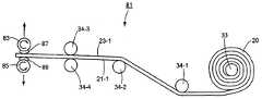
도 3(a)는 도 2에서 도시한 막/지지체 복합체의 박리를 위한 장치의 제 1 구현예의 모식적 측면도이다 (막/지지체 복합체는 반드시 일정한 척도로 그려질 필요가 없음).
도 3(b)는 도 2에서 도시한 막/지지체 복합체의 박리를 위한 장치의 제 2 구현예의 모식적 측면도이다 (막/지지체 복합체는 반드시 일정한 척도로 그려질 필요가 없음).
도 4는 본 발명의 개시내용에 따른 여과막의 제조 방법의 제 2 구현예를 도시하는 흐름도이다.
도 5는 건조 단계 후 및 권취 및 박리 단계 전에 얻어지는 것으로서 도 4의 방법에 따라 형성된 막/지지체 복합체의 간략한 단면도이다 (막/지지체 복합체는 반드시 일정한 척도로 그려질 필요가 없음).
도 6(a) 및 도 6(b)는 도 1 및 도 4의 방법에서 사용될 수 있는 다공성 지지체의 다른 구현예의 평면도 및 단면도이다 (도 6(a) 및 도 6(b)의 다공성 지지체는 반드시 일정한 척도로 그려질 필요가 없음).
도 7은 도 6(a) 및 도 6(b)의 다공성 지지체를 이용하여 형성된 막/지지체 복합체의 제 1 구현예의 단면도이다 (도 7의 다공성 지지체는 반드시 일정한 척도로 그려질 필요가 없음).
도 8은 도 7의 막/지지체 복합체로부터 박리된 막의 측면도이다 (상기 박리된 막은 반드시 일정한 척도로 그려질 필요가 없음).
도 9는 도 6(a) 및 도 6(b)의 다공성 지지체를 이용하여 형성된 막/지지체 복합체의 제 2 구현예의 단면도이다 (도 9의 다공성 지지체는 반드시 일정한 척도로 그려질 필요가 없음).
도 10은 도 9의 막/지지체 복합체로부터 박리한 막의 측면도이다 (상기 박리된 막은 반드시 일정한 척도로 그려질 필요가 없음).The accompanying drawings, which are incorporated in and constitute a part of this specification, are used to illustrate various embodiments of the invention and to explain the principles of the invention in conjunction with the description. In the drawings, like reference numerals designate like parts.
1 is a flow diagram illustrating a first embodiment of a method of making a filtration membrane in accordance with the present disclosure.
FIG. 2 is a schematic cross-sectional view of a membrane / support composite formed according to the method of FIG. 1 as obtained after the drying step and before the winding and peeling steps (the membrane / support composite need not necessarily be drawn to scale).
3 (a) is a schematic side view of a first embodiment of the device for exfoliation of the membrane / support composite shown in FIG. 2 (the membrane / support composite need not necessarily be drawn to scale).
FIG. 3 (b) is a schematic side view of a second embodiment of the device for exfoliation of the membrane / support composite shown in FIG. 2 (the membrane / support composite need not necessarily be drawn to scale).
4 is a flow diagram illustrating a second embodiment of a method of making a filtration membrane in accordance with the present disclosure.
5 is a simplified cross-sectional view of the membrane / support composite formed according to the method of FIG. 4 as obtained after the drying step and before the winding and peeling steps (the membrane / support composite need not necessarily be drawn to scale).
6 (a) and 6 (b) are plan and cross-sectional views of another embodiment of a porous support that can be used in the method of FIGS. 1 and 4 (the porous support of FIGS. 6 (a) and 6 (b) must be Need not be drawn to scale).
FIG. 7 is a cross-sectional view of the first embodiment of the membrane / support composite formed using the porous supports of FIGS. 6 (a) and 6 (b) (the porous supports of FIG. 7 need not necessarily be drawn to scale).
FIG. 8 is a side view of a film peeled from the film / support composite of FIG. 7 (the peeled film need not necessarily be drawn to scale).
FIG. 9 is a cross-sectional view of a second embodiment of the membrane / support composite formed using the porous supports of FIGS. 6 (a) and 6 (b) (the porous supports of FIG. 9 need not necessarily be drawn to scale).
FIG. 10 is a side view of a film peeled from the film / support composite of FIG. 9 (the peeled film need not necessarily be drawn to scale).
도 1을 참조하면, 본 발명의 개시내용에 따라 여과막을 제조하기 위한 방법의 제 1 구현예를 모식적으로 도시하는 흐름도인데, 상기 방법은 도면부호 11로 표시하였다. 본 발명의 이해에 필수적이지는 않지만 당업자에게 알려져 있는 방법(11)의 특정 단계들은 본 발명에서 개시하지 않기로 한다.Referring to FIG. 1, there is a flowchart schematically illustrating a first embodiment of a method for producing a filtration membrane in accordance with the present disclosure, which is indicated by
도시된 바와 같이, 제 1 구현예에 따른 제조방법(11)은 다공성 지지체를 준비하는 단계(13)에서 시작할 수 있다. 일 구현예에 따르면, 상기 다공성 지지체는 직물 또는 부직포일 수 있다. 상기 직물 또는 부직포는 폴리에틸렌 테레프탈레이트(PET), 폴리프로필렌, 나일론(폴리아미드) 및 셀룰로오스계 물질, 예를 들어 셀룰로오스 아세테이트 또는 레이온과 같은 섬유 물질로부터 통상의 방식으로 제조할 수 있으나, 이에 제한되지 않는다. 상기 직물 또는 부직포의 두께는 바람직하게는 50 내지 200㎛, 더욱 바람직하게는 70 내지 150㎛이고, 아주 더 바람직하게는 80 내지 130㎛이다.As shown, the
제 1 구현예에 따른 제조방법(11)의 다음 단계는 상기 다공성 지지체의 상부 표면상에 중합체 용액을 캐스팅하는 단계(15)이다. 상기 중합체 용액의 중합체는 한외여과 또는 정밀여과막의 제조에 적당한 어느 한 종 이상의 중합체를 포함할 수 있는데, 이러한 중합체로는 폴리설폰, 폴리에테르 설폰, 폴리이미드, 폴리아미드, 폴리프로필렌, 및 다양한 할로겐화 중합체, 예를 들어, 폴리비닐리덴 플루오라이드 등이 있으나, 이에 제한되지 않는다. 상기 중합체 용액의 용매는 단일 용매 또는 용매들의 혼합 용매일 수 있다. 사용되는 중합체의 형태, 중합체의 농도 및 용매의 종류는 제조하고자 하는 막이 정밀여과막인지 한외여과막인지에 따라 적절하게 선택될 수 있다.The next step of the
하기에서 명백하게 되는 바와 같이, 상기 중합체 용액은 패브릭 지지체의 제한된 정도의 두께까지만 패브릭 지지체에 침투하는 것이 바람직하다. 더욱 구체적으로, 상기 패브릭 지지체가 90㎛ 미만의 두께를 갖는 경우, 상기 중합체 용액은 패브릭 지지체의 두께의 1/4을 넘지 않는 깊이까지 침투하는 것이 바람직하고, 상기 직물 지지체가 90㎛ 이상의 두께를 갖는 경우, 상기 중합체 용액은 약 25-30㎛의 깊이를 넘지 않는 두께까지 침투하는 것이 바람직하다.As will be apparent below, the polymer solution preferably penetrates into the fabric support only to a limited degree of thickness of the fabric support. More specifically, when the fabric support has a thickness of less than 90 μm, the polymer solution preferably penetrates to a depth not exceeding 1/4 of the thickness of the fabric support, and the fabric support has a thickness of 90 μm or more. In this case, the polymer solution preferably penetrates to a thickness not exceeding a depth of about 25-30 μm.
중합체 용액이 패브릭 지지체에 침투하는 정도는 원칙적으로 중합체 용액의 점도 및 패브릭의 공기 투과도에 의존한다. 일반적으로 말해서, 상기 중합체 용액의 점도는 약 400 내지 10,000cP(centipoise)에 걸쳐서 변화할 수 있다. 상기 용액이 패브릭 내로 너무 깊이 침투하지 않도록 하기 위해서는, 상기 중합체 용액의 점도가 비교적 낮으면 상기 패브릭의 공기 투과도가 비교적 낮게 조절되어야 하고, 상기 중합체 용액의 점도가 비교적 높으면 상기 패브릭의 공기 투과도도 비교적 높게 조절되어야 한다. 예를 들어, 점도가 900cP인 중합체 용액은 공기 투과도가 0.73 cm3/cm2·s인 패브릭에 너무 깊이 침투하지 않고 캐스팅될 수 있으며, 점도가 3,000cP인 중합체 용액은 공기 투과율이 7.5cm3/cm2·s인 패브릭에 너무 깊이 침투하지 않고 캐스팅될 수 있다.The extent to which the polymer solution penetrates into the fabric support depends in principle on the viscosity of the polymer solution and the air permeability of the fabric. Generally speaking, the viscosity of the polymer solution can vary over about 400 to 10,000 cP (centipoise). In order to prevent the solution from penetrating too deeply into the fabric, if the viscosity of the polymer solution is relatively low, the air permeability of the fabric should be controlled relatively low, and if the viscosity of the polymer solution is relatively high, the air permeability of the fabric is also relatively high. It must be adjusted. For example, a polymer solution with a viscosity of 900 cP can be cast without penetrating too deeply into a fabric having an air permeability of 0.73 cm3 / cm2 · s, and a polymer solution with a viscosity of 3,000 cP has an air permeability of 7.5 cm3 / It can be cast without penetrating too deep into the fabric that is cm2 · s.
상기 다공성 지지체에 중합체 용액을 캐스팅하기 위해 사용되는 방법은 통상적일 수 있다.The method used to cast the polymer solution to the porous support may be conventional.
제 1 구현예에 따른 제조방법(11)의 다음 단계는 상기 코팅된 지지체를 수조에서 퀀칭(quenching)하는 단계(17)로서, 상기 퀀칭 결과 상기 패브릭 지지체에 단단히 결합된 막이 형성된다. 상기 코팅된 지지체를 수조에서 퀀칭하는 방법은 통상적일 수 있다. 전술한 바와 같이, 용액내 중합체의 형태, 용액내 중합체의 농도 및 용액내 용매의 종류에 따라, 상기 패브릭 지지체 상에 형성되는 막은 정밀여과막 또는 한외여과막일 수 있다.The next step of the
제 1 구현예에 따른 제조방법(11)의 다음 단계는 상기 막/지지체 복합체를 글리세롤의 약 10% 수용액에 침적시키는 단계(18)이다. 상기 막/지지체를 침적시키는 단계는 통상적일 수 있다.The next step of the
제 1 구현예에 따른 제조방법(11)의 다음 단계는 상기 막/지지체 복합체를 건조시키는 단계(19)이다.The next step of the
도 2를 참조하면, 건조 단계(19)후에 형성되는 막/지지체 복합체의 모식적 단면도가 도시되어 있는데, 상기 막/지지체 복합체는 도면부호 20으로 표시되어 있다. 도시된 바와 같이, 막/지지체 복합체(20)는 다공성 지지체(21) 및 막(23)을 포함한다. 두께가 약 20 내지 60㎛인 막(23)은 전술한 정도의 깊이까지 영역(25)에서 다공성 지지체(21)로 침투되는 것이 바람직한데, 그 침투의 결과, 막(23)은 다공성 지지체(21)에 결합된다.Referring to FIG. 2, there is shown a schematic cross-sectional view of a membrane / support composite formed after the drying
다시 도 1을 참조하면, 본 발명의 여과막의 제조방법(11)의 다음 단계는 상기 막/지지체 복합체를 롤 형태로 권취하는 단계(27)이다. 상기 막/지지체 복합체(20)를 롤 형태로 권취하는 방법은 통상적일 수 있다. 다공성 지지체(21)에 의해 복합체(20)에 제공된 인장 강도 때문에, 권취 단계(27)는 다공성 지지체(21)가 없을 때 가능한 것보다 더욱 높은 장력 및 높은 속도로 수행될 수 있다.Referring back to FIG. 1, the next step in the
제 1 구현예에 따른 제조방법(11)의 다음 단계는 막/지지체 복합체(20)를 박리시키는 단계(29)이다. 도 3(a)를 참조하면, 막/지지체 복합체(20)를 박리하기 위한 장치의 제 1 구현예가 모식적으로 도시되어 있는데, 상기 박리장치는 도면부호 31로 표시되어 있다. 도시된 바와 같이, 장치(31)는 막/지지체 복합체(20)가 롤 형태로 장착되는 권출기(unwinder; 33)를 포함할 수 있다. 또한, 상기 장치(31)는 권출기(33)로부터 원하는 경로로 막/지지체 복합체(20)를 안내하기 위해 사용될 수 있는 복수의 가이드 롤러(34-1, 34-2, 34-3 및 34-4)를 포함할 수 있다. 또한, 상기 장치(31)는 한 쌍의 회전가능하게 구동하는 권취기(37 및 39)를 포함할 수 있는데, 하나의 권취기(37)는 두개의 롤러(34-3 및 34-4) 에 의하여 형성되는 공간의 위에 위치하고, 다른 하나의 권취기(39)는 두개의 롤러(34-3 및 34-4) 에 의하여 형성되는 공간의 아래에 위치한다. 제 1 양면 접착 테이프(41)는 제 1 단부(41-1)가 그 상부면(41-2)을 통해 권취기(37)에 고정되고, 제 2 단부(41-3)이 그 하부면(41-4)을 통해 막(23)의 선단부에 막의 선단면(23-1)을 따라 고정된다. 제 2 양면 접착 테이프(43)는 제 1 단부(43-1)가 그 하부면(43-2)을 통해 권취기(39)에 고정되고 제 2 단부(43-3)가 그 상부면(43-4)을 통해 지지체(21)의 선단부에 지지체의 하부면(21-1)을 따라 고정된다. 접착 테이프(41 및 43)는 본질적으로 통상적일 수 있고, 충분히 접착성이 있어서, 권취기(37 및 39)가 도시된 형태로 회전함에 따라, 막(23)이 지지체(21)로부터 박리되어, 막(23)은 권취기(37)에 롤 형태로 권취되고, 지지체(21)는 권취기(39)에 롤 형태로 권취된다. 접착 테이프(41 및 43)는 지지체(21) 및 막(23)만큼 넓을 수 있으나, 반드시 그럴 필요는 없다.The next step of the
사용시, 막/지지체 복합체(20)의 선단부는 권출기(33)로부터 권출된 다음, 가이드 롤러(34-1 및 34-2)를 가로질러 인출되어, 가이드 롤러(34-3 및 34-4) 사이로 인출될 수 있다. 접착 테이프(41 및 43)는 권취기(37 및 39)로부터 각각 부분적으로 권출된 다음, 테이프(41)의 제 2 단부(41-3)가 막(23)의 상부 표면(23-1)애 고정되고, 테이프(43)의 제 2 단부(43-3)가 지지체(21)의 하부 표면에 고정될 수 있다. 다음에, 권취기(37 및 39)는 처음에는 막(23)이 권취기(37)에 서서히 권취되기 시작한 다음 빠르게 권취됨에 따라 도 3(a)에서 도시한 바와 같이 회전할 수 있다. (필요한 경우, 테이프(41)의 제 2 단부(41-3)를 막(23)의 상부 표면에 부착하기 전 및 테이프(43)의 제 2 단부(43-3)를 지지체(21)의 하부 표면(21-1)에 부착하기 전에, 전술한 바와 같이 테이프의 도움을 받는 박리가 용이하게 되도록 하기 위하여 막(23) 및 지지체(21)의 각각의 선단부를 수동으로 박리시킬 수 있다).In use, the leading end of the membrane /
전술한 형태로 장치(31)를 이용하는 최종 결과는 테이프(41) 및 막(23)이 권취기(37)에 롤 형태로 순차적으로 권취되고 테이프(43) 및 지지체(21)가 권취기(39)에 롤 형태로 순차적으로 권취된다는 것이다. 쉽게 알 수 있는 바와 같이, 막(23)이 지지체(21)내로 깊이 침투하는 경우, 전술한 방식으로 지지체(21)로부터 막(23)을 박리하는 것은 막(23)에 원하지 않는 손상을 초래할 수 있다..The final result of using the
이와 같이 권출기(37)에 롤 형태로 권취된 막(23)의 경우, 막(23)은 통상적인 방식 또는 다른 방식으로 다양한 최종제품의 구조들 중 어느 하나로 후가공될 수 있는데, 이러한 구조로는 절곡형 카트리지, 나선형으로 권취된 막 및 평판형 막이 있으나, 이에 제한되지 않는다. 이러한 구조체의 막은 지지체가 없기 때문에, 이는 예를 들어 절곡형 카트리지로 쉽게 접힐 수 있고, 얻어지는 최종제품의 구조는 대표적으로, 지지체가 존재하는 경우에 가능하게 되는 것보다 더욱 큰 표면적을 갖는다. 이러한 표면적의 증가는 아주 바람직한 것이다.In the case of the
막/지지체 복합체(20)를 박리시키기 위한 간략한 장치의 제 2 구현예가 도 3(b)에서 도시되어 있는데, 상기 장치는 도면부호 81로 표시되어 있다. 장치(81)는 장치(31)와 대부분의 점에서 유사한데, 두 장치 사이의 주요한 차이는 장치(31)는 한 쌍의 권취기(37 및 39) 및 한 쌍의 양면 접착 테이프(41 및 43)을 포함하는 반면에, 장치(81)는 한 쌍의 권취기(83 및 85) 및 한 쌍의 양면 접착 테이프(87 및 89)를 포함한다. 테이프(87)는 권취기(83)에 막(23)의 상부 표면(23-1)을 부착하기 위해 사용되고, 테이프(89)는 권취기(85)에 지지체(21)의 하부표면(21-1)을 부착하기 위해 사용된다. 권취기(83 및 85)는 도시한 방향으로 회전가능한 외에도, 도시한 방향으로 동시에 함께 이동할 수 있다. 이런 방식으로, 권취기(83 및 85)가 서로 이격되게 함께 이동하고 회전함에 따라, 막(23)과 지지체(21)는 서로로부터 박리되면서, 막(23)은 권취기(83)에 롤 형태로 권취되고 지지체(21)는 권취기(85)에 롤 형태로 권취된다. 도시된 바와 같이, 권취기(83 및 85)는 처음에는 서로 근접하여 위치하므로, 테이프(87 및 89)는 테이프(41 및 43)보다 상당히 짧을 수 있다(필요한 경우, 막(23)의 상부 표면(23-1)에 테이프(87)를 부착하기 전 및 지지체(21)의 하부 표면(21-1)에 테이프(89)를 부착하기 전에, 전술한 테이프의 도움을 받는 박리가 용이하게 되도록 하기 위하여 막(23) 및 지지체(21)의 각각의 선단부를 수동으로 박리시킬 수 있다).A second embodiment of a simplified device for peeling the membrane /
도 4를 참조하면, 본 발명의 개시내용에 따른 여과막의 제조 방법의 제 2 구현예를 개략적으로 나타내는 흐름도가 도시되어 있는데, 상기 방법은 도면부호 111로 표시되었다. 제 2 구현에에 따른 제조방법(111)의 특정 단계들 중에서 본 발명의 이해에 필수적이지는 않으면서 당업자에게 알려져 있는 것들은 본 발명에서 설명하지 않기로 한다.Referring to FIG. 4, there is shown a flow diagram schematically illustrating a second embodiment of a method of making a filtration membrane in accordance with the present disclosure, which is indicated by
제 2 구현예에 따른 제조방법(111)은 제 1 구현예에 따른 제조방법(11)과 많은 점에서 유사한데, 두 방법들 사이의 주요한 차이는 제 2 구현예에 따른 방법(111)이 막(23)(바람직하게는 한외여과막 형태의 막(23))의 노출 표면 상에 폴리아미드 층을 형성하는 단계(113)를 추가로 포함하여 지지체(21) 상에 2층 또는 복합 막을 형성한다는 것이다. 전술한 폴리아미드 층을 형성하는 방법은 통상적인 것일 수 있고, 예를 들어, 다관능성 아민과 다관능성 아실 할라이드의 계면 중합을 포함할 수 있다.The
도 5는 단계(113) 이후에 형성되는 막/지지체 복합체의 모식적 단면도로서, 상기 막/지지체 복합체는 도면부호 120으로 표시되었다. 도시된 바와 같이, 막/지지체 복합체는 다공성 막(21) 및 복합막(122)을 포함하는데, 상기 복합막(122)은 막(23) 및 폴리아미드 층(124)을 포함한다. 상기 막(23)은 두께가 약 20 내지 60㎛일 수 있으며, 전술한 정도까지 영역(25)에서 다공성 지지체(21)를 침투하는 것이 바람직하고, 이러한 침투의 결과, 막(23)은 다공성 지지체(21)에 결합된다. 두께가 약 0.2 내지 0.6㎛일 수 있는 폴리아미드 층(124)은 막(23)의 상부 표면에 결합된다.FIG. 5 is a schematic cross-sectional view of the membrane / support composite formed after
다시 도 4를 참조하면, 제 2 구현예에 따른 제조방법(111)은 약 3% 글리세롤 수용액에 침적하는 침적 단계(18) 및 건조 단계(19) 이후에 막/지지체 복합체(120)를 롤 형태로 권취하는 단계(127)를 포함할 수 있다. 상기 막/지지체 복합체(120)를 권취하는 방법은 통상적일 수 있다. 단계(127) 이후, 제 2 구현예에 따른 제조방법(111)은 지제체 복합체(21)로부터 복합막(122)을 박리시키는 단계(129)가 계속될 수 있다. 박리 단계(129)는 예를 들어 상기 막/지지체 복합체(20)에 대하여 기재한 것과 유사한 방식으로 장치(31)를 이용하여 수행될 수 있는데, 주요한 차이는 테이프(41)가 막(23)의 상부 표면에 고정되는 것이 아니라 폴리아미드 층(124)의 상부 표면에 고정된다는 것이다. 박리 단계(129)를 수행한 결과, 테이프(41) 및 복합막(122)이 권취기(37)에 순차적으로 권취되고, 테이프(43) 및 지지체(21)가 권취기(39)에 순차적으로 귄취된다.Referring back to FIG. 4, the
이와 같이 권취기(37)에 롤 형태로 권취된 복합막(122)의 경우, 막(122)은 통상적인 방식 또는 다른 방식으로 여러 가지 최종제품의 구조들 중 어느 하나로 후가공될 수 있는데, 이러한 구조로는 절곡형 카트리지, 나선형으로 권취된 막 및 평판형 막이 있으나, 이에 제한되지 않는다. 이러한 최종제품 구조의 막은 지지체를 동반하지 않기 때문에, 이는 예를 들어 절곡형 카트리지로 더욱 용이하게 주름잡힐 수 있고, 얻어지는 최종제품의 구조는 지지체가 존재하는 경우에 가능한 것보다 더욱 큰 표면적을 갖는다. 이러한 증가된 표면적은 아주 바람직한 것이다. 게다가 막에 지지체가 결합되어 있지 않기 때문에, 그 막은 그 막에 통상적으로 결합된 패브릭 지지체가 물 흐름에 바람직하지 못한 저항을 주게 되는 정삼투와 같은 용도로 유용할 수 있다.In the case of the
쉽게 알 수 있는 바와 같이, 장치(31)를 이용하여 박리 단계(129)를 수행하는 대신에, 장치(81)가 이용될 수 있다.As can be readily appreciated, instead of performing the
도 6(a) 및 도 6(b)를 참조하면, 제 1 구현예에 따른 제조방법(11) 및 제 2 구현예에 따른 제조방법(111)에서 사용될 수 있는 다공성 지지체의 또 다른 구현예의 평면도 및 단면도가 각각 도시되어 있는데, 상기 다공성 지지체는 도면부호 121로 표시되어 있다.6 (a) and 6 (b), plan views of another embodiment of a porous support that can be used in the
다공성 지지체(211)는 시트상의 물체(213)를 포함할 수 있는데, 상기 시트상 물체는 예를 들어 PET 필름, 폴리프로필렌 필름, 폴리에틸렌 필름, 아크릴 필름, 나일론(폴리아미드) 필름, 폴리이미드 필름, 및 폴리카보네이트 필름과 같은 중합체 필름일 수 있다.The
시트상 물체(213)에는, 니들 펀칭 또는 다른 적당한 방법, 예를 들어 레이저 펀칭 또는 전자 펀칭으로 만들어질 수 있는 다수의 횡단 개구부(transverse opening)(215)가 구비될 수 있는데, 상기 개구부(215)는 시트상 물체(213)의 상부 표면(217)로부터 시트상 물체(213)의 하부 표면(219)까지 연장되어 있다. 횡단 개구부(215)가 존재하는 것을 제외하고, 재료(215)는 비다공성일 수 있다. 횡단 개구부(215)는 약 0.01~5mm의 직경을 가질 수 있고, 약 0.05~100mm 정도의 간격으로 서로 이격될 수 있다. 예를 들어, 시트상 물질(213)이 중합체 필름인 경우, 시트상 물체(213)는 두께가 약 0.05~1.0mm일 수 있다.The sheet-
도 7을 참조하면, 방법(11)에서 다공성 지지체(211)를 이용하여 형성될 수 있는 막/지지체 복합체의 일 구현예의 단면도가 도시되어 있는데, 상기 막/지지체 복합체는 도면부호 251로 표시되어 있다.Referring to FIG. 7, there is shown a cross-sectional view of one embodiment of a membrane / support composite that may be formed using
상기 복합체(251)는 지지체(211)를 포함한다. 또한, 복합체(251)는 지지체(211)에 결합된 막(253)을 추가로 포함할 수 있다. 막(253)은 제 1 구현예에 따른 제조방법(11)의 단계(15)에서와 같이 지지체(211)의 상부 표면에 적당한 중합체 용액을 캐스팅한 다음, 제 1 구현예에 따른 제조방법(11)의 단계(17)에서와 같이 상기 코팅된 지지체를 퀀칭하고, 제 1 구현예에 따른 제조방법(11)의 단계(19)에서와 같이 상기 막을 건조시킴으로써 형성될 수 있다. 바람직하게는, 지지체(211)상에 캐스팅된 중합체 용액의 점도 및 개구부(215)의 구멍 직경은, 개구부(215)를 통한 중합체 용액의 흐름이 크지 않아서, 지지체(211)의 전체 상부 표면상에 뿐만 아니라 지지체(211)의 하부 표면상에 막이 과도하게 형성되지 않도록 선택되어야 하는데, 이와 같은 구조는 박리를 상당히 더 어렵게 만들기 때문이다.The composite 251 includes a
장치(31) 또는 장치(81)를 이용하여, 지지체(211)와 막(253)이 서로 박리될 수 있다. 도 8에서 최상으로 볼 수 있는 바와 같이, 박리 공정의 결과, 지지체(211)의 개구부(215) 내에 위치하던 다수의 돌출부(255)를 저면에 구비한 막(253)이 제공된다. 이러한 돌출부(255)의 패턴은 지지체(211) 내의 개구부(215)의 배열에 대응하고, 예를 들어 광학 현미경을 이용하여 관찰할 수 있다.Using the
도 9를 참조하면, 방법(111)에서 다공성 지지체(211)를 이용하여 형성될 수 있는 막/지지체 복합체의 일 구현예의 단면도가 도시되어 있는데, 상기 막/지지체 복합체는 도면부호 351로 표시되어 있다.Referring to FIG. 9, there is shown a cross-sectional view of one embodiment of a membrane / support composite that may be formed using a
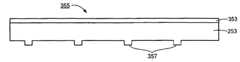
복합체(351)는 복합체(251)와 많은 점에서 유사한데, 두 복합체들 사이의 주요한 차이는 복합체(351)는 예를 들어 제 2 구현예에 따른 제조방법(111)의 단계(113)에 의해 형성될 수 있는 폴리아미드 층(353)을 추가로 포함한다는 것이다. 장치(31) 또는 장치(81)를 이용하여, 복합체(351)는 박리되어 복합막(355)(폴리아미드 층(353) 및 막(253) 포함) 및 지지체가 제조된다. 도 10에서 최상으로 도시한 바와 같이, 막(253)의 저면에 지지체(211)의 개구부(215)내에 위치하였던 복수의 돌출부(357)를 구비한 복합막(355)이 제공된다. 지지체(211) 내의 개구부(215)의 패턴에 상응하고 예를 들어 광학 현미경을 이용하여 관찰될 수 있는 돌출부(357)는 물흐름 채널 및 난류 발생기구로 이용된다는 장점이 있다. 이러한 물리적 특징은 막(355)이 역삼투, 특히 정삼투 및 압력지연 삼투에 사용되는 경우에 아주 바람직한 것이다.The composite 351 is similar in many respects to the composite 251, with the major difference between the two composites being that the composite 351 is for example by
알 수 있는 바와 같이, 본 발명의 개시내용에 따라 다공성 지지체로부터 막을 박리시킨 후, 상기 다공성 지지체는 재순환 및 재이용될 수 있다.
As can be seen, after peeling the membrane from the porous support according to the present disclosure, the porous support can be recycled and reused.
하기의 실시예는 오로지 예시적인 것으로서 어떤 식으로든 본 발명을 제한하지 않는다.
The following examples are illustrative only and do not limit the invention in any way.
[실시예 1]Example 1
점도가 920cP인 디메틸포름아미드(DMF)에 용해시킨 17.6% 폴리설폰 용액을, 160㎛의 갭을 갖는 닥터 나이프를 이용하여 0.73cm3/cm2·s의 공기 투과율을 갖는 부직포(100㎛ 두께) 상에 캐스팅했다. 상기 부직포 상의 중합체 용액을 물에서 퀀칭하였다. 얻어진 막(한외여과막)을 물에 세정하고, 10% 글리세롤에 침적한 다음, 60℃에서 5 분간 건조하였다. 얻어진 복합막의 두께는 약 140㎛였다. 다음으로, 상기 막을 도 3(a)에 도시된 유형의 박리 장치를 이용하여 박리하였다. 이후, 0.1% 폴리에틸렌 옥사이드(분자량 100,000) 수용액의 플럭스 및 제거율(rejection)을, 1 bar (14.5psi)에서 평판형 교차흐름 시험 장치 및 절곡형 모듈 시험장치를 이용하여 측정했다. 상기 투과수 내의 폴리에틸렌 옥사이드(PEO) 함량은 HPLC로 분석했다. 그 결과를 표 1에 정리하였다.A 17.6% polysulfone solution dissolved in dimethylformamide (DMF) having a viscosity of 920 cP was a nonwoven fabric (100 μm thick) having an air permeability of 0.73 cm3 / cm2 · s using a doctor knife having a gap of 160 μm. Cast on The polymer solution on the nonwoven was quenched in water. The obtained membrane (ultrafiltration membrane) was washed with water, immersed in 10% glycerol, and dried at 60 ° C for 5 minutes. The thickness of the obtained composite film was about 140 micrometers. Next, the film was peeled off using a peeling device of the type shown in Fig. 3 (a). The flux and rejection of a 0.1% polyethylene oxide (molecular weight 100,000) aqueous solution were then measured using a flat crossflow test device and a bent module test device at 1 bar (14.5 psi). The polyethylene oxide (PEO) content in the permeate was analyzed by HPLC. The results are summarized in Table 1.
이러한 결과는 PEO 제거율 및 플럭스가 박리로 인해 변화하지 않아서, 박리 공정의 결과로서 막에 대한 손상이 일어나지 않았음을 나타낸다.
These results indicate that the PEO removal rate and flux did not change due to delamination, resulting in no damage to the membrane as a result of the delamination process.
[실시예 2][Example 2]
지지체로서 실시예 1로부터 얻은 상기 복합막을 2중량%의 메타-페닐렌디아민(MPD) 및 0.2% 2-에틸-1,3-헥산디올을 함유하는 수용액에 40 초간 침적했다. 상기 지지체의 물기를 제거하고 및 닙-롤링(nip-rolled)하여 과량의 수용액을 제거했다. 다음으로, 상기 코팅된 지지체를 이소파 용매(Isopar
상기의 결과는 플럭스 및 염제거율이 박리 전후에 변화하지 않아서, 박리 공정 동안 막에 손상이 발생하지 않았다는 것을 나타낸다.
The above results indicate that the flux and salt removal rate did not change before and after exfoliation, so that no damage to the membrane occurred during the exfoliation process.
전술한 본 발명의 실시예들은 오로지 예시적인 것으로서, 당업자라면 본 발명의 범위를 벗어나지 않고 상기 실시예에 대한 여러 가지 변화 및 변형을 이룰 수 있을 것이다. 모든 이러한 변화 및 변형은 특허청구범위에서 정의한 본 발명의 범위에 포함되는 것으로 해석된다.The embodiments of the present invention described above are exemplary only, and those skilled in the art can make various changes and modifications to the embodiments without departing from the scope of the present invention. All such changes and modifications are intended to be included within the scope of this invention as defined in the claims.
Claims (50)
Translated fromKorean(b) 상기 다공성 지지체 상에 중합체 용액을 캐스팅하여 코팅된 지지체를 형성하는 단계와,
(c) 상기 코팅된 지지체를 퀀칭하여 막/지지체 복합체를 형성하는 단계와,
(d) 상기 막/지지체 복합체를 건조하는 단계와,
(e) 상기 막/지지체 복합체를 박리시켜 지지되지 않은 여과막을 형성하는 단계를 포함하는 여과막의 제조 방법.(a) preparing a porous support;
(b) casting a polymer solution on the porous support to form a coated support;
(c) quenching the coated support to form a membrane / support complex;
(d) drying the membrane / support composite,
(e) peeling the membrane / support composite to form an unsupported filtration membrane.
상기 막/지지체 복합체는 막 측 및 지지체 측을 갖고,
상기 박리 단계는 상기 막/지지체 복합체의 막 측에 제 1 접착 테이프를 고정하고, 상기 막/지지체 복합체의 지지체 측에 제 2 접착 테이프를 고정한 다음, 상기 제 1 및 제 2 접착 테이프를 당겨 떼어내어 상기 막/지지체 복합체의 지지체 측으로부터 막/지지체 복합체의 막측을 분리하여 수행되는 것을 특징으로 하는 여과막의 제조방법.The method of claim 1,
The membrane / support composite has a membrane side and a support side,
In the peeling step, the first adhesive tape is fixed on the membrane side of the membrane / support composite, the second adhesive tape is fixed on the support side of the membrane / support composite, and then the first and second adhesive tapes are pulled off. Method for producing a filtration membrane, characterized in that carried out by separating the membrane side of the membrane / support complex from the support side of the membrane / support complex.
상기 제 1 접착 테이프는 제 1 단부 및 제 2 단부를 갖고, 상기 제 2 접착 테이프는 제 1 단부 및 제 2 단부를 갖고,
상기 제 1 접착 테이프의 제 1 단부는 상기 막/지지체 복합체의 막 측에 고정되고, 상기 제 1 접착 테이프의 제 2 단부는 제 1의 회전식 권취기에 도포되고,
상기 제 2 접착 테이프의 제 1 단부는 상기 막/지지체 복합체의 지지체 측에 고정되고, 상기 제 2 접착 테이프의 제 2 단부는 제 2의 회전식 권취기에 고정되고,
상기 당김은 상기 제 1 및 제 2 회전식 권취기를 적절히 회전시켜서 달성되는 것을 특징으로 하는 여과막의 제조방법.3. The method of claim 2,
The first adhesive tape has a first end and a second end, the second adhesive tape has a first end and a second end,
A first end of the first adhesive tape is fixed to the membrane side of the membrane / support composite, a second end of the first adhesive tape is applied to a first rotary winder,
A first end of the second adhesive tape is fixed to the support side of the membrane / support composite, a second end of the second adhesive tape is fixed to a second rotary winding machine,
And said pulling is accomplished by appropriately rotating said first and second rotary winding machines.
(b) 상기 다공성 지지체 상에 중합체 용액을 캐스팅하여 코팅된 지지체를 형성하는 단계와,
(c) 상기 코팅된 지지체를 퀀칭하여 막/지지체 복합체를 형성하는 단계와,
(d) 상기 막/지지체 복합체 상에 폴리아미드 층을 형성하여 다층의 막/지지체 복합체를 형성하는 단계와,
(e) 상기 다층 막/지지체 복합체를 건조하는 단계와,
(f) 상기 다층 막/지지체 복합체를 박리시켜 지지되지 않은 다층 여과막을 형성하는 단계를 포함하는 여과막의 제조 방법.(a) preparing a porous support;
(b) casting a polymer solution on the porous support to form a coated support;
(c) quenching the coated support to form a membrane / support complex;
(d) forming a polyamide layer on the membrane / support composite to form a multilayer membrane / support composite,
(e) drying the multilayer membrane / support composite,
(f) peeling off the multilayer membrane / support composite to form an unsupported multilayer filtration membrane.
상기 막/지지체 복합체는 막 측 및 지지체 측을 갖고,
상기 박리 단계는 상기 막/지지체 복합체의 막 측에 제 1 접착 테이프를 고정하고, 상기 막/지지체 복합체의 지지체 측에 제 2 접착 테이프를 고정한 다음, 상기 제 1 및 제 2 접착 테이프를 당겨 상기 막/지지체 복합체의 지지체 측으로부터 막/지지체 복합체의 막측을 분리하여 수행되는 것을 특징으로 하는
여과막의 제조방법.27. The method of claim 26,
The membrane / support composite has a membrane side and a support side,
In the peeling step, the first adhesive tape is fixed to the membrane side of the membrane / support composite, the second adhesive tape is fixed to the support side of the membrane / support composite, and then the first and second adhesive tapes are pulled to form the membrane. / Separating the membrane side of the membrane / support complex from the support side of the support complex
Method for producing a filtration membrane.
상기 제 1 접착 테이프는 제 1 단부 및 제 2 단부를 갖고, 상기 제 2 접착 테이프는 제 1 단부 및 제 2 단부를 갖고,
상기 제 1 접착 테이프의 제 1 단부는 상기 막/지지체 복합체의 막 측에 고정되고, 상기 제 1 접착 테이프의 제 2 단부는 제 1의 회전식 권취기에 고정되고,
상기 제 2 접착 테이프의 제 1 단부는 상기 막/지지체 복합체의 지지체 측에 고정되고, 상기 제 2 접착 테이프의 제 2 단부는 제 2의 회전식 권취기에 고정되고,
상기 당김은 상기 제 1 및 제 2 회전식 권취기를 적절히 회전시켜서 달성되는 것을 특징으로 하는
여과막의 제조방법.28. The method of claim 27,
The first adhesive tape has a first end and a second end, the second adhesive tape has a first end and a second end,
A first end of the first adhesive tape is fixed to the membrane side of the membrane / support composite, a second end of the first adhesive tape is fixed to a first rotary winder,
A first end of the second adhesive tape is fixed to the support side of the membrane / support composite, a second end of the second adhesive tape is fixed to a second rotary winding machine,
Said pulling is achieved by appropriately rotating said first and second rotary winders
Method for producing a filtration membrane.
(b) 상기 다공성 지지체 상에 여과막을 형성하여, 막/지지체 복합체를 형성하는 단계와,
(c) 상기 막/지지체 복합체를 박리시켜 지지되지 않은 여과막 및 재생된 다공성 지지체를 제작하는 단계와,
(d) 상기 재생된 다공성 지지체를 이용하여 상기 단계 (b) 및 (c)를 적어도 한 번 반복하는 단계를 포함하는 복수개의 여과막을 제조하는 방법.(a) preparing a porous support,
(b) forming a filtration membrane on the porous support to form a membrane / support composite;
(c) peeling the membrane / support composite to produce an unsupported filtration membrane and a regenerated porous support,
(d) repeating steps (b) and (c) at least once using the regenerated porous support.
Applications Claiming Priority (2)
| Application Number | Priority Date | Filing Date | Title |
|---|---|---|---|
| US12/931,304US8820540B2 (en) | 2011-01-28 | 2011-01-28 | Method for preparing a filtration membrane and filtration membrane prepared by said method |
| US12/931,304 | 2011-01-28 |
Publications (2)
| Publication Number | Publication Date |
|---|---|
| KR20120099564A KR20120099564A (en) | 2012-09-11 |
| KR101359956B1true KR101359956B1 (en) | 2014-02-13 |
Family
ID=46576466
Family Applications (1)
| Application Number | Title | Priority Date | Filing Date |
|---|---|---|---|
| KR1020110098408AActiveKR101359956B1 (en) | 2011-01-28 | 2011-09-28 | Method for preparing a filtration membrane and filtration membrane prepared by said method |
Country Status (2)
| Country | Link |
|---|---|
| US (1) | US8820540B2 (en) |
| KR (1) | KR101359956B1 (en) |
Cited By (1)
| Publication number | Priority date | Publication date | Assignee | Title |
|---|---|---|---|---|
| KR101601611B1 (en)* | 2015-10-02 | 2016-03-08 | 손재무 | Equipment for producing recycling aggrete using waste concrete |
Families Citing this family (18)
| Publication number | Priority date | Publication date | Assignee | Title |
|---|---|---|---|---|
| US8820540B2 (en)* | 2011-01-28 | 2014-09-02 | Woongjin Chemical Co., Ltd. | Method for preparing a filtration membrane and filtration membrane prepared by said method |
| US9382381B2 (en)* | 2012-06-29 | 2016-07-05 | Nissan Chemical Industries, Ltd. | Aromatic polyamide and film-forming composition containing same |
| CN103933868A (en)* | 2013-01-17 | 2014-07-23 | 华东理工大学 | Preparation method of methanol-water ceramic-based hollow-fiber-penetrated vaporized composite membrane |
| CN103537200B (en)* | 2013-10-25 | 2016-06-22 | 华南理工大学 | A kind of Cellulose acetate forward osmotic membrane and preparation method thereof |
| CN103599704B (en)* | 2013-11-08 | 2016-05-04 | 江南大学 | A kind of method without the finishing of supporter porous diffusion barrier anionic that UV solidifies |
| CN103599703B (en)* | 2013-11-08 | 2016-05-04 | 江南大学 | A kind of method without the finishing of supporter porous polymeric membrane for separation nonionic that UV solidifies |
| CN103611424B (en)* | 2013-11-08 | 2016-06-01 | 江南大学 | A kind of method without supporter porousness polymeric membrane for separation anionic finishing of thermofixation |
| CN103657429B (en)* | 2013-11-08 | 2016-05-04 | 江南大学 | A kind of method without the cationic finishing of supporter porous polymeric membrane for separation of heat cure |
| CN103657438B (en)* | 2013-11-08 | 2016-06-01 | 江南大学 | A kind of method without supporter porousness polymeric membrane for separation non-ionic type finishing of thermofixation |
| US20150165388A1 (en)* | 2013-12-17 | 2015-06-18 | Pall Corporation | Skinless polyethersulfone membrane |
| US10532322B2 (en)* | 2014-07-17 | 2020-01-14 | The Research Foundation For The State University Of New York | Elastic membrane-based membrane bioreactor with high-efficiency for fouling control |
| CN104258745A (en)* | 2014-10-24 | 2015-01-07 | 南京水思环保科技有限公司 | Preparation method of hydrophilic polyethersulfone microfiltration membrane |
| CN105597570A (en)* | 2016-02-26 | 2016-05-25 | 天津大学 | Preparation method of attapulgite/polyamide hybrid nanofiltration membrane |
| CN105617885A (en)* | 2016-03-25 | 2016-06-01 | 北京碧水源膜科技有限公司 | Device and method for continuously preparing forward osmosis composite membrane |
| US11701623B2 (en) | 2020-05-15 | 2023-07-18 | Entegris, Inc. | Method of forming a laminated single layer composite membrane |
| CN112316737B (en)* | 2020-09-30 | 2022-09-02 | 天津工业大学 | Separation membrane support and preparation method thereof |
| WO2023135452A1 (en)* | 2022-01-17 | 2023-07-20 | Arun Ganesaraman | An apparatus and a method for wastewater treatment |
| KR20240049464A (en) | 2022-10-08 | 2024-04-16 | 김주형 | Diagonal Mounted Case |
Citations (3)
| Publication number | Priority date | Publication date | Assignee | Title |
|---|---|---|---|---|
| EP1060007B1 (en) | 1998-03-05 | 2003-07-09 | Cuno Incorporated | Reinforced microporous filtration membrane and process of making and using same |
| KR100874079B1 (en) | 2001-02-16 | 2008-12-12 | 도레이 카부시키가이샤 | Separator, Separator Member, Separator Module, Sewage Treatment System and Manufacturing Method of Separator |
| JP2010017714A (en) | 2005-03-30 | 2010-01-28 | Saehan Industries Inc | Composite polyamide reverse osmosis membrane and method of producing the same |
Family Cites Families (16)
| Publication number | Priority date | Publication date | Assignee | Title |
|---|---|---|---|---|
| GB1391973A (en) | 1971-09-07 | 1975-04-23 | Aqua Chem Inc | Polyvinyl acetal membrane |
| US4277344A (en) | 1979-02-22 | 1981-07-07 | Filmtec Corporation | Interfacially synthesized reverse osmosis membrane |
| US4629563B1 (en) | 1980-03-14 | 1997-06-03 | Memtec North America | Asymmetric membranes |
| US4830885A (en) | 1987-06-08 | 1989-05-16 | Allied-Signal Inc. | Chlorine-resistant semipermeable membranes |
| US4872984A (en) | 1988-09-28 | 1989-10-10 | Hydranautics Corporation | Interfacially synthesized reverse osmosis membrane containing an amine salt and processes for preparing the same |
| US4950404A (en) | 1989-08-30 | 1990-08-21 | Allied-Signal Inc. | High flux semipermeable membranes |
| US4983291A (en) | 1989-12-14 | 1991-01-08 | Allied-Signal Inc. | Dry high flux semipermeable membranes |
| JP3006976B2 (en) | 1993-06-24 | 2000-02-07 | 日東電工株式会社 | Method for producing highly permeable composite reverse osmosis membrane |
| US5614099A (en) | 1994-12-22 | 1997-03-25 | Nitto Denko Corporation | Highly permeable composite reverse osmosis membrane, method of producing the same, and method of using the same |
| US5886059A (en) | 1997-07-08 | 1999-03-23 | Memtec America Corporation | Highly asymmetric polyethersulfone filtration membranes |
| US6015495A (en) | 1998-02-18 | 2000-01-18 | Saehan Industries Incorporation | Composite polyamide reverse osmosis membrane and method of producing the same |
| US6063278A (en) | 1998-04-28 | 2000-05-16 | Saehan Industries Inc. | Composite polyamide reverse osmosis membrane and method of producing the same |
| US6245234B1 (en) | 1999-06-03 | 2001-06-12 | Saehan Industries Incorporation | Composite polyamide reverse osmosis membrane and method of producing the same |
| US7229665B2 (en)* | 2001-05-22 | 2007-06-12 | Millipore Corporation | Process of forming multilayered structures |
| AU2010289795B2 (en)* | 2009-08-24 | 2015-09-24 | Oasys Water LLC | Forward osmosis membranes |
| US8820540B2 (en)* | 2011-01-28 | 2014-09-02 | Woongjin Chemical Co., Ltd. | Method for preparing a filtration membrane and filtration membrane prepared by said method |
- 2011
- 2011-01-28USUS12/931,304patent/US8820540B2/enactiveActive
- 2011-09-28KRKR1020110098408Apatent/KR101359956B1/enactiveActive
Patent Citations (3)
| Publication number | Priority date | Publication date | Assignee | Title |
|---|---|---|---|---|
| EP1060007B1 (en) | 1998-03-05 | 2003-07-09 | Cuno Incorporated | Reinforced microporous filtration membrane and process of making and using same |
| KR100874079B1 (en) | 2001-02-16 | 2008-12-12 | 도레이 카부시키가이샤 | Separator, Separator Member, Separator Module, Sewage Treatment System and Manufacturing Method of Separator |
| JP2010017714A (en) | 2005-03-30 | 2010-01-28 | Saehan Industries Inc | Composite polyamide reverse osmosis membrane and method of producing the same |
Cited By (1)
| Publication number | Priority date | Publication date | Assignee | Title |
|---|---|---|---|---|
| KR101601611B1 (en)* | 2015-10-02 | 2016-03-08 | 손재무 | Equipment for producing recycling aggrete using waste concrete |
Also Published As
| Publication number | Publication date |
|---|---|
| KR20120099564A (en) | 2012-09-11 |
| US20120193284A1 (en) | 2012-08-02 |
| US8820540B2 (en) | 2014-09-02 |
Similar Documents
| Publication | Publication Date | Title |
|---|---|---|
| KR101359956B1 (en) | Method for preparing a filtration membrane and filtration membrane prepared by said method | |
| CN102574071B (en) | Forward osmosis membranes | |
| JP4484635B2 (en) | Spiral type reverse osmosis membrane element and manufacturing method thereof | |
| US10010833B2 (en) | Spiral wound membrane module with reinforced fold line | |
| JP2003245530A (en) | Separation membrane | |
| KR20200076283A (en) | reverse osmosis membrane and manufacturing method thereof | |
| JP3681219B2 (en) | Polysulfone porous separation membrane | |
| JP7403524B2 (en) | Composite hollow fiber membrane and method for manufacturing composite hollow fiber membrane | |
| JPS5814904A (en) | Support sheet for liquid separation membrane and continuous preparation thereof | |
| JP7075887B2 (en) | Filter element and its manufacturing method | |
| WO2015147750A1 (en) | Highly permeable double-skinned forward osmosis membrane for anti-fouling in the emulsified oil-water separation process | |
| KR20180097700A (en) | METHOD FOR PRODUCING FILM AND RELATED FILM AND FILTER ELEMENT | |
| JP3105610B2 (en) | Spiral type membrane separation module and its cleaning method. | |
| AU2015227384A1 (en) | Forward osmosis membranes | |
| JP2020131158A (en) | Separation membrane element and method of use thereof | |
| KR20180050166A (en) | Method for manufacturing water-treatment membrane, water-treatment membrane manufactured by thereof, and water treatment module comprising membrane |
Legal Events
| Date | Code | Title | Description |
|---|---|---|---|
| A201 | Request for examination | ||
| PA0109 | Patent application | Patent event code:PA01091R01D Comment text:Patent Application Patent event date:20110928 | |
| PA0201 | Request for examination | ||
| PG1501 | Laying open of application | ||
| E902 | Notification of reason for refusal | ||
| PE0902 | Notice of grounds for rejection | Comment text:Notification of reason for refusal Patent event date:20121116 Patent event code:PE09021S01D | |
| E902 | Notification of reason for refusal | ||
| PE0902 | Notice of grounds for rejection | Comment text:Notification of reason for refusal Patent event date:20130328 Patent event code:PE09021S01D | |
| E701 | Decision to grant or registration of patent right | ||
| PE0701 | Decision of registration | Patent event code:PE07011S01D Comment text:Decision to Grant Registration Patent event date:20131030 | |
| GRNT | Written decision to grant | ||
| PR0701 | Registration of establishment | Comment text:Registration of Establishment Patent event date:20140203 Patent event code:PR07011E01D | |
| PR1002 | Payment of registration fee | Payment date:20140203 End annual number:3 Start annual number:1 | |
| PG1601 | Publication of registration | ||
| FPAY | Annual fee payment | Payment date:20170202 Year of fee payment:4 | |
| PR1001 | Payment of annual fee | Payment date:20170202 Start annual number:4 End annual number:4 | |
| FPAY | Annual fee payment | Payment date:20180201 Year of fee payment:5 | |
| PR1001 | Payment of annual fee | Payment date:20180201 Start annual number:5 End annual number:5 | |
| FPAY | Annual fee payment | Payment date:20190129 Year of fee payment:6 | |
| PR1001 | Payment of annual fee | Payment date:20190129 Start annual number:6 End annual number:6 | |
| FPAY | Annual fee payment | Payment date:20200203 Year of fee payment:7 | |
| PR1001 | Payment of annual fee | Payment date:20200203 Start annual number:7 End annual number:7 | |
| PR1001 | Payment of annual fee | Payment date:20210125 Start annual number:8 End annual number:8 | |
| PR1001 | Payment of annual fee | Payment date:20220125 Start annual number:9 End annual number:9 | |
| PR1001 | Payment of annual fee | Payment date:20230117 Start annual number:10 End annual number:10 | |
| PR1001 | Payment of annual fee | Payment date:20250121 Start annual number:12 End annual number:12 |