KR101359460B1 - Water spray structure of a steam convection oven - Google Patents
Water spray structure of a steam convection ovenDownload PDFInfo
- Publication number
- KR101359460B1 KR101359460B1KR1020120092714AKR20120092714AKR101359460B1KR 101359460 B1KR101359460 B1KR 101359460B1KR 1020120092714 AKR1020120092714 AKR 1020120092714AKR 20120092714 AKR20120092714 AKR 20120092714AKR 101359460 B1KR101359460 B1KR 101359460B1
- Authority
- KR
- South Korea
- Prior art keywords
- spray
- steam
- water
- main body
- groove
- Prior art date
- Legal status (The legal status is an assumption and is not a legal conclusion. Google has not performed a legal analysis and makes no representation as to the accuracy of the status listed.)
- Active
Links
- 239000007921spraySubstances0.000titleclaimsabstractdescription83
- XLYOFNOQVPJJNP-UHFFFAOYSA-NwaterSubstancesOXLYOFNOQVPJJNP-UHFFFAOYSA-N0.000titleclaimsabstractdescription78
- 238000010411cookingMethods0.000claimsabstractdescription34
- 238000002347injectionMethods0.000claimsabstractdescription31
- 239000007924injectionSubstances0.000claimsabstractdescription31
- 238000005507sprayingMethods0.000claimsabstractdescription10
- 238000007599dischargingMethods0.000claimsabstractdescription5
- 125000006850spacer groupChemical group0.000claimsdescription21
- 238000000034methodMethods0.000claimsdescription8
- 238000007664blowingMethods0.000description2
- 230000004075alterationEffects0.000description1
- 235000013361beverageNutrition0.000description1
- 238000010586diagramMethods0.000description1
- 230000000694effectsEffects0.000description1
- 230000001747exhibiting effectEffects0.000description1
- 238000012986modificationMethods0.000description1
- 230000004048modificationEffects0.000description1
- 230000035515penetrationEffects0.000description1
- 230000002093peripheral effectEffects0.000description1
- 238000006467substitution reactionMethods0.000description1
Images


Classifications
- F—MECHANICAL ENGINEERING; LIGHTING; HEATING; WEAPONS; BLASTING
- F24—HEATING; RANGES; VENTILATING
- F24C—DOMESTIC STOVES OR RANGES ; DETAILS OF DOMESTIC STOVES OR RANGES, OF GENERAL APPLICATION
- F24C13/00—Stoves or ranges with additional provisions for heating water
- A—HUMAN NECESSITIES
- A47—FURNITURE; DOMESTIC ARTICLES OR APPLIANCES; COFFEE MILLS; SPICE MILLS; SUCTION CLEANERS IN GENERAL
- A47J—KITCHEN EQUIPMENT; COFFEE MILLS; SPICE MILLS; APPARATUS FOR MAKING BEVERAGES
- A47J27/00—Cooking-vessels
- A47J27/04—Cooking-vessels for cooking food in steam; Devices for extracting fruit juice by means of steam ; Vacuum cooking vessels
- A—HUMAN NECESSITIES
- A47—FURNITURE; DOMESTIC ARTICLES OR APPLIANCES; COFFEE MILLS; SPICE MILLS; SUCTION CLEANERS IN GENERAL
- A47J—KITCHEN EQUIPMENT; COFFEE MILLS; SPICE MILLS; APPARATUS FOR MAKING BEVERAGES
- A47J27/00—Cooking-vessels
- A47J27/14—Cooking-vessels for use in hotels, restaurants, or canteens
- A47J27/16—Cooking-vessels for use in hotels, restaurants, or canteens heated by steam
- F—MECHANICAL ENGINEERING; LIGHTING; HEATING; WEAPONS; BLASTING
- F24—HEATING; RANGES; VENTILATING
- F24C—DOMESTIC STOVES OR RANGES ; DETAILS OF DOMESTIC STOVES OR RANGES, OF GENERAL APPLICATION
- F24C15/00—Details
- F24C15/10—Tops, e.g. hot plates; Rings
- F24C15/101—Tops, e.g. hot plates; Rings provisions for circulation of air
- F—MECHANICAL ENGINEERING; LIGHTING; HEATING; WEAPONS; BLASTING
- F24—HEATING; RANGES; VENTILATING
- F24C—DOMESTIC STOVES OR RANGES ; DETAILS OF DOMESTIC STOVES OR RANGES, OF GENERAL APPLICATION
- F24C15/00—Details
- F24C15/32—Arrangements of ducts for hot gases, e.g. in or around baking ovens
- F24C15/322—Arrangements of ducts for hot gases, e.g. in or around baking ovens with forced circulation
- F—MECHANICAL ENGINEERING; LIGHTING; HEATING; WEAPONS; BLASTING
- F24—HEATING; RANGES; VENTILATING
- F24C—DOMESTIC STOVES OR RANGES ; DETAILS OF DOMESTIC STOVES OR RANGES, OF GENERAL APPLICATION
- F24C7/00—Stoves or ranges heated by electric energy
- F24C7/08—Arrangement or mounting of control or safety devices
Landscapes
- Engineering & Computer Science (AREA)
- Chemical & Material Sciences (AREA)
- Combustion & Propulsion (AREA)
- Mechanical Engineering (AREA)
- General Engineering & Computer Science (AREA)
- Food Science & Technology (AREA)
- Nozzles (AREA)
Abstract
Translated fromKoreanDescription
Translated fromKorean본 발명은 스팀 컨벡션 오븐의 물분사 장치에 관한 것으로, 보다 상세하게는 급수관로에서 전기히터로 물을 고르게 분사시켜 스팀의 발생량을 증대시킴과 아울러 전기히터의 내구성을 향상시키고 각 부품들 간의 조립의 편리성을 높일 수 있는 스팀 컨벡션 오븐의 물분사 장치에 관한 것이다.The present invention relates to a water spraying device of a steam convection oven, and more particularly, to increase the amount of steam generated by evenly spraying water from the water supply line to the electric heater to improve the durability of the electric heater and to assemble between the parts. The present invention relates to a water spraying device of a steam convection oven capable of increasing convenience.
일반적으로, 스팀 컨벡션 오븐은 열과 증기를 이용하여 각종 찜 요리 등의 음식을 조리할 수 있는 조리기구를 말한다.Generally, a steam convection oven refers to a cooking utensil capable of cooking food such as steamed dishes using heat and steam.
도 1은 종래 기술에 따른 스팀발생장치를 구비한 스팀 컨벡션 오븐을 보여주는 개략 사시도이다. 도 1에 도시된 바와 같이, 스팀 컨벡션 오븐(1)은 외관을 형성하고 내부에 조리실(2)을 구비하는 본체부(3)와, 상기 본체부(3)의 전측부에 제공되어 상기 조리실(2)의 개구된 전면부를 개폐하는 도어(미도시)와, 상기 본체부(3)의 일측면에 제공되어 조리실(2)의 온도를 조절하는 조작부(미도시)와, 상기 본체부(3)의 조리실(2)의 내부에 열과 증기를 공급하는 증기공급부(10)를 포함하는 형태로 구성된다.1 is a schematic perspective view showing a steam convection oven having a steam generator according to the prior art. As shown in FIG. 1, the
상기 증기공급부(10)는 상기 본체부(3)의 후면부에 제공되는 대류팬(11)과, 상기 본체부(3)에 지지되고 상기 대류팬(11)을 둘러싸는 형태로 배치되는 전기히터(12)와, 외부에서 상기 대류팬(11)측으로 뻗는 급수관(13)의 선단부에 제공되어 상기 급수관(13)을 통해 상기 전기히터(12)로 물을 분사하는 분사노즐(13a)을 포함한다. 또한 도 1에서, 도면부호 15는 버너장치실을 나타낸 것이고 도면부호 16은 버너를 나타낸 것이다. 상기 버너장치실(15) 내의 버너(16)는 상기 대류팬(11)의 주위에서 상기 버너장치실(15)의 상부로 유입되는 물을 가열시켜 상기 전기히터(12)와 더불어 상기 조리실(2) 내로 열과 증기를 공급한다.The
따라서, 위와 같은 구성의 스팀 컨벡션 오븐(1)은 조리실(2) 내에 조리를 위한 음식물을 위치시킨 상태에서 조작부(미도시)를 통해 조리 작동을 시작하게 되면, 상기 급수관(13)의 분사노즐(13a)로부터 상기 전기히터(12)로 물이 분사되고 상기 전기히터(12)는 분사되는 물을 가열시켜 열과 스팀을 발생시키며, 이러한 열과 스팀은 상기 대류팬(11)의 송풍력에 의해 상기 조리실(2) 내로 토출될 수 있게 된다. 그에 따라 상기 조리실(2) 내로 토출된 열과 스팀에 의해 음식물이 조리될 수 있게 된다.Therefore, when the
그러나, 위와 같은 종래 기술에 따른 스팀 컨벡션 오븐(1)은 직접 상기 급수관(13)의 분사노즐(13a)에서 대류팬(11)을 통해 상기 전기히터(12)로 물을 분사시키는 구조를 갖기 때문에, 상기 분사노즐(13a)로부터 상기 전기히터(12)로 물을 고르게 분사시킬 수 없고 그러한 결과로 스팀의 발생량이 적어지는 문제가 있다.However, since the
또한 종래 기술에 따른 스팀 컨벡션 오븐(1)은 위와 같이 단순히 상기 급수관(13)의 분사노즐(13a)에서 대류팬(11)을 통해 상기 전기히터(12)로 물을 분사시키는 구조를 갖기 때문에, 상기 분사노즐(13a)로부터 상기 전기히터(12)로 물이 고르게 분사되지 않아 반복적인 온도 차이의 발생으로 전기히터(12)의 내구성이 떨어지는 문제가 있다.In addition, since the
이에, 본 발명은 전술한 바와 같은 문제점들을 해소하기 위해 안출된 것으로, 본 발명의 목적은 전기히터로 물을 고르게 분사시켜 스팀의 발생량을 증대시킴과 아울러 전기히터의 내구성을 향상시킬 수 있는 스팀 컨벡션 오븐의 물분사 장치를 제공하는 것이다.Accordingly, the present invention has been made to solve the problems described above, an object of the present invention is to evenly spray water into the electric heater to increase the amount of steam generated, as well as to improve the durability of the electric heater steam convection It is to provide a water spray device of the oven.
본 발명의 다른 목적은 위와 같은 목적을 달성함과 아울러, 각 부품들 간의 조립 및 분사노즐로부터 공급되는 물의 고른 비산을 위한 홈부의 간격 조절의 편리성을 높일 수 있고, 콤팩트한 구조를 갖는 스팀 컨벡션 오븐의 물분사 장치를 제공하는 것이다.Another object of the present invention to achieve the above object, and to increase the convenience of adjusting the spacing of the groove for evenly scattering the water supplied from the assembly and injection nozzles between the respective parts, the steam convection having a compact structure It is to provide a water spray device of the oven.
전술한 목적을 달성하기 위해, 본 발명은 외관을 형성하고 내부에 조리실을 구비하는 본체부와, 상기 본체부의 전측부에 제공되어 상기 조리실의 개구된 전면부를 개폐하는 도어와, 상기 본체부의 일측면에 제공되어 조리실의 온도를 조절하는 조작부와, 상기 본체부의 일측에 제공되고 상기 본체부의 조리실의 내부에 열과 증기를 공급하는 증기공급부를 포함하는 스팀 컨벡션 오븐의 물 분사 장치에 있어서,In order to achieve the above object, the present invention provides a main body portion having an appearance and having a cooking chamber therein, a door provided at a front side of the main body portion to open and close an open front portion of the cooking chamber, and one side surface of the main body portion. In the water injection device of the steam convection oven including an operation unit for adjusting the temperature of the cooking chamber and a steam supply unit provided on one side of the main body portion and supplies heat and steam to the inside of the cooking chamber of the main body portion,
상기 증기공급부는,The steam supply unit,
회전 샤프트의 선단부에 둘레를 따라 제공되는 홈부를 구비하고 상기 회전 샤프트에 의해 회전되는 스프레이 유닛을 포함하는 대류팬;A convection fan having a groove provided along the periphery of the rotary shaft and including a spray unit rotated by the rotary shaft;
상기 본체부에 지지되고 상기 대류팬을 둘러싸는 형태로 배치되는 전기히터; 및An electric heater supported in the main body and disposed in a form surrounding the convection fan; And
외부에서 상기 대류팬측으로 뻗는 급수관의 선단부에 제공되며, 상기 전기히터로 물을 분사시킬 수 있도록 상기 스프레이 유닛의 홈부로 물을 토출시키는 분사노즐;을 포함하고,
상기 스프레이 유닛은 상기 대류팬의 회전 샤프트의 선단부에 상기 회전 샤프트의 둘레를 따라 형성되는 홈부를 포함하고, 상기 홈부는 V자 형태인 것을 특징으로 한다.And an injection nozzle provided at a distal end of the water supply pipe extending from the outside to the convection fan and discharging water to the groove of the spray unit to inject water into the electric heater.
The spray unit may include a groove formed along a circumference of the rotary shaft at a distal end of the rotary shaft of the convection fan, wherein the groove is V-shaped.
삭제delete
또한 다른 실시예로, 상기 스프레이 유닛은 길이를 따라 상기 대류팬의 회전 샤프트 내에 형성되고 내주면에 나사선을 갖는 나사선 타입 관통공과, 상기 대류팬의 회전 샤프트의 선단부에 끼워지고 상기 회전 샤프트의 나사선 타입 관통공과 동축을 이루도록 길이를 따라 관통공을 갖는 스페이서 및 이 스페이서의 선단부에 배치되고 중앙에 관통공을 가지며, 둘레를 따라 홈부를 갖는 스프레이 부재와, 상기 스프레이 부재와 상기 스페이서를 상기 회전 샤프트에 분리 가능하게 고정시킬 수 있도록 상기 회전 샤프트의 나사선 타입 관통공에 체결되는 볼트 부재로 구성된 것을 특징으로 한다.In another embodiment, the spray unit is formed in the rotary shaft of the convection fan along its length and has a screw-type through hole having a screw thread on the inner circumferential surface, and a threaded type penetration of the rotary shaft and fitted to the distal end of the rotation shaft of the convection fan. A spacer having a through hole along its length to be coaxial with the ball, a spray member disposed at the distal end of the spacer and having a through hole in the center and having a groove along the periphery, and the spray member and the spacer can be separated from the rotating shaft It is characterized by consisting of a bolt member which is fastened to the threaded type through hole of the rotating shaft to be fixed.
또한 일실시예로, 상기 스프레이 부재의 홈부는 V자 형태를 이루고, 상기 스프레이 부재의 V자 홈부의 양측 테두리 선단부는 각각 반경방향 외측으로 뻗는 상부 확장 테두리부를 더 포함하는 것을 특징으로 한다.In addition, in one embodiment, the groove portion of the spray member forms a V-shape, both edges of the V-shaped groove portion of the spray member is characterized in that it further comprises an upper extension edge extending radially outward, respectively.
또한 일실시예로, 상기 스프레이 부재의 하부는 상기 스페이서의 외면을 감싸는 형태로 상기 스페이서에 끼워질 수 있도록 상기 스프레이 부재의 하부로 뻗는 하부 확장 테두리부를 더 포함하는 것을 특징으로 한다.In addition, in one embodiment, the lower portion of the spray member is characterized in that it further comprises a lower extension border extending to the lower portion of the spray member to be fitted to the spacer in a form surrounding the outer surface of the spacer.
또한 일실시예로, 상기 급수관은 상기 분사노즐의 선단부가 상기 스프레이 유닛으로 향하도록 굽힘부를 포함하고, 상기 분사노즐의 선단부는 상기 스프레이 유닛의 홈부와 대응되도록 경사 테두리면을 갖는 것을 특징으로 한다.In another embodiment, the water supply pipe may include a bent portion such that the tip of the injection nozzle is directed toward the spray unit, and the tip of the injection nozzle has an inclined edge surface to correspond to the groove of the spray unit.
또한 일실시예로, 상기 대류팬은 중앙을 중심으로 둘레를 따라 일정간격으로 배치되는 다수의 팬 블레이드를 갖는 팬 블레이드부를 포함하고, 상기 팬 블레이드부는 상기 회전 샤프트의 하부 외주면에 나사선 체결방식으로 분리 가능하게 고정되는 캡 너트를 매개로 하여 고정되는 것을 특징으로 한다.Further, in one embodiment, the convection fan includes a fan blade portion having a plurality of fan blades disposed at regular intervals around the center, the fan blade portion separated by a screw fastening method on the lower outer peripheral surface of the rotating shaft It is characterized in that the fixing via the cap nut is possibly fixed.
본 발명은 대류팬의 회전 샤프트의 선단부에 둘레를 따라 제공되는 홈부를 갖는 스프레이 유닛을 제공하여, 급수관의 분사노즐로부터 상기 스프레이 유닛의 홈부를 통해 전기히터로 물을 고르게 분사시켜 스팀의 발생량을 증대시킬 수 있게 한다.The present invention provides a spray unit having a groove provided along the periphery of the tip of the rotary shaft of the convection fan, to evenly spray water from the injection nozzle of the water supply pipe through the groove of the spray unit to the electric heater to increase the amount of steam generated To make it possible.
또한 본 발명은 분사노즐로부터 스프레이 유닛의 홈부를 통해 전기히터로 물을 고르게 분사시킬 수 있게 함으로써, 전기히터의 영역들 간의 온도 차이의 발생을 없애 전기히터의 내구성을 향상시킬 수 있게 한다.In addition, the present invention enables to evenly spray water from the injection nozzle to the electric heater through the groove of the spray unit, thereby eliminating the occurrence of temperature difference between the regions of the electric heater to improve the durability of the electric heater.
또한 본 발명은 홈부를 갖는 스프레이 유닛의 구성 및 구조를 최적화시켜 각 부품들 간의 조립 및 홈부의 위치 또는 간격 조절의 편리성을 높일 수 있게 하고 나아가 콤팩트한 구조를 갖는다.In addition, the present invention optimizes the configuration and structure of the spray unit having a groove portion to increase the convenience of assembly and adjustment of the position or spacing of the grooves between the respective parts and further has a compact structure.
도 1은 종래 기술에 따른 스팀발생장치를 구비한 스팀 컨벡션 오븐을 보여주는 개략 사시도.
도 2는 본 발명에 따른 스팀 컨벡션 오븐의 물분사 장치를 보여주는 개략 도해도.
도 3은 본 발명에 따른 스팀 컨벡션 오븐의 물분사 장치를 보여주는 개략 사시도.
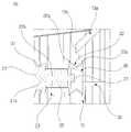
도 4는 본 발명에 따른 스팀 컨벡션 오븐의 물분사 장치의 개략 확대도.1 is a schematic perspective view showing a steam convection oven having a steam generator according to the prior art.
Figure 2 is a schematic diagram showing a water spray device of the steam convection oven according to the present invention.
Figure 3 is a schematic perspective view showing a water spray device of the steam convection oven according to the present invention.
4 is a schematic enlarged view of a water spraying device of a steam convection oven according to the present invention;
이하, 본 발명에 따른 스팀 컨벡션 오븐의 물분사 장치를 도 2 내지 도 4를 참조하여 설명하면 다음과 같다. 본 실시예에 대한 설명에서 종래 기술에서와 동일한 구성요소에 대해서는 이해의 편의를 위해 동일한 도면부호를 사용하였다.Hereinafter, a water spray device of the steam convection oven according to the present invention will be described with reference to FIGS. 2 to 4. In the description of this embodiment, the same reference numerals are used for the same components as those in the prior art for the sake of understanding.
본 발명에 따른 스팀 컨벡션 오븐의 물분사 장치는 외관을 형성하고 내부에 조리실을 구비하는 본체부와, 상기 본체부의 전측부에 제공되어 상기 조리실의 개구된 전면부를 개폐하는 도어와, 상기 본체부의 일측면에 제공되어 조리실의 온도를 조절하는 조작부와, 상기 본체부의 일측에 제공되고 상기 본체부의 조리실의 내부에 열과 증기를 공급하는 증기공급부를 포함하는 스팀 컨벡션 오븐에 적용된다.The water spraying apparatus of the steam convection oven according to the present invention includes a main body portion having an appearance and having a cooking chamber therein, a door provided at a front side of the main body portion to open and close an open front portion of the cooking chamber, and one of the main body portions. It is applied to the steam convection oven provided on the side including a control unit for adjusting the temperature of the cooking chamber, and a steam supply unit provided on one side of the main body portion and supplies heat and steam to the inside of the cooking chamber of the main body portion.
도 2와 도 3에 도시된 바와 같이, 상기 증기공급부(20)는 회전 샤프트(21)의 선단부에 둘레를 따라 제공되는 홈부(22)를 구비하고 상기 회전 샤프트(21)에 의해 회전되는 스프레이 유닛(23)을 포함하는 대류팬(24); 상기 본체부(3)에 지지되고 상기 대류팬(24)을 둘러싸는 형태로 배치되는 전기히터(12); 및 외부에서 상기 대류팬(24)측으로 뻗는 급수관(13)의 선단부에 제공되며, 상기 전기히터(12)로 물을 분사시킬 수 있도록 상기 스프레이 유닛(23)의 홈부(22)로 물을 토출시키는 분사노즐(13a);을 포함한다.
As shown in Fig. 2 and 3, the
전술한 바와 같은 본 발명에 따른 스팀 컨벡션 오븐의 물분사 장치는 대류팬(24)의 회전 샤프트(21)의 선단부에 둘레를 따라 제공되는 홈부(22)를 갖는 스프레이 유닛(23)과, 상기 스프레이 유닛(23)의 홈부(22)로 물을 토출시키는 분사노즐(13a)을 구비함으로써, 상기 분사노즐(13a)로부터 상기 스프레이 유닛(23)의 홈부(22)로 공급되는 물이 상기 스프레이 유닛(23)의 홈부(22)의 원심력에 의해 상기 홈부(22)의 반경방향 외측으로 비산되어 상기 전기히터(12)로 고르게 확산될 수 있게 된다. 또한 본 발명에 따른 스팀 컨벡션 오븐의 물분사 장치는 위와 같이 상기 분사노즐(13a)로부터 공급되는 물이 상기 스프레이 유닛(23)의 홈부(22)를 통해 상기 전기히터(12)로 고르게 전달됨으로써, 영역들 간의 온도차이를 발생시키지 않아 상기 전기히터(12)의 내구성을 크게 향상시킬 수 있다.
The water spraying device of the steam convection oven according to the present invention as described above has a
또한 본 발명에 따른 스팀 컨벡션 오븐의 물분사 장치는 위와 같은 기본구성에 아래와 같은 실시예들로 더 구체화된 형태로 제공될 수 있다.In addition, the water spraying device of the steam convection oven according to the present invention may be provided in a more specific form in the following embodiments in the basic configuration as described above.
일실시예로, 상기 스프레이 유닛(23)은 상기 대류팬(24)에 구비된 회전 샤프트(21)와, 상기 분사노즐(13a)로부터 공급되는 물을 상기 전기히터(12)로 분사시킬 수 있도록 도면에 구체적으로 일치되게 도시하지는 않았지만 직접 상기 회전 샤프트(21)의 선단부에 상기 회전 샤프트(21)의 둘레를 따라 홈부(22)가 형성된 형태로 구성될 수 있다(도 2와 도 3 참조). 이 경우, 상기 홈부(22)는 호형, 사각형, 또는 V자형 등의 다양한 형태로 이루어질 수 있지만 상기 분사노즐(13a)로부터 공급되는 물이 상기 회전 샤프트(21)의 원심력에 의해 반경방향 외측으로 고르게 잘 분산될 수 있도록 V자 형태로 이루어지는 것이 바람직하다.In an embodiment, the
또한 다른 실시예로, 상기 스프레이 유닛(23)은 도 2 내지 도 4에 도시된 바와 같은 형태로 형성되는 것도 가능하다. 상기 스프레이 유닛(23)은 길이를 따라 상기 대류팬(24)의 회전 샤프트(21) 내에 형성되고 내주면에 나사선을 갖는 나사선 타입 관통공(21a)과, 스페이서(25)와, 스프레이 부재(26)와, 볼트 부재(27)를 포함하는 형태로 제공될 수 있다. 상기 스페이서(26)는 상기 대류팬(24)의 회전 샤프트(21)의 선단부에 끼워지고 상기 회전 샤프트(21)의 나사선 타입 관통공(21a)과 동축을 이루도록 길이를 따라 관통공을 갖는다. 상기 스프레이 부재(26)는 상기 스페이서(25)의 선단부에 배치되고 중앙에 관통공을 가지며, 둘레를 따라 홈부(22)를 갖는다. 상기 볼트 부재(27)는 상기 스프레이 부재(26)와 상기 스페이서(25)를 상기 회전 샤프트(21)에 분리 가능하게 고정시킬 수 있도록 상기 회전 샤프트(21)의 나사선 타입 관통공(21a)에 체결된다.In another embodiment, the
이 경우, 상기 스페이서(25)는 상기 스프레이 부재(26)의 홈부(22)를 상기 스프레이 부재(26)의 홈부(22)와 상기 전기히터(12) 사이의 최적 위치에 편리하게 위치시킬 수 있게 하고 또한 상기 대류팬(24)의 하단부에 대해 상기 스프레이 부재(26)의 홈부(22)의 위치를 적절히 설정할 수 있게 한다. 이러한 홈부(22)의 이격구조는 종래에 상기 급수관(13)의 분사노즐(13a)을 통해 발생되는 미세 물분자가 상기 대류팬(24)의 하부에 발생되는 음압에 의해 상기 대류팬(24)의 하단부와 마주하는 상기 전기히터(12)의 일부 영역으로만 집중되는 현상을 방지한다. 한편, 상기 스페이서(25)는 미리 일정길이를 갖는 다수의 부품들로 제공되어 다양한 형태의 대류팬(24)의 설계 환경에 맞게 선택되어 사용될 수 있다. 상기 홈부(22)는 호형, 사각형, 또는 V자형 등의 다양한 형태로 이루어질 수 있지만 상기 분사노즐(13a)로부터 공급되는 물이 상기 회전 샤프트(21)의 원심력에 의해 반경방향 외측으로 고르게 잘 분산될 수 있도록 V자 형태로 이루어지는 것이 바람직하다.In this case, the
상기 두 실시예에서, 도 2 내지 도 4에 도시된 바와 같이, 상기 스프레이 부재(26)의 홈부(22)는 V자 형태를 이루고 상기 스프레이 부재(26)의 V자 홈부(22)의 양측 테두리 선단부에는 각각 반경방향 외측으로 뻗는 상부 확장 테두리부(22a)를 더 포함하는 형태로 제공될 수 있다. 상기 홈부(22)의 상부 확장 테두리부(22a)는 비교적 간단한 구조를 통해 상기 홈부(22)로부터 비산되는 물을 정확히 상기 전기히터(12)의 영역으로 효과적으로 유도시킨다.2 to 4, the
상기 두 실시예에서, 도 3과 도 4에 도시된 바와 같이, 상기 스프레이 부재(26)의 하부는 상기 스페이서(25)의 외면을 감싸는 형태로 상기 스페이서(25)에 끼워질 수 있도록 상기 스프레이 부재(26)의 하부로 뻗는 하부 확장 테두리부(22b)를 더 포함하는 형태로 제공될 수 있다. 상기 스프레이 부재(26)의 하부 확장 테두리부(22b)는 구조적으로 상기 스페이서(25)를 일정깊이로 수용하여 상기 스프레이 부재(26)를 상기 스페이서(25)에 보다 안정적으로 고정시키는 효과를 발휘한다.In the two embodiments, as shown in FIGS. 3 and 4, the lower portion of the
또한 본 발명에 따른 스팀 컨벡션 오븐의 물분사 장치에서, 도 3에 도시된 바와 같이, 상기 급수관(13)은 상기 분사노즐(13a)의 선단부가 상기 스프레이 유닛(23)으로 향하도록 굽힘부(13b)를 포함하고, 상기 분사노즐(13a)의 선단부는 상기 스프레이 유닛(23)의 홈부(22)와 대응되도록 경사 테두리면(13c)을 갖는 형태로 제공될 수 있다. 상기 급수관(13)의 굽힘부(13b)는 배치경로 상에서 장애를 일으키는 상대물을 용이하게 피할 수 있게 하거나 상기 분사노즐(13a)을 상기 스프레이 유닛(23)의 홈부(22)에 콤팩트한 구조로 적절히 배치시킬 수 있게 한다. 또한 상기 경사 테두리면(13c)은 상기 분사노즐(13a)의 길이방향에 대해 예컨대 45°정도의 각도를 이루는 절단면일 수 있다. 이러한 경사각도는 상기 분사노즐(13a)로부터 토출되는 물이 상기 경사 테두리면(13c)의 끝단부만으로 원활히 배출될 수 있게 하여 결과적으로 상기 토출되는 물이 상기 홈부(22)의 중앙부분으로 정확히 분사될 수 있게 한다.In addition, in the water spray device of the steam convection oven according to the present invention, as shown in Figure 3, the
또한 도 2와 도 3에 도시된 바와 같이, 상기 대류팬(24)은 중앙을 중심으로 둘레를 따라 일정간격으로 배치되는 다수의 팬 블레이드(30a)를 갖는 팬 블레이드부(30)를 포함하고, 상기 팬 블레이드부(30)는 상기 회전 샤프트(21)의 하부 외주면에 나사선 체결방식으로 분리 가능하게 고정되는 캡 너트(31)를 매개로 하여 고정될 수 있다.
2 and 3, the
전술한 바와 같은 본 발명에 따른 스팀 컨벡션 오븐의 물분사 장치의 바람직한 작용을 도 2 내지 도 4를 참조하여 설명하기로 한다.The preferred function of the water spray device of the steam convection oven according to the present invention as described above will be described with reference to FIGS.
먼저, 조리실(2) 내에 조리를 위한 음식물을 위치시킨 상태에서 조작부(미도시)를 통해 조리 작동을 시작하게 되면, 대류팬(24)과 전기히터(12)가 가동되면서 급수관(13)의 분사노즐(13a)로부터 상기 대류팬(24)의 회전 샤프트(21)의 선단부에 제공된 스프레이 유닛(23)의 홈부(22), 예컨대 V자 홈부로 물이 공급된다.First, when the cooking operation is started through an operation unit (not shown) in a state in which food for cooking is placed in the
이 때, 상기 스프레이 유닛(23)의 홈부(22)는 상기 대류팬(24)의 가동으로 회전되고 상기 홈부(22)로 공급되는 물은 상기 대류팬(24)의 회전에 따른 원심력에 의해 전기히터(12)로 비산된다.At this time, the
또한 상기 스프레이 유닛(23)의 홈부(22)의 양측 테두리 선단부에 각각 반경방향 외측으로 뻗는 상부 확장 테두리부(22a)를 더 포함하는 구조를 적용한 경우, 상기 홈부(22)의 상부 확장 테두리부(22a)는 상기 홈부(22)로부터 비산되는 물을 정확히 상기 전기히터(12)의 영역으로 효과적으로 유도시킬 수 있게 한다.In addition, when the structure further includes an upper
이어서, 상기 전기히터(12)로 비산되는 물은 상기 전기히터(12)에 의해 가열되면서 열과 스팀을 발생시키고 이러한 열과 스팀은 상기 대류팬(24)의 송풍력에 의해 상기 조리실(2)의 내부로 토출될 수 있게 된다. 그에 따라 상기 조리실(2) 내로 토출된 열과 스팀에 의해 음식물이 조리될 수 있게 된다. 이 후, 상기 조작부(미도시)를 통해 조리 작동을 정지시킨 후, 도어(미도시)를 개방하여 조리된 음식물을 꺼내면 된다.
Subsequently, water splashed into the
이상에서 설명한 본 발명은 전술한 실시예 및 첨부된 도면에 의해 한정되지 않으며, 본 발명의 기술적 사상 내에서의 단순 치환, 변형 및 변경은 당 분야에서의 통상의 지식을 가진 자에게 명백한 것이다.The present invention described above is not limited to the above-described embodiments and the accompanying drawings, and simple substitution, modification and alteration within the technical spirit of the present invention will be apparent to those skilled in the art.
2: 조리실 3: 본체부
12: 전기히터 13: 급수관
13a: 분사노즐 13b: 굽힘부
13c: 경사 테두리면 20: 증기공급부
21: 회전 샤프트 21a: 나사선 타입 관통공
22: 홈부 22a: 상부 확장 테두리부
22b: 하부 확장 테두리부 23: 스프레이 유닛
24: 대류팬 25: 스페이서
26: 스프레이 부재 27: 볼트 부재
30a: 팬 블레이드 30: 팬 블레이드부
31: 캡 너트2: cooking chamber 3:
12: electric heater 13: water supply pipe
13a:
13c: sloped edge 20: steam supply
21: rotating
22:
22b: lower extension edge 23: spray unit
24: convection fan 25: spacer
26: spray member 27: bolt member
30a: fan blade 30: fan blade part
31: cap nut
Claims (7)
Translated fromKorean상기 증기공급부는,
회전 샤프트의 선단부에 둘레를 따라 제공되는 홈부를 구비하고 상기 회전 샤프트에 의해 회전되는 스프레이 유닛을 포함하는 대류팬;
상기 본체부에 지지되고 상기 대류팬을 둘러싸는 형태로 배치되는 전기히터; 및
외부에서 상기 대류팬측으로 뻗는 급수관의 선단부에 제공되며, 상기 전기히터로 물을 분사시킬 수 있도록 상기 스프레이 유닛의 홈부로 물을 토출시키는 분사노즐;을 포함하며,
상기 스프레이 유닛은 상기 대류팬의 회전 샤프트의 선단부에 상기 회전 샤프트의 둘레를 따라 형성되는 홈부를 포함하고, 상기 홈부는 V자 형태인 것을 특징으로 하는 스팀 컨벡션 오븐의 물분사 장치.A main body part having an appearance and having a cooking compartment therein, a door provided at the front side of the main body part to open and close the opened front part of the cooking chamber, and an operation part provided at one side of the main body part to adjust the temperature of the cooking chamber; In the water injection device of the steam convection oven provided on one side of the main body portion and includes a steam supply for supplying heat and steam to the interior of the cooking chamber of the main body,
The steam supply unit,
A convection fan having a groove provided along the periphery of the rotary shaft and including a spray unit rotated by the rotary shaft;
An electric heater supported in the main body and disposed in a form surrounding the convection fan; And
And a spray nozzle provided at a front end of the water supply pipe extending from the outside to the convection fan and discharging water into the groove of the spray unit so as to spray water into the electric heater.
The spray unit includes a groove formed along the circumference of the rotary shaft in the front end portion of the rotary shaft of the convection fan, the groove portion is a V-shaped water injection device of the steam convection oven, characterized in that the.
상기 스프레이 유닛은 길이를 따라 상기 대류팬의 회전 샤프트 내에 형성되고 내주면에 나사선을 갖는 나사선 타입 관통공과,
상기 대류팬의 회전 샤프트의 선단부에 끼워지고 상기 회전 샤프트의 나사선 타입 관통공과 동축을 이루도록 길이를 따라 관통공을 갖는 스페이서 및 그 스페이서의 선단부에 배치되고 중앙에 관통공을 가지며 둘레를 따라 홈부를 갖는 스프레이 부재와,
상기 스프레이 부재와 상기 스페이서를 상기 회전 샤프트에 분리 가능하게 고정시킬 수 있도록 상기 회전 샤프트의 나사선 타입 관통공에 체결되는 볼트 부재로 구성된 것인 스팀 컨벡션 오븐의 물분사 장치.The method of claim 1,
The spray unit includes a thread-type through hole formed in the rotating shaft of the convection fan along its length and having a thread on an inner circumferential surface thereof;
A spacer having a through-hole along its length to be coaxial with a threaded-type through-hole of the rotary shaft and disposed at the distal end of the spacer, with a through-hole in the center, and a groove along the circumference With a spray member,
And a bolt member fastened to a threaded type through hole of the rotary shaft to detachably fix the spray member and the spacer to the rotary shaft.
상기 스프레이 부재의 홈부는 V자 형태를 이루고, 상기 스프레이 부재의 V자 홈부의 양측 테두리 선단부는 각각 반경방향 외측으로 뻗는 상부 확장 테두리부를 더 포함하는 것인 스팀 컨벡션 오븐의 물분사 장치.The method of claim 3, wherein
The groove portion of the spray member forms a V-shape, and both edges of the V-shaped groove portion of the spray member further comprises an upper extended edge portion extending radially outward, respectively.
상기 스프레이 부재의 하부는 상기 스페이서의 외면을 감싸는 형태로 상기 스페이서에 끼워질 수 있도록 상기 스프레이 부재의 하부로 뻗는 하부 확장 테두리부를 더 포함하는 것인 스팀 컨벡션 오븐의 물분사 장치.The method of claim 3, wherein
The lower portion of the spray member further comprises a lower extending edge portion extending to the lower portion of the spray member so as to be fitted to the spacer in a form surrounding the outer surface of the spacer water injection apparatus of the steam convection oven.
상기 급수관은 상기 분사노즐의 선단부가 상기 스프레이 유닛으로 향하도록 굽힘부를 포함하고, 상기 분사노즐의 선단부는 상기 스프레이 유닛의 홈부와 대응되도록 경사 테두리면을 갖는 것인 스팀 컨벡션 오븐의 물분사 장치.The method of claim 1,
The water supply pipe includes a bent portion so that the tip end of the injection nozzle toward the spray unit, the tip end of the injection nozzle has a slanted rim surface so as to correspond to the groove portion of the spray unit.
상기 대류팬은 중앙을 중심으로 둘레를 따라 일정간격으로 배치되는 다수의 팬 블레이드를 갖는 팬 블레이드부를 포함하고, 상기 팬 블레이드부는 상기 회전 샤프트의 하부 외주면에 나사선 체결방식으로 분리 가능하게 고정되는 캡 너트를 매개로 하여 고정되는 것인 스팀 컨벡션 오븐의 물분사 장치.The method of claim 1,
The convection fan includes a fan blade portion having a plurality of fan blades disposed at regular intervals along a circumference of the center, and the fan blade portion is detachably fixed to the lower outer circumferential surface of the rotating shaft by a screw fastening method. The water spraying device of the steam convection oven is fixed via.
Priority Applications (1)
| Application Number | Priority Date | Filing Date | Title |
|---|---|---|---|
| KR1020120092714AKR101359460B1 (en) | 2012-08-24 | 2012-08-24 | Water spray structure of a steam convection oven |
Applications Claiming Priority (1)
| Application Number | Priority Date | Filing Date | Title |
|---|---|---|---|
| KR1020120092714AKR101359460B1 (en) | 2012-08-24 | 2012-08-24 | Water spray structure of a steam convection oven |
Publications (1)
| Publication Number | Publication Date |
|---|---|
| KR101359460B1true KR101359460B1 (en) | 2014-02-10 |
Family
ID=50270087
Family Applications (1)
| Application Number | Title | Priority Date | Filing Date |
|---|---|---|---|
| KR1020120092714AActiveKR101359460B1 (en) | 2012-08-24 | 2012-08-24 | Water spray structure of a steam convection oven |
Country Status (1)
| Country | Link |
|---|---|
| KR (1) | KR101359460B1 (en) |
Cited By (15)
| Publication number | Priority date | Publication date | Assignee | Title |
|---|---|---|---|---|
| WO2018102984A1 (en)* | 2016-12-06 | 2018-06-14 | Whirlpool Corporation | Moisture convection for microwave oven |
| US10560986B2 (en) | 2013-08-20 | 2020-02-11 | Whirlpool Corporation | Method for detecting the status of popcorn in a microwave |
| US10764970B2 (en) | 2016-01-08 | 2020-09-01 | Whirlpool Corporation | Multiple cavity microwave oven insulated divider |
| US10772165B2 (en) | 2018-03-02 | 2020-09-08 | Whirlpool Corporation | System and method for zone cooking according to spectromodal theory in an electromagnetic cooking device |
| US10820382B2 (en) | 2016-01-28 | 2020-10-27 | Whirlpool Corporation | Method and apparatus for delivering radio frequency electromagnetic energy to cook foodstuff |
| US10827569B2 (en) | 2017-09-01 | 2020-11-03 | Whirlpool Corporation | Crispness and browning in full flat microwave oven |
| US10827570B2 (en) | 2016-02-15 | 2020-11-03 | Whirlpool Corporation | Method and apparatus for delivering radio frequency electromagnetic energy to cook foodstuff |
| US10904961B2 (en) | 2015-03-06 | 2021-01-26 | Whirlpool Corporation | Method of calibrating a high power amplifier for a radio frequency power measurement system |
| US10904962B2 (en) | 2015-06-03 | 2021-01-26 | Whirlpool Corporation | Method and device for electromagnetic cooking |
| US10912160B2 (en) | 2018-07-19 | 2021-02-02 | Whirlpool Corporation | Cooking appliance |
| US10993293B2 (en) | 2013-12-23 | 2021-04-27 | Whirlpool Corporation | Interrupting circuit for a radio frequency generator |
| US11039510B2 (en) | 2017-09-27 | 2021-06-15 | Whirlpool Corporation | Method and device for electromagnetic cooking using asynchronous sensing strategy for resonant modes real-time tracking |
| US11191133B2 (en) | 2014-09-17 | 2021-11-30 | Whirlpool Corporation | Direct heating through patch antennas |
| US11404758B2 (en) | 2018-05-04 | 2022-08-02 | Whirlpool Corporation | In line e-probe waveguide transition |
| US11483905B2 (en) | 2016-01-08 | 2022-10-25 | Whirlpool Corporation | Method and apparatus for determining heating strategies |
Citations (4)
| Publication number | Priority date | Publication date | Assignee | Title |
|---|---|---|---|---|
| KR100382280B1 (en) | 2000-06-05 | 2003-05-01 | 김대인 | Convection oven |
| KR20030095661A (en)* | 2002-06-14 | 2003-12-24 | 대영제과제빵기계공업주식회사 | Convection ovens |
| JP2007057144A (en) | 2005-08-24 | 2007-03-08 | Densoku:Kk | Steam oven |
| JP2011141098A (en) | 2010-01-08 | 2011-07-21 | Kometsuto Kato:Kk | Steam convection oven |
- 2012
- 2012-08-24KRKR1020120092714Apatent/KR101359460B1/enactiveActive
Patent Citations (4)
| Publication number | Priority date | Publication date | Assignee | Title |
|---|---|---|---|---|
| KR100382280B1 (en) | 2000-06-05 | 2003-05-01 | 김대인 | Convection oven |
| KR20030095661A (en)* | 2002-06-14 | 2003-12-24 | 대영제과제빵기계공업주식회사 | Convection ovens |
| JP2007057144A (en) | 2005-08-24 | 2007-03-08 | Densoku:Kk | Steam oven |
| JP2011141098A (en) | 2010-01-08 | 2011-07-21 | Kometsuto Kato:Kk | Steam convection oven |
Cited By (17)
| Publication number | Priority date | Publication date | Assignee | Title |
|---|---|---|---|---|
| US10560986B2 (en) | 2013-08-20 | 2020-02-11 | Whirlpool Corporation | Method for detecting the status of popcorn in a microwave |
| US11102855B2 (en) | 2013-08-20 | 2021-08-24 | Whirlpool Corporation | Method for detecting the status of popcorn in a microwave |
| US12302482B2 (en) | 2013-12-23 | 2025-05-13 | Whirlpool Corporation | Interrupting circuit for a radio frequency generator |
| US10993293B2 (en) | 2013-12-23 | 2021-04-27 | Whirlpool Corporation | Interrupting circuit for a radio frequency generator |
| US11191133B2 (en) | 2014-09-17 | 2021-11-30 | Whirlpool Corporation | Direct heating through patch antennas |
| US10904961B2 (en) | 2015-03-06 | 2021-01-26 | Whirlpool Corporation | Method of calibrating a high power amplifier for a radio frequency power measurement system |
| US10904962B2 (en) | 2015-06-03 | 2021-01-26 | Whirlpool Corporation | Method and device for electromagnetic cooking |
| US11483905B2 (en) | 2016-01-08 | 2022-10-25 | Whirlpool Corporation | Method and apparatus for determining heating strategies |
| US10764970B2 (en) | 2016-01-08 | 2020-09-01 | Whirlpool Corporation | Multiple cavity microwave oven insulated divider |
| US10820382B2 (en) | 2016-01-28 | 2020-10-27 | Whirlpool Corporation | Method and apparatus for delivering radio frequency electromagnetic energy to cook foodstuff |
| US10827570B2 (en) | 2016-02-15 | 2020-11-03 | Whirlpool Corporation | Method and apparatus for delivering radio frequency electromagnetic energy to cook foodstuff |
| WO2018102984A1 (en)* | 2016-12-06 | 2018-06-14 | Whirlpool Corporation | Moisture convection for microwave oven |
| US10827569B2 (en) | 2017-09-01 | 2020-11-03 | Whirlpool Corporation | Crispness and browning in full flat microwave oven |
| US11039510B2 (en) | 2017-09-27 | 2021-06-15 | Whirlpool Corporation | Method and device for electromagnetic cooking using asynchronous sensing strategy for resonant modes real-time tracking |
| US10772165B2 (en) | 2018-03-02 | 2020-09-08 | Whirlpool Corporation | System and method for zone cooking according to spectromodal theory in an electromagnetic cooking device |
| US11404758B2 (en) | 2018-05-04 | 2022-08-02 | Whirlpool Corporation | In line e-probe waveguide transition |
| US10912160B2 (en) | 2018-07-19 | 2021-02-02 | Whirlpool Corporation | Cooking appliance |
Similar Documents
| Publication | Publication Date | Title |
|---|---|---|
| KR101359460B1 (en) | Water spray structure of a steam convection oven | |
| RU2698745C1 (en) | Device and method for preparation of food ingredients due to hot air and fluid medium supplied thereto | |
| US11116359B2 (en) | Apparatus and method for preparing food | |
| CN208192787U (en) | Steam sprays cooking apparatus | |
| RU2577428C2 (en) | Fan metal fibre gas torch | |
| EP2275745B1 (en) | A cooking oven with at least one convection heating device | |
| KR20160093858A (en) | Convection oven | |
| KR101461402B1 (en) | A roasting apparatus | |
| KR200448527Y1 (en) | Large capacity cookware | |
| KR20130123554A (en) | Steam oven | |
| KR100645031B1 (en) | Top down grill | |
| KR20170056738A (en) | Cyclone injection type Steam nozzle of instant food cooking equipment | |
| JP6030286B2 (en) | rice cooker | |
| KR101401284B1 (en) | Apparatus for hybrid ventilation and hybrid ventilation system | |
| KR20130028319A (en) | Steam convection oven | |
| KR101575566B1 (en) | Oven | |
| JP6629099B2 (en) | Cooking device | |
| KR101439319B1 (en) | Water direct injection type steam oven | |
| KR102132838B1 (en) | Vapor convection type oven | |
| KR102514304B1 (en) | Cooking appliance | |
| KR200490708Y1 (en) | Steaming machine | |
| EP3770511A1 (en) | Electric convection cooking oven and method of operation of such an oven | |
| KR20170056740A (en) | Instant food cooking apparatus is available cleaning the steam nozzle | |
| KR20150064942A (en) | Are equipped with steam function Roaster | |
| EP3722679B1 (en) | Professional cooking oven with steam generator |
Legal Events
| Date | Code | Title | Description |
|---|---|---|---|
| A201 | Request for examination | ||
| PA0109 | Patent application | Patent event code:PA01091R01D Comment text:Patent Application Patent event date:20120824 | |
| PA0201 | Request for examination | ||
| E902 | Notification of reason for refusal | ||
| PE0902 | Notice of grounds for rejection | Comment text:Notification of reason for refusal Patent event date:20131108 Patent event code:PE09021S01D | |
| E701 | Decision to grant or registration of patent right | ||
| PE0701 | Decision of registration | Patent event code:PE07011S01D Comment text:Decision to Grant Registration Patent event date:20140128 | |
| GRNT | Written decision to grant | ||
| PR0701 | Registration of establishment | Comment text:Registration of Establishment Patent event date:20140129 Patent event code:PR07011E01D | |
| PR1002 | Payment of registration fee | Payment date:20140129 End annual number:3 Start annual number:1 | |
| PG1601 | Publication of registration | ||
| FPAY | Annual fee payment | Payment date:20161228 Year of fee payment:6 | |
| PR1001 | Payment of annual fee | Payment date:20161228 Start annual number:4 End annual number:6 | |
| FPAY | Annual fee payment | Payment date:20200102 Year of fee payment:7 | |
| PR1001 | Payment of annual fee | Payment date:20200102 Start annual number:7 End annual number:7 | |
| PR1001 | Payment of annual fee | Payment date:20210104 Start annual number:8 End annual number:8 | |
| PR1001 | Payment of annual fee | Payment date:20220103 Start annual number:9 End annual number:9 | |
| PR1001 | Payment of annual fee | Payment date:20230102 Start annual number:10 End annual number:10 | |
| PR1001 | Payment of annual fee | Payment date:20240102 Start annual number:11 End annual number:11 | |
| PR1001 | Payment of annual fee | Payment date:20241226 Start annual number:12 End annual number:12 |