KR101358560B1 - Transforaminal intersomatic cage and an instrument for implanting the cage - Google Patents
Transforaminal intersomatic cage and an instrument for implanting the cageDownload PDFInfo
- Publication number
- KR101358560B1 KR101358560B1KR1020087022303AKR20087022303AKR101358560B1KR 101358560 B1KR101358560 B1KR 101358560B1KR 1020087022303 AKR1020087022303 AKR 1020087022303AKR 20087022303 AKR20087022303 AKR 20087022303AKR 101358560 B1KR101358560 B1KR 101358560B1
- Authority
- KR
- South Korea
- Prior art keywords
- cage
- intersomatic
- intersomatic cage
- delete delete
- serration
- Prior art date
- Legal status (The legal status is an assumption and is not a legal conclusion. Google has not performed a legal analysis and makes no representation as to the accuracy of the status listed.)
- Expired - Fee Related
Links
Images


Classifications
- A—HUMAN NECESSITIES
- A61—MEDICAL OR VETERINARY SCIENCE; HYGIENE
- A61F—FILTERS IMPLANTABLE INTO BLOOD VESSELS; PROSTHESES; DEVICES PROVIDING PATENCY TO, OR PREVENTING COLLAPSING OF, TUBULAR STRUCTURES OF THE BODY, e.g. STENTS; ORTHOPAEDIC, NURSING OR CONTRACEPTIVE DEVICES; FOMENTATION; TREATMENT OR PROTECTION OF EYES OR EARS; BANDAGES, DRESSINGS OR ABSORBENT PADS; FIRST-AID KITS
- A61F2/00—Filters implantable into blood vessels; Prostheses, i.e. artificial substitutes or replacements for parts of the body; Appliances for connecting them with the body; Devices providing patency to, or preventing collapsing of, tubular structures of the body, e.g. stents
- A61F2/02—Prostheses implantable into the body
- A61F2/30—Joints
- A61F2/44—Joints for the spine, e.g. vertebrae, spinal discs
- A61F2/4455—Joints for the spine, e.g. vertebrae, spinal discs for the fusion of spinal bodies, e.g. intervertebral fusion of adjacent spinal bodies, e.g. fusion cages
- A—HUMAN NECESSITIES
- A61—MEDICAL OR VETERINARY SCIENCE; HYGIENE
- A61F—FILTERS IMPLANTABLE INTO BLOOD VESSELS; PROSTHESES; DEVICES PROVIDING PATENCY TO, OR PREVENTING COLLAPSING OF, TUBULAR STRUCTURES OF THE BODY, e.g. STENTS; ORTHOPAEDIC, NURSING OR CONTRACEPTIVE DEVICES; FOMENTATION; TREATMENT OR PROTECTION OF EYES OR EARS; BANDAGES, DRESSINGS OR ABSORBENT PADS; FIRST-AID KITS
- A61F2/00—Filters implantable into blood vessels; Prostheses, i.e. artificial substitutes or replacements for parts of the body; Appliances for connecting them with the body; Devices providing patency to, or preventing collapsing of, tubular structures of the body, e.g. stents
- A61F2/02—Prostheses implantable into the body
- A61F2/30—Joints
- A61F2/46—Special tools for implanting artificial joints
- A—HUMAN NECESSITIES
- A61—MEDICAL OR VETERINARY SCIENCE; HYGIENE
- A61F—FILTERS IMPLANTABLE INTO BLOOD VESSELS; PROSTHESES; DEVICES PROVIDING PATENCY TO, OR PREVENTING COLLAPSING OF, TUBULAR STRUCTURES OF THE BODY, e.g. STENTS; ORTHOPAEDIC, NURSING OR CONTRACEPTIVE DEVICES; FOMENTATION; TREATMENT OR PROTECTION OF EYES OR EARS; BANDAGES, DRESSINGS OR ABSORBENT PADS; FIRST-AID KITS
- A61F2/00—Filters implantable into blood vessels; Prostheses, i.e. artificial substitutes or replacements for parts of the body; Appliances for connecting them with the body; Devices providing patency to, or preventing collapsing of, tubular structures of the body, e.g. stents
- A61F2/02—Prostheses implantable into the body
- A61F2/30—Joints
- A61F2/44—Joints for the spine, e.g. vertebrae, spinal discs
- A—HUMAN NECESSITIES
- A61—MEDICAL OR VETERINARY SCIENCE; HYGIENE
- A61F—FILTERS IMPLANTABLE INTO BLOOD VESSELS; PROSTHESES; DEVICES PROVIDING PATENCY TO, OR PREVENTING COLLAPSING OF, TUBULAR STRUCTURES OF THE BODY, e.g. STENTS; ORTHOPAEDIC, NURSING OR CONTRACEPTIVE DEVICES; FOMENTATION; TREATMENT OR PROTECTION OF EYES OR EARS; BANDAGES, DRESSINGS OR ABSORBENT PADS; FIRST-AID KITS
- A61F2/00—Filters implantable into blood vessels; Prostheses, i.e. artificial substitutes or replacements for parts of the body; Appliances for connecting them with the body; Devices providing patency to, or preventing collapsing of, tubular structures of the body, e.g. stents
- A61F2/02—Prostheses implantable into the body
- A61F2/30—Joints
- A61F2/46—Special tools for implanting artificial joints
- A61F2/4603—Special tools for implanting artificial joints for insertion or extraction of endoprosthetic joints or of accessories thereof
- A61F2/4611—Special tools for implanting artificial joints for insertion or extraction of endoprosthetic joints or of accessories thereof of spinal prostheses
- A—HUMAN NECESSITIES
- A61—MEDICAL OR VETERINARY SCIENCE; HYGIENE
- A61F—FILTERS IMPLANTABLE INTO BLOOD VESSELS; PROSTHESES; DEVICES PROVIDING PATENCY TO, OR PREVENTING COLLAPSING OF, TUBULAR STRUCTURES OF THE BODY, e.g. STENTS; ORTHOPAEDIC, NURSING OR CONTRACEPTIVE DEVICES; FOMENTATION; TREATMENT OR PROTECTION OF EYES OR EARS; BANDAGES, DRESSINGS OR ABSORBENT PADS; FIRST-AID KITS
- A61F2/00—Filters implantable into blood vessels; Prostheses, i.e. artificial substitutes or replacements for parts of the body; Appliances for connecting them with the body; Devices providing patency to, or preventing collapsing of, tubular structures of the body, e.g. stents
- A61F2/02—Prostheses implantable into the body
- A61F2/28—Bones
- A61F2002/2835—Bone graft implants for filling a bony defect or an endoprosthesis cavity, e.g. by synthetic material or biological material
- A—HUMAN NECESSITIES
- A61—MEDICAL OR VETERINARY SCIENCE; HYGIENE
- A61F—FILTERS IMPLANTABLE INTO BLOOD VESSELS; PROSTHESES; DEVICES PROVIDING PATENCY TO, OR PREVENTING COLLAPSING OF, TUBULAR STRUCTURES OF THE BODY, e.g. STENTS; ORTHOPAEDIC, NURSING OR CONTRACEPTIVE DEVICES; FOMENTATION; TREATMENT OR PROTECTION OF EYES OR EARS; BANDAGES, DRESSINGS OR ABSORBENT PADS; FIRST-AID KITS
- A61F2/00—Filters implantable into blood vessels; Prostheses, i.e. artificial substitutes or replacements for parts of the body; Appliances for connecting them with the body; Devices providing patency to, or preventing collapsing of, tubular structures of the body, e.g. stents
- A61F2/02—Prostheses implantable into the body
- A61F2/30—Joints
- A61F2002/30001—Additional features of subject-matter classified in A61F2/28, A61F2/30 and subgroups thereof
- A61F2002/30003—Material related properties of the prosthesis or of a coating on the prosthesis
- A61F2002/3006—Properties of materials and coating materials
- A61F2002/3008—Properties of materials and coating materials radio-opaque, e.g. radio-opaque markers
- A—HUMAN NECESSITIES
- A61—MEDICAL OR VETERINARY SCIENCE; HYGIENE
- A61F—FILTERS IMPLANTABLE INTO BLOOD VESSELS; PROSTHESES; DEVICES PROVIDING PATENCY TO, OR PREVENTING COLLAPSING OF, TUBULAR STRUCTURES OF THE BODY, e.g. STENTS; ORTHOPAEDIC, NURSING OR CONTRACEPTIVE DEVICES; FOMENTATION; TREATMENT OR PROTECTION OF EYES OR EARS; BANDAGES, DRESSINGS OR ABSORBENT PADS; FIRST-AID KITS
- A61F2/00—Filters implantable into blood vessels; Prostheses, i.e. artificial substitutes or replacements for parts of the body; Appliances for connecting them with the body; Devices providing patency to, or preventing collapsing of, tubular structures of the body, e.g. stents
- A61F2/02—Prostheses implantable into the body
- A61F2/30—Joints
- A61F2002/30001—Additional features of subject-matter classified in A61F2/28, A61F2/30 and subgroups thereof
- A61F2002/30108—Shapes
- A61F2002/3011—Cross-sections or two-dimensional shapes
- A61F2002/30112—Rounded shapes, e.g. with rounded corners
- A61F2002/30131—Rounded shapes, e.g. with rounded corners horseshoe- or crescent- or C-shaped or U-shaped
- A—HUMAN NECESSITIES
- A61—MEDICAL OR VETERINARY SCIENCE; HYGIENE
- A61F—FILTERS IMPLANTABLE INTO BLOOD VESSELS; PROSTHESES; DEVICES PROVIDING PATENCY TO, OR PREVENTING COLLAPSING OF, TUBULAR STRUCTURES OF THE BODY, e.g. STENTS; ORTHOPAEDIC, NURSING OR CONTRACEPTIVE DEVICES; FOMENTATION; TREATMENT OR PROTECTION OF EYES OR EARS; BANDAGES, DRESSINGS OR ABSORBENT PADS; FIRST-AID KITS
- A61F2/00—Filters implantable into blood vessels; Prostheses, i.e. artificial substitutes or replacements for parts of the body; Appliances for connecting them with the body; Devices providing patency to, or preventing collapsing of, tubular structures of the body, e.g. stents
- A61F2/02—Prostheses implantable into the body
- A61F2/30—Joints
- A61F2002/30001—Additional features of subject-matter classified in A61F2/28, A61F2/30 and subgroups thereof
- A61F2002/30108—Shapes
- A61F2002/3011—Cross-sections or two-dimensional shapes
- A61F2002/30182—Other shapes
- A61F2002/30192—J-shaped
- A—HUMAN NECESSITIES
- A61—MEDICAL OR VETERINARY SCIENCE; HYGIENE
- A61F—FILTERS IMPLANTABLE INTO BLOOD VESSELS; PROSTHESES; DEVICES PROVIDING PATENCY TO, OR PREVENTING COLLAPSING OF, TUBULAR STRUCTURES OF THE BODY, e.g. STENTS; ORTHOPAEDIC, NURSING OR CONTRACEPTIVE DEVICES; FOMENTATION; TREATMENT OR PROTECTION OF EYES OR EARS; BANDAGES, DRESSINGS OR ABSORBENT PADS; FIRST-AID KITS
- A61F2/00—Filters implantable into blood vessels; Prostheses, i.e. artificial substitutes or replacements for parts of the body; Appliances for connecting them with the body; Devices providing patency to, or preventing collapsing of, tubular structures of the body, e.g. stents
- A61F2/02—Prostheses implantable into the body
- A61F2/30—Joints
- A61F2002/30001—Additional features of subject-matter classified in A61F2/28, A61F2/30 and subgroups thereof
- A61F2002/30108—Shapes
- A61F2002/30199—Three-dimensional shapes
- A61F2002/30308—Three-dimensional shapes banana-shaped
- A—HUMAN NECESSITIES
- A61—MEDICAL OR VETERINARY SCIENCE; HYGIENE
- A61F—FILTERS IMPLANTABLE INTO BLOOD VESSELS; PROSTHESES; DEVICES PROVIDING PATENCY TO, OR PREVENTING COLLAPSING OF, TUBULAR STRUCTURES OF THE BODY, e.g. STENTS; ORTHOPAEDIC, NURSING OR CONTRACEPTIVE DEVICES; FOMENTATION; TREATMENT OR PROTECTION OF EYES OR EARS; BANDAGES, DRESSINGS OR ABSORBENT PADS; FIRST-AID KITS
- A61F2/00—Filters implantable into blood vessels; Prostheses, i.e. artificial substitutes or replacements for parts of the body; Appliances for connecting them with the body; Devices providing patency to, or preventing collapsing of, tubular structures of the body, e.g. stents
- A61F2/02—Prostheses implantable into the body
- A61F2/30—Joints
- A61F2002/30001—Additional features of subject-matter classified in A61F2/28, A61F2/30 and subgroups thereof
- A61F2002/30316—The prosthesis having different structural features at different locations within the same prosthesis; Connections between prosthetic parts; Special structural features of bone or joint prostheses not otherwise provided for
- A61F2002/30535—Special structural features of bone or joint prostheses not otherwise provided for
- A61F2002/30576—Special structural features of bone or joint prostheses not otherwise provided for with extending fixation tabs
- A—HUMAN NECESSITIES
- A61—MEDICAL OR VETERINARY SCIENCE; HYGIENE
- A61F—FILTERS IMPLANTABLE INTO BLOOD VESSELS; PROSTHESES; DEVICES PROVIDING PATENCY TO, OR PREVENTING COLLAPSING OF, TUBULAR STRUCTURES OF THE BODY, e.g. STENTS; ORTHOPAEDIC, NURSING OR CONTRACEPTIVE DEVICES; FOMENTATION; TREATMENT OR PROTECTION OF EYES OR EARS; BANDAGES, DRESSINGS OR ABSORBENT PADS; FIRST-AID KITS
- A61F2/00—Filters implantable into blood vessels; Prostheses, i.e. artificial substitutes or replacements for parts of the body; Appliances for connecting them with the body; Devices providing patency to, or preventing collapsing of, tubular structures of the body, e.g. stents
- A61F2/02—Prostheses implantable into the body
- A61F2/30—Joints
- A61F2002/30001—Additional features of subject-matter classified in A61F2/28, A61F2/30 and subgroups thereof
- A61F2002/30316—The prosthesis having different structural features at different locations within the same prosthesis; Connections between prosthetic parts; Special structural features of bone or joint prostheses not otherwise provided for
- A61F2002/30535—Special structural features of bone or joint prostheses not otherwise provided for
- A61F2002/30579—Special structural features of bone or joint prostheses not otherwise provided for with mechanically expandable devices, e.g. fixation devices
- A—HUMAN NECESSITIES
- A61—MEDICAL OR VETERINARY SCIENCE; HYGIENE
- A61F—FILTERS IMPLANTABLE INTO BLOOD VESSELS; PROSTHESES; DEVICES PROVIDING PATENCY TO, OR PREVENTING COLLAPSING OF, TUBULAR STRUCTURES OF THE BODY, e.g. STENTS; ORTHOPAEDIC, NURSING OR CONTRACEPTIVE DEVICES; FOMENTATION; TREATMENT OR PROTECTION OF EYES OR EARS; BANDAGES, DRESSINGS OR ABSORBENT PADS; FIRST-AID KITS
- A61F2/00—Filters implantable into blood vessels; Prostheses, i.e. artificial substitutes or replacements for parts of the body; Appliances for connecting them with the body; Devices providing patency to, or preventing collapsing of, tubular structures of the body, e.g. stents
- A61F2/02—Prostheses implantable into the body
- A61F2/30—Joints
- A61F2002/30001—Additional features of subject-matter classified in A61F2/28, A61F2/30 and subgroups thereof
- A61F2002/30316—The prosthesis having different structural features at different locations within the same prosthesis; Connections between prosthetic parts; Special structural features of bone or joint prostheses not otherwise provided for
- A61F2002/30535—Special structural features of bone or joint prostheses not otherwise provided for
- A61F2002/30594—Special structural features of bone or joint prostheses not otherwise provided for slotted, e.g. radial or meridian slot ending in a polar aperture, non-polar slots, horizontal or arcuate slots
- A—HUMAN NECESSITIES
- A61—MEDICAL OR VETERINARY SCIENCE; HYGIENE
- A61F—FILTERS IMPLANTABLE INTO BLOOD VESSELS; PROSTHESES; DEVICES PROVIDING PATENCY TO, OR PREVENTING COLLAPSING OF, TUBULAR STRUCTURES OF THE BODY, e.g. STENTS; ORTHOPAEDIC, NURSING OR CONTRACEPTIVE DEVICES; FOMENTATION; TREATMENT OR PROTECTION OF EYES OR EARS; BANDAGES, DRESSINGS OR ABSORBENT PADS; FIRST-AID KITS
- A61F2/00—Filters implantable into blood vessels; Prostheses, i.e. artificial substitutes or replacements for parts of the body; Appliances for connecting them with the body; Devices providing patency to, or preventing collapsing of, tubular structures of the body, e.g. stents
- A61F2/02—Prostheses implantable into the body
- A61F2/30—Joints
- A61F2/30767—Special external or bone-contacting surface, e.g. coating for improving bone ingrowth
- A61F2/30771—Special external or bone-contacting surface, e.g. coating for improving bone ingrowth applied in original prostheses, e.g. holes or grooves
- A61F2002/30795—Blind bores, e.g. of circular cross-section
- A—HUMAN NECESSITIES
- A61—MEDICAL OR VETERINARY SCIENCE; HYGIENE
- A61F—FILTERS IMPLANTABLE INTO BLOOD VESSELS; PROSTHESES; DEVICES PROVIDING PATENCY TO, OR PREVENTING COLLAPSING OF, TUBULAR STRUCTURES OF THE BODY, e.g. STENTS; ORTHOPAEDIC, NURSING OR CONTRACEPTIVE DEVICES; FOMENTATION; TREATMENT OR PROTECTION OF EYES OR EARS; BANDAGES, DRESSINGS OR ABSORBENT PADS; FIRST-AID KITS
- A61F2/00—Filters implantable into blood vessels; Prostheses, i.e. artificial substitutes or replacements for parts of the body; Appliances for connecting them with the body; Devices providing patency to, or preventing collapsing of, tubular structures of the body, e.g. stents
- A61F2/02—Prostheses implantable into the body
- A61F2/30—Joints
- A61F2/30767—Special external or bone-contacting surface, e.g. coating for improving bone ingrowth
- A61F2/30771—Special external or bone-contacting surface, e.g. coating for improving bone ingrowth applied in original prostheses, e.g. holes or grooves
- A61F2002/30841—Sharp anchoring protrusions for impaction into the bone, e.g. sharp pins, spikes
- A61F2002/30845—Sharp anchoring protrusions for impaction into the bone, e.g. sharp pins, spikes with cutting edges
- A—HUMAN NECESSITIES
- A61—MEDICAL OR VETERINARY SCIENCE; HYGIENE
- A61F—FILTERS IMPLANTABLE INTO BLOOD VESSELS; PROSTHESES; DEVICES PROVIDING PATENCY TO, OR PREVENTING COLLAPSING OF, TUBULAR STRUCTURES OF THE BODY, e.g. STENTS; ORTHOPAEDIC, NURSING OR CONTRACEPTIVE DEVICES; FOMENTATION; TREATMENT OR PROTECTION OF EYES OR EARS; BANDAGES, DRESSINGS OR ABSORBENT PADS; FIRST-AID KITS
- A61F2/00—Filters implantable into blood vessels; Prostheses, i.e. artificial substitutes or replacements for parts of the body; Appliances for connecting them with the body; Devices providing patency to, or preventing collapsing of, tubular structures of the body, e.g. stents
- A61F2/02—Prostheses implantable into the body
- A61F2/30—Joints
- A61F2/30767—Special external or bone-contacting surface, e.g. coating for improving bone ingrowth
- A61F2/30771—Special external or bone-contacting surface, e.g. coating for improving bone ingrowth applied in original prostheses, e.g. holes or grooves
- A61F2002/30878—Special external or bone-contacting surface, e.g. coating for improving bone ingrowth applied in original prostheses, e.g. holes or grooves with non-sharp protrusions, for instance contacting the bone for anchoring, e.g. keels, pegs, pins, posts, shanks, stems, struts
- A61F2002/30879—Ribs
- A—HUMAN NECESSITIES
- A61—MEDICAL OR VETERINARY SCIENCE; HYGIENE
- A61F—FILTERS IMPLANTABLE INTO BLOOD VESSELS; PROSTHESES; DEVICES PROVIDING PATENCY TO, OR PREVENTING COLLAPSING OF, TUBULAR STRUCTURES OF THE BODY, e.g. STENTS; ORTHOPAEDIC, NURSING OR CONTRACEPTIVE DEVICES; FOMENTATION; TREATMENT OR PROTECTION OF EYES OR EARS; BANDAGES, DRESSINGS OR ABSORBENT PADS; FIRST-AID KITS
- A61F2/00—Filters implantable into blood vessels; Prostheses, i.e. artificial substitutes or replacements for parts of the body; Appliances for connecting them with the body; Devices providing patency to, or preventing collapsing of, tubular structures of the body, e.g. stents
- A61F2/02—Prostheses implantable into the body
- A61F2/30—Joints
- A61F2/30767—Special external or bone-contacting surface, e.g. coating for improving bone ingrowth
- A61F2/30771—Special external or bone-contacting surface, e.g. coating for improving bone ingrowth applied in original prostheses, e.g. holes or grooves
- A61F2002/30878—Special external or bone-contacting surface, e.g. coating for improving bone ingrowth applied in original prostheses, e.g. holes or grooves with non-sharp protrusions, for instance contacting the bone for anchoring, e.g. keels, pegs, pins, posts, shanks, stems, struts
- A61F2002/30884—Fins or wings, e.g. longitudinal wings for preventing rotation within the bone cavity
- A—HUMAN NECESSITIES
- A61—MEDICAL OR VETERINARY SCIENCE; HYGIENE
- A61F—FILTERS IMPLANTABLE INTO BLOOD VESSELS; PROSTHESES; DEVICES PROVIDING PATENCY TO, OR PREVENTING COLLAPSING OF, TUBULAR STRUCTURES OF THE BODY, e.g. STENTS; ORTHOPAEDIC, NURSING OR CONTRACEPTIVE DEVICES; FOMENTATION; TREATMENT OR PROTECTION OF EYES OR EARS; BANDAGES, DRESSINGS OR ABSORBENT PADS; FIRST-AID KITS
- A61F2/00—Filters implantable into blood vessels; Prostheses, i.e. artificial substitutes or replacements for parts of the body; Appliances for connecting them with the body; Devices providing patency to, or preventing collapsing of, tubular structures of the body, e.g. stents
- A61F2/02—Prostheses implantable into the body
- A61F2/30—Joints
- A61F2/30767—Special external or bone-contacting surface, e.g. coating for improving bone ingrowth
- A61F2/30771—Special external or bone-contacting surface, e.g. coating for improving bone ingrowth applied in original prostheses, e.g. holes or grooves
- A61F2002/30878—Special external or bone-contacting surface, e.g. coating for improving bone ingrowth applied in original prostheses, e.g. holes or grooves with non-sharp protrusions, for instance contacting the bone for anchoring, e.g. keels, pegs, pins, posts, shanks, stems, struts
- A61F2002/30891—Plurality of protrusions
- A61F2002/30892—Plurality of protrusions parallel
- A—HUMAN NECESSITIES
- A61—MEDICAL OR VETERINARY SCIENCE; HYGIENE
- A61F—FILTERS IMPLANTABLE INTO BLOOD VESSELS; PROSTHESES; DEVICES PROVIDING PATENCY TO, OR PREVENTING COLLAPSING OF, TUBULAR STRUCTURES OF THE BODY, e.g. STENTS; ORTHOPAEDIC, NURSING OR CONTRACEPTIVE DEVICES; FOMENTATION; TREATMENT OR PROTECTION OF EYES OR EARS; BANDAGES, DRESSINGS OR ABSORBENT PADS; FIRST-AID KITS
- A61F2/00—Filters implantable into blood vessels; Prostheses, i.e. artificial substitutes or replacements for parts of the body; Appliances for connecting them with the body; Devices providing patency to, or preventing collapsing of, tubular structures of the body, e.g. stents
- A61F2/02—Prostheses implantable into the body
- A61F2/30—Joints
- A61F2/30767—Special external or bone-contacting surface, e.g. coating for improving bone ingrowth
- A61F2/30771—Special external or bone-contacting surface, e.g. coating for improving bone ingrowth applied in original prostheses, e.g. holes or grooves
- A61F2002/30878—Special external or bone-contacting surface, e.g. coating for improving bone ingrowth applied in original prostheses, e.g. holes or grooves with non-sharp protrusions, for instance contacting the bone for anchoring, e.g. keels, pegs, pins, posts, shanks, stems, struts
- A61F2002/30891—Plurality of protrusions
- A61F2002/30894—Plurality of protrusions inclined obliquely with respect to each other
- A—HUMAN NECESSITIES
- A61—MEDICAL OR VETERINARY SCIENCE; HYGIENE
- A61F—FILTERS IMPLANTABLE INTO BLOOD VESSELS; PROSTHESES; DEVICES PROVIDING PATENCY TO, OR PREVENTING COLLAPSING OF, TUBULAR STRUCTURES OF THE BODY, e.g. STENTS; ORTHOPAEDIC, NURSING OR CONTRACEPTIVE DEVICES; FOMENTATION; TREATMENT OR PROTECTION OF EYES OR EARS; BANDAGES, DRESSINGS OR ABSORBENT PADS; FIRST-AID KITS
- A61F2/00—Filters implantable into blood vessels; Prostheses, i.e. artificial substitutes or replacements for parts of the body; Appliances for connecting them with the body; Devices providing patency to, or preventing collapsing of, tubular structures of the body, e.g. stents
- A61F2/02—Prostheses implantable into the body
- A61F2/30—Joints
- A61F2/46—Special tools for implanting artificial joints
- A61F2/4603—Special tools for implanting artificial joints for insertion or extraction of endoprosthetic joints or of accessories thereof
- A61F2002/4625—Special tools for implanting artificial joints for insertion or extraction of endoprosthetic joints or of accessories thereof with relative movement between parts of the instrument during use
- A61F2002/4627—Special tools for implanting artificial joints for insertion or extraction of endoprosthetic joints or of accessories thereof with relative movement between parts of the instrument during use with linear motion along or rotating motion about the instrument axis or the implantation direction, e.g. telescopic, along a guiding rod, screwing inside the instrument
- A—HUMAN NECESSITIES
- A61—MEDICAL OR VETERINARY SCIENCE; HYGIENE
- A61F—FILTERS IMPLANTABLE INTO BLOOD VESSELS; PROSTHESES; DEVICES PROVIDING PATENCY TO, OR PREVENTING COLLAPSING OF, TUBULAR STRUCTURES OF THE BODY, e.g. STENTS; ORTHOPAEDIC, NURSING OR CONTRACEPTIVE DEVICES; FOMENTATION; TREATMENT OR PROTECTION OF EYES OR EARS; BANDAGES, DRESSINGS OR ABSORBENT PADS; FIRST-AID KITS
- A61F2230/00—Geometry of prostheses classified in groups A61F2/00 - A61F2/26 or A61F2/82 or A61F9/00 or A61F11/00 or subgroups thereof
- A61F2230/0002—Two-dimensional shapes, e.g. cross-sections
- A61F2230/0004—Rounded shapes, e.g. with rounded corners
- A61F2230/0013—Horseshoe-shaped, e.g. crescent-shaped, C-shaped, U-shaped
- A—HUMAN NECESSITIES
- A61—MEDICAL OR VETERINARY SCIENCE; HYGIENE
- A61F—FILTERS IMPLANTABLE INTO BLOOD VESSELS; PROSTHESES; DEVICES PROVIDING PATENCY TO, OR PREVENTING COLLAPSING OF, TUBULAR STRUCTURES OF THE BODY, e.g. STENTS; ORTHOPAEDIC, NURSING OR CONTRACEPTIVE DEVICES; FOMENTATION; TREATMENT OR PROTECTION OF EYES OR EARS; BANDAGES, DRESSINGS OR ABSORBENT PADS; FIRST-AID KITS
- A61F2230/00—Geometry of prostheses classified in groups A61F2/00 - A61F2/26 or A61F2/82 or A61F9/00 or A61F11/00 or subgroups thereof
- A61F2230/0002—Two-dimensional shapes, e.g. cross-sections
- A61F2230/0028—Shapes in the form of latin or greek characters
- A61F2230/0041—J-shaped
- A—HUMAN NECESSITIES
- A61—MEDICAL OR VETERINARY SCIENCE; HYGIENE
- A61F—FILTERS IMPLANTABLE INTO BLOOD VESSELS; PROSTHESES; DEVICES PROVIDING PATENCY TO, OR PREVENTING COLLAPSING OF, TUBULAR STRUCTURES OF THE BODY, e.g. STENTS; ORTHOPAEDIC, NURSING OR CONTRACEPTIVE DEVICES; FOMENTATION; TREATMENT OR PROTECTION OF EYES OR EARS; BANDAGES, DRESSINGS OR ABSORBENT PADS; FIRST-AID KITS
- A61F2230/00—Geometry of prostheses classified in groups A61F2/00 - A61F2/26 or A61F2/82 or A61F9/00 or A61F11/00 or subgroups thereof
- A61F2230/0063—Three-dimensional shapes
- A—HUMAN NECESSITIES
- A61—MEDICAL OR VETERINARY SCIENCE; HYGIENE
- A61F—FILTERS IMPLANTABLE INTO BLOOD VESSELS; PROSTHESES; DEVICES PROVIDING PATENCY TO, OR PREVENTING COLLAPSING OF, TUBULAR STRUCTURES OF THE BODY, e.g. STENTS; ORTHOPAEDIC, NURSING OR CONTRACEPTIVE DEVICES; FOMENTATION; TREATMENT OR PROTECTION OF EYES OR EARS; BANDAGES, DRESSINGS OR ABSORBENT PADS; FIRST-AID KITS
- A61F2250/00—Special features of prostheses classified in groups A61F2/00 - A61F2/26 or A61F2/82 or A61F9/00 or A61F11/00 or subgroups thereof
- A61F2250/0058—Additional features; Implant or prostheses properties not otherwise provided for
- A61F2250/0096—Markers and sensors for detecting a position or changes of a position of an implant, e.g. RF sensors, ultrasound markers
- A61F2250/0098—Markers and sensors for detecting a position or changes of a position of an implant, e.g. RF sensors, ultrasound markers radio-opaque, e.g. radio-opaque markers
Landscapes
- Health & Medical Sciences (AREA)
- Engineering & Computer Science (AREA)
- Biomedical Technology (AREA)
- Orthopedic Medicine & Surgery (AREA)
- Transplantation (AREA)
- Neurology (AREA)
- Heart & Thoracic Surgery (AREA)
- Oral & Maxillofacial Surgery (AREA)
- Cardiology (AREA)
- Vascular Medicine (AREA)
- Life Sciences & Earth Sciences (AREA)
- Animal Behavior & Ethology (AREA)
- General Health & Medical Sciences (AREA)
- Public Health (AREA)
- Veterinary Medicine (AREA)
- Physical Education & Sports Medicine (AREA)
- Prostheses (AREA)
Abstract
Translated fromKoreanDescription
Translated fromKorean본 출원은, 본 명세서의 모든 목적에 대해 참조로 통합된, 2006년 2월 15일 프랑스에 출원된 프랑스 특허출원 제FR0601315호의 우선권을 주장한다.This application claims the priority of French patent application FR0601315, filed February 15, 2006 in France, which is incorporated by reference for all purposes herein.
본 발명은 추간 (intervertebral) 관절고정술 (arthrodeses)[2개의 추골 (vertebra) 융합 (fusion)] 및, 특히 추간판 공간 (disc space)에 골조직 (osseous tissue)(또는 대용물) 이식편 (graft)을 삽입 및 성장시킬 수 있는, 2개의 인접한 추골 사이에 삽입된 인터소매틱 케이지 (intersomatic cage)에 관한 것이다. 사실상, 상기 케이지를 삽입 또는 이식한 후, 상기 추간 공간은 자가해면골 (autologous spongy bone) 또는 적당한 골 대용물로 채워진다. 또한 본 발명은, 특히 경추간공 접근법 (transforaminal approach)을 통해, 추골 사이에 상기 케이지를 삽입하기 위한 기구에 관한 것이다. 상기 인터소매틱 케이지는, 추간판 (intervertebral disc)을 교체하여 상기 추간판 공간을 복구하고/하거나 유지하기 위해, 2개의 추골 사이에 위치하도록 설계되고, 골조직 또는 대용물의 이식편은, 그들이 삽입되는 2개의 인접한 추골 사이를 융합하도록 설계된다.The present invention provides intervertebral arthrodeses (two vertebra fusions) and, in particular, implants of osseous tissue (or surrogate) grafts in the disc space. And an intersomatic cage inserted between two adjacent vertebrae that can be grown. In fact, after insertion or implantation of the cage, the intervertebral space is filled with autologous spongy bone or a suitable bone substitute. The invention also relates to a mechanism for inserting the cage between the vertebrae, in particular through a transforaminal approach. The intersomatic cages are designed to be positioned between the two vertebrae in order to replace the intervertebral disc to repair and / or maintain the intervertebral space, and the graft of the bone tissue or surrogate is inserted into two adjacent It is designed to fuse between the vertebrae.
다양한 유형의 인터소매틱 케이지들이 선행 기술에 공지되었다. 선행 기술에서 공지된 일부 인터소매틱 케이지는, 추간판 공간에 삽입된 이식편과 융합하도록, 골 (bone), 대부분 피질골 (cortical bone)로 정밀하게 제조된다. 골로 구성된 이러한 케이지들은, 멸균 (sterilisation)이 불완전하게 이루어지면 질환을 일으킬 수 있는 단점을 갖고 있다.Various types of intersomatic cages are known in the prior art. Some intersomatic cages known in the prior art are precisely made of bone, mostly cortical bone, to fuse with the implant inserted in the intervertebral space. These cages made of bone have the disadvantage of causing disease if incomplete sterilization.
다양한 유형의 단단한 재료로 만들어진 상이한 인터소매틱 케이지들이 선행 기술에 공지되었다. 이러한 케이지들은 그들의 하면 (lower surface), 상면 (upper surface), 및 그들의 측면들 (lateral surface) 중 적어도 하나에 개방부 (opening)를 포함한다. 이러한 케이지들 중 하나, 특히 본 출원인이 제출한 국제공개공보 제WO0187194(A1)호에 공지된 케이지는, 개방 링 (open ring)의 형태이고, 상기 2개의 케이지의 개방 측면이 서로 마주보도록 놓이는 방법으로, 동일한 유형의 또 다른 케이지와 조합하여 사용될 수 있다. 상기 어떤 유형의 케이지에서도, 적당한 추간판 공간에 의해 분리된 추골 2개를 최종적으로 골 융합 (또는 관절고정술)시키기 위해, 상기 케이지 내부에 해면골을 채우게 된다. 이전 디자인으로 공지된 다른 케이지는 평행육면체 (parallelepiped) 형으로, 그것의 상부 및 하부가 완전히 개방되고, 상부 및 하부 개방부가, 서로 이격되어야만 하는 2개의 추골과 마주보며 위치하도록 설계된다. 상기 평행육면체 케이지의 측면 (lateral face)에 만들어진 개방부는, 상기 이식편이 상기 케이지의 외부를 향해 성장하여, 아마도 상 기 추간판 공간으로 삽입된 또 다른 케이지에 이식된 이식편까지 도달할 수 있게 한다. 이러한 인터소매틱 케이지는 다음과 같은 단점들을 가지고 있다: 우선, 판륜 (annulus)(상기 추간판의 바깥 부분)에 상대적으로 큰 절개가 필요하고; 두 번째로, 상기 케이지 중앙에 있는 챔버 (chamber) 내에 상기 이식편이 갇히기 때문에, 관절고정술을 완성하는 데 상대적으로 장시간이 필요하고; 세 번째로, 경추간공 접근법이 시행되는 공 (foramen) 뒤에 위치한 관절 돌기 (articular proces)의 일부 또는 전체를 절제 (ablation)하지 않고는, 상기 경추간공 접근법을 통해 삽입될 수 없을 정도로 너무 큰 치수 (dimension)를 갖는다.Different intersomatic cages made of various types of rigid materials are known in the prior art. Such cages include openings in at least one of their lower surface, upper surface, and their lateral surfaces. One of these cages, in particular the cage known from WO0187194 (A1), filed by the applicant, is in the form of an open ring, in which the open sides of the two cages are placed facing each other. Can be used in combination with another cage of the same type. In any of these types of cages, the spongy bone is filled inside the cage to finally bone fusion (or arthroplasty) of the two vertebrae separated by appropriate intervertebral disc space. The other cage, known in the previous design, is of the parallelepiped type and is designed such that its upper and lower openings are fully open and the upper and lower openings are positioned facing two vertebrae that must be spaced apart from each other. Openings made in the lateral face of the parallelepiped cage allow the graft to grow outward of the cage, possibly reaching a graft implanted in another cage inserted into the intervertebral disc space. Such intersomatic cages have the following disadvantages: first, a large incision is required relative to the annulus (outer part of the intervertebral disc); Second, because the graft is trapped in a chamber in the center of the cage, a relatively long time is required to complete the arthroplasty; Third, a dimension that is too large to be inserted through the cervical intervertebral approach without ablation of some or all of the articular proces located behind the foramen where the cervical intervertebral approach is implemented. dimension).
선행 기술, 특히 미국 특허출원 제US2005/0038511(A1)호에 공지된 이전 디자인들은, 골로 정밀하게 제조된 다양한 형태 및 치수의 인터소매틱 케이지, 및 특히 케이지의 길이방향 축 (longitudinal axis)으로 바나나 [또는 단순한 브래킷 (bracket)] 형태이며, 세레이션(serration)이 형성되어 있고, 케이지의 길이 방향 축과 어느 정도 평행한 2개의 일직선 (straight)의 하면 및 상면, 오목 측벽 (concave lateral wall), 볼록 측벽 (convex lateral wall), 및 상기 상면 및 하면에 어느 정도 수직인 2개의 일직선 단부벽 (straight end wall)을 갖는 인터소매틱 케이지이다. 상기 케이지의 단부벽 중 하나는 상기 케이지의 중심을 향해 배향 (oriented)된 구멍 (hole)을 포함하고, 추골 사이에 상기 케이지를 삽입하기 위한 기구의 봉 (rod)을 수용하기 위한 것이다. 따라서, 이 인터소매틱 케이지는 상기 언급한 대로, 골조직에 있으며, 불완전한 멸균시 질환을 일으킬 수 있는 단점을 갖는다. 또한 이 케이지는, 결국 상기 추간판 공간에 삽입될 때 그것에 가해질 응력 (stress)을 확실히 견디기에 충분히 단단하지 않다는 단점을 가질 수 있다. 더욱이 이 케이지는, 상기 케이지의 중심을 향해, 특히 상기 오목면의 중심을 향해 배향된 구멍을 가져, 그 결과 상기 케이지를 더욱더 약하게 만든다는 단점을 갖는다. 또한, 이 구멍에 의해 형성된 축은, 상기 오목면 및 볼록면 중 하나와의 접선 (tangent)과 평행한 축에 대해 각 (angle)을 형성하는데, 이 각은 너무 커서, 추골 사이에 상기 케이지를 삽입하기 위한 기구가, 상기 오목면 및 볼록면 중 하나와의 접선과 어느 정도 평행한 배향 (orientation)으로 상기 케이지에 끼워지지 못하게 한다. 따라서, 상기 구멍의 배향은, 그것의 볼록면 및 오목면에 의해 획득된 케이지의 일반 곡률 (curvature)에 따르지 않고, 케이지의 곡률 축을 중심으로 유효 (effective) 추력 (thrust)이 상기 케이지에 가해지지 않도록 한다. 따라서, 이러한 구멍에 의해 약하게 된 케이지는, 상기 케이지의 곡률 축에 대해 너무 큰 각으로 압력이 가해져야 할 때 부서질 위험이 있고, 그 결과 상기 경추간공 접근법으로 삽입하기에 어려운 것으로 드러난다. 결국, 상기 구멍으로 삽입된 기구를 다시 제거하는 것은, 상기 구멍의 부적합한 배향으로 인해 어려운 것으로 드러난다.Previous designs known in the prior art, in particular in US patent application US2005 / 0038511 (A1), have a variety of shapes and dimensions intersomatic cages precisely manufactured with bone, and in particular bananas in the longitudinal axis of the cage. [Or a simple bracket] in the form of serrations, the lower and upper surfaces of the two straight lines, which are somewhat parallel to the longitudinal axis of the cage, the concave lateral walls, It is an intersomatic cage having a convex lateral wall and two straight end walls that are somewhat perpendicular to the top and bottom surfaces. One of the end walls of the cage includes a hole oriented towards the center of the cage and is for receiving a rod of a mechanism for inserting the cage between the vertebrae. Thus, this intersomatic cage is in bone tissue, as mentioned above, and has the disadvantage of causing disease upon incomplete sterilization. This cage may also have the disadvantage that it is not rigid enough to withstand the stresses that will eventually be applied to it when inserted into the intervertebral disc space. Moreover, this cage has the disadvantage of having holes oriented towards the center of the cage, in particular towards the center of the concave surface, which makes the cage even weaker. The axis formed by this hole also forms an angle with respect to an axis parallel to the tangent to one of the concave and convex surfaces, which is too large to insert the cage between the vertebrae. The mechanism for preventing is prevented from fitting into the cage in an orientation somewhat parallel to the tangent to one of the concave and convex surfaces. Thus, the orientation of the hole does not depend on the general curvature of the cage obtained by its convex and concave surfaces, and no effective thrust is applied to the cage about the curvature axis of the cage. Do not. Thus, cages weakened by these holes are at risk of breaking when pressure is applied at too large an angle to the curvature axis of the cage, which results in difficult insertion into the cervical intervertebral approach. As a result, the removal of the instrument inserted into the hole again proves difficult due to the improper orientation of the hole.
이런 맥락에서, 바람직하게는 단단한 무균 재료로, 관절 돌기의 지나치게 큰 병변 (lesion) 없이 상기 경추간공 접근법을 통해 삽입하는 데 적합하고, 상기 케이지의 일반적인 형태에 따르는 배향으로, 추골 사이에 상기 케이지를 삽입하기 위한 기구에 끼워지는 수단 (resource)을 갖게 하는 형태와 치수를 갖는 인터소매틱 케이지를 제시하는 것이 중요하다. 또한, 상기 추골 사이에 상기 케이지를 쉽게 삽입하도록 하며, 상기 케이지의 형태 및 치수에 맞게 설계된, 케이지 삽입용 기구를 제시하는 것이 중요하다. 선행 기술에서 공지된 기구는, 상기 공을 통해 통과하는 동안 상기 케이지를 고정하기 위해, 상기 케이지의 구멍으로 삽입되도록 설계된 적어도 하나의 봉을 갖는 인터소매틱 케이지 삽입용 기구이다. 하지만, 선행 기술에 공지된 이러한 기구들 일부는, 상기 케이지와 기구가 지나치게 큰 치수를 가질 때, 상기 공으로의 접근을 방해하는 관절 돌기의 적어도 일 부분을 절제할 필요가 있다. 또한, 상기 경추간공 접근법은 상대적으로 폐쇄적이고, 완전한 직선이 아니다. 따라서, 상기 기구는 상기 케이지를 고정하는 단부 (end)에 엘보우 (elbow)[굽은 (curved) 또는 각진 (angled) 부분)를 갖는 것이 바람직하다. 선행 기술에서 공지된 일부 기구는, 상기 관절 돌기의 절제를 필요로 하지 않을 정도로 작은 치수를 갖고, 이들 기구 중 일부는, 상기 추간판 공간으로의 접근을 방해하는 구조를 피할 수 있는 각진 부분을 가지나, 상기 케이지를 고정하도록 설계된 봉뿐만 아니라, 이 봉이 삽입되도록 설계된 케이지의 구멍은, 상기 추골 사이에 상기 케이지를 삽입할 수 있게 하는 최적의 추력 축 (thrust axis)과 그다지 일치하지 않고, 상기 케이지가 삽입됐을 때 상기 봉을 쉽게 제거하는 데도 부합되지 않는 배향을 갖는다. 따라서, 상기 추간판 공간으로의 접근을 방해하는 구조를 피하기 위한 각진 부분을 갖고, 상기 추골 사이에 케이지의 삽입과 상기 기구의 제거를 용이하게 하기 위한 배향으로 상기 케이지의 구멍에 삽입되도록 설계된 봉을 갖으며, 상기 경추간공 접근법을 사용한 삽입에 적합한 형태와 치수를 갖는 기구를 제시하는 것이 바람직하다.In this context, a rigid, sterile material, suitable for insertion through the cervical intervertebral approach without excessively large lesions of the articular process, and in an orientation according to the general shape of the cage, the cage between the vertebrae It is important to present an intersomatic cage having a shape and dimension that allows a resource to be fitted to the instrument for insertion. In addition, it is important to present a cage insertion mechanism, to facilitate insertion of the cage between the vertebrae, and designed to fit the shape and dimensions of the cage. A device known in the prior art is an intersomatic cage insertion instrument having at least one rod designed to be inserted into a hole in the cage for securing the cage while passing through the ball. However, some of these instruments known in the prior art need to relieve at least a portion of the articular protrusion that prevents access to the ball when the cage and the instrument have excessively large dimensions. Also, the cervical intervertebral approach is relatively closed and not a perfect straight line. Thus, the instrument preferably has an elbow (curved or angled portion) at the end that secures the cage. Some instruments known in the prior art have dimensions that are small enough not to require ablation of the articular projections, and some of these instruments have angled portions that can avoid structures that impede access to the intervertebral disc space, In addition to the rods designed to secure the cage, the holes in the cages in which the rods are inserted do not coincide with the optimal thrust axis allowing insertion of the cages between the vertebrae and the cages are inserted. It has a misalignment when it comes to easily removing the rod. Thus, it has an angled portion to avoid a structure that prevents access to the intervertebral disc space, and has a rod designed to be inserted into the hole of the cage in an orientation to facilitate insertion of the cage and removal of the instrument between the vertebrae. It is desirable to present an instrument having a shape and dimensions suitable for insertion using the cervical intervertebral cavity approach.
본 발명의 목적은, 경추간공 접근법을 통해 삽입되도록 하는 제한된 치수와 적당한 형태를 갖으면서, 또한 이식편을 성장하게 하는 추간판 공간을 유효하게 유지하는 적당한 견고성 (robustness)을 지닌, 추간 융합 이식편용 인터소매틱 케이지를 제시하여, 이전 디자인들의 일부 단점을 극복하기 위한 것이다.It is an object of the present invention to have an interstitial intersleeve for intervertebral fusion graft, having a suitable dimension and limited dimensions to allow insertion through a cervical intervertebral approach, and also with adequate robustness to effectively maintain the intervertebral disc space allowing the graft to grow. The tick cage is presented to overcome some of the shortcomings of previous designs.
이러한 목적은, 일반적으로 호 (arc)를 형성하는 몸체를 포함하는, 추간 융합 이식편용 인터소매틱 케이지에 의해 달성되고, 상기 몸체는 다음을 포함한다: 측부 오목면 (lateral concave surface);This object is achieved by an intersomatic cage for intervertebral fusion grafts, which generally comprises a body forming an arc, the body comprising: a lateral concave surface;
측부 볼록면 (lateral convex surface);Lateral convex surfaces;
실질적으로 가로인 상부면 (substantially transverse upper surface);A substantially transverse upper surface;
실질적으로 가로인 하부면 (substantially transverse lower surface);A substantially transverse lower surface;
상기 몸체의 제1 길이방향 말단 (extremity)에 단부벽 (end wall), 여기서 상기 단부벽은 삽입 기구의 봉의 보유 단부 (retaining end)를 수용하도록 구성되고 상기 몸체에 의해 형성된 호에 실질적으로 접선 방향으로 배향된 단부 구멍을 포함하며; 및An end wall at a first longitudinal extremity of said body, wherein said end wall is configured to receive a retaining end of a rod of an insertion instrument and is substantially tangential to an arc formed by said body An end hole oriented in a direction; And
상기 단부벽과 대항하는 상기 몸체의 제2 길이방향 말단에 구부러진 (incurvate) 복귀부 (return part).A return part incurvate in the second longitudinal end of the body against the end wall.
또 다른 특징에 따라, 상기 단부벽은 삽입 기구의 핀 (pin)을 수용하도록 구성된 리세스 (recess)를 포함한다.According to another feature, the end wall comprises a recess configured to receive a pin of the insertion instrument.
또 다른 특징에 따라, 상기 복귀부는 상기 몸체에 의해 형성된 원호에 실질적으로 접선 방향으로 배향되며 상기 삽입 기구의 단부를 수용하도록 구성된 복귀 구멍 (return hole)을 포함한다.According to another feature, the return portion comprises a return hole oriented substantially tangentially to the arc formed by the body and configured to receive an end of the insertion mechanism.
또 다른 특징에 따라, 상기 단부벽은, 삽입 기구의 핀을 수용하도록 구성된 리세스를 포함하며, 상기 단부 구멍, 상기 리세스 및 상기 복귀 구멍은 각각, 봉의 보유 단부, 핀, 및 삽입 기구의 단부와 서로 협동하도록 구성되어, 상기 삽입 기구가 상기 인터소매틱 케이지를 단단히 움켜쥐게 한다.According to yet another feature, the end wall includes a recess configured to receive a pin of the insertion instrument, wherein the end hole, the recess and the return hole are respectively the retaining end of the rod, the pin, and the end of the insertion instrument. And cooperate with each other such that the insertion mechanism firmly grips the intersomatic cage.
또 다른 특징에 따라, 상기 몸체의 상면 및 하면 중 적어도 하나는 상기 인터소매틱 케이지의 추간 삽입 후 상기 인터소매틱 케이지의 움직임을 방해하도록 배향된 세레이션을 포함한다.According to another feature, at least one of the upper and lower surfaces of the body comprises a serration oriented to hinder the movement of the intersomatic cage after intervertebral insertion of the intersomatic cage.
또 다른 특징에 따라, 상기 복귀부는 상기 몸체의 상면 및 하면이 각각 연장된 상면 및 하면을 포함하고, 상기 복귀부의 상면 및 하면 중 적어도 하나는 상기 인터소매틱 케이지의 추간 삽입 후 상기 인터소매틱 케이지의 움직임을 방해하도록 구성된 세레이션을 포함한다.According to another feature, the return portion includes an upper surface and a lower surface of the upper and lower surfaces of the body, respectively, wherein at least one of the upper and lower surfaces of the return portion of the intersomatic cage after the intervertebral insertion of the intersocial cage It includes a serration configured to interfere with the movement of the.
또 다른 특징에 따라, 상기 복귀부는 상기 몸체의 상면 및 하면이 각각 연장된 상면 및 하면을 포함하고, 상기 복귀부의 상면 및 하면 중 적어도 하나는 상기 인터소매틱 케이지의 추간 삽입이 용이하게 되도록 구성된 챔퍼 (chamfer)를 포함한다.According to yet another feature, the return portion includes a top and bottom surface of the upper and lower surfaces of the body, respectively, wherein at least one of the upper and lower surfaces of the return portion is a chamfer configured to facilitate intervertebral insertion of the intersomatic cage (chamfer).
또 다른 특징에 따라, 상기 몸체의 제1 및 제2 길이방향 말단은 상기 인터소매틱 케이지의 길이방향 축을 형성하고, 상기 세레이션의 적어도 일부는 상기 인터소매틱 케이지의 길이방향 축과 실질적으로 평행하게 배향된다.According to another feature, the first and second longitudinal ends of the body form a longitudinal axis of the intersomatic cage, and at least a portion of the serration is substantially parallel to the longitudinal axis of the intersomatic cage. Are oriented.
또 다른 특징에 따라, 상기 몸체의 제1 및 제2 길이방향 말단은 상기 인터소매틱 케이지의 길이 방향 축을 형성하고, 상기 세레이션의 적어도 일부는 상기 인터소매틱 케이지의 길이 방향 축에 실질적으로 수직하게 배향된다.According to another feature, the first and second longitudinal ends of the body form a longitudinal axis of the intersomatic cage, and at least a portion of the serration is substantially perpendicular to the longitudinal axis of the intersomatic cage. Are oriented.
또 다른 특징에 따라, 상기 몸체의 제1 및 제2 길이방향 말단은 상기 인터소매틱 케이지의 길이 방향 축을 형성하고, 상기 세레이션의 적어도 일부는 상기 인터소매틱 케이지의 길이 방향 축에 실질적으로 수직인 축 주위에 역 V자형 (chevron) 구성으로 배치된다.According to another feature, the first and second longitudinal ends of the body form a longitudinal axis of the intersomatic cage, and at least a portion of the serration is substantially perpendicular to the longitudinal axis of the intersomatic cage. It is arranged in an inverted chevron configuration around the phosphorus axis.
또 다른 특징에 따라, 상기 몸체의 제1 및 제2 길이 방향 말단은 상기 인터소매틱 케이지의 길이 방향 축을 형성하고, 상기 세레이션의 적어도 일부는, 상기 인터소매틱 케이지의 길이 방향 축과 실질적으로 평행한 대칭축(axis of symmetry)에 대해, 상기 몸체에 의해 형성된 호에 대칭적으로 배치된 각각의 동심 (concentric) 원호 (circular arc)를 형성한다.According to another feature, the first and second longitudinal ends of the body form a longitudinal axis of the intersomatic cage, and at least a portion of the serration is substantially parallel to the longitudinal axis of the intersomatic cage. With respect to the parallel axis of symmetry, each concentric arc is formed symmetrically in the arc formed by the body.
또 다른 특징에 따라, 상기 세레이션의 적어도 일부는 상기 몸체에 의해 형성된 호에 실질적으로 법선(normal) 방향으로 배향된다.According to another feature, at least a portion of the serration is oriented substantially in a normal direction to the arc formed by the body.
또 다른 특징에 따라, 상기 인터소매틱 케이지의 상면 또는 하면에 형성된 모든 세레이션은 실질적으로 동일한 배향을 갖는다.According to another feature, all serrations formed on the upper or lower surface of the intersomatic cage have substantially the same orientation.
또 다른 특징에 따라, 상기 인터소매틱 케이지의 상면 또는 하면에 형성된 세레이션의 일부는 상기 인터소매틱 케이지의 동일한 면에 형성된 다른 세레이션과 동일한 배향을 갖지 않는다.According to another feature, some of the serrations formed on the upper or lower surface of the intersomatic cage do not have the same orientation as other serrations formed on the same side of the intersomatic cage.
또 다른 특징에 따라, 상기 인터소매틱 케이지의 상면 또는 하면 각각에 형성된 세레이션은 동일한 배향을 갖는다.According to another feature, the serrations formed on each of the top or bottom surfaces of the intersomatic cage have the same orientation.
또 다른 특징에 따라, 상기 인터소매틱 케이지 상면에 형성된 세레이션은 상기 인터소매틱 케이지 하면에 형성된 세레이션의 배향과 다른 배향을 갖는다.According to another feature, the serration formed on the upper surface of the intersomatic cage has an orientation different from that of the serration formed on the lower surface of the intersomatic cage.
또 다른 특징에 따라, 상기 몸체는 x-레이 영상으로 상기 인터소매틱 케이지를 확인하도록 구성된 방사선비투과성 표지자 (radio-opaque marker)를 포함한다.According to yet another feature, the body comprises a radio-opaque marker configured to identify the intersomatic cage with an x-ray image.
또 다른 특징에 따라, 상기 케이지의 상면 및 하면에 의해 형성된 평균 평면 (mean plane)은 실질적으로 서로 평행하다.According to another feature, the mean plane formed by the top and bottom surfaces of the cage is substantially parallel to each other.
또 다른 특징에 따라, 상기 케이지의 상면 및 하면에 의해 형성된 평균 평면은 척추 (spine)의 결손 (defect)을 교정시키도록 하는 각 (angle)을 형성한다.According to another feature, the average plane formed by the top and bottom surfaces of the cage forms an angle to correct for a defect in the spine.
또 다른 특징에 따라, 상기 케이지의 면 중 적어도 하나는 골이식편 또는 대용물을 성장하게 하는 적어도 하나의 개방부 (opening)를 포함한다.According to another feature, at least one of the sides of the cage includes at least one opening for growing a bone graft or surrogate.
또 다른 특징에 따라, 적어도 하나의 슬릿 (slit)은 상기 케이지의 몸체를 관통하고, 상기 케이지의 면 중 적어도 하나에서 또 다른 면으로 연장된 도관 (conduit)를 형성하고, 상기 슬릿은, 상기 케이지와 접촉하는 추골체 (vertebral body)에 채워지는 평평한 앵커 플레이트 (anchor plate)를 포함하는 앵커를 수용하도록 구성된다.According to another feature, at least one slit penetrates the body of the cage and forms a conduit extending from at least one of the sides of the cage to another, the slit, the cage And an anchor including a flat anchor plate that is filled in the verebral body in contact with the vertebral body.
본 발명의 또 다른 목적은, 상기 추간판 공간으로의 접근을 용이하게 하고, 상기 케이지를 단단히 움켜쥘 수 있는, 추골 사이에 인터소매틱 케이지를 삽입하기 위한 기구를 제안하는 것이다.It is a further object of the present invention to propose a mechanism for inserting an intersomatic cage between the vertebrae that facilitates access to the intervertebral disc space and which can firmly grip the cage.
이 목적은 일반적으로 호를 형성하는 몸체를 포함하는 추간 융합 이식편용 인터소매틱 케이지의 삽입을 위한 기구에 의해 달성되는데, 여기서 상기 몸체는 측부 오목면; 측부 볼록면; 실질적으로 가로인 상면; 실질적으로 가로인 하면; 및 상기 몸체의 제1 길이방향 말단에 단부벽 (이 단부벽은 상기 몸체에 의해 형성된 호에 실질적으로 접선 방향으로 배향된 단부 구멍을 포함함)을 포함하고; 상기 기구는 다음을 포함한다:This object is generally achieved by a mechanism for the insertion of an intersomal cage for an intervertebral fusion graft comprising a body forming an arc, wherein the body comprises a side concave surface; Side convex surface; A substantially transverse top surface; A substantially horizontal plane; And an end wall at a first longitudinal end of the body, the end wall comprising an end hole oriented substantially tangentially to an arc formed by the body; The apparatus includes:
단부 구멍에 삽입되도록 구성된 보유 단부를 포함하는 봉;A rod including a retaining end configured to be inserted into the end hole;
상기 인터소매틱 케이지를 움켜쥐기 위한 움켜쥠부 (gripping end),A gripping end for grasping the intersomatic cage,
여기서 이 움켜쥠부는, 기저부 (base)를 포함하며 일반적으로 상기Wherein the gripping portion comprises a base and is generally
몸체에 의해 형성된 호와 상보적인 (complementary) 호를 형성하는Forming an arc complementary to the arc formed by the body
지지 스파튜라 (support spatula), 및Support spatula, and
상기 봉이 미끄러지게 (slidably) 배치되고, 상기 지지 스파튜라의The rod is slideably disposed and the support spatula
기저부가 장착되며, 상기 봉의 보유 단부가 상기 단부 구멍에A base is mounted and the retaining end of the rod is inserted into the end hole.
삽입되기 위해 통과하는 개방부 (opening)를 포함하는Including openings that pass through to be inserted
가이드 튜브 (guide tube)를 포함하고; 및A guide tube; And
상기 기구를 조종하기 위한 조종 단부 (handling end).Handling end for manipulating the instrument.
또 다른 특징에 따라, 상기 봉은 상기 기구의 조종 단부 부근까지 실질적으로 연장된다.According to another feature, the rod extends substantially near the steering end of the instrument.
또 다른 특징에 따라, 상기 기구는, 상기 봉에 부착된 버튼 (button) 및 이 버튼이 돌출되는 홈 (groove)을 포함하고, 상기 버튼은, 상기 봉을 미끄러지게 하며, 상기 가이드 튜브의 개방부에 대해 상기 봉의 보유 단부 위치를 조종하도록 구성된다.According to another feature, the mechanism comprises a button attached to the rod and a groove from which the button protrudes, the button sliding the rod and opening of the guide tube. And to manipulate the retaining end position of the rod relative to.
또 다른 특징에 따라, 상기 가이드 튜브는, 상기 인터소매틱 케이지의 단부벽에 배치된 리세스를 체결 (engage)하도록 구성된 핀을 포함한다.According to yet another feature, the guide tube includes a pin configured to engage a recess disposed in an end wall of the intersomatic cage.
또 다른 특징에 따라, 상기 지지 스파튜라는 상기 기저부로부터 원거리의 단부를 포함하고, 상기 단부는 상기 인터소매틱 케이지의 구부러진 복귀부에 배치된 복귀 구멍으로 삽입되도록 구성되고, 상기 복귀 구멍은 상기 몸체에 의해 형성된 호에 실질적으로 접선 방향으로 배향된다.According to another feature, the support spatula includes an end remote from the base, the end configured to be inserted into a return hole disposed in the bent return portion of the intersomatic cage, the return hole being the body Oriented substantially tangentially to the arc formed by
또 다른 특징에 따라, 상기 가이드 튜브는 상기 인터소매틱 케이지의 단부벽에 배치된 리세스를 체결하도록 구성된 핀을 포함하고, 상기 봉의 보유 단부, 상기 핀, 및 상기 삽입 기구의 단부는 각각, 상기 단부 구멍, 상기 리세스, 및 상기 복귀 구멍과 협동하도록 구성되어, 상기 삽입 기구가 상기 인터소매틱 케이지를 단단히 움켜쥐도록 하고, 상기 단부 구멍으로부터 상기 봉의 보유 단부를 제거하여, 상기 인터소매틱 케이지의 삽입 후 상기 기구의 제거를 용이하게 한다.According to another feature, the guide tube includes a pin configured to engage a recess disposed in an end wall of the intersomatic cage, wherein the retaining end of the rod, the pin, and the end of the insertion mechanism are respectively: Configured to cooperate with an end hole, the recess, and the return hole, such that the insertion mechanism firmly grips the intersomatic cage, and removes the retaining end of the rod from the end hole, thereby Facilitates removal of the instrument after insertion.
또 다른 특징에 따라, 상기 기구는 실질적으로 그것의 조종 단부 부근까지 연장된 조준 튜브 (aiming tube)을 더 포함하는데, 여기서 상기 가이드 튜브는 적어도 1차 피봇 (pivot) 방향으로 상기 조준 튜브에 대해 피봇하는 이동부 (mobile portion)를 포함하고, 상기 1차 피봇 방향은 상기 지지 스파튜라에 의해 형성된 호가 놓여 있는 평면 내에 실질적으로 놓이고, 상기 조준 튜브에 대한 상기 이동부의 위치는 피봇각 (pivot angle)을 형성한다.According to another feature, the instrument further comprises an aiming tube extending substantially near its steering end, wherein the guide tube pivots about the aiming tube in at least a primary pivot direction. A mobile portion, wherein the primary pivot direction lies substantially within the plane in which the arc formed by the support spatula lies, and the position of the movable portion relative to the aiming tube is at a pivot angle. To form.
또 다른 특징에 따라, 상기 이동부 또는 조준 튜브 중 하나는 실질적으로 구형인 단부 (spherical end)를 포함하고, 상기 이동부 또는 조준 튜브 중 다른 하나는 상기 구형 단부의 형태 및 치수에 상보적인 형태 및 치수를 갖는 리세스 단부 (recessed end)를 포함하고, 상기 각각의 구형 단부 및 리세스 단부는 볼 및 소켓 연결부 (ball and socket connection)의 볼 구성요소 (ball component) 및 소켓 구성요소 (socket component)로 구성된다.According to another feature, one of the moving parts or aiming tubes comprises a substantially spherical end, and the other of the moving parts or aiming tubes is complementary to the shape and dimensions of the spherical end and A recessed end having dimensions, wherein each of the spherical and recessed ends comprises a ball component and a socket component of a ball and socket connection; It consists of.
또 다른 특징에 따라, 상기 소켓 구성요소는 개방 에지부 (opening edge portion)를 포함하고, 상기 개방 에지부 중 하나는 상기 지지 스파튜라에 인접하고, 다른 하나의 개방 에지부보다 적은 볼 구성요소를 포함하도록 구성되어, 적어도 상기 1차 피봇 방향으로 상기 조준 튜브에 대한 상기 이동부의 피봇팅 (pivoting)을 더 허용한다.According to another feature, the socket component comprises an opening edge portion, one of the opening edge portions adjacent the support spatula, the ball component being less than the other open edge portion. And to allow pivoting of the moving part relative to the aiming tube in at least the primary pivot direction.
또 다른 특징에 따라, 상기 봉은 구부리기 쉽고, 상기 볼 구성요소와 소켓 구성요소의 중앙에 위치한 채널 (channel)을 통해 미끄러지게 상기 볼 및 소켓 연결부를 통과하고, 상기 채널은 상기 지지 스파튜라에 인접한 중공부 (hollowed portion)를 갖고, 상기 중공부는, 상기 이동부가 상기 조준 튜브에 대해 피봇될 때조차도, 상기 봉이 상기 볼 및 소켓 연결부를 통해 미끄러지도록 구성된다.According to another feature, the rod is easy to bend and slides through the ball and socket connection through a channel located centrally in the ball component and the socket component, the channel being hollow adjacent the support spatula. With a hollowed portion, the hollow portion is configured such that the rod slides through the ball and socket connections, even when the moving portion is pivoted relative to the aiming tube.
또 다른 특징에 따라, 상기 기구는 상기 조준 튜브를 따라 미끄러지게 배치된 로크 (lock)를 더 포함하고, 상기 로크는 전방 위치 (forward position)를 갖고, 상기 로크가 상기 전방 위치에 배치될 때 선택된 피복각으로 상기 가이드 튜브의 이동 부를 고정하도록 구성된다.According to another feature, the instrument further comprises a lock disposed slide along the aiming tube, the lock having a forward position, the lock being selected when the lock is placed in the forward position. It is configured to fix the moving portion of the guide tube at the cover angle.
또 다른 특징에 따라, 상기 이동부는, 상기 가이드 튜브의 이동부가 상기 로크에 의해 고정될 수 있는 최대 피봇각을 증가시키고, 소정의 피봇각을 제공하도록 구성된 세레이션을 포함한다.According to another feature, the moving part comprises a serration configured to increase the maximum pivot angle at which the moving part of the guide tube can be fixed by the lock and to provide a predetermined pivot angle.
또 다른 특징에 따라, 상기 세레이션은 상기 전방 위치에 상기 로크를 배치시키지 않고도 상기 로크와 체결(engagement)되도록 구성되고, 상기 체결은 소정의 피봇각을 이루고, 상기 이동부의 피봇팅을 방지한다.According to another feature, the serration is configured to engage with the lock without placing the lock in the forward position, the fastening attains a predetermined pivot angle and prevents pivoting of the moving part.
또 다른 특징에 따라, 상기 기구의 조종 단부는 상기 기구를 조종하고, 상기 추골 사이에 상기 인터소매틱 케이지의 삽입을 용이하게 하도록 구성된 손잡이 (handle)를 포함한다.According to another feature, the steered end of the instrument includes a handle configured to steer the instrument and to facilitate insertion of the intersomatic cage between the vertebrae.
본 발명의 또 다른 목적은, 본 발명에 따른 기구로 상기 추간판 공간에 본 발명에 따른 경추간공 인터소매틱 케이지를 삽입하기 위한 방법을 제공하는 것이다.A further object of the invention is to provide a method for inserting the cervical intervertebral interstitial cage according to the invention into the intervertebral disc space with the instrument according to the invention.
이러한 목적은, 상기 추간 융합 이식편용 인터소매틱 케이지를 척주 (vertebral column)의 인접한 추골 사이의 추간판 공간에 삽입하는 방법으로 달성되는데, 여기서 상기 추간판 공간은 판륜 (annulus) 및 핵 (nucleus)을 포함하고, 상기 방법은 다음 단계들을 포함한다:This object is achieved by inserting the interstitial cage for intervertebral fusion graft into the intervertebral disc space between adjacent vertebrae of the vertebral column, wherein the intervertebral disc space includes the annulus and the nucleus. The method includes the following steps:
일반적으로 호를 형성하는 몸체를 포함하는 추간 융합 이식편용 인터소매틱 케이지를 제공하는 단계, 여기서 상기 몸체는 다음을 포함한다:Providing an intersomal cage for an intervertebral fusion graft, generally comprising an arc forming body, wherein the body comprises:
측부 오목면,Lateral Concave,
측부 볼록면,Side Convex,
실질적으로 가로인 상면,Substantially horizontal top,
실질적으로 가로인 하면,If it is substantially horizontal,
상기 몸체의 제1 길이방향 말단에 단부벽,An end wall at the first longitudinal end of the body,
여기서 상기 단부벽은 삽입 기구의 봉의 보유 단부를Wherein the end wall defines the retaining end of the rod of the insertion instrument.
수용하도록 구성되고 상기 몸체에 의해 형성된 호에 실질적으로Substantially in an arc formed by the body and adapted to receive
접선 방향으로 배향된 단부 구멍을 포함하며, 및A tangentially oriented end hole, and
상기 단부벽과 대항하는 상기 몸체의 제2 길이방향 말단에 구부러진Bent at a second longitudinal end of the body against the end wall
복귀부,Return Part,
여기서 상기 복귀부는 상기 몸체에 의해 형성된 호에Wherein the return portion is in an arc formed by the body
실질적으로 접선 방향으로 배향되고 삽입 기구의 단부를Substantially tangentially oriented and end of the insertion instrument
수용하도록 구성된 복귀 구멍을 포함하며;A return hole configured to receive;
기구를 제공하는 단계, 여기서 상기 기구는 다음을 포함한다:Providing an instrument, wherein the instrument comprises:
단부 구멍에 삽입되도록 구성된 보유 단부를 포함하는 봉,A rod comprising a retaining end configured to be inserted into an end hole,
상기 인터소매틱 케이지를 움켜쥐기 위한 움켜쥠부,Grasping portion for grasping the intersomatic cage,
여기서 상기 움켜쥠부는, 기저부를 포함하며 일반적으로Wherein the gripping portion comprises a base and is generally
상기 몸체에 의해 형성된 호와 상보적인 호를 형성하는Forming an arc complementary to the arc formed by the body
지지 스파튜라를 포함하고, 상기 지지 스파튜라는A support spatula, the support spatula
상기 인터소매틱 케이지의 복귀 구멍으로 삽입되도록 구성된Configured to be inserted into a return hole of the intersomatic cage
기저부로부터 원거리의 단부를 포함하며,Includes an end remote from the base,
상기 봉이 미끄러지게 배치되고, 상기 지지 스파튜라의 기저부가The rod is arranged to slide, and the base of the support spatula
장착되며, 상기 봉의 보유 단부가 상기 단부 구멍에 삽입되기 위해The retaining end of the rod to be inserted into the end hole.
통과하는 개방부를 포함하는 가이드 튜브, 및A guide tube comprising an opening therethrough, and
상기 기구를 조종하기 위한 조종 단부;A steering end for manipulating the instrument;
상기 척주로 접근하기 위해 절개하는 단계;Making an incision to approach the spinal column;
상기 판륜을 절개하고, 상기 추간판 공간으로부터 핵을 제거하는 단계;Cutting off the annulus and removing nuclei from the intervertebral disc space;
상기 스파튜라의 단부를 상기 인터소매틱 케이지의 복귀 구멍에 삽입하는 단계;Inserting an end of the spatula into a return hole in the intersomatic cage;
상기 스파튜라에 의해 형성된 호에 인접하게 상기 몸체에 의해 형성된 호를 배치하는 단계;Placing an arc formed by the body adjacent to the arc formed by the spatula;
상기 봉의 보유 단부를 상기 단부 구멍에 삽입하여 상기 기구에 상기 인터소매틱 케이지를 고정하는 단계;Inserting the retaining end of the rod into the end hole to secure the intersomatic cage to the instrument;
호를 이루며 상기 추간판 공간에 상기 인터소매틱 케이지를 배치하는 단계;Arranging the intersomatic cage in the intervertebral disc space in an arc;
상기 단부 구멍으로부터 상기 봉의 보유 단부를 제거하여 상기 기구로부터 상기 인터소매틱 케이지를 풀어주는 단계;Removing the retaining end of the rod from the end hole to release the intersomatic cage from the instrument;
상기 추간판 공간으로부터 상기 기구를 제거하는 단계; 및Removing the instrument from the intervertebral disc space; And
상기 판륜 및 피부를 봉합하는 단계.Suturing the annulus and skin.
또 다른 특징에 따라, 상기 인터소매틱 케이지를 상기 추간판 공간에 배치하는 단계 전에 또는 동시에, 상기 기구의 이동부를 선택된 각으로 교합 (articulate)하는 단계를 수행하고, 상기 이동부를 교합하는 단계 후에, 상기 선택된 각으로 상기 이동부를 고정 (locking)하는 단계를 수행한다.According to another feature, before or at the same time as arranging the intersomatic cage in the intervertebral disc space, performing a step of articulating a moving part of the instrument at a selected angle, and after engaging the moving part, Locking the moving part at a selected angle.
또 다른 특징에 따라, 상기 인터소매틱 케이지를 상기 추간판 공간에 배치하는 단계 후에, x-레이로 상기 인터소매틱 케이지의 몸체에 포함된 방사선비투과성 표지자를 검출하여, 상기 추간판 공간에서 상기 인터소매틱 케이지의 위치 및 배향을 결정하고, 만일 상기 위치 또는 배향이 적절하지 않다면, 상기 추간판 공간에서 상기 인터소매틱 케이지의 위치 또는 배향을 조정하는 단계를 수행한다.According to another feature, after the step of placing the intersocial cage in the intervertebral disc space, radiopaque markers contained in the body of the intersomatic cage by x-rays to detect the interstitial in the intervertebral disc space Determine the position and orientation of the tick cage and if the position or orientation is not appropriate, adjust the position or orientation of the intersomatic cage in the intervertebral disc space.
또 다른 특징에 따라, 상기 인터소매틱 케이지의 복귀 구멍에 상기 스파튜라의 단부를 삽입하고, 상기 스파튜라에 의해 형성된 호에 인접하게 상기 몸체에 의해 형성된 호를 배치하는 단계 후에, 그리고 상기 봉의 보유 단부를 상기 단부 구멍에 삽입하여 상기 기구에 상기 인터소매틱 케이지를 고정하는 단계 전에, 상기 인터소매틱 케이지의 단부벽에 배치된 리세스와 상기 기구의 핀을 체결하는 단계를 수행한다.According to another feature, after inserting an end of the spatula into a return hole of the intersomatic cage, placing an arc formed by the body adjacent to the arc formed by the spatula, and retaining the rod Before the step of inserting an end into the end hole to secure the intersomatic cage to the instrument, a step of engaging the recess disposed in the end wall of the intersomatic cage with the pin of the instrument is performed.
또 다른 특징에 따라, 상기 추간판 공간에 상기 인터소매틱 케이지를 배치하는 단계 전에, 상기 인접한 추골을 연신 (distraction)하는 단계를 수행한다.According to yet another feature, before the placing of the intersomatic cage in the intervertebral disc space, the step of distracting the adjacent vertebrae is performed.
본 발명의 다른 특징 및 이점들은 첨부된 도면을 참조하여, 다음의 실시예에서 더 명확하게 나타날 것이다.Other features and advantages of the present invention will become more apparent in the following examples with reference to the accompanying drawings.
도 1A, 1B, 1C 및 1D는 본 발명의 다양한 실시예에 따른 인터소매틱 케이지의 사시도이며;1A, 1B, 1C, and 1D are perspective views of intersomatic cages in accordance with various embodiments of the present invention;
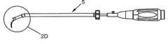
도 2A 및 2C는, 추골 사이에 인터소매틱 케이지를 삽입하기 위한 기구의 일 실시예의 측면을 도시하는데, 여기서 상기 기구의 움켜쥠부는 각각 일직선 및 각진 위치에 있고, 도 2B 및 2D는, 각각의 도 2A 및 2C에서 각각의 원 2B 및 2D로 표시 된 부분을 자세히 도시하며;2A and 2C show aspects of one embodiment of an instrument for inserting an intersociative cage between the vertebrae, wherein the retracted portions of the instrument are in straight and angled positions, respectively, and FIGS. 2B and 2D are respective views Details of the portions indicated by
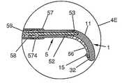
도 3A는 절단면 3B-3B로, 인터소매틱 케이지를 삽입하기 위한 기구의 일 실시예의 평면도이고, 도 3B는 상기 삽입 기구의 이 실시예의 축 3B-3B에 따른 단면도를 도시하고, 도 3C 및 3D는 각각, 도 3B에서 각각의 원 3C 및 3D로 표시된 부분을 자세히 도시하며;3A is a plan view of one embodiment of an instrument for inserting an intersociative cage, with cut surfaces 3B-3B, FIG. 3B shows a cross-sectional view along
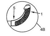
도 4A는 상기 기구의 움켜쥠부에 고정된 인터소매틱 케이지의 삽입 방법으로 인터소매틱 케이지를 삽입하기 위한 기구의 일 실시예의 측면을 도시하고, 도 4B는 도 4A에서 원 4B로 표시된 부분을 자세히 도시하고, 도 4C는 절단면 4D-4D로, 상기 인터소매틱 케이지를 고정하는 기구의 이 실시예의 평면도를 도시하고, 도 4D는 이 실시예의 축 4D-4D에 따른 단면도를 도시하고, 도 4E는 도 4D에서 원 4E로 표시된 부분을 자세히 도시하며;FIG. 4A shows a side view of an embodiment of an instrument for inserting an intersomatic cage in a method of inserting an intersomatic cage secured to a recessed portion of the instrument, and FIG. 4B details the portion labeled
도 5A 및 도 5B는 본 발명에 따른 인터소매틱 케이지의 2개의 다른 실시예의 사시도이고, 도 5C는 본 발명에 따른 인터소매틱 케이지의 또 다른 실시예의 평면도이며;5A and 5B are perspective views of two different embodiments of intersomatic cages in accordance with the present invention, and FIG. 5C is a top view of another embodiment of an intersomatic cage in accordance with the present invention;
도 6A는 본 발명에 따른 인터소매틱 케이지의 또 다른 실시예의 평면도이고, 도 6B 및 6C는 각각, 본 발명의 또 다른 실시예에 따른 앵커의 평면도 및 측면도이다.6A is a top view of yet another embodiment of an intersomatic cage in accordance with the present invention, and FIGS. 6B and 6C are top and side views, respectively, of an anchor according to another embodiment of the present invention.
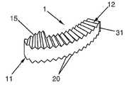
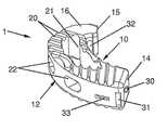
본 발명은 추간 융합 이식편용 경추간공 인터소매틱 케이지에 관한 것이다. 이 케이지는, 인접한 추골의 골 융합 (관절고정술)을 허용하고 성장시키기 위해, 추간판 공간에 이식편이 삽입되도록 하기에 충분한 추간판 공간을 유지하는 데 사용된다. 케이지의 삽입을 담당하는 외과의사의 편의에 따라 어떠한 접근법을 통해서도 상기 케이지를 삽입할 수 있지만, 상기 케이지는 특히 경추간공 접근법을 통해 삽입되는 것에 적합하기 때문에, 상기 케이지를 경추간공이라고 부른다. 이미 공지된 방식에서, 상기 인터소매틱 케이지는 측부 오목면 (10), 측부 볼록면 (11), 일직선 상면 (12), 및 일직선 하면 (13)을 갖는 원호 형태의 몸체 (1)를 갖는다. 따라서, 상기 몸체 (1)는 어느 정도 바나나 또는 단순한 브래킷 형태를 갖고, 실제로 원호를 그린다.The present invention relates to a cervical intervertebral intersomatic cage for intervertebral fusion grafts. This cage is used to maintain sufficient intervertebral disc space to allow the implant to be inserted into the intervertebral disc space to allow and grow bone fusion (articular fixation) of adjacent vertebrae. The cage may be inserted through any approach at the convenience of the surgeon responsible for the insertion of the cage, but the cage is called a cervical intervertebral cavity because it is particularly suitable for being inserted through a cervical intervertebral cavity approach. In a known manner, the intersomatic cage has an arc shaped
본 발명의 다양한 실시예에 따른 케이지의 원호 형태는, 특히 추골 플레이트 (vertebral plate)의 에지 (edge) 형태에 잘 어울리고, 이것은 상기 케이지가 추골 플레이트의 외곽 부근, 즉 그것의 가장 딱딱한 부분에 위치하도록 한다. 따라서, 본 발명의 다양한 실시예에 따른 케이지는, 예를 들어 추골 플레이트의 전방 외곽 부의 높이에서 삽입될 것이다. 또한, 상기 추골 플레이트의 에지에 가까운 상기 케이지의 위치 설정을 통해, 골 이식편 또는 대용물을 위한 큰 초기 면 (initial surface)을 얻을 수 있다. 상기 몸체 (1)의 일 말단에서, 상기 케이지는, 추골 사이에 상기 케이지의 삽입을 위한 기구 (5)의 봉 (53)을 수용하도록 설계된, 단부 구멍이라 불리는, 적어도 하나의 구멍 (30)을 갖는 단부벽 (14)를 포함한다.The arc shape of the cage according to various embodiments of the invention is particularly well suited to the shape of the edges of the vertebral plate, which is such that the cage is located near the periphery of the vertebral plate, ie its hardest part. do. Thus, the cage according to various embodiments of the invention will be inserted at the height of the front outer portion of the vertebral plate, for example. In addition, by positioning the cage close to the edge of the vertebral plate, a large initial surface for the bone graft or surrogate can be obtained. At one end of the
본 발명에 따른 케이지의 특히 이로운 실시예에서, 상기 단부 구멍(30)은 상기 몸체 (1)에 의해 형성된 원호에 어느 정도 접선 배향으로 배향을 갖는다. 상기 몸체 (1)에 의해 형성된 원호에 접선한 상기 단부 구멍 (30)의 이러한 배향으로 인해, 상기 케이지 삽입 기구 (5)가 상기 케이지를 용이하게 뚫고, 상기 단부 구멍 (30)으로 상기 기구 (5)의 봉 (53)의 삽입 및 그것으로부터의 제거가 용이하게 된다. 또한, 상기 단부벽 (14)은, 케이지 삽입 기구 (5)의 적어도 하나의 핀 (54)을 수용하도록 설계된 적어도 하나의 리세스 (31)를 포함한다. 상기 리세스 (31)는, 상기 기구가 상기 케이지를 움켜쥐기 위한 추가 면 (additional surface)을 제공하는 데 사용된다. 그것은 예를 들어, 상기 기구 (5)의 핀 (54)의 세레이션 [따라서, 예를 들어 가시 (spur) 모양을 가짐]가 고정될 수 있는 홈을 지닌 리세스와 같은 더 복잡한 형태의 리세스 또는 단순한 숄더 (shouler)로 이루어질 수 있다.In a particularly advantageous embodiment of the cage according to the invention, the
본 발명에 따른 케이지의 특히 이로운 실시예에서, 상기 몸체 (1)의 단부벽 (14)과 마주보는 말단은, 상기 몸체 (1)에 의해 형성된 원호가 놓인 원의 중심을 향해 상기 몸체 (1)를 연장하는 복귀부 (15)를 포함한다. 상기 복귀부는, 인터소매틱 케이지의 치수를 지나치게 증가시키지 않고, 추골 사이에서 상기 인터소매틱 케이지에 더 높은 안정성을 제공한다. 상기 복귀부는, 상기 인터소매틱 케이지가 환자의 2개의 추골 사이에 삽입될 때 가해지는 응력 작용 하에, 그것의 측면 중 하나로 기울어지는 것을 방지하는 데 사용된다. 또한, 상기 복귀부 (15)는 복귀 구멍이라 불리는 적어도 하나의 구멍 (32)을 포함하는데, 상기 구멍의 배향은 상기 몸체 (1)의 오목면 (10)에 의해 형성된 원호에 어느 정도 접선하고, 케이지 삽입 기구 (5)의 적어도 일 단부 (55)를 수용하도록 설계된다. 따라서, 상기 기구 (5)는 상기 몸체에 의해 형성된 원호의 형태와 상보적인 형태를 갖는 스파튜라 (56)를 포함할 수 있다. 그 결과, 상기 스파튜라 (56)는 상기 몸체 (1)에 끼워맞춰 상기 케이지의 외형을 껴안는다. 상기 스파튜라 (56)의 일 끝단에서, 일 단부 (55)는 상기 복귀 구멍 (32)으로 삽입되도록 설계될 수 있다. 상기 단부 구멍 (30), 리세스 (31) 및 복귀 구멍 (32) 각각을 상기 케이지 삽입 기구 (5)의 봉 (53), 핀 (54) 및 단부 (55)와 함께 끼워맞춤으로써, 상기 봉 (53)의 일 단부가 상기 단부 구멍 (30)에 놓일 때 상기 기구 (5)가 상기 케이지를 잘 움켜쥘 수 있게 한다. 상기 케이지의 가장 원거리 단부까지 완벽히 움켜쥠으로써, 상기 기구 (5)의 끝단에서의 상기 케이지에 뛰어난 안정성을 제공하여 상기 케이지의 삽입이 용이하게 한다. 또한, 이러한 뛰어난 안정성은, 특히 상기 경추간공 접근법을 통해 삽입할 경우 중요하다. 상기 봉 (53)은, 상기 단부 구멍 (30)으로부터 제거될 있도록 상기 기구 (5)에서 미끄러지도록 설계되고, 상기 기구 (5)의 제거 및 상기 케이지의 자유로운 움직임을 허용하도록 설계된다.In a particularly advantageous embodiment of the cage according to the invention, the end facing the
이미 공지된 방식에서, 상기 몸체 (1)의 상면 및 하면 중 적어도 하나는, 케이지가 그 사이에 삽입되는 인접한 추골에 대한 상기 케이지의 움직임을 방해하는 세레이션(20)이 형성된다. 본 발명은 다른 가능한 배향의 세레이션(20)을 제공한다. 이로운 방식으로, 본 발명의 일 실시예에서, 특히 도 1A 내지 1C 도시된 것처럼, 상기 케이지의 2개의 마주보는 면에 존재하는 상기 세레이션(20)은 상기 각각의 면에 대해 다른 방향으로 상기 케이지의 움직임을 방해하기 위하여 동일한 배향을 갖지 않을 수 있다. 또 다른 실시예에서, 특히 도 1D에 도시된 것처럼, 상기 케이지의 2개의 마주보는 면에 존재하는 상기 세레이션(20)은 동일한 배향을 가질 것이다. 마찬가지로, 상기 케이지의 일 면에 존재하는 세레이션(20)은 동일한 면에 위치한 다른 세레이션과 다른 배향을 가질 수 있다. 반대로, 상기 케이지의 소정의 면에 존재하는 모든 세레이션(20)은 동일한 배향을 가질 수 있다. 따라서, 상기 실시예에 따라, 상기 인터소매틱 케이지는 그것의 양쪽 면의 일부 또는 전체에 이러한 배향의 조합 어떤 것도 포함할 수 있다. 상기 몸체 (1)에 의해 형성된 원호 말단은 상기 케이지의 길이방향 축을 형성한다. 상기 케이지는 그것에 수직인 축보다 상기 길이방향 축의 치수가 더 크다. 이러한 길이방향 축은, 상기 세레이션을 다른 가능한 배향으로 형성되도록 할 것이다. 따라서, 일 실시예에서, 특히 도 1C에 도시된 것처럼, 상기 세레이션(20)의 적어도 일부분은 상기 케이지의 길이방향 축에 평행하게 배향되거나, 또는 수직하게 배향될 수 있다. 또 다른 실시예에서, 상기 세레이션(20)은 상기 케이지의 길이방향 축에 대해 0 내지 90도의 각을 형성하도록 배향될 수 있다. 또 다른 실시예에서, 특히 도 1A에 도시된 것처럼, 상기 세레이션(20)의 적어도 일부는, 상기 길이방향 축에 수직인 축에 대해 중심을 둔 역 V자형(chevron)을 그릴 수 있다. 또 다른 실시예에서, 상기 세레이션(20)의 적어도 일부분은, 상기 몸체 (1)에 의해 형성된 원호에 대해, 각각 축대칭 (axial symmetry)으로 동심(concentric) 원호를 그릴 수 있는데, 상기 축대칭의 대칭축은 상기 케이지의 길이 방향 축과 평행하다. 또 다른 실시예에서, 특히 도 1B 및 1D에 도시된 것처럼, 상기 세레이션(20)의 적어도 일부분은, 상기 몸체 (1)에 의해 형성된 원호가 놓인 원에 의해 형성된 반경(radii)과 평행하도록 배향될 것이다.In a known manner, at least one of the upper and lower surfaces of the
또한, 상기 복귀부 (15)는 상기 몸체 (1)의 상면 및 하면이 각각 연장된 상면 및 하면을 포함한다. 또한, 일 실시예에서, 상기 복귀부 (15)의 상면 및 하면 중 적어도 하나는, 상기 케이지의 움직임을 방해하는 세레이션(20)이 형성될 수 있다. 또 다른 실시예에서, 특히 도 1A에 도시된 것처럼, 상기 복귀부 (15)의 상면 및 하면 중 적어도 하나는, 상기 추간판 공간에 상기 케이지의 삽입을 용이하게 하는 적어도 하나의 챔퍼(16)를 포함할 수 있다.In addition, the
상기 도면에 도시된 실시예에서, 상기 케이지 (1)의 상면 및 하면은 일반적으로 평평하고, 상기 상면 및 하면에 의해 형성된 평균 평면은 서로 실질적으로 평행하다. 본 발명의 일부 실시예 (미도시)에서, 상기 케이지 (1)의 상면 및 하면에 의해 형성된 평균 평면은 서로 평행하지 않다. 따라서, 이러한 평면은, 척추의 결손을 교정시키도록 하는 각을 형성할 수 있다 (추골의 배향). 그러한 실시예에서, 상기 케이지 (1)는, 상기 추골 사이에 삽입할 때 척추전만 (lordosis)을 일으킬 수 있다. 몇몇 케이지 (1)가 단일 추간 공간 내에서 함께 사용될 수 있기 때문에, 그들의 상면과 하면 사이에 다른 각을 지닌 케이지 (1)들의 조합 어떤 것도 사용될 수 있기 때문에, 그러한 실시예를 통해, 어떠한 배향으로도 척추 결손을 교정시킬 수 있다.In the embodiment shown in the figure, the upper and lower surfaces of the
본 발명의 일부 실시예에서, 특히 도 5A 내지 5C 및 6A에 도시된 것처럼, 상기 케이지의 적어도 일 면은 적어도 하나의 개방부 (21 또는 22)를 포함한다. 상기 도들에 도시된 것처럼, 상기 케이지 (1)는 그것의 상면 및/또는 하면에 위치한 상기 개방부 (21)를 포함할 수 있고, 또한 그것의 측면 (10, 12) 중 적어도 하나에 상기 개방부 (22)를 포함할 수 있다. 다양한 실시예에서, 상기 개방부 (21, 22)는 막힌 구멍 (blind hole)을 형성할 수 있거나, 또는 상기 케이지의 몸체를 통과하는 도관을 형성할 수 있다. 상기 개방부는, 골 이식편 또는 대용물이 상기 개방부 내부에서 성장할 수 있게 하여 추골에 상기 케이지를 고정시키도록 한다. 따라서, 상기 골 이식편 또는 대용물은 상기 개방부 (12 또는 22) 내부로 삽입될 수 있거나, 또는 단지 상기 추간 공간에 놓여 상기 개방부 내에서 성장할 수 있다. 특히 상기 케이지가 그것의 상면에서 하면으로 연장된 도관을 형성하는 개방부 (21)를 포함할 때, 상기 케이지 (1)가, 도 6A에 도시된 것처럼, 상기 케이지 (1)를 강화 (consolidate)하기 위해 개방부 (21)를 통과하는 가로대 (crosspiece)(23)를 더 포함하는 것이 이로울 수 있다.In some embodiments of the present invention, at least one side of the cage includes at least one
본 발명의 일부 실시예에서, 상기 케이지는, 상기 케이지의 몸체 (1)를 관통하고, 상기 케이지의 적어도 일 면에서 다른 면, 즉 상면 및/또는 하면 및/또는 단부벽 및/또는 오목면 (10) 및/또는 볼록면 (12) 및/또는 상기 복귀부 (15)의 일면으로 연장된 적어도 하나의 슬릿 (33)을 포함한다. 상기 슬릿 (33)은, 예를 들어, 도 5A에 도시된 것처럼, 상기 케이지의 단부벽 (14)에서 상면으로 연장될 수 있고, 도 5B에 도시된 것처럼, 상기 케이지의 볼록면 (12)에서 하면으로도 연장될 수 있다. 이러한 슬릿 (33)은, 추골체에 채워지는 앵커 (anchor)(4)를 수용하기 위한 것이다. 도 6B 및 6C에 도시된 것처럼, 상기 앵커 (4)는 상기 슬릿 (33)에 넣어져서 상기 추골체에 채워지는 실질적으로 직사각형의 평평한 플레이트 (40)를 포함하여, 그 결과 상기 케이지 (1)가 상기 추골에 고정되도록 할 수 있다. 따라서, 상기 슬 릿 (33)은 상기 케이지 (1)의 몸체를 통과하는 도관이고, 상기 앵커 (4)를 수용하도록 맞춰진 직사각형 단면 (section)을 가질 수 있다. 상기 앵커 플레이트 (40)는 추골에 상기 앵커 (4)를 보유하도록 배향된 노치 (notch)(42)를 포함할 수 있다. 변형 실시예에서, 상기 앵커 플레이트 (40)는 그것의 일 단부에, 그것의 상기 추간체의 관통을 용이하게 하기 위한 챔퍼 또는 베빌 (bevel)(도 6C에 도시됨)을 포함할 수 있다. 변형 실시예에서, 상기 챔퍼를 포함할 수 있는 단부와 마주보는 단부에서, 상기 앵커 플레이트 (40)는, 상기 케이지 (1)에 상기 앵커를 고정하기 위한 복귀부 (41)를 포함할 수 있다. 도 6C에 도시된 것처럼, 상기 복귀부 (41)는, 상기 몸체의 일 면에 있는 상기 슬릿 (33)의 개방부 에지에 연동 (interlock)될 수 있는 구부러진 단면으로 이루어진다. 변형 실시예에서, 상기 슬릿 (33)의 에지는, 상기 앵커 (4)의 복귀부 (41)의 연동을 용이하게 하기 위한 홈을 포함할 수 있다. 변형 실시예에서, 상기 앵커 (4)는, 상기 복귀부 (41) 가까이에, 상기 앵커 (4)의 복귀부 (41)를 향해 배향된 가요성 탭 (flexible tab)(43)을 포함한다. 이러한 변형체에서, 상기 가요성 탭 (43)은 상기 앵커 플레이트 (40)의 에지에 반하여 뒤로 접히도록 (fold back) 구성되어, 상기 케이지 (1)의 슬릿 (33)으로 상기 앵커 (4)의 삽입을 허용한다. 상기 앵커 (4)의 이러한 실시예에서, 상기 케이지 (1)의 슬릿 (33)의 내벽 (inner wall)은 상기 가요성 탭 (43)을 수용하고 상기 케이지 (1)에 상기 앵커 (4)를 고정하기 위한 리세스를 포함한다. 이 실시예에서, 상기 앵커 (4)의 복귀부 (41)는, 예를 들어 상기 슬릿이 위치한 케이지의 면과 협동하는 스톱 (stop)을 형성하는 앵커 플레이트 (40)를 단순히 확장하는 것으로 이루어질 수 있다. 선 택된 실시예에 따라, 상기 슬릿 (33)의 배향, 및 즉 그것에 삽입된 앵커 (4)의 배향은 상기 케이지의 상면 또는 하면에 대해 5 내지 85도의 각을 형성할 수 있다. 상기 케이지 (1)는, 유사하거나 다른 각으로, 몇몇 앵커 (4)의 삽입을 위한 몇 개의 슬릿 (33)을 포함할 수 있다. 또한, 본 명세서에 설명된 다양한 실시예의 슬릿 (33) 및 앵커 (4)는, 그것의 형태 (상면과 하면 사이의 각), 또는 개방부 (21 및/또는 22)의 존재 또는 부재와 상관없이, 어떠한 실시예의 케이지 (1)에서도 사용될 수 있다.In some embodiments of the invention, the cage penetrates the
또한 본 발명은 추골 사이에 인터소매틱 케이지를 삽입하기 위한 기구 (5)에 관한 것이다. 본 발명에 따른 기구는, 물론 상기 케이지의 삽입을 담당하는 외과의사에게 편리한 어떠한 접근법에도 사용될 수 있지만, 특히 경추간공 접근법을 통한, 추간 융합 이식편용 인터소매틱 케이지의 삽입에 적합하다. 상기 기구 (5)는, 특히 앞서 설명된 인터소매틱 케이지와 결합하여 사용하기에 적합하도록 설계된다. 본 발명의 일 실시예에 따른 기구 (5)는, 상기 케이지가 상기 기구의 단부에 고정되게 하는, 케이지를 움켜쥐기 위한 말단을 포함하고, 이것을 움켜쥠부라고 부른다. 상기 기구의 움켜쥠부의 반대쪽 상기 기구의 말단은, 외과의사가 상기 기구를 조종할 수 있게 하고, 이것을 조종 단부라고 부른다. 상기 기구 (5)의 움켜쥠부는 가이드 튜브라고 불리는 적어도 하나의 튜브 (52)를 포함한다. 상기 가이드 튜브 (52)의 말단에서, 상기 튜브의 일 에지에 지지 스파튜라라고 불리는 스파튜라 (56)가 장착된다. 상기 스파튜라 (56)는 상기 케이지의 몸체 (1)에 의해 형성된 원호에 적어도 부분적으로 끼워맞춰지도록 설계된 원호 형태를 갖는다. 상기 몸체 (1)의 외형을 껴안음으로써, 상기 스파튜라는 상기 케이지에 견고성 (solidity)을 제공한다. 따라서, 상기 스파튜라는 특히 충격으로부터 상기 케이지를 보호할 것인데, 상기 케이지는 때때로 압력보다 충격에 저항력이 적다. 상기 지지 스파튜라 (56)의 기저부에서, 상기 가이드 튜브 (52)는, 상기 봉 (53)의 일 단부가 상기 케이지의 단부 구멍 (30)에 끼워맞추도록 통과하는 개방부를 포함한다. 이 봉 (53)은 상기 가이드 튜브 (52)에 미끄러지도록 장착되고, 상기 케이지를 움켜쥐도록 하기 위해, 상기 케이지의 단부 구멍 (30)에 삽입되기에 적합한 형태와 치수를 갖는다. 일 실시예에서, 상기 봉 (53)은 상기 기구 (5)의 조종 단부 부근까지 연장된다. 상기 봉 (53)은, 상기 기구 (5)의 적어도 일 에지의 홈 (610)을 통해 돌출되는 적어도 하나의 버튼 (61)을 포함하고, 이 버튼 (61)은 상기 봉 (53)이 미끄러지게 하며, 상기 지지 스파튜라 (56)를 붙들고 있는 가이드 튜브 (52)의 단부에 존재하는 개방부에 대해 상기 봉의 위치를 조정할 수 있게 한다. 이러한 버튼은 상기 봉 (53)의 말단에 위치하는 것이 바람직할 것이고, 그로 인해, 상기 실시예에 따라, 상기 버튼은 상기 기구 (5)의 조종 단부, 또는 원칙적으로는 상기 버튼이 상기 조종 단부와 가까워야만 하는 것이 분명히 더 실용적임에도 불구하고, 상기 기구 (5)의 어느 곳과도 가깝게 위치할 수 있다.The invention also relates to a mechanism (5) for inserting an intersomatic cage between the vertebrae. The instrument according to the invention can, of course, be used in any approach convenient for the surgeon responsible for the insertion of the cage, but is particularly suitable for the insertion of interstitial cages for intervertebral fusion grafts, via the intervertebral intervertebral cavity approach. The
일 실시예에서, 상기 가이드 튜브 (52)는, 상기 지지 스파튜라 (56)가 장착되고 반대편 에지의 단부에서, 상기 케이지의 단부벽 (14)에 존재하는 적어도 하나의 리세스 (31)에 끼워맞추기에 적합한 형태와 치수를 지닌 적어도 하나의 핀 (54)을 포함한다. 이 실시예는, 특히 상기 제공된 케이지의 실시예들 중 하나에 적합하 고, 이로써 상기 기구 (5)가 상기 케이지를 더 잘 움켜쥘 수 있다.In one embodiment, the
일 실시예에서, 상기 지지 스파튜라 (56)는 상기 가이드 튜브 (52)와 마주보는 끝단에서, 상기 케이지의 복귀부 (15)에 존재하는 복귀 구멍이라 불리는 적어도 하나의 구멍 (32)으로 삽입하기에 적당한 형태와 치수를 지닌 적어도 하나의 단부 (55)를 포함한다. 이 실시예는, 특히 복귀부 (15)가 상기 몸체 (1)에 의해 형성된 원호가 놓인 원의 중심을 향해 상기 몸체 (1)를 연장하는 상기 케이지의 실시예들 중 하나에 적합하다. 상기 복귀 구멍 (32)이, 상기 몸체 (1)의 오목면 (10)에 의해 형성된 원호에 어느 정도 접선 방향으로 배향을 갖기 때문에, 그로 인해 원호의 상기 스파튜라 끝단의 단부 (55)는, 특히 상기 복귀 구멍 (32)으로 끼워맞추기에 적합한 형태를 가질 것이다. 상기 설명된 일 실시예에서, 상기 케이지 삽입 기구 (5)의 봉 (53), 핀 (54) 및 단부 (55) 각각을 상기 케이지의 단부 구멍 (30), 리세스 (31) 및 복귀 구멍 (32)에 끼워맞추며, 상기 케이지와 기구를 함께 끼워맞추기 위한 수단들을 결합하여, 상기 봉 (53)의 일 단부가 상기 단부 구멍 (30)에 놓일 때 상기 기구 (5)가 상기 케이지를 잘 움켜쥐도록 하고, 상기 케이지의 삽입을 용이하게 한다.In one embodiment, the
특히 이롭고 상기 경추간공 접근법에 적합한 실시예에서, 상기 가이드 튜브 (52)는, 상기 지지 스파튜라 (56)을 붙들고 있는 단부와 마주보는 단부에서, 상기 기구 (5)의 조종 단부 바로 가까이까지 연장되는, 조준 튜브라고 불리는 튜브 (59)에 대해 피봇하는 이동부 (57)를 포함한다. 상기 이동부 (57)는, 상기 지지 스파튜라 (56)에 의해 형성된 원호의 배향과 어느 정도 평행한 적어도 일 방향으로 피봇 한다. 특히 도 3C에 도시된 것처럼, 상기 이동부 (57)와 조준 튜브 (59)는 함께 볼 및 소켓 결합부 [또는 회전 링크 (swivel link)]를 형성할 수 있고, 이들 중 하나는 볼 또는 구 (sphere)(592) 형태의 일 단부를 갖고, 나머지 하나는 상기 구의 형태 및 치수와 상보적인 형태 및 치수를 지닌 구형 리세스 (spherical recess)(571)라 불리는 소켓을 형성하는 중공 단부 (hollow end)를 갖는다. 도 3C에 도시된 실시예에서, 상기 조준 튜브 (59)의 일 단부는 구 (592)의 형태를 갖고, 상기 가이드 튜브 (52)의 해당 단부는 구형 리세스 (571)를 형성한다. 본 발명의 일 실시예에서, 상기 이동부 (57)와 조준 튜브 (59)에 의해 형성된 볼 및 소켓 연결부에서, 상기 지지 스파튜라 (56)와 동일한 상기 기구 (5) 면에 위치한 상기 구형 리세스 (571)의 적어도 에지 (575)는, 상기 지지 스파튜라 (56)에 의해 형성된 원호의 배향과 적어도 어느 정도 평행한 방향으로 피봇팅하도록 하기 위해, 상기 리세스 (571)의 다른 에지 (576)보다 작게 상기 구를 둘러싼다.In an embodiment which is particularly advantageous and suitable for the cervical intervertebral approach, the
일 실시예에서, 상기 봉 (53)은 구부러지기 쉽고, 상기 볼 및 소켓 결합부를 그것의 중심에서 가로지른다. 상기 구 (592)는, 상기 봉 (53)이 미끄러지게 하는 채널을 그것의 중심에서 갖는다. 이 채널은 상기 지지 스파튜라 (56)와 동일한 상기 기구 (5) 면에 위치한 적어도 그것의 에지에 구멍이 뚫릴 것이다. 따라서, 상기 채널은, 도 2C 및 2D에 도시된 것처럼, 볼 및 소켓 결합부의 피보팅으로 인해 상기 기구 (5)가 그것의 각진 위치에 있을 때조차도, 상기 봉 (53)이 상기 볼 및 소켓 결합부를 통해 미끄러지도록 하는 중공부 (593)를 포함할 것이다.In one embodiment, the
일 실시예에서, 상기 로킹 튜브 (locking tube)(58)는 상기 조준 튜브 (59)에 나사로 고정되고, 상기 로킹 튜브 (58)가 나사로 고정되도록 하는 로킹 링 (locking ring)(60)을 포함한다. 나사고정 (screwing-in)과 나사풀림 (unscrewing)은, 상기 조준 튜브 (59)에 대해 상기 로킹 튜브 (58)가 전후 (forward and backward) 움직이도록 허용한다. 상기 로킹 튜브 (58)의 전방 움직임으로 인해, 당연히 상기 로킹 튜브 (58)가 상기 이동부 (57)와 접촉하고, 그 결과 상기 이동부 (57)의 피보팅을 방지한다. 따라서, 상기 가이드 튜브 (52)는, 상기 가이드 튜브 (52)와 조준 튜브 (59) 사이에 어떤 각도로도, 상기 조준 튜브 (59)에 대해 고정될 수 있다. 또한, 일 실시예에서, 특히 도 3C에 도시된 것처럼, 상기 조준 튜브 (59)에 대해 피봇하는 상기 이동부(57)는 적어도 하나의 세레이션(574)을 포함할 수 있다. 이 세레이션(574)의 존재로 인해, 상기 이동부(57)는, 상기 로킹 튜브(58)와 직접 접촉했을 때보다 더 큰 진폭 (amplitude)으로 피봇하게 된다. 상기 세레이션(574)로 인하여 상기 지지 튜브(52)와 조준 튜브(59) 사이의 각진 부분에 의해 형성된 특정 각을 얻게 된다. 또한, 일 실시예에서, 도 2A 내지 2D에 도시된 바와 같이, 상기 세레이션(574)는, 상기 가이드 튜브(52)가 상기 조준 튜브 (59)와 소정의 각을 형성할 때, 상기 로킹 튜브(58) 일 단부의 일 에지가 상기 세레이션(574)에 고정되도록 설계될 수 있다. 따라서, 상기 세레이션(574)은 상기 기구가 상기 로킹 튜브(58)의 나사고정에 의해 전적으로 움직이지 못하게 될 때까지, 상기 기구의 피보팅을 중단시키고 적어도 일 위치에서 그것을 유지하는 데 사용된다.In one embodiment, the locking
이미 공지된 방식에서, 상기 기구 (5)의 조종 단부는 당연히, 상기 기구 (5)를 조종하고 유효 추력 (thrust)이 상기 기구 (5)에 가해지도록 하여 추골 사이에 상기 케이지의 삽입을 용이하게 하는 손잡이 (62)와 조화를 이룬다.In an already known manner, the steering end of the
상기 언급된 대로, 본 발명에 따른 상기 인터소매틱 케이지와 기구는 특히, 경추간공 접근법을 사용하여 2개의 인접 추골 사이에 상기 케이지를 삽입하는 데 적합한다. 이러한 삽입은 하기 설명된 대로 수행될 수 있지만, 물론 다른 절차상의 변형이 당연히 존재할 수 있고, 외과의사가 예를 들어, 인습적으로 사용된 기법 상의 어떤 변화에 따라 본 명세서에 설명된 기법을 편의상 변경할 수 있다. 특히, 본 발명은, 2개의 인접한 추골의 움직임을 허용하며, 바 (bar)를 움직이지 못하게 하여 함께 연결된 골 앵커 임플란트 (osseous anchor implant)와 함께 사용될 수 있는데, 상기 추골 사이에 상기 케이지는 삽입되거나, 제거되거나 또는 제한되도록 설계된다. 이러한 골 앵커 임플란트는, 예를 들어 본 출원인이 제출한 국제공개공보 제WO02/080788(A1)호, 제WO03/049629(A1)호 및 제WO2005/020829(A1)호에 기재된 것이나, 인접한 추골을 움직이지 못하게 하기 위한 다른 유형의 수단들로 이루어질 수 있다. 인접한 추골을 결합시키는 절차는, 상기 인접한 추골을 움직이지 못하게 하는 데 사용된 수단들에 분명히 나타나기 때문에, 본 명세서에서 설명될 필요가 없다.As mentioned above, the intersomatic cage and the instrument according to the invention are particularly suitable for inserting the cage between two adjacent vertebrae using a cervical interbody cavity approach. Such insertion may be performed as described below, but of course there may be other procedural variations as well, and the surgeon may, for example, change the techniques described herein for convenience according to any changes in the techniques used conventionally. have. In particular, the present invention allows the movement of two adjacent vertebrae and can be used with a osseous anchor implant connected together by immobilizing the bar, between which the cage is inserted or Are designed to be removed, or restricted. Such bone anchor implants are described, for example, in WO02 / 080788 (A1), WO03 / 049629 (A1), and WO2005 / 020829 (A1) filed by the present applicant. It may consist of other types of means for immobilization. The procedure for joining adjacent vertebrae does not need to be described herein because it is evident in the means used to immobilize the adjacent vertebrae.
상기 경추간공 접근법을 통해 삽입하는 동안 사용된 절차만이 본 명세서에서 자세히 설명될 것이고, 특히 상기 경추간공 접근법은 관절 돌기를 우회할 필요가 있다는 사실 때문에, 다른 접근법들에 의한 삽입은 상대적으로 유사하고 간단하다. 물론, 상기 경추간공 접근법을 통한 삽입 절차는, 척주 축 측면으로 적어도 한 번의 절개로 시작한다. 예를 들어 윌츠 (Wiltse) 박사가 설명한 것처럼, 전문 외과의 사에게 잘 공지된 병리학 (path)에 따라, 두 번의 근간 (intermuscular) 절개가 행해지는 것이 바람직할 것이다. 선택된 케이지의 크기에 따라 및/또는 2개의 추골 사이의 공간에 따라, 상기 공 (foramen) 및 추간판 공간으로의 접근을 향상시키기 위해, 상기 관절 돌기의 적어도 일부분을 절제할 수 있다. 이러한 관절 돌기는 상기 케이지의 삽입을 위한 면에 측면으로 절제되는 것이 바람직할 것이다. 만일 관절내 (intra-articular) 이식편이 바람직하다면, 양쪽 측면에서도 가능하지만 적어도 한쪽 측면에서, 상기 관절 돌기의 개방 및 갱생 (avivement)[연골 (cartilage)의 제거]으로도, 적어도 하나의 관절내 이식편을 삽입하게 할 것이다. 2개의 인접한 추골을 움직이지 못하게 하도록 설계된 상기 골 앵커 임플란트의 삽입은, 상기 절차의 이 단계에서 이뤄질 수 있다. 여기서, 바 (bar)에 의해 함께 연결되고, 인접한 추골 각각에 나사로 고정된 상기 골 앵커 임플란트는, 상기 추간판 공간으로의 접근을 용이하게 하기 위해, 제1 후부 연신 (posterior distraction)을 허용한다. 신경뿌리 당김기 (nerve root retractor)[또는 뿌리 스프레더 (spreader)]와 같은 공지된 유형의 도구가, 상기 추골의 뿌리를 보호하는 데 사용될 수 있다. 예를 들어, 가로 (transverse) 관절 돌기 사이에서 상기 판륜 외층 (external layer)의 측면 절개가 상기 추간판 공간으로의 접근을 허용할 것이다. 이미 공지된 방식에서, 예를 들어 서스펜션 타이 (suspension ties)에 의해 고정된, 개방 플랩 (open flap)을 형성하여 다음의 수술을 용이하게 할 것이다. 그런 다음, 외과의사는 핵 및 상기 판륜 내층을 완전히 제거할 것이다. 각진 추간판 클램프 (disc clamp), 큐렛 (curette) 및 줄 (rasp)(직선 및 각진)과 같은 공지된 유형의 다른 도구들은, 상기 추간판 공간을 준비하고, 연골을 손상시키거나 약화시키지 않고, 상기 추골 플레이트로부터 연골을 제거하는 이 단계에서 사용될 것이다.Only the procedure used during insertion through the cervical intervertebral approach will be described in detail herein, in particular because of the fact that the cervical intervertebral approach needs to bypass the articular process, insertion by other approaches is relatively similar and simple. Do. Of course, the insertion procedure through the cervical intervertebral cavity approach begins with at least one incision to the spinal axis side. As described, for example, by Dr. Wiltse, it would be desirable to make two intermuscular incisions, according to a path well known to specialist surgeons. Depending on the size of the cage selected and / or the space between the two vertebrae, at least a portion of the articular protrusion may be excised to improve access to the foramen and intervertebral disc space. Such articular protrusions will preferably be excised laterally on the side for insertion of the cage. If an intra-articular graft is desired, at least one intraarticular graft is possible on both sides, but at least on one side, even with the opening and rehabilitation of the articular process (removal of cartilage). Will insert Insertion of the bone anchor implant, designed to immobilize two adjacent vertebrae, can be done at this stage of the procedure. Here, the bone anchor implants connected together by bars and screwed to each of the adjacent vertebrae allow for a first posterior distraction to facilitate access to the intervertebral disc space. Known types of tools, such as nerve root retractors (or root spreaders), can be used to protect the roots of the vertebrae. For example, a lateral incision of the external layer between transverse articular protrusions will allow access to the intervertebral disc space. In an already known manner, it will form an open flap, for example secured by suspension ties, to facilitate subsequent surgery. The surgeon will then completely remove the nucleus and the annulus inner layer. Other tools of known type such as angled disc clamps, curettes and rasps (straight and angled) prepare the intervertebral space and do not damage or weaken cartilage, This step will be used to remove the cartilage from the plate.
상기 절차의 이 단계에서, 외과의사는 추간판 공간에 확실히 접근할 것이다. 상기 골 앵커 임플란트로 인해, 외과의사가 상기 케이지의 삽입을 용이하게 하기 위해 추골을 벌릴 수 있다. 예를 들어, 외과의사는 척주 축과 평행한 바 (bar)에 의해 함께 연결되고 추골에 나사로 고정된 골 앵커 임플란트를 사용할 것이다. 상기 골 앵커 임플란트는 일반적으로, 길이방향 고정 축을 형성하며 추골로 들어간 나사를 포함한다. 이 단계에서, 상기 골 앵커 임플란트의 길이방향 축들은 서로 평행하지 않고, 척주 전방에서 교차한다. 상기 바의 축과 함께, 이 축들은 역 (inverted) 대문자 A를 형성한다. 그런 다음, 외과의사는 상기 골 앵커 임플란트의 벌림을 조정할 것이다. 이를 위해, 외과의사는, 가능한 많이 상기 골 앵커 임플란트를 벌리기 위해 그것의 헤드 (head)에 스프레더 튜브 (spreader tube)를 위치시키거나, 또는 예를 들어 공지된 유형의 연신 집게 (distraction forcep)를 사용할 수 있다. 예를 들어, 국제공개공보 제WO2005/020829(A1)호에 기재된 것처럼, 이동 헤드 [다축 헤드 (polyaxial head)라고 불림]를 갖는 골 앵커 임플란트의 경우, 외과의사는 이 골 앵커 수단의 헤드를 상기 바에 나사로 고정하여, 척주 축과 평행한 바에 따라 그것의 위치를 고정시킬 것이다. 따라서, 상기 바에 삽입되어 안전하게 고정된 상기 골 앵커 임플란트는, 상기 바에 대한 헤드의 이동성으로 인해, 전방 연신 (anterior distraction)이 수행되도록 할 것이다. 외과의사는, 상기 스프레더 튜브들이 서로를 향해 움직이도록 하기 위해 상기 스프레더 튜브들에 압력을 가하 는데, 이로 인해 그것의 기저부에서 상기 역 대문자 A가 쉽게 열려, 그 결과 상기 A가 대문자 H가 된다. 예를 들어, 국제공개공보 제WO03/049629(A1)호에 기재된 것처럼, 고정 헤드를 갖는 골 앵커 임플란트의 경우, 외과의사는 연신 집게를 사용하여, 상기 바에 상기 골 앵커 수단의 헤드를 나사로 고정시키지 않고 상기 골 앵커 임플란트들 사이에 간격을 유지한다. 국제공개공보 제WO03/049629(A1)호에 기재된 것처럼, 상기 바가, 기저부에 볼 및 소켓 연결부를 갖는 고정용 나사 (fixation screw)로 고정되더라도, 그러한 나사 고정으로 인해, 사실상 상기 바 위의 상기 골 앵커 임플란트의 헤드가 차단될 것이다. 따라서, 외과의사는, 각각의 추골에 나사로 고정된 2개의 골 앵커 임플란트의 헤드 사이에 놓인 연신 집게로 상기 골 앵커 임프란트 사이의 간격을 유지하여야만 한다. 그런 다음, 외과의사는, 상기 스프레더 튜브들이 서로를 향해 움직이도록 하기 위해 상기 스프레더 튜브에 압력을 가하는데, 이로 인해 그것의 기저부에서 상기 역 대문자 A가 쉽게 열려, 그 결과 상기 연신 집게의 존재로 인해 상기 A가 대문자 H로 된다. 이러한 수술은 아마도 여러 번 반복될 수 있을 것이다. 예를 들어, 다축 헤드를 지닌 골 앵커 임플란트의 경우, 상기 바로부터 상기 골 앵커 임플란트의 헤드를 나사로 풀어주고, 상기 스프레더 튜브를 분리하여 상기 헤드를 벌린 다음, 상기 임플란트의 헤드를 나사로 고정하고 상기 스프레더 튜브를 함께 잡아당겨 상기 대문자 H의 발 부분 (feet)을 벌려, 그 결과 전방에서 상기 추간판을 열어 상기 수술을 반복할 수 있다. 이러한 추간판 공간의 전방 개방은 척추전만을 조정하면서 동시에 할 수 있다.At this stage of the procedure, the surgeon will have clear access to the intervertebral space. The bone anchor implant allows the surgeon to open the vertebrae to facilitate insertion of the cage. For example, the surgeon will use a bone anchor implant that is connected together by a bar parallel to the spinal axis and screwed to the spine. The bone anchor implant generally comprises a screw that forms a longitudinal fixation axis and enters the vertebrae. In this step, the longitudinal axes of the bone anchor implants are not parallel to each other and intersect in front of the spinal column. Together with the axis of the bar, these axes form an inverted capital letter A. The surgeon will then adjust the opening of the bone anchor implant. To this end, the surgeon can place a spreader tube in its head to spread the bone anchor implant as much as possible, or use a known type of forging, for example. have. For example, in the case of a bone anchor implant with a moving head (called a polyaxial head), as described in WO2005 / 020829 (A1), the surgeon may attach the head of this bone anchor means to the bar. By screwing, it will fix its position in parallel with the spinal axis. Thus, the bone anchor implant inserted into and secured to the bar will allow anterior distraction to be performed due to the mobility of the head relative to the bar. The surgeon exerts pressure on the spreader tubes to cause the spreader tubes to move towards each other, which easily opens the inverted uppercase letter A at its base, resulting in the letter A being capital letter H. For example, as described in WO 03/049629 (A1), for bone anchor implants having a fixed head, the surgeon may use a drawing forceps to screw the head of the bone anchor means to the bar without screwing it. A gap is maintained between the bone anchor implants. As described in WO 03/049629 (A1), even if the bar is fixed with a fixing screw having a ball and socket connection at its base, due to such screw fixation, in fact the bone on the bar The head of the anchor implant will be blocked. Thus, the surgeon must maintain the spacing between the bone anchor implants with a drawing forceps placed between the heads of two bone anchor implants screwed to each vertebra. The surgeon then exerts pressure on the spreader tube to cause the spreader tubes to move towards each other, thereby easily opening the inverted capital letter A at its base, resulting in the presence of the drawing forceps. A becomes uppercase H. This operation may be repeated many times. For example, in the case of a bone anchor implant with a multi-axis head, unscrew the head of the bone anchor implant from the bar, remove the spreader tube to open the head, and then screw the head of the implant into the spreader. By pulling the tubes together, the feet of the capital letter H are opened, resulting in opening the intervertebral disc from the front and repeating the procedure. This anterior opening of the intervertebral disc space can be done simultaneously while only adjusting the spinal column.
그런 후, 외과의사는, 삽입되도록 설계된 케이지와 동일한 치수를 갖는 실험 용 케이지 (trial cage)를 사용하여, 삽입될 케이지를 선택할 것이다. 실험용 케이지를 상기 기구 (5)에 놓은 다음, 상기 추간판 공간으로 밀어 넣는다. 이것은, 추골 플레이트를 약화 (손상)시키지 않기 위해, 지나친 힘을 주지 않고 이루어져야만 한다. 제거 (extraction) 마슬로뜨 (masselotte)[제거기 (extractor) 또는 제거 마슬로뜨 또는 평형추 (bobweight)]와 같은 공지된 유형의 도구를 사용하여 상기 실험용 케이지를 제거하고, 만족스러운 크기의 케이지를 발견할 때까지 이 수술을 반복할 수 있다.The surgeon will then select a cage to be inserted using a trial cage with the same dimensions as the cage designed to be inserted. The experimental cage is placed in the instrument (5) and then pushed into the intervertebral disc space. This must be done without excessive force in order not to weaken (damage) the vertebral plate. Removal of the laboratory cage using a known type of tool such as extraction masselotte (extractor or removal maslot or bobweight), and the cage of satisfactory size You can repeat this operation until you find it.
그런 다음, 상기 스파튜라 (56)의 단부 (55)를 상기 케이지의 복귀 구멍 (32)으로 삽입하고, 상기 핀 (54)이 상기 단부벽 (14)의 리세스 (31)에 고정될 때까지 상기 스파튜라 (56)에 대해 상기 몸체 (1)의 원호를 움직여, 상기 최종적인 케이지를 상기 삽입 기구 (5)에 놓을 수 있다. 그런 후, 상기 케이지를, 상기 단부 구멍 (30)으로 들어가는 슬라이딩 봉 (sliding rod)(53)으로 상기 기구 (5)에 고정한다. 상기 이동부 (57)로 원위부 (distal part)에서 상기 기구를 교합 (articulation)하여, 상기 인터소매틱 공간에 상기 케이지의 체결을 위한 가장 적합한 각을 발견할 수 있게 된다. 예를 들어 핀 렌치 (pin wrench)와 같은 공지된 유형의 도구로, 상기 나사 링 (threaded ring)(60)을 사용하여 상기 로킹 튜브 (58)를 나사로 고정하여, 상기 각이 고정될 수 있다. 따라서, 상기 기구에 고정되고, 최적의 방식으로 배향된 상기 케이지를 추골 사이에 밀어 넣을 수 있다. 상기 케이지는 원을 그리며, 가능한 전방으로 밀어 넣어지는 것이 바람직할 것이다. 상기 케이지의 위치 설정을 최적화하기 위해, 상기 이동부 (67)에 의해 형성된 교합 각은 밀어 넣어지는 동안 조정될 수 있으며, 이때 상기 로킹 링 (60)으로 상기 각을 정확하게 고정하도록 한다. 그런 다음, 상기 인터소매틱 추간판 공간에서 상기 케이지의 위치 및 배향을, 예를 들어, 휘도 증폭기 (brightness amplifier)와 같은 공지된 유형의 x-레이 기구로 확인할 수 있다. 실제로, 일 실시예에서, 상기 케이지는, 상기 휘도 증폭기에 의해 검출될 적어도 하나의 방사선비투과성 표지자를 포함한다. 그런 다음, 외과의사는 상기 표지자 또는 표지자들의 위치 및 배향에 따라 상기 케이지의 위치 설정을 조정할 수 있다. 상기 케이지가 정확하게 삽입됐을 때, 상기 조종 단부 방향으로 상기 슬라이딩 봉 (53)을 움직여, 상기 기구 (5)로부터 상기 케이지를 풀어줄 것이다. 그런 후, 외과의사는 단지 상기 케이지 (상기 추골 플레이트의 전방 에지 높이에 놓이는 것이 바람직함)와 골수강 (medullary cavity) 사이에 골 이식편 또는 대용물을 위치시켜야만 한다. 이를 위해, 외과의사는 예를 들어, 스파튜라와 같은 공지된 유형의 도구를 사용할 것이다. 그런 다음, 적소 (in place)에 상기 이식편을 유지하기 위해, 상기 판륜 외층에 형성된 플랩을 다시 닫고 봉합할 수 있다. 상기 추골의 결합을 최적화하기 위해, 예를 들어, 뒤가쪽 (posterolateral) 유형의 이식편이 이 단계에서 사용될 수 있다. 그런 다음, 예를 들어 가로 관절 돌기에 상기 이식편을 놓을 것이다. 그런 후 레돈 배출관 (redon drain)이 아마도 적소에 놓일 수 있고, 상기 절개 부분의 피하 (subcutaneous)를 봉합한 후, 피부 봉합을 끝으로, 상기 수술 절차가 종결될 것이다.Then, the
본 발명이, 청구한 바와 같이 본 발명의 범위 및 사상을 벗어나지 않고 여러 다른 특정 형태의 실시예를 허용하고, 본 명세서에 기재된 비-제한적인 실시예의 어떠한 조합도 허용한다는 것은 당업자에게 분명해야만 한다. 따라서, 본 발명의 실시예는 오직 설명을 위한 것으로서 간주되어야 하며, 하기 청구의 범위에 의해 한정된 범위 내에서 변형될 수 있고, 본 발명은 상기 기재된 상세한 설명에 제한되지 않아야만 한다.It should be apparent to those skilled in the art that the present invention allows, as claimed, various other specific forms of embodiment without departing from the scope and spirit of the invention and any combination of the non-limiting embodiments described herein. Accordingly, the embodiments of the present invention should be regarded as illustrative only, and may be modified within the scope defined by the following claims, and the present invention should not be limited to the above detailed description.
Claims (40)
Translated fromKoreanApplications Claiming Priority (3)
| Application Number | Priority Date | Filing Date | Title |
|---|---|---|---|
| FR06/01315 | 2006-02-15 | ||
| FR0601315AFR2897259B1 (en) | 2006-02-15 | 2006-02-15 | INTERSOMATIC TRANSFORAMINAL CAGE WITH INTERBREBAL FUSION GRAFT AND CAGE IMPLANTATION INSTRUMENT |
| PCT/IB2007/000367WO2007093900A2 (en) | 2006-02-15 | 2007-02-15 | Transforaminal intersomatic cage and an instrument for implanting the cage |
Publications (2)
| Publication Number | Publication Date |
|---|---|
| KR20080113029A KR20080113029A (en) | 2008-12-26 |
| KR101358560B1true KR101358560B1 (en) | 2014-02-05 |
Family
ID=37067404
Family Applications (1)
| Application Number | Title | Priority Date | Filing Date |
|---|---|---|---|
| KR1020087022303AExpired - Fee RelatedKR101358560B1 (en) | 2006-02-15 | 2007-02-15 | Transforaminal intersomatic cage and an instrument for implanting the cage |
Country Status (8)
| Country | Link |
|---|---|
| US (6) | US8409288B2 (en) |
| EP (1) | EP1996127B1 (en) |
| JP (1) | JP5172709B2 (en) |
| KR (1) | KR101358560B1 (en) |
| CN (1) | CN101394814B (en) |
| BR (1) | BRPI0707919A2 (en) |
| FR (1) | FR2897259B1 (en) |
| WO (1) | WO2007093900A2 (en) |
Families Citing this family (135)
| Publication number | Priority date | Publication date | Assignee | Title |
|---|---|---|---|---|
| FR2897259B1 (en)* | 2006-02-15 | 2008-05-09 | Ldr Medical Soc Par Actions Si | INTERSOMATIC TRANSFORAMINAL CAGE WITH INTERBREBAL FUSION GRAFT AND CAGE IMPLANTATION INSTRUMENT |
| FR2824261B1 (en) | 2001-05-04 | 2004-05-28 | Ldr Medical | INTERVERTEBRAL DISC PROSTHESIS AND IMPLEMENTATION METHOD AND TOOLS |
| FR2827156B1 (en) | 2001-07-13 | 2003-11-14 | Ldr Medical | VERTEBRAL CAGE DEVICE WITH MODULAR FASTENING |
| FR2846550B1 (en) | 2002-11-05 | 2006-01-13 | Ldr Medical | INTERVERTEBRAL DISC PROSTHESIS |
| EP2113227B1 (en) | 2004-02-04 | 2015-07-29 | LDR Medical | Intervertebral disc prosthesis |
| FR2865629B1 (en) | 2004-02-04 | 2007-01-26 | Ldr Medical | INTERVERTEBRAL DISC PROSTHESIS |
| US7918891B1 (en)* | 2004-03-29 | 2011-04-05 | Nuvasive Inc. | Systems and methods for spinal fusion |
| FR2869528B1 (en) | 2004-04-28 | 2007-02-02 | Ldr Medical | INTERVERTEBRAL DISC PROSTHESIS |
| WO2006058221A2 (en) | 2004-11-24 | 2006-06-01 | Abdou Samy M | Devices and methods for inter-vertebral orthopedic device placement |
| FR2879436B1 (en) | 2004-12-22 | 2007-03-09 | Ldr Medical | INTERVERTEBRAL DISC PROSTHESIS |
| US8992622B2 (en) | 2005-05-06 | 2015-03-31 | Titan Spine, Llc | Interbody spinal implant having a roughened surface topography |
| US8262737B2 (en) | 2005-05-06 | 2012-09-11 | Titan Spine, Llc | Composite interbody spinal implant having openings of predetermined size and shape |
| US11096796B2 (en) | 2005-05-06 | 2021-08-24 | Titan Spine, Llc | Interbody spinal implant having a roughened surface topography on one or more internal surfaces |
| US8585765B2 (en) | 2005-05-06 | 2013-11-19 | Titan Spine, Llc | Endplate-preserving spinal implant having a raised expulsion-resistant edge |
| US8551176B2 (en) | 2005-05-06 | 2013-10-08 | Titan Spine, Llc | Spinal implant having a passage for enhancing contact between bone graft material and cortical endplate bone |
| US9125756B2 (en) | 2005-05-06 | 2015-09-08 | Titan Spine, Llc | Processes for producing regular repeating patterns on surfaces of interbody devices |
| US8814939B2 (en) | 2005-05-06 | 2014-08-26 | Titan Spine, Llc | Implants having three distinct surfaces |
| US8758442B2 (en) | 2005-05-06 | 2014-06-24 | Titan Spine, Llc | Composite implants having integration surfaces composed of a regular repeating pattern |
| US8617248B2 (en) | 2005-05-06 | 2013-12-31 | Titan Spine, Llc | Spinal implant having variable ratios of the integration surface area to the axial passage area |
| US8585766B2 (en) | 2005-05-06 | 2013-11-19 | Titan Spine, Llc | Endplate-preserving spinal implant with an integration plate having durable connectors |
| US9168147B2 (en) | 2005-05-06 | 2015-10-27 | Titan Spine, Llc | Self-deploying locking screw retention device |
| US8758443B2 (en) | 2005-05-06 | 2014-06-24 | Titan Spine, Llc | Implants with integration surfaces having regular repeating surface patterns |
| US8562684B2 (en) | 2005-05-06 | 2013-10-22 | Titan Spine, Llc | Endplate-preserving spinal implant with an integration plate having a roughened surface topography |
| US8591590B2 (en) | 2005-05-06 | 2013-11-26 | Titan Spine, Llc | Spinal implant having a transverse aperture |
| US8585767B2 (en) | 2005-05-06 | 2013-11-19 | Titan Spine, Llc | Endplate-preserving spinal implant with an integration plate having durable connectors |
| US8545568B2 (en)* | 2005-05-06 | 2013-10-01 | Titan Spine, Llc | Method of using instruments and interbody spinal implants to enhance distraction |
| US8562685B2 (en) | 2005-05-06 | 2013-10-22 | Titan Spine, Llc | Spinal implant and integration plate for optimizing vertebral endplate contact load-bearing edges |
| FR2887762B1 (en) | 2005-06-29 | 2007-10-12 | Ldr Medical Soc Par Actions Si | INTERVERTEBRAL DISC PROSTHESIS INSERTION INSTRUMENTATION BETWEEN VERTEBRATES |
| FR2891135B1 (en) | 2005-09-23 | 2008-09-12 | Ldr Medical Sarl | INTERVERTEBRAL DISC PROSTHESIS |
| FR2893838B1 (en) | 2005-11-30 | 2008-08-08 | Ldr Medical Soc Par Actions Si | PROSTHESIS OF INTERVERTEBRAL DISC AND INSTRUMENTATION OF INSERTION OF THE PROSTHESIS BETWEEN VERTEBRATES |
| US8500778B2 (en)* | 2006-02-01 | 2013-08-06 | DePuy Synthes Products, LLC | Interspinous process spacer |
| FR2910267B1 (en) | 2006-12-21 | 2009-01-23 | Ldr Medical Soc Par Actions Si | VERTEBRAL SUPPORT DEVICE |
| US8465546B2 (en) | 2007-02-16 | 2013-06-18 | Ldr Medical | Intervertebral disc prosthesis insertion assemblies |
| FR2916956B1 (en) | 2007-06-08 | 2012-12-14 | Ldr Medical | INTERSOMATIC CAGE, INTERVERTEBRAL PROSTHESIS, ANCHORING DEVICE AND IMPLANTATION INSTRUMENTATION |
| FR2917287B1 (en) | 2007-06-15 | 2010-09-03 | Ldr Medical | INTERVERTEBRAL PROSTHESIS |
| US8088163B1 (en) | 2008-02-06 | 2012-01-03 | Kleiner Jeffrey B | Tools and methods for spinal fusion |
| US8083796B1 (en) | 2008-02-29 | 2011-12-27 | Nuvasive, Inc. | Implants and methods for spinal fusion |
| US8795365B2 (en) | 2008-03-24 | 2014-08-05 | Warsaw Orthopedic, Inc | Expandable devices for emplacement in body parts and methods associated therewith |
| US8216317B2 (en) | 2008-03-31 | 2012-07-10 | Stryker Spine | Spinal implant apparatus and methods |
| US20090270988A1 (en)* | 2008-04-24 | 2009-10-29 | Ranier Limited | Artificial spinal disc implant |
| US20210378834A1 (en) | 2008-05-22 | 2021-12-09 | Spinal Surgical Strategies, Inc., A Nevada Corporation D/B/A Kleiner Device Labs | Spinal fusion cage system with inserter |
| US8361152B2 (en) | 2008-06-06 | 2013-01-29 | Providence Medical Technology, Inc. | Facet joint implants and delivery tools |
| USD853560S1 (en) | 2008-10-09 | 2019-07-09 | Nuvasive, Inc. | Spinal implant insertion device |
| US8545566B2 (en)* | 2008-10-13 | 2013-10-01 | Globus Medical, Inc. | Articulating spacer |
| US9717403B2 (en) | 2008-12-05 | 2017-08-01 | Jeffrey B. Kleiner | Method and apparatus for performing retro peritoneal dissection |
| US8366748B2 (en) | 2008-12-05 | 2013-02-05 | Kleiner Jeffrey | Apparatus and method of spinal implant and fusion |
| US8864654B2 (en) | 2010-04-20 | 2014-10-21 | Jeffrey B. Kleiner | Method and apparatus for performing retro peritoneal dissection |
| US9247943B1 (en) | 2009-02-06 | 2016-02-02 | Kleiner Intellectual Property, Llc | Devices and methods for preparing an intervertebral workspace |
| USD656610S1 (en) | 2009-02-06 | 2012-03-27 | Kleiner Jeffrey B | Spinal distraction instrument |
| TW201031379A (en)* | 2009-02-24 | 2010-09-01 | Univ Nat Yang Ming | The insertion apparatus for aligning cage of intervertebral fusion |
| US8641766B2 (en) | 2009-04-15 | 2014-02-04 | DePuy Synthes Products, LLC | Arcuate fixation member |
| US9408715B2 (en) | 2009-04-15 | 2016-08-09 | DePuy Synthes Products, Inc. | Arcuate fixation member |
| CN105326585B (en) | 2009-09-17 | 2018-12-11 | Ldr控股公司 | Intervertebral implant with extensible bone anchoring element |
| USD723682S1 (en) | 2013-05-03 | 2015-03-03 | Spinal Surgical Strategies, Llc | Bone graft delivery tool |
| US10973656B2 (en) | 2009-09-18 | 2021-04-13 | Spinal Surgical Strategies, Inc. | Bone graft delivery system and method for using same |
| US9060877B2 (en) | 2009-09-18 | 2015-06-23 | Spinal Surgical Strategies, Llc | Fusion cage with combined biological delivery system |
| US20170238984A1 (en) | 2009-09-18 | 2017-08-24 | Spinal Surgical Strategies, Llc | Bone graft delivery device with positioning handle |
| US9186193B2 (en) | 2009-09-18 | 2015-11-17 | Spinal Surgical Strategies, Llc | Fusion cage with combined biological delivery system |
| US9173694B2 (en) | 2009-09-18 | 2015-11-03 | Spinal Surgical Strategies, Llc | Fusion cage with combined biological delivery system |
| US8906028B2 (en) | 2009-09-18 | 2014-12-09 | Spinal Surgical Strategies, Llc | Bone graft delivery device and method of using the same |
| US8685031B2 (en) | 2009-09-18 | 2014-04-01 | Spinal Surgical Strategies, Llc | Bone graft delivery system |
| US9629729B2 (en) | 2009-09-18 | 2017-04-25 | Spinal Surgical Strategies, Llc | Biological delivery system with adaptable fusion cage interface |
| USD750249S1 (en) | 2014-10-20 | 2016-02-23 | Spinal Surgical Strategies, Llc | Expandable fusion cage |
| US10245159B1 (en) | 2009-09-18 | 2019-04-02 | Spinal Surgical Strategies, Llc | Bone graft delivery system and method for using same |
| US9028553B2 (en) | 2009-11-05 | 2015-05-12 | DePuy Synthes Products, Inc. | Self-pivoting spinal implant and associated instrumentation |
| US8764806B2 (en) | 2009-12-07 | 2014-07-01 | Samy Abdou | Devices and methods for minimally invasive spinal stabilization and instrumentation |
| WO2011080535A1 (en) | 2009-12-31 | 2011-07-07 | Lrd Medical | Anchoring device, intervertebral implant and implantation instrument |
| EP2547292B1 (en) | 2010-03-16 | 2019-04-24 | Pinnacle Spine Group, LLC | Ntervertebral implants and graft delivery systems |
| FR2958151B1 (en)* | 2010-04-06 | 2012-04-27 | Hassan Razian | SYSTEM FOR REPLACING AN INTERVERTEBRAL DISC. |
| FR2963230A1 (en)* | 2010-07-27 | 2012-02-03 | Euros Sa | Prosthesis for intervertebral disc located between vertebrae of spinal column of patient, has plates comprising external faces, where one external face comprises ribs that are extended in length along convex curves in opposite directions |
| US8900309B2 (en) | 2010-08-31 | 2014-12-02 | Meditech Spine, Llc | Spinal implants |
| US8425529B2 (en) | 2010-09-30 | 2013-04-23 | Stryker Spine | Instrument for inserting surgical implant with guiding rail |
| US8858637B2 (en) | 2010-09-30 | 2014-10-14 | Stryker Spine | Surgical implant with guiding rail |
| US8603175B2 (en) | 2010-09-30 | 2013-12-10 | Stryker Spine | Method of inserting surgical implant with guiding rail |
| TWI465229B (en) | 2011-02-14 | 2014-12-21 | Wiltrom Co Ltd | Interbody fusion cage |
| US20120277866A1 (en)* | 2011-04-28 | 2012-11-01 | Prakasam Kalluri | Angled Bullet-Nose Banana Cage |
| US8845728B1 (en) | 2011-09-23 | 2014-09-30 | Samy Abdou | Spinal fixation devices and methods of use |
| US9132021B2 (en) | 2011-10-07 | 2015-09-15 | Pioneer Surgical Technology, Inc. | Intervertebral implant |
| US8992619B2 (en) | 2011-11-01 | 2015-03-31 | Titan Spine, Llc | Microstructured implant surfaces |
| US9468536B1 (en) | 2011-11-02 | 2016-10-18 | Nuvasive, Inc. | Spinal fusion implants and related methods |
| US9380932B1 (en) | 2011-11-02 | 2016-07-05 | Pinnacle Spine Group, Llc | Retractor devices for minimally invasive access to the spine |
| US9220542B2 (en)* | 2011-12-13 | 2015-12-29 | Tecomet, Inc | System and method for a lockable polyaxial driver tool |
| US20130226240A1 (en) | 2012-02-22 | 2013-08-29 | Samy Abdou | Spinous process fixation devices and methods of use |
| FR2987256B1 (en) | 2012-02-24 | 2014-08-08 | Ldr Medical | ANCHORING DEVICE FOR INTERVERTEBRAL IMPLANT, INTERVERTEBRAL IMPLANT AND IMPLANTATION INSTRUMENTATION |
| CA2880825C (en) | 2012-03-20 | 2021-03-16 | Titan Spine, Llc | Friction-fit spinal endplate and endplate-preserving method |
| US9198767B2 (en) | 2012-08-28 | 2015-12-01 | Samy Abdou | Devices and methods for spinal stabilization and instrumentation |
| EP2716261A1 (en) | 2012-10-02 | 2014-04-09 | Titan Spine, LLC | Implants with self-deploying anchors |
| US9498349B2 (en) | 2012-10-09 | 2016-11-22 | Titan Spine, Llc | Expandable spinal implant with expansion wedge and anchor |
| US9320617B2 (en) | 2012-10-22 | 2016-04-26 | Cogent Spine, LLC | Devices and methods for spinal stabilization and instrumentation |
| USD731061S1 (en) | 2012-11-28 | 2015-06-02 | Nuvasive, Inc. | Intervertebral implant |
| EP2928418A4 (en) | 2012-12-07 | 2016-12-21 | Providence Medical Tech Inc | Apparatus and method for bone screw deployment |
| US10022245B2 (en) | 2012-12-17 | 2018-07-17 | DePuy Synthes Products, Inc. | Polyaxial articulating instrument |
| WO2014159739A1 (en) | 2013-03-14 | 2014-10-02 | Pinnacle Spine Group, Llc | Interbody implants and graft delivery systems |
| FR3005569B1 (en) | 2013-05-16 | 2021-09-03 | Ldr Medical | VERTEBRAL IMPLANT, VERTEBRAL IMPLANT FIXATION DEVICE AND IMPLANTATION INSTRUMENTATION |
| KR101555317B1 (en) | 2013-09-11 | 2015-10-06 | 주식회사 솔고 바이오메디칼 | Cage having the spike |
| US9283091B2 (en)* | 2013-10-07 | 2016-03-15 | Warsaw Orthopedic, Inc. | Spinal implant system and method |
| CN104644291B (en)* | 2013-11-18 | 2017-12-12 | 宝楠生技股份有限公司 | memory type intervertebral fusion fixation device |
| US10478313B1 (en) | 2014-01-10 | 2019-11-19 | Nuvasive, Inc. | Spinal fusion implant and related methods |
| US9615935B2 (en) | 2014-01-30 | 2017-04-11 | Titan Spine, Llc | Thermally activated shape memory spring assemblies for implant expansion |
| FR3016793B1 (en) | 2014-01-30 | 2021-05-07 | Ldr Medical | ANCHORING DEVICE FOR SPINAL IMPLANT, SPINAL IMPLANT AND IMPLANTATION INSTRUMENTATION |
| KR101632908B1 (en)* | 2014-03-12 | 2016-07-01 | 주식회사 디오메디칼 | Cage assembly for spine interbody fusion |
| FR3020756B1 (en) | 2014-05-06 | 2022-03-11 | Ldr Medical | VERTEBRAL IMPLANT, VERTEBRAL IMPLANT FIXATION DEVICE AND IMPLANT INSTRUMENTATION |
| CN107847249A (en)* | 2015-05-11 | 2018-03-27 | 普罗维登斯医疗技术公司 | Bone screws and implant delivery apparatus |
| US10149710B2 (en)* | 2015-05-11 | 2018-12-11 | Providence Medical Technology, Inc. | Bone screw and implant delivery device |
| US10034768B2 (en)* | 2015-09-02 | 2018-07-31 | Globus Medical, Inc. | Implantable systems, devices and related methods |
| US10857003B1 (en) | 2015-10-14 | 2020-12-08 | Samy Abdou | Devices and methods for vertebral stabilization |
| US10610376B2 (en) | 2015-10-16 | 2020-04-07 | Warsaw Orthopedic, Inc. | Expandable spinal implant system and method |
| USD797290S1 (en) | 2015-10-19 | 2017-09-12 | Spinal Surgical Strategies, Llc | Bone graft delivery tool |
| US10765529B2 (en)* | 2015-12-18 | 2020-09-08 | Ctl Medical Corporation | Articulating intervertebral devices, related tools, systems, and methods |
| US10137006B2 (en) | 2016-01-28 | 2018-11-27 | Warsaw Orthopedic, Inc. | Geared cam expandable interbody implant and method of implanting same |
| FR3048176A1 (en) | 2016-02-26 | 2017-09-01 | Ldr Medical | SPINAL ARTHRODESIS IMPLANT SYSTEM |
| US10485677B2 (en)* | 2016-04-28 | 2019-11-26 | Justin Massengale | Lumbar fusion |
| CN106308982A (en)* | 2016-08-22 | 2017-01-11 | 浙江康慈医疗科技有限公司 | Lumbar interbody fusion cage |
| CN106308981A (en)* | 2016-08-22 | 2017-01-11 | 浙江康慈医疗科技有限公司 | Cervical interbody fusion cage |
| CN106236330B (en)* | 2016-08-22 | 2019-03-05 | 浙江康慈医疗科技有限公司 | Dypass waist Invasive lumbar fusion device |
| US10973648B1 (en) | 2016-10-25 | 2021-04-13 | Samy Abdou | Devices and methods for vertebral bone realignment |
| US10744000B1 (en) | 2016-10-25 | 2020-08-18 | Samy Abdou | Devices and methods for vertebral bone realignment |
| FR3058042B1 (en) | 2016-10-27 | 2021-12-10 | Ldr Medical | EXPANDABLE INTERVERTEBRAL IMPLANT |
| US10238503B2 (en) | 2016-11-01 | 2019-03-26 | Warsaw Orthopedic, Inc. | Expandable spinal implant system with a biased tip and method of using same |
| CN106821556A (en)* | 2017-02-14 | 2017-06-13 | 上海凯利泰医疗科技股份有限公司 | A kind of lumbar fusion cages and its use instrument |
| US10966843B2 (en) | 2017-07-18 | 2021-04-06 | DePuy Synthes Products, Inc. | Implant inserters and related methods |
| US11045331B2 (en) | 2017-08-14 | 2021-06-29 | DePuy Synthes Products, Inc. | Intervertebral implant inserters and related methods |
| WO2019051260A1 (en) | 2017-09-08 | 2019-03-14 | Pioneer Surgical Technology, Inc. | Intervertebral implants, instruments, and methods |
| USD907771S1 (en) | 2017-10-09 | 2021-01-12 | Pioneer Surgical Technology, Inc. | Intervertebral implant |
| US11766339B1 (en) | 2017-10-24 | 2023-09-26 | Omnia Medical, LLC | Multi-material multi-component spinal implant |
| US10736752B1 (en) | 2017-10-24 | 2020-08-11 | Omnia Medical, LLC | Multi-material multi-component spinal implant |
| US10973658B2 (en) | 2017-11-27 | 2021-04-13 | Titan Spine, Inc. | Rotating implant and associated instrumentation |
| US11135070B2 (en) | 2018-02-14 | 2021-10-05 | Titan Spine, Inc. | Modular adjustable corpectomy cage |
| CN109044571A (en)* | 2018-07-06 | 2018-12-21 | 上海纳米技术及应用国家工程研究中心有限公司 | The preparation method and product of half-moon-shaped 3D printing PLGA/ hydroxyapatite waist Invasive lumbar fusion device and application |
| US11179248B2 (en) | 2018-10-02 | 2021-11-23 | Samy Abdou | Devices and methods for spinal implantation |
| US11103360B2 (en) | 2019-03-19 | 2021-08-31 | Robert Woodruff | Spinal fusion cage and method of operation |
| CN110251278B (en)* | 2019-07-05 | 2024-11-12 | 北京爱康宜诚医疗器材有限公司 | Vertebral fusion cage and implantation tools |
| JP6700511B1 (en)* | 2019-08-30 | 2020-05-27 | リーガエース株式会社 | System for guiding interbody spacers between bodies |
| IT202000001195A1 (en)* | 2020-01-22 | 2021-07-22 | Sps S R L | SURGICAL KIT FOR VERTEBRAL STABILIZATION |
| US11166825B1 (en) | 2020-07-01 | 2021-11-09 | Warsaw Orthopedic, Inc. | Spinal implant |
Citations (4)
| Publication number | Priority date | Publication date | Assignee | Title |
|---|---|---|---|---|
| KR20020064879A (en)* | 2000-01-31 | 2002-08-10 | 디퍼이 아크로메드 인코포레이티드 | Spinal fusion implant |
| KR20020071855A (en)* | 1999-10-18 | 2002-09-13 | 스트리케 스피네 | Intervertebral disk prosthesis with toothed surfaces |
| KR100410823B1 (en) | 2002-03-07 | 2003-12-18 | Kyung Won Medical Co Ltd | Inflatable bone junction cage |
| KR20040062409A (en)* | 2002-12-31 | 2004-07-07 | 디퍼이 스파인 인코포레이티드 | Novel banana cage |
Family Cites Families (572)
| Publication number | Priority date | Publication date | Assignee | Title |
|---|---|---|---|---|
| US344683A (en) | 1886-06-29 | Tether-stake | ||
| US1025596A (en) | 1911-10-09 | 1912-05-07 | A L Long | Spike. |
| US1121484A (en) | 1913-12-16 | 1914-12-15 | Joseph D Crites | Spike. |
| US3374786A (en) | 1964-12-15 | 1968-03-26 | George R. Callender Jr. | Fractured bone setting fastener assembly |
| US3948262A (en) | 1969-04-01 | 1976-04-06 | Alza Corporation | Novel drug delivery device |
| SE391122B (en) | 1971-01-25 | 1977-02-07 | Cutter Lab | PROTESTS IN THE FORM OF A SPINE BONIC DISC AND PROCEDURES FOR MANUFACTURE THEREOF |
| US3791380A (en) | 1971-12-13 | 1974-02-12 | G Dawidowski | Method and apparatus of immobilizing a fractured femur |
| US3892232A (en) | 1973-09-24 | 1975-07-01 | Alonzo J Neufeld | Method and apparatus for performing percutaneous bone surgery |
| US3875595A (en) | 1974-04-15 | 1975-04-08 | Edward C Froning | Intervertebral disc prosthesis and instruments for locating same |
| US4009712A (en) | 1975-08-07 | 1977-03-01 | The Sampson Corporation | Fluted hip nail implant system for orthopaedic surgery |
| CH612341A5 (en) | 1976-03-16 | 1979-07-31 | Max Bernhard Ulrich | |
| GB1565178A (en) | 1977-02-24 | 1980-04-16 | Interfix Ltd | Bone screw |
| US4237875A (en) | 1979-02-23 | 1980-12-09 | Towmotor Corporation | Dynamic intramedullary compression nailing |
| CA1146301A (en) | 1980-06-13 | 1983-05-17 | J. David Kuntz | Intervertebral disc prosthesis |
| US4379451A (en) | 1980-11-04 | 1983-04-12 | Getscher Philip E | Intramedullary hip pin and cortical plate |
| JPS57163309A (en) | 1981-04-01 | 1982-10-07 | Olympus Optical Co Ltd | Capsule apparatus for medical use |
| US4494535A (en) | 1981-06-24 | 1985-01-22 | Haig Armen C | Hip nail |
| US4409974A (en) | 1981-06-29 | 1983-10-18 | Freedland Jeffrey A | Bone-fixating surgical implant device |
| FR2519857A1 (en) | 1982-01-19 | 1983-07-22 | Butel Jean | DEVICE FOR OSTEOSYNTHESIS OF THE FRACTURES OF THE END OF THE FEMUR |
| US4432358A (en) | 1982-01-22 | 1984-02-21 | Fixel Irving E | Compression hip screw apparatus |
| US4519100A (en) | 1982-09-30 | 1985-05-28 | Orthopedic Equipment Co. Inc. | Distal locking intramedullary nail |
| US4561432A (en) | 1983-09-15 | 1985-12-31 | Floyd A. Coard, M.D. | Fractured femur fixation system |
| CA1227902A (en) | 1984-04-02 | 1987-10-13 | Raymond G. Tronzo | Fenestrated hip screw and method of augmented internal fixation |
| US4657001A (en) | 1984-07-25 | 1987-04-14 | Fixel Irving E | Antirotational hip screw |
| FR2570594B1 (en) | 1984-09-26 | 1989-02-24 | Kehr Pierre | VERTEBRAL PROSTHESIS, PARTICULARLY FOR CERVICAL VERTEBRES |
| US4612920A (en) | 1984-11-06 | 1986-09-23 | Zimmer, Inc. | Compression hip screw |
| US4632101A (en) | 1985-01-31 | 1986-12-30 | Yosef Freedland | Orthopedic fastener |
| US4721103A (en) | 1985-01-31 | 1988-01-26 | Yosef Freedland | Orthopedic device |
| US4599086A (en) | 1985-06-07 | 1986-07-08 | Doty James R | Spine stabilization device and method |
| US4621629A (en) | 1985-08-12 | 1986-11-11 | Harrington Arthritis Research Center | Compression hip screw |
| US4973333A (en) | 1985-09-20 | 1990-11-27 | Richards Medical Company | Resorbable compressing screw and method |
| DE3534747A1 (en) | 1985-09-28 | 1987-04-09 | Hasselbach Christoph Von | THIGH NECK IMPLANT |
| US4776330A (en) | 1986-06-23 | 1988-10-11 | Pfizer Hospital Products Group, Inc. | Modular femoral fixation system |
| GB8620937D0 (en) | 1986-08-29 | 1986-10-08 | Shepperd J A N | Spinal implant |
| US4787378A (en) | 1986-09-08 | 1988-11-29 | Sodhi Jitendra S | Self-retaining nail for fracture of neck of femur |
| US4969887A (en) | 1986-09-08 | 1990-11-13 | Sodhi Jitendra S | Self-retaining nail kit for repairing a fractured neck of femur |
| DE3637314A1 (en) | 1986-11-03 | 1988-05-11 | Lutz Biedermann | SPACE HOLDER IMPLANT |
| US4759352A (en) | 1986-11-10 | 1988-07-26 | Zimmer, Inc. | Instrument for inserting a locking pin |
| SU1651778A3 (en) | 1986-12-19 | 1991-05-23 | Хута Баильдон, Пшедсембиорство Паньствове (Инопредприятие) | Appliance for ostheosynthesis of fractures of the femoral neck |
| US4834757A (en) | 1987-01-22 | 1989-05-30 | Brantigan John W | Prosthetic implant |
| US4714469A (en) | 1987-02-26 | 1987-12-22 | Pfizer Hospital Products Group, Inc. | Spinal implant |
| US4790303A (en) | 1987-03-11 | 1988-12-13 | Acromed Corporation | Apparatus and method for securing bone graft |
| US4898156A (en) | 1987-05-18 | 1990-02-06 | Mitek Surgical Products, Inc. | Suture anchor |
| CH672589A5 (en) | 1987-07-09 | 1989-12-15 | Sulzer Ag | |
| CH672588A5 (en) | 1987-07-09 | 1989-12-15 | Sulzer Ag | |
| GB8718627D0 (en) | 1987-08-06 | 1987-09-09 | Showell A W Sugicraft Ltd | Spinal implants |
| GB8725921D0 (en) | 1987-11-05 | 1987-12-09 | Precision Proc Textiles Ltd | Treatment of wool |
| DE3741493A1 (en) | 1987-12-08 | 1989-06-22 | Roland Man Druckmasch | Supporting element for holding two adjacent vertebrae |
| US5176681A (en) | 1987-12-14 | 1993-01-05 | Howmedica International Inc. | Intramedullary intertrochanteric fracture fixation appliance and fitting device |
| US4968315A (en) | 1987-12-15 | 1990-11-06 | Mitek Surgical Products, Inc. | Suture anchor and suture anchor installation tool |
| DE3809793A1 (en) | 1988-03-23 | 1989-10-05 | Link Waldemar Gmbh Co | SURGICAL INSTRUMENT SET |
| US4911718A (en) | 1988-06-10 | 1990-03-27 | University Of Medicine & Dentistry Of N.J. | Functional and biocompatible intervertebral disc spacer |
| US5015247A (en) | 1988-06-13 | 1991-05-14 | Michelson Gary K | Threaded spinal implant |
| US5484437A (en) | 1988-06-13 | 1996-01-16 | Michelson; Gary K. | Apparatus and method of inserting spinal implants |
| US6210412B1 (en) | 1988-06-13 | 2001-04-03 | Gary Karlin Michelson | Method for inserting frusto-conical interbody spinal fusion implants |
| US6770074B2 (en) | 1988-06-13 | 2004-08-03 | Gary Karlin Michelson | Apparatus for use in inserting spinal implants |
| US6120502A (en) | 1988-06-13 | 2000-09-19 | Michelson; Gary Karlin | Apparatus and method for the delivery of electrical current for interbody spinal arthrodesis |
| US5772661A (en) | 1988-06-13 | 1998-06-30 | Michelson; Gary Karlin | Methods and instrumentation for the surgical correction of human thoracic and lumbar spinal disease from the antero-lateral aspect of the spine |
| US6123705A (en) | 1988-06-13 | 2000-09-26 | Sdgi Holdings, Inc. | Interbody spinal fusion implants |
| US7452359B1 (en) | 1988-06-13 | 2008-11-18 | Warsaw Orthopedic, Inc. | Apparatus for inserting spinal implants |
| EP0703757B1 (en) | 1988-06-13 | 2003-08-27 | Karlin Technology, Inc. | Apparatus for inserting spinal implants |
| US5609635A (en) | 1988-06-28 | 1997-03-11 | Michelson; Gary K. | Lordotic interbody spinal fusion implants |
| CA1333209C (en) | 1988-06-28 | 1994-11-29 | Gary Karlin Michelson | Artificial spinal fusion implants |
| US4892545A (en) | 1988-07-14 | 1990-01-09 | Ohio Medical Instrument Company, Inc. | Vertebral lock |
| AU624627B2 (en) | 1988-08-18 | 1992-06-18 | Johnson & Johnson Orthopaedics, Inc. | Functional and biocompatible intervertebral disc spacer containing elastomeric material of varying hardness |
| US5545229A (en) | 1988-08-18 | 1996-08-13 | University Of Medicine And Dentistry Of Nj | Functional and biocompatible intervertebral disc spacer containing elastomeric material of varying hardness |
| US4973332A (en) | 1988-09-12 | 1990-11-27 | Hospital For Joint Diseases | Attachment for femur sliding screw plate |
| US4919667A (en) | 1988-12-02 | 1990-04-24 | Stryker Corporation | Implant |
| DE8900121U1 (en) | 1989-01-04 | 1990-02-15 | Mecron Medizinische Produkte Gmbh, 1000 Berlin | Compression screw connection device |
| CA1318469C (en) | 1989-02-15 | 1993-06-01 | Acromed Corporation | Artificial disc |
| DE3911610A1 (en) | 1989-04-08 | 1990-10-18 | Bosch Gmbh Robert | ARTIFICIAL DISC |
| US5098433A (en) | 1989-04-12 | 1992-03-24 | Yosef Freedland | Winged compression bolt orthopedic fastener |
| SE466936B (en) | 1989-04-25 | 1992-05-04 | Branemark Per Ingvar | ANCHORING ELEMENT FOR PROCESSING |
| US5002550A (en) | 1989-06-06 | 1991-03-26 | Mitek Surgical Products, Inc. | Suture anchor installation tool |
| US4946468A (en) | 1989-06-06 | 1990-08-07 | Mitek Surgical Products, Inc. | Suture anchor and suture anchor installation tool |
| US5458638A (en) | 1989-07-06 | 1995-10-17 | Spine-Tech, Inc. | Non-threaded spinal implant |
| US5895427A (en) | 1989-07-06 | 1999-04-20 | Sulzer Spine-Tech Inc. | Method for spinal fixation |
| US5032125A (en) | 1990-02-06 | 1991-07-16 | Smith & Nephew Richards Inc. | Intramedullary hip screw |
| CH681595A5 (en) | 1990-03-19 | 1993-04-30 | Synthes Ag | |
| US5057103A (en) | 1990-05-01 | 1991-10-15 | Davis Emsley A | Compressive intramedullary nail |
| US5342394A (en) | 1990-05-16 | 1994-08-30 | Olympus Optical Co., Ltd. | Apparatus for blocking a vein branch and method of blocking a vein branch |
| US5041116A (en) | 1990-05-21 | 1991-08-20 | Wilson James T | Compression hip screw system |
| CH682300A5 (en) | 1990-12-17 | 1993-08-31 | Synthes Ag | |
| US5192326A (en) | 1990-12-21 | 1993-03-09 | Pfizer Hospital Products Group, Inc. | Hydrogel bead intervertebral disc nucleus |
| RU2004218C1 (en) | 1991-02-15 | 1993-12-15 | Научно-практический центр имплантатов с пам тью формы "Доктор" | Apparatus for spondylosyndesis |
| US5192327A (en) | 1991-03-22 | 1993-03-09 | Brantigan John W | Surgical prosthetic implant for vertebrae |
| US5129901A (en) | 1991-06-10 | 1992-07-14 | Decoste Vern X | Cannulated orthopedic screw |
| FR2678823B1 (en) | 1991-07-11 | 1995-07-07 | Legrand Jean Jacques | DEVICE FOR REINFORCING A LIGAMENT DURING A LIGAMENT PLASTY. |
| US5306307A (en) | 1991-07-22 | 1994-04-26 | Calcitek, Inc. | Spinal disk implant |
| US5242448A (en) | 1991-08-01 | 1993-09-07 | Pettine Kenneth A | Bone probe |
| US5320644A (en) | 1991-08-30 | 1994-06-14 | Sulzer Brothers Limited | Intervertebral disk prosthesis |
| US5207679A (en) | 1991-09-26 | 1993-05-04 | Mitek Surgical Products, Inc. | Suture anchor and installation tool |
| US5344459A (en) | 1991-12-03 | 1994-09-06 | Swartz Stephen J | Arthroscopically implantable prosthesis |
| CA2181674A1 (en) | 1991-12-03 | 1993-10-04 | Theodore V. Benderev | Support structure for supporting and positioning medical equipment |
| GB9125798D0 (en) | 1991-12-04 | 1992-02-05 | Customflex Limited | Improvements in or relating to spinal vertebrae implants |
| US5356410A (en) | 1991-12-13 | 1994-10-18 | Dietmar Pennig | Adjuvant for osteosynthesis in the case of pertrochanteric fracture of the neck of the femur |
| US5217486A (en) | 1992-02-18 | 1993-06-08 | Mitek Surgical Products, Inc. | Suture anchor and installation tool |
| US5306309A (en) | 1992-05-04 | 1994-04-26 | Calcitek, Inc. | Spinal disk implant and implantation kit |
| US5326205A (en) | 1992-05-27 | 1994-07-05 | Anspach Jr William E | Expandable rivet assembly |
| US5501695A (en) | 1992-05-27 | 1996-03-26 | The Anspach Effort, Inc. | Fastener for attaching objects to bones |
| FR2695026B1 (en) | 1992-08-25 | 1994-10-28 | Alexandre Worcel | Device for maintaining compression of a fractured bone. |
| US5246458A (en) | 1992-10-07 | 1993-09-21 | Graham Donald V | Artificial disk |
| DE9216092U1 (en) | 1992-11-26 | 1993-01-14 | S + G Implants GmbH, 2400 Lübeck | Disc-shaped implant for stiffening adjacent vertebral bones |
| US5417699A (en) | 1992-12-10 | 1995-05-23 | Perclose Incorporated | Device and method for the percutaneous suturing of a vascular puncture site |
| JPH06178787A (en) | 1992-12-14 | 1994-06-28 | Shima Yumiko | Centrum spacer with joint, intervertebral cavity measuring device and centrum spacer pattern |
| EP0610837B1 (en) | 1993-02-09 | 2001-09-05 | Acromed Corporation | Spine disc |
| CA2155422C (en) | 1993-02-10 | 2005-07-12 | Stephen D. Kuslich | Spinal stabilization surgical method |
| US5324292A (en) | 1993-02-10 | 1994-06-28 | Zimmer, Inc. | Fracture fixation assembly with selectively removable protrusion |
| US6066175A (en) | 1993-02-16 | 2000-05-23 | Henderson; Fraser C. | Fusion stabilization chamber |
| FR2703580B1 (en) | 1993-03-03 | 1997-10-17 | Gilles Robert | Cervical interbody fusion cage. |
| US5356413A (en) | 1993-03-12 | 1994-10-18 | Mitek Surgical Products, Inc. | Surgical anchor and method for deploying the same |
| US5372599A (en) | 1993-03-12 | 1994-12-13 | Mitek Surgical Products, Inc. | Surgical anchor and method for deploying the same |
| IL105183A (en) | 1993-03-28 | 1996-07-23 | Yehiel Gotfried | Surgical device for connection of fractured bones |
| DE4315757C1 (en) | 1993-05-11 | 1994-11-10 | Plus Endoprothetik Ag | Vertebral implant |
| DE4318700C1 (en) | 1993-06-04 | 1994-11-17 | S & G Implants Gmbh | Implant to stiffen neighboring vertebrae |
| US5505735A (en) | 1993-06-10 | 1996-04-09 | Mitek Surgical Products, Inc. | Surgical anchor and method for using the same |
| DE4417629B4 (en) | 1993-06-24 | 2006-03-16 | SDGI Holdings, Inc., Wilmington | Implant for the replacement of vertebral bodies |
| US5645596A (en) | 1993-07-07 | 1997-07-08 | Asahi Kogaku Kogyo Kabushiki Kaisha | Ceramic vertebrae prosthesis |
| DE4323034C1 (en) | 1993-07-09 | 1994-07-28 | Lutz Biedermann | Placeholders, especially for an intervertebral disc |
| EP0636346A1 (en) | 1993-07-23 | 1995-02-01 | Massimo Santangelo | Device for preventive support of the femur |
| FR2708461B1 (en) | 1993-08-06 | 1995-09-29 | Advanced Technical Fabrication | Interbody implant for spine. |
| DE4327054C1 (en) | 1993-08-12 | 1995-04-13 | Schaefer Micomed Gmbh | Ventral intervertebral implant |
| CA2124651C (en) | 1993-08-20 | 2004-09-28 | David T. Green | Apparatus and method for applying and adjusting an anchoring device |
| US5507754A (en) | 1993-08-20 | 1996-04-16 | United States Surgical Corporation | Apparatus and method for applying and adjusting an anchoring device |
| DE4328690B4 (en) | 1993-08-26 | 2006-08-17 | SDGI Holdings, Inc., Wilmington | Intervertebral implant for vertebral body blocking and implantation instrument for positioning the intervertebral implant |
| US5522898A (en) | 1993-09-16 | 1996-06-04 | Howmedica Inc. | Dehydration of hydrogels |
| US5425772A (en) | 1993-09-20 | 1995-06-20 | Brantigan; John W. | Prosthetic implant for intervertebral spinal fusion |
| BE1007549A3 (en) | 1993-09-21 | 1995-08-01 | Beckers Louis Francois Charles | Implant. |
| FR2710519B1 (en) | 1993-09-29 | 1996-01-05 | Dominique Robine | Lumbar interbody fusion cage (CH). |
| US5443514A (en) | 1993-10-01 | 1995-08-22 | Acromed Corporation | Method for using spinal implants |
| US5397364A (en) | 1993-10-12 | 1995-03-14 | Danek Medical, Inc. | Anterior interbody fusion device |
| FR2711505B1 (en) | 1993-10-25 | 1995-12-29 | Tornier Sa | Device for synthesizing fractures of the upper end of the femur. |
| US5417692A (en) | 1994-01-04 | 1995-05-23 | Goble; E. Marlowe | Bone fixation and fusion system |
| FR2715293B1 (en) | 1994-01-26 | 1996-03-22 | Biomat | Vertebral interbody fusion cage. |
| NL9400210A (en) | 1994-02-10 | 1995-09-01 | Acromed Bv | Implantation device for limiting movements between two vertebrae. |
| US5417712A (en) | 1994-02-17 | 1995-05-23 | Mitek Surgical Products, Inc. | Bone anchor |
| US5458601A (en) | 1994-03-28 | 1995-10-17 | Medical University Of South Carolina | Adjustable ligament anchor |
| CA2551185C (en) | 1994-03-28 | 2007-10-30 | Sdgi Holdings, Inc. | Apparatus and method for anterior spinal stabilization |
| US5489210A (en) | 1994-05-13 | 1996-02-06 | Hanosh; Frederick N. | Expanding dental implant and method for its use |
| IT1265965B1 (en) | 1994-05-20 | 1996-12-16 | Francesco Saverio Santori | ENDOMILLARY DEVICE FOR LONG BONE NAILING. |
| US5571189A (en) | 1994-05-20 | 1996-11-05 | Kuslich; Stephen D. | Expandable fabric implant for stabilizing the spinal motion segment |
| JP3509103B2 (en) | 1994-05-23 | 2004-03-22 | スルザー スパイン−テック インコーポレイテッド | Intervertebral fusion implant |
| US5531792A (en) | 1994-06-14 | 1996-07-02 | Huene; Donald R. | Bone plug fixation assembly, expansible plug assembly therefor, and method of fixation |
| US5478342A (en) | 1994-06-30 | 1995-12-26 | Spinetech, Inc. | Reversible bone screw lock |
| US5980522A (en) | 1994-07-22 | 1999-11-09 | Koros; Tibor | Expandable spinal implants |
| DE9413471U1 (en) | 1994-08-20 | 1995-12-21 | Schäfer micomed GmbH, 73614 Schorndorf | Ventral intervertebral implant |
| DE9413778U1 (en) | 1994-08-26 | 1996-01-04 | Schäfer micomed GmbH, 73614 Schorndorf | Intervertebral implant |
| US5472452A (en) | 1994-08-30 | 1995-12-05 | Linvatec Corporation | Rectilinear anchor for soft tissue fixation |
| US5522845A (en) | 1994-09-27 | 1996-06-04 | Mitek Surgical Products, Inc. | Bone anchor and bone anchor installation |
| US5643321A (en) | 1994-11-10 | 1997-07-01 | Innovasive Devices | Suture anchor assembly and methods |
| US5674296A (en) | 1994-11-14 | 1997-10-07 | Spinal Dynamics Corporation | Human spinal disc prosthesis |
| ES2259169T3 (en) | 1994-12-09 | 2006-09-16 | Sdgi Holdings, Inc. | REPLACEMENT OF ADJUSTABLE VERTEBRAL BODY. |
| US5766252A (en) | 1995-01-24 | 1998-06-16 | Osteonics Corp. | Interbody spinal prosthetic implant and method |
| DE19504867C1 (en) | 1995-02-14 | 1996-02-29 | Harms Juergen | Position retainer for spine |
| US6758849B1 (en) | 1995-02-17 | 2004-07-06 | Sdgi Holdings, Inc. | Interbody spinal fusion implants |
| CN1134810A (en) | 1995-02-17 | 1996-11-06 | 索发默达纳集团股份有限公司 | Improved interbody spinal fusion implants |
| US5860973A (en) | 1995-02-27 | 1999-01-19 | Michelson; Gary Karlin | Translateral spinal implant |
| EP0758874B1 (en) | 1995-03-08 | 2001-08-22 | Synthes AG, Chur | Intervertebral implant |
| US5658335A (en) | 1995-03-09 | 1997-08-19 | Cohort Medical Products Group, Inc. | Spinal fixator |
| US6206922B1 (en) | 1995-03-27 | 2001-03-27 | Sdgi Holdings, Inc. | Methods and instruments for interbody fusion |
| US6245072B1 (en) | 1995-03-27 | 2001-06-12 | Sdgi Holdings, Inc. | Methods and instruments for interbody fusion |
| US5782919A (en) | 1995-03-27 | 1998-07-21 | Sdgi Holdings, Inc. | Interbody fusion device and method for restoration of normal spinal anatomy |
| ES2236792T3 (en) | 1995-03-27 | 2005-07-16 | Sdgi Holdings, Inc. | IMPLANTS OF SPINAL FUSION AND INSTRUMENTS FOR INSERTION AND REVIEW. |
| FR2724312B1 (en) | 1995-04-21 | 1997-09-12 | Alby Albert | INTERSOMATIC SPACER |
| FR2733413B1 (en) | 1995-04-27 | 1997-10-17 | Jbs Sa | CERVICAL CAGE DEVICE FOR PERFORMING INTERSOMATIC ARTHRODESIS |
| US5578035A (en) | 1995-05-16 | 1996-11-26 | Lin; Chih-I | Expandable bone marrow cavity fixation device |
| US5702449A (en) | 1995-06-07 | 1997-12-30 | Danek Medical, Inc. | Reinforced porous spinal implants |
| US6039762A (en) | 1995-06-07 | 2000-03-21 | Sdgi Holdings, Inc. | Reinforced bone graft substitutes |
| FR2736537A1 (en) | 1995-07-12 | 1997-01-17 | Vila Thierry | Intersomatic implant for restoring normal anatomical space between vertebrae, to relieve pressure on nerve roots |
| DE19529605C2 (en) | 1995-08-11 | 1997-10-09 | Bernhard Zientek | Intervertebral implant |
| US5683394A (en) | 1995-09-29 | 1997-11-04 | Advanced Spine Fixation Systems, Inc. | Fusion mass constrainer |
| US5989289A (en) | 1995-10-16 | 1999-11-23 | Sdgi Holdings, Inc. | Bone grafts |
| US5888222A (en) | 1995-10-16 | 1999-03-30 | Sdgi Holding, Inc. | Intervertebral spacers |
| US5782830A (en) | 1995-10-16 | 1998-07-21 | Sdgi Holdings, Inc. | Implant insertion device |
| US6423095B1 (en) | 1995-10-16 | 2002-07-23 | Sdgi Holdings, Inc. | Intervertebral spacers |
| US6143031A (en) | 1995-10-20 | 2000-11-07 | Synthes (U.S.A.) | Intervertebral implant with compressible shaped hollow element |
| KR100415064B1 (en) | 1995-10-20 | 2005-04-06 | 신테스 아게 츄어 | Intervertebral implant |
| JP3621424B2 (en) | 1995-10-20 | 2005-02-16 | ジンテーズ アクチエンゲゼルシャフト クール | Intervertebral implant with cage and rotating body |
| DE19541114A1 (en) | 1995-10-26 | 1997-04-30 | Artos Med Produkte | Intervertebral implant |
| JP3692169B2 (en) | 1995-10-31 | 2005-09-07 | 京セラ株式会社 | Artificial intervertebral spacer |
| CA2242645A1 (en) | 1995-12-08 | 1997-06-12 | Robert S. Bray, Jr. | Anterior stabilization device |
| FR2742653B1 (en) | 1995-12-21 | 1998-02-27 | Colorado | INTERSOMATIC VERTEBRAL CAGE |
| US5766253A (en) | 1996-01-16 | 1998-06-16 | Surgical Dynamics, Inc. | Spinal fusion device |
| US5865845A (en) | 1996-03-05 | 1999-02-02 | Thalgott; John S. | Prosthetic intervertebral disc |
| US5800550A (en) | 1996-03-13 | 1998-09-01 | Sertich; Mario M. | Interbody fusion cage |
| US5976139A (en) | 1996-07-17 | 1999-11-02 | Bramlet; Dale G. | Surgical fastener assembly |
| FR2747034B1 (en) | 1996-04-03 | 1998-06-19 | Scient X | INTERSOMATIC CONTAINMENT AND MERGER SYSTEM |
| US6111164A (en) | 1996-06-21 | 2000-08-29 | Musculoskeletal Transplant Foundation | Bone graft insert |
| DE19628473C1 (en) | 1996-07-15 | 1998-04-23 | Aesculap Ag & Co Kg | Implant to fuse vertebrae |
| US5849004A (en) | 1996-07-17 | 1998-12-15 | Bramlet; Dale G. | Surgical anchor |
| FR2753368B1 (en) | 1996-09-13 | 1999-01-08 | Chauvin Jean Luc | EXPANSIONAL OSTEOSYNTHESIS CAGE |
| US5968098A (en) | 1996-10-22 | 1999-10-19 | Surgical Dynamics, Inc. | Apparatus for fusing adjacent bone structures |
| US20050165483A1 (en) | 2004-01-27 | 2005-07-28 | Ray Eddie F.Iii | Bone grafts |
| WO1998017209A2 (en) | 1996-10-23 | 1998-04-30 | Sdgi Holdings, Inc. | Spinal spacer |
| FR2755844B1 (en) | 1996-11-15 | 1999-01-29 | Stryker France Sa | OSTEOSYNTHESIS SYSTEM WITH ELASTIC DEFORMATION FOR SPINE |
| US6712819B2 (en) | 1998-10-20 | 2004-03-30 | St. Francis Medical Technologies, Inc. | Mating insertion instruments for spinal implants and methods of use |
| ES2297092T3 (en) | 1997-02-11 | 2008-05-01 | Warsaw Orthopedic, Inc. | PREVIOUS CERVICAL PLATE OF UNIQUE BLOCK. |
| US6139550A (en) | 1997-02-11 | 2000-10-31 | Michelson; Gary K. | Skeletal plating system |
| US5861041A (en) | 1997-04-07 | 1999-01-19 | Arthit Sitiso | Intervertebral disk prosthesis and method of making the same |
| US6306170B2 (en) | 1997-04-25 | 2001-10-23 | Tegementa, L.L.C. | Threaded fusion cage anchoring device and method |
| US6045579A (en) | 1997-05-01 | 2000-04-04 | Spinal Concepts, Inc. | Adjustable height fusion device |
| US5897556A (en) | 1997-06-02 | 1999-04-27 | Sdgi Holdings, Inc. | Device for supporting weak bony structures |
| US6033438A (en) | 1997-06-03 | 2000-03-07 | Sdgi Holdings, Inc. | Open intervertebral spacer |
| GB9713330D0 (en) | 1997-06-25 | 1997-08-27 | Bridport Gundry Plc | Surgical implant |
| US6454769B2 (en) | 1997-08-04 | 2002-09-24 | Spinal Concepts, Inc. | System and method for stabilizing the human spine with a bone plate |
| US6146421A (en) | 1997-08-04 | 2000-11-14 | Gordon, Maya, Roberts And Thomas, Number 1, Llc | Multiple axis intervertebral prosthesis |
| US6241771B1 (en) | 1997-08-13 | 2001-06-05 | Cambridge Scientific, Inc. | Resorbable interbody spinal fusion devices |
| FR2767675B1 (en) | 1997-08-26 | 1999-12-03 | Materiel Orthopedique En Abreg | INTERSOMATIC IMPLANT AND ANCILLARY OF PREPARATION SUITABLE FOR ALLOWING ITS POSITION |
| US8291572B2 (en) | 1997-08-27 | 2012-10-23 | Rti Biologics, Inc. | Multi-component cortical bone assembled implant |
| US7048762B1 (en) | 1997-08-27 | 2006-05-23 | Regeneration Technologies, Inc. | Elongated cortical bone implant |
| US20010031254A1 (en) | 1998-11-13 | 2001-10-18 | Bianchi John R. | Assembled implant |
| US6613278B1 (en) | 1998-11-13 | 2003-09-02 | Regeneration Technologies, Inc. | Tissue pooling process |
| US6482584B1 (en) | 1998-11-13 | 2002-11-19 | Regeneration Technologies, Inc. | Cyclic implant perfusion cleaning and passivation process |
| US6652818B1 (en) | 1998-11-13 | 2003-11-25 | Regeneration Technologies, Inc. | Implant sterilization apparatus |
| WO1999009914A1 (en) | 1997-08-27 | 1999-03-04 | University Of Florida Tissue Bank, Inc. | Cortical bone cervical smith-robinson fusion implant |
| US20020138143A1 (en) | 1997-08-27 | 2002-09-26 | Grooms Jamie M. | Cortical bone cervical Smith-Robinson fusion implant |
| US6139579A (en) | 1997-10-31 | 2000-10-31 | Depuy Motech Acromed, Inc. | Spinal disc |
| DE29720022U1 (en) | 1997-11-12 | 1998-01-15 | SCHÄFER micomed GmbH, 73035 Göppingen | Intervertebral implant |
| US6482233B1 (en) | 1998-01-29 | 2002-11-19 | Synthes(U.S.A.) | Prosthetic interbody spacer |
| USRE38614E1 (en) | 1998-01-30 | 2004-10-05 | Synthes (U.S.A.) | Intervertebral allograft spacer |
| RU2177278C2 (en) | 1998-03-31 | 2001-12-27 | Новосибирский научно-исследовательский институт травматологии и ортопедии | Interbody fixative for surgical treatment of lumbar intervertebral osteochondrosis |
| DE19818143A1 (en) | 1998-04-23 | 1999-10-28 | Medinorm Ag | Device for connecting vertebrae of the spine |
| US6679915B1 (en) | 1998-04-23 | 2004-01-20 | Sdgi Holdings, Inc. | Articulating spinal implant |
| US6800093B2 (en) | 1998-05-06 | 2004-10-05 | Cortek, Inc. | Device for spinal fusion |
| US6241769B1 (en) | 1998-05-06 | 2001-06-05 | Cortek, Inc. | Implant for spinal fusion |
| US6258089B1 (en) | 1998-05-19 | 2001-07-10 | Alphatec Manufacturing, Inc. | Anterior cervical plate and fixation system |
| US6251140B1 (en) | 1998-05-27 | 2001-06-26 | Nuvasive, Inc. | Interlocking spinal inserts |
| US6136031A (en) | 1998-06-17 | 2000-10-24 | Surgical Dynamics, Inc. | Artificial intervertebral disc |
| DE19826619A1 (en) | 1998-06-17 | 1999-12-30 | Ulrich Gmbh & Co Kg | Implant for the fusion of two vertebrae |
| US6296664B1 (en) | 1998-06-17 | 2001-10-02 | Surgical Dynamics, Inc. | Artificial intervertebral disc |
| DE69917026T2 (en) | 1998-06-23 | 2004-10-28 | Dimso Distribution Medicale Du Sud Ouest | INTERSOMATIC SPINE IMPLANT WITH ANCHORING ELEMENTS |
| US6063121A (en) | 1998-07-29 | 2000-05-16 | Xavier; Ravi | Vertebral body prosthesis |
| DK1100417T3 (en) | 1998-08-03 | 2004-08-02 | Synthes Ag | Intervertebral allograft spacer |
| US6099531A (en) | 1998-08-20 | 2000-08-08 | Bonutti; Peter M. | Changing relationship between bones |
| FR2782632B1 (en) | 1998-08-28 | 2000-12-29 | Materiel Orthopedique En Abreg | EXPANSIBLE INTERSOMATIC FUSION CAGE |
| FR2783703B1 (en) | 1998-09-24 | 2001-02-09 | Philippe Bauchu | ACETABULAR ANCHOR CAP |
| EP1123069B1 (en) | 1998-10-20 | 2008-02-06 | Synthes GmbH | Strain regulating fusion cage for spinal fusion surgery |
| US6113637A (en) | 1998-10-22 | 2000-09-05 | Sofamor Danek Holdings, Inc. | Artificial intervertebral joint permitting translational and rotational motion |
| US6174311B1 (en) | 1998-10-28 | 2001-01-16 | Sdgi Holdings, Inc. | Interbody fusion grafts and instrumentation |
| US6193757B1 (en) | 1998-10-29 | 2001-02-27 | Sdgi Holdings, Inc. | Expandable intervertebral spacers |
| US6497726B1 (en) | 2000-01-11 | 2002-12-24 | Regeneration Technologies, Inc. | Materials and methods for improved bone tendon bone transplantation |
| FR2787015B1 (en) | 1998-12-11 | 2001-04-27 | Dimso Sa | INTERVERTEBRAL DISC PROSTHESIS WITH COMPRESSIBLE BODY |
| US6206923B1 (en) | 1999-01-08 | 2001-03-27 | Sdgi Holdings, Inc. | Flexible implant using partially demineralized bone |
| US6102950A (en) | 1999-01-19 | 2000-08-15 | Vaccaro; Alex | Intervertebral body fusion device |
| US6113638A (en) | 1999-02-26 | 2000-09-05 | Williams; Lytton A. | Method and apparatus for intervertebral implant anchorage |
| US6241770B1 (en) | 1999-03-05 | 2001-06-05 | Gary K. Michelson | Interbody spinal fusion implant having an anatomically conformed trailing end |
| WO2000054821A1 (en) | 1999-03-16 | 2000-09-21 | Regeneration Technologies, Inc. | Molded implants for orthopedic applications |
| US6059787A (en)* | 1999-04-26 | 2000-05-09 | Allen; Drew | Compression bone staple apparatus and method |
| US6342074B1 (en)* | 1999-04-30 | 2002-01-29 | Nathan S. Simpson | Anterior lumbar interbody fusion implant and method for fusing adjacent vertebrae |
| US7094239B1 (en) | 1999-05-05 | 2006-08-22 | Sdgi Holdings, Inc. | Screws of cortical bone and method of manufacture thereof |
| EP1198208B1 (en) | 1999-05-05 | 2013-07-10 | Warsaw Orthopedic, Inc. | Nested interbody spinal fusion implants |
| AU4988700A (en) | 1999-05-05 | 2000-11-17 | Gary K. Michelson | Spinal fusion implants with opposed locking screws |
| US6607530B1 (en) | 1999-05-10 | 2003-08-19 | Highgate Orthopedics, Inc. | Systems and methods for spinal fixation |
| US6214050B1 (en) | 1999-05-11 | 2001-04-10 | Donald R. Huene | Expandable implant for inter-bone stabilization and adapted to extrude osteogenic material, and a method of stabilizing bones while extruding osteogenic material |
| US6491724B1 (en) | 1999-08-13 | 2002-12-10 | Bret Ferree | Spinal fusion cage with lordosis correction |
| US6419704B1 (en) | 1999-10-08 | 2002-07-16 | Bret Ferree | Artificial intervertebral disc replacement methods and apparatus |
| AU770261B2 (en) | 1999-06-04 | 2004-02-19 | Warsaw Orthopedic, Inc. | Artificial disc implant |
| US6277149B1 (en) | 1999-06-08 | 2001-08-21 | Osteotech, Inc. | Ramp-shaped intervertebral implant |
| US6770096B2 (en) | 1999-07-01 | 2004-08-03 | Spinevision S.A. | Interbody spinal stabilization cage and spinal stabilization method |
| US6936071B1 (en) | 1999-07-02 | 2005-08-30 | Spine Solutions, Inc. | Intervertebral implant |
| FR2795945B1 (en) | 1999-07-09 | 2001-10-26 | Scient X | ANATOMICAL INTERSOMATIC IMPLANT AND GRIPPER FOR SUCH AN IMPLANT |
| US7824445B2 (en) | 1999-07-26 | 2010-11-02 | Ladislau Biro | Corpectomy vertebral body replacement implant system |
| FR2897259B1 (en) | 2006-02-15 | 2008-05-09 | Ldr Medical Soc Par Actions Si | INTERSOMATIC TRANSFORAMINAL CAGE WITH INTERBREBAL FUSION GRAFT AND CAGE IMPLANTATION INSTRUMENT |
| FR2797179B1 (en) | 1999-08-03 | 2002-03-08 | Michel Gau | INTERVERTEBRAL NUCLEAR PROSTHESIS AND SURGICAL IMPLANTATION METHOD |
| US8323341B2 (en) | 2007-09-07 | 2012-12-04 | Intrinsic Therapeutics, Inc. | Impaction grafting for vertebral fusion |
| US7972337B2 (en) | 2005-12-28 | 2011-07-05 | Intrinsic Therapeutics, Inc. | Devices and methods for bone anchoring |
| US6080158A (en) | 1999-08-23 | 2000-06-27 | Lin; Chih-I | Intervertebral fusion device |
| US6231610B1 (en) | 1999-08-25 | 2001-05-15 | Allegiance Corporation | Anterior cervical column support device |
| CN1180751C (en) | 1999-08-27 | 2004-12-22 | 库尔斯恩蒂斯股份公司 | Intervertebral implant |
| US6527773B1 (en) | 1999-10-07 | 2003-03-04 | Osteotech, Inc. | Cervical dowel and insertion tool |
| US6432107B1 (en) | 2000-01-15 | 2002-08-13 | Bret A. Ferree | Enhanced surface area spinal fusion devices |
| US6811567B2 (en) | 1999-10-22 | 2004-11-02 | Archus Orthopedics Inc. | Facet arthroplasty devices and methods |
| US6461359B1 (en) | 1999-11-10 | 2002-10-08 | Clifford Tribus | Spine stabilization device |
| US6592624B1 (en) | 1999-11-24 | 2003-07-15 | Depuy Acromed, Inc. | Prosthetic implant element |
| US6432106B1 (en) | 1999-11-24 | 2002-08-13 | Depuy Acromed, Inc. | Anterior lumbar interbody fusion cage with locking plate |
| US6447512B1 (en) | 2000-01-06 | 2002-09-10 | Spinal Concepts, Inc. | Instrument and method for implanting an interbody fusion device |
| US6893462B2 (en) | 2000-01-11 | 2005-05-17 | Regeneration Technologies, Inc. | Soft and calcified tissue implants |
| US20030023304A1 (en) | 2000-01-11 | 2003-01-30 | Carter Kevin C. | Materials and methods for improved bone tendon bone transplantation |
| US20030097179A1 (en) | 2000-01-11 | 2003-05-22 | Carter Kevin C. | Materials and methods for improved bone tendon bone transplantation |
| US6709458B2 (en) | 2000-02-04 | 2004-03-23 | Gary Karlin Michelson | Expandable push-in arcuate interbody spinal fusion implant with tapered configuration during insertion |
| EP1645248B8 (en) | 2000-02-04 | 2010-06-16 | Warsaw Orthopedic, Inc. | Expandable interbody spinal fusion implant having pivotally attached blocker |
| US6500205B1 (en) | 2000-04-19 | 2002-12-31 | Gary K. Michelson | Expandable threaded arcuate interbody spinal fusion implant with cylindrical configuration during insertion |
| US6814756B1 (en) | 2000-02-04 | 2004-11-09 | Gary K. Michelson | Expandable threaded arcuate interbody spinal fusion implant with lordotic configuration during insertion |
| US6716247B2 (en) | 2000-02-04 | 2004-04-06 | Gary K. Michelson | Expandable push-in interbody spinal fusion implant |
| WO2001078798A1 (en) | 2000-02-10 | 2001-10-25 | Regeneration Technologies, Inc. | Assembled implant |
| US6364375B1 (en) | 2000-02-15 | 2002-04-02 | Ashland Products, Inc. | Apparatus for securing sash window |
| WO2001060235A2 (en) | 2000-02-18 | 2001-08-23 | Fogarty Thomas J M D | Improved device for accurately marking tissue |
| DE10011678B4 (en)* | 2000-03-10 | 2007-07-26 | Richard Wolf Gmbh | Surgical instrument for applying implants |
| KR20030007469A (en)* | 2000-03-22 | 2003-01-23 | 스콜리오 지엠비에취 | Cage-type intervertebral implant |
| AR027685A1 (en) | 2000-03-22 | 2003-04-09 | Synthes Ag | METHOD AND METHOD FOR CARRYING OUT |
| US6579291B1 (en) | 2000-10-10 | 2003-06-17 | Spinalabs, Llc | Devices and methods for the treatment of spinal disorders |
| US6402750B1 (en) | 2000-04-04 | 2002-06-11 | Spinlabs, Llc | Devices and methods for the treatment of spinal disorders |
| US6821298B1 (en) | 2000-04-18 | 2004-11-23 | Roger P. Jackson | Anterior expandable spinal fusion cage system |
| US6350283B1 (en) | 2000-04-19 | 2002-02-26 | Gary K. Michelson | Bone hemi-lumbar interbody spinal implant having an asymmetrical leading end and method of installation thereof |
| FR2808995B1 (en) | 2000-05-18 | 2003-02-21 | Aesculap Sa | INTERSOMATIC CAGE WITH UNIFIED GRAFT |
| EP1284707A4 (en)* | 2000-05-30 | 2003-06-25 | Paul S Lin | Implant for placement between cervical vertebrae |
| US6808537B2 (en) | 2000-07-07 | 2004-10-26 | Gary Karlin Michelson | Expandable implant with interlocking walls |
| US6730127B2 (en) | 2000-07-10 | 2004-05-04 | Gary K. Michelson | Flanged interbody spinal fusion implants |
| FR2811543B1 (en) | 2000-07-12 | 2003-07-04 | Spine Next Sa | INTERSOMATIC IMPLANT |
| US6447546B1 (en) | 2000-08-11 | 2002-09-10 | Dale G. Bramlet | Apparatus and method for fusing opposing spinal vertebrae |
| US6458159B1 (en) | 2000-08-15 | 2002-10-01 | John S. Thalgott | Disc prosthesis |
| US20020119437A1 (en) | 2000-09-20 | 2002-08-29 | Grooms Jamie M. | Method of preparing and processing transplant tissue |
| ATE334644T1 (en) | 2000-10-11 | 2006-08-15 | Michael D Mason | INTEGRATED FUSION DEVICE |
| US6723128B2 (en) | 2000-10-17 | 2004-04-20 | Chang Jong Uk | Prosthetic device for correcting deformity of spine |
| US6733531B1 (en) | 2000-10-20 | 2004-05-11 | Sdgi Holdings, Inc. | Anchoring devices and implants for intervertebral disc augmentation |
| US6648893B2 (en) | 2000-10-27 | 2003-11-18 | Blackstone Medical, Inc. | Facet fixation devices |
| JP4130126B2 (en) | 2000-10-27 | 2008-08-06 | ウォーソー・オーソペディック・インコーポレーテッド | Annulus repair system and method |
| AU2002225831A1 (en)* | 2000-11-03 | 2002-05-15 | Osteotech, Inc. | Spinal intervertebral implant and method of making |
| US20050080486A1 (en) | 2000-11-29 | 2005-04-14 | Fallin T. Wade | Facet joint replacement |
| US6579319B2 (en) | 2000-11-29 | 2003-06-17 | Medicinelodge, Inc. | Facet joint replacement |
| US6419703B1 (en) | 2001-03-01 | 2002-07-16 | T. Wade Fallin | Prosthesis for the replacement of a posterior element of a vertebra |
| US6565605B2 (en) | 2000-12-13 | 2003-05-20 | Medicinelodge, Inc. | Multiple facet joint replacement |
| US6365880B1 (en)* | 2000-12-19 | 2002-04-02 | Delphi Technologies, Inc. | Heater patterns for planar gas sensors |
| US6743257B2 (en) | 2000-12-19 | 2004-06-01 | Cortek, Inc. | Dynamic implanted intervertebral spacer |
| US6520993B2 (en) | 2000-12-29 | 2003-02-18 | Depuy Acromed, Inc. | Spinal implant |
| US6972019B2 (en) | 2001-01-23 | 2005-12-06 | Michelson Gary K | Interbody spinal implant with trailing end adapted to receive bone screws |
| DE60224850T2 (en) | 2001-02-04 | 2009-01-22 | Warsaw Orthopedic, Inc., Warsaw | Instrumentation for introducing and positioning an expandable intervertebral fusion implant |
| US6576017B2 (en) | 2001-02-06 | 2003-06-10 | Sdgi Holdings, Inc. | Spinal implant with attached ligament and methods |
| US6740117B2 (en) | 2001-02-15 | 2004-05-25 | Spinecore, Inc. | Intervertebral spacer device having a radially thinning slotted belleville spring |
| US6669730B2 (en) | 2001-02-15 | 2003-12-30 | Spinecore, Inc. | Intervertebral spacer device utilizing a spirally slotted belleville washer having radially extending grooves |
| US6673113B2 (en) | 2001-10-18 | 2004-01-06 | Spinecore, Inc. | Intervertebral spacer device having arch shaped spring elements |
| US6572619B2 (en) | 2001-02-23 | 2003-06-03 | Albert N. Santilli | Cage plate for spinal fusion and method of operation |
| US7090698B2 (en) | 2001-03-02 | 2006-08-15 | Facet Solutions | Method and apparatus for spine joint replacement |
| US6849093B2 (en) | 2001-03-09 | 2005-02-01 | Gary K. Michelson | Expansion constraining member adapted for use with an expandable interbody spinal fusion implant and method for use thereof |
| US6540753B2 (en) | 2001-03-23 | 2003-04-01 | Howmedica Osteonics Corp. | Instrumentation for implant insertion |
| US7128760B2 (en) | 2001-03-27 | 2006-10-31 | Warsaw Orthopedic, Inc. | Radially expanding interbody spinal fusion implants, instrumentation, and methods of insertion |
| US6890355B2 (en) | 2001-04-02 | 2005-05-10 | Gary K. Michelson | Artificial contoured spinal fusion implants made of a material other than bone |
| US6749636B2 (en) | 2001-04-02 | 2004-06-15 | Gary K. Michelson | Contoured spinal fusion implants made of bone or a bone composite material |
| DE10116412C1 (en) | 2001-04-02 | 2003-01-16 | Ulrich Gmbh & Co Kg | Implant to be inserted between the vertebral body of the spine |
| FR2822674B1 (en)* | 2001-04-03 | 2003-06-27 | Scient X | STABILIZED INTERSOMATIC MELTING SYSTEM FOR VERTEBERS |
| FR2823095B1 (en) | 2001-04-06 | 2004-02-06 | Ldr Medical | RACHIS OSTEOSYNTHESIS DEVICE AND PLACEMENT METHOD |
| JP3629557B2 (en) | 2001-04-28 | 2005-03-16 | 李 春澤 | Spinal fusion transfer |
| US20030149438A1 (en)* | 2001-04-30 | 2003-08-07 | Howmedica Osteonics Corp. | Insertion instrument |
| US6719794B2 (en)* | 2001-05-03 | 2004-04-13 | Synthes (U.S.A.) | Intervertebral implant for transforaminal posterior lumbar interbody fusion procedure |
| TW571720U (en)* | 2001-05-04 | 2004-01-11 | Chih-I Lin | Spine fastener with support component |
| FR2824261B1 (en) | 2001-05-04 | 2004-05-28 | Ldr Medical | INTERVERTEBRAL DISC PROSTHESIS AND IMPLEMENTATION METHOD AND TOOLS |
| US6558424B2 (en) | 2001-06-28 | 2003-05-06 | Depuy Acromed | Modular anatomic fusion device |
| FR2827156B1 (en) | 2001-07-13 | 2003-11-14 | Ldr Medical | VERTEBRAL CAGE DEVICE WITH MODULAR FASTENING |
| US6468310B1 (en) | 2001-07-16 | 2002-10-22 | Third Millennium Engineering, Llc | Intervertebral spacer device having a wave washer force restoring element |
| US6527806B2 (en) | 2001-07-16 | 2003-03-04 | Third Millennium Engineering, Llc | Intervertebral spacer device having a spiral wave washer force restoring element |
| US7018412B2 (en)* | 2001-08-20 | 2006-03-28 | Ebi, L.P. | Allograft spinal implant |
| EP1437989A2 (en) | 2001-08-27 | 2004-07-21 | James C. Thomas, Jr. | Expandable implant for partial disc replacement and reinforcement of a disc partially removed in a discectomy and for reduction and maintenance of alignment of cancellous bone fractures and methods and apparatuses for same. |
| US6635087B2 (en) | 2001-08-29 | 2003-10-21 | Christopher M. Angelucci | Laminoplasty implants and methods of use |
| FR2831048B1 (en) | 2001-10-18 | 2004-09-17 | Ldr Medical | PROGRESSIVE APPROACH OSTEOSYNTHESIS DEVICE AND PRE-ASSEMBLY PROCESS |
| FR2831049B1 (en) | 2001-10-18 | 2004-08-13 | Ldr Medical | PLATE FOR OSTEOSYNTHESIS DEVICE AND PRE-ASSEMBLY METHOD |
| FR2831796B1 (en) | 2001-11-06 | 2003-12-26 | Ldr Medical | BONE ANCHORING DEVICE FOR PROSTHESIS |
| EP1454078A2 (en) | 2001-11-13 | 2004-09-08 | Dan Stoianovici | Ball-worm transmission |
| FR2833151B1 (en) | 2001-12-12 | 2004-09-17 | Ldr Medical | BONE ANCHORING IMPLANT WITH POLYAXIAL HEAD |
| US7833255B2 (en) | 2001-12-27 | 2010-11-16 | Osteotech, Inc. | Bone fasteners and method for stabilizing vertebral bone facets using the bone fasteners |
| US6736850B2 (en) | 2001-12-28 | 2004-05-18 | Spinal Concepts, Inc. | Vertebral pseudo arthrosis device and method |
| US6740118B2 (en) | 2002-01-09 | 2004-05-25 | Sdgi Holdings, Inc. | Intervertebral prosthetic joint |
| US6923830B2 (en) | 2002-02-02 | 2005-08-02 | Gary K. Michelson | Spinal fusion implant having deployable bone engaging projections |
| FR2835739B1 (en) | 2002-02-11 | 2004-05-14 | Spinevision | SYSTEM FOR FIXING A WORKPIECE ON A BONE BODY |
| AR038680A1 (en)* | 2002-02-19 | 2005-01-26 | Synthes Ag | INTERVERTEBRAL IMPLANT |
| FR2836373B1 (en)* | 2002-02-26 | 2005-03-25 | Materiel Orthopedique En Abreg | CONNECTING INTERSOMATIC IMPLANTS FOR INSERTING BONE GRAFT FOR REALIZING INTERVERTEBRAL FUSION, INSTRUMENTS FOR CONNECTING THESE IMPLANTS |
| US6682563B2 (en) | 2002-03-04 | 2004-01-27 | Michael S. Scharf | Spinal fixation device |
| EP1482877B1 (en) | 2002-03-11 | 2007-05-30 | Spinal Concepts Inc. | Instrumentation for implanting spinal implant devices |
| US6695846B2 (en) | 2002-03-12 | 2004-02-24 | Spinal Innovations, Llc | Bone plate and screw retaining mechanism |
| US7309358B2 (en) | 2002-03-21 | 2007-12-18 | Warsaw Orthopedic, Inc. | Vertebral body and disc space replacement devices |
| US20030187509A1 (en) | 2002-04-01 | 2003-10-02 | Lemole G. Michael | Modulus plating system and method |
| US7223289B2 (en) | 2002-04-16 | 2007-05-29 | Warsaw Orthopedic, Inc. | Annulus repair systems and techniques |
| US7338525B2 (en) | 2002-04-30 | 2008-03-04 | Ferree Bret A | Methods and apparatus for preventing the migration of intradiscal devices |
| US20050143825A1 (en) | 2002-07-09 | 2005-06-30 | Albert Enayati | Intervertebral prosthesis |
| US20040010312A1 (en) | 2002-07-09 | 2004-01-15 | Albert Enayati | Intervertebral prosthesis |
| EP1542626B1 (en) | 2002-08-15 | 2012-09-26 | Synthes GmbH | Controlled artificial intervertebral disc implant |
| CA2495404C (en) | 2002-08-15 | 2011-05-03 | Justin K. Coppes | Intervertebral disc implant |
| JP4088495B2 (en) | 2002-08-20 | 2008-05-21 | 昭和医科工業株式会社 | Intervertebral cage |
| DE10247762A1 (en) | 2002-10-14 | 2004-04-22 | Waldemar Link (Gmbh & Co.) | Intervertebral prosthesis |
| DE10248170A1 (en) | 2002-10-16 | 2004-04-29 | Advanced Medical Technologies Ag | Implant for insertion between vertebras of a spinal column comprises two sides whose outer surfaces at the start of a vertebra spreading process converge towards the free ends of the sides |
| DE10248171A1 (en) | 2002-10-16 | 2004-05-13 | Advanced Medical Technologies Ag | Implant for placement between vertebrae of the spine |
| US7232463B2 (en) | 2002-10-23 | 2007-06-19 | U.S. Spinal Technologies, Llc | Intervertebral cage designs |
| US7931674B2 (en) | 2005-03-21 | 2011-04-26 | Kyphon Sarl | Interspinous process implant having deployable wing and method of implantation |
| FR2846550B1 (en) | 2002-11-05 | 2006-01-13 | Ldr Medical | INTERVERTEBRAL DISC PROSTHESIS |
| US6685742B1 (en) | 2002-11-12 | 2004-02-03 | Roger P. Jackson | Articulated anterior expandable spinal fusion cage system |
| FR2846876B1 (en) | 2002-11-12 | 2005-07-29 | Hassan Razian | INTERVENIAL CAGE WITH MEDIAN ANCHOR BLADE |
| US7204852B2 (en) | 2002-12-13 | 2007-04-17 | Spine Solutions, Inc. | Intervertebral implant, insertion tool and method of inserting same |
| DE50212249D1 (en) | 2002-12-17 | 2008-06-19 | Synthes Gmbh | INTERMEDIATE IMPLANT WITH TILTING JOINT PARTS |
| FR2848408B1 (en) | 2002-12-17 | 2005-08-19 | Vitatech | DEVICE WITH ANTERIOR PLATE FOR MAINTAINING THE RACHIS |
| AU2002347119B2 (en) | 2002-12-17 | 2007-01-25 | Synthes Gmbh | Intervertebral implant |
| JP4276625B2 (en) | 2002-12-17 | 2009-06-10 | ジンテーズ ゲゼルシャフト ミト ベシュレンクテル ハフツング | Intervertebral implants with joints arranged in a cardan fashion |
| AU2003297195A1 (en) | 2002-12-17 | 2004-07-22 | Amedica Corporation | Total disc implant |
| US7473276B2 (en) | 2002-12-17 | 2009-01-06 | Synthes (U.S.A.) | Intervertebral implant with joint parts mounted on roller bodies |
| US7582107B2 (en)* | 2003-02-03 | 2009-09-01 | Integra Lifesciences Corporation | Compression screw apparatuses, systems and methods |
| CA2515247C (en) | 2003-02-06 | 2010-10-05 | Synthes (U.S.A.) | Intervertebral implant |
| US7235101B2 (en) | 2003-09-15 | 2007-06-26 | Warsaw Orthopedic, Inc. | Revisable prosthetic device |
| US20050049590A1 (en) | 2003-03-07 | 2005-03-03 | Neville Alleyne | Spinal implant with securement spikes |
| US7819903B2 (en) | 2003-03-31 | 2010-10-26 | Depuy Spine, Inc. | Spinal fixation plate |
| US7060097B2 (en) | 2003-03-31 | 2006-06-13 | Depuy Spine, Inc. | Method and apparatus for implant stability |
| NZ543434A (en) | 2003-04-11 | 2007-04-27 | Synthes Gmbh | Anchoring means for intervertebral implants, with locking means for minimal operating time |
| US8613772B2 (en)* | 2003-04-21 | 2013-12-24 | Rsb Spine Llc | Lateral mount implant device |
| US9278009B2 (en) | 2003-04-21 | 2016-03-08 | Rsb Spine Llc | Spine implants |
| US6984234B2 (en) | 2003-04-21 | 2006-01-10 | Rsb Spine Llc | Bone plate stabilization system and method for its use |
| US7985255B2 (en) | 2003-04-21 | 2011-07-26 | Rsb Spine Llc | Implant subsidence control |
| US7491204B2 (en) | 2003-04-28 | 2009-02-17 | Spine Solutions, Inc. | Instruments and method for preparing an intervertebral space for receiving an artificial disc implant |
| DE10323368B3 (en) | 2003-05-21 | 2004-08-19 | Corus Bausysteme Gmbh | Support system for attaching building roof or wall cladding panels to sub-structure has support elements for cladding panels locked to support rails by relative rotation |
| DE10323363A1 (en) | 2003-05-21 | 2004-12-09 | Ulrich Gmbh & Co. Kg | Implant for insertion between elements of the vertebral column comprises a hinge which consist of a socket plate and a head element, and is located between the hinge cover plates |
| WO2004105655A1 (en) | 2003-06-02 | 2004-12-09 | Impliant Ltd. | Spinal disc prosthesis |
| US7905886B1 (en) | 2003-07-07 | 2011-03-15 | Nuvasive Inc. | System and methods for performing transforaminal lumbar interbody fusion |
| US20060186063A1 (en) | 2003-07-07 | 2006-08-24 | Wallcrown Limited | System for displaying wallpaper samples |
| DE602004023039D1 (en) | 2003-07-23 | 2009-10-22 | Ebi Llc | Expandable intervertebral implant |
| US7022138B2 (en) | 2003-07-31 | 2006-04-04 | Mashburn M Laine | Spinal interbody fusion device and method |
| US7153325B2 (en) | 2003-08-01 | 2006-12-26 | Ultra-Kinetics, Inc. | Prosthetic intervertebral disc and methods for using the same |
| US7806932B2 (en)* | 2003-08-01 | 2010-10-05 | Zimmer Spine, Inc. | Spinal implant |
| FR2858546B1 (en) | 2003-08-04 | 2006-04-28 | Spine Next Sa | INTERVERTEBRAL DISC PROSTHESIS |
| US7235082B2 (en) | 2003-08-12 | 2007-06-26 | Depuy Spine, Inc. | Device for insertion of implants |
| US20050038511A1 (en) | 2003-08-15 | 2005-02-17 | Martz Erik O. | Transforaminal lumbar interbody fusion (TLIF) implant, surgical procedure and instruments for insertion of spinal implant in a spinal disc space |
| FR2859095B1 (en) | 2003-09-01 | 2006-05-12 | Ldr Medical | BONE ANCHORING IMPLANT WITH A POLYAXIAL HEAD AND METHOD OF PLACING THE IMPLANT |
| FR2860701B1 (en) | 2003-10-09 | 2006-01-06 | Ldr Medical | DEVICE AND METHOD FOR SECTIONING THE BLADE OF A VERTEBRA |
| FR2861582B1 (en) | 2003-10-29 | 2006-02-10 | Eurosurgical | INTERSOMATIC CAGE FOR LUMBAR FUSION FIRST TRANSFORAMINAL AND CAGE HOLDER DEVICE |
| US7217293B2 (en) | 2003-11-21 | 2007-05-15 | Warsaw Orthopedic, Inc. | Expandable spinal implant |
| US6955691B2 (en) | 2003-11-21 | 2005-10-18 | Kyungwon Medical Co., Ltd. | Expandable interfusion cage |
| US7217291B2 (en) | 2003-12-08 | 2007-05-15 | St. Francis Medical Technologies, Inc. | System and method for replacing degenerated spinal disks |
| US7588600B2 (en) | 2003-12-10 | 2009-09-15 | Axiomed Spine Corporation | Method for replacing a damaged spinal disc |
| US7588590B2 (en) | 2003-12-10 | 2009-09-15 | Facet Solutions, Inc | Spinal facet implant with spherical implant apposition surface and bone bed and methods of use |
| DE20320454U1 (en) | 2003-12-22 | 2004-10-14 | Meisel, Hans Jörg, Dr. med. | Component for a prosthesis, especially a cervica vertebra, comprises two base parts coupled together by a hinge |
| FR2864763B1 (en) | 2004-01-07 | 2006-11-24 | Scient X | PROSTHETIC DISCALE FOR VERTEBRATES |
| EP2113227B1 (en) | 2004-02-04 | 2015-07-29 | LDR Medical | Intervertebral disc prosthesis |
| FR2865629B1 (en) | 2004-02-04 | 2007-01-26 | Ldr Medical | INTERVERTEBRAL DISC PROSTHESIS |
| US7850733B2 (en) | 2004-02-10 | 2010-12-14 | Atlas Spine, Inc. | PLIF opposing wedge ramp |
| US7211112B2 (en) | 2004-02-10 | 2007-05-01 | Atlas Spine | Spinal fusion device |
| US7993373B2 (en) | 2005-02-22 | 2011-08-09 | Hoy Robert W | Polyaxial orthopedic fastening apparatus |
| EP1570813A1 (en) | 2004-03-05 | 2005-09-07 | Cervitech, Inc. | Cervical intervertebral disc prosthesis with anti-luxation means, and instrument |
| US7799053B2 (en) | 2004-03-08 | 2010-09-21 | Warsaw Orthopedic, Inc. | Occipital and cervical stabilization systems and methods |
| US8070816B2 (en) | 2004-03-29 | 2011-12-06 | 3Hbfm, Llc | Arthroplasty spinal prosthesis and insertion device |
| FR2869528B1 (en) | 2004-04-28 | 2007-02-02 | Ldr Medical | INTERVERTEBRAL DISC PROSTHESIS |
| US7470273B2 (en)* | 2004-06-25 | 2008-12-30 | Ebi, Llc | Tool for intervertebral implant manipulation |
| US7641690B2 (en) | 2004-08-23 | 2010-01-05 | Abdou M Samy | Bone fixation and fusion device |
| US7799081B2 (en) | 2004-09-14 | 2010-09-21 | Aeolin, Llc | System and method for spinal fusion |
| US7582115B2 (en) | 2004-09-30 | 2009-09-01 | Helmut Weber | Intervertebral prosthesis |
| US20060085076A1 (en) | 2004-10-15 | 2006-04-20 | Manoj Krishna | Posterior spinal arthroplasty-development of a new posteriorly inserted artificial disc and an artificial facet joint |
| US9055981B2 (en) | 2004-10-25 | 2015-06-16 | Lanx, Inc. | Spinal implants and methods |
| JP2008517723A (en) | 2004-10-25 | 2008-05-29 | アルファスパイン インコーポレイテッド | Expandable intervertebral spacer method and device |
| US20060095136A1 (en) | 2004-11-03 | 2006-05-04 | Mcluen Design, Inc. | Bone fusion device |
| US20070016297A1 (en) | 2004-11-18 | 2007-01-18 | University Of South Florida | Prostheses for Spine Facets |
| US7879109B2 (en) | 2004-12-08 | 2011-02-01 | Biomet Manufacturing Corp. | Continuous phase composite for musculoskeletal repair |
| US8066749B2 (en) | 2004-12-13 | 2011-11-29 | Warsaw Orthopedic, Inc. | Implant for stabilizing a bone graft during spinal fusion |
| US7776090B2 (en) | 2004-12-13 | 2010-08-17 | Warsaw Orthopedic, Inc. | Inter-cervical facet implant and method |
| FR2879436B1 (en) | 2004-12-22 | 2007-03-09 | Ldr Medical | INTERVERTEBRAL DISC PROSTHESIS |
| FR2880795B1 (en) | 2005-01-17 | 2008-01-18 | Hassan Razian | PERFECTED BLADE CUTTER FOR BLADE |
| US7744602B2 (en) | 2005-01-28 | 2010-06-29 | Steven M. Teeny | Acetabular shell removal tool |
| US20060195091A1 (en) | 2005-02-15 | 2006-08-31 | Mcgraw J K | Percutaneous spinal stabilization device and method |
| US7604654B2 (en) | 2005-02-22 | 2009-10-20 | Stryker Spine | Apparatus and method for dynamic vertebral stabilization |
| US7959675B2 (en) | 2005-04-08 | 2011-06-14 | G&L Consulting, Llc | Spine implant insertion device and method |
| US7704279B2 (en) | 2005-04-12 | 2010-04-27 | Moskowitz Mosheh T | Bi-directional fixating transvertebral body screws, zero-profile horizontal intervertebral miniplates, expansile intervertebral body fusion devices, and posterior motion-calibrating interarticulating joint stapling device for spinal fusion |
| US7846188B2 (en) | 2005-04-12 | 2010-12-07 | Moskowitz Nathan C | Bi-directional fixating transvertebral body screws, zero-profile horizontal intervertebral miniplates, total intervertebral body fusion devices, and posterior motion-calibrating interarticulating joint stapling device for spinal fusion |
| US7942903B2 (en) | 2005-04-12 | 2011-05-17 | Moskowitz Ahmnon D | Bi-directional fixating transvertebral body screws and posterior cervical and lumbar interarticulating joint calibrated stapling devices for spinal fusion |
| US7972363B2 (en) | 2005-04-12 | 2011-07-05 | Moskowitz Ahmnon D | Bi-directional fixating/locking transvertebral body screw/intervertebral cage stand-alone constructs and posterior cervical and lumbar interarticulating joint stapling guns and devices for spinal fusion |
| US7575580B2 (en)* | 2005-04-15 | 2009-08-18 | Warsaw Orthopedic, Inc. | Instruments, implants and methods for positioning implants into a spinal disc space |
| US7951198B2 (en) | 2005-05-10 | 2011-05-31 | Acumed Llc | Bone connector with pivotable joint |
| US20060276899A1 (en) | 2005-06-03 | 2006-12-07 | Zipnick Richard I | Minimally invasive apparatus to manipulate and revitalize spinal column disc |
| FR2887762B1 (en) | 2005-06-29 | 2007-10-12 | Ldr Medical Soc Par Actions Si | INTERVERTEBRAL DISC PROSTHESIS INSERTION INSTRUMENTATION BETWEEN VERTEBRATES |
| FR2888489B1 (en) | 2005-07-18 | 2008-05-16 | Abbott Spine Sa | INTERVERTEBRAL DISC PROSTHESIS WITH ANCHORING MEANS |
| US7799057B2 (en) | 2005-09-02 | 2010-09-21 | Zimmer Spine, Inc. | Translaminar facet augmentation and flexible spinal stabilization |
| FR2891135B1 (en) | 2005-09-23 | 2008-09-12 | Ldr Medical Sarl | INTERVERTEBRAL DISC PROSTHESIS |
| US8070813B2 (en)* | 2005-09-26 | 2011-12-06 | Coalign Innovations, Inc. | Selectively expanding spine cage, hydraulically controllable in three dimensions for vertebral body replacement |
| US8696681B2 (en) | 2005-09-29 | 2014-04-15 | K2M, Inc. | Adjustable interbody introducer device and method |
| WO2007041648A2 (en) | 2005-10-03 | 2007-04-12 | Abdou Samy M | Devices and methods for inter-vertebral orthopedic device placement |
| FR2893838B1 (en) | 2005-11-30 | 2008-08-08 | Ldr Medical Soc Par Actions Si | PROSTHESIS OF INTERVERTEBRAL DISC AND INSTRUMENTATION OF INSERTION OF THE PROSTHESIS BETWEEN VERTEBRATES |
| US7901458B2 (en) | 2005-12-16 | 2011-03-08 | Warsaw Orthopedic, Inc. | Intervertebral spacer and insertion tool |
| US7988695B2 (en) | 2005-12-21 | 2011-08-02 | Theken Spine, Llc | Articulated delivery instrument |
| US7594932B2 (en) | 2005-12-29 | 2009-09-29 | International Spinal Innovations, Llc | Apparatus for anterior intervertebral spinal fixation and fusion |
| US7811326B2 (en) | 2006-01-30 | 2010-10-12 | Warsaw Orthopedic Inc. | Posterior joint replacement device |
| WO2007095333A2 (en) | 2006-02-15 | 2007-08-23 | Abdou M S | Devices and methods for inter-vertebral orthopedic device placement |
| EP1988855A2 (en) | 2006-02-27 | 2008-11-12 | Synthes GmbH | Intervertebral implant with fixation geometry |
| US20070270954A1 (en) | 2006-04-05 | 2007-11-22 | Shing-Sheng Wu | Human bone substitutional implant |
| WO2007121320A2 (en) | 2006-04-12 | 2007-10-25 | Spinalmotion, Inc. | Posterior spinal device and method |
| US20070270960A1 (en) | 2006-04-24 | 2007-11-22 | Sdgi Holdings, Inc. | Extendable anchor in a vertebral implant and methods of use |
| US20070270961A1 (en) | 2006-04-25 | 2007-11-22 | Sdgi Holdings, Inc. | Spinal implant with deployable and retractable barbs |
| US8353962B2 (en) | 2006-04-28 | 2013-01-15 | Concept Matrix, Llc | Dual composition vertebral defect device |
| US7658766B2 (en) | 2006-05-01 | 2010-02-09 | Warsaw Orthopedic, Inc. | Intervertebral implants with covered inner chamber and methods of use |
| US7771473B2 (en) | 2006-07-06 | 2010-08-10 | Lanx, Inc. | Expandable spinal fusion cage |
| US20080027547A1 (en) | 2006-07-27 | 2008-01-31 | Warsaw Orthopedic Inc. | Prosthetic device for spinal joint reconstruction |
| US8715350B2 (en) | 2006-09-15 | 2014-05-06 | Pioneer Surgical Technology, Inc. | Systems and methods for securing an implant in intervertebral space |
| US8025697B2 (en)* | 2006-09-21 | 2011-09-27 | Custom Spine, Inc. | Articulating interbody spacer, vertebral body replacement |
| US7850731B2 (en) | 2006-10-04 | 2010-12-14 | Seaspine, Inc. | Articulating spinal implant |
| GB0620400D0 (en) | 2006-10-13 | 2006-11-22 | Seddon Peter | Spinal implant |
| US8275594B2 (en) | 2006-10-30 | 2012-09-25 | The Regents Of The University Of Michigan | Engineered scaffolds for intervertebral disc repair and regeneration and for articulating joint repair and regeneration |
| GB0623801D0 (en) | 2006-11-29 | 2007-01-10 | Surgicraft Ltd | Orthopaedic implants and prosthesis |
| US7850732B2 (en) | 2006-12-11 | 2010-12-14 | Warsaw Orthopedic, Inc. | Sacral prosthesis and surgical method |
| FR2910267B1 (en) | 2006-12-21 | 2009-01-23 | Ldr Medical Soc Par Actions Si | VERTEBRAL SUPPORT DEVICE |
| US8465546B2 (en) | 2007-02-16 | 2013-06-18 | Ldr Medical | Intervertebral disc prosthesis insertion assemblies |
| WO2008102174A2 (en) | 2007-02-21 | 2008-08-28 | Surgicraft Limited | Orthopaedic implants and prostheses |
| WO2008121343A1 (en) | 2007-03-30 | 2008-10-09 | Vertiflex, Inc. | Multi-level minimally invasive spinal stabilization system |
| US8268000B2 (en) | 2007-04-03 | 2012-09-18 | Warsaw Orthopedic, Inc. | Composite interbody spacer |
| US20080249569A1 (en) | 2007-04-03 | 2008-10-09 | Warsaw Orthopedic, Inc. | Implant Face Plates |
| US8425607B2 (en) | 2007-04-03 | 2013-04-23 | Warsaw Orthopedic, Inc. | Anchor member locking features |
| WO2008128067A2 (en) | 2007-04-11 | 2008-10-23 | Eduardo Gonzalez-Hernandez | Curved assembly for reattachment of fragmented bone segments |
| US8043334B2 (en) | 2007-04-13 | 2011-10-25 | Depuy Spine, Inc. | Articulating facet fusion screw |
| EP2142146A4 (en) | 2007-05-01 | 2010-12-01 | Spinal Simplicity Llc | Interspinous implants and methods for implanting same |
| US8480715B2 (en) | 2007-05-22 | 2013-07-09 | Zimmer Spine, Inc. | Spinal implant system and method |
| US8216312B2 (en) | 2007-05-31 | 2012-07-10 | Zimmer Spine, Inc. | Spinal interbody system and method |
| US8864832B2 (en) | 2007-06-20 | 2014-10-21 | Hh Spinal Llc | Posterior total joint replacement |
| US8273127B2 (en) | 2007-06-06 | 2012-09-25 | Spinesmith Partners, L.P. | Interbody fusion device and associated methods |
| US8882813B2 (en) | 2007-10-19 | 2014-11-11 | Spinesmith Partners, L.P. | Locking mechanisms and associated methods |
| FR2916956B1 (en) | 2007-06-08 | 2012-12-14 | Ldr Medical | INTERSOMATIC CAGE, INTERVERTEBRAL PROSTHESIS, ANCHORING DEVICE AND IMPLANTATION INSTRUMENTATION |
| FR2917287B1 (en) | 2007-06-15 | 2010-09-03 | Ldr Medical | INTERVERTEBRAL PROSTHESIS |
| EP2173264A4 (en) | 2007-07-02 | 2013-04-03 | Scorpion Surgical Technologies Ltd | Bone anchoring system |
| FR2918555B1 (en) | 2007-07-12 | 2010-04-02 | Ldr Medical | DEVICE AND SYSTEM FOR TRANSVERSE SPINACH CONNECTION |
| ES2404883T3 (en) | 2007-07-26 | 2013-05-29 | Biedermann Technologies Gmbh & Co. Kg | Bone fixation device |
| US20110196492A1 (en) | 2007-09-07 | 2011-08-11 | Intrinsic Therapeutics, Inc. | Bone anchoring systems |
| US8167950B2 (en) | 2007-10-11 | 2012-05-01 | International Spinal Innovations, Llc | Minimally invasive lateral intervertbral fixation system, device and method |
| US20090125071A1 (en) | 2007-10-23 | 2009-05-14 | Skinlo David M | Shape-changing anatomical anchor |
| US8267997B2 (en) | 2007-11-12 | 2012-09-18 | Theken Spine, Llc | Vertebral interbody compression implant |
| JP2011502708A (en) | 2007-11-16 | 2011-01-27 | ジンテス ゲゼルシャフト ミット ベシュレンクテル ハフツング | Low profile intervertebral implant |
| US8888850B2 (en) | 2007-11-19 | 2014-11-18 | Linares Medical Devices, Llc | Combination spacer insert and support for providing inter-cervical vertebral support |
| US8540769B2 (en) | 2007-11-28 | 2013-09-24 | Pioneer Surgical Technology, Inc. | Device for securing an implant to tissue |
| WO2009070721A1 (en) | 2007-11-28 | 2009-06-04 | Pioneer Surgical Technology, Inc | Device for securing an implant to tissue |
| US8414651B2 (en) | 2008-01-16 | 2013-04-09 | Aesculap Implant Systems, Llc | Dynamic interbody |
| US8377132B2 (en) | 2008-01-16 | 2013-02-19 | Aesculap Implant Systems, Llc | Standalone dynamic interbody |
| US8118873B2 (en) | 2008-01-16 | 2012-02-21 | Warsaw Orthopedic, Inc. | Total joint replacement |
| US8167949B2 (en) | 2008-01-25 | 2012-05-01 | Aesculap Implant Systems, Llc | Hydrostatic interbody |
| US8323345B2 (en) | 2008-02-14 | 2012-12-04 | U.S. Spine, Inc. | Anterior lumbar interbody fusion cage device and associated method |
| US20090210062A1 (en) | 2008-02-20 | 2009-08-20 | John Thalgott | Orthopaedic Implants and Prostheses |
| US8932355B2 (en) | 2008-02-22 | 2015-01-13 | Coalign Innovations, Inc. | Spinal implant with expandable fixation |
| US8267939B2 (en) | 2008-02-28 | 2012-09-18 | Stryker Spine | Tool for implanting expandable intervertebral implant |
| US8313528B1 (en) | 2008-03-27 | 2012-11-20 | Spinelogik, Inc. | Intervertebral fusion device and method of use |
| WO2009131955A1 (en) | 2008-04-21 | 2009-10-29 | Total Connect Spine, Llc | Posterior spinal fastener and method for using same |
| US20100050276A1 (en) | 2008-08-22 | 2010-02-25 | Brown University | Transgenic non-human animal models of apoptosis-mediated conditions |
| US8709083B2 (en) | 2009-06-04 | 2014-04-29 | William E. Duffield | Intervertebral fusion implant |
| US8328872B2 (en) | 2008-09-02 | 2012-12-11 | Globus Medical, Inc. | Intervertebral fusion implant |
| US20100082109A1 (en) | 2008-09-22 | 2010-04-01 | Stout Medical Group, L.P. | Expandable intervertebral implant |
| US8137405B2 (en) | 2008-10-08 | 2012-03-20 | K2M, Inc. | Spinal interbody spacer |
| US8182539B2 (en) | 2008-10-23 | 2012-05-22 | Aesculap Implant Systems, Llc | Dynamic interbody with motion control mechanisms |
| CN102256570B (en) | 2008-11-07 | 2015-09-02 | 斯恩蒂斯有限公司 | Spacer and connecting plate assembly between vertebral bodies |
| US20100211176A1 (en) | 2008-11-12 | 2010-08-19 | Stout Medical Group, L.P. | Fixation device and method |
| US8080062B2 (en) | 2008-12-02 | 2011-12-20 | Warsaw Orthopedic, Inc. | Intervertebral implant with fixation mechanism |
| JP5686742B2 (en) | 2008-12-17 | 2015-03-18 | ジンテス ゲゼルシャフト ミット ベシュレンクテル ハフツング | All-metal buffer intervertebral implant |
| US10045860B2 (en) | 2008-12-19 | 2018-08-14 | Amicus Design Group, Llc | Interbody vertebral prosthetic device with self-deploying screws |
| US8721723B2 (en) | 2009-01-12 | 2014-05-13 | Globus Medical, Inc. | Expandable vertebral prosthesis |
| US8968405B2 (en) | 2009-01-20 | 2015-03-03 | Incite Innovation Llc | Interbody fusion device and method of operation |
| US8349015B2 (en) | 2009-02-11 | 2013-01-08 | Howmedica Osteonics Corp. | Intervertebral implant with integrated fixation |
| US8257443B2 (en) | 2009-02-19 | 2012-09-04 | Aflatoon Kamran | Open body box form interbody fusion cage |
| WO2010096773A1 (en) | 2009-02-20 | 2010-08-26 | Spartan Cage Holding, Llc | Interbody fusion system with intervertebral implant retention assembly |
| WO2010099239A2 (en) | 2009-02-24 | 2010-09-02 | Flex Technology, Inc. | Flexible screw |
| US9220547B2 (en) | 2009-03-27 | 2015-12-29 | Spinal Elements, Inc. | Flanged interbody fusion device |
| US9526620B2 (en) | 2009-03-30 | 2016-12-27 | DePuy Synthes Products, Inc. | Zero profile spinal fusion cage |
| US8840669B2 (en) | 2009-04-13 | 2014-09-23 | Biomet Spine, Llc | Variable height intervertebral devices and methods for use |
| US8641766B2 (en) | 2009-04-15 | 2014-02-04 | DePuy Synthes Products, LLC | Arcuate fixation member |
| US9408715B2 (en) | 2009-04-15 | 2016-08-09 | DePuy Synthes Products, Inc. | Arcuate fixation member |
| US20100286777A1 (en) | 2009-05-08 | 2010-11-11 | Stryker Spine | Stand alone anterior cage |
| EP2432429B1 (en) | 2009-05-19 | 2016-03-30 | Synthes GmbH | Dynamic trial implants |
| WO2011008864A1 (en) | 2009-07-14 | 2011-01-20 | Life Spine, Inc. | Combined interbody and plate assemblies |
| WO2011011626A2 (en) | 2009-07-22 | 2011-01-27 | Spinex Tec, Llc | Coaxial screw gear sleeve mechanism |
| US8328870B2 (en) | 2009-08-06 | 2012-12-11 | Alphatec Spine, Inc. | Stand-alone interbody fixation system |
| US8641765B2 (en) | 2009-08-12 | 2014-02-04 | Nabil L. Muhanna | Posterior spinal implant system |
| CN105326585B (en) | 2009-09-17 | 2018-12-11 | Ldr控股公司 | Intervertebral implant with extensible bone anchoring element |
| PL215752B1 (en) | 2009-09-28 | 2014-01-31 | Lfc Spolka Z Ograniczona Odpowiedzialnoscia | Equipment for surgical vertebra movement |
| US8062375B2 (en) | 2009-10-15 | 2011-11-22 | Globus Medical, Inc. | Expandable fusion device and method of installation thereof |
| WO2011057181A1 (en) | 2009-11-09 | 2011-05-12 | Centinel Spine, Inc. | Spinal implant configured for lateral insertion |
| US8870961B2 (en) | 2009-11-09 | 2014-10-28 | Centinal Spine, Inc. | Spinal implant configured for midline insertion |
| EP2498721B1 (en) | 2009-11-09 | 2015-10-14 | Centinel Spine Inc. | Spinal implant with attachment system |
| US8454623B2 (en) | 2009-11-11 | 2013-06-04 | Alphatec Spine, Inc | Instrument for insertion and deployment of features on an implant |
| US20110196494A1 (en) | 2009-12-04 | 2011-08-11 | Osteo Innovations Llc | Percutaneous interbody spine fusion devices, nuclear support device, spine fracture support device, delivery tools, percutaneous off-angle bone stapling/nailing fixation device and methods of use |
| US8945226B2 (en) | 2009-12-31 | 2015-02-03 | Rhausler | Vertebral spacer |
| WO2011080535A1 (en) | 2009-12-31 | 2011-07-07 | Lrd Medical | Anchoring device, intervertebral implant and implantation instrument |
| US8795366B2 (en) | 2010-01-11 | 2014-08-05 | Innova Spinal Technologies, Llc | Expandable intervertebral implant and associated surgical method |
| BRPI1002012A2 (en) | 2010-02-11 | 2011-06-14 | M D T Ind E Com De Implantes Ortopedicos Ltda | anterior intervertebral fusion system of the lumbar spine |
| ES2420989T3 (en) | 2010-02-26 | 2013-08-28 | Biedermann Technologies Gmbh & Co. Kg | Implant to stabilize bones or vertebrae |
| US8460387B2 (en) | 2010-06-04 | 2013-06-11 | Spartan Cage, LLC | Intervertebral implant and face plate combination |
| WO2011153536A1 (en) | 2010-06-04 | 2011-12-08 | Spartan Cage, Llc. | Expandable intervertebral implant |
| US8377139B2 (en) | 2010-06-17 | 2013-02-19 | Aesculap Implant Systems, Llc | Standalone interbody fusion device with locking and release mechanism |
| US11529241B2 (en) | 2010-09-23 | 2022-12-20 | DePuy Synthes Products, Inc. | Fusion cage with in-line single piece fixation |
| US8545563B2 (en) | 2011-02-02 | 2013-10-01 | DePuy Synthes Product, LLC | Intervertebral implant having extendable bone fixation members |
| FR2977139B1 (en) | 2011-06-30 | 2014-08-22 | Ldr Medical | INTER-SPINAL IMPLANT AND IMPLANTATION INSTRUMENT |
| FR2987256B1 (en) | 2012-02-24 | 2014-08-08 | Ldr Medical | ANCHORING DEVICE FOR INTERVERTEBRAL IMPLANT, INTERVERTEBRAL IMPLANT AND IMPLANTATION INSTRUMENTATION |
| FR3005569B1 (en) | 2013-05-16 | 2021-09-03 | Ldr Medical | VERTEBRAL IMPLANT, VERTEBRAL IMPLANT FIXATION DEVICE AND IMPLANTATION INSTRUMENTATION |
| KR101555317B1 (en) | 2013-09-11 | 2015-10-06 | 주식회사 솔고 바이오메디칼 | Cage having the spike |
| FR3016793B1 (en) | 2014-01-30 | 2021-05-07 | Ldr Medical | ANCHORING DEVICE FOR SPINAL IMPLANT, SPINAL IMPLANT AND IMPLANTATION INSTRUMENTATION |
| FR3020756B1 (en) | 2014-05-06 | 2022-03-11 | Ldr Medical | VERTEBRAL IMPLANT, VERTEBRAL IMPLANT FIXATION DEVICE AND IMPLANT INSTRUMENTATION |
| FR3024351B1 (en) | 2014-08-01 | 2021-11-19 | Ldr Medical | BONE IMPLANTS |
| US10258479B2 (en) | 2015-08-15 | 2019-04-16 | Ldr Medical | Devices, methods, and systems to implant and secure a fusion cage or intervertebral prosthesis for spinal treatment |
| US10060862B2 (en) | 2016-04-18 | 2018-08-28 | Board of Trustees of the Leland Stanford Junior Univers | Microwave impedance microscopy using a tuning fork |
- 2006
- 2006-02-15FRFR0601315Apatent/FR2897259B1/ennot_activeExpired - Fee Related
- 2006-03-17USUS11/378,165patent/US8409288B2/enactiveActive
- 2007
- 2007-02-15KRKR1020087022303Apatent/KR101358560B1/ennot_activeExpired - Fee Related
- 2007-02-15WOPCT/IB2007/000367patent/WO2007093900A2/enactiveApplication Filing
- 2007-02-15EPEP07733892.9Apatent/EP1996127B1/enactiveActive
- 2007-02-15BRBRPI0707919-2Apatent/BRPI0707919A2/ennot_activeIP Right Cessation
- 2007-02-15CNCN200780008095XApatent/CN101394814B/ennot_activeExpired - Fee Related
- 2007-02-15JPJP2008554874Apatent/JP5172709B2/ennot_activeExpired - Fee Related
- 2007-02-15USUS12/279,664patent/US8241359B2/enactiveActive
- 2012
- 2012-08-14USUS13/585,063patent/US9713535B2/enactiveActive
- 2013
- 2013-04-01USUS13/854,808patent/US9597198B2/enactiveActive
- 2017
- 2017-03-21USUS15/465,143patent/US20170252183A1/ennot_activeAbandoned
- 2017-07-25USUS15/659,602patent/US10758363B2/ennot_activeExpired - Fee Related
Patent Citations (4)
| Publication number | Priority date | Publication date | Assignee | Title |
|---|---|---|---|---|
| KR20020071855A (en)* | 1999-10-18 | 2002-09-13 | 스트리케 스피네 | Intervertebral disk prosthesis with toothed surfaces |
| KR20020064879A (en)* | 2000-01-31 | 2002-08-10 | 디퍼이 아크로메드 인코포레이티드 | Spinal fusion implant |
| KR100410823B1 (en) | 2002-03-07 | 2003-12-18 | Kyung Won Medical Co Ltd | Inflatable bone junction cage |
| KR20040062409A (en)* | 2002-12-31 | 2004-07-07 | 디퍼이 스파인 인코포레이티드 | Novel banana cage |
Also Published As
| Publication number | Publication date |
|---|---|
| CN101394814B (en) | 2012-08-22 |
| US8409288B2 (en) | 2013-04-02 |
| EP1996127A2 (en) | 2008-12-03 |
| BRPI0707919A2 (en) | 2011-05-17 |
| FR2897259A1 (en) | 2007-08-17 |
| US8241359B2 (en) | 2012-08-14 |
| US20170252183A1 (en) | 2017-09-07 |
| US20120310356A1 (en) | 2012-12-06 |
| US9713535B2 (en) | 2017-07-25 |
| US20180008430A1 (en) | 2018-01-11 |
| KR20080113029A (en) | 2008-12-26 |
| WO2007093900A2 (en) | 2007-08-23 |
| JP5172709B2 (en) | 2013-03-27 |
| WO2007093900A3 (en) | 2007-12-27 |
| FR2897259B1 (en) | 2008-05-09 |
| US20090222092A1 (en) | 2009-09-03 |
| JP2009532075A (en) | 2009-09-10 |
| US20140135932A1 (en) | 2014-05-15 |
| US20070270951A1 (en) | 2007-11-22 |
| US9597198B2 (en) | 2017-03-21 |
| EP1996127B1 (en) | 2019-07-03 |
| CN101394814A (en) | 2009-03-25 |
| US10758363B2 (en) | 2020-09-01 |
Similar Documents
| Publication | Publication Date | Title |
|---|---|---|
| KR101358560B1 (en) | Transforaminal intersomatic cage and an instrument for implanting the cage | |
| US12239551B2 (en) | Sagittal balance systems and methods of use thereof | |
| US8597299B2 (en) | Instrumentation and method for providing surgical access to a spine | |
| US8529627B2 (en) | Intervertebral spacer | |
| US20100160985A1 (en) | Spinal implant apparatus, method and system | |
| US20080027544A1 (en) | Instruments and techniques for engaging spinal implants for insertion into a spinal space | |
| US8343164B2 (en) | Implant insertion tool | |
| CA2553534A1 (en) | Methods and instrumentation for inserting intervertebral grafts and devices | |
| JP2002501784A (en) | Intervertebral body fixation device and method | |
| US10034776B1 (en) | Peripheral vertebral body spacer implant and insertion tool | |
| US11497615B2 (en) | Cervical disc and instrumentation |
Legal Events
| Date | Code | Title | Description |
|---|---|---|---|
| PA0105 | International application | St.27 status event code:A-0-1-A10-A15-nap-PA0105 | |
| P11-X000 | Amendment of application requested | St.27 status event code:A-2-2-P10-P11-nap-X000 | |
| P18-X000 | Priority claim added or amended | St.27 status event code:A-2-2-P10-P18-nap-X000 | |
| PG1501 | Laying open of application | St.27 status event code:A-1-1-Q10-Q12-nap-PG1501 | |
| A201 | Request for examination | ||
| PA0201 | Request for examination | St.27 status event code:A-1-2-D10-D11-exm-PA0201 | |
| E902 | Notification of reason for refusal | ||
| PE0902 | Notice of grounds for rejection | St.27 status event code:A-1-2-D10-D21-exm-PE0902 | |
| T11-X000 | Administrative time limit extension requested | St.27 status event code:U-3-3-T10-T11-oth-X000 | |
| E13-X000 | Pre-grant limitation requested | St.27 status event code:A-2-3-E10-E13-lim-X000 | |
| P11-X000 | Amendment of application requested | St.27 status event code:A-2-2-P10-P11-nap-X000 | |
| P13-X000 | Application amended | St.27 status event code:A-2-2-P10-P13-nap-X000 | |
| R18-X000 | Changes to party contact information recorded | St.27 status event code:A-3-3-R10-R18-oth-X000 | |
| E701 | Decision to grant or registration of patent right | ||
| PE0701 | Decision of registration | St.27 status event code:A-1-2-D10-D22-exm-PE0701 | |
| GRNT | Written decision to grant | ||
| PR0701 | Registration of establishment | St.27 status event code:A-2-4-F10-F11-exm-PR0701 | |
| PR1002 | Payment of registration fee | St.27 status event code:A-2-2-U10-U12-oth-PR1002 Fee payment year number:1 | |
| PG1601 | Publication of registration | St.27 status event code:A-4-4-Q10-Q13-nap-PG1601 | |
| R18-X000 | Changes to party contact information recorded | St.27 status event code:A-5-5-R10-R18-oth-X000 | |
| R18-X000 | Changes to party contact information recorded | St.27 status event code:A-5-5-R10-R18-oth-X000 | |
| R18-X000 | Changes to party contact information recorded | St.27 status event code:A-5-5-R10-R18-oth-X000 | |
| FPAY | Annual fee payment | Payment date:20170118 Year of fee payment:4 | |
| PR1001 | Payment of annual fee | St.27 status event code:A-4-4-U10-U11-oth-PR1001 Fee payment year number:4 | |
| LAPS | Lapse due to unpaid annual fee | ||
| PC1903 | Unpaid annual fee | St.27 status event code:A-4-4-U10-U13-oth-PC1903 Not in force date:20180128 Payment event data comment text:Termination Category : DEFAULT_OF_REGISTRATION_FEE | |
| PC1903 | Unpaid annual fee | St.27 status event code:N-4-6-H10-H13-oth-PC1903 Ip right cessation event data comment text:Termination Category : DEFAULT_OF_REGISTRATION_FEE Not in force date:20180128 |