KR101354497B1 - A multi-function tool with pliers storage function - Google Patents
A multi-function tool with pliers storage functionDownload PDFInfo
- Publication number
- KR101354497B1 KR101354497B1KR1020120111887AKR20120111887AKR101354497B1KR 101354497 B1KR101354497 B1KR 101354497B1KR 1020120111887 AKR1020120111887 AKR 1020120111887AKR 20120111887 AKR20120111887 AKR 20120111887AKR 101354497 B1KR101354497 B1KR 101354497B1
- Authority
- KR
- South Korea
- Prior art keywords
- pliers
- arm
- handle
- handle portion
- fixing
- Prior art date
- Legal status (The legal status is an assumption and is not a legal conclusion. Google has not performed a legal analysis and makes no representation as to the accuracy of the status listed.)
- Active
Links
- 230000006835compressionEffects0.000claimsabstractdescription7
- 238000007906compressionMethods0.000claimsabstractdescription7
- 230000004308accommodationEffects0.000claimsdescription7
- 238000000034methodMethods0.000claims1
- 229910052709silverInorganic materials0.000abstract1
- 239000004332silverSubstances0.000abstract1
- 230000000694effectsEffects0.000description4
- 238000005452bendingMethods0.000description2
- 238000007792additionMethods0.000description1
- 238000005553drillingMethods0.000description1
- 238000005516engineering processMethods0.000description1
- 230000004048modificationEffects0.000description1
- 238000012986modificationMethods0.000description1
- 238000006467substitution reactionMethods0.000description1
Images


Classifications
- B—PERFORMING OPERATIONS; TRANSPORTING
- B25—HAND TOOLS; PORTABLE POWER-DRIVEN TOOLS; MANIPULATORS
- B25F—COMBINATION OR MULTI-PURPOSE TOOLS NOT OTHERWISE PROVIDED FOR; DETAILS OR COMPONENTS OF PORTABLE POWER-DRIVEN TOOLS NOT PARTICULARLY RELATED TO THE OPERATIONS PERFORMED AND NOT OTHERWISE PROVIDED FOR
- B25F1/00—Combination or multi-purpose hand tools
- B—PERFORMING OPERATIONS; TRANSPORTING
- B25—HAND TOOLS; PORTABLE POWER-DRIVEN TOOLS; MANIPULATORS
- B25B—TOOLS OR BENCH DEVICES NOT OTHERWISE PROVIDED FOR, FOR FASTENING, CONNECTING, DISENGAGING OR HOLDING
- B25B7/00—Pliers; Other hand-held gripping tools with jaws on pivoted limbs; Details applicable generally to pivoted-limb hand tools
- B25B7/02—Jaws
- B—PERFORMING OPERATIONS; TRANSPORTING
- B25—HAND TOOLS; PORTABLE POWER-DRIVEN TOOLS; MANIPULATORS
- B25F—COMBINATION OR MULTI-PURPOSE TOOLS NOT OTHERWISE PROVIDED FOR; DETAILS OR COMPONENTS OF PORTABLE POWER-DRIVEN TOOLS NOT PARTICULARLY RELATED TO THE OPERATIONS PERFORMED AND NOT OTHERWISE PROVIDED FOR
- B25F1/00—Combination or multi-purpose hand tools
- B25F1/02—Combination or multi-purpose hand tools with interchangeable or adjustable tool elements
- B25F1/04—Combination or multi-purpose hand tools with interchangeable or adjustable tool elements wherein the elements are brought into working positions by a pivoting or sliding movement
Landscapes
- Engineering & Computer Science (AREA)
- Mechanical Engineering (AREA)
- Gripping Jigs, Holding Jigs, And Positioning Jigs (AREA)
- Hand Tools For Fitting Together And Separating, Or Other Hand Tools (AREA)
Abstract
Translated fromKoreanDescription
Translated fromKorean본 발명은 생활에 필요한 칼, 미니톱, 나사 드라이버 등을 선택하여 사용하면서 집어서 굽히거나 절단하는 용도로 사용하는 플라이어(pliers)를 손잡이 내부로 수납하여 길이를 최소화시켜 편리하게 휴대 및 사용할 수 있도록 한 플라이어 수납기능을 갖는 다기능 공구에 관한 것이다.
The present invention is to select the necessary knife, mini top, screw driver, etc. necessary for life while storing the pliers (pliers) used for the purpose of picking, bending or cutting inside the handle to minimize the length so as to conveniently carry and use A multifunctional tool having a pliers storage function.
일반적으로 휴대용 다기능 공구는, 적어도 하나의 수용공간을 갖는 하우징(파지부)과, 이 하우징의 수용공간으로 보관되거나 힌지를 축으로 회전하여 외부로 인출된 상태에서 사용할 수 있도록 다양한 기능성 도구를 장착하여 이루어진다.Generally, a portable multifunctional tool includes a housing (holding part) having at least one accommodation space, and various functional tools for use in a state where the housing is stored in the housing space of the housing or the hinge is rotated about an axis and drawn out to the outside. Is done.
상기 다양한 기능성 도구들은 칼, 미니톱, 나사 드라이버, 송곳, 캔 오프너, 병 오프너 등 가정 및 캠핑 등에서 필요한 것들이다.The various functional tools are necessary for home and camping, such as knives, mini tops, screwdrivers, augers, can openers, bottle openers, and the like.
상기 다양한 기능성 도구뿐 아니라 물체를 집거나 집은 후 굽히고 필요에 따라서는 절단할 수 있는 플라이어가 함께 장착된 것을 요구하게 되었다.In addition to the various functional tools, it has been required to be equipped with a plier that can pick up, pick up and bend an object and cut it if necessary.
예컨대 상기 플라이어가 장착된 다기능 공구로는 특허문헌 1(등록특허 제10-0368850호(2003.01.08. 등록))의 다기능 포켓 공구가 게시되었다. 상기 다기능 포켓 공구는 공구 손잡이 기능을 하는 2개의 측면과, 상기 측면 사이에 있는 내부 공간을 포함하며, 이 내부공간에 복수의 착탈 가능한 도구를 수용시키면서 사용자가 폐쇄 위치에서 상기 내부 공간의 적어도 일부를 덮고 있는 매거진 뚜껑을 들어올림으로써 복수의 공구를 인출하여 사용하도록 이루어지고, 상기 측면의 일측에 플라이어를 돌출 형성시키면서 플라이어의 손잡이가 상기 매거진 뚜껑부분을 덮어 보호하도록 이루어진다.For example, the multifunctional pocket tool of Patent Document 1 (registered patent No. 10-0368850 (registered on Jan. 8, 2003)) has been published as a multifunctional tool equipped with the pliers. The multifunction pocket tool includes two sides that function as tool handles and an interior space between the sides, the user receiving at least a portion of the interior space in a closed position while receiving a plurality of removable tools therein. It is made to take out and use a plurality of tools by lifting the cover of the magazine cover, and the handle of the pliers to cover and protect the magazine lid portion while protruding the pliers on one side of the side.
상기 다기능 포켓 공구는 플라이어 손잡이를 개방시키고 내부 공간에 수용되어 있던 매거진 뚜껑을 들어올려 꺼내어 복수의 탈부착 공구를 사용하게 된다. 그러나 상기 다기능 포켓 공구는 플라이어가 일측에 돌출되어 있으므로 길이가 커 휴대하기 불편한 문제점이 있다. 또한, 플라이어 손잡이는 철사(鐵絲)로 절곡 형성한 후크로 플라이어 손잡이가 벌어져 개방됨을 방지하고 있으나, 이 후크는 피교적 강도가 약한 요소로서 사용 중 변형이 이루어져 쉽게 이탈되는 문제로 수용되어 있던 복수의 탈부착 공구가 빠져나와 분실되었다.The multifunctional pocket tool uses a plurality of detachable tools by opening a pliers handle and lifting a magazine lid which is accommodated in an inner space. However, the multi-function pocket tool has a problem that it is inconvenient to carry because the pliers protrude on one side. In addition, the pliers handle is a hook formed by bending a wire to prevent the pliers handle from being opened. However, the hook is a weak component of the physique, and the hook has a plurality of elements that are easily deformed due to deformation during use. The detachable tool came out and was lost.
상기 특허문허 1의 문제점을 해소하기 위하여 특허문헌 2(등록특허 제10-0400115호(2003.09.19. 등록))의 플라이어를 포함하는 다기능 휴대용 공구가 게시되었다. 이 플라이어를 포함하는 다기능 휴대용 공구는 특허문헌 1의 문제점인 플라이어 손잡이의 이탈을 방지하기 위하여 잠금 요소를 부가하였다. 그러므로 플라이어를 포함하는 다기능 휴대용 공구는 부가된 잠금 요소의 기능으로 플라이어 손잡이의 이탈은 방지할 수 있으나 역시 플라이어가 일측에 돌출되어 있으므로 길이가 커 휴대하기 불편한 문제점을 그대로 지니고 있다.In order to solve the problem of
한편, 부피의 최소화를 이루기 위하여 특허문헌 3(등록실용신안 제20-0273963호(2002.04.19. 등록))의 다용도 공구 및 특허문헌 4(공개특허 제10-2001-0053147호(2001.06.25. 등록))의 다용도 자동차 공구가 개시되었다. 상기 다용도 공구 및 다용도 자동차 공구는 플라이어의 파지부를 회전하여 외측 또는 내측으로 접을 수 있도록 힌지 연결하고 파지부의 끝단에 일자형 또는 십자형 드라이버를 형성하거나 파지부 내에 다양한 공구를 수용하여 이루어졌다. 이 프라이어의 파지부가 힌지를 축으로 회전하여 끝단이 집게부로 향하여 외측 또는 내측으로 위치시키면 그 길이가 반 또는 2/3으로 작아지나 접은 상태로 고정되어 있지 않고 쉽게 회전하므로 휴대가 매우 불편한 문제점이 있다.
On the other hand, in order to minimize the volume, multi-purpose tool of Patent Document 3 (Registration Utility Model No. 20-0273963 (registered April 19, 2002)) and Patent Document 4 (Publication Patent No. 10-2001-0053147 (June 25, 2001). Registration)) has been disclosed. The multi-purpose tool and the multi-purpose vehicle tool are hinged to rotate the grip of the pliers to fold outward or inward and form a straight or Phillips screwdriver at the end of the grip or to accommodate various tools within the grip. When the gripper of the fryer rotates the hinge to the shaft and the end is positioned outward or inward toward the tongs, its length is reduced to half or two-thirds, but it is not fixed in a folded state and easily rotates. .
따라서, 본 발명은 상술한 종래의 문제점을 해결하기 위한 것으로서, 본 발명의 목적은 필요한 칼, 미니톱, 나사 드라이버 등을 편리하게 선택하여 사용할 수 있도록 손잡이에 장착하면서 플라이어(pliers)를 손잡이 내부로 전후진시키면서 원활하게 수납되도록 하고 사용위치 또는 고정위치로의 이동 및 이동 후 정지상태의 유지를 위한 편리한 해지 및 잠금이 용이하도록 하여 안전하게 사용 또는 보관할 수 있으면서 그 길이를 최소화시킴으로 편리하게 휴대할 수 있으며, 측면커버를 통해 플라이어의 이동시 파지하는 손에 걸림이 없도록 한 플라이어 수납기능을 갖는 다기능 공구를 제공하는 데 있다.
Accordingly, the present invention is to solve the above-mentioned conventional problems, the object of the present invention is to install a pliers (pliers) into the handle inside the handle to conveniently select and use the necessary knife, mini top, screw driver, etc. It can be conveniently carried by minimizing its length while allowing it to be stored smoothly while advancing back and forth, and to be easily released and locked to move to a use position or a fixed position and to maintain a stationary state after moving. To provide a multi-functional tool having a pliers storage function so that the hand holding the pliers during the movement of the pliers through the side cover.
상기 목적을 달성하기 위한 본 발명의 플라이어 수납기능을 갖는 다기능 공구는 일측을 중심으로 회전되면서 출입구로 이루어지는 두 개의 손잡이부와, 이 손잡이부의 상하면에 배치되는 다수의 공구들과, 이 공구들을 상기 손잡이부에 수납되도록 결합되는 커버와, 상기 손잡이부의 출입구로 수납되면서 죠오(jaw)와 아암(arm)이 일체로 형성되어 한 조를 이루도록 힌지축으로 결합되는 플라이어와, 이 플라이어의 사용 및 보관을 위한 잠금 또는 해지 수단을 구비하는 다기능 휴대용 공구에 있어서, 상기 플라이어의 잠금 또는 해지 수단은, 상기 플라이어의 아암 내측에 고정되고 비틀림코일스프링에 의해 작동되며 전방에는 고정돌기가 후방에는 걸림돌기가 중앙의 상측으로는 레버가 일체로 형성된 작동부재와; 상기 플라이어의 아암 내측 수직면에 삽입 고정되고 압축스프링에 의해 출몰 작동되면서 상기 작동부재의 걸림돌기의 회전을 정지시키는 스톱퍼와; 상기 플라이어의 아암의 내측 수직면 하단에 돌출 형성되고 일측면으로 상기 스톱퍼를 밀어 넣을 수 있도록 돌출되면서 회전되는 상기 작동부재의 걸림돌기가 끼워져 걸리는 고정구멍틀과; 상기 손잡이부의 수직면에 길이방향에 형성된 안내구멍 외측으로 접하면서 중앙부분이 끼워져 이동하는 가이드편과; 상기 플라이어의 아암에 형성되는 단차부로 끼워지면서 힌지핀에 의해 결합되는 장공을 각각 천공하고 수직면이 상기 가이드편에 체결볼트에 의해 나사결합되도록 형성된 작동편; 및 상기 플라이어가 손잡이부의 출입구로부터 인출된 상태를 유지할 수 있도록 작동부재의 고정돌기가 끼워져 고정되도록 손잡이부에 멈춤구멍을 천공하여 이루어진 것을 기술적 구성상의 특징으로 할 수 있다.Multifunctional tool having a pliers storage function of the present invention for achieving the above object is a two handle portion consisting of the doorway while rotating about one side, a plurality of tools disposed on the upper and lower surfaces of the handle portion, these tools the handle A cover coupled to the housing, a plier coupled to the hinge shaft to be integrally formed by forming a jaw and an arm while being received at the doorway of the handle, and for use and storage of the pliers. In the multifunctional portable tool having a locking or releasing means, the locking or releasing means of the pliers is fixed inside the arm of the pliers and is operated by a torsion coil spring, and the fixing projections on the front and the locking projections on the rear are upwards of the center. An actuating member in which the lever is integrally formed; A stopper inserted into and fixed to the inner vertical surface of the arm of the pliers and actuated by a compression spring to stop rotation of the engaging projection of the operating member; A fixing hole frame which protrudes at a lower end of the inner vertical surface of the arm of the plier and is engaged with the engaging projection of the operating member which is rotated while being protruded to push the stopper to one side; A guide piece having a central portion inserted and moving while being in contact with an outside of a guide hole formed in a longitudinal direction on a vertical surface of the handle portion; An operating piece which is inserted into the stepped portion formed in the arm of the pliers and drills the long holes coupled by the hinge pins, respectively, and a vertical surface thereof is screwed by the fastening bolts to the guide pieces; And a perforation of the stopper in the handle portion such that the fixing projection of the operation member is inserted and fixed to maintain the state in which the pliers are drawn out from the entrance of the handle portion.
또한, 본 발명의 목적은 플라이어가 손잡이부로 수납될 때 파지하고 있는 손에 걸림이 없도록 손잡이부에 결합되는 측면커버를 더 포함하여 이루어지는 것을 기술적 구성상의 특징으로 할 수 있다.
In addition, the object of the present invention may be characterized in that the technical configuration further comprises a side cover coupled to the handle so that the grip is not caught when the pliers are received by the handle portion.
본 발명에 따른 플라이어 수납기능을 갖는 다기능 공구에 의하면, 잠금 또는 해지 수단을 통해 플라이어를 사용 위치로 이동하기 위하여 작동부재의 레버를 밀어내면 플라이어가 손잡이부의 출입구로 인출되고 작동부재의 고정돌기가 손잡이부의 멈춤구멍에 일치되면 회전됨과 동시에 끼워져 고정되고 반대의 걸림돌기는 회전하여 고정구멍틀로부터 이격되며 플라이어의 자체 복원력에 의해 벌어짐과 동시에 스톱퍼가 돌출되어 상기 걸림돌기의 회전을 정지시킴으로써 플라이어의 이동이 불가능함으로써 항상 안전한 상태의 유지가 가능한 안전 효과를 갖는다.According to the multifunctional tool having a pliers storage function according to the present invention, when pushing the lever of the operating member to move the pliers to the use position through the locking or unlocking means, the pliers are drawn out to the entrance of the handle portion and the fixing projection of the operating member If it coincides with the negative stop hole, it is rotated and inserted and fixed at the same time, and the opposite locking projection is rotated and spaced apart from the fixing hole frame, and is opened by the self restoring force of the pliers, and the stopper protrudes to stop the rotation of the locking projection by stopping the rotation of the locking projection. As a result, the safety effect can be maintained at all times.
또한, 본 발명에 따른 플라이어 수납기능을 갖는 다기능 공구에 의하면, 잠금 또는 해지 수단을 통해 플라이어를 보관(수용) 위치로 이동하기 위하여 먼저 손잡이부를 오므리면 동시에 플라이어의 아암이 오므라지면서 일차적으로 고정구멍틀이 스톱퍼를 밀어넣어 작동레버의 걸림돌기가 회전가능한 자유 상태로 만들고 이어서 작동부재의 레버를 작동시켜 고정돌기는 멈춤구멍으로부터 빠져나오게 하고 걸림돌기는 고정구멍틀로 유입되어 걸리도록 한 다음 레버를 당기면 플라이어 전체가 손잡이부의 수용공간으로 유입되면 프라이어 및 손잡이부의 벌어짐이 불가능함으로써 항상 안전한 상태의 유지가 가능한 안전 효과를 갖는다.In addition, according to the multifunctional tool having a pliers storage function according to the present invention, first to retract the handle portion in order to move the pliers to the storage (accommodation) position through the locking or unlocking means at the same time the arms of the pliers to retract the fixed hole frame Push the stopper so that the locking lever of the operating lever is free to rotate. Then, the lever of the operating member is operated so that the locking projection comes out of the stop hole, and the locking projection enters and locks into the fixing hole frame. When the flow into the receiving space of the handle portion is impossible to open the fryer and the handle portion has a safety effect that can always be maintained in a safe state.
또한, 본 발명에 따른 플라이어 수납기능을 갖는 다기능 공구에 의하면, 손의 파지하는 손잡이부의 측면에 결합된 측면커버에 의해 플라이어의 이동을 안내하는 작동편의 작동시 걸림이 없으므로 항상 안전한 상태에서 작동이 가능하여 사용의 편리성을 가는 효과를 지니는 것이다.
In addition, according to the multi-function tool having a pliers storage function according to the present invention, there is no jamming during the operation of the operating piece for guiding the movement of the pliers by the side cover coupled to the side of the grip portion of the hand can be operated in a safe state at all times It will have the effect of going to ease of use.
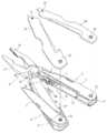
도 1은 본 발명에 따른 플라이어 수납기능을 갖는 다기능 공구를 나타낸 일부 분해 사시도.
도 2는 본 발명에 따른 플라이어 수납기능을 갖는 다기능 공구 중 주요부분을 나타낸 분해 사시도.
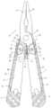
도 3은 본 발명에 따른 플라이어 수납기능을 갖는 다기능 공구의 플라이어가 인출된 상태를 나타낸 단면도.
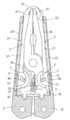
도 4는 본 발명에 따른 플라이어 수납기능을 갖는 다기능 공구의 플라이어가 수납(수용)된 상태를 나타낸 단면도.
도 5는 본 발명에 따른 플라이어 수납기능을 갖는 다기능 공구의 잠금 또는 해지 수단이 작동하여 플라이어가 인출된 상태를 유지시키는 동작을 설명하기 위한 요부 확대 사시도.
도 6은 본 발명에 따른 플라이어 수납기능을 갖는 다기능 공구의 잠금 또는 해지 수단이 작동하여 플라이어를 수납(수용)하기 위한 상태의 동작을 설명하기 위한 요부 확대 사시도이다.1 is a partially exploded perspective view showing a multifunctional tool having a pliers receiving function according to the present invention.
Figure 2 is an exploded perspective view showing the main part of the multifunctional tool having a plier receiving function according to the present invention.
Figure 3 is a cross-sectional view showing a state in which the pliers of the multi-function tool with a pliers receiving function according to the present invention withdrawn.
Figure 4 is a cross-sectional view showing a state in which the pliers of the multifunctional tool having a pliers receiving function according to the present invention (received).
Figure 5 is an enlarged perspective view of the main portion for explaining the operation of maintaining the pliers pulled out by operating the locking or unlocking means of the multifunction tool having a pliers storage function according to the present invention.
Figure 6 is an enlarged perspective view of the main portion for explaining the operation of the state for accommodating (accommodating) the pliers by operating the locking or unlocking means of the multifunction tool having a pliers storage function according to the present invention.
이하, 첨부된 도면을 참조하여 본 발명의 바람직한 실시 예의 구성 및 작동에 대하여 상세히 설명한다.Hereinafter, the configuration and operation of a preferred embodiment of the present invention will be described in detail with reference to the accompanying drawings.
도 1은 본 발명의 따른 플라이어 수납기능을 갖는 다기능 공구의 전체 또는 주요부분을 나타낸 분해 사시도로서, 부호 1은 잠금 또는 해지 수단, 2, 2'는 손잡이부, 3은 공구들, 4는 플라이어, 5는 작동부재, 6은 스톱퍼, 7, 7'는 가이드편, 8, 8'는 작동편을 나타낸다.1 is an exploded perspective view showing the whole or main parts of the multifunctional tool having a pliers receiving function according to the present invention, 1 is a locking or unlocking means, 2, 2 'handle portion, 3 tools, 4 a pliers, 5 is an operating member, 6 is a stopper, 7, 7 'is a guide piece, 8, 8' is an operating piece.
본 발명에 따른 플라이어 수납기능을 갖는 다기능 공구는, 도 1에서와 같이 기본 구성으로서, 두 개의 손잡이부(2, 2')와, 다수의 공구들(3)과, 커버(30)와, 플라이어(4)와, 이 플라이어(4)를 수납하기 위한 잠금 또는 해지 수단(1)을 구비하게 된다.Multifunctional tool having a pliers storage function according to the present invention, as shown in Figure 1, two handles (2, 2 '), a plurality of tools (3), the
상기 두 개의 손잡이부(2, 2')는 금속판을 펀칭하여 절단하고 절곡하여 단면이 "ㄷ" 형상을 이루도록 하여 수용공간(21, 21')을 마련하면서 일측이 고정핀(22)을 중심으로 회전할 수 있도록 상호 결합하여 출입구(23)가 되도록 이루어진다.The two
그리고 손잡이부(2, 2')의 상하면에는 칼, 미니톱, 나사 드라이버 등 일상 생활에 간편하게 사용될 다수의 공구들(3)을 결합하게 된다.In addition, the upper and lower surfaces of the
또한, 커버(30)는 외부로 노출되므로 장식 효과를 지니면서 일측은 고정볼트(31)에 의해 손잡이부(2, 2')에 고정되고, 다수의 공구들(3)이 손잡이부(2, 2')에 회전하면서 수납 되도록 타측은 힌지볼트(32) 및 힌지너트(33)에 의해 손잡이부(2, 2')에 결합되도록 이루어진다.In addition, since the
그리고 플라이어(4)는 통상적인 구성으로서 상기 손잡이부(2, 2')의 출입구(23)로 수납되면서 죠오(jaw, 41)와 아암(arm, 42) 그리고 죠오(jaw, 41')와 아암(arm, 42')이 각각 일체로 형성되고 힌지축(43)으로 결합되어 회동하도록 이루어진다. 이때 상기 플라이어(4)가 손잡이부(2, 2')의 수용공간(21, 21' )으로 수용되어 그 길이가 최소화됨으로써 휴대가 용이하도록 아암(42, 42')의 길이는 최소로 짧게 구성하게 된다. 또한, 상기 플라이어(4)는 힌지축(43)에 끼워져 내장된 비틀림코일스프링(47)의 탄성력에 의해 죠우(41)와 죠우(41') 사이가 벌어진 사용을 위한 준비 상태를 유지하도록 이루어졌다.And the
본 발명은 상기 플라이어(4)가 손잡이부(2, 2')의 수용공간(21, 21')으로 출몰하되 플라이어(4)를 안전한 상태에서 사용 및 보관할 수 있도록 잠금 또는 해지 수단(1)을 제공하게 된다.According to the present invention, the
본 발명의 핵심기술인 플라이어(4)의 잠금 또는 해지 수단(1)을 도 2 및 도 5를 통하여 상세하게 살펴보면, 플라이어(4)의 잠금 또는 해지를 위한 작동부재(5)와, 스톱퍼(6)와, 고정구멍틀(44)과, 가이드편(7, 7')과, 작동편(8, 8') 및 손잡이부(2)에 천공된 멈춤구멍(25)에 의하여 달성된다.Looking at the locking or unlocking means (1) of the pliers (4), which is the core technology of the present invention in detail with reference to Figures 2 and 5, the operating member (5) and the stopper (6) for locking or releasing the pliers (4) And a
작동부재(5)는 상기 플라이어(4)의 아암(42) 내측 수직면에 고정볼트(51)로 고정되고 비틀림코일스프링(52)에 의해 작동되며 전방에는 고정돌기(53)가 후방에는 걸림돌기(54)가 중앙의 상측으로는 레버(55)가 돌출되도록 "⊥" 형상으로 일체로 형성된다. 그리고 상기 비틀림코일스프링(52)은 레버(55)의 작동이 없는 평상시에는 항상 고정볼트(51)를 중심으로 고정돌기(53)를 하강(시계 반대방향으로 가압함)시키고 반대측의 걸림돌기(54)를 상승시키는 역할을 하게 된다.The
스톱퍼(6)는 상기 플라이어(4)의 아암(42)에 장착된 작동부재(5)의 일측 수직면에 삽입되고 통상적인 링형성의 나사에 의해 고정되면서 압축스프링(61)에 의해 출몰 작동되도록 계단형 봉 형태로 이루어진다. 그리고 스톱퍼(6)는 상기 작동부재(5)의 걸림돌기(54)의 회전을 정지(방지)시키는 안전장치의 역할을 수행하게 된다.The
고정구멍틀(44)은 상기 플라이어(4)의 아암(42')의 내측 수직면 하단에 돌출 형성된다. 즉, 고정구멍틀(44)은 인위적 힘에 의해 이동하여 일측면이 상기 스톱퍼(6)를 밀어 넣어 상기 작동부재(5)의 걸림돌기(54)의 고정상태를 해지시키는 역할과, 상기 스톱퍼(6)를 밀어 넣은 상태에서 상기 작동부재(5)의 레버(55)의 작동이 이루어져 작동부재(5)의 걸림돌기(54)가 시계방향으로 회전시켜 끼워 걸리도록 하여 휴대시 플라이어(4)의 아암(42)과 아암(42')의 벌어짐을 방지하는 역할을 하도록 이루어진다.The
가이드편(7, 7')은 상기 플라이어(4)의 이동을 안내하는 역할을 하는 것으로, 상기 "ㄷ" 형상으로 절곡된 손잡이부(2) 및 손잡이부(2')의 수직면에 플라이어(4)가 이동하는 길이방향으로 천공된 장공의 안내구멍(24) 및 안내구멍(24') 외측으로 접하면서 중앙부분이 끼워져 상기 안내구멍(24) 및 안내구멍(24')을 따라 이동하도록 이루어진다.Guide pieces (7, 7 ') serves to guide the movement of the pliers (4), the pliers (4) on the vertical surface of the
작동편(8, 8')은 수직면이 상기 가이드편(7, 7')에 체결볼트(71)에 의해 나사결합되도록 "ㄷ" 형으로 절곡 형성되고, 상기 플라이어(4)의 아암(42) 및 아암(42')의 상하부에 형성되는 단차부(45) 및 단차부(45')로 끼워지면서 힌지핀(46) 및 힌지핀(46')에 의해 결합되는 장공(81) 및 장공(81')을 각각 천공하여 이루어진다. The
그리고 상기 작동편(8, 8')의 선단과 아암(42) 및 아암(42')의 상하부에 형성된 단차부(45) 및 단차부(45')의 접촉부분은 호형으로 형성하여 힌지핀(46) 및 힌지핀(46')이 상기 작동편(8, 8')의 장공(81) 및 장공(81')의 공간으로 자유롭게 이동할 때 걸림이 없도록 구성된다.And the contact portion of the stepped
또한, 상기 손잡이부(2)에 멈춤구멍(25)을 천공하여 플라이어(4)가 손잡이부(2) 및 손잡이부(2')의 출입구(23)로부터 인출될 때 작동부재(5)의 고정돌기(53)가 끼워져 고정되도록 이루어진다. 즉, 상기 작동부재(5)의 고정돌기(53)는 비틀림코일스프링(52)의 탄성력에 의해 상기 손잡이부(2)의 멈춤구멍(25)에 끼워지게 되고, 이는 곧 플라이어(4)를 안전하게 사용할 수 있는 고정 상태를 유지하도록 이루어진다.Further, the
또한, 본 발명은 도 2 및 도 3에서와 같이 고정볼트(31) 및 힌지너트(33)에 의해 손잡이부(2) 및 손잡이부(2')에 결합되면서 상기 가이드편(7, 7')의 이동시 파지하는 손에 걸리는 것을 방지하고 파지가 편리하도록 내측면에 안내홈(91, 91')을 형성한 측면커버(9, 9')를 마련하게 된다.In addition, the present invention is coupled to the
다음으로, 이상과 같이 구성되는 본 발명에 따른 플라이어 수납기능을 갖는 다기능 공구의 작동에 대하여 설명한다.Next, the operation of the multifunctional tool having the pliers storage function according to the present invention configured as described above will be described.
먼저, 플라이어(4)를 사용할 수 있도록 인출한 상태는 도 3 및 도 5에서와 같이 잠금 또는 해지 수단(1) 중 하나인 작동부재(5)의 고정돌기(53)가 비틀림코일스프링(52)의 탄성력에 의해 상기 손잡이부(2)의 멈춤구멍(25)에 끼워진 상태이고, 이는 곧 플라이어(4)가 이동하지 못하도록 고정시킨 상태이므로 안전하게 플라이어(4)를 사용할 수 있게 된다.First, the pulled out so that the
상기 상태에서 손잡이부(2, 2')를 손으로 파지한 후 작동시키면 손잡이부(2, 2')가 플라이어(4)의 아암(42, 42')을 작동시킴과 동시에 이 아암(42, 42')은 힌지축(43)을 중심으로 회동하는 죠오(41, 41')를 작동시켜 피가공물을 집거나 절단하는 작업을 수행하게 된다.In the above state, when the
다음으로, 인출되어 있는 플라이어(4)를 손잡이부(2, 2')의 수용공간(21, 21')으로 밀어넣어 수납시키기 위해서는 먼저 도 6에서와 같이 손잡이부(2, 2')를 손으로 움켜잡으면 아암(42')에 형성된 고정구멍틀(44)의 측면이 아암(42)에 장착된 스톱퍼(6)를 압착하게 되며, 이때 상기 스톱퍼(6)는 밀려 들어가면서 압축스프링(61)을 압착하게 된다.Next, in order to push the pulled-out
다음으로, 작동부재(5)의 레버(55)를 도 5의 상태에서 도 6의 상태로 우측(시계방향)으로 고정볼트(51)를 중심으로 회전시키면 고정돌기(53)는 손잡이부(2)의 멈춤구멍(25)으로부터 빠져나오고 반대편의 걸림돌기(54)는 스톱퍼(6)를 압착하고 있는 고정구멍틀(44)로 유입되어 아암(42)과 아암(42')의 벌어짐을 방지하게 된다.Next, when the
상기 상태에서 작동부재(5)의 레버(55)를 더 끌어당기면 도 4에서와 같이 플라이어(4) 전체가 손잡이부(2, 2')의 수용공간(21, 21')으로 유입되어 수납된다.When the
상기 플라이어(4)가 손잡이부(2, 2')의 수용공간(21, 21')으로 유입되는 과정에서 플라이어(4)의 아암(42, 42')에 힌지핀(46, 46')으로 결합된 작동편(8, 8')과, 이 작동편(8, 8')을 고정하고 있는 가이드편(7, 7')이 손잡이부(2, 2')의 안내구멍(24, 24')을 따라 이동하게 된다.As the
상기와 같이 상기 플라이어(4)가 손잡이부(2, 2')의 수용공간(21, 21')으로 유입된 도 4와 같은 상태에서 끌어당기고 있던 작동부재(5)의 레버(55)를 놓으면 작동부재(5)의 비틀림코일스프링(52)의 반발력에 의해 작동부재(5)의 고정돌기(53)를 좌측(시계반대방향)으로 회동시키려할 때 작동부재(5)의 고정돌기(53)는 손잡이부(2)에 접촉되어 정지되 상태이고, 반대편의 걸림돌기(54)는 고정구멍틀(44)에 끼워진 상태이므로 아암(42) 및 아암(42') 그리고 손잡이부(2) 및 손잡이부(2')의 벌어짐을 방지하여 휴대가 편리하게 된다.As described above, when the
한편, 손잡이부(2, 2')의 수용공간(21, 21')에 수납되어 있던 플라이어(4)를 인출하여 사용하고자 할 때에는 작동부재(5)의 레버(55)를 밀어 플라이어(4) 전체를 밀어내어 작동부재(5)의 고정돌기(53)의 위치가 손잡이부(2)의 멈춤구멍(25)에 도달되면 비틀림코일스프링(52)의 반발력에 의해 고정볼트(51)을 중심으로 고정돌기(53)가 회전하여 멈춤구멍(25)에 도 5에서와 같이 끼워져 고정상태를 유지하게 된다.On the other hand, when the
상기 작동부재(5)의 고정돌기(53)가 멈춤구멍(25)에 끼워지면 반대편의 걸림돌기(54)는 고정구멍틀(44)로부터 이격되므로 아암(42) 및 아암(42') 그리고 손잡이부(2) 및 손잡이부(2')의 벌어짐이 가능한 상태가 되고, 이때 스톱퍼(6) 역시 압축스프링(61)의 복원력에 의해 원상태로 돌출되어 상기 걸림돌기(54)의 저면에 위치하여 작동부재(5)의 작동을 정지시켜 안정적인 고정상태를 유지하게 되며, 플라이어(4)의 힌지축(43)에 결합된 비틀림스프링(47)의 반발력으로 죠오(41, 14')가 벌어지는 상태가 되고, 상기 상태에서 플라이어(4)을 편리하게 사용할 수 있는 것이다.When the fixing
상시 플라이어(4)가 손잡이부(2, 2')의 수용공간(21, 21')으로 수납될 때 플라이어(4)의 아암(42, 42')에 힌지핀(46, 46')에 의해 장공(81, 81')이 결합된 작동편(8, 8')은 체결나사(71)로 결합된 가이드편(7, 7')이 손잡이부(2, 2')의 안내구멍(24, 24')을 따라 이동할 때 함께 이동하게 된다. 즉, 가이드편(7, 7')에 고정된 작동편(8, 8')의 장공(81, 81')에 끼워진 힌지핀(46, 46')에 의해 플라이어(4)의 아암(42, 42')에 상호 연결되어 있으므로 플라이어(4) 전체의 슬라이딩 운동과 손잡이부(2, 2')가 벌어지거나 오므라지는 작동을 할 때 함께 작동하게 되는 것이다.By the hinge pins 46 and 46 'to the
그리고 상기 가이드편(7, 7')이 손잡이부(2, 2')의 안내구멍(24, 24')을 따라 이동할 때 파지하는 손에 걸리는 것을 방지하기 위하여 상기 가이드편(7, 7')의 이동공간을 제공하는 안내홈(91, 91')을 갖는 측면커버(9, 9')를 손잡이부(2, 2')에 결합하여 사용하게 된다.And the
따라서, 본 발명의 상기 잠금 또는 해지 수단(1)은 플라이어(4)의 아암(42)에 장착되는 작동부재(5) 및 스톱퍼(6)와, 플라이어(4)의 아암(42')에 형성된 고정구멍틀(44)과, 상기 작동부재(5)의 고정돌기(53)가 끼워져 걸리도록 손잡이부(2)에 천공된 멈춤구멍(25)으로 이루어져 플라이어(4)를 고정상태에서 안정적으로 사용할 수 있도록 하고 편리하게 고정상태를 해지하면서 플라이어(4)를 손잡이부(2, 2')의 수용공간(21, 21')으로 수용시킨 후에는 벌어짐을 방지하게 되므로 항상 안전하게 휴대할 수 있는 유용한 것이다.Accordingly, the locking or releasing
그리고 손잡이부(2, 2')의 상하부분에 결합된 공구들(3)은 힌지볼트(32) 및 힌지너트(33)을 중심으로 회전시켜 꺼내어 사용할 수 있는 것이다.And the tools (3) coupled to the upper and lower portions of the handle portion (2, 2 ') is to be rotated around the
이상에서 본 발명의 바람직한 실시 예와 관련하여 설명하고 도시하였지만, 상기 도시되고 설명된 그대로의 구성 및 작용에 한정하는 것은 아니다. 따라서 상기 실시 예를 적절히 변형 및 수정 가능함을 당업자들은 잘 이해할 수 있으므로 적절한 변경 및 수정과 균등물들은 본 발명의 범위에 속하는 것으로 간주하여야 할 것이다.
While the present invention has been particularly shown and described with reference to exemplary embodiments thereof, it is to be understood that the invention is not limited to the disclosed exemplary embodiments. Accordingly, those skilled in the art will appreciate that various modifications, additions and substitutions are possible, without departing from the scope and spirit of the invention as disclosed in the accompanying claims.
1: 잠금 또는 해지 수단 2, 2': 손잡이부
21, 21': 수용공간 22, 고정핀
23: 출입구 24, 24': 안내구멍
25: 멈춤구멍 3: 공구들
31: 고정볼트 32: 힌지볼트
33: 힌지너트 4: 플라이어
41, 41': 죠오 42, 42': 아암
43: 힌지축 44: 고정구멍틀
45, 45':단차부 46, 46': 힌지핀
47: 비틀림코일스프링 5: 작동부재
51: 고정볼트 52: 비틀림코일스프링
53: 고정돌기 54: 걸림돌기
55: 레버 6: 스톱퍼
61: 압축스프링 7, 7': 가이드편
71: 체결나사 8, 8': 작동편
81, 81':장공 9, 9': 측면커버
91, 91' : 안내홈1: locking or releasing
21, 21 ': receiving
23:
25: hole 3: tools
31: Fixing bolt 32: Hinge bolt
33: hinge nut 4: pliers
41, 41 ':
43: hinge shaft 44: fixed hole frame
45, 45 ': stepped 46, 46': hinge pin
47: torsional coil spring 5: operating member
51: fixing bolt 52: torsion coil spring
53: fixing protrusion 54: locking protrusion
55: lever 6: stopper
61:
71: Tightening
81, 81 ':
91, 91 ': Home
Claims (2)
Translated fromKorean상기 플라이어(4)의 잠금 또는 해지 수단(1)은,
상기 플라이어(4)의 아암(42) 내측에 고정볼트(51)로 고정되고 비틀림코일스프링(52)에 의해 작동되며 전방에는 고정돌기(53)가 후방에는 걸림돌기(54)가 중앙의 상측으로는 레버(55)가 일체로 형성된 작동부재(5)와;
상기 플라이어(4)의 아암(42) 내측 수직면에 삽입 고정되고 압축스프링(61)에 의해 출몰 작동되면서 상기 작동부재(5)의 걸림돌기(54)의 회전을 정지시키는 스톱퍼(6)와;
상기 플라이어(4)의 아암(42')의 내측 수직면 하단에 돌출 형성되고 일측면으로 상기 스톱퍼(6)를 밀어 넣을 수 있도록 돌출되면서 회전되는 상기 작동부재(5)의 걸림돌기(54)가 끼워져 걸리는 고정구멍틀(44)과;
상기 "ㄷ" 형상으로 절곡된 손잡이부(2) 및 손잡이부(2')의 수직면에 길이방향으로 형성된 안내구멍(24) 및 안내구멍(24') 외측으로 접하면서 중앙부분이 끼워져 상기 안내구멍(24) 및 안내구멍(24')을 따라 이동하는 가이드편(7, 7')과;
상기 플라이어(4)의 아암(42) 및 아암(42')의 상하부에 형성되는 단차부(45) 및 단차부(45')로 끼워지면서 힌지핀(46) 및 힌지핀(46')에 의해 결합되는 장공(81) 및 장공(81')을 각각 천공하고 수직면이 상기 가이드편(7, 7')에 체결볼트(71)에 의해 나사결합되도록 "ㄷ"형으로 절곡형성된 작동편(8, 8'); 및
상기 플라이어(4)가 손잡이부(2) 및 손잡이부(2')의 출입구(23)로부터 인출된 상태를 유지할 수 있도록 작동부재(5)의 고정돌기(53)가 끼워져 고정되도록 손잡이부(2)에 멈춤구멍(25)을 천공하여 이루어진 것을 특징으로 하는 플라이어 수납기능을 갖는 다기능 공구.
Two handle portions 2 and 2 'provided with accommodation spaces 21 and 21' and one side is rotated about the fixing pin 22 to be the doorway 23, and the handle portions 2 and 2 '. A plurality of tools (3) disposed on the upper and lower surfaces of the) and the fixing bolt 31, the hinge bolt 32 and the hinge nut to accommodate the plurality of tools (3) in the handle portion (2, 2 ') A jaw (41), an arm (42) and a jaw (41) are accommodated in the cover 30 coupled to the 33 and the doorway 23 of the handles 2 and 2 '. And an arm 42 'are integrally formed with each other and are coupled to the hinge shaft 43 so that the pliers 4 are rotated, and locking or releasing means 1 for use and storage of the pliers 4 are provided. In the multifunctional portable tool
The locking or unlocking means 1 of the pliers 4,
It is fixed by the fixing bolt 51 inside the arm 42 of the pliers 4 and is operated by the torsion coil spring 52, the fixing projection 53 in the front and the locking projection 54 in the rear to the upper side of the center. An actuating member 5 in which the lever 55 is integrally formed;
A stopper 6 inserted into and fixed to an inner vertical surface of the arm 42 of the pliers 4 to stop the rotation of the engaging protrusion 54 of the operating member 5 while being pushed out by the compression spring 61;
The locking protrusion 54 of the operating member 5 is formed to protrude to the lower end of the inner vertical surface of the arm 42 'of the pliers 4 and to rotate while being protruded to push the stopper 6 to one side. A fixing hole frame 44 to be caught;
The guide portion 24 and the guide hole 24 'formed in the longitudinal direction on the vertical surface of the handle portion 2 and the handle portion 2' bent in the "C" shape is inserted into the center portion is inserted into the guide hole (24) and guide pieces (7, 7 ') moving along the guide hole (24');
The hinge pin 46 and the hinge pin 46 'are fitted into the stepped portion 45 and the stepped portion 45' formed on the upper and lower portions of the arm 42 and the arm 42 'of the pliers 4'. The operating piece 8 which is formed to be bent in a " c " shape so as to perforate the combined long hole 81 and the long hole 81 'and the vertical surface is screwed by the fastening bolts 71 to the guide pieces 7 and 7'. 8'); And
The handle portion 2 so that the fixing projection 53 of the operating member 5 is inserted and fixed so that the pliers 4 can be kept withdrawn from the door 23 of the handle portion 2 and the handle portion 2 '. Multi-function tool having a pliers storage function, characterized in that perforated stop hole 25 in the).
Priority Applications (1)
| Application Number | Priority Date | Filing Date | Title |
|---|---|---|---|
| KR1020120111887AKR101354497B1 (en) | 2012-10-09 | 2012-10-09 | A multi-function tool with pliers storage function |
Applications Claiming Priority (1)
| Application Number | Priority Date | Filing Date | Title |
|---|---|---|---|
| KR1020120111887AKR101354497B1 (en) | 2012-10-09 | 2012-10-09 | A multi-function tool with pliers storage function |
Publications (1)
| Publication Number | Publication Date |
|---|---|
| KR101354497B1true KR101354497B1 (en) | 2014-02-04 |
Family
ID=50269413
Family Applications (1)
| Application Number | Title | Priority Date | Filing Date |
|---|---|---|---|
| KR1020120111887AActiveKR101354497B1 (en) | 2012-10-09 | 2012-10-09 | A multi-function tool with pliers storage function |
Country Status (1)
| Country | Link |
|---|---|
| KR (1) | KR101354497B1 (en) |
Cited By (2)
| Publication number | Priority date | Publication date | Assignee | Title |
|---|---|---|---|---|
| KR101656189B1 (en)* | 2015-06-19 | 2016-09-22 | 코레일테크 주식회사 | Apparatus for keeping nut tighten for turn-out branching-off point and crossing |
| WO2023201025A1 (en)* | 2022-04-15 | 2023-10-19 | Milwaukee Electric Tool Corporation | Multipurpose hand tool |
Citations (4)
| Publication number | Priority date | Publication date | Assignee | Title |
|---|---|---|---|---|
| US6185771B1 (en) | 1999-12-06 | 2001-02-13 | John E. Trusty, Sr. | Pocket tool having slidably extensible pliers |
| US20010018778A1 (en) | 2000-03-03 | 2001-09-06 | Montague Phillip A. | Pocket tool with removable jaws |
| US6721984B1 (en) | 1998-09-04 | 2004-04-20 | Fiskars Brands, Inc. | Multifunction tool with replaceable implements |
| US20100122420A1 (en) | 2008-11-20 | 2010-05-20 | Fiskars Brands, Inc. | Multi-function tool with locking pliers |
- 2012
- 2012-10-09KRKR1020120111887Apatent/KR101354497B1/enactiveActive
Patent Citations (4)
| Publication number | Priority date | Publication date | Assignee | Title |
|---|---|---|---|---|
| US6721984B1 (en) | 1998-09-04 | 2004-04-20 | Fiskars Brands, Inc. | Multifunction tool with replaceable implements |
| US6185771B1 (en) | 1999-12-06 | 2001-02-13 | John E. Trusty, Sr. | Pocket tool having slidably extensible pliers |
| US20010018778A1 (en) | 2000-03-03 | 2001-09-06 | Montague Phillip A. | Pocket tool with removable jaws |
| US20100122420A1 (en) | 2008-11-20 | 2010-05-20 | Fiskars Brands, Inc. | Multi-function tool with locking pliers |
Cited By (2)
| Publication number | Priority date | Publication date | Assignee | Title |
|---|---|---|---|---|
| KR101656189B1 (en)* | 2015-06-19 | 2016-09-22 | 코레일테크 주식회사 | Apparatus for keeping nut tighten for turn-out branching-off point and crossing |
| WO2023201025A1 (en)* | 2022-04-15 | 2023-10-19 | Milwaukee Electric Tool Corporation | Multipurpose hand tool |
Similar Documents
| Publication | Publication Date | Title |
|---|---|---|
| US11458609B2 (en) | Multipurpose tool | |
| US10464199B2 (en) | Multi-purpose tool having removable handle for use as a hand tool | |
| CA2617478C (en) | Multipurpose tool | |
| CA2474846C (en) | Multi-function tool with spring biased implement | |
| US6341423B1 (en) | Multiple purpose automobile tool | |
| JP5410927B2 (en) | Electric tool with hook for electric tool and electric tool hook | |
| US6886257B2 (en) | Automatically loadable and blade-stabilizing utility knife | |
| US11904450B2 (en) | Multi-function pliers | |
| US20080289190A1 (en) | Pocket Safety Cutter | |
| EP1733854A2 (en) | Improved folding knife | |
| EP2826594B1 (en) | Retractable pliers | |
| US8037787B2 (en) | Multi-function tool having retractable jaws | |
| DK2324962T3 (en) | Utensil with integrated carabiner | |
| CN218978185U (en) | Ratchet type key chain accessory and ratchet type locking piece | |
| JP3389529B2 (en) | Multifunctional pocket tool with pliers | |
| TW201603968A (en) | Stripping tool | |
| KR101354497B1 (en) | A multi-function tool with pliers storage function | |
| CA2412516A1 (en) | Multi-purpose hand-held unit | |
| CN202507297U (en) | Multipurpose folding knife | |
| US20120103146A1 (en) | High torque screwdriver | |
| KR200178648Y1 (en) | Tool for having variuos uses | |
| CN111819036A (en) | Retainer for holding the replaceable part of the tool | |
| AU4351799A (en) | Multi-purpose folding tool | |
| HK1123255B (en) | Folding tool |
Legal Events
| Date | Code | Title | Description |
|---|---|---|---|
| A201 | Request for examination | ||
| PA0109 | Patent application | Patent event code:PA01091R01D Comment text:Patent Application Patent event date:20121009 | |
| PA0201 | Request for examination | ||
| E701 | Decision to grant or registration of patent right | ||
| PE0701 | Decision of registration | Patent event code:PE07011S01D Comment text:Decision to Grant Registration Patent event date:20131021 | |
| GRNT | Written decision to grant | ||
| PR0701 | Registration of establishment | Comment text:Registration of Establishment Patent event date:20140116 Patent event code:PR07011E01D | |
| PR1002 | Payment of registration fee | Payment date:20140117 End annual number:3 Start annual number:1 | |
| PG1601 | Publication of registration | ||
| FPAY | Annual fee payment | Payment date:20161229 Year of fee payment:4 | |
| PR1001 | Payment of annual fee | Payment date:20161229 Start annual number:4 End annual number:4 | |
| FPAY | Annual fee payment | Payment date:20171110 Year of fee payment:5 | |
| PR1001 | Payment of annual fee | Payment date:20171110 Start annual number:5 End annual number:5 | |
| FPAY | Annual fee payment | Payment date:20190114 Year of fee payment:6 | |
| PR1001 | Payment of annual fee | Payment date:20190114 Start annual number:6 End annual number:6 | |
| PR1001 | Payment of annual fee | Payment date:20201105 Start annual number:8 End annual number:8 | |
| PR1001 | Payment of annual fee | Payment date:20211109 Start annual number:9 End annual number:9 | |
| PR1001 | Payment of annual fee | Payment date:20221018 Start annual number:10 End annual number:10 | |
| PR1001 | Payment of annual fee | Payment date:20241016 Start annual number:12 End annual number:12 |