KR101353482B1 - Stand and Electronic Equipment having it - Google Patents
Stand and Electronic Equipment having itDownload PDFInfo
- Publication number
- KR101353482B1 KR101353482B1KR1020120082513AKR20120082513AKR101353482B1KR 101353482 B1KR101353482 B1KR 101353482B1KR 1020120082513 AKR1020120082513 AKR 1020120082513AKR 20120082513 AKR20120082513 AKR 20120082513AKR 101353482 B1KR101353482 B1KR 101353482B1
- Authority
- KR
- South Korea
- Prior art keywords
- stand
- rail
- movable body
- fixed
- elastic member
- Prior art date
- Legal status (The legal status is an assumption and is not a legal conclusion. Google has not performed a legal analysis and makes no representation as to the accuracy of the status listed.)
- Active
Links
Images


Classifications
- H—ELECTRICITY
- H04—ELECTRIC COMMUNICATION TECHNIQUE
- H04N—PICTORIAL COMMUNICATION, e.g. TELEVISION
- H04N5/00—Details of television systems
- H04N5/64—Constructional details of receivers, e.g. cabinets or dust covers
- H04N5/655—Construction or mounting of chassis, e.g. for varying the elevation of the tube
- G—PHYSICS
- G06—COMPUTING OR CALCULATING; COUNTING
- G06F—ELECTRIC DIGITAL DATA PROCESSING
- G06F1/00—Details not covered by groups G06F3/00 - G06F13/00 and G06F21/00
- G06F1/16—Constructional details or arrangements
- G—PHYSICS
- G06—COMPUTING OR CALCULATING; COUNTING
- G06F—ELECTRIC DIGITAL DATA PROCESSING
- G06F1/00—Details not covered by groups G06F3/00 - G06F13/00 and G06F21/00
- G06F1/16—Constructional details or arrangements
- G06F1/1601—Constructional details related to the housing of computer displays, e.g. of CRT monitors, of flat displays
- G—PHYSICS
- G06—COMPUTING OR CALCULATING; COUNTING
- G06F—ELECTRIC DIGITAL DATA PROCESSING
- G06F1/00—Details not covered by groups G06F3/00 - G06F13/00 and G06F21/00
- G06F1/16—Constructional details or arrangements
- G06F1/1613—Constructional details or arrangements for portable computers
- G06F1/1626—Constructional details or arrangements for portable computers with a single-body enclosure integrating a flat display, e.g. Personal Digital Assistants [PDAs]
- G—PHYSICS
- G06—COMPUTING OR CALCULATING; COUNTING
- G06F—ELECTRIC DIGITAL DATA PROCESSING
- G06F1/00—Details not covered by groups G06F3/00 - G06F13/00 and G06F21/00
- G06F1/16—Constructional details or arrangements
- G06F1/1613—Constructional details or arrangements for portable computers
- G06F1/1633—Constructional details or arrangements of portable computers not specific to the type of enclosures covered by groups G06F1/1615 - G06F1/1626
- G06F1/1656—Details related to functional adaptations of the enclosure, e.g. to provide protection against EMI, shock, water, or to host detachable peripherals like a mouse or removable expansions units like PCMCIA cards, or to provide access to internal components for maintenance or to removable storage supports like CDs or DVDs, or to mechanically mount accessories
- G06F1/166—Details related to functional adaptations of the enclosure, e.g. to provide protection against EMI, shock, water, or to host detachable peripherals like a mouse or removable expansions units like PCMCIA cards, or to provide access to internal components for maintenance or to removable storage supports like CDs or DVDs, or to mechanically mount accessories related to integrated arrangements for adjusting the position of the main body with respect to the supporting surface, e.g. legs for adjusting the tilt angle
- H—ELECTRICITY
- H04—ELECTRIC COMMUNICATION TECHNIQUE
- H04N—PICTORIAL COMMUNICATION, e.g. TELEVISION
- H04N1/00—Scanning, transmission or reproduction of documents or the like, e.g. facsimile transmission; Details thereof
- H04N1/00519—Constructional details not otherwise provided for, e.g. housings, covers
- H04N1/00562—Supporting the apparatus as a whole, e.g. stands
Landscapes
- Engineering & Computer Science (AREA)
- Theoretical Computer Science (AREA)
- General Engineering & Computer Science (AREA)
- Computer Hardware Design (AREA)
- Human Computer Interaction (AREA)
- Physics & Mathematics (AREA)
- General Physics & Mathematics (AREA)
- Multimedia (AREA)
- Signal Processing (AREA)
- Devices For Indicating Variable Information By Combining Individual Elements (AREA)
- Casings For Electric Apparatus (AREA)
Abstract
Translated fromKoreanDescription
Translated fromKorean본 발명은 스탠드에 관한 것으로서, 더욱 상세하게는 좌우 회전 가능한 스탠드 및 이를 구비하는 전자기기에 관한 것이다.The present invention relates to a stand, and more particularly, to a left and right rotatable stand and an electronic device having the same.
모니터, PDP, LED TV, 3D TV 등의 전자기기들은 전자기기 본체를 거치프레임을 이용하여 벽에 고정하거나 스탠드를 이용하여 가구 등의 바닥면에 지지하여 사용한다. 특히, 최근 판매되고 있는 전자기기들은 본체가 점점 슬림화됨에 따라 일체로 마련되는 스탠드도 디자인적인 면을 고려해서 슬림해지고 있다.Electronic devices such as monitors, PDPs, LED TVs, and 3D TVs are used to fix the main body of the electronic device to a wall using a mounting frame or to support the floor of furniture such as a stand using a stand. In particular, recently sold electronic devices are slimmer in consideration of the design side of the stand is also provided as the body is gradually slimmer.
종래 전자기기들은 대형 본체에 맞게 스탠드도 대형이기 때문에 시야각을 조절할 수 있도록 스탠드 내부에 본체의 설치 방향을 변경할 수 있는 구조를 포함하고 있다. 하지만, 최근의 소형화 경향에 맞춰 제작되는 슬림한 스탠드에는 본체의 설치 방향을 변경할 수 있는 구조를 마련하기가 용이하지 않기 때문에, 본체의 설치 방향을 변경하고자 할 경우는 스탠드 자체를 설치면으로부터 회전 이동시켜야 한다.Conventional electronic devices have a structure that can change the installation direction of the main body in the stand to adjust the viewing angle because the stand is also large to fit the large main body. However, it is not easy to provide a structure that can change the installation direction of the main body in a slim stand manufactured in accordance with the recent miniaturization trend, so if the user wants to change the installation direction of the main body, the stand itself is rotated from the installation surface. You have to.
본 발명의 실시 예는 슬림하면서 좌우 회전이 가능한 스탠드 및 이를 구비하는 전자기기를 제공하고 자 한다.An embodiment of the present invention is to provide a slim and left-right rotation stand and an electronic device having the same.
본 발명의 일 측면에 따르면, 전자기기를 설치면에 지지하는 스탠드에 있어서, 스탠드의 바닥면에 마련되는 베이스와, 베이스에 마련되는 레일과, 레일에 고정 마련되는 고정체와, 레일 내부에 이동 가능하게 설치되며 설치면과 접촉하는 가동체와, 가동체와 고정체 사이에 마련되어 가동체가 일정한 힘으로 좌우 이동할 수 있도록 하는 탄성부재를 포함하는 스탠드가 제공될 수 있다.According to an aspect of the present invention, in the stand for supporting the electronic device on the installation surface, the base provided on the bottom surface of the stand, the rail provided on the base, the fixed body fixed to the rail, and move inside the rail It is possible to provide a stand including a movable body which is installed to be in contact with the installation surface and an elastic member provided between the movable body and the fixed body to allow the movable body to move left and right with a constant force.
또한, 상기 탄성부재는 정하중 스프링(constant force spring)이며, 상호 반대방향으로 작용하도록 좌우 한 쌍으로 마련될 수 있다.In addition, the elastic member is a constant force spring (constant force spring), may be provided in a pair of left and right to act in opposite directions.
또한, 상기 고정체는 원호 형상의 레일 중앙에 마련되며, 상기 가동체는 레일의 중앙에서 좌우로 이동할 수 있다.In addition, the fixed body is provided in the center of the rail of the arc shape, the movable body can move from side to side in the center of the rail.
또한, 상기 탄성부재는 권취단과 고정단을 포함하고, 상기 가동체는 내부에 중공과 개구공을 구비하여, 상기 중공에는 권취단이 설치되고 상기 개구공에는 고정단이 설치되며, 상기 고정단은 상기 고정체에 마련되는 걸림홈에 걸린다.In addition, the elastic member includes a winding end and a fixed end, the movable body is provided with a hollow and an opening hole therein, the winding end is installed in the hollow and the fixed end is installed in the opening hole, the fixed end is It is caught in the locking groove provided in the fixed body.
또한, 상기 탄성부재는 권취단과 고정단을 포함하고, 상기 레일은 중공과 개구공을 포함하는 고정체를 구비하여, 상기 중공에는 권취단이 설치되고 상기 개구공에는 고정단이 설치되며, 상기 고정단은 상기 가동체에 마련되는 걸림홈에 걸린다.In addition, the elastic member includes a winding end and a fixed end, the rail is provided with a fixed body including a hollow and an opening hole, the winding end is installed in the hollow and the fixed end is installed in the opening hole, the fixed The stage is caught by a locking groove provided in the movable body.
또한, 상기 가동체는 설치면 측에 커버를 구비하고, 상기 커버는 가동체와 마주보는 면에 회동결합면을 구비하여 설치면이 경사진 경우 가동체가 회동결합면을 중심으로 틸팅되도록 하여 커버가 설치면에 밀착되도록 할 수 있다.In addition, the movable body is provided with a cover on the installation surface side, the cover is provided with a rotating coupling surface on the surface facing the movable body so that the movable body is tilted around the rotating coupling surface when the installation surface is inclined. It can be in close contact with the installation surface.
또한, 상기 스탠드의 바닥면에는 복수의 롤러유닛이 더 마련될 수 있다.In addition, a plurality of roller units may be further provided on the bottom surface of the stand.
또한, 상기 레일과 롤러유닛은 동일한 원주 상에 배치될 수 있다.In addition, the rail and the roller unit may be disposed on the same circumference.
본 발명의 다른 측면에 따르면, 상기와 같이 마련되는 스탠드를 구비하는 전자기기를 제공할 수 있다.According to another aspect of the invention, it is possible to provide an electronic device having a stand provided as described above.
본 발명의 실시 예에 따른 스탠드 및 이를 구비하는 전자기기는 설치면과 접하는 스탠드의 바닥면에 회전제어유닛 및 롤러유닛을 설치함으로써 스탠드가 설치면에 접촉된 상태에서도 좌우로 회전하여 시야각을 조절할 수 있다.The stand according to the embodiment of the present invention and an electronic device having the same may adjust the viewing angle by rotating the left and right sides even when the stand is in contact with the installation surface by installing the rotation control unit and the roller unit on the bottom surface of the stand in contact with the installation surface. have.
또한, 본 발명의 실시 예에 따른 스탠드 및 이를 구비하는 전자기기는 회전제어유닛의 내부에 한 쌍의 정하중 스프링을 설치함으로써 좌우 회전 시 일정한 힘으로 전자기기를 좌우 회전 이동할 수 있다.In addition, the stand and the electronic device having the same according to an embodiment of the present invention can be installed to rotate the electronic device left and right by a constant force when rotating the left and right by installing a pair of static load spring inside the rotation control unit.
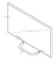
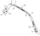
도 1 및 도 2는 본 발명의 일 실시 예에 따른 스탠드를 구비하는 전자기기를 도시한 사시도이다.
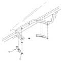
도 3는 본 발명의 일 실시 예에 따른 스탠드에 마련되는 회전제어유닛과 롤러유닛을 도시한 도면이다.
도 4는 본 발명의 일 실시 예에 따른 회전제어유닛을 분해 도시한 도면이다.
도 5 및 도 6은 본 발명의 일 실시 예에 따른 스탠드의 회전제어유닛의 동작을 설명하기 위한 도면이다.
도 7은 본 발명의 다른 실시 예에 따른 스탠드의 회전제어유닛을 도시한 분해 사시도이다.
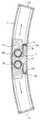
도 8은 본 발명의 다른 실시 예에 따른 스탠드의 회전제어유닛을 도시한 평단면도이다.
도 9는 본 발명의 다른 실시 예에 따른 스탠드의 회전제어유닛을 도시한 측단면도이다.
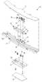
도 10은 본 발명의 다른 실시 예에 따른 스탠드에 마련되는 회전제어유닛과 롤러유닛을 구비하는 스탠드를 도시한 도면이다.
도 11은 본 발명의 다른 실시 예에 따른 스탠드의 회전제어유닛의 동작을 설명하기 위한 도면이다.1 and 2 are perspective views showing an electronic device having a stand according to an embodiment of the present invention.
3 is a view showing a rotation control unit and a roller unit provided in the stand according to an embodiment of the present invention.
4 is an exploded view illustrating a rotation control unit according to an embodiment of the present invention.
5 and 6 are views for explaining the operation of the rotation control unit of the stand according to an embodiment of the present invention.
7 is an exploded perspective view illustrating a rotation control unit of a stand according to another embodiment of the present invention.
8 is a cross-sectional view showing a rotation control unit of the stand according to another embodiment of the present invention.
9 is a side cross-sectional view showing a rotation control unit of the stand according to another embodiment of the present invention.
10 is a view showing a stand having a rotation control unit and a roller unit provided in the stand according to another embodiment of the present invention.
11 is a view for explaining the operation of the rotation control unit of the stand according to another embodiment of the present invention.
이하에서는 본 발명의 실시 예들을 첨부 도면을 참조하여 상세히 설명한다. 이하에 소개되는 실시 예들은 본 발명이 속하는 기술분야에서 통상의 지식을 가진 자에게 본 발명의 사상이 충분히 전달될 수 있도록 하기 위해 예로서 제공되는 것이다. 본 발명은 이하 설명되는 실시 예들에 한정되지 않고 다른 형태로 구체화될 수도 있다. 본 발명을 명확하게 설명하기 위하여 설명과 관계없는 부분은 도면에서 생략하였으며 도면들에 있어서, 구성요소의 폭, 길이, 두께 등은 편의를 위하여 과장되어 표현될 수 있다. 명세서 전체에 걸쳐서 동일한 참조번호들은 동일한 구성요소들을 나타낸다.Hereinafter, embodiments of the present invention will be described in detail with reference to the accompanying drawings. The embodiments described below are provided by way of example so that those skilled in the art will be able to fully understand the spirit of the present invention. The present invention is not limited to the embodiments described below, but may be embodied in other forms. In order to clearly explain the present invention, parts not related to the description are omitted from the drawings, and the width, length, thickness, etc. of the components may be exaggerated for convenience. Like numbers refer to like elements throughout.
도 1 내지 도 3은 본 발명의 일 실시 예에 따른 스탠드를 구비하는 전자기기의 일례로 모니터, TV 등의 디스플레이(1)를 도시한 것으로, 본 발명은 이에 한정되지 않고 스탠드를 이용하는 다른 전자기기에도 당업자가 적절하게 변형 및 수정하여 용이하게 설치할 수 있음은 물론이다. 또한, 스탠드는 전자기기 본체와 일체 또는 착탈 가능하게 설치될 수 있다.1 to 3 illustrate a
도면을 참조하면, 본 실시 예의 스탠드(2)는 전자기기 본체를 가구나 바닥 등의 설치면에 거치한 상태에서 약 20도 정도 좌우 회전할 수 있도록 한다. 이를 위해 스탠드(2)는 도 3에 도시한 바와 같이 그 바닥면에 복수의 회전제어유닛(10)과 롤러유닛(20)을 구비하며, 회전제어유닛(10)과 롤러유닛(20)은 스탠드(2)의 바닥면보다 약간 돌출 마련되어 설치면에 지지된다.Referring to the drawings, the
회전제어유닛(10)은 도 4에 도시한 바와 같이 스탠드에 매립 설치되는 베이스(11)와, 베이스(11)에 마련되는 레일(12)과, 레일(12)에 마련되는 고정체(13)와, 레일(12)에 대해 상대 이동 가능하게 설치되는 가동체(15)와, 고정체(13)와 가동체(15)를 연결하는 탄성부재(19)를 포함한다.As shown in FIG. 4, the
베이스(11)는 회전제어유닛(10)이 스탠드의 중심에 대해 대칭적으로 좌우 회전할 수 있도록 길이방향으로 원호 형상을 가지며, 양단은 판 형상의 베이스 몸체로부터 직각 밴딩하여 스토퍼(11a)를 형성함으로써 가동체(15)가 움직일 수 있는 구간을 제한한다.The
베이스에 결합되는 레일(12)은 베이스(11)와 동일하게 길이방향을 따라 원호 형상을 가진다. 레일은 단방향으로 일측(도면에서 하측)이 개방된 'ㄷ'자 형태의 레일부(12a)를 가지며, 원호의 내측면 중심에 센터홀(12b)을 갖는다. 레일(12)의 길이방향 양 끝단에 마련되는 개구는 베이스(11)의 스토퍼(11a)에 의해 폐쇄된다.The
고정체(13)는 레일(12)과 마찬가지로 원호 형상으로 마련되며, 레일(12)의 센터홀(12b)과 결합되는 센터돌기(13a)를 중심에 구비하여 레일(12) 내벽에 고정 설치된다. 고정체(13)의 양단에는 레일(12)의 내벽과 이격해서 걸림홈(13b)이 양측에 마련되어 후술할 한 쌍의 탄성부재(19) 중 하나의 고정단(19a)이 좌우 이동 시 선택적으로 걸린다.The
가동체(15)는 레일(12) 내부에 삽입되어 원호 형상의 레일부(12a)를 따라 이동 가능하도록 설치된다. 또한, 가동체(15)의 전후면에는 레일가이드(15a,15b)가 돌출 마련되어 좌우 이동 중 레일부(12a)로부터 이탈되지 않도록 결합되며, 이 레일가이드(15a,15b)에 의해 가동체(15)는 레일(12)을 안정적으로 슬라이딩 이동한다. 전방측 레일가이드(15a)는 좌우 이동 중 레일(12) 내부에 돌출되어 있는 고정체(13)에 걸리지 않도록 수평레일가이드(15c)를 구비한다. 수평레일가이드(15c)의 하측은 고정체(13)가 통과하며, 상측은 레일부(12a)의 내면이 슬라이딩 접촉한다.The
또한, 가동체(15)는 내부에 한 쌍의 중공(15d)을 가지며, 중공(15d)은 가동체(15)에 마련되는 개구공(15e)을 통해 외부와 연결된다. 개구공(15e)은 서로 대향해서 외측을 향해 개구되어 있으며, 개구공(15e)을 형성하기 위해 가동체(15)는 전방측 레일가이드(15a)가 마련된 가이드웰(16)이 본체로부터 이격 마련된다. 중공(15d)에는 탄성부재(19)의 일측 권취단(19b)이 설치되며, 탄성부재(19)의 타측 고정단(19a)은 개구공(15e)을 통해 가동체(15) 외부로 노출되어 고정체(13)의 걸림홈(13b)에 걸린다. 가동체(15)는 하부에 조립되는 가동체 커버(17)에 의해 내부가 폐쇄되며, 커버(17)에는 설치면과 접촉하는 러버 플레이트(18)가 설치된다. 가동체 커버(17)와 러버 플레이트(18)는 레일부(12a)보다 돌출되어 설치면에 접촉된다.In addition, the
탄성부재(19)는 일정한 곡율로 밴딩된 판 형상의 스프링으로 직선으로 잡아 늘릴 때 생기는 하중이 스트로크에 관계없이 일정한 정하중 스프링(constant force spring)이다. 정하중 스프링은 한 방향으로만 하중을 갖기 때문에, 본 실시 예에서는 고정체(13)를 중심으로 좌우 양방향으로 회전하는 스탠드의 특성상 탄성부재(19)를 좌우 한 쌍으로 마련하고 상호 반대방향으로 설치한다. 탄성부재(19)는 고정단(19a)과 권취단(19a)을 갖는다.The
도 3에 도시되어 있는 롤러유닛(20)은 하우징 내의 샤프트 상에 회전 가능하게 마련되는 롤러를 포함하는 통상의 롤러 구조로서, 다수개가 스탠드(2)에 회전제어유닛(10)과 동일한 원주 상에 배치되어 스탠드(2)의 회전을 보다 부드럽게 구현하고 설치면과의 평형 밸런스를 유지한다. 롤러유닛(20)은 스탠드의 사이즈에 따라 삭제될 수도 있다.The
그러면, 상기와 같은 구성을 갖는 스탠드 및 이를 구비하는 전자기기의 동작을 도 5 및 도 6을 참조하여 설명하기로 한다.Then, the operation of the stand having the above configuration and the electronic device having the same will be described with reference to FIGS. 5 and 6.
도 5는 전자기기 본체의 좌우 방향을 조절하기 전 초기 설정으로 스탠드(2)의 가동체(15)는 레일(12)의 중앙 즉, 고정체(13)의 후방에 위치하며, 한 쌍의 탄성부재(19)의 각 고정단(19a)은 고정체(13)의 양측 걸림홈(13b)에 각각 걸린 상태이다.5 is an initial setting before adjusting the left and right directions of the main body of the electronic device, the
상기 상태에서 사용자가 전자기기 본체의 시야각을 조절하기 위해 전자기기 본체를 좌우로 움직이면, 스탠드(2)의 바닥면에 매립 고정되어 있는 레일(12)은 도 6에 도시한 바와 같이 설치면에 고정되어 있는 가동체(15)에 대해 상대적으로 이동한다.In the above state, when the user moves the electronic device main body left and right to adjust the viewing angle of the electronic device main body, the
즉, 레일(12)이 이동하면 가동체(15)는 레일(12)에 고정 마련되어 있는 고정체(13)에 대해 거리가 멀어지며, 이때 멀어지는 거리만큼 걸림홈(13b)에 걸려 있는 일측 탄성부재(19)의 고정단(19a) 스트로크가 늘어나면서 일정한 하중이 전자기기 본체를 통해 사용자에게 전달된다. 따라서, 사용자가 전자기기를 좌우 0 ~ 20도 중 어느 각도로 틀더라도 항상 일정한 텐션(하중)을 느끼도록 할 수 있다. 이때, 스트로크가 연장되는 탄성부재의 반대편에 위치하는 다른 탄성부재(19)의 고정단(19a)은 고정체(13)의 걸림홈(13b)로부터 이격되므로 하중을 발생시키지 않는다.That is, when the
한편, 본 실시 예에 따라 스탠드(2)에 마련되는 회전제어유닛(10)은 스탠드에 조립하기 전 단품 상태에서는 탄성부재(19)의 복원력에 의해 가동체(15)가 이동 후 소정 시간이 지나면 최초 상태(가동체와 고정체가 일치)로 돌아가지만, 전자기기에 설치할 경우에는 전자기기 본체의 자중에 의해 탄성부재의 복원력에 대항하는 하중이 회전제어유닛에 충분히 가해지기 때문에 이동 상태를 유지할 수 있다. 또한, 탄성부재(19)는 권취단(19b)에 위치하는 판스프링의 단부가 중공 내부에 고정하지 않더라도 베이스(11)의 스토퍼(11a)에 의해 가동체(15)의 이동거리가 제한되기 때문에 안정적으로 탄성 동작할 수 있다.On the other hand, the
도 8 및 도 9는 본 발명의 다른 실시 예에 따른 스탠드 및 이를 구비하는 전자기기를 도시한 도면이다. 본 실시 예는 일 실시 예와 다른 점을 중심으로 설명하며, 동일한 참조부호는 동일한 기능을 수행하는 것이므로 상세한 설명을 생략한다.8 and 9 are views illustrating a stand and an electronic device having the same according to another embodiment of the present invention. The present embodiment will be described based on the difference from the embodiment, and the same reference numerals are to perform the same function, detailed description thereof will be omitted.
본 실시 예에 따른 스탠드에 마련되는 회전제어유닛(30)은 일 실시 예의 회전제어유닛(10)과 대비해 볼 때, 한 쌍의 탄성부재(19)가 가동체(35)가 아닌 고정체(33)에 마련되며, 고정체(33)는 레일(32)에 일체로 마련되는 점이 상이하다.As compared with the
도 8을 참조하여 좀 더 구체적으로 살펴 보면, 레일(32)은 중심에 탄성부재(19) 한 쌍의 각 권취단(19b)을 수용할 수 있도록 중공(33a)과 개구공(33b)을 구비하며, 개구공(33b)은 레일(32)에 마련되는 고정체(33)의 가이드웰(34)을 고정체 본체로부터 돌출시켜 마련한다.Looking more specifically with reference to Figure 8, the
또한, 가동체(35)는 탄성부재(19)의 고정단(19a)이 걸리도록 걸림홈(35a)을 양단에 구비한다. 걸림홈(35a)은 이동 방향에 따라 한 쌍의 탄성부재(19) 중 하나가 선택적으로 걸리도록 하여 탄성부재가 외력에 대해 일정한 하중을 받도록 한다.In addition, the
또한, 본 실시 예의 가동체(35)는 내부에 경사조절유닛을 갖는다. 경사조절유닛은 스탠드(2)가 거치되는 설치면이 경사진 경우에도 가동체(35)의 커버(37) 및 러버 플레이트(39)가 항상 설치면에 밀착되도록 하여 스탠드(2)가 밀리는 현상을 방지한다.In addition, the
도 9의 (a)(b)를 참조하여 좀 더 구체적으로 살펴보면, 가동체(35)의 하면에 결합하는 커버(37)는 가동체(35)와 마주보는 결합면에 고정결합면(37a)과 회동결합면(37b)을 구비한다. 고정결합면(37a)은 가동체(35)와 장방형의 홈돌기 형태로 결합되며, 돌기 내부에는 수직 방향으로 탄성력을 갖는 한 쌍의 스프링(38a)이 마련된다. 회동결합면(37b)은 고정결합면(37a)의 좌우 측에 마련되고 호 형상의 홈돌기 형태로 가동체(35)와 결합되며, 돌기 내부에는 수직 방향을 안내하는 가이드핀(38b)이 마련된다. 회동결합면(37b)과 가이드핀(38b)은 도 9의 (b)에 도시한 바와 같이 설치면이 경사진 경우 가동체(35)가 회동결합면(37b)을 중심으로 틸팅되도록 가이드하며, 스프링(38a)은 스탠드(2)가 설치면에 경사져 있더라도 가동체(35)와 레일(32)을 탄성 지지하여 스탠드의 좌우 이동 시 슬립이 발생하는 것을 방지한다. 이러한 경사조절유닛은 일 실시 예에도 적용 가능함은 물론이다.Looking at in more detail with reference to (a) (b) of Figure 9, the
한편, 본 실시 예에 따른 회전제어유닛(30)은 일 실시 예와 마찬가지로 한 쌍의 회전제어유닛(30A)이 스탠드의 좌우 측면에 마련되고 그 사이사이에 롤러유닛(20)이 다수 설치될 수 있으며, 더 나아가 도 10 및 도 11에 도시한 바와 같이 또 하나의 회전제어유닛(30B)이 스탠드의 중심에 마련되어 스탠드의 좌우 이동을 보다 용이하도록 한다. 스탠드의 중심에 마련되는 회전제어유닛(30)과 측면에 마련되는 회전제어유닛(30)은 이동하는 회전각이 다르기 때문에 회전제어유닛의 크기는 당업자가 적절히 수정 및 변경하여 마련할 수 있다.Meanwhile, in the
또한, 세 개의 회전제어유닛(30A,30B)이 정확히 연동될 수 있도록 각 회전제어유닛(30A,30B)들은 싱크케이블(40)로 연결된다. 싱크케이블(40)은 플럭시블한 소재의 POM 또는 Nylon이 사용될 수 있다. 싱크케이블(40)을 연결 고정할 수 있도록 각 회전제어유닛(30A,30B)은 가동체(35)의 양단에 케이블고정홀(36)을 각각 구비한다. 케이블고정홀(36)과 싱크케이블(40)은 후크 등의 방식으로 간편하게 연결할 수 있도록 하며, 연결 시에는 마주보는 회전제어유닛(30A,30B)의 각 가동체를 약 10도 정도씩 상호 근접 이동시켜 강제 결합한다.In addition, each rotation control unit (30A, 30B) is connected to the
상기와 같이 마련되는 회전제어유닛 및 롤러유닛을 포함하는 스탠드 및 이를 구비하는 전자기기의 동작은 상술한 일 실시 예와 동일하므로 설명은 생략한다.Since the operation of the stand including the rotation control unit and the roller unit and the electronic device having the same are provided as described above, the description thereof will be omitted.
1..전자기기 본체(디스플레이)2..스탠드
10..회전제어유닛12..레일
13..고정체15..가동체
19..탄성부재20..롤러유닛
30,30A,30B..회전제어유닛32..레일
33..고정체35..가동체
37..커버40..싱크케이블1..Electronics main unit (display) 2..Stand
10.Rotation control unit 12.Rail
13 ..
19.elastic member 20.roller unit
30,30A, 30B..Rotating
33. Fixed 35. Moving body
37.
Claims (9)
Translated fromKorean스탠드의 바닥면에 마련되는 베이스와, 상기 베이스에 마련되는 레일과, 상기 레일에 고정 마련되는 고정체와, 상기 레일 내부에 이동 가능하게 설치되며 설치면과 접촉하는 가동체와, 상기 가동체와 고정체 사이에 마련되어 가동체가 일정한 힘으로 좌우 이동할 수 있도록 하는 탄성부재를 포함하되,
상기 탄성부재는 정하중 스프링(constant force spring)이며, 상호 반대방향으로 작용하도록 좌우 한 쌍으로 마련되는 스탠드.In the stand which supports an electronic device to an installation surface,
A base provided on the bottom surface of the stand, a rail provided on the base, a fixed body fixed to the rail, a movable body installed on the rail and movable in contact with an installation surface, and the movable body It includes an elastic member provided between the fixed body to allow the movable body to move left and right with a constant force,
The elastic member is a constant force spring (constant force spring), the stand is provided in a pair of left and right to act in opposite directions to each other.
상기 고정체는 원호 형상의 레일 중앙에 마련되며,
상기 가동체는 레일의 중앙에서 좌우로 이동하는 스탠드.3. The method of claim 2,
The fixture is provided in the center of the rail of the arc shape,
The movable body is a stand moving from side to side in the center of the rail.
상기 탄성부재는 권취단과 고정단을 포함하고,
상기 가동체는 내부에 중공과 개구공을 구비하여, 상기 중공에는 권취단이 설치되고 상기 개구공에는 고정단이 설치되며,
상기 고정단은 상기 고정체에 마련되는 걸림홈에 걸리는 스탠드.The method of claim 3, wherein
The elastic member includes a winding end and a fixed end,
The movable body is provided with a hollow and an opening hole therein, the winding end is installed in the hollow and a fixed end is installed in the opening hole,
The fixed end is a stand that is caught in the locking groove provided in the fixed body.
상기 탄성부재는 권취단과 고정단을 포함하고,
상기 레일은 중공과 개구공을 포함하는 고정체를 구비하여, 상기 중공에는 권취단이 설치되고 상기 개구공에는 고정단이 설치되며,
상기 고정단은 상기 가동체에 마련되는 걸림홈에 걸리는 스탠드.The method of claim 3, wherein
The elastic member includes a winding end and a fixed end,
The rail is provided with a fixed body including a hollow and an opening hole, the winding end is provided in the hollow and the fixed end is installed in the opening hole,
The fixed end is a stand that is caught in the locking groove provided in the movable body.
상기 가동체는 설치면 측에 커버를 구비하고,
상기 커버는 가동체와 마주보는 면에 회동결합면을 구비하여 설치면이 경사진 경우 가동체가 회동결합면을 중심으로 틸팅되도록 하여 커버가 설치면에 밀착되도록 하는 스탠드.The method of claim 3, wherein
The movable body has a cover on the installation surface side,
The cover is provided with a rotational coupling surface on the surface facing the movable body, when the installation surface is inclined so that the movable body is tilted around the rotational coupling surface so that the cover is in close contact with the installation surface.
상기 스탠드의 바닥면에는 복수의 롤러유닛이 더 마련되는 스탠드.3. The method of claim 2,
The stand is provided with a plurality of roller units on the bottom surface of the stand.
상기 레일과 롤러유닛은 동일한 원주 상에 배치되는 스탠드.8. The method of claim 7,
The rail and the roller unit is a stand disposed on the same circumference.
Applications Claiming Priority (2)
| Application Number | Priority Date | Filing Date | Title |
|---|---|---|---|
| KR1020120046622 | 2012-05-03 | ||
| KR20120046622 | 2012-05-03 |
Publications (2)
| Publication Number | Publication Date |
|---|---|
| KR20130124131A KR20130124131A (en) | 2013-11-13 |
| KR101353482B1true KR101353482B1 (en) | 2014-01-27 |
Family
ID=49853213
Family Applications (1)
| Application Number | Title | Priority Date | Filing Date |
|---|---|---|---|
| KR1020120082513AActiveKR101353482B1 (en) | 2012-05-03 | 2012-07-27 | Stand and Electronic Equipment having it |
Country Status (1)
| Country | Link |
|---|---|
| KR (1) | KR101353482B1 (en) |
Families Citing this family (2)
| Publication number | Priority date | Publication date | Assignee | Title |
|---|---|---|---|---|
| KR102689703B1 (en)* | 2019-01-14 | 2024-07-31 | 삼성전자주식회사 | Stand and display apparatus including the same |
| KR102449802B1 (en)* | 2020-09-28 | 2022-09-30 | 주식회사 모베이스전자 | Vehicle touch display operation device |
Citations (3)
| Publication number | Priority date | Publication date | Assignee | Title |
|---|---|---|---|---|
| KR20050122869A (en)* | 2004-06-25 | 2005-12-29 | 주식회사 대우일렉트로닉스 | A swivel structure of display device |
| KR20070029500A (en)* | 2005-09-09 | 2007-03-14 | 주식회사 대우일렉트로닉스 | Stand rotating structure of display device |
| KR20090022540A (en)* | 2007-08-31 | 2009-03-04 | 엘지전자 주식회사 | Swivel assembly and display device including same |
- 2012
- 2012-07-27KRKR1020120082513Apatent/KR101353482B1/enactiveActive
Patent Citations (3)
| Publication number | Priority date | Publication date | Assignee | Title |
|---|---|---|---|---|
| KR20050122869A (en)* | 2004-06-25 | 2005-12-29 | 주식회사 대우일렉트로닉스 | A swivel structure of display device |
| KR20070029500A (en)* | 2005-09-09 | 2007-03-14 | 주식회사 대우일렉트로닉스 | Stand rotating structure of display device |
| KR20090022540A (en)* | 2007-08-31 | 2009-03-04 | 엘지전자 주식회사 | Swivel assembly and display device including same |
Also Published As
| Publication number | Publication date |
|---|---|
| KR20130124131A (en) | 2013-11-13 |
Similar Documents
| Publication | Publication Date | Title |
|---|---|---|
| KR101868847B1 (en) | Supporting device for display unit | |
| KR100743746B1 (en) | Display device angle adjuster | |
| KR101776262B1 (en) | Foldable device | |
| US7918428B2 (en) | Supporting apparatus of display device | |
| KR102565552B1 (en) | Stand and display device using the same | |
| US20090036181A1 (en) | Combined mechanism for sliding movement and rotating movement and a portable electronic appliance employing the same | |
| KR101998437B1 (en) | Communication terminal | |
| JP2011139017A (en) | Slide-type electronic device | |
| CN103307414A (en) | Support frame and electronic device comprising same | |
| KR101353482B1 (en) | Stand and Electronic Equipment having it | |
| KR20090013427A (en) | Portable electronic devices | |
| KR20110079558A (en) | Sliding Electronics | |
| KR101456713B1 (en) | Mounting apparatus of display device | |
| KR100767845B1 (en) | Height adjustment structure of the video display device | |
| CN207518814U (en) | Wear electronic equipment | |
| KR20100012517A (en) | Mounting apparatus of display device | |
| KR20090030401A (en) | Stand units for display devices | |
| KR101061760B1 (en) | Swing type hinge module for portable terminal | |
| JP2011146025A (en) | Portable electronic device | |
| JP5131043B2 (en) | Display unit movable assembly structure and electronic device | |
| KR100907445B1 (en) | PPM case | |
| KR100867234B1 (en) | Slide Swing Device for Mobile Phone | |
| KR101387505B1 (en) | Display apparatus | |
| KR20100081182A (en) | Supporting apparatus for display device | |
| KR20110033781A (en) | Switchgear and electronic device of electronic device |
Legal Events
| Date | Code | Title | Description |
|---|---|---|---|
| A201 | Request for examination | ||
| PA0109 | Patent application | Patent event code:PA01091R01D Comment text:Patent Application Patent event date:20120727 | |
| PA0201 | Request for examination | ||
| E902 | Notification of reason for refusal | ||
| PE0902 | Notice of grounds for rejection | Comment text:Notification of reason for refusal Patent event date:20130902 Patent event code:PE09021S01D | |
| PG1501 | Laying open of application | ||
| E701 | Decision to grant or registration of patent right | ||
| PE0701 | Decision of registration | Patent event code:PE07011S01D Comment text:Decision to Grant Registration Patent event date:20131204 | |
| GRNT | Written decision to grant | ||
| PR0701 | Registration of establishment | Comment text:Registration of Establishment Patent event date:20140114 Patent event code:PR07011E01D | |
| PR1002 | Payment of registration fee | Payment date:20140115 End annual number:3 Start annual number:1 | |
| PG1601 | Publication of registration | ||
| FPAY | Annual fee payment | Payment date:20161221 Year of fee payment:4 | |
| PR1001 | Payment of annual fee | Payment date:20161221 Start annual number:4 End annual number:4 | |
| FPAY | Annual fee payment | Payment date:20190102 Year of fee payment:6 | |
| PR1001 | Payment of annual fee | Payment date:20190102 Start annual number:6 End annual number:6 | |
| FPAY | Annual fee payment | Payment date:20200102 Year of fee payment:7 | |
| PR1001 | Payment of annual fee | Payment date:20200102 Start annual number:7 End annual number:7 | |
| PR1001 | Payment of annual fee | Payment date:20201119 Start annual number:8 End annual number:8 | |
| PR1001 | Payment of annual fee | Payment date:20231227 Start annual number:11 End annual number:11 |