KR101353192B1 - Endoscope excluder - Google Patents
Endoscope excluderDownload PDFInfo
- Publication number
- KR101353192B1 KR101353192B1KR1020117004683AKR20117004683AKR101353192B1KR 101353192 B1KR101353192 B1KR 101353192B1KR 1020117004683 AKR1020117004683 AKR 1020117004683AKR 20117004683 AKR20117004683 AKR 20117004683AKR 101353192 B1KR101353192 B1KR 101353192B1
- Authority
- KR
- South Korea
- Prior art keywords
- axis direction
- main body
- frame
- endoscope
- trocar
- Prior art date
- Legal status (The legal status is an assumption and is not a legal conclusion. Google has not performed a legal analysis and makes no representation as to the accuracy of the status listed.)
- Expired - Fee Related
Links
Images


Classifications
- A—HUMAN NECESSITIES
- A61—MEDICAL OR VETERINARY SCIENCE; HYGIENE
- A61B—DIAGNOSIS; SURGERY; IDENTIFICATION
- A61B17/00—Surgical instruments, devices or methods
- A61B17/02—Surgical instruments, devices or methods for holding wounds open, e.g. retractors; Tractors
- A61B17/0218—Surgical instruments, devices or methods for holding wounds open, e.g. retractors; Tractors for minimally invasive surgery
- A—HUMAN NECESSITIES
- A61—MEDICAL OR VETERINARY SCIENCE; HYGIENE
- A61B—DIAGNOSIS; SURGERY; IDENTIFICATION
- A61B17/00—Surgical instruments, devices or methods
- A61B17/02—Surgical instruments, devices or methods for holding wounds open, e.g. retractors; Tractors
- A—HUMAN NECESSITIES
- A61—MEDICAL OR VETERINARY SCIENCE; HYGIENE
- A61B—DIAGNOSIS; SURGERY; IDENTIFICATION
- A61B17/00—Surgical instruments, devices or methods
- A—HUMAN NECESSITIES
- A61—MEDICAL OR VETERINARY SCIENCE; HYGIENE
- A61L—METHODS OR APPARATUS FOR STERILISING MATERIALS OR OBJECTS IN GENERAL; DISINFECTION, STERILISATION OR DEODORISATION OF AIR; CHEMICAL ASPECTS OF BANDAGES, DRESSINGS, ABSORBENT PADS OR SURGICAL ARTICLES; MATERIALS FOR BANDAGES, DRESSINGS, ABSORBENT PADS OR SURGICAL ARTICLES
- A61L31/00—Materials for other surgical articles, e.g. stents, stent-grafts, shunts, surgical drapes, guide wires, materials for adhesion prevention, occluding devices, surgical gloves, tissue fixation devices
- A—HUMAN NECESSITIES
- A61—MEDICAL OR VETERINARY SCIENCE; HYGIENE
- A61B—DIAGNOSIS; SURGERY; IDENTIFICATION
- A61B17/00—Surgical instruments, devices or methods
- A61B17/00234—Surgical instruments, devices or methods for minimally invasive surgery
- A61B2017/00292—Surgical instruments, devices or methods for minimally invasive surgery mounted on or guided by flexible, e.g. catheter-like, means
- A61B2017/0034—Surgical instruments, devices or methods for minimally invasive surgery mounted on or guided by flexible, e.g. catheter-like, means adapted to be inserted through a working channel of an endoscope
- A—HUMAN NECESSITIES
- A61—MEDICAL OR VETERINARY SCIENCE; HYGIENE
- A61B—DIAGNOSIS; SURGERY; IDENTIFICATION
- A61B17/00—Surgical instruments, devices or methods
- A61B17/0057—Implements for plugging an opening in the wall of a hollow or tubular organ, e.g. for sealing a vessel puncture or closing a cardiac septal defect
- A61B2017/00637—Implements for plugging an opening in the wall of a hollow or tubular organ, e.g. for sealing a vessel puncture or closing a cardiac septal defect for sealing trocar wounds through abdominal wall
- A—HUMAN NECESSITIES
- A61—MEDICAL OR VETERINARY SCIENCE; HYGIENE
- A61B—DIAGNOSIS; SURGERY; IDENTIFICATION
- A61B17/00—Surgical instruments, devices or methods
- A61B2017/00831—Material properties
- A61B2017/00898—Material properties expandable upon contact with fluid
- A—HUMAN NECESSITIES
- A61—MEDICAL OR VETERINARY SCIENCE; HYGIENE
- A61B—DIAGNOSIS; SURGERY; IDENTIFICATION
- A61B17/00—Surgical instruments, devices or methods
- A61B2017/00831—Material properties
- A61B2017/00942—Material properties hydrophilic
- A—HUMAN NECESSITIES
- A61—MEDICAL OR VETERINARY SCIENCE; HYGIENE
- A61B—DIAGNOSIS; SURGERY; IDENTIFICATION
- A61B17/00—Surgical instruments, devices or methods
- A61B17/32—Surgical cutting instruments
- A61B2017/320044—Blunt dissectors
- A—HUMAN NECESSITIES
- A61—MEDICAL OR VETERINARY SCIENCE; HYGIENE
- A61B—DIAGNOSIS; SURGERY; IDENTIFICATION
- A61B17/00—Surgical instruments, devices or methods
- A61B17/32—Surgical cutting instruments
- A61B2017/320044—Blunt dissectors
- A61B2017/320048—Balloon dissectors
Landscapes
- Health & Medical Sciences (AREA)
- Surgery (AREA)
- Life Sciences & Earth Sciences (AREA)
- Animal Behavior & Ethology (AREA)
- Veterinary Medicine (AREA)
- Public Health (AREA)
- Heart & Thoracic Surgery (AREA)
- General Health & Medical Sciences (AREA)
- Engineering & Computer Science (AREA)
- Molecular Biology (AREA)
- Medical Informatics (AREA)
- Biomedical Technology (AREA)
- Nuclear Medicine, Radiotherapy & Molecular Imaging (AREA)
- Vascular Medicine (AREA)
- Epidemiology (AREA)
- Surgical Instruments (AREA)
- Endoscopes (AREA)
Abstract
Translated fromKoreanDescription
Translated fromKorean본 발명은, 수술에 있어서 표적 장기(수술 대상의 장기) 이외의 장기를 압배(壓排)할 때에 사용하는 압배체이며, 특히 내시경을 이용한 수술에 있어서 사용하는 데에 적합한 내시경용 압배체에 관한 것이다.TECHNICAL FIELD The present invention relates to an endoscope that is used to pressurize an organ other than a target organ (an organ to be operated) in surgery, and particularly relates to an endoscope presser that is suitable for use in an operation using an endoscope. will be.
종전의 외과 수술에서는 복부나 흉부 등을 크게 절개해서 행하는 것이 통상이었지만, 의료 기술이나 의료기기의 진보에 따라, 최근, 내시경을 이용한 수술이 활발히 행하여지고 있다. 이 내시경을 이용한 수술이란, 복부 등에 작은 구멍을 몇 군데 뚫고, 이 구멍에 트로카(트롯카라고도 함)를 삽입 장착하고, 이 트로카를 통해 가늘고 긴 카메라나 수술용 기구(예를 들어 내시경용 겸자나 내시경용 메스)를 넣어서 행하는 수술이다. 이 내시경을 이용한 수술은, 저침습성으로, 환자에게 있어서 부담이 적은 방법이다.In the conventional surgical operation, a large incision in the abdomen, the chest, and the like has usually been performed, but with the advancement of medical technology and medical devices, recently, surgery using an endoscope has been actively performed. This endoscopic operation involves drilling a few small holes in the abdomen, inserting a trocar (also called a trocar) into the hole, and using this trocar with a long camera or surgical instrument (for example, an endoscope) The operation is performed by putting a scalpel or an endoscope scalpel). Surgery using this endoscope is a method of low invasiveness and less burden on the patient.
내시경을 이용한 수술에 있어서도, 개복 수술(혹은 개흉 수술 등)과 마찬가지로, 장기의 절제·적출 등이 행하여진다. 이 조작 시, 표적 장기 이외의 장기(표적 외 장기)가 방해가 되어, 조작이 어려워질 우려가 있다. 이 때문에, 시야 확보의 장해가 되는 다른 장기를 압배해서 표적 장기의 시야를 확보하는 것이 요망된다.In the endoscopy, organs are removed and removed in the same manner as in open surgery (or thoracic surgery, etc.). In this operation, organs other than the target organ (organs other than the target organ) may be hindered and the operation may be difficult. For this reason, it is desired to secure the visual field of a target organ by overcoming the other organ which becomes a visual field obstacle.
예를 들어, 복강경을 이용한 직장 수술의 경우, 소장이 골반강 내로 파고들어, 표적 장기인 직장의 시야의 확보가 곤란하게 된다. 이 때문에, 현상에서는, 환자 체위를 머리를 낮게 한 위치(頭低位)로 하고, 이렇게 함으로써 소장을 복강 내 머리측으로 비켜서 대처하고 있다. 그러나 극단적인 머리를 낮게 한 위치는 혈행 동태에 악영향을 주거나, 팔 신경 주머니가 압배되는 것에 의한 흉곽 출구 증후군의 발생이 염려된다.For example, in the case of laparoscopic rectal surgery, the small intestine penetrates into the pelvic cavity, making it difficult to secure a visual field of the rectum, which is a target organ. For this reason, in the present condition, the patient's position is set to the position where the head is lowered, and the small intestine is moved to the head side in the abdominal cavity by doing so. However, extreme low head positions may adversely affect blood circulation, or may be associated with the development of thoracic outlet syndrome due to the overwhelming arm nerve bag.
그래서, 환자 체위를 가능한 한 평탄하게 하기 위해서 압배체의 사용이 검토되고 있다. 상기 내시경을 이용한 수술용 압배구(압배체)로서는, 트로카를 통해서 체강 내에 삽입하고, 체강 내에서 넓혀서 표적 외 장기를 압배할 수 있게 한 것이 제안되어 있다.Therefore, in order to make the patient's position as flat as possible, the use of a rolling medium has been considered. Surgical pressure bulbs using the endoscopes (pressing bodies) have been proposed that can be inserted into the body cavity through the trocar and widened in the body cavity so that the target body can be doubled.
예를 들어 특허 문헌 1에는, 고무제의 시트 주위에 초탄성 합금제의 환상 프레임을 부착한 내시경용 압배구가 도시되어 있다. 사용법은, 상기 내시경용 압배구를 압착해서 가는 직선 형상으로 하고, 이것을 트로카를 통해 삽입하고, 계속해서 체강 내에 있어서 상기 환상 프레임의 복원력에 의해 폭을 넓혀 장기를 압배한다.For example, Patent Document 1 shows an endoscope pressure exhaust port in which an annular frame made of superelastic alloy is attached around a rubber sheet. In order to use, the endoscope pressure port is pressed into a thin linear shape, and this is inserted through the trocar, and then the width is widened by the restoring force of the annular frame in the body cavity to crush the organs.
또한 특허 문헌 2에는, 선단에 벌룬을 구비한 압배구(지지 겸자)가 도시되어 있다. 이 압배구에서는, 벌룬을 절첩해서 통 형상의 자루 부분에 수납하고, 이 상태로 트로카를 통해 체강 내에 삽입하고, 계속해서 자루를 어긋나게 해서 벌룬을 노출시키고, 가스를 주입해서 부풀어 오르게 해서 장기의 압배나 지지를 행한다. 사용 후에는, 벌룬의 공기를 빼내고, 절첩하도록 해서 통 형상의 자루에 수납하고, 트로카를 통해 제거한다.In addition, Patent Document 2 shows a pressure distribution port (support forceps) having a balloon at its tip. In this pressure exhaust port, the balloon is folded and stored in a cylindrical bag portion, and in this state, the balloon is inserted into the body cavity through the trocar, the bag is continuously displaced to expose the balloon, the gas is inflated, and the balloon is blown up. Do the ship or support. After use, the air of the balloon is taken out, folded, stored in a cylindrical bag, and removed through a trocar.
그렇지만 상기 종래의 압배구의 경우에는, 수술중, 시술자 혹은 조수가 상기 압배구의 손잡이 부분을 잡고 압배 상태를 계속해서 유지하지 않으면 안 되어, 사람의 손이 필요로 된다. 게다가 이 압배구의 지지를 위한 구멍을, 환자의 신체에 별도로 뚫을 필요가 있다고 하는 문제도 있다.However, in the case of the conventional presser, the operator or assistant must hold the handle portion of the pusher and continue to maintain the pusher state during the operation, so that a human hand is required. In addition, there is a problem that it is necessary to drill a hole for supporting the pressure-exhaust hole separately in the patient's body.
또한 특허 문헌 1, 2에 기재된 압배구는, 비교적 부드러운 고무제 시트나 벌룬에 의해 장기를 압배하도록 구성되어 있지만, 이것을 지지하는 프레임이나 자루 부분은 경질하다. 이 때문에, 체강 내의 장기에 대해서 보다 용이한 것이 요구된다.Moreover, although the pressure-discharge opening of patent documents 1 and 2 is comprised so that an organ may be compressed by a relatively soft rubber sheet or balloon, the frame and the bag part which support this are hard. For this reason, what is easier is calculated | required about the organ in a body cavity.
그래서 본 발명은 상기와 같은 사정에 착안해서 이루어진 것으로서, 그 목적은, 압배체 지지를 위한 사람의 손이 필요 없고, 환자의 신체에 압배체 지지용 구멍을 뚫을 필요가 없으며, 또한 체강 내의 장기를 부드럽게 압배할 수 있는 내시경용 압배체를 제공하는 것에 있다.Therefore, the present invention has been made in view of the above circumstances, and its object is that a human hand for supporting the abdominal body is not required, and a hole for supporting the abductor support in the body of the patient is not required, It is an object of the present invention to provide an endoscope pressing body that can be pressed smoothly.
본 발명에 관한 내시경용 압배체는, 내시경을 이용한 수술에서 사용되는 압배체이며, 건조와 압축 성형함으로써 얻어진 흡수 팽창성 재료로 구성된 압배체 본체를 구비하고, 상기 압배체 본체가, 막대 형상이며 그 횡단면이 트로카의 원통 내강 단면보다도 작은 것인 것을 특징으로 한다. 또한 상기 「건조와 압축 성형함으로써 얻어진」이라는 말은, 건조시키면서 압축 성형한다는 식으로 압축과 건조를 동시에 행하는 경우나, 일단 압축하고, 다음에 이 압축 상태 그대로 건조하는 경우 등을 말한다. 이하, 건조와 압축 성형하는 것을, 「건조 압축 성형」이라고 칭하는 경우가 있다. 또한 상기 「흡수 팽창성 재료」란, 흡수함으로써 팽창하는 성질을 나타내는 재료를 말한다.The endoscope rolling body according to the present invention is a rolling body used in an operation using an endoscope, and has a rolling body body made of absorbent expandable material obtained by drying and compression molding, and the rolling body is rod-shaped and has a cross-section thereof. It is characterized by being smaller than the cross section of the cylindrical lumen of this trocar. In addition, the said "obtained by drying and compression molding" means the case where compression and drying are performed simultaneously by the method of compression molding while drying, a case where it compresses once, and then dries in this compressed state etc. Hereinafter, drying and compression molding may be called "dry compression molding." In addition, said "absorption expandable material" means the material which shows the property to expand | swell by absorbing.
상기한 바와 같이 본 발명의 내시경용 압배체는, 그 압배체 본체의 횡단면이 트로카의 원통 내강 단면보다도 작으므로, 트로카의 통을 통과시켜 체강 내에 삽입할 수 있다. 그리고 이 압배체 본체는, 건조 압축 성형에 의해 얻어진 흡수 팽창성 재료로 구성되어 있다는 점에서, 수분이 부여되면 팽윤해서 커진다.As described above, since the cross section of the endoscope body of the present invention is smaller than the cross section of the cylindrical lumen of the trocar, it can be inserted into the body cavity through the trocar barrel. And since this press body is comprised from the absorption expandable material obtained by dry compression molding, it swells and becomes large when water is provided.
압배체 본체가 트로카의 원통 내강 단면보다 작은 사이즈 그대로이면, 지나치게 작아서 장기를 압배할 수 없지만, 내시경용 압배체를 체강 내에 삽입한 후, 압배체 본체에 생리식염수 등을 넣어서 팽창시키면, 장기를 압배하는 것이 가능한 크기로 된다. 게다가 팽윤한 흡수 팽창성 재료는 적당한 반발력을 가지므로, 팽윤한 흡수 팽창성 재료제의 압배체 본체에 의해, 표적 외 장기를 압배할 수 있다. 게다가 팽윤한 흡수 팽창성 재료는 유연하므로, 팽윤한 흡수 팽창성 재료제의 압배체 본체는, 자유롭게 절곡할 수 있어 취급하기 쉽고, 또한 표적 외 장기에 대하여 부드럽게 압배할 수 있다.If the main body of the main body is smaller than the cross section of the cylindrical lumen of the trocar, it is too small to crush organs. However, when the endoscope body is inserted into the body cavity and swelled with physiological saline or the like, the organ is expanded. It becomes the size which can be doubled. In addition, the swollen absorbent expandable material has a suitable repulsive force, so that the swelled absorbent expandable body made of the swollen absorbent expandable material can double the target off-target. In addition, since the swollen absorbent expandable material is flexible, the compacted body made of the swollen absorbent expandable material can be bent freely, is easy to handle, and can be smoothly pressed against an off-target organ.
이러한 본 발명의 내시경용 압배체에 따르면, 상기 특허 문헌 1, 2의 내시경용 압배구와 같이, 압배구를 지지해서 압배 상태를 유지하기 위한 사람의 손이 필요 없고, 또한 환자의 신체에 압배구용의 다른 구멍을 뚫을 필요도 없다. 게다가 본 발명의 내시경용 압배체는 경질인 프레임 부분을 갖지 않고, 본 발명에서의 팽윤한 압배체 본체에 의해, 표적 외 장기를 부드럽게 압배할 수 있다.According to the endoscope pressure-distributing body of the present invention, like the endoscope pressure-discharge spheres of Patent Documents 1 and 2, there is no need for a hand of a person to support the pressure-discharge port and maintain the pressure-extraction state, and the pressure-discharge port on the body of the patient. There is no need to drill another hole in the dragon. In addition, the endoscope pressing body of the present invention does not have a rigid frame portion, and the swelling pressing body body in the present invention can smoothly press the off-target organ.
또한 상기 「횡단면」과는 길이 방향과 직교하는 방향의 단면이다.Moreover, the said "cross section" is a cross section of the direction orthogonal to a longitudinal direction.
그리고 상기 「압배체 본체의 횡단면이 트로카의 원통 내강 단면보다도 작다」라는 것은, 구체적으로는, 예를 들어 트로카의 원통 내강 단면이 진원이고, 압배체 본체의 단면이 장방형이나 정방형인 막대 형상(사각기둥의 압배체 본체)의 경우에, 압배체 본체의 횡단면의 대각선의 길이가 트로카의 원통 내강 단면 직경보다도 작은 것이다. 또한 이 「작다」라는 것은 실질적으로 작은 것을 말한다. 건조 압축 상태의 압배체 본체를 트로카의 원통 내강 단면보다도 작게 설정해도, 상기 압배체 본체가 공기 중의 수분을 흡수해서 다소 팽창하고, 압배체 본체의 횡단면의 대각선의 길이가 트로카의 원통 내강 단면 직경과 동일하게 되는 것도 고려된다. 그러나 이 경우라도, 압배체 본체가, 건조 압축 상태에 있어서 다소 유연성이 있는 재료로 구성되어 있으면, 압배체 본체의 표면을 트로카 내벽면에 접촉시키면서 삽입 관통시키는 것이 가능하기 때문에, 상기 「작다」라고 할 수 있다. 즉 다소의 팽창에 의해 압배체 본체가 트로카의 원통 내강 단면과 동일한 크기로 되어도, 본 발명에 포함된다.In addition, the said "cross section of a main body of a press body is smaller than the cross section of the cylindrical lumen of a trocar" specifically, for example, the cylindrical lumen cross section of a trocar is a round shape, and the cross section of a main body of a main body of a square is square or square. In the case of (a square body of a square pillar), the diagonal length of the cross section of the square body is smaller than the diameter of the cylindrical lumen section of the trocar. In addition, this "small" means a substantially small thing. Even if the pressed main body in the dry and compressed state is set smaller than the cylindrical lumen section of the trocar, the pressed main body absorbs moisture in the air and expands somewhat, and the diagonal length of the cross section of the pressed main body is the cross section of the cylindrical lumen of the trocar. It is also considered to be equal to the diameter. However, even in this case, if the main body is made of a material which is somewhat flexible in a dry compression state, the surface of the main body can be inserted while contacting the inner wall surface of the trocar, so that the above-mentioned "small" is small. It can be said. In other words, even if the pressed body main body is made to have the same size as the cylindrical lumen section of the trocar due to some expansion, it is included in the present invention.
게다가 상기 「압배체 본체의 횡단면이 트로카의 원통 내강 단면보다도 작다」라는 것은, 압배체 본체의 길이 방향에 있어서의 어떠한 개소의 횡단면에 있어서도 트로카의 원통 내강 단면보다도 작다는 것을 말한다. 즉 가로로 돌출된 부분이 없다는 것을 말한다. 가로로 돌출된 부분이 있으면, 그곳이 걸려서 트로카에 삽입 관통할 수 없게 되기 때문이다.In addition, the said "cross section of a press body main body is smaller than the cross section of the cylindrical lumen of a trocar" means that it is smaller than the cross section of the cylindrical lumen of a trocar also in the cross section of any part in the longitudinal direction of a press body main body. That is, there is no protruding part horizontally. If there is a horizontally protruding part, it will get caught and you will not be able to penetrate the trocar.
이와 관련하여 개복 수술에 있어서는, 두꺼운 평판 형상의 스펀지를 사용해서 표적 외 장기를 멀리하도록 해서 압배하는 방법이 알려져 있다. 이 스펀지제 압배체는 경질인 프레임 부분을 갖지 않지만, 스펀지 자신이 적당한 반발력을 발휘하므로, 표적 외 장기를 압배하는 것이 가능하다. 게다가 부드러우므로, 표적 외 장기에 대하여 보다 부드럽게 압배할 수 있다는 이점을 갖는다. 또한 압배 상태 유지를 위해 압배체를 지지할 필요가 없기 때문에, 지지를 위한 사람의 손도 필요 없다. 또한 이러한 개복 수술용 스펀지제 압배체로서는, 재고 스페이스를 작게 하는 관점으로부터 미리 건조 압축한 것으로 해 두고, 이것에 생리식염수 등을 부여해서 팽윤시켜 사용한다고 하는 것도 제안되어 있다.In this regard, in open surgery, a method is known in which a thick flat sponge is used to keep an off-target organ away from the target. This sponge-formed pressure-distributing body does not have a hard frame portion, but since the sponge itself exhibits moderate repulsive force, it is possible to double the target outside the target. In addition, it is soft, which has the advantage of being able to more smoothly compress against an off-target organ. In addition, since it is not necessary to support the pressed body for maintaining the pressed state, there is no need for a human hand for supporting. Moreover, it is also proposed that it is made to dry compression beforehand from the viewpoint of reducing a stock space as this sponge opener for open surgery, and to give it swelling by giving a physiological saline etc. to this.
그러나 이 개복 수술용 스펀지제 압배체는 크기 때문에(예를 들어 사이즈 260㎜×90㎜×35㎜나 120㎜×90㎜×35㎜), 이것을 가는 트로카의 통에 통과시켜 넣을 수 없다. 한편, 압배를 위해서는 어느 정도의 크기가 필요하며, 트로카의 통을 통과할 정도의 가는 사이즈의 스펀지제 압배체로는, 장기를 압배하는 것은 불가능하다.However, since the sponge pressure-closing body for open surgery is large (for example, size 260 mm x 90 mm x 35 mm or 120 mm x 90 mm x 35 mm), it cannot be passed through a thin trocar. On the other hand, a certain size is required for the pressing, and it is impossible to press the organs with a sponge-type pressing medium having a thin size that passes through the trocar barrel.
이 점, 본 발명의 내시경용 압배체는 상술한 바와 같이 가늘기 때문에 트로카의 통을 통해 삽입 관통할 수 있고, 충분히 건조 압축한 것이기 때문에 체내에서 팽윤시켜 크게 할 수 있어, 이 크게 팽윤한 압배체로 장기를 압배하는 것이 가능하게 된다.In view of this, the endoscope pressure-distributing body of the present invention can be penetrated through the trocar barrel because it is thin as described above, and can be swelled and enlarged in the body because it is sufficiently dry and compressed. It is possible to double the organs with the embryo.
상기와 같이 본 발명에 있어서의 막대 형상의 압배체 본체는 건조 압축 성형된 것인 바, 이 압축 방향은 적어도 막대 측면측(길이 방향과 교차하는 대향 양측면 방향)으로부터 압축하는 것이 바람직하다. 즉 본 발명에 있어서는, 상기 막대 형상의 압배체 본체의 장축 방향을 Z축 방향으로 했을 때, 상기 흡수 팽창성 재료의 압축 방향이 상기 Z축 방향과 직교하는 방향인 것이 바람직하다(예를 들어 후술하는 도 1(a)의 화살표 A 참조). 이러한 것이면, 수분의 부여로 팽윤했을 때 막대 측면 방향(막대가 폭이 넓어지는 방향)으로 확장되게 된다. 따라서 건조 압축된 상태에서는 트로카의 원통 내강보다도 횡단면이 작은 사이즈라도, 체강 내 삽입 후에 팽윤시킨 상태에서는, 판 형상체와 같이 되어, 장기를 압배하기 쉽다.As described above, the rod-shaped rolling body in the present invention is dry compression molded, and the compression direction is preferably compressed from at least the rod side surface (opposite opposite side surface direction crossing with the length direction). That is, in the present invention, when the major axis direction of the rod-shaped compact body is set to the Z axis direction, the compression direction of the absorbent expandable material is preferably a direction orthogonal to the Z axis direction (for example, to be described later). See arrow A in FIG. 1 (a). In this case, when swollen by the provision of moisture, the rod is expanded in the lateral direction of the rod (the direction in which the rod becomes wider). Therefore, even when the cross section is smaller in size than the cylindrical lumen of the trocar in the dry compressed state, in the state of being swollen after being inserted into the body cavity, it becomes like a plate-shaped body, and it is easy to double the organs.
또한 본 발명에 따른 내시경용 압배체에 있어서는, 상기 압배체 본체를 취출 가능하게 수용하는 장척의 프레임을 구비하고, 상기 압배체 본체의 압축 방향과 직교하는 면에 상기 Z축 방향을 따라서 쌍으로 되어 대치하는 지지벽을 갖는 것이 바람직하다. 즉 프레임을 구비한 내시경용 압배체이고, 이 프레임이 상기 압배체 본체의 압축측의 면에 지지벽을 구비한 것인 것이 바람직하다. 또한 이하, 프레임을 구비한 내시경용 압배체에 대해서는 「프레임이 부착된 압배체」라고 칭하고, 프레임을 갖지 않는 상태의 것을 간단히 「내시경용 압배체」 혹은 「압배체」라고 칭해서 구별한다.In addition, the endoscope rolling body according to the present invention includes a long frame for accommodating the rolling body main body so as to be retractable, and is paired along the Z-axis direction on a surface orthogonal to the compression direction of the rolling body. It is desirable to have opposing support walls. That is, it is preferable that it is an endoscope rolling body provided with a frame, and this frame is provided with the support wall in the surface by the side of the compression body of the said rolling body main body. In addition, hereinafter, the endoscope rolling body provided with a frame will be called "a rolling body with a frame", and the thing which does not have a frame will be distinguished simply as an "endoscope rolling body" or a "rolling body."
전술한 바와 같이 압배체 본체에 수분을 부여하면 팽윤해서 커지지만, 이 성질 때문에, 사용 전의, 예를 들어 멸균 처리 단계나 보관 단계에서, 주위의 습기를 흡수하고, 다소 팽창하는 경우도 있다. 그리고 이 팽창이 과도하게 발생하면, 트로카 원통 내강보다도 압배체 본체가 커져서 트로카에 삽입 관통할 수 없게 될 우려가 있다.As described above, when water is added to the main body of the compact, the swelling becomes large. However, due to this property, the surrounding moisture may be absorbed and slightly expanded before use, for example, in the sterilization step or the storage step. If the expansion occurs excessively, there may be a possibility that the main body of the compaction body becomes larger than the trocar cylinder lumen, and the penetration of the trocar cannot be penetrated.
이 점에 있어서 상기와 같이 프레임에 압배체 본체를 수용한 것으로 하면, 팽창을 억제할 수 있고, 트로카 원통 내강을 삽입 관통 가능한 크기로 유지할 수 있다.In this regard, if the pressed body main body is accommodated in the frame as described above, expansion can be suppressed and the trocar cylinder lumen can be maintained in a size that can be penetrated.
그런데 압배체 본체의 팽창 방향은, 오로지 압배체 본체 제조시에 있어서의 압축 방향에 대하여 역방향으로 된다. 따라서 상기 프레임의 지지벽은 적어도 압배체 본체의 압축 방향의 면 측에 구비되어 있으면 된다. 또한 반드시 압배체 본체의 압축 방향의 면 전체에 프레임의 지지벽이 존재하고 있을 필요는 없고, 팽창을 저지할 수 있을 정도로 구비되고 있으면 된다. 예를 들어 후술하는 도 6(a)에 도시하는 바와 같이, 압배체 본체의 압축 방향면에 대응하는 프레임의 면의 중앙에 홈을 형성해서, 이 홈의 상하 영역에서 압배체 본체를 지지하도록 해도 된다(프레임(40)의 좌우 측벽(42, 43) 참조).By the way, the expansion direction of the main body of the main body is reverse to the compression direction at the time of manufacturing the main body of the main body. Therefore, the support wall of the said frame should just be provided in the surface side of the compression body main body at least. In addition, the support wall of the frame does not necessarily need to exist on the whole surface of the compression body main body in the compression direction, and may be provided to such an extent that it can prevent expansion. For example, as shown in Fig. 6 (a) to be described later, a groove may be formed in the center of the surface of the frame corresponding to the compression direction surface of the main body to support the main body of the main body in the upper and lower regions of the groove. (See left and
또한 본 발명의 프레임이 부착된 압배체에 있어서, 상기 프레임이, 상기 압축 방향과 직교하는 면 이외의 면에 개구부를 갖는 것이 바람직하다.Moreover, in the pressed body with a frame of this invention, it is preferable that the said frame has opening parts in surfaces other than the surface orthogonal to the said compression direction.
프레임이 부착된 압배체를 가스 멸균하는 경우에 있어서, 상기한 바와 같은 개구부가 형성되어 있으면, 멸균용 가스(예를 들어 에틸렌옥사이드 가스)에 내시경용 압배체가 충분히 노출되게 되어, 멸균 처리를 양호하게 행할 수 있기 때문이다. 무엇보다 「압축 방향과 직교하는 면」에 개구부를 설치하면, 그 개구부의 개소에 있어서 압배체 본체가 팽창할 우려가 있어, 상기와 같이, 「압축 방향과 직교하는 면」 이외의 면에 개구부를 형성하면 된다.In the case of gas sterilization of the pressed plate with a frame, if the above-described opening is formed, the endoscope pressed plate is sufficiently exposed to the sterilizing gas (for example, ethylene oxide gas), so that the sterilization process is good. This can be done. Above all, if an opening is provided in the "surface orthogonal to the compression direction", the main body of the compression body may expand at the location of the opening, and as described above, the opening is formed on a surface other than the "surface orthogonal to the compression direction". It can be formed.
또한 본 발명의 프레임이 부착된 압배체에 있어서, 상기 Z축 방향과 직교하는 2개의 방향을 X축 방향 및 Y축 방향으로 했을 때, 상기 압배체 본체의 압축 방향이 상기 X축 방향이고, 상기 프레임이, 상기 Y축 방향(압배체 본체의 압축 방향과 교차하는 방향)의 적어도 일방측을 개방한 것인 것이 바람직하다.Moreover, in the pressed object body with a frame of this invention, when the two directions orthogonal to the said Z axis direction are made into the X-axis direction and the Y-axis direction, the compression direction of the said pressed body main body is the said X-axis direction, It is preferable that a frame opens at least one side of the said Y-axis direction (direction which cross | intersects the compression direction of a pressure body main body).
이와 같이 프레임에 있어서 그 Y축 방향의 일방측이 개방되어 있으면, 상기와 마찬가지로, 가스 멸균 시에, 멸균용 가스(예를 들어 에틸렌옥사이드 가스)에 내시경용 압배체를 충분히 노출시킬 수 있어, 멸균 처리를 양호하게 행할 수 있기 때문이다.In this way, if one side in the Y-axis direction of the frame is open, as in the above, at the time of gas sterilization, the endoscope pressure collector can be sufficiently exposed to the sterilizing gas (for example, ethylene oxide gas). This is because the treatment can be performed satisfactorily.
개방하는 측으로서는, 압배체 본체의 팽창의 저지라고 하는 본래의 목적을 감안하여, 상기한 바와 같이 압배체 본체의 압축 방향(X축 방향)과 교차하는 방향(Y축 방향)으로 하는 것이 좋다. 이때, Y축 방향의 일방측만을 개방해도 되고, 혹은 Y축 방향의 양측을 개방해도 된다.As the opening side, in consideration of the original purpose of preventing the expansion body body from expanding, it is preferable to set it as a direction (Y axis direction) that intersects with the compression direction (X axis direction) of the compression body body as described above. At this time, only one side of the Y-axis direction may be opened, or both sides of the Y-axis direction may be opened.
또한 본 발명에 따른 프레임이 부착된 압배체에 있어서는, 상기 프레임이, 상기 Y축 방향의 타방측에 저벽을 구비함과 함께, 상기 저벽의 내벽면 상의 적어도 일부에 이 내벽면을 따른 설부(舌部)를 구비하고, 상기 설부가, 상기 저벽으로부터 Z축 방향의 일방측으로 돌출해서 이루어지고, 상기 Y축 방향의 개방측에 기립 가능하게 구성되어 있는 것이 바람직하다.Moreover, in the pressed body with a frame which concerns on this invention, while the said frame is equipped with the bottom wall on the other side of the said Y-axis direction, the tongue along this inner wall surface in at least one part on the inner wall surface of the said bottom wall It is preferable that the said tongue is protruded to the one side of a Z-axis direction from the said bottom wall, and is comprised so that a standing part can be stood by the opening side of the said Y-axis direction.
이 프레임이 부착된 압배체에 있어서, 압배체 본체는 상기 저벽 및 상기 설부와 상기 지지벽에 의해 둘러싸인 공간에 수용된다. 그리고 이 압배체 본체는, 상기 설부의 기립 조작에 따라서 기립된다. 그 다음에 이 기립된 부분을 손가락으로 파지해서 압배체 본체 전체를 프레임으로부터 취출하면 된다. 이와 같이 상기 프레임이 부착된 압배체에 따르면, 프레임 내에 수용한 압배체 본체의 취출이 용이하다.In the pressed body with this frame, the pressed body main body is accommodated in the space enclosed by the said bottom wall, the said tongue, and the said support wall. And this press body main body stands up according to the standing operation of the said tongue part. Then, this standing portion may be gripped with a finger to take out the entirety of the main body from the frame. Thus, according to the press body with a frame, extraction of the press body main body accommodated in the frame is easy.
또한 본 발명에 따른 내시경용 압배체에 있어서는, 상기 압배체 본체의 흡수에 의한 팽창 배율이, 상기 압축 방향에 대하여 5배 이상인 것이 바람직하고, 보다 바람직하게는 10배 이상이다. 이러한 팽창 배율이면, 충분히 크게 팽창해서 장기를 양호하게 압배할 수 있다.Moreover, in the endoscope rolling body which concerns on this invention, it is preferable that the expansion ratio by absorption of the said rolling body main body is 5 times or more with respect to the said compression direction, More preferably, it is 10 times or more. If it is such an expansion ratio, it can expand sufficiently large and can favorably double the organ.
또한 압배체 본체의 압축률은 20% 이하가 바람직하고, 보다 바람직하게는 10% 이하이다. 이러한 압축률의 것이라면, 수분의 부여로 우수한 팽창을 기대할 수 있기 때문이다. 압축률(%)은, 「건조 압축 성형 후의 압축 방향 사이즈」÷「압축하지 않고 제조한 경우의 동일 방향의 사이즈」×100으로 산출된다.Moreover, 20% or less is preferable and, as for the compression rate of a compact body, More preferably, it is 10% or less. If it is such a compression rate, it is because excellent expansion can be expected by provision of moisture. The compression ratio (%) is calculated as "compression direction size after dry compression molding" ÷ "size in the same direction when manufactured without compression" x 100.
본 발명에 있어서, 상기 흡수 팽창성 재료가 셀룰로오스 스펀지인 것이 바람직하다. 셀룰로오스 스펀지는 생체에 대한 안전성의 점에서 우수하기 때문이다. 게다가 셀룰로오스 스펀지는 건조 압축 성형 가능한 소재이며, 이 건조 압축된 셀룰로오스 스펀지에 수분을 부여하면 흡수해서 팽창하므로, 이 점으로부터도 바람직한 재료이다.In the present invention, the absorbent expandable material is preferably a cellulose sponge. It is because a cellulose sponge is excellent in the point of safety with respect to a living body. Moreover, a cellulose sponge is a material which can be dry compression-molded, and since it absorbs and expands when water is given to this dry-compressed cellulose sponge, it is a preferable material from this point, too.
또한 본 발명에 있어서, 상기 막대 형상의 압배체 본체는, 그 길이 방향(Z축 방향)이, 상기 셀룰로오스 스펀지의 제조 과정에 있어서의 압출 방향이 되도록 해서 잘라내진 것이며, 상기 압출 방향을 Z축 방향, 이것과 직교하는 2개의 방향을 X축 방향 및 Y축 방향으로 했을 때, 상기 셀룰로오스 스펀지가, X축 방향 및/또는 Y축 방향으로 압축된 것인 것이 바람직하다.In addition, in this invention, the said rod-shaped rolling body main body is cut out so that the longitudinal direction (Z-axis direction) may become the extrusion direction in the manufacturing process of the said cellulose sponge, and the said extrusion direction is Z-axis direction When two directions orthogonal to this are made into the X-axis direction and the Y-axis direction, it is preferable that the said cellulose sponge is the thing compressed in the X-axis direction and / or the Y-axis direction.
셀룰로오스 스펀지는 일반적으로, 노즐로부터 원료를 압출해서 틀에 넣고, 이것을 응고시킴으로써 제조되지만, 이러한 제조 방법이기 때문에, 원료 중의 섬유 성분이 상기 압출 방향을 따르는 경향이 있다. 이 때문에, 셀룰로오스 스펀지는 상기 압출 방향 쪽이 다른 방향과 비교해서 터지기 쉽다. 따라서 상기 압출 방향을, 막대 형상 압배체 본체의 길이 방향의 직교 방향으로 되도록 잘라내면, 막대 형상 압배체 본체가 꺾이도록 분단하기 쉬운 것으로 된다. 이것에 대해서, 상기와 같이 상기 압출 방향이 막대 형상 압배체 본체의 길이 방향(Z축 방향)으로 되도록 잘라낸 것으로 하면, 터져서 분단되게 될 우려가 저감된다.Cellulose sponges are generally produced by extruding raw materials from a nozzle into a mold and solidifying them, but because of this manufacturing method, fiber components in the raw materials tend to follow the extrusion direction. For this reason, a cellulose sponge is easy to burst compared with the other direction in the said extrusion direction. Therefore, when the said extrusion direction is cut out so that it may become the orthogonal direction of the longitudinal direction of a rod-shaped accumulator main body, it will become easy to segment so that a rod-shaped accumulator main body may be bent. On the other hand, if it cuts out so that the said extrusion direction may become the longitudinal direction (Z-axis direction) of a rod-shaped accumulator main body as mentioned above, the possibility that it will burst and segment will be reduced.
또한 상술한 바와 같이 셀룰로오스 스펀지 중의 섬유 성분은 제조 공정에서의 압출 방향을 따르는 경향이 있기 때문에, 이 압출 방향과 교차하는 방향(X축 방향 및/또는 Y축 방향)으로 압축한 쪽이 압축하기 쉽다. 또한 압축률로서는 20% 이하가 바람직하고, 보다 바람직하게는 10% 이하이다. 이러한 압축률의 것이라면, 수분의 부여로 우수한 팽창을 기대할 수 있기 때문이다.In addition, since the fiber component in a cellulose sponge tends to follow the extrusion direction in a manufacturing process as mentioned above, the one which compressed in the direction (X-axis direction and / or Y-axis direction) which cross | intersects this extrusion direction is easy to compress. . Moreover, as a compression rate, 20% or less is preferable, More preferably, it is 10% or less. If it is such a compression rate, it is because excellent expansion can be expected by provision of moisture.
또한 본 발명에 따른 내시경용 압배체에 있어서는, 상기 압배체 본체에 조영사(造影絲)가 삽입 관통 결삭(結索)되어 있고, 상기 압배체 본체에는, 그 길이 방향을 따른 측면(막대 형상의 측면)에 평탄부 또는 오목부 중 어느 한쪽 또는 양쪽이 합계 2개소 형성되고, 상기 평탄부 또는 오목부로부터 상기 조영사가 삽입 관통되어 있는 것이 바람직하다. 또한 「압배체 본체에 조영사가 삽입 관통 결삭되어」라는 것은, 압배체 본체에 대하여 조영사를 삽입 관통하고, 결삭한 것이다.Moreover, in the endoscope rolling body which concerns on this invention, the imaging thread penetrates and inserts into the said rolling body main body, The side surface (rod-shaped) of the said rolling body main body along the longitudinal direction is carried out. It is preferable that any one or both of a flat part or a concave part is formed in the side surface), and the said contrast medium penetrates through the said flat part or concave part. In addition, "the contrast penetrating-finished to a press body main body" means that the contrast medium penetrated into the press body main body, and was finished.
상기와 같이 본 발명의 내시경용 압배체에서는, 지지할 사람의 손이 필요 없다는 이점을 갖지만, 이것은 체강 내에 있어서 압배체를 놓칠 위험이 있다는 것으로 연결된다. 그리고 삽입한 압배체가 체강 내에 남으면, 아픔이나 위화감, 혹은 발열 등, 여러 가지 신체의 부조를 초래한다고 하는 우려가 있다. 이 때문에, 수술 종료 시에는 압배체를 체내에서 제거할 필요가 있다. 그러나 혈액 등이 부착된 압배체 본체는 육안으로는 찾기 어렵다.As described above, the endoscope pressurizer of the present invention has the advantage that a hand of a person to be supported is not required, but this leads to the risk of missing the pressurizer in the body cavity. If the inserted body remains in the body cavity, there is a fear that it causes relief of various bodies such as pain, discomfort or fever. For this reason, it is necessary to remove a pressed body from a body at the end of surgery. However, it is difficult to find the body of the abducted body with blood or the like attached thereto.
이 과제에 관해서 거즈 등의 위생 재료에서는, 조영사를 부착해 두고, 수술 종반에 있어서 X선 조영(렌트겐 촬영)을 행하여, 상기 조영사를 단서로 상기 거즈의 유무를 확인하고, 남아 있으면 제거한다고 하는 방법이 취해지고 있다. 또한 조영사로서는, X선 비투과성의 수지제 실가닥이 일반적으로 사용되고 있다. 이와 관련하여 상기 개복 수술용 스펀지제 압배체에서는, 이것에 형성한 구멍에, 조영사를 구비한 스트립 형상의 거즈를 통과시키도록 해서 부착하고 있다.Regarding this problem, in sanitary materials such as gauze, a contrast medium is attached and X-ray imaging (rentgen imaging) is performed at the end of the operation, and the presence or absence of the gauze is confirmed using the contrast medium as a clue. The way to say is taken. In addition, as a contrast agent, the X-ray impermeable resin strand is generally used. In this connection, the sponge-formed pressure-closing body for open surgery is attached to the hole formed therein so as to pass a strip-shaped gauze provided with a contrast yarn.
그러나, 단순히 상기 거즈에 의한 방법을 내시경용 압배체에 적용해도 다음과 같은 문제가 있다. 즉, 건조 압축 성형된 흡수 팽창성 재료로 구성된 압배체 본체에 대해서는, 조영사를 삽입 관통해서 결삭하는 방법으로 부착하면 된다. 그러나, 예를 들어 도 5에 도시하는 바와 같이, 압배체 본체(65)가 원기둥 형상인 것에서는(도 5(a): 원기둥 형상의 압배체 본체(65)에 조영사(66)를 삽입 관통 결삭한 내시경용 압배체(60)를 도시하는 사시도), 조영사(66)의 삽입 관통의 출입구 부분(66a, 66b)에 있어서, 조영사(66)가 트로카 통 내벽(71a)에 끼워지도록 해서 미끄럼 마찰되어, 절단되게 될 우려가 있다(도 5(b): 내시경용 압배체(60)가 트로카(71)의 원통을 통과하는 모습을 도시하는 단면도).However, there is the following problem even if the above gauze method is applied to the endoscope rolling body. That is, what is necessary is just to attach to the compact body main body which consists of dry compression molding absorbent expandable material by the method of penetrating and grinding contrast medium. However, as shown in FIG. 5, for example, when the
또한 삽입 관통 출입구 부분(66a, 66b)으로부터 이격된 조영사 부분(66c)에 있어서는, 트로카 통 내벽(71a)과 조영사(66)가 마찰되지 않도록 피하는 것은 용이하다.Moreover, in the
이와 관련하여, 내시경용 압배체(60)가 트로카(71)의 원통 내강의 중심을 통과하도록 조심스럽게 삽입하면, 삽입 관통 출입구 부분(66a, 66b)이 트로카 통 내벽(71)에 끼워지지 않아, 조영사(66)의 절단이 발생하지 않는다고 생각된다. 그러나, 그러한 삽입 관통의 방법은 시술자의 고도의 기량을 요구하게 되어, 현실적이지 않다.In this regard, when the
이 점에 대해서 본 발명에서는 상술한 바와 같이, 막대 형상의 압배체 본체의 측면에 평탄부 또는 오목부를 형성하고, 여기로부터 조영사를 삽입 관통함으로써 해결하고 있다. 즉, 트로카의 원통 내강의 형상은, 일반적으로 진원이나 타원형이며, 직사각형의 것은 현재 사용되고 있지 않다. 그리고 이러한 호 형상의 트로카 내벽면에 대하여, 압배부 본체의 평탄부 또는 오목부의 개소는 접촉하지 않고, 간극이 형성되게 된다. 그리고 본 발명에서는 여기를 조영사의 삽입 관통의 출입구로 하고 있으므로, 조영사가 트로카 통 내벽과 미끄럼 마찰되는 일이 없어진다. 따라서 절단의 우려가 거의 없어진다.On this point, in the present invention, as described above, a flat portion or a concave portion is formed on the side surface of the rod-shaped main body, and the solution is solved by inserting the contrast yarn. In other words, the shape of the cylindrical lumen of the trocar is generally round or elliptical, and the rectangular one is not currently used. With respect to the arc-shaped trocar inner wall surface, the portion of the flat portion or the concave portion of the pressure distribution body does not contact, and a gap is formed. In the present invention, since the entrance is a penetrating entrance to the contraster, the contraster is not slid frictionally with the inner wall of the trocar barrel. Therefore, there is almost no fear of cutting.
또한 조영사의 삽입 관통의 출입구는, 상기 평탄부 또는 오목부의 개소에 있어서의 두께 방향 중간 정도의 위치로 하는 것이 바람직하다. 중간 정도의 위치 쪽이 간극이 커지기 때문이다.Moreover, it is preferable to make the entrance / exit of the penetration of contrast medium into the position about the middle of the thickness direction in the location of the said flat part or recessed part. This is because the gap in the middle position becomes larger.
또한 상기 평탄부 또는 오목부는, 압배체 본체의 길이 방향 전체 길이에 형성할 필요는 없고, 적어도 막대 형상 압배체 본체의 한쪽 단부측에 형성하면 된다.In addition, the said flat part or a recessed part does not need to be formed in the longitudinal direction full length of a rolling body main body, but may be formed in at least one end side of a rod-shaped rolling body main body.
이와 같이 해서 조영사가 절단되지 않고 압배체 본체에 부수되어 체강 내에 삽입되므로, X선 조영에 의해 조영사를 단서로 내시경용 압배체의 체내 잔류의 유무를 확인할 수 있다.In this way, since the contrast medium is not cut and is attached to the main body and inserted into the body cavity, the presence or absence of the residual body in the endoscope pressure accumulator can be confirmed by the X-ray contrast.
또한 본 발명에 있어서는, 상기 흡수 팽창성 재료가 셀룰로오스 스펀지이며, 이 셀룰로오스 스펀지의 제조 과정에 있어서의 압출 방향을 Z축 방향, 이것과 직교하는 2개의 방향을 X축 방향 및 Y축 방향으로 했을 때, 상기 조영사가, 상기 셀룰로오스 스펀지의 상기 X축 방향 또는 상기 Y축 방향(제조 과정에 있어서의 압출 방향과 교차하는 방향)으로 삽입 관통되어 있는 것이 바람직하다.Moreover, in this invention, when the said absorption expandable material is a cellulose sponge, when the extrusion direction in the manufacturing process of this cellulose sponge is made into the Z-axis direction and two directions orthogonal to this, the X-axis direction and the Y-axis direction, It is preferable that the said contrast yarn penetrates in the said X-axis direction or the said Y-axis direction (direction intersecting the extrusion direction in a manufacturing process) of the said cellulose sponge.
상술한 바와 같이 셀룰로오스 스펀지는 그 제조 공정에서의 압출 방향 쪽이 터지기 쉬운 경향이 있기 때문에, 가령 이 압출 방향(Z축 방향)을 따라 조영사를 삽입 관통하면, 셀룰로오스 스펀지가 터지기 쉬워지게 된다. 그러나 상기한 바와 같이 이 압출 방향과 교차하는 방향(X축 방향 또는 Y축 방향)으로 조영사를 삽입 관통하면, 이러한 일은 발생하기 어렵기 때문이다.As described above, the cellulose sponge tends to burst in the extrusion direction in the manufacturing process. Thus, when the contrast yarn is inserted along the extrusion direction (Z-axis direction), the cellulose sponge is likely to burst. However, as described above, if the contrast yarn is inserted in the direction intersecting this extrusion direction (the X-axis direction or the Y-axis direction), this is unlikely to occur.
게다가 본 발명에 있어서는, 상기 셀룰로오스 스펀지의 제조 과정에 있어서 이 셀룰로오스 스펀지가 상기 X축 방향으로 압축되어 이루어지고, 상기 조영사가, 상기 X축 방향(압축 방향)을 따라 삽입 관통 결삭되어 있는 것이 바람직하다.Furthermore, in this invention, it is preferable that this cellulose sponge is compressed in the said X-axis direction in the manufacturing process of the said cellulose sponge, and the said contrast yarn is inserted-through-cut along the said X-axis direction (compression direction). .
조영사의 삽입 관통 방향을, 셀룰로오스 스펀지의 상기 압축 방향(X축 방향)으로 하면, 수분이 부여되어 팽윤했을 때, 셀룰로오스 스펀지 내에서의 조영사의 삽입 관통 길이가 길어지므로, 조영사가 보다 이탈하기 어려운 상태로 된다.If the insertion direction of the contrast medium is the compression direction (X-axis direction) of the cellulose sponge, when the moisture is added and swells, the insertion length of the contrast medium in the cellulose sponge becomes long, so that the contrast medium is more difficult to detach. It becomes
또한 본 발명의 프레임이 부착된 압배체에 있어서, 상기 프레임에, 상기 지지벽을 따른 홈 또는 간극이 형성되어 있는 것이 바람직하다.Moreover, in the pressed body with a frame of this invention, it is preferable that the groove | channel or gap along the said support wall is formed in the said frame.
프레임이 부착된 압배체의 사용 수순의 하나로서, 프레임이 부착된 압배체의 선단을 트로카의 삽입구에 가져다 대고, 프레임 내의 내시경용 압배체(조영사를 부착한 압배체 본체)를 후방측으로부터 찔러 프레임으로부터 뽑아내면서, 트로카에 끼워 넣는 것이 생각된다(이 작업 중에는, 프레임과 트로카의 위치 관계는 바뀌지 않음). 그때, 조영사가 압배체 본체와 프레임의 내벽면 사이에 끼이지 않을까 하는 우려가 생각된다. 그러나 상술한 바와 같이 프레임으로서 길이 방향의 홈(또는 간극)이 형성된 것을 사용하고, 내시경용 압배체를 프레임에 수용했을 때, 조영사의 삽입 관통 출입구에 상기 프레임의 홈(또는 공간)이 위치하도록 하면(바꿔 말하면, 홈(또는 간극)의 위치에 맞추어 조영사를 압배체 본체에 삽입 관통하도록 하면), 내시경용 압배체의 빼냄 조작에 있어서, 상기 홈의 개소를 따라 조영사의 삽입 관통 출입구 부분이 이동하게 된다. 따라서 조영사가 끼이거나 미끄럼 마찰될 우려가 거의 없다.As one of the procedures for using a framed attachment plate, the tip of the framed attachment plate is brought into the trocar inserting hole, and the endoscope housing (integrated frame body with contrast medium) inside the frame is placed from the rear side. It is thought to insert into a trocar, pulling out from a frame (during this operation, the positional relationship of a frame and a trocar does not change). At that time, there is a concern that the contrast medium may be caught between the main body and the inner wall of the frame. However, when the groove (or gap) in the longitudinal direction is used as the frame as described above, and the endoscope pressure accumulator is accommodated in the frame, the groove (or space) of the frame is located at the insertion through entrance of the contrast medium. (In other words, when the contrast member is inserted through the main body of the groove according to the position of the groove (or gap)), the insertion through entrance portion of the contrast member moves along the location of the groove in the removal operation of the endoscope. Done. Therefore, there is little fear that the contrast medium will be pinched or slipped.
또한 본 발명에 따른 내시경용 압배체에 있어서는, 상기 압배체 본체에, X선 비 투과성의 수지를 융착한 것인 것이 바람직하다. 즉 상기 조영사 대신에, 압배체 본체에 X선 비 투과성의 수지를 융착하도록 해도 되고(이하, 이 융착 개소를 조영부라고 칭하는 경우가 있음), 이 조영부를 단서로, X선 조영(렌트겐 촬영)에 의해 압배체의 유무를 확인할 수 있다.In the endoscope rolling body according to the present invention, it is preferable that an X-ray non-transmissive resin is fused to the rolling body main body. In other words, instead of the above-mentioned contrast yarn, X-ray impermeable resin may be fused to the main body of the pressure-distributing body (hereinafter, this fusion point may be referred to as an imaging section). Photographing) to confirm the presence or absence of a rolling medium.
본 발명에 따른 내시경용 압배체는, 압배체 본체가 건조 압축 성형된 상태로써 그 횡단면이 트로카의 원통 내강 단면보다도 작은 막대 형상이기 때문에, 트로카를 통해서 체강 내에 삽입이 가능하다. 그리고 압배체 본체를 체강 내에서 팽창시킴으로써, 장기를 용이하게 압배할 수 있어, 표적 장기의 시야의 확보를 도모할 수 있다. 게다가 본 발명에 따르면, 압배체 지지를 위한 사람의 손이 필요 없어, 환자의 신체에 압배체 지지용의 구멍을 뚫을 필요가 없다.The endoscope pressurizing body according to the present invention can be inserted into the body cavity through the trocar because its cross section is a rod shape smaller than the cylindrical lumen section of the trocar when the main body of the endoscope is dry compressed. By expanding the indented body in the body cavity, the organ can be easily doubled and the visual field of the target organ can be secured. In addition, according to the present invention, there is no need for a human hand for the support of the indentation, and there is no need to drill the indentation support in the patient's body.
또한 본 발명에 따른 프레임이 부착된 압배체에 따르면, 멸균 처리나 보관시 등에 있어서 습기에 노출되어도, 압배체 본체의 팽창을 억제할 수 있어, 트로카 통 내를 삽입 관통 가능한 크기를 유지할 수 있다.In addition, according to the pressed body with a frame according to the present invention, even when exposed to moisture during sterilization or storage, the expansion of the pressed body can be suppressed, and the size that can penetrate the inside of the trocar barrel can be maintained. .
또한 본 발명의 내시경용 압배체에 있어서, 압배체 본체에 조영사를 삽입 관통한 것에 대해서는, 조영사를 압배체 본체의 측면의 평탄부 또는 오목부의 개소로부터 삽입 관통하고 있으므로, 트로카를 통해서 이 내시경용 압배체를 체강 내에 삽입할 때에, 조영사가 절단될 우려가 작다.In addition, in the endoscope rolling body of the present invention, the penetrating medium is inserted through the trocar from the flat portion or the concave portion of the side of the green body by inserting the contrast yarn into the green body. When the pressure carrier is inserted into the body cavity, the contrast medium is less likely to be cut.
도 1의 (a)는 본 발명의 실시 형태 1에 따른 내시경용 압배체를 도시하는 사시도이고, (b)는 실시 형태 1의 내시경용 압배체가 트로카의 원통을 통과하는 모습을 도시하는 단면도이다.
도 2는 실시 형태 1의 내시경용 압배체의 압배체 본체가 팽윤한 모습을 도시하는 사시도이다.
도 3은 본 발명의 실시 형태 2에 따른 내시경용 압배체를 도시하는 사시도이다.
도 4는 본 발명의 실시 형태 3에 따른 내시경용 압배체를 도시하는 사시도이다.
도 5의 (a)는 원기둥 형상의 압배체 본체에 조영사를 삽입 관통 결삭한 내시경용 압배체를 도시하는 사시도이고, (b)는 내시경용 압배체가 트로카의 원통을 통과하는 모습을 도시하는 단면도이다.
도 6의 (a)는 본 발명의 실시 형태 4에 따른 프레임이 부착된 압배체를 도시하는 사시도이며, (b)는 그 프레임을 도시하는 사시도이고, (c)는 그 내시경용 압배체를 도시하는 사시도이다.
도 7은 실시 형태 4에 있어서의 프레임의 정면도이다.
도 8은 프레임이 부착된 압배체를 트로카에 삽입하는 모습을 도시하는 사시도이다.
도 9는 본 발명의 실시 형태 5에 따른 프레임이 부착된 압배체를 도시하는 사시도이다.
도 10의 (a)는 본 발명의 실시 형태 6에 따른 프레임이 부착된 압배체를 도시하는 사시도이며, (b)는 그 프레임을 도시하는 사시도이고, (c)는 그 내시경용 압배체(압배체 본체 및 조영부)를 도시하는 사시도이다.
도 11은 실시 형태 6의 프레임이 부착된 압배체에 있어서, 프레임으로부터 내시경용 압배체를 취출하는 모습을 도시하는 측면도이다.(A) is a perspective view which shows the endoscope rolling body which concerns on Embodiment 1 of this invention, (b) is sectional drawing which shows the mode that the endoscope rolling body of Embodiment 1 passes the cylinder of a trocar. to be.
FIG. 2 is a perspective view illustrating a state in which the pressed body main body of the endoscope pressed body of Embodiment 1 swells. FIG.
3 is a perspective view showing an endoscope rolling body according to Embodiment 2 of the present invention.
4 is a perspective view showing an endoscope pressure accumulator according to Embodiment 3 of the present invention.
Figure 5 (a) is a perspective view showing the endoscope pressure plate through which the contrast medium is inserted into the cylindrical body of the rolling body, and (b) shows the state that the endoscope rolling body passes through the cylinder of the trocar. It is a cross section.
(A) is a perspective view which shows the accumulator with a frame which concerns on Embodiment 4 of this invention, (b) is a perspective view which shows the frame, (c) shows the accumulator for the endoscope. It is a perspective view.
7 is a front view of the frame in the fourth embodiment.
FIG. 8 is a perspective view illustrating a state in which a pressed body with a frame is inserted into a trocar. FIG.
Fig. 9 is a perspective view showing a rolling body with a frame according to Embodiment 5 of the present invention.
(A) is a perspective view which shows the green plate with a frame which concerns on Embodiment 6 of this invention, (b) is a perspective view which shows the frame, (c) is the endoscope green plate (pressure | pressure) Exhaust body and contrast portion).
FIG. 11 is a side view illustrating a state in which the endoscope press body is taken out from the frame in the press body with frame of Embodiment 6. FIG.
<실시 형태 1>≪ Embodiment 1 >
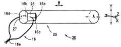
도 1의 (a)는 본 발명의 실시 형태 1에 따른 내시경용 압배체(10)를 도시하는 사시도이다. 도 1의 (b)는 실시 형태 1의 내시경용 압배체(10)가 트로카(71)의 원통 내를 통과하는 모습을 도시하는 단면도이다. 도 2는 이 실시 형태 1의 내시경용 압배체(10)의 압배체 본체(15)가 팽윤한 모습(압배체 본체(15'))을 도시하는 사시도이다.FIG. 1A is a perspective view illustrating the
압배체(10)는 압배체 본체(15)와 조영사(16)로 이루어진다. 압배체 본체(15)는 셀룰로오스 스펀지제이며, 셀룰로오스 스펀지 제조 과정에 있어서의 압출 방향(화살표B)을 길이 방향(Z축 방향)으로 한 단면 정방형의 막대 형상체(200㎜×8㎜×8㎜)이다(또한 도면에서는 편의상, 길이 방향을 짧게 그리고 있음). 압배체 본체(15)는 그 막대 측면측, 즉 길이 방향(화살표 B, Z축 방향)과 교차하는 방향(화살표 A, X축 방향)으로부터, 압축률 10%로 압축된 것이다. 압배체 본체(15)는 상기한 사이즈이기 때문에, 원통 내강 단면의 사이즈가 직경 12㎜인 트로카(내강이 진원임)를 통과시킬 수 있다.The
또한 셀룰로오스 스펀지는, 재생 셀룰로오스법이나 셀룰로오스 용제 용액법 등으로 제조할 수 있다. 예를 들어 특허 제3520511호 공보에 개시된 셀룰로오스 스펀지를 들 수 있다.Moreover, a cellulose sponge can be manufactured by the regenerated cellulose method, the cellulose solvent solution method, etc. For example, the cellulose sponge disclosed in patent 3520511 is mentioned.
구체적으로 압배체 본체(15)의 제조법을 예시한다. 우선 목재 칩 등의 셀룰로오스 원료로부터 비스코스를 얻는다. 이 비스코스에 천연 섬유를 가하고, 또한 결정 망소와 폴리올 화합물, 및 적절하게 계면 활성재를 혼합한다. 얻어진 스펀지 원액을 성형틀 내에 압출해서 충전하고, 가열 응고시킨다. 이것을 상기 압출 방향이 길이 방향(Z축 방향)으로 되도록 해서 두꺼운 스트립 형상(200㎜×8㎜×80㎜)으로 잘라낸다(또한, 상기 압출 방향이 도 1(a)의 화살표 B 방향으로 됨). 이것을 상기 길이 방향의 직교 방향으로 압축하면서(또한 이 압축 방향이 도 1(a)의 화살표 A 방향으로 됨) 건조하고, 상기와 같이 가늘고 긴 막대 형상의 압배체 본체(15)(200㎜×8㎜×8㎜)로 한다.Specifically, the manufacturing method of the press body
조영사(16)는 X선 비 투과성의 수지제 실가닥이며, 구체적으로는, 폴리프로필렌계 수지에 황산바륨을 이겨 넣은 멀티 필라멘트나, 황산바륨을 이겨 넣은 염화비닐 수지나 실리콘계 수지의 실 형상체 등을 들 수 있다.The
조영사(16)는, 상기 막대 형상의 압배체 본체(15)에 있어서의 한쪽 단부측 근방에서, 상기 압축 방향(화살표 A, X축 방향)을 따라 삽입 관통되고, 그리고 결삭되어(결삭부(16e)) 고리 형상으로 되어 있다. 한편 이 조영사(16)의 삽입 관통의 출입구는, 압배체 본체(15)의 측면의 평탄부(15e, 15f)에 있어서의 각각 두께 방향(Y축 방향) 중앙의 위치이다. 조영사(16)의 길이로서는, 압배체 본체(15)가 팽윤한 상태(압배체 본체(15'))를 감안하여(도 2 참조), 약간 긴 것으로 되어 있다.The
이하, 본 실시 형태 1의 압배체(10)의 사용 방법에 대해서, 복강경을 이용한 직장 수술을 예로 들어 설명한다.Hereinafter, the method of using the pressed
우선 환자 체위를 일시적으로 머리를 낮게 한 위치로 하고, 중력에 의해 소장을 상방으로 피하게 한다. 복부에 삽입 장착된 트로카의 통보다, 압배체(10)를, 조영사(16)가 부착되어 있지 않은 측을 선두로 해서 복강 내에 삽입한다. 이때, 도 1(b)에 도시하는 바와 같이, 트로카의 통 내벽(71a)에 대하여 접촉하는 것은 압배체 본체(15)의 코너부(15a, 15b, 15c, 15d)로 되고, 평탄부(15e, 15f)에 있어서의 조영사(16)의 삽입 관통 출입구에서는 간극을 발생한다. 따라서 트로카 통 내벽(71a)과 조영사 삽입 관통 출입구 부분(16a, 16b)이 미끄럼 마찰되지 않는다. 또한 삽입 관통 출입구 부분(16a, 16b)으로부터 연장한 부분(16c, 16d)에 있어서는, 이것을 평탄부(15e, 15f)를 따르게 하도록 함으로써, 트로카 통 내벽(71a)에 끼이지 않는다. 따라서 조영사(16)의 절단의 우려가 작다.First, the position of the patient is temporarily placed with the head lowered, and the small intestine is avoided upward by gravity. The
계속해서 상방으로 피하게 한 소장의 간막 근부 부근에 압배체 본체(15)를 배치하고, 이것에 생리식염수를 부여한다. 그러면, 도 2에 도시하는 바와 같이, 상기 압축이 복원하도록 해서 화살표 A' 방향으로 팽윤해서 커진다(압배체 본체(15'), 팽창 배율:10배). 이와 같이 팽윤한 압배체(10)(대강(200㎜×8㎜×80㎜)에 의해 소장이 압배되므로, 환자 체위를 평탄하게 복귀시켜도 표적 장기의 시야가 확보된다.Subsequently, the pressure-distributor
이상과 같이 본 실시 형태의 압배체(10)에 따르면, 환자 체위를 머리를 낮게 한 위치로 하는 것은 수술 시작의 단계뿐이며, 종래와 같이 수술 중의 전체 시간에 걸쳐 머리를 낮게 한 위치를 유지할 필요는 없다. 따라서, 머리를 낮게 한 위치에 수반하는 혈행 동태에의 악영향을 피할 수 있어, 흉곽 출구 증후군 등의 합병증의 예방도 가능하게 된다.As described above, according to the multiplying
또한 종래의 복강경을 이용한 수술에서는, 소장 등의 장기를 골반으로부터 배제하기 위한 유효한 압배체가 없기 때문에, 극단적인 머리를 낮게 한 위치(트란덴베르그 체위)로 수술이 행하여지는 것이 통상이다. 또한 수술 3~4일 전부터 경비적으로 선단에 벌룬이 부착된 카테터를 삽입해 두고, 이것의 조작에 의해 소장을 골반 내로부터 배제하거나 함으로써, 표적 장기의 시야 확보를 도모하는 등의 학회 보고도 있다. 그러나 어느 쪽의 방법도 환자에게 있어서 부담이 큰 것이었다. 한편, 본 발명의 압배체(10)에 따르면, 이들 방법을 채용하지 않더라도, 장기를 적절하게 압배해서 시야의 확보를 도모하는 것이 가능하게 된다.In the conventional laparoscopic surgery, since there is no effective alveolar body to remove organs such as the small intestine from the pelvis, the operation is usually performed at a position with an extreme head lowered (Trandenberg position). In addition, there are also academic reports such as attempting to secure the field of view of the target organ by inserting a catheter with a balloon at the tip of the distal end 3-4 days prior to surgery and by removing the small intestine from the pelvis. . But either method was a heavy burden on the patient. On the other hand, according to the pressurizing
표적 장기에의 조치가 끝나서 압배가 불필요하게 되면, 복부에 뚫은 절제 장기 취출용 소절개부(절제된 표적 장기를 취출하기 위한 소절개부(소절개창))로부터 본 발명의 압배체(10)를 체외로 취출한다. 또한 육안으로 압배체(10)의 존재를 확인하기 어려운 경우에는, X선 조영을 행하여, 비추어지는 조영사(16)를 단서로 압배체(10)의 체내 잔류의 유무를 확인한다. 그리고 남아 있으면 체외로 취출한다.After the action on the target organ is completed and the pressure is unnecessary, the
또한 수술의 시작 단계에서 소절개부를 형성해서 내시경용 압배체를 체강 내에 넣도록 하면, 내시경용 압배체가 트로카의 통을 삽입 관통 가능한 사이즈일 필요는 없다는 생각도 있을 것이다. 그러나, 소절개부는 통상, 수술의 종반에 형성되기 때문에, 내시경용 압배체만을 넣기 위해서, 수술의 시작 단계에서 소절개부를 형성하는 것은 피하고 싶다고 하는 요망이 있다.In addition, if a small incision is made at the beginning of the operation so that the endoscope abductor is placed in the body cavity, the endoscope abductor does not have to be a size capable of penetrating the trocar barrel. However, since the small incision is usually formed at the end of the operation, there is a desire to avoid the formation of the small incision at the beginning of the operation in order to put only the endoscope pressure accumulator.
상술한 바와 같이 본 발명에서는 이 소절개부를 내시경용 압배체의 취출에 이용하는 것으로 하고, 체강 내에의 삽입은 트로카로부터로 한 것이다.As described above, in the present invention, the small incision is used for the extraction of the endoscope pressurizer, and the insertion into the body cavity is made from the trocar.
<실시 형태 2>≪ Embodiment 2 >
도 3은 본 발명의 실시 형태 2에 따른 내시경용 압배체(20)를 도시하는 사시도이다.Fig. 3 is a perspective view showing the
이 압배체(20)의 압배체 본체(25)는, 전체적인 대략 형상이 원기둥이며, 그 횡단면이 트로카의 원통 내강 단면보다도 작은 것이다. 그리고 압배체 본체(25)의 한쪽단부로부터 그 근방에 걸쳐 절결되고, 평탄부(26, 27)가 형성되고 있다. 이 평탄부(26, 27)는, 압배체 본체(25)의 제조 과정에 있어서의 압축 방향(화살표 A, X축 방향) 측에 있어서, 대향해서 2개소 형성되어 있다. 즉 압배체 본체에 형성되는 2개소의 평탄부(26, 27)는, 막대 형상 압배체 본체의 축심을 중심으로 한 점대칭의 위치 관계로 형성되어 있다. 그리고 이 평탄부(26, 27)의 중간 정도가 조영사(16)의 삽입 관통의 출입구로 되어 있다. 다른 구성은 상기 실시 형태 1과 마찬가지이다.The pressed body
본 실시 형태 2의 압배체(20)에 있어서도, 상기 실시 형태 1과 마찬가지로, 트로카를 통해서 체강 내에 삽입 가능하다. 그리고 체강 내에서 생리식염수 등을 부음으로써, 팽윤해서 커져, 장기를 압배할 수 있다.Also in the pressed
또한 트로카로부터 삽입할 때, 조영사(16)의 삽입 관통 출입구 부분(16a, 16b)은 트로카 통 내벽으로부터 이격되므로, 마찰되어 절단되는 등의 일이 거의 없다. 또한 평탄부(26, 27)는 압배체 본체(25)의 한쪽 단부까지 이르러 있으므로, 삽입 관통 출입구 부분(16a, 16b)으로부터 연장한 부분(16c, 16d)을 이 평탄부(26, 27)를 따르게 하면, 트로카 통 내벽에 끼이는 일이 없다. 따라서 조영사(16)의 절단의 우려가 작다.Further, when inserted from the trocar, the insertion through
<실시 형태 3>≪ Embodiment 3 >
도 4는 본 발명의 실시 형태 3에 따른 내시경용 압배체(30)를 도시하는 사시도이다.Fig. 4 is a perspective view showing the
이 압배체(30)의 압배체 본체(35)는, 전체적인 대략 형상이 사각기둥이며, 그 횡단면이 트로카의 원통 내강 단면보다도 작은 것이다. 그리고 압배체 본체(35)의 제조 과정에 있어서의 압축 방향(화살표 A, X축 방향) 측의 면에, 각각 오목부(36, 37)가 형성되어 있다. 그리고 압배체 본체(35)의 한쪽 단부측 근방에 있어서의 오목부(36, 37)의 개소를 출입구로 해서, 조영사(16)가 삽입 관통되어 있다. 다른 구성은 상기 실시 형태 1과 마찬가지이다.The
본 실시 형태 3의 압배체(30)에 있어서도, 상기 실시 형태 1과 마찬가지로, 트로카를 통해서 체강 내에 삽입 가능하며, 체강 내에서 생리식염수 등을 부음으로써, 팽윤해서 커져, 장기를 압배할 수 있다.Also in the pressed
또한 트로카로부터 삽입할 때, 조영사(16)의 삽입 관통 출입구 부분(16a, 16b)은 트로카 통 내벽으로부터 이격되므로, 마찰되어 절단되는 일이 거의 없다. 또한 삽입 관통 출입구 부분(16a, 16b)으로부터 연장한 부분(16c, 16d)도, 압배체 본체(35)의 사각기둥의 코너부를 피해서 뻗어가도록 하면, 트로카 통 내벽에 끼이는 일이 없다. 따라서 조영사(16)의 절단의 우려가 작다.Further, when inserted from the trocar, the insertion through
<실시 형태 4>≪ Fourth Embodiment >
도 6의 (a)는 본 발명의 실시 형태 4에 따른 프레임이 부착된 압배체(100)를 도시하는 사시도이다. 도 6의 (c)는 프레임이 부착된 압배체(100) 중 압배체(50)를 도시하는 사시도이다. 도 6의 (b)는 프레임이 부착된 압배체(100) 중 프레임(40)을 도시하는 사시도이다. 또한 도 7은 상기 프레임(40)의 정면도이다. 또한 도 1과 동일한 번호를 붙인 개소는, 도 1의 예와 동일한 구성 부분이다.Fig. 6A is a perspective view showing a
내시경용 압배체(50)는, 압배체 본체(45)와 조영사(16)로 이루어진다.The
도 6의 (c)에 도시하는 바와 같이, 압배체(50)의 압배체 본체(45)는 횡단면이 정방형인 막대 형상체(200㎜×6㎜×6㎜)이다. 이 압배체 본체(45)는, 4개의 측면 중 대치하는 2개의 측면(52, 53)으로부터 압축되어 이루어진다(화살표 A, X축 방향). 또한 압배체(50)에 있어서의 다른 구성은 실시 형태 1의 압배체(10)와 동일하다.As shown in FIG.6 (c), the press body
프레임(40)은, 도 6(b)에 도시하는 바와 같이, 장척의 것이며, 길이 방향(Z축 방향)으로 곧장 연장한 좌우 측벽(42, 43)과 저벽(41)을 구비한다. 프레임(40)은, 그 내공으로서 정사각 기둥 형상의 주내공(44)과, 이것에 연속하는 2개의 부내공(47, 48)을 구비한다(아울러 도 7 참조). 부내공(47, 48)은 프레임(40)의 측벽(42, 43)에 형성된 홈의 공간이다. 즉 좌우 측벽(42, 43)에는 길이 방향 전체에 걸친 오목부(홈)(42b, 43b)가 형성되어 있고, 이 오목부(42b, 43b) 내가 상기 부내공(47, 48)으로 된다. 상기 주내공(44)은, 좌우 측벽(42, 43)에 있어서의 지지벽(42a, 42c, 43a, 43c)(오목부(42b, 43b)를 제외한 좌우 측벽 부분)과 저벽(41)에 의해 구성되어 이루어진다. 주내공(44)의 사이즈는 200㎜×6㎜×6㎜이며, 도 6(a)에 도시하는 바와 같이 상기 압배체 본체(45)가 정확히 끼워지는 크기로 되어 있다.As shown in FIG. 6 (b), the
도 6(a)에 도시하는 바와 같이, 프레임이 부착된 압배체(100)는 상기 프레임(40)의 주공부(44)에 압배체 본체(45)를 수용한 것이다. 프레임(40)에 있어서의 좌우 측벽(42, 43)의 지지벽(42a, 42c, 43a, 43c)에 의해, 압배체 본체(45)의 압축 방향(화살표 A, X축 방향)을 지지하도록 되어 있다. 그리고 압배체 본체(45)의 압축 방향(화살표 A)과 교차하는 방향(Y축 방향)의 측면 중 한쪽에는 저벽(41)이 존재하고, 다른 쪽의 측면이 개방되어 있다. 이와 같이 압배체 본체(45)의 하나의 측면이 노출된 상태로 되어 있다.As shown in FIG. 6 (a), the pressed
또한 조영사(16)의 삽입 관통 출입구 부분(16a, 16b)은, 좌우 측벽(43, 42)의 오목부(43b, 42b)가 형성하는 부내공(48, 47)에 위치하고, 또한 이 삽입 관통 출입구 부분(16a, 16b)으로부터 연장한 부분(16c, 16d)에 대해서도 부내공(48, 47)에 위치하도록 되어 있다.In addition, the insertion through
예를 들어 가스 멸균했을 때, 그 처리 과정에 있어서의 수분에 의해 압배체 본체(45)가 압축 방향의 역방향(화살표 A', X축 방향)으로 팽창하려고 하지만, 상기와 같이 프레임이 부착된 압배체(100)에 따르면, 대치한 지지벽(42a, 42c, 43a, 43c)에 의해 팽창이 억제되고, 소정의 사이즈(도시한 한 예에서는 폭 6㎜)를 유지할 수 있다. 또한 보관 시에 있어서, 공기 중의 수분에 의해 압배체 본체(45)가 팽창하려고 해도, 마찬가지로 팽창이 억제된다.For example, when the gas is sterilized, the pressed body
한편, 상기한 바와 같이 프레임(40)은, 압배체 본체(45)에 있어서의 압축 방향과 교차하는 방향(Y축 방향)의 2개의 측면 중 한쪽이 개방되어 있으므로, 이 부분에 있어서 압배체 본체(45)가 멸균 가스에 노출되게 된다. 따라서, 가스 멸균 효과도 확실하게 얻어진다.On the other hand, as mentioned above, since the one side of the two sides of the
상세하게 설명하면, 압배체 본체(45)는 셀룰로오스 스펀지제이므로, 가스 멸균 처리에 있어서는, 멸균 가스(예를 들어 에틸렌옥사이드 가스)가 압배체 본체(45)에 침투하도록 해서 멸균해 간다. 가령 프레임이 압배체 본체(45)의 사방의 측면을 둘러싸는 것이면, 멸균 가스의 통과 길로서는 막대 형상의 압배체 본체(45)의 상하 단부면(6㎜×6㎜)만으로 된다. 이 때문에, 도시한 예와 같이 길이가 200㎜인 막대 형상 압배체 본체(45)의 모두를 멸균하기 위해서는, 멸균 가스가 도달하는 최대 깊이가 200㎜÷2=100㎜으로 된다. 따라서 매우 장시간 멸균 가스에 계속해서 노출시킬 필요가 있다.In detail, since the press body
이 점, 상기 실시 형태 4의 프레임(40)과 같이, 1개의 측면이 개방된 것이면, 이 개방 측면(6㎜×200㎜)으로부터도 멸균 가스가 침투하게 된다. 따라서, 멸균 가스가 도달하는 최대 깊은 개소라도 6㎜의 깊이이기 때문에, 멸균 처리를 단시간에 더욱 확실하게 행할 수 있다.In this regard, as in the
또한 가스 멸균 처리에 있어서는, 당연히, 조영사(16)나 프레임(40)도 포함시켜서 프레임이 부착된 압배체(100) 전체가 멸균된다.In addition, in the gas sterilization process, the
또한 가스 멸균 처리 시에는, 프레임이 부착된 압배체(100)를 가스 투과성의 포장체에 수납하고, 가스 멸균을 실시하는 것이 권장된다. 이 포장체에 수납한 상태에서 수요자에게 제공하고, 사용 직전에 포장체를 개방해서 프레임이 부착된 압배체(100)를 취출하면 된다.In addition, during gas sterilization treatment, it is recommended to store the pressed
다음에 내시경을 이용한 수술에 있어서의 상기 프레임이 부착된 압배체(100)의 사용 방법에 대해서 서술한다. 도 8은 프레임이 부착된 압배체(100)를 트로카(70)에 삽입하는 모습을 도시하는 사시도이다.Next, the use method of the
프레임이 부착된 압배체(100)의, 조영사(16)가 설치되어 있지 않은 측 F를, 트로카의 삽입구 부분(71b)과 서로 맞댄다. 그 다음에 조영사(16)가 설치되어 있는 측 E로부터 청결한 압출 막대(도시하지 않음)로 압배체(50)를 그 장척 방향(Z축 방향)으로 압출한다(화살표C). 그렇게 하면 프레임(40)으로부터 압배체(50)가 빼내져(화살표 D), 트로카(70)의 통내(71c)에 삽입된다.The side F of the pressed
이때, 압배체(50)의 조영사(16)의 삽입 관통 출입구 부분(16a, 16b)이나 거기에서 연장한 부분(16c, 16d)(도 6(c) 참조)은, 길이 방향으로 형성된 부내공(48, 47)(오목부(43b, 42b) 내)을 이동하게 된다(도 6(a) 참조). 따라서, 출입구 부분(16a, 16b)이나 부분(16c, 16d)은, 압배체 본체(45)와 프레임(40)의 내벽면 사이에 끼이거나 마찰되거나 하는 일이 없다. 조영사(16)의 그 밖의 부분(상기 연장한 부분(16c, 16d)으로부터 결삭부(16e)에 이르는 부분)은, 압배체 본체(45)의 후단부면(조영사(16)가 설치되어 있는 측 E의 단부면)보다도 뒤에 위치하게 되므로, 압배체 본체(45)와 프레임(40)의 내벽면에 끼이는 일은 없다(도 6(a), 도 8 참조).At this time, the insertion through-out
또한, 프레임(40)은 트로카의 통내(71c)의 사이즈보다 크므로, 트로카 통내(71c)에는 들어가지 않는다.In addition, since the
이와 같이 해서 트로카(70)의 통내(71c)에 삽입한 압배체(50)를, 상기 실시 형태 1과 마찬가지로 상기 트로카(70)로부터 체강 내에 삽입하고, 생리식염수를 부여해서 팽윤시켜, 장기의 압배에 사용한다.In this way, the pressed
<실시 형태 5>≪ Embodiment 5 >
도 9는 본 발명의 실시 형태 5에 따른 프레임이 부착된 압배체(800)를 도시하는 사시도이다. 또한 도 1과 동일한 번호를 붙인 개소는, 도 1의 예와 동일한 구성 부분이다.Fig. 9 is a perspective view showing a
실시 형태 5의 프레임이 부착된 압배체(800)는, 조영사(16)가 부착된 압배체 본체(15)를 프레임(80)에 수용한 것이다. 프레임(80)은 상부 부재(82)와 하부 부재(81)로 이루어지고, 상부 부재(82)와 하부 부재(81)는 분리 가능하게 되어 있다. 즉 프레임(80)은 그 길이 방향을 따라서 2분할할 수 있는 것이다.The pressed
상부 부재(82) 및 하부 부재(81)는, 모두 단면 ㄷ자 형상이다. 즉 상부 부재(82)에 있어서, 상면부(82b)로부터 지지벽(82a, 82c)이 세워 설치되고, 하부 부재(81)에 있어서, 저면부(81b)로부터 지지벽(81a, 81c)이 세워 설치되어 있다. 그리고 상부 부재(82)의 지지벽(82a, 82c) 및 하부 부재(81)의 지지벽(81a, 81c)이, 압배체 본체(15)의 압축 방향(화살표 A, X축 방향)을 지지한다.The
또한 압배체 본체(15)에 장착한 상태에서 상부 부재(82)와 하부 부재(81) 사이에는 간극(83, 84)이 형성되어 있다. 이 간극(83, 84)의 개소에, 조영사(16)의 삽입 관통 출입구 부분(압배체 본체(15)에의 조영사(16)의 삽입 관통 출입구 부분)이 위치하고, 조영사(16)가 끼이지 않도록 되어 있다.Moreover, the
압배체 본체(15)의 팽창 방향은 오로지 압배체 본체 제조 시에 있어서의 압축 방향(화살표 A)에 대하여 역방향으로 된다. 본 실시 형태 5에 있어서도, 프레임(80)이, 압배체 본체(15)의 압축 방향에 지지벽(82a, 82c, 81a, 81c)을 구비하고 있으므로, 압배체 본체(15)의 팽창을 억제할 수 있다. 따라서 트로카 원통 내강을 삽입 관통 가능한 크기로 유지할 수 있다.The expansion direction of the green body
또한 상기한 바와 같이 간극(개구부)(83, 84)이 프레임(80)의 길이 방향(Z축 방향)의 전체 길이에 걸쳐 형성되어 있으므로, 가스 멸균 처리 시에 멸균 가스가 상기 간극(83, 84)으로부터 압배체 본체(15)에 침투하게 되어, 멸균 처리의 시간이 짧아도 된다.Further, as described above, the gaps (openings) 83 and 84 are formed over the entire length of the
실시 형태 5의 프레임이 부착된 압배체(800)의 사용 시에는, 상부 부재(82)와 하부 부재(81)를 이격시키는 방향(도면의 상하 방향)으로 분리하고, 가운데의 압배체(조영사(16)가 부착된 압배체 본체(15))를 취출한다. 그렇게 해서 상기 압배체를 트로카의 통을 통과시켜 체내에 삽입하고, 상기와 마찬가지로, 생리식염수를 부여해서 팽윤시켜, 압배를 행한다.At the time of use of the
또한 본 실시 형태 5에 있어서도, 프레임이 부착된 압배체(800)의, 조영사(16)가 부착되어 있지 않은 측 F를 트로카의 삽입구 부분과 서로 맞대어, 압배체(압배체 본체(15) 및 조영사(16))를 그 장척 방향(Z축 방향)으로 압출하면서, 트로카의 통 내에 삽입하도록 해도 된다. 이때, 조영사(16)는 길이 방향의 간극(83, 84)을 따라 이동하므로, 끼이거나 마찰되는 일이 없다.In addition, also in this Embodiment 5, the side F of the
<실시 형태 6>≪ Embodiment 6 >
도 10의 (a)는 본 발명의 실시 형태 6에 따른 프레임이 부착된 압배체(900)를 도시하는 사시도이다. (b)는 프레임이 부착된 압배체(900) 중 프레임(93)을 도시하는 사시도이다. (c)는 프레임이 부착된 압배체(900) 중 내시경용 압배체(90)(압배체 본체(91) 및 조영부(92))를 도시하는 사시도이다.FIG. 10A is a perspective view showing a
도 10(c)에 도시하는 바와 같이, 압배체(90)에 있어서의 압배체 본체(91)는, 횡단면이 정방형인 막대 형상체(240㎜×8㎜×8㎜)이다. 이 압배체 본체(91)는, 4개의 측면(91a, 91b, 91c, 91d) 중 대치하는 2개의 측면(91b, 91d)으로부터 압축되어 이루어진다(화살표 A, X축 방향).As shown in FIG.10 (c), the press body
압배체 본체(91)의 측면(91b, 91d)의 중앙에는 길이 방향(Z축 방향)을 따라 조영부(92)가 형성되어 있다. 조영부(92)는, X선 비 투과성의 열융착성 수지제 실가닥을 상기 측면(91b, 91d)에 열 융착한 것이다. 상기 X선 비 투과성의 열융착성 수지제 실가닥으로서는, 예를 들어 폴리프로필렌계 수지에 황산바륨을 이겨 넣은 멀티 필라멘트나, 황산바륨을 이겨 넣은 염화비닐 수지의 실 형상체 등을 들 수 있다.In the center of the
또한 압축측의 측면(91b, 91d)에 한하지 않고, 압축 방향과 직교하는 방향(Y축 방향)의 측면(91a, 91c)에 조영부(92)를 형성해도 된다.In addition, the
프레임(93)은, 도 10(b)에 도시하는 바와 같이, 장척의 것이고, 길이 방향(Z축 방향)으로 곧장 연장한 좌우 측벽(94, 95)과 저벽(96)을 구비한다. 좌우의 측벽(94, 95)은 각각 지지벽(94a, 95a)과, 이들의 상부 테두리로부터 각각 연장된 윙(94b, 95b)으로 구성되어 있다. 지지벽(94a, 95a)과 저벽(96)에 의해 둘러싸인 공간은, 상기 압배체 본체(91)가 정확히 들어가는 크기이다.As shown in FIG. 10 (b), the
프레임(93)의 길이 방향의 일방측에는 설부(97)가 돌출해서 설치되어 있다. 설부(97)는 저벽(96)을 따라 설치되어 있고, 핀(98)을 회전축으로 해서 저벽(96)으로부터 상방으로 기립시킬 수 있게 되어 있다(화살표 G).The
도 10(a)에 도시하는 바와 같이, 프레임이 부착된 압배체(900)는, 프레임(93)의 내공에 압배체(90)를 수용한 것이다. 그리고 프레임(93)의 지지벽(94a, 95a)에 의해, 압배체(90)를 압축 방향(화살표 A)으로부터 지지하여, 압배체(90)가 팽창하지 않도록 하고 있다.As shown in FIG. 10 (a), the
다음으로 실시 형태 6의 프레임이 부착된 압배체(900)의 사용 방법에 대해서 설명한다. 도 11은, 프레임(93)으로부터 압배체(90)를 취출하는 모습을 도시하는 측면도이다.Next, the usage method of the
우선 프레임(93)의 설부(97)를 들어올리고(화살표 G), 이것에 따라 압배체(90)의 한쪽의 단부 부분을 들어올려, 프레임(93)으로부터 노출시킨다. 그리고 이 노출된 끝 부분을 손에 들고, 프레임(93)으로부터 압배체(90)를 취출한다(화살표 H).First, the
이 취출한 압배체(90)(도 10(c) 참조)를, 트로카의 통을 통해 체강(복강이나 흉강)에 삽입한다. 이때, 조영부(92)는, 단면이 직사각형인 압배체 본체(91)의 측면(91b, 91d)의 중앙 부분에 융착되어 있으므로, 조영부(92)의 개소가 트로카의 통 내벽에 대하여 미끄럼 마찰되는 일이 없다. 따라서 조영부(92)가 미끄럼 마찰에 의해 벗겨질 우려가 거의 없다.This taken out body 90 (refer FIG. 10 (c)) is inserted into a body cavity (abdominal cavity or a thoracic cavity) through the trocar barrel. At this time, since the
계속해서 체강 내의 압배체(90)에 생리식염수를 부여해서 팽윤시키고, 이 커진 압배체(90)에 의해 장기를 압배한다.Subsequently, physiological saline is added to the pressed
<실험><Experiment>
본 발명의 압배체 본체에 에틸렌옥사이드 가스 멸균을 실시한 경우의 사이즈 변화에 대해서 실험을 행하였다.An experiment was performed on the size change when ethylene oxide gas sterilization was performed on the main body of the invention.
압배체 본체로서, 압축률 10%에서 건조 압축 성형된 셀룰로오스 스펀지(시료 No.1:200㎜×8㎜×8㎜, 시료 No.2:200㎜×8㎜×6㎜)를 사용하였다. 또한 상기 시료의 압축 전의 사이즈는, 시료 No.1이(200㎜×8㎜×80㎜, 시료 No.2가 200㎜×8㎜×60㎜이며, 시료 No.1, 2는 이들을 두께 방향으로 압축하여(도 1(a), 도 6(c), 도 10(c)에 도시하는 화살표 A 참조), 상기한 사이즈로 한 것이다.As the main body of the compact, a cellulose sponge (sample No. 1: 200 mm × 8 mm × 8 mm, sample No. 2: 200 mm × 8 mm × 6 mm) that was dry compression molded at a compression ratio of 10% was used. In addition, the size before compression of the said sample is Sample No. 1 (200 mm x 8 mm x 80 mm, Sample No. 2 is 200 mm x 8 mm x 60 mm, and Sample No. 1 and 2 have them in thickness direction. Compression (see arrow A shown in FIG. 1 (a), FIG. 6 (c), and FIG. 10 (c)) was made into the size mentioned above.
상기 시료 No.1, 2를 각각 3개씩 멸균 백에 넣어서 에틸렌옥사이드 가스 멸균을 실시하였다. 멸균 시간 4시간, 6시간의 것에 대해서, 각각 멸균 처리 후의 두께 방향의 사이즈를 측정하였다. 또한 이 사이즈 측정 시에, 두께 방향 중 가장 부풀어 오른 개소를 측정하였다. 실험 결과를 하기 표 1에 나타낸다.Ethylene oxide gas sterilization was performed by putting three samples No. 1 and 2 into sterilization bags, respectively. About the thing of sterilization time 4 hours and 6 hours, the size of the thickness direction after sterilization process was measured, respectively. In addition, at the time of this size measurement, the swelling point in the thickness direction was measured. The experimental results are shown in Table 1 below.
sample
Sterilization time (hours)
No.1
No.1
80
80
8
8
4
4
14.83
14.83
185.42
185.42
6
6
14.67
14.67
183.33
183.33
No.2
No.2
60
60
6
6
4
4
18.17
18.17
302.78
302.78
6
6
18.00
18.00
300.00
300.00
표 1로부터 알 수 있는 바와 같이, 어느 쪽의 시료에 있어서도 에틸렌옥사이드 가스 멸균 처리에 의해 팽창이 확인되었다. 이와 같이 팽창하면 트로카의 통에 삽입 관통하기 어려워진다. 그러나 프레임에 압배체 본체를 수용한 상태에서 멸균 처리를 행하면, 팽창을 억제할 수 있으므로, 프레임이 부착된 압배체로 하는 것이 유효하다.As can be seen from Table 1, expansion was confirmed in both samples by ethylene oxide gas sterilization. This expansion makes it difficult to penetrate the trocar's barrel. However, if the sterilization treatment is carried out in the state where the main body of the main body is accommodated in the frame, expansion can be suppressed.
이상, 본 발명에 따른 압배체 및 프레임이 부착된 압배체에 관해서, 예를 나타내는 도면을 참조하면서 구체적으로 설명하였지만, 본 발명은 물론 도시예에 한정되는 것이 아니며, 상기한 취지에 적합할 수 있는 범위로 적당히 변경을 가해서 실시하는 것도 가능하며, 그들은 모두 본 발명의 기술적 범위에 포함된다.As mentioned above, although the pressed body and the pressed body with a frame which concern on this invention were demonstrated concretely with reference to the drawing which shows an example, this invention is not limited to the illustration of course, and may be suitable for the said meaning. It is also possible to carry out by changing suitably in the range, and they are all included in the technical scope of this invention.
예를 들어 상기 실시 형태 4에 있어서는, 압배체 본체(45)의 압축 방향 폭(6㎜)과 동일한 사이즈의 주내공(44)을 구비한 프레임(40)을 설명했지만, 압배체 본체(45)보다도 프레임(40)의 주내공(44)이 큰 것이어도 된다. 단, 프레임(40)의 주내공(44)의 크기로서는, 트로카의 통내(71c)의 크기 이하인 것을 필요로 한다. 압배체 본체(45)가 프레임(40)의 내벽면과 접촉하는 정도로 팽윤해도, 트로카의 통 내에 삽입 관통 가능한 사이즈일 필요가 있기 때문이다.For example, in the said Embodiment 4, although the
또한 상기 실시 형태 4에서는 프레임(40)의 측벽(42, 43)의 홈으로서, 직사각형의 오목부(42b, 43b)의 것을 설명하였지만, 반원형이나 삼각형 등의 홈이어도 된다.In the fourth embodiment,
또한 상기 실시 형태 4의 프레임(40)에 있어서, 저벽(41)이 없는 것(단, 좌우 측벽(42, 43)을 연결하기 위한 프레임을 구비함)으로 해도 된다.In the
또한 예를 들어 상기 실시 형태 4에서는 프레임(40)의 측벽(42, 43)에 홈(오목부(42b, 43b))을 갖는 것을 설명하였지만, 압배체로서, 조영사가 압배체 본체의 측면으로부터 삽입 관통된 것이 아닌 것(예를 들어 조영사가 막대 형상 압배체 본체의 축을 따라 삽입 관통된 것이나, 조영사를 압배체 본체의 측면에 열 융착한 것, 조영사 대신에 RFID 태그를 압배체 본체에 부착해서 잔류 방지를 도모한 것 등)을 사용한 경우에는, 상기 프레임으로서는 상기 홈이 없는 것이어도 된다(예를 들어 실시 형태 6).For example, in Embodiment 4, it has been described that the grooves (
게다가 프레임의 측벽으로서는, 압배체의 팽창을 방지할 수 있는 것이면, 도 6 내지 도 9에 도시하는 바와 같은 구멍이 없는 판 형상물에 한정하는 것이 아니라, 예를 들어 구멍을 복수 설치한 판이나 메쉬 형상의 판 등이어도 된다.In addition, the side wall of the frame is not limited to a plate-shaped object without holes as shown in Figs. 6 to 9 as long as the expansion body can be prevented from expanding. May be used.
상기 실시 형태 1 내지 6에서는 압축 방향이 화살표 A 방향(X축 방향)만의 것을 설명하였지만, 상하 좌우(X축 방향 및 Y축 방향)로부터 압축한 것이어도 된다. 그때, 프레임으로서는 이들의 압축 방향에 대응한 측벽을 구비한 것으로 하면 된다.Although the compression direction demonstrated only the arrow A direction (X-axis direction) in the said Embodiment 1-6, what compressed from the up-down left-right (X-axis direction and Y-axis direction) may be sufficient. In that case, what is necessary is just to have a side wall corresponding to these compression directions as a frame.
10, 20, 30, 50, 90 : 내시경용 압배체
15, 25, 35, 45, 91 : 압배체 본체
15e, 15f, 26, 27 : 평탄부
16 : 조영사
16a, 16b : 조영사 삽통 출입구 부분
36, 37 : 오목부
40, 80, 93 프레임
41, 42, 43, 94, 95 : 측벽
42a, 42c, 43a, 43c, 81a, 81c, 82a, 82c, 94a, 95a :지지벽
42b, 43b : 오목부(홈)
44 : 주내공
47, 48 : 부내공
70 : 트로카
71a : 트로카 통 내벽
92 : 조영부
97 : 설부
98 : 핀
100, 800, 900 : 프레임이 부착된 압배체
10, 20, 30, 50, 90: endoscopes
15, 25, 35, 45, 91: green body
15e, 15f, 26, 27: flat part
16: Consul
16a, 16b: Contrast insertion gate entrance part
36, 37: recess
40, 80, 93 frames
41, 42, 43, 94, 95: sidewalls
42a, 42c, 43a, 43c, 81a, 81c, 82a, 82c, 94a, 95a: support wall
42b, 43b: recessed part (groove)
44: inside the ball
47, 48: buoyong
70: trocar
71a: Trocar barrel inner wall
92: contrast department
97: tongue
98: pin
100, 800, 900: Green plate with frame
Claims (14)
Translated fromKorean건조와 압축 성형함으로써 얻어진 흡수 팽창성 재료로 구성된 압배체 본체를 구비하고,
상기 압배체 본체는, 체외로부터의 조작용 지지 부재를 구비하지 않고, 막대 형상이며 그 횡단면이 상기 트로카의 원통 내강 단면보다도 작고, 흡액에 의해 체강 내에서 팽창하여 커지는 것에 의해 표적 근방의 장기를 압배하는 것을 특징으로 하는, 내시경용 압배체.It is used in endoscopic surgery, it is a rolling medium inserted into the body cavity through the trocar,
It is provided with the main body which consists of the absorption expandable material obtained by drying and compression molding,
The main body of the pressure-distributing body does not have an operation support member from outside the body, and has a rod shape, the cross section of which is smaller than the cross section of the cylindrical lumen of the trocar, and expands and expands in the body cavity by the liquid absorption, thereby increasing the organ near the target. An endoscope rolling body, characterized in that for rolling.
상기 압배체 본체의 압축 방향과 직교하는 면에 상기 Z축 방향을 따라서 쌍으로 되어 대치하는 지지벽을 갖는, 내시경용 압배체.The long frame according to claim 1 or 2, further comprising: a long frame for accommodating the pressed body main body in a removable manner;
An endoscope accumulator having a support wall that is paired and opposed in the Z-axis direction on a surface orthogonal to the compression direction of the accumulator body.
상기 압배체 본체의 압축 방향이 상기 X축 방향이며, 상기 프레임이, 상기 Y축 방향의 적어도 일방측을 개방한 것인, 내시경용 압배체.The method according to claim 3, wherein when two directions orthogonal to the Z axis direction are used as the X axis direction and the Y axis direction,
The compression direction of the said main body of a main body is the said X-axis direction, The said end frame is a high pressure end body which opened at least one side of the said Y-axis direction.
상기 설부가, 상기 저벽으로부터 Z축 방향의 일방측으로 돌출해서 이루어지고, 상기 Y축 방향의 개방측에 기립 가능하게 구성되어 있는, 내시경용 압배체.6. The frame according to claim 5, wherein the frame includes a bottom wall on the other side in the Y-axis direction, and a tongue along the inner wall surface is provided on at least a portion of the inner wall surface of the bottom wall.
The end tongue is formed by protruding from the bottom wall toward one side in the Z-axis direction, and configured to stand on the opening side in the Y-axis direction.
상기 압출 방향을 Z축 방향, 이것과 직교하는 2개의 방향을 X축 방향 및 Y축 방향으로 했을 때, 상기 셀룰로오스 스펀지가, X축 방향과 Y축 방향 중 하나 이상의 방향으로 압축된 것인, 내시경용 압배체.The said rod-shaped pressed body main body of Claim 8 cut out so that the longitudinal direction might become an extrusion direction in the manufacturing process of the said cellulose sponge,
When the said extrusion direction is made into the Z-axis direction and two directions orthogonal to this are the X-axis direction and the Y-axis direction, the said cellulose sponge is the thing compressed by one or more directions of an X-axis direction and a Y-axis direction. Solvents.
상기 압배체 본체에는, 그 길이 방향을 따른 측면에 평탄부 또는 오목부 중 어느 한쪽 또는 양쪽이 합계 2개소 형성되고, 상기 평탄부 또는 오목부를 통해서 상기 조영사가 삽입 관통되어 있는, 내시경용 압배체.4. The method according to claim 3, wherein the contrast medium is inserted through and finished in the pressed body body,
The endoscope main body, in which the one side or both sides of a flat part or a recessed part are formed in the said main body main body in the longitudinal direction along the longitudinal direction, and the said contrast medium penetrates through the said flat part or the recessed part.
Applications Claiming Priority (3)
| Application Number | Priority Date | Filing Date | Title |
|---|---|---|---|
| JPJP-P-2008-223986 | 2008-09-01 | ||
| JP2008223986 | 2008-09-01 | ||
| PCT/JP2009/064777WO2010024244A1 (en) | 2008-09-01 | 2009-08-25 | Endoscope excluder |
Publications (2)
| Publication Number | Publication Date |
|---|---|
| KR20110053229A KR20110053229A (en) | 2011-05-19 |
| KR101353192B1true KR101353192B1 (en) | 2014-01-17 |
Family
ID=41721412
Family Applications (1)
| Application Number | Title | Priority Date | Filing Date |
|---|---|---|---|
| KR1020117004683AExpired - Fee RelatedKR101353192B1 (en) | 2008-09-01 | 2009-08-25 | Endoscope excluder |
Country Status (5)
| Country | Link |
|---|---|
| EP (1) | EP2332469B1 (en) |
| JP (1) | JP5128672B2 (en) |
| KR (1) | KR101353192B1 (en) |
| ES (1) | ES2544825T3 (en) |
| WO (1) | WO2010024244A1 (en) |
Families Citing this family (5)
| Publication number | Priority date | Publication date | Assignee | Title |
|---|---|---|---|---|
| CN102791202B (en)* | 2010-03-08 | 2015-05-27 | 川本产业株式会社 | Compression body for surgery |
| JP5739660B2 (en)* | 2010-12-27 | 2015-06-24 | オオサキメディカル株式会社 | Exclusion body for endoscopic surgery |
| JP2012152236A (en)* | 2011-01-21 | 2012-08-16 | Kawamoto Sangyo Kk | Spacer |
| JP5674545B2 (en)* | 2011-04-22 | 2015-02-25 | オオサキメディカル株式会社 | Liver lifting pressure relief device |
| EP3146906A4 (en) | 2014-05-19 | 2017-11-22 | Toray Fine Chemicals Co., Ltd. | Excluder |
Citations (1)
| Publication number | Priority date | Publication date | Assignee | Title |
|---|---|---|---|---|
| KR960004969B1 (en)* | 1990-07-24 | 1996-04-18 | 윤인배 | Multifunctional devices for endoscopic surgical procedures |
Family Cites Families (10)
| Publication number | Priority date | Publication date | Assignee | Title |
|---|---|---|---|---|
| US3961629A (en)* | 1968-06-11 | 1976-06-08 | American Cyanamid Company | Using hydrophilic polyurethane laparotomy sponges |
| US6120437A (en)* | 1988-07-22 | 2000-09-19 | Inbae Yoon | Methods for creating spaces at obstructed sites endoscopically and methods therefor |
| US5074840A (en)* | 1990-07-24 | 1991-12-24 | Inbae Yoon | Packing device and method of packing for endoscopic procedures |
| JPH07116262A (en)* | 1993-10-22 | 1995-05-09 | Olympus Optical Co Ltd | Expanding body for medical treatment |
| US5466231A (en)* | 1993-11-04 | 1995-11-14 | Merocel Corporation | Laminated sponge device |
| JP3520511B2 (en) | 2000-09-04 | 2004-04-19 | 株式会社ホギメディカル | Method for producing wound-absorbent covering protective material using cellulose sponge |
| JP4033327B2 (en) | 2001-11-30 | 2008-01-16 | 株式会社八光 | Retractor |
| JP2005253916A (en) | 2004-03-10 | 2005-09-22 | Shigehisa Yanagimoto | Balloon type supporting forceps using carbon dioxide injection for abdominal surgery with small visual field such as laparoscopy, extrasomatic method or the like |
| CA2833585C (en)* | 2005-04-29 | 2017-06-20 | Cook Biotech Incorporated | Volumetric grafts for treatment of fistulae and related methods and systems |
| JP2009089900A (en)* | 2007-10-09 | 2009-04-30 | Toray Fine Chemicals Co Ltd | Member for exclusion in surgery |
- 2009
- 2009-08-25KRKR1020117004683Apatent/KR101353192B1/ennot_activeExpired - Fee Related
- 2009-08-25JPJP2010526715Apatent/JP5128672B2/enactiveActive
- 2009-08-25WOPCT/JP2009/064777patent/WO2010024244A1/enactiveApplication Filing
- 2009-08-25ESES09809895.7Tpatent/ES2544825T3/enactiveActive
- 2009-08-25EPEP09809895.7Apatent/EP2332469B1/enactiveActive
Patent Citations (1)
| Publication number | Priority date | Publication date | Assignee | Title |
|---|---|---|---|---|
| KR960004969B1 (en)* | 1990-07-24 | 1996-04-18 | 윤인배 | Multifunctional devices for endoscopic surgical procedures |
Also Published As
| Publication number | Publication date |
|---|---|
| ES2544825T3 (en) | 2015-09-04 |
| EP2332469B1 (en) | 2015-05-27 |
| JP5128672B2 (en) | 2013-01-23 |
| JPWO2010024244A1 (en) | 2012-01-26 |
| EP2332469A1 (en) | 2011-06-15 |
| KR20110053229A (en) | 2011-05-19 |
| EP2332469A4 (en) | 2011-09-28 |
| WO2010024244A1 (en) | 2010-03-04 |
Similar Documents
| Publication | Publication Date | Title |
|---|---|---|
| ES2270594T3 (en) | DEVICE TO FACILITATE THE HEMOSTASIS OF A BIOPSY SECTION. | |
| JP4391699B2 (en) | Hemostatic agent insertion device | |
| JP4728547B2 (en) | Apparatus and method for promoting hemostasis in a biopsy tract | |
| KR101353192B1 (en) | Endoscope excluder | |
| JP2649286B2 (en) | Surgical sheath with medical tubular device | |
| EP2578167A1 (en) | Surgical retractor | |
| EP2133031A1 (en) | Stabilization assist device for trocar | |
| JP6012428B2 (en) | Hemostasis balloon unit | |
| US10945747B2 (en) | System for treating an epistaxis | |
| JP5157689B2 (en) | Endoscopic surgery device | |
| JP2012512112A (en) | Endoscope sheet rolling device | |
| KR20100110844A (en) | Organ spacer for scope-assisted surgery | |
| US20090270911A1 (en) | Vessel Sealing Device and Method of Using Same | |
| US20130226029A1 (en) | Two-part access port | |
| KR20170007725A (en) | Excluder | |
| JP4706015B2 (en) | Disposable fabric inserter | |
| KR20220091006A (en) | Lifting device for plastic surgery | |
| US20120232581A1 (en) | Tamponade for Biopsy Surgery and Method of Operation | |
| JP5313394B2 (en) | Surgical exclusion body | |
| JP5418883B2 (en) | Endoscopic surgery device | |
| CN119214722A (en) | A blocking system | |
| CN119949951A (en) | A disposable hematoma removal device | |
| KR20220091007A (en) | Lifting device for plastic surgery | |
| JP2008029675A (en) | Balloon catheter |
Legal Events
| Date | Code | Title | Description |
|---|---|---|---|
| PA0105 | International application | St.27 status event code:A-0-1-A10-A15-nap-PA0105 | |
| P11-X000 | Amendment of application requested | St.27 status event code:A-2-2-P10-P11-nap-X000 | |
| P13-X000 | Application amended | St.27 status event code:A-2-2-P10-P13-nap-X000 | |
| PG1501 | Laying open of application | St.27 status event code:A-1-1-Q10-Q12-nap-PG1501 | |
| A201 | Request for examination | ||
| PA0201 | Request for examination | St.27 status event code:A-1-2-D10-D11-exm-PA0201 | |
| E902 | Notification of reason for refusal | ||
| PE0902 | Notice of grounds for rejection | St.27 status event code:A-1-2-D10-D21-exm-PE0902 | |
| T11-X000 | Administrative time limit extension requested | St.27 status event code:U-3-3-T10-T11-oth-X000 | |
| P11-X000 | Amendment of application requested | St.27 status event code:A-2-2-P10-P11-nap-X000 | |
| P13-X000 | Application amended | St.27 status event code:A-2-2-P10-P13-nap-X000 | |
| E90F | Notification of reason for final refusal | ||
| PE0902 | Notice of grounds for rejection | St.27 status event code:A-1-2-D10-D21-exm-PE0902 | |
| T11-X000 | Administrative time limit extension requested | St.27 status event code:U-3-3-T10-T11-oth-X000 | |
| P11-X000 | Amendment of application requested | St.27 status event code:A-2-2-P10-P11-nap-X000 | |
| P13-X000 | Application amended | St.27 status event code:A-2-2-P10-P13-nap-X000 | |
| E701 | Decision to grant or registration of patent right | ||
| PE0701 | Decision of registration | St.27 status event code:A-1-2-D10-D22-exm-PE0701 | |
| GRNT | Written decision to grant | ||
| PR0701 | Registration of establishment | St.27 status event code:A-2-4-F10-F11-exm-PR0701 | |
| PR1002 | Payment of registration fee | St.27 status event code:A-2-2-U10-U12-oth-PR1002 Fee payment year number:1 | |
| PG1601 | Publication of registration | St.27 status event code:A-4-4-Q10-Q13-nap-PG1601 | |
| R18-X000 | Changes to party contact information recorded | St.27 status event code:A-5-5-R10-R18-oth-X000 | |
| FPAY | Annual fee payment | Payment date:20161221 Year of fee payment:4 | |
| PR1001 | Payment of annual fee | St.27 status event code:A-4-4-U10-U11-oth-PR1001 Fee payment year number:4 | |
| PR1001 | Payment of annual fee | St.27 status event code:A-4-4-U10-U11-oth-PR1001 Fee payment year number:5 | |
| PR1001 | Payment of annual fee | St.27 status event code:A-4-4-U10-U11-oth-PR1001 Fee payment year number:6 | |
| PR1001 | Payment of annual fee | St.27 status event code:A-4-4-U10-U11-oth-PR1001 Fee payment year number:7 | |
| PR1001 | Payment of annual fee | St.27 status event code:A-4-4-U10-U11-oth-PR1001 Fee payment year number:8 | |
| PR1001 | Payment of annual fee | St.27 status event code:A-4-4-U10-U11-oth-PR1001 Fee payment year number:9 | |
| PC1903 | Unpaid annual fee | St.27 status event code:A-4-4-U10-U13-oth-PC1903 Not in force date:20230114 Payment event data comment text:Termination Category : DEFAULT_OF_REGISTRATION_FEE | |
| PC1903 | Unpaid annual fee | St.27 status event code:N-4-6-H10-H13-oth-PC1903 Ip right cessation event data comment text:Termination Category : DEFAULT_OF_REGISTRATION_FEE Not in force date:20230114 |