KR101352799B1 - Diagnostic probe and inspection apparatus having the same - Google Patents
Diagnostic probe and inspection apparatus having the sameDownload PDFInfo
- Publication number
- KR101352799B1 KR101352799B1KR20120049956AKR20120049956AKR101352799B1KR 101352799 B1KR101352799 B1KR 101352799B1KR 20120049956 AKR20120049956 AKR 20120049956AKR 20120049956 AKR20120049956 AKR 20120049956AKR 101352799 B1KR101352799 B1KR 101352799B1
- Authority
- KR
- South Korea
- Prior art keywords
- tube
- cylinder
- vibration
- steering wire
- diagnostic probe
- Prior art date
- Legal status (The legal status is an assumption and is not a legal conclusion. Google has not performed a legal analysis and makes no representation as to the accuracy of the status listed.)
- Expired - Fee Related
Links
Images


Classifications
- A—HUMAN NECESSITIES
- A61—MEDICAL OR VETERINARY SCIENCE; HYGIENE
- A61B—DIAGNOSIS; SURGERY; IDENTIFICATION
- A61B5/00—Measuring for diagnostic purposes; Identification of persons
- A61B5/0059—Measuring for diagnostic purposes; Identification of persons using light, e.g. diagnosis by transillumination, diascopy, fluorescence
- A61B5/0082—Measuring for diagnostic purposes; Identification of persons using light, e.g. diagnosis by transillumination, diascopy, fluorescence adapted for particular medical purposes
- A61B5/0084—Measuring for diagnostic purposes; Identification of persons using light, e.g. diagnosis by transillumination, diascopy, fluorescence adapted for particular medical purposes for introduction into the body, e.g. by catheters
- A—HUMAN NECESSITIES
- A61—MEDICAL OR VETERINARY SCIENCE; HYGIENE
- A61B—DIAGNOSIS; SURGERY; IDENTIFICATION
- A61B5/00—Measuring for diagnostic purposes; Identification of persons
- A61B5/05—Detecting, measuring or recording for diagnosis by means of electric currents or magnetic fields; Measuring using microwaves or radio waves
- A61B5/053—Measuring electrical impedance or conductance of a portion of the body
- A61B5/0538—Measuring electrical impedance or conductance of a portion of the body invasively, e.g. using a catheter
- A—HUMAN NECESSITIES
- A61—MEDICAL OR VETERINARY SCIENCE; HYGIENE
- A61B—DIAGNOSIS; SURGERY; IDENTIFICATION
- A61B5/00—Measuring for diagnostic purposes; Identification of persons
- A61B5/45—For evaluating or diagnosing the musculoskeletal system or teeth
- A61B5/4514—Cartilage
- A—HUMAN NECESSITIES
- A61—MEDICAL OR VETERINARY SCIENCE; HYGIENE
- A61B—DIAGNOSIS; SURGERY; IDENTIFICATION
- A61B5/00—Measuring for diagnostic purposes; Identification of persons
- A61B5/45—For evaluating or diagnosing the musculoskeletal system or teeth
- A61B5/4538—Evaluating a particular part of the muscoloskeletal system or a particular medical condition
- A61B5/4566—Evaluating the spine
- A—HUMAN NECESSITIES
- A61—MEDICAL OR VETERINARY SCIENCE; HYGIENE
- A61B—DIAGNOSIS; SURGERY; IDENTIFICATION
- A61B5/00—Measuring for diagnostic purposes; Identification of persons
- A61B5/68—Arrangements of detecting, measuring or recording means, e.g. sensors, in relation to patient
- A61B5/6846—Arrangements of detecting, measuring or recording means, e.g. sensors, in relation to patient specially adapted to be brought in contact with an internal body part, i.e. invasive
- A61B5/6847—Arrangements of detecting, measuring or recording means, e.g. sensors, in relation to patient specially adapted to be brought in contact with an internal body part, i.e. invasive mounted on an invasive device
- A61B5/6848—Needles
- A—HUMAN NECESSITIES
- A61—MEDICAL OR VETERINARY SCIENCE; HYGIENE
- A61M—DEVICES FOR INTRODUCING MEDIA INTO, OR ONTO, THE BODY; DEVICES FOR TRANSDUCING BODY MEDIA OR FOR TAKING MEDIA FROM THE BODY; DEVICES FOR PRODUCING OR ENDING SLEEP OR STUPOR
- A61M25/00—Catheters; Hollow probes
- A61M25/0067—Catheters; Hollow probes characterised by the distal end, e.g. tips
- A61M25/0082—Catheter tip comprising a tool
Landscapes
- Health & Medical Sciences (AREA)
- Life Sciences & Earth Sciences (AREA)
- Public Health (AREA)
- Engineering & Computer Science (AREA)
- Veterinary Medicine (AREA)
- General Health & Medical Sciences (AREA)
- Animal Behavior & Ethology (AREA)
- Biophysics (AREA)
- Heart & Thoracic Surgery (AREA)
- Biomedical Technology (AREA)
- Medical Informatics (AREA)
- Pathology (AREA)
- Surgery (AREA)
- Physics & Mathematics (AREA)
- Molecular Biology (AREA)
- Orthopedic Medicine & Surgery (AREA)
- Oral & Maxillofacial Surgery (AREA)
- Dentistry (AREA)
- Rheumatology (AREA)
- Physical Education & Sports Medicine (AREA)
- Nuclear Medicine, Radiotherapy & Molecular Imaging (AREA)
- Radiology & Medical Imaging (AREA)
- Pulmonology (AREA)
- Anesthesiology (AREA)
- Hematology (AREA)
- Ultra Sonic Daignosis Equipment (AREA)
Abstract
Translated fromKorean
Description
Translated fromKorean본 발명은 진단용 프로브 및 이를 갖는 검사장치에 관한 것으로서, 보다 상세하게는 프로브 선단의 반경 또는 축방향으로의 이동을 정밀하게 제어함과 아울러, 반경 또는 축방향으로의 진동을 가능하게하고, 체내의 세포조직을 실시간으로 검사할 수 있는 진단용 프로브 및 이를 갖는 검사장치에 관한 것이다.
The present invention relates to a diagnostic probe and an inspection apparatus having the same, and more particularly to precisely control the radial or axial movement of the tip of the probe, and to enable vibration in the radial or axial direction, The present invention relates to a diagnostic probe capable of inspecting cell tissues in real time and a test apparatus having the same.
일반적으로, 디스크 성 통증 진단을 위한 기존의 디스크 자극 검사를 실시하는 경우, 디스크 내부로 삽입된 프로브를 통하여 조영제를 주입한다.In general, when a conventional disc stimulation test for diagnosing pain in the disc, contrast medium is injected through a probe inserted into the disc.
상기와 같은 압력을 높여 통증을 유발시키는 방법은 디스크의 퇴행성이 심한 환자의 경우, 조영제가 디스크 외부로 유출되므로 사용하기 어렵다.The method of causing the pain by raising the pressure is difficult to use because the contrast agent is leaked to the outside of the disc in patients with severe degeneration of the disc.
상기 검사 방법으로는 병변으로 의심되는 부분에 위치한 미세신경 부위만을 자극할 수 없는 문제점을 갖는다.The test method has a problem that can not stimulate only the micro-neural site located in the suspected lesion.
또한, 종래의 인체 삽입용 프로브의 방향을 제어하는 경우, 튜브 끝에 스티어링 와이어(steering wire)의 한쪽 끝을 연결하고, 상기 와이어의 다른 한쪽 끝에 연결한 핸들을 시술자가 조정하여 프로브 끝을 움직인다.In addition, in the case of controlling the direction of a conventional human insertion probe, one end of the steering wire (steering wire) is connected to the end of the tube, and the operator adjusts the handle connected to the other end of the wire to move the probe end.
이때 프로브의 방향제어시 반경 방향 경로의 이동이 정밀하지 못한 문제점이 있다.At this time, there is a problem in that the movement of the radial path is not precise during the direction control of the probe.
본 발명과 관련된 선행문헌으로는 대한민국 공개특허 공개번호 제10-2010-0119907호가 있으며, 상기 선행문헌에는 프로브 끝에 압전 진동체를 구비함으로써 프로브를 간소화하는 기술이 개시된다.
Prior art related to the present invention is Korean Patent Laid-Open Publication No. 10-2010-0119907, which discloses a technique for simplifying a probe by providing a piezoelectric vibrator at the end of the probe.
본 발명의 목적은, 프로브 선단의 반경 또는 축방향으로의 이동을 정밀하게 제어함과 아울러, 반경 또는 축방향으로의 진동을 가능하게하고, 체내의 세포조직을 실시간으로 검사할 수 있는 진단용 프로브 및 이를 갖는 검사장치를 제공함에 있다.SUMMARY OF THE INVENTION An object of the present invention is to provide a diagnostic probe capable of precisely controlling the movement of the tip of a probe in the radial or axial direction, enabling vibration in the radial or axial direction, and real-time inspection of cellular tissue in the body; An inspection apparatus having the same is provided.
본 발명의 다른 목적은, 프로브의 이동이 시술자가 원하는 반경 방향의 경로를 정밀하게 유지하고, 회전형 또는 선형 모터와 같은 모터를 사용하여 프로브 끝을 진동시켜 병변 주위를 자극함으로써 진단할 수 있도록 하며, 진동의 주파수 및 진폭은 조정이 가능하며, 반경방향 또는 축방향으로 진동시킬 수 있는 진단용 프로브 및 이를 갖는 검사장치를 제공함에 있다.
Another object of the present invention is to allow the movement of the probe to precisely maintain the radial path desired by the operator and to diagnose by vibrating the probe tip by vibrating the tip of the probe using a motor such as a rotary or linear motor. In addition, the frequency and amplitude of the vibration is adjustable, and to provide a diagnostic probe and a test apparatus having the same that can vibrate in the radial or axial direction.
일 양태에 있어서, 본 발명은 일정 길이의 튜브와; 양단이 외부에 노출되도록 상기 튜브에 끼워져 설치되는 변형 가능한 실린더와; 중공 형상으로 형성되고, 상기 튜브의 외측 둘레를 감싸도록 배치되는 일정 길이의 가이드 니들과; 상기 튜브의 단부와 연결되며, 외부로부터 동력을 전달 받아 상기 튜브를 반경 방향을 따라 위치시키거나 왕복 이동시키는 방향 제어부와; 외부로부터 동력을 전달 받아 상기 실린더를 축방향을 따라 진동시키는 진동 발생부; 및 상기 튜브의 단부와 연결되며, 상기 방향 제어부와 상기 진동 발생부와 연결되는 손잡이 부를 포함하는 진단용 프로브를 제공한다.In one aspect, the invention is a tube of a certain length; A deformable cylinder fitted to the tube so that both ends thereof are exposed to the outside; A guide needle having a hollow shape and disposed to surround the outer circumference of the tube; A direction control unit connected to an end of the tube and configured to receive or transmit power from the outside to position or reciprocate the tube along a radial direction; Vibration generating unit for receiving the power from the outside to vibrate the cylinder in the axial direction; And a handle part connected to an end portion of the tube and connected to the direction control part and the vibration generating part.
상기 방향 제어부는, 상기 가이드 니들을 관통하며, 일단이 상기 튜브와 연결되는 일정 길이의 스티어링 와이어와, 상기 스티어링 와이어의 타단에 연결되며, 상기 스트어링 와이어를 당기도록 회전되는 회전체를 구비한다.The direction control unit includes a steering wire having a predetermined length connected through the guide needle, one end of which is connected to the tube, and a rotating body connected to the other end of the steering wire and rotating to pull the steering wire.
상기 스티어링 와이어는, 다수의 쌍을 이루어 상기 가이드 니들을 관통하도록 설치되며, 상기 다수의 쌍을 이루는 스티어링 와이어는 서로 180도 간격을 이루어 설치된다.The steering wires are provided in a plurality of pairs so as to penetrate the guide needles, and the plurality of pairs of steering wires are provided with a space of 180 degrees from each other.
상기 회전체는, 상기 스티어링 와이어의 타단이 연결되어, 상기 스티어링 와이어를 당기도록 회전되는 회전 핸들인 것이 좋다.The rotating body is connected to the other end of the steering wire, it is preferable that the rotating handle is rotated to pull the steering wire.
상기 회전체는, 상기 스티어링 와이어의 타단과 연결되며, 외부로부터 동력을 전달 받아, 상기 튜브를 반경 방향을 따라 일정의 진동을 발생시키는 회전 모터일 수도 있다.The rotating body may be connected to the other end of the steering wire and may be a rotating motor that receives power from the outside and generates a predetermined vibration along the radial direction of the tube.
상기 진동 발생부는, 상기 실린더의 타단에 연결되며, 축방향을 따라 상기 실린더를 진동시키는 진동 모터와, 상기 진동 모터의 작동을 제어하며, 상기 진동에 요구되는 진동값이 가변 설정되는 것이 바람직하다.The vibration generating unit is connected to the other end of the cylinder, the vibration motor for vibrating the cylinder along the axial direction, and controls the operation of the vibration motor, it is preferable that the vibration value required for the vibration is set variable.
상기 손잡이 부에는, 상기 진동 모터를 측방향을 따라 슬라이딩 이동 위치시킬 수 있는 이동 부재가 더 구비될 수 있다.The handle part may further include a moving member for slidingly moving the vibration motor in a lateral direction.
상기 가이드 니들에는, 일정의 고정력을 형성하는 적어도 하나 이상의 스티프닝 와이어가 설치되는 것이 바람직하다.Preferably, the guide needle is provided with at least one stiffening wire to form a fixed fixing force.
상기 스티어링 와이어는 금속재질의 원형 와이어 또는 판 스프링 중 어느 하나인 것이 바람직하다.The steering wire is preferably any one of a metal round wire or a leaf spring.
상기 실린더는 금속재질의 와이어 또는 광섬유 중 어느 하나로 형성되는 것이 바람직하다.The cylinder is preferably formed of any one of a metal wire or an optical fiber.
상기 광섬유는 플라스틱 광섬유인 것이 바람직하다.
It is preferable that the optical fiber is a plastic optical fiber.
다른 양태에 있어서, 본 발명은 상기 진단용 프로브와; 상기 실린더의 단부에 설치되며, 디스크의 정상부위와 병변부위의 임피던스를 측정하는 전기 센서 및 광신호를 측정하는 광학적 센서를 갖는 센서부; 및 상기 실린더를 통해 상기 측정되는 결과를 저장하는 저장부를 포함하는 검사장치를 제공한다.
In another aspect, the present invention provides a diagnostic probe; A sensor unit installed at an end of the cylinder, the sensor unit having an electrical sensor measuring an impedance of a top portion and a lesion portion of a disk and an optical sensor measuring an optical signal; And a storage unit for storing the measured result through the cylinder.
본 발명은 정밀한 반경방향 스티어링은 인체 조직의 파괴를 최소화할 수 있으며, 또한 환자의 병변 부위라고 의심되는 곳에 프로브를 신속하게 이동시킬 수 있으므로 진단에 걸리는 시간을 줄일 수 있는 효과를 갖는다.According to the present invention, precise radial steering can minimize the destruction of human tissue, and can also move the probe to a place where the patient is suspected to have a lesion, thereby reducing the time required for diagnosis.
또한, 본 발명은 프로브 끝부분에 위치한 실린더를 원하는 방향, 주파수 및 진폭으로 진동시킬 수 있으며, 진동용 전기모터는 튜브의 바깥쪽 (인체 외부)에 위치하기 때문에 설계제작 및 안전성 관점에서 유리한 효과를 갖는다.In addition, the present invention can vibrate the cylinder located at the end of the probe in the desired direction, frequency and amplitude, the vibration electric motor is located on the outside of the tube (outside the human body) has an advantageous effect in terms of design and safety Have
또한, 본 발명은 전기적 센서와 광섬유를 통한 광학적 센서를 동시에 구현하여 진단의 정확성을 높일 수 있는 효과를 갖는다.In addition, the present invention has the effect of increasing the accuracy of the diagnosis by implementing the electrical sensor and the optical sensor through the optical fiber at the same time.
또한, 본 발명은 검사정보의 실시간 모니터링으로 시술자의 진단에 도움을 줄 수 있고, 검사정보의 저장함으로써 추후 검사정보를 분석할 수 있는 효과를 갖는다.
In addition, the present invention can help the diagnosis of the operator by real-time monitoring of the inspection information, and has the effect of analyzing the inspection information later by storing the inspection information.
도 1은 본 발명의 진단용 프로브의 바람직한 예를 보여주는 도면이다.
도 2는 본 발명의 진단용 프로브의 다른 예를 보여주는 도면이다.
도 3a 내지 도 3d는 휘어짐이 가능한 튜브의 개념도를 보여주는 개면도이다.
도 4는 본 발명의 진단용 프로브를 갖는 검사 장치를 보여주는 도면이다.
도 5는 본 발명의 진단용 프로브의 축방향 진동이 발생되는 것을 보여주는 도면이다.
도 6은 본 발명의 진단용 프로브의 다른 예에 있어서 축방향 진동이 발생되는 것을 보여주는 도면이다.
도 7은 본 발명의 진단용 프로브를 갖는 검사 장치를 사용한 진단예를 보여주는 도면이다.1 is a view showing a preferred example of the diagnostic probe of the present invention.
2 is a view showing another example of the diagnostic probe of the present invention.
3A to 3D are open side views showing a conceptual view of a tube that can be bent.
4 is a view showing a test apparatus having a diagnostic probe of the present invention.
5 is a view showing that the axial vibration of the diagnostic probe of the present invention.
6 is a view showing that axial vibration is generated in another example of the diagnostic probe of the present invention.
7 is a diagram showing a diagnosis example using a test apparatus having a diagnostic probe of the present invention.
이하, 첨부된 도면을 참조하여 본 발명의 진단용 프로브 및 이를 갖는 검사 장치를 설명한다.Hereinafter, a diagnostic probe of the present invention and a test apparatus having the same will be described with reference to the accompanying drawings.
도 1은 본 발명의 진단용 프로브의 바람직한 예를 보여준다.1 shows a preferred example of the diagnostic probe of the present invention.
도 1을 참조 하면, 본 발명의 진단용 프로브는 튜브(200)와, 실린더(100)와, 가이드 니들(300)과, 방향 제어부(400)와, 진동 발생부(500)와, 손잡이 부(550)로 구성된다.Referring to FIG. 1, the diagnostic probe of the present invention includes a
상기 튜브(200)는 일정 길이를 갖고, 휘어짐이 가능하도록 유연하게 형성된다. 상기 튜브(200)는 중공 형상으로 형성된다.The
상기 가이드 니들(300)은 중공 형상으로 형성된다. 상기 가이드 니들(300)의 중공에는 상기 튜브(200)가 끼워져 배치된다. 여기서, 상기 가이드 니들(300)의 길이는 상기 튜브(200)의 길이 보다 일정 길이 짧도록 형성된다.The
상기 튜브(200)의 타단은 손잡이 부(550)와 연결된다.The other end of the
상기 튜브(200)에는 일정 길이를 갖는 실린더(100)가 삽입 설치된다. 상기 실린더(100)의 일단은 상기 튜브(200)의 일단으로부터 일정 부분 돌출되도록 배치된다.The
상기 실린더(100)의 타단은 상기 튜브(200)의 타단으로부터 일정 길이 돌출되도록 배치된다.The other end of the
상기 방향 제어부(400)는, 상기 튜브(200)를 반경 방향을 따라 위치 및 왕복으로 이동시키는 역할을 한다.The
상기 방향 제어부(400)는, 스티어링 와이어(410)와, 상기 스티어링 와이어(410)를 당기는 회전체(420)로 구성된다.The
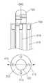
도 1에 도시되는 바와 같이 상기 스티어링 와이어(410)는 한 쌍으로 구성되며, 상기 가이드 니들(300)을 관통하도록 설치된다. 상기 한 쌍의 가이드 니들(300)은 서로 180도를 유지하도록 설치된다.As shown in FIG. 1, the
물론, 도 2에 도시되는 바와 같이, 스티어링 와이어(410)는 단일개로 구성될 수도 있다.Of course, as shown in FIG. 2, the
이에 더하여, 도면에 도시되지는 않았지만, 본 발명에 따르는 스티어링 와이어(410)는 다수의 쌍을 이룰 수 있다. 이러한 경우, 각 쌍은 서로 180도를 유지하도록 가이드 니들(300)에 설치되는 것이 좋다.In addition, although not shown in the drawings, the
상기 스티어링 와이어(410)의 일단은 튜브(200)의 일단에 연결된다. 상기 스티어링 와이어(410)의 타단은 상기 회전체(420)에 연결된다.One end of the
물론, 상기 스티어링 와이어(410)가 쌍으로 구성되는 경우에도, 상기와 동일하게 연결된다.Of course, even when the
한편, 상기 가이드 니들(300)에는 일정의 고정력을 형성시키면서 외력을 받으면 변형이 가능한 스티프닝 와이어(310)가 설치된다.On the other hand, the
상기 회전체(420)는 회전 핸들일 수 있다. 상기 회전 핸들은 손잡이 부의 일정 위치에 회전 가능하도록 설치된다.The rotating
상기 회전체(420)를 일방향 또는 타방향을 따라 돌림으로써, 각 스티어링 와이어(410)를 당기거나 풀 수 있으며, 이의 동작에 따라 튜브(200)는 반경 방향을 따라 이동될 수 있다.By rotating the rotating
상기에 언급되는 상기 스티어링 와이어(410)는 금속재질의 원형 와이어 또는 판 스프링 중 어느 하나일 수 있다.The
이에 더하여, 상기 회전체(420)가 회전 모터인 경우, 상기 회전 모터의 회전축은 각 스티어링 와이어(410)의 타단과 연결된다.In addition, when the rotating
상기 회전 모터는 외부로부터 전기적 신호를 받아 작동되고, 회전 모터의 작동에 따라 튜브(200)의 일단을 반경 방향을 따라 진동을 형성할 수도 있다.The rotary motor is operated by receiving an electrical signal from the outside, and may form vibrations along one end of the
상기 회전 모터는 후술되는 제어기(520)와 전기적으로 연결되며, 상기 제어기(520)에 설정되는 진동으로 작동될 수 있다.The rotary motor is electrically connected to a
그리고, 상기 진동 발생부(500)는, 진동 모터(510)와, 제어기(520)로 구성된다.In addition, the
도 5 및 도 6에 도시되는 바와 같이, 상기 진동 모터(510)는 손잡이 부(550)의 내부에 설치된다. 상기 진동 모터(510)는 상기 실린더(100)의 타단과 연결된다. 상기 진동 모터(510)는 제어기(520)로부터 전기적 신호를 전송 받아 상기 실린더(100)를 축방향을 따라 일정 진동으로 작동시킨다.5 and 6, the
또한, 상기 손잡이 부(550)에는, 상기 진동 모터(510)를 측방향을 따라 슬라이딩 이동 위치시킬 수 있는 이동 부재(530)가 더 구비될 수 있다.In addition, the
상기 이동 부재(530)는 스크류 방식일 수 있다. 상기 이동 부재(530)의 일단은 상기 진동 모터(510)에 연결되고, 타단은 상기 손잡이 부(550)의 외부로 돌출된다. 상기 이동 부재(530)는 손잡이 부(550)에 스크류 체결 관통될 수 있다.The moving
따라서, 상기 이동 부재(530)의 회전 동작에 따라, 상기 진동 모터(510)는 일측 또는 타측 방향을 따라 슬라이딩 이동될 수 있다.Therefore, the
상기에서 언급된 스크류 방식은 이동 부재(530)의 일 예이며, 이 예 이외에 선형으로 이동시키기 위한 기술 모두 채택될 수 있다.
The screw method mentioned above is an example of the moving
또 한편, 본 발명에 따르는 실린더(100)는 금속재질의 와이어 또는 광섬유 중 어느 하나로 형성될 수 있다.In addition, the
또한, 상기 광섬유는 플라스틱 광섬유인 것이 바람직하다.
In addition, the optical fiber is preferably a plastic optical fiber.
다음은, 도 3a 내지 도 3d를 참조로 하여, 본 발명의 진단용 프로브의 작용을 설명한다.Next, the operation of the diagnostic probe of the present invention will be described with reference to FIGS. 3A to 3D.
본 발명에 따르는 튜브(200)는 인체에 무해한 폴리머(biocompatible polymer) 계열의 물질로 형성될 수 있고, 튜브(200)를 반경방향으로 스티어링 할 경우에는 2개의 관을 사용하며, 이 스티어링을 더욱 정밀하게 구동하려면 4개의 관을 사용할 수도 있다.
[스티어링 동작][Steering behavior]
도면 3a 내지 도 3d를 참조 하면, 스티어링 와이어(410)에 90도로 배열된 2개의 스티프닝 와이어(310)는 튜브(200) 내로 삽입된다.3A to 3D, two stiffening
스티프닝 와이어(310)의 한쪽 끝은 튜브(200)의 끝부분에, 스티프닝 와이어(310)의 다른 한쪽 끝은 손잡이 부(550)의 일정 위치에 팽팽하게 고정된다.One end of the
따라서, 스티어링 와이어(410)를 이용하여 프로브를 반경 방향으로 구동할 때, 상기의 스티프닝 와이어(310)가 구동 방향의 90도 방향으로는 움직임을 억제하기 때문에 프로브 끝이 원하는 방향으로 정밀하게 휘어질 수 있다.Therefore, when the probe is driven in the radial direction using the
따라서 시술자가 프로브 끝을 원하는 부위에 위치시키는 정확성을 높일 수 있다.
Therefore, the operator can increase the accuracy of positioning the probe tip in the desired area.
[축방향 진동][Axial vibration]
도 3a와 도 3b를 참조 하면, 진동 모터(510)는 변형 가능한 실린더(100)에 연결된다. 진동 모터(510)의 주파수, 진폭을 조절함으로써 연결된 프로브의 끝단을 통해 디스크 조직에 전달되는 축방향 진동 자극의 빈도수 및 크기를 변경할 수 있다.3A and 3B, the
상기 변형 가능한 실린더(100)는 광섬유, 바람직하게는 플라스틱 광섬유를 사용한다.The
상기 실린더(100)는 금속재의 와이어를 사용할 수도 있다.The
또한, 이동 부재(530)를 사용하여 진동 모터(510)를 중심축으로터 멀어지게 이동하면, 프로브 끝단의 진동 크기가 작아지므로 디스크 조직에 전달되는 축방향 진동 자극의 크기를 더욱 정밀하게 변경할 수 있다.In addition, when the vibrating
상기 진동 모터(510)는 부분적인 왕복운동을 수행하는 회전형 전기모터로 대체할 수 있다.
The
[반경 방향 진동][Radial vibration]
스티어링 와이어(410)가 연결된 회전 핸들(420)을 전기모터로 대체할 경우, 프로브 끝단 반경방향 진동을 동시에 구현할 수 있다.When the
상기 회전 모터는 선형 또는 회전형 전기모터이며, 2개 또는 1개의 스티어링 와이어를 연결한다.The rotary motor is a linear or rotary electric motor and connects two or one steering wires.
도 4를 참조 하면, 프로브 끝단의 반경방향 진동은 디스크 내부 조직의 파괴가 다소 발생할 수 있으나, 축방향과는 다른 방향의 진동이므로 의료진단의 관점에서 다른 정보를 얻을 수 있다..
Referring to FIG. 4, the radial vibration of the probe tip may cause some destruction of the internal structure of the disc, but because of vibration in a direction different from that of the axial direction, other information may be obtained from the viewpoint of medical diagnosis.
다음은, 본 발명의 검사장치를 설명한다.Next, the inspection apparatus of this invention is demonstrated.
도 5를 참조 하면, 상기 검사 장치는 상기 실린더(100)의 단부에 설치되며, 디스크의 정상부위와 병변부위의 임피던스를 측정하는 전기 센서(600)와, 상기 실린더(100)를 통해 상기 측정되는 결과를 저장하는 저장부(700)로 구성된다.Referring to Figure 5, the inspection device is installed at the end of the
상기 실린더(100)는 금속재질의 와이어 또는 광섬유 중 어느 하나로 형성될 수 있상기 광섬유는 플라스틱 광섬유일 수 있다. The
도 3b, 도 3d의 전기적 센싱에서는, 변형 가능한 실린더(100) 끝 부분에 제안하는 전극(600)이 위치한다. 이 전극(600)을 이용하여 디스크의 정상부위와 병변부위의 임피던스 차이를 측정하여 진단의 정확성을 높일 수 있다.In the electrical sensing of FIGS. 3B and 3D, the
그리고, 상기 측정된 결과는 실린더(100)를 통하여 저장부(700)로 전송된다.In addition, the measured result is transmitted to the
도 7을 참조 하면, 제안하는 광학적 센싱은 광섬유, 바람직하게는 플라스틱 광섬유를 변형 가능한 실린더(100)로 사용함으로써 구현된다. 이때, 광섬유는 광전송을 위한 전송로로 사용된다.Referring to FIG. 7, the proposed optical sensing is implemented by using an optical fiber, preferably a plastic optical fiber, as the
따라서, 센싱 결과는 실시간으로 모니터링할 수 있으며, 필요시 검사정보를 저장할 수 있다.Therefore, the sensing result can be monitored in real time, and the inspection information can be stored when necessary.
여기서, 710은 레이저 소스이고, 720은 파워미터이며, 730은 디텍터이다.
Here, 710 is a laser source, 720 is a power meter, and 730 is a detector.
100 : 실린더200 : 실린더
300 : 가이드 니들400 : 방향 제어부
410 : 스티어링 와이어420 : 회전체
500 : 진동 발생부510 : 진동 모터
520 : 제어기530 : 이동 부재
550 : 손잡이 부600 : 전기 센서
700 : 저장부100: cylinder 200: cylinder
300: guide needle 400: direction control
410: steering wire 420: rotating body
500: vibration generating unit 510: vibration motor
520: controller 530: moving member
550: knob 600: electric sensor
700: storage
Claims (12)
Translated fromKorean양단이 외부에 노출되도록 상기 튜브에 끼워져 설치되는 변형 가능한 실린더;
중공 형상으로 형성되고, 상기 튜브의 외측 둘레를 감싸도록 배치되는 일정 길이의 가이드 니들;
상기 튜브의 단부와 연결되며, 외부로부터 동력을 전달 받아 상기 튜브를 반경 방향을 따라 위치시키거나 또는 진동시키는 방향 제어부;
외부로부터 동력을 전달 받아 상기 실린더를 축방향을 따라 진동시키는 진동 발생부; 및
상기 튜브의 단부와 연결되며, 상기 방향 제어부와 상기 진동 발생부와 연결되는 손잡이 부를 포함하는 것을 특징으로 하는 진단용 프로브.
Tubes of constant length;
A deformable cylinder fitted to the tube so that both ends thereof are exposed to the outside;
A guide needle having a hollow shape and disposed to surround the outer circumference of the tube;
A direction control unit connected to an end of the tube and receiving power from the outside to position or vibrate the tube along a radial direction;
Vibration generating unit for receiving the power from the outside to vibrate the cylinder in the axial direction; And
And a handle part connected to an end of the tube and connected to the direction control part and the vibration generating part.
상기 방향 제어부는,
상기 가이드 니들을 관통하며, 일단이 상기 튜브와 연결되는 일정 길이의 스티어링 와이어와,
상기 스티어링 와이어의 타단에 연결되며, 상기 스티어링 와이어를 당기도록 회전되는 회전체를 구비하는 것을 특징으로 하는 진단용 프로브.
The method of claim 1,
The direction control unit,
A steering wire having a predetermined length penetrating the guide needle and having one end connected to the tube;
And a rotary body connected to the other end of the steering wire and rotated to pull the steering wire.
상기 스티어링 와이어는,
다수의 쌍을 이루어 상기 가이드 니들을 관통하도록 설치되며,
상기 다수의 쌍을 이루는 스티어링 와이어는 서로 180도 간격을 이루어 설치되는 것을 특징으로 하는 진단용 프로브.
3. The method of claim 2,
The steering wire,
Installed in a plurality of pairs to penetrate the guide needle,
The plurality of pair of steering wire is diagnostic probe, characterized in that installed at intervals of 180 degrees from each other.
상기 회전체는,
상기 스티어링 와이어의 타단이 연결되어, 상기 스티어링 와이어를 당기도록 회전되는 회전 핸들인 것을 특징으로 하는 진단용 프로브.
3. The method of claim 2,
The rotating body includes:
The other end of the steering wire is connected, the diagnostic probe, characterized in that the rotating handle rotates to pull the steering wire.
상기 회전체는,
상기 스티어링 와이어의 타단과 연결되며, 외부로부터 동력을 전달 받아, 상기 튜브를 반경 방향을 따라 위치시키거나 또는 일정의 진동을 발생시키는 회전 모터인 것을 특징으로 하는 진단용 프로브.
3. The method of claim 2,
The rotating body includes:
And a rotary motor connected to the other end of the steering wire and receiving power from the outside to position the tube in a radial direction or to generate a predetermined vibration.
상기 진동 발생부는,
상기 실린더의 타단에 연결되며, 축방향을 따라 상기 실린더를 진동시키는 진동 모터와,
상기 진동 모터의 작동을 제어하며, 상기 진동에 요구되는 진동값이 가변 설정되는 것을 특징으로 하는 진단용 프로브.
The method of claim 1,
The vibration generating unit may include:
A vibration motor connected to the other end of the cylinder and vibrating the cylinder along an axial direction;
And controlling the operation of the vibration motor, wherein the vibration value required for the vibration is variably set.
상기 손잡이 부에는,
상기 진동 모터를 측방향을 따라 슬라이딩 이동 위치시킬 수 있는 이동 부재가 더 구비되는 것을 특징으로 하는 진단용 프로브.
The method according to claim 6,
In the handle part,
Diagnostic probes, characterized in that further provided with a movable member for sliding the vibration motor position in the lateral direction.
상기 가이드 니들에는,
일정의 고정력을 형성하는 적어도 하나 이상의 스티프닝 와이어가 설치되는 것을 특징으로 하는 진단용 프로브.
The method of claim 1,
The guide needle,
Diagnostic probe, characterized in that at least one or more stiffening wire is installed to form a fixed force.
상기 스티어링 와이어는 금속재질의 원형 와이어 또는 판 스프링 중 어느 하나인 것을 특징으로 하는 진단용 프로브.
3. The method of claim 2,
The steering wire is a diagnostic probe, characterized in that any one of a metal round wire or a leaf spring.
상기 실린더는 금속재질의 와이어 또는 광섬유 중 어느 하나로 형성되는 것을 특징으로 하는 진단용 프로브.
The method of claim 1,
The cylinder is a diagnostic probe, characterized in that formed of any one of a metal wire or optical fiber.
상기 광섬유는 플라스틱 광섬유인 것을 특징으로 하는 진단용 프로브.
The method of claim 10,
The optical fiber is a diagnostic probe, characterized in that the plastic optical fiber.
상기 실린더의 단부에 설치되며, 디스크의 정상부위와 병변부위의 임피던스를 측정하는 전기 센서 및 광신호를 측정하는 광학적 센서를 갖는 센서부; 및
상기 실린더를 통해 상기 전기 센서에 의해 측정되는 결과 및 상기 광학적 센서에 의해 측정되는 결과 중 적어도 하나의 결과를 저장하는 저장부를 포함하는 검사장치.A diagnostic probe according to any one of claims 1 to 11;
A sensor unit installed at an end of the cylinder, the sensor unit having an electrical sensor measuring an impedance of a top portion and a lesion portion of a disk and an optical sensor measuring an optical signal; And
And a storage unit for storing at least one result of the result measured by the electrical sensor and the result measured by the optical sensor through the cylinder.
Priority Applications (4)
| Application Number | Priority Date | Filing Date | Title |
|---|---|---|---|
| KR20120049956AKR101352799B1 (en) | 2012-05-10 | 2012-05-10 | Diagnostic probe and inspection apparatus having the same |
| JP2015511379AJP5956066B2 (en) | 2012-05-10 | 2013-05-10 | Diagnostic probe and inspection apparatus having the same |
| PCT/KR2013/004188WO2013169083A1 (en) | 2012-05-10 | 2013-05-10 | Diagnostic probe and inspection apparatus comprising same |
| US14/399,209US20150119723A1 (en) | 2012-05-10 | 2013-05-10 | Diagnostic probe and inspection apparatus comprising same |
Applications Claiming Priority (1)
| Application Number | Priority Date | Filing Date | Title |
|---|---|---|---|
| KR20120049956AKR101352799B1 (en) | 2012-05-10 | 2012-05-10 | Diagnostic probe and inspection apparatus having the same |
Publications (2)
| Publication Number | Publication Date |
|---|---|
| KR20130126124A KR20130126124A (en) | 2013-11-20 |
| KR101352799B1true KR101352799B1 (en) | 2014-02-17 |
Family
ID=49551021
Family Applications (1)
| Application Number | Title | Priority Date | Filing Date |
|---|---|---|---|
| KR20120049956AExpired - Fee RelatedKR101352799B1 (en) | 2012-05-10 | 2012-05-10 | Diagnostic probe and inspection apparatus having the same |
Country Status (4)
| Country | Link |
|---|---|
| US (1) | US20150119723A1 (en) |
| JP (1) | JP5956066B2 (en) |
| KR (1) | KR101352799B1 (en) |
| WO (1) | WO2013169083A1 (en) |
Cited By (1)
| Publication number | Priority date | Publication date | Assignee | Title |
|---|---|---|---|---|
| KR101860906B1 (en)* | 2017-03-14 | 2018-05-24 | (주)엠케어코리아 | The guide wire and the flexible catheter having that |
Families Citing this family (1)
| Publication number | Priority date | Publication date | Assignee | Title |
|---|---|---|---|---|
| KR102361305B1 (en) | 2020-03-03 | 2022-02-10 | (주)페블아이 | lateral flow rapid diagnostics testing apparatus with high sensitivity |
Citations (4)
| Publication number | Priority date | Publication date | Assignee | Title |
|---|---|---|---|---|
| JP2000325353A (en)* | 1999-05-18 | 2000-11-28 | Hisayoshi Suga | Vertebral body/intervertebral disk excision instrument |
| KR20040065157A (en)* | 2001-06-14 | 2004-07-21 | 인트린식 쎄라퓨틱스 인코포레이티드 | Intervertebral diagnostic and manipulation device |
| KR20080086836A (en)* | 2007-03-23 | 2008-09-26 | 올림푸스 메디칼 시스템즈 가부시키가이샤 | Medical instruments |
| KR20120058224A (en)* | 2010-11-29 | 2012-06-07 | 광주과학기술원 | Probe and Device for Inspecting Abnormality of an Intervertebral Disc |
Family Cites Families (19)
| Publication number | Priority date | Publication date | Assignee | Title |
|---|---|---|---|---|
| US5086775A (en)* | 1990-11-02 | 1992-02-11 | University Of Rochester | Method and apparatus for using Doppler modulation parameters for estimation of vibration amplitude |
| JP3242434B2 (en)* | 1992-01-14 | 2001-12-25 | オリンパス光学工業株式会社 | catheter |
| US5908395A (en)* | 1997-03-17 | 1999-06-01 | Advanced Cardiovascular Systems, Inc. | Vibrating guidewire |
| JPH10277163A (en)* | 1997-04-03 | 1998-10-20 | Olympus Optical Co Ltd | Hyperthermia applicator |
| JP4486743B2 (en)* | 2000-10-31 | 2010-06-23 | 株式会社町田製作所 | System for analyzing adhered substances on the inner wall of blood vessels |
| US6856712B2 (en)* | 2000-11-27 | 2005-02-15 | University Of Washington | Micro-fabricated optical waveguide for use in scanning fiber displays and scanned fiber image acquisition |
| US6638276B2 (en)* | 2001-06-06 | 2003-10-28 | Oratec Interventions, Inc. | Intervertebral disc device employing prebent sheath |
| US6638253B2 (en)* | 2001-07-17 | 2003-10-28 | Eugene Michael Breznock | Method and apparatus for chest drainage |
| CA2457376C (en)* | 2003-10-14 | 2015-09-15 | The University Of British Columbia | Method for imaging the mechanical properties of tissue |
| US7452351B2 (en)* | 2004-04-16 | 2008-11-18 | Kyphon Sarl | Spinal diagnostic methods and apparatus |
| US8761865B2 (en)* | 2005-03-10 | 2014-06-24 | Anatoly Babchenko | Optical sensor and a method of its use |
| US20070129732A1 (en)* | 2005-11-28 | 2007-06-07 | Jaime Zacharias | Spring-Mass Surgical System |
| US8394111B2 (en)* | 2006-01-13 | 2013-03-12 | Olympus Medical Systems Corp. | Endoscopic treatment instrument and retaining device |
| US20080027554A1 (en)* | 2006-07-31 | 2008-01-31 | Talmadge Karen D | Kit and methods of treatment of an intervertebral disc |
| US8323199B2 (en)* | 2007-09-28 | 2012-12-04 | The University Of British Columbia | Method and apparatus for imaging the mechanical properties of tissue from an endocavity |
| US8343096B2 (en)* | 2008-03-27 | 2013-01-01 | St. Jude Medical, Atrial Fibrillation Division, Inc. | Robotic catheter system |
| US9101735B2 (en)* | 2008-07-07 | 2015-08-11 | Intuitive Surgical Operations, Inc. | Catheter control systems |
| JP5394951B2 (en)* | 2010-02-28 | 2014-01-22 | 浩 石坂 | Puncture needle guide device |
| JP2013534841A (en)* | 2010-06-13 | 2013-09-09 | アンジオメトリックス コーポレーション | Diagnostic kit and method for measuring balloon dimensions in vivo |
- 2012
- 2012-05-10KRKR20120049956Apatent/KR101352799B1/ennot_activeExpired - Fee Related
- 2013
- 2013-05-10WOPCT/KR2013/004188patent/WO2013169083A1/enactiveApplication Filing
- 2013-05-10JPJP2015511379Apatent/JP5956066B2/ennot_activeExpired - Fee Related
- 2013-05-10USUS14/399,209patent/US20150119723A1/ennot_activeAbandoned
Patent Citations (4)
| Publication number | Priority date | Publication date | Assignee | Title |
|---|---|---|---|---|
| JP2000325353A (en)* | 1999-05-18 | 2000-11-28 | Hisayoshi Suga | Vertebral body/intervertebral disk excision instrument |
| KR20040065157A (en)* | 2001-06-14 | 2004-07-21 | 인트린식 쎄라퓨틱스 인코포레이티드 | Intervertebral diagnostic and manipulation device |
| KR20080086836A (en)* | 2007-03-23 | 2008-09-26 | 올림푸스 메디칼 시스템즈 가부시키가이샤 | Medical instruments |
| KR20120058224A (en)* | 2010-11-29 | 2012-06-07 | 광주과학기술원 | Probe and Device for Inspecting Abnormality of an Intervertebral Disc |
Cited By (1)
| Publication number | Priority date | Publication date | Assignee | Title |
|---|---|---|---|---|
| KR101860906B1 (en)* | 2017-03-14 | 2018-05-24 | (주)엠케어코리아 | The guide wire and the flexible catheter having that |
Also Published As
| Publication number | Publication date |
|---|---|
| WO2013169083A1 (en) | 2013-11-14 |
| JP2015520633A (en) | 2015-07-23 |
| US20150119723A1 (en) | 2015-04-30 |
| KR20130126124A (en) | 2013-11-20 |
| JP5956066B2 (en) | 2016-07-20 |
Similar Documents
| Publication | Publication Date | Title |
|---|---|---|
| JP7134999B2 (en) | Device and method for measuring viscoelastic properties of viscoelastic media | |
| US9125677B2 (en) | Diagnostic and feedback control system for efficacy and safety of laser application for tissue reshaping and regeneration | |
| CN107438393B (en) | Magnetic resonance MR compatible transducer for magnetic resonance elastography | |
| KR102759452B1 (en) | Hybrid elastography method, probe and device for hybrid elastography | |
| EP2932930A1 (en) | Treatment instrument | |
| JP4359626B2 (en) | Loading device | |
| JP2010536472A (en) | Method and apparatus for measuring mechanical properties of tissue | |
| KR20200030838A (en) | High intensity focused ultrasound device and control method of piezo-electric driving device used to the same | |
| US20170252006A1 (en) | Ultrasonic measurement apparatus and ultrasonic probe | |
| KR101219710B1 (en) | Probe and Device for Inspecting Abnormality of an Intervertebral Disc | |
| KR101352799B1 (en) | Diagnostic probe and inspection apparatus having the same | |
| US9138286B2 (en) | Ultrasound detectable interventional medical device | |
| JP2017500127A (en) | Invasive medical needle and needle assembly | |
| US10602985B2 (en) | Contact detection instrument | |
| He et al. | Dual-stiffness force-sensing cannulation tool for retinal microsurgery | |
| KR20200128085A (en) | Method for measuring ultrasonic attenuation parameters guided by harmonic elastography, probes and apparatus for implementation of this method | |
| JP2007202799A (en) | Ultrasonic diagnostic system and load device | |
| US10085718B2 (en) | Ultrasonic probe with a beam having an ultrasonic transducer | |
| JP2014176429A (en) | Trans-body cavity cauterization device | |
| KR101018409B1 (en) | 3D property diagnosis device and method | |
| WO2024156446A2 (en) | Torsional ultrasonic waves transducer medical device thereof | |
| KR101018408B1 (en) | Physical Diagnosis Device and Method | |
| RU68894U1 (en) | DEVICE FOR ASSESSING THE PARAMETERS OF BIOLOGICALLY ACTIVE POINTS | |
| JPH1199129A (en) | Insertion piece navigator | |
| JP2007007343A (en) | Ultrasonic diagnostic equipment |
Legal Events
| Date | Code | Title | Description |
|---|---|---|---|
| PA0109 | Patent application | St.27 status event code:A-0-1-A10-A12-nap-PA0109 | |
| A201 | Request for examination | ||
| PA0201 | Request for examination | St.27 status event code:A-1-2-D10-D11-exm-PA0201 | |
| D13-X000 | Search requested | St.27 status event code:A-1-2-D10-D13-srh-X000 | |
| D14-X000 | Search report completed | St.27 status event code:A-1-2-D10-D14-srh-X000 | |
| E902 | Notification of reason for refusal | ||
| PE0902 | Notice of grounds for rejection | St.27 status event code:A-1-2-D10-D21-exm-PE0902 | |
| P11-X000 | Amendment of application requested | St.27 status event code:A-2-2-P10-P11-nap-X000 | |
| P13-X000 | Application amended | St.27 status event code:A-2-2-P10-P13-nap-X000 | |
| PG1501 | Laying open of application | St.27 status event code:A-1-1-Q10-Q12-nap-PG1501 | |
| E701 | Decision to grant or registration of patent right | ||
| PE0701 | Decision of registration | St.27 status event code:A-1-2-D10-D22-exm-PE0701 | |
| GRNT | Written decision to grant | ||
| PR0701 | Registration of establishment | St.27 status event code:A-2-4-F10-F11-exm-PR0701 | |
| PR1002 | Payment of registration fee | St.27 status event code:A-2-2-U10-U11-oth-PR1002 Fee payment year number:1 | |
| PG1601 | Publication of registration | St.27 status event code:A-4-4-Q10-Q13-nap-PG1601 | |
| FPAY | Annual fee payment | Payment date:20161219 Year of fee payment:4 | |
| PR1001 | Payment of annual fee | St.27 status event code:A-4-4-U10-U11-oth-PR1001 Fee payment year number:4 | |
| PR1001 | Payment of annual fee | St.27 status event code:A-4-4-U10-U11-oth-PR1001 Fee payment year number:5 | |
| LAPS | Lapse due to unpaid annual fee | ||
| PC1903 | Unpaid annual fee | St.27 status event code:A-4-4-U10-U13-oth-PC1903 Not in force date:20190114 Payment event data comment text:Termination Category : DEFAULT_OF_REGISTRATION_FEE | |
| P22-X000 | Classification modified | St.27 status event code:A-4-4-P10-P22-nap-X000 | |
| P22-X000 | Classification modified | St.27 status event code:A-4-4-P10-P22-nap-X000 | |
| PC1903 | Unpaid annual fee | St.27 status event code:N-4-6-H10-H13-oth-PC1903 Ip right cessation event data comment text:Termination Category : DEFAULT_OF_REGISTRATION_FEE Not in force date:20190114 | |
| R18-X000 | Changes to party contact information recorded | St.27 status event code:A-5-5-R10-R18-oth-X000 | |
| R18-X000 | Changes to party contact information recorded | St.27 status event code:A-5-5-R10-R18-oth-X000 |