KR101352546B1 - Intervertebral Disc Prostheses - Google Patents
Intervertebral Disc ProsthesesDownload PDFInfo
- Publication number
- KR101352546B1 KR101352546B1KR1020087024503AKR20087024503AKR101352546B1KR 101352546 B1KR101352546 B1KR 101352546B1KR 1020087024503 AKR1020087024503 AKR 1020087024503AKR 20087024503 AKR20087024503 AKR 20087024503AKR 101352546 B1KR101352546 B1KR 101352546B1
- Authority
- KR
- South Korea
- Prior art keywords
- plato
- prosthesis
- intervertebral disc
- convex dome
- facing
- Prior art date
- Legal status (The legal status is an assumption and is not a legal conclusion. Google has not performed a legal analysis and makes no representation as to the accuracy of the status listed.)
- Active
Links
- 239000004696Poly ether ether ketoneSubstances0.000claimsdescription11
- 238000000034methodMethods0.000claimsdescription11
- 229920002530polyetherether ketonePolymers0.000claimsdescription11
- 238000000576coating methodMethods0.000claimsdescription5
- 239000011248coating agentSubstances0.000claimsdescription4
- 230000000295complement effectEffects0.000abstractdescription2
- 239000000463materialSubstances0.000description14
- RTAQQCXQSZGOHL-UHFFFAOYSA-NTitaniumChemical compound[Ti]RTAQQCXQSZGOHL-UHFFFAOYSA-N0.000description8
- 239000010936titaniumSubstances0.000description8
- 230000035939shockEffects0.000description7
- 229910001200FerrotitaniumInorganic materials0.000description6
- IUWCPXJTIPQGTE-UHFFFAOYSA-Nchromium cobaltChemical compound[Cr].[Co].[Co].[Co]IUWCPXJTIPQGTE-UHFFFAOYSA-N0.000description6
- 239000010935stainless steelSubstances0.000description6
- 229910001220stainless steelInorganic materials0.000description6
- 230000000694effectsEffects0.000description4
- 238000004381surface treatmentMethods0.000description4
- 230000032683agingEffects0.000description3
- 201000010099diseaseDiseases0.000description3
- 208000037265diseases, disorders, signs and symptomsDiseases0.000description3
- 208000014674injuryDiseases0.000description3
- 230000008733traumaEffects0.000description3
- 238000010521absorption reactionMethods0.000description2
- 238000005452bendingMethods0.000description2
- 230000007850degenerationEffects0.000description2
- 230000003412degenerative effectEffects0.000description2
- 230000003203everyday effectEffects0.000description2
- 229920005992thermoplastic resinPolymers0.000description2
- 229910052719titaniumInorganic materials0.000description2
- 208000010392Bone FracturesDiseases0.000description1
- OKTJSMMVPCPJKN-UHFFFAOYSA-NCarbonChemical compound[C]OKTJSMMVPCPJKN-UHFFFAOYSA-N0.000description1
- 229920000049Carbon (fiber)Polymers0.000description1
- 206010017076FractureDiseases0.000description1
- 239000004705High-molecular-weight polyethyleneSubstances0.000description1
- 229910052799carbonInorganic materials0.000description1
- 239000004917carbon fiberSubstances0.000description1
- 230000008602contractionEffects0.000description1
- 238000012937correctionMethods0.000description1
- 238000005336crackingMethods0.000description1
- 230000002354daily effectEffects0.000description1
- 230000007423decreaseEffects0.000description1
- 239000003365glass fiberSubstances0.000description1
- 229920001903high density polyethylenePolymers0.000description1
- 239000004700high-density polyethyleneSubstances0.000description1
- 238000003780insertionMethods0.000description1
- 230000037431insertionEffects0.000description1
- 230000009191jumpingEffects0.000description1
- VNWKTOKETHGBQD-UHFFFAOYSA-NmethaneChemical compoundCVNWKTOKETHGBQD-UHFFFAOYSA-N0.000description1
- 210000005036nerveAnatomy0.000description1
- 239000004033plasticSubstances0.000description1
- 229920003023plasticPolymers0.000description1
- WQGWDDDVZFFDIG-UHFFFAOYSA-NpyrogallolChemical compoundOC1=CC=CC(O)=C1OWQGWDDDVZFFDIG-UHFFFAOYSA-N0.000description1
- -1sold by BioProfileChemical compound0.000description1
- 230000003746surface roughnessEffects0.000description1
Images


Classifications
- A—HUMAN NECESSITIES
- A61—MEDICAL OR VETERINARY SCIENCE; HYGIENE
- A61F—FILTERS IMPLANTABLE INTO BLOOD VESSELS; PROSTHESES; DEVICES PROVIDING PATENCY TO, OR PREVENTING COLLAPSING OF, TUBULAR STRUCTURES OF THE BODY, e.g. STENTS; ORTHOPAEDIC, NURSING OR CONTRACEPTIVE DEVICES; FOMENTATION; TREATMENT OR PROTECTION OF EYES OR EARS; BANDAGES, DRESSINGS OR ABSORBENT PADS; FIRST-AID KITS
- A61F2/00—Filters implantable into blood vessels; Prostheses, i.e. artificial substitutes or replacements for parts of the body; Appliances for connecting them with the body; Devices providing patency to, or preventing collapsing of, tubular structures of the body, e.g. stents
- A61F2/02—Prostheses implantable into the body
- A61F2/30—Joints
- A61F2/44—Joints for the spine, e.g. vertebrae, spinal discs
- A61F2/442—Intervertebral or spinal discs, e.g. resilient
- A61F2/4425—Intervertebral or spinal discs, e.g. resilient made of articulated components
- A—HUMAN NECESSITIES
- A61—MEDICAL OR VETERINARY SCIENCE; HYGIENE
- A61F—FILTERS IMPLANTABLE INTO BLOOD VESSELS; PROSTHESES; DEVICES PROVIDING PATENCY TO, OR PREVENTING COLLAPSING OF, TUBULAR STRUCTURES OF THE BODY, e.g. STENTS; ORTHOPAEDIC, NURSING OR CONTRACEPTIVE DEVICES; FOMENTATION; TREATMENT OR PROTECTION OF EYES OR EARS; BANDAGES, DRESSINGS OR ABSORBENT PADS; FIRST-AID KITS
- A61F2/00—Filters implantable into blood vessels; Prostheses, i.e. artificial substitutes or replacements for parts of the body; Appliances for connecting them with the body; Devices providing patency to, or preventing collapsing of, tubular structures of the body, e.g. stents
- A61F2/02—Prostheses implantable into the body
- A61F2/30—Joints
- A61F2/44—Joints for the spine, e.g. vertebrae, spinal discs
- A—HUMAN NECESSITIES
- A61—MEDICAL OR VETERINARY SCIENCE; HYGIENE
- A61F—FILTERS IMPLANTABLE INTO BLOOD VESSELS; PROSTHESES; DEVICES PROVIDING PATENCY TO, OR PREVENTING COLLAPSING OF, TUBULAR STRUCTURES OF THE BODY, e.g. STENTS; ORTHOPAEDIC, NURSING OR CONTRACEPTIVE DEVICES; FOMENTATION; TREATMENT OR PROTECTION OF EYES OR EARS; BANDAGES, DRESSINGS OR ABSORBENT PADS; FIRST-AID KITS
- A61F2/00—Filters implantable into blood vessels; Prostheses, i.e. artificial substitutes or replacements for parts of the body; Appliances for connecting them with the body; Devices providing patency to, or preventing collapsing of, tubular structures of the body, e.g. stents
- A61F2/02—Prostheses implantable into the body
- A61F2/30—Joints
- A61F2/3094—Designing or manufacturing processes
- A61F2/30965—Reinforcing the prosthesis by embedding particles or fibres during moulding or dipping
- A—HUMAN NECESSITIES
- A61—MEDICAL OR VETERINARY SCIENCE; HYGIENE
- A61F—FILTERS IMPLANTABLE INTO BLOOD VESSELS; PROSTHESES; DEVICES PROVIDING PATENCY TO, OR PREVENTING COLLAPSING OF, TUBULAR STRUCTURES OF THE BODY, e.g. STENTS; ORTHOPAEDIC, NURSING OR CONTRACEPTIVE DEVICES; FOMENTATION; TREATMENT OR PROTECTION OF EYES OR EARS; BANDAGES, DRESSINGS OR ABSORBENT PADS; FIRST-AID KITS
- A61F2/00—Filters implantable into blood vessels; Prostheses, i.e. artificial substitutes or replacements for parts of the body; Appliances for connecting them with the body; Devices providing patency to, or preventing collapsing of, tubular structures of the body, e.g. stents
- A61F2/02—Prostheses implantable into the body
- A61F2/30—Joints
- A61F2002/30001—Additional features of subject-matter classified in A61F2/28, A61F2/30 and subgroups thereof
- A61F2002/30316—The prosthesis having different structural features at different locations within the same prosthesis; Connections between prosthetic parts; Special structural features of bone or joint prostheses not otherwise provided for
- A61F2002/30535—Special structural features of bone or joint prostheses not otherwise provided for
- A61F2002/30563—Special structural features of bone or joint prostheses not otherwise provided for having elastic means or damping means, different from springs, e.g. including an elastomeric core or shock absorbers
- A—HUMAN NECESSITIES
- A61—MEDICAL OR VETERINARY SCIENCE; HYGIENE
- A61F—FILTERS IMPLANTABLE INTO BLOOD VESSELS; PROSTHESES; DEVICES PROVIDING PATENCY TO, OR PREVENTING COLLAPSING OF, TUBULAR STRUCTURES OF THE BODY, e.g. STENTS; ORTHOPAEDIC, NURSING OR CONTRACEPTIVE DEVICES; FOMENTATION; TREATMENT OR PROTECTION OF EYES OR EARS; BANDAGES, DRESSINGS OR ABSORBENT PADS; FIRST-AID KITS
- A61F2/00—Filters implantable into blood vessels; Prostheses, i.e. artificial substitutes or replacements for parts of the body; Appliances for connecting them with the body; Devices providing patency to, or preventing collapsing of, tubular structures of the body, e.g. stents
- A61F2/02—Prostheses implantable into the body
- A61F2/30—Joints
- A61F2002/30001—Additional features of subject-matter classified in A61F2/28, A61F2/30 and subgroups thereof
- A61F2002/30621—Features concerning the anatomical functioning or articulation of the prosthetic joint
- A61F2002/30649—Ball-and-socket joints
- A—HUMAN NECESSITIES
- A61—MEDICAL OR VETERINARY SCIENCE; HYGIENE
- A61F—FILTERS IMPLANTABLE INTO BLOOD VESSELS; PROSTHESES; DEVICES PROVIDING PATENCY TO, OR PREVENTING COLLAPSING OF, TUBULAR STRUCTURES OF THE BODY, e.g. STENTS; ORTHOPAEDIC, NURSING OR CONTRACEPTIVE DEVICES; FOMENTATION; TREATMENT OR PROTECTION OF EYES OR EARS; BANDAGES, DRESSINGS OR ABSORBENT PADS; FIRST-AID KITS
- A61F2/00—Filters implantable into blood vessels; Prostheses, i.e. artificial substitutes or replacements for parts of the body; Appliances for connecting them with the body; Devices providing patency to, or preventing collapsing of, tubular structures of the body, e.g. stents
- A61F2/02—Prostheses implantable into the body
- A61F2/30—Joints
- A61F2002/30001—Additional features of subject-matter classified in A61F2/28, A61F2/30 and subgroups thereof
- A61F2002/30667—Features concerning an interaction with the environment or a particular use of the prosthesis
- A61F2002/30682—Means for preventing migration of particles released by the joint, e.g. wear debris or cement particles
- A61F2002/30685—Means for reducing or preventing the generation of wear particulates
- A—HUMAN NECESSITIES
- A61—MEDICAL OR VETERINARY SCIENCE; HYGIENE
- A61F—FILTERS IMPLANTABLE INTO BLOOD VESSELS; PROSTHESES; DEVICES PROVIDING PATENCY TO, OR PREVENTING COLLAPSING OF, TUBULAR STRUCTURES OF THE BODY, e.g. STENTS; ORTHOPAEDIC, NURSING OR CONTRACEPTIVE DEVICES; FOMENTATION; TREATMENT OR PROTECTION OF EYES OR EARS; BANDAGES, DRESSINGS OR ABSORBENT PADS; FIRST-AID KITS
- A61F2/00—Filters implantable into blood vessels; Prostheses, i.e. artificial substitutes or replacements for parts of the body; Appliances for connecting them with the body; Devices providing patency to, or preventing collapsing of, tubular structures of the body, e.g. stents
- A61F2/02—Prostheses implantable into the body
- A61F2/30—Joints
- A61F2/30721—Accessories
- A61F2002/30733—Inserts placed into an endoprosthetic cavity, e.g. for modifying a material property
- A—HUMAN NECESSITIES
- A61—MEDICAL OR VETERINARY SCIENCE; HYGIENE
- A61F—FILTERS IMPLANTABLE INTO BLOOD VESSELS; PROSTHESES; DEVICES PROVIDING PATENCY TO, OR PREVENTING COLLAPSING OF, TUBULAR STRUCTURES OF THE BODY, e.g. STENTS; ORTHOPAEDIC, NURSING OR CONTRACEPTIVE DEVICES; FOMENTATION; TREATMENT OR PROTECTION OF EYES OR EARS; BANDAGES, DRESSINGS OR ABSORBENT PADS; FIRST-AID KITS
- A61F2/00—Filters implantable into blood vessels; Prostheses, i.e. artificial substitutes or replacements for parts of the body; Appliances for connecting them with the body; Devices providing patency to, or preventing collapsing of, tubular structures of the body, e.g. stents
- A61F2/02—Prostheses implantable into the body
- A61F2/30—Joints
- A61F2/30767—Special external or bone-contacting surface, e.g. coating for improving bone ingrowth
- A61F2/30771—Special external or bone-contacting surface, e.g. coating for improving bone ingrowth applied in original prostheses, e.g. holes or grooves
- A61F2002/30841—Sharp anchoring protrusions for impaction into the bone, e.g. sharp pins, spikes
- A—HUMAN NECESSITIES
- A61—MEDICAL OR VETERINARY SCIENCE; HYGIENE
- A61F—FILTERS IMPLANTABLE INTO BLOOD VESSELS; PROSTHESES; DEVICES PROVIDING PATENCY TO, OR PREVENTING COLLAPSING OF, TUBULAR STRUCTURES OF THE BODY, e.g. STENTS; ORTHOPAEDIC, NURSING OR CONTRACEPTIVE DEVICES; FOMENTATION; TREATMENT OR PROTECTION OF EYES OR EARS; BANDAGES, DRESSINGS OR ABSORBENT PADS; FIRST-AID KITS
- A61F2/00—Filters implantable into blood vessels; Prostheses, i.e. artificial substitutes or replacements for parts of the body; Appliances for connecting them with the body; Devices providing patency to, or preventing collapsing of, tubular structures of the body, e.g. stents
- A61F2/02—Prostheses implantable into the body
- A61F2/30—Joints
- A61F2/30767—Special external or bone-contacting surface, e.g. coating for improving bone ingrowth
- A61F2002/30922—Hardened surfaces
- A—HUMAN NECESSITIES
- A61—MEDICAL OR VETERINARY SCIENCE; HYGIENE
- A61F—FILTERS IMPLANTABLE INTO BLOOD VESSELS; PROSTHESES; DEVICES PROVIDING PATENCY TO, OR PREVENTING COLLAPSING OF, TUBULAR STRUCTURES OF THE BODY, e.g. STENTS; ORTHOPAEDIC, NURSING OR CONTRACEPTIVE DEVICES; FOMENTATION; TREATMENT OR PROTECTION OF EYES OR EARS; BANDAGES, DRESSINGS OR ABSORBENT PADS; FIRST-AID KITS
- A61F2/00—Filters implantable into blood vessels; Prostheses, i.e. artificial substitutes or replacements for parts of the body; Appliances for connecting them with the body; Devices providing patency to, or preventing collapsing of, tubular structures of the body, e.g. stents
- A61F2/02—Prostheses implantable into the body
- A61F2/30—Joints
- A61F2/44—Joints for the spine, e.g. vertebrae, spinal discs
- A61F2/442—Intervertebral or spinal discs, e.g. resilient
- A61F2/4425—Intervertebral or spinal discs, e.g. resilient made of articulated components
- A61F2002/443—Intervertebral or spinal discs, e.g. resilient made of articulated components having two transversal endplates and at least one intermediate component
- A—HUMAN NECESSITIES
- A61—MEDICAL OR VETERINARY SCIENCE; HYGIENE
- A61F—FILTERS IMPLANTABLE INTO BLOOD VESSELS; PROSTHESES; DEVICES PROVIDING PATENCY TO, OR PREVENTING COLLAPSING OF, TUBULAR STRUCTURES OF THE BODY, e.g. STENTS; ORTHOPAEDIC, NURSING OR CONTRACEPTIVE DEVICES; FOMENTATION; TREATMENT OR PROTECTION OF EYES OR EARS; BANDAGES, DRESSINGS OR ABSORBENT PADS; FIRST-AID KITS
- A61F2310/00—Prostheses classified in A61F2/28 or A61F2/30 - A61F2/44 being constructed from or coated with a particular material
- A61F2310/00005—The prosthesis being constructed from a particular material
- A61F2310/00011—Metals or alloys
- A61F2310/00017—Iron- or Fe-based alloys, e.g. stainless steel
- A—HUMAN NECESSITIES
- A61—MEDICAL OR VETERINARY SCIENCE; HYGIENE
- A61F—FILTERS IMPLANTABLE INTO BLOOD VESSELS; PROSTHESES; DEVICES PROVIDING PATENCY TO, OR PREVENTING COLLAPSING OF, TUBULAR STRUCTURES OF THE BODY, e.g. STENTS; ORTHOPAEDIC, NURSING OR CONTRACEPTIVE DEVICES; FOMENTATION; TREATMENT OR PROTECTION OF EYES OR EARS; BANDAGES, DRESSINGS OR ABSORBENT PADS; FIRST-AID KITS
- A61F2310/00—Prostheses classified in A61F2/28 or A61F2/30 - A61F2/44 being constructed from or coated with a particular material
- A61F2310/00005—The prosthesis being constructed from a particular material
- A61F2310/00011—Metals or alloys
- A61F2310/00023—Titanium or titanium-based alloys, e.g. Ti-Ni alloys
- A—HUMAN NECESSITIES
- A61—MEDICAL OR VETERINARY SCIENCE; HYGIENE
- A61F—FILTERS IMPLANTABLE INTO BLOOD VESSELS; PROSTHESES; DEVICES PROVIDING PATENCY TO, OR PREVENTING COLLAPSING OF, TUBULAR STRUCTURES OF THE BODY, e.g. STENTS; ORTHOPAEDIC, NURSING OR CONTRACEPTIVE DEVICES; FOMENTATION; TREATMENT OR PROTECTION OF EYES OR EARS; BANDAGES, DRESSINGS OR ABSORBENT PADS; FIRST-AID KITS
- A61F2310/00—Prostheses classified in A61F2/28 or A61F2/30 - A61F2/44 being constructed from or coated with a particular material
- A61F2310/00005—The prosthesis being constructed from a particular material
- A61F2310/00011—Metals or alloys
- A61F2310/00029—Cobalt-based alloys, e.g. Co-Cr alloys or Vitallium
- A—HUMAN NECESSITIES
- A61—MEDICAL OR VETERINARY SCIENCE; HYGIENE
- A61F—FILTERS IMPLANTABLE INTO BLOOD VESSELS; PROSTHESES; DEVICES PROVIDING PATENCY TO, OR PREVENTING COLLAPSING OF, TUBULAR STRUCTURES OF THE BODY, e.g. STENTS; ORTHOPAEDIC, NURSING OR CONTRACEPTIVE DEVICES; FOMENTATION; TREATMENT OR PROTECTION OF EYES OR EARS; BANDAGES, DRESSINGS OR ABSORBENT PADS; FIRST-AID KITS
- A61F2310/00—Prostheses classified in A61F2/28 or A61F2/30 - A61F2/44 being constructed from or coated with a particular material
- A61F2310/00389—The prosthesis being coated or covered with a particular material
- A61F2310/00592—Coating or prosthesis-covering structure made of ceramics or of ceramic-like compounds
- A61F2310/00796—Coating or prosthesis-covering structure made of a phosphorus-containing compound, e.g. hydroxy(l)apatite
Landscapes
- Health & Medical Sciences (AREA)
- Engineering & Computer Science (AREA)
- Biomedical Technology (AREA)
- Orthopedic Medicine & Surgery (AREA)
- Neurology (AREA)
- Heart & Thoracic Surgery (AREA)
- Oral & Maxillofacial Surgery (AREA)
- Transplantation (AREA)
- Cardiology (AREA)
- Vascular Medicine (AREA)
- Life Sciences & Earth Sciences (AREA)
- Animal Behavior & Ethology (AREA)
- General Health & Medical Sciences (AREA)
- Public Health (AREA)
- Veterinary Medicine (AREA)
- Prostheses (AREA)
Abstract
Translated fromKoreanDescription
Translated fromKorean본 발명은 추간판 보철물에 대한 것이다.The present invention relates to an intervertebral disc prosthesis.
외상(trauma), 질병, 노화에 따른 퇴행 과정은 종종 추간판의 교체를 초래한다.Degeneration of trauma, disease, and aging often results in replacement of the intervertebral discs.
이러한 퇴행 과정은 두 개의 척추 사이의 자연적인 공간에 변화를 가져올 수 있다. 이 자연적인 공간이 수축되면 특정 신경에 작용하는 압력을 일으키고, 그 결과로서 통증이 발생할 수 있다.This degeneration process can change the natural space between the two vertebrae. Contraction of this natural space creates pressure on specific nerves, which can result in pain.
두 개의 척추 사이의 자연적인 공간을 유지하기 위하여 디스크 보철물이 사용될 수 있다. 그것은 척추가 이하에서 설명하는 자연적인 운동에 따라 서로에 대하여 이동할 수 있도록 해야 한다. 특히, 그것은 경부(cervical region)에서 인체의 몸통 또는 목의 회전 운동에 부분적으로 상응하는 축방향(axial) 회전운동, 경부에서 몸통 또는 머리의 상부를 굽히거나 늘이는 운동에 상응하는 전후방향(anteroposterior) 운동, 및 경부에서 몸통 또는 목 상부의 틸팅(tilting)에 상응하는 측방향(lateral) 운동을 허용해야 한다.Disc prostheses may be used to maintain the natural spacing between two vertebrae. It should allow the spine to move relative to each other according to the natural movements described below. In particular, it is an anteroposterior corresponding to an axial rotational movement, partly corresponding to the rotational movement of the torso or neck of the human body in the cervical region, and to the bending or stretching of the upper part of the torso or head in the cervical region. Exercise and lateral movement corresponding to tilting of the torso or neck at the neck should be allowed.
플라토(plateau)가 대개 가지고 있는 표면 처리 및 표면 거칠기의 결과로서, 디스크 보철물의 상부 및 하부 플라토가 척추를 지지하고 시간이 흐름에 따라 척추에 고정된다.As a result of the surface treatment and surface roughness that plato usually has, the upper and lower plato of the disk prosthesis support the spine and are fixed to the spine over time.
유럽특허 출원 EP-A1-1 344 508은 상부 플라토, 지지면을 가지는 하부 플라토, 구형 부분(spherical part)을 가지는 상부면 및 하부면을 포함하는 중간부를 포함하는 추간판 보철물을 나타내는데, 상부 플라토는 구형 부분을 보완하는 임프레션(impression)을 가져 구형 부분과 접촉하게 됨으로써 상부 플라토와 중간부 사이에서 볼-소켓 조인트(ball-socket joint)를 한정하게 되고, 중간부의 하부면은 지지면과 접촉하게 된다.European patent application EP-A1-1 344 508 shows an intervertebral disc prosthesis comprising an intermediate portion comprising an upper plato, a lower plato with a support surface, an upper surface with a spherical part and a lower surface, wherein the upper plato is spherical. Contact with the spherical portion has an impression that complements the portion, thereby defining a ball-socket joint between the upper plato and the middle portion, and the lower surface of the middle portion is in contact with the support surface.
중간부는 하부 플라토의 지지면 상에서 전방 및 후방으로 이동할 수 있다.The intermediate part can move forward and backward on the support surface of the lower plato.
그러나, 이러한 타입의 보철물은, 특히 격한 충격을 받는 동안, 원하는 안락함과 강고함을 제공하지는 아니한다.However, this type of prosthesis does not provide the desired comfort and rigidity, especially during severe shocks.
국제특허출원 WO 2004/016247은 추간판 보철물을 제시하고 있다. 다양한 범위의 구성들이 제안되고 있다. 이들 중 하나에서, 하부 플라토, 상부 플라토 및 상부 플라토에 형성된 공동(cavity)과 함께 작용하는 상부 볼록면을 포함하는 중간부가 제시되고 있다. 중간부는 길고 좁은 수평 노치(notch)를 포함한다.International patent application WO 2004/016247 proposes an intervertebral disc prosthesis. Various ranges of configurations have been proposed. In one of these, an intermediate portion is shown which comprises a lower plato, an upper plato and an upper convex surface which acts with a cavity formed in the upper plato. The middle part contains a long narrow horizontal notch.
그러나, 적절히 충격 흡수를 하기 위하여, 이러한 타입의 보철물은 피로 파열 균열(crack)을 일으키는 매우 깊은 노치를 필요로 하는데, 이는 보철물을 상당히 약화시키고 특히 격한 충격이나 회전을 받는 동안 원하는 강고함을 얻을 수 없게 한다.However, in order to properly absorb shock, this type of prosthesis requires a very deep notch that causes fatigue rupture cracking, which significantly weakens the prosthesis and does not achieve the desired rigidity, especially during severe impacts or turns. do.
본 발명의 목적은 특히 세 가지 단점을 극복하는 것이다.The object of the invention is in particular to overcome three disadvantages.
이 때문에, 본 발명의 주제는 다음의 것들을 포함하여 이루어지는 추간판 보철물이 된다.For this reason, the subject of this invention is an intervertebral disc prosthesis which consists of the following things.
- 상부 척추를 지지하는 외부면 및 보철물의 내부를 향하는 면을 가지는 상부 플라토An upper plato having an outer surface for supporting the upper vertebrae and an inner facing surface of the prosthesis
- 하부 척추를 지지하는 외부면 및 보철물의 내부를 향하는 면을 가지는 하부 플라토A lower plato having an outer surface supporting the lower vertebrae and an inner facing surface of the prosthesis
- 바람직하게는 구형인, 볼록 돔부(convex domed part)를 포함하고, 볼록 돔부를 보완하는 임프레션과 함께 작용하며, 볼록 돔부와 접촉하는, 상부 플라토와 하부 플라토 사이의 볼-소켓 조인트로서, 상기 볼록 돔부는 일상 생활에서 갑작스럽거나 진동이 있는 움직임이 있는 동안 특히 수직 충격의 경우 볼록 돔부가 변형할 수 있게끔 하는 적어도 하나의 루멘(lumen)을 포함하는 것인 볼-소켓 조인트.A ball-socket joint between the upper plato and the lower plato, comprising a convex domed part, preferably spherical, which acts in conjunction with an impression that complements the convex domed part and which contacts the convex dome part; The ball-socket joint, wherein the dome portion comprises at least one lumen that allows the convex dome portion to deform during a sudden or vibrating movement in everyday life, especially in the case of vertical impact.
일상 생활(충돌, 점프, 사고, 낙하, 격한 움직임, 위험한 스포츠(스키, 승마 등))에서 갑작스럽거나 진동이 있는 움직임이 있는 동안 돔부가 변형되는 것은, 그 핵심이 상기 볼록 돔부의 평탄화, 즉 높이 감소에 있다. 바람직하게는, 걷기와 같은 일상 생활 통상의 움직임이 있는 동안에는 돔부에 어떠한 변형도 일어나지 않을 것이다.Deformation of the dome during sudden or vibratory movements in everyday life (collision, jump, accident, drop, violent movement, dangerous sports (skiing, horseback riding, etc.) is the key to flattening, ie, height Is in decline. Preferably, no deformation will occur in the dome section during normal daily activities such as walking.
본 발명의 바람직한 실시예에서, 상기 추간판 보철물은 세 개의 부품으로 이루어진다.In a preferred embodiment of the invention, the intervertebral disc prosthesis consists of three parts.
이때, 볼록 돔부를 포함하는 보철물의 부품은 두 개의 플라토 사이에 삽입되는 중간부이다.At this time, the part of the prosthesis including the convex dome is an intermediate part inserted between the two plato.
예를 들어, 조립체는 하부 척추를 지지하는 외부면 및 바람직하게는 구형(spherical)인 돔부를 가지는 상부면 및 하부면을 포함하는 중간부에 대한 지지면으로 작용하는, 보철물의 내부를 향하는 면을 가지는 하부 플라토, 및 상부 척추를 지지하는 외부면과, 돔부를 보완하는 임프레션을 가지고 상기 돔부와 접촉하여 상부 플라토와 중간부 사이의 볼-소켓 조인트를 한정하는 보철물의 내부를 향하는 면을 가지는 상부 플라토를 포함할 수 있다.For example, the assembly may have an interior facing surface that acts as a support surface for the intermediate portion, including an upper surface having a spherical dome and an outer surface supporting the lower spine, and preferably a spherical dome. The upper plato having a lower plato, and an outer surface supporting the upper vertebrae, and an inwardly facing surface with an impression complementing the dome and contacting the dome to define a ball-socket joint between the upper plato and the middle. It may include.
또한 중간부는 하부 플라토에 구비되는 요홈(recess)에 삽입될 볼록 돔부에만 들어맞을 수 있다. 이 때, 중간부는 돔 형상, 특히 구형의 캡(cap)이 상부를 형성하는 짧은 실린더의 통상 형태를 가질 것이다.In addition, the intermediate portion may only fit into the convex dome portion to be inserted into the recess provided in the lower plato. At this time, the intermediate portion will have the usual form of a short cylinder in which the dome shape, in particular the spherical cap, forms the top.
본 발명의 다른 바람직한 실시예에서는, 상기 추간판 보철물이 두 개의 부품으로 이루어진다.In another preferred embodiment of the invention, the intervertebral disc prosthesis consists of two parts.
예를 들어 조립체는, 하부 척추를 지지하는 외부면과, 돔부를 가지는 보철물 내부를 향하는 면을 가지는 하부 플라토 및, 돔부를 보완하여 상기 돔부와 접촉하게 됨으로써 상부 플라토와 하부 플라토 사이의 볼-소켓 조인트를 한정하는 임프레션을 가지는 상부 플라토를 포함할 수 있는데, 이 때 내부를 향하고 있는 두 개의 면들은 서로 접촉하게 된다.For example, the assembly may be a ball-socket joint between the upper plato and the lower plato, having a lower plato having an outer surface for supporting the lower vertebrae, a lower surface facing toward the interior of the prosthesis having a dome, and contacting the dome by complementing the dome. It may include an upper plato having an impression defining a, wherein two faces facing inward contact each other.
볼록 돔부에 구비된 요홈은 적어도 하나의 루멘을 포함한다. 이것은 바람직하게는, 예를 들어 입방형(cubic), 평행 6면체형(parallelepipedic), 구형(spherical), 장방형(oblong) 등과 같이, 규칙적이면서 적어도 하나의 대칭축을 포함하는 어떠한 형태도 가능하다. 루멘은, 외측에 개방되어 있는 노치와 구별되는, 본 발명의 틀 내에서 폐쇄된 공동(cavity)이라는 것에 주목해야 할 것이다.The recess provided in the convex dome portion includes at least one lumen. This is preferably in any form, including at least one axis of symmetry, which is regular, for example cubic, parallelepipedic, spherical, oblong and the like. It should be noted that the lumen is a cavity that is closed within the framework of the present invention, which is distinct from the notch that is open to the outside.
또한 이하에서 요홈이라고 칭해지기도 하는 하나 또는 그 이상의 루멘이 있을 수 있다. 이것은 돔부의 대칭축에 대하여 규칙적으로 삽입되는 것이 바람직하다. 그러나, 예를 들어 보정(correction)을 수행하거나 특정 효과를 가하기 위하여, 비대칭 삽입이 바람직할 수도 있다.There may also be one or more lumens, also referred to as recesses below. It is preferably inserted regularly about the axis of symmetry of the dome part. However, asymmetrical insertion may be desirable, for example, to perform corrections or to exert certain effects.
루멘은 슬릿이 복수 개인 경우, 교대로 되어 있거나 무리를 이루고 있거나 비스듬하게 되어 있는 수평 슬릿(slit)의 형태일 수 있고, 정렬되어 있거나 그렇지 아니한, 특히 평행 6면체형 또는 바람직하게는 원형인 결합되어 있거나 이격되어 있는 구멍들일 수 있으며, 단면으로 보았을 때 길이방향 슬릿에 의해 연결되는 구멍들일 수 있다.The lumens may be in the form of horizontal slits that are alternate, flocked or oblique in the case of a plurality of slits, and are aligned or not, in particular parallel hexagonal or preferably circular combined Or holes spaced apart, or holes connected by longitudinal slits when viewed in cross section.
돔부를 가지는 부분을 만드는 데에 사용되는 재료의 성질은 요홈의 구조와 크기를 결정한다.The nature of the material used to make the part with the dome determines the structure and size of the groove.
요홈의 형태와 갯수는 원하는 충격 흡수에 따라 결정될 것이다. 동일한 재료가 사용된다고 가정하면, 요홈의 치수가 클수록 볼록 돔부는 더 변형 가능하게 된다. 마찬가지로, 요홈의 갯수 및/또는 체적이 클수록 상기 돔부는 더 변형 가능하게 된다.The shape and number of grooves will depend on the desired shock absorption. Assuming that the same material is used, the larger the dimension of the groove, the more deformable the convex dome portion is. Likewise, the larger the number and / or volume of grooves, the more deformable the dome portion is.
당해 기술분야에서 숙련된 자(이하 '당업자')라면 간단한 실험에 의해, 루멘의 형태와 크기, 그리고 원하는 변형성을 얻을 수 있도록 사용되는 재료를 결정할 수 있다.A person skilled in the art (hereinafter, referred to as a person of ordinary skill in the art) may determine, by simple experimentation, the shape and size of the lumen and the material used to obtain the desired deformability.
요홈은 돔부의 외부에 나타나지 않고 돔부 내부에 구비된다.The groove is provided inside the dome without appearing outside the dome.
요홈은 예를 들어 캡(cap) 또는 그 밖에 실질적으로 구형(spherical)이거나 장방형(oblong)의 형태로 된 볼록 형태일 수 있다.The grooves can be, for example, caps or else convex in the form of substantially spherical or oblong.
세 개의 부품으로 이루어진 상기 추간판 보철물의 경우, 보철물은 다음과 같이 이루어지는 것이 바람직하다.In the case of the intervertebral disc prosthesis consisting of three parts, the prosthesis is preferably made as follows.
- 중간부의 하부면은 외부에 개방되어 있는 오목부(concave part)를 가지고 있다.The lower surface of the middle part has a concave part that is open to the outside.
- 중간부의 하부면은 외부에 개방되어 있는 오목부를 가지며, 오목부 주위의 평평부(flat part)를 포함하여 이루어지는데, 오목부와 평평부 간 표면비는 예를 들어 1/5 내지 9/10, 유리하게는 1/4 내지 9/10, 특히 1/4 내지 4/5, 더 특히는 1/4 내지 3/4, 아주 특히는 1/3 내지 3/4로 구성된다.The lower surface of the intermediate part has a recess which is open to the outside and comprises a flat part around the recess, wherein the surface ratio between the recess and the flat part is for example 1/5 to 9/10. , Advantageously from 1/4 to 9/10, in particular from 1/4 to 4/5, more particularly from 1/4 to 3/4, very particularly from 1/3 to 3/4.
- 지지면은 이하의 도 1에 나타난 것과 같이 중간부에 의해 폐쇄된 오목 형태의 부분을 가지는데, 이 때 루멘이 이와 같은 오목부에 의해 구성된다.The support surface has a concave shaped part closed by an intermediate part, as shown in figure 1 below, wherein the lumen is constituted by this concave part.
- 지지면은 오목부 주위의 평평부를 포함하여 이루어지며, 오목부와 평평부 간 표면비는 예를 들어 1/5 내지 9/10, 유리하게는 1/4 내지 9/10, 특히 1/4 내지 4/5, 더 특히는 1/4 내지 3/4, 아주 특히는 1/3 내지 3/4로 구성된다.The support surface comprises a flat part around the recess, the surface ratio between the recess and the flat part being for example 1/5 to 9/10, advantageously 1/4 to 9/10, in particular 1/4 To 4/5, more particularly 1/4 to 3/4, very particularly 1/3 to 3/4.
- 하부 플라토는 지지면의 경계를 정하는 모서리를 포함하여 이루어진다.The lower plato comprises an edge delimiting the support surface.
오목부에 의해 구성되는 공동이 매우 가늘 수 있기 때문에(0.1~1mm), 본 구성은 오목부 주위의 평평한 링(ring) 없이도 동일한 방식으로 기능할 수 있다. 사실, 이 링은 하중이 작용하자마자 자연적으로 생기게 된다. 이 경우, 링의 표면이 완전히 평평하지는 않다. 이것은 예를 들어 큰 곡률반경을 가지는 구형 요홈의 경우이다.Since the cavity constituted by the recess can be very thin (0.1-1 mm), the present configuration can function in the same way without the flat ring around the recess. In fact, this ring naturally occurs as soon as the load is applied. In this case, the surface of the ring is not completely flat. This is for example the case of spherical grooves with a large radius of curvature.
당업자라면, 예를 들어 중간부의 하부면이 외부에 개방되어 있는 오목부를 가지고 보철물의 내부를 향하고 있는 하부 플라토의 평평한 표면을 지지하면, 동일한 충격 흡수 효과가 달성될 수 있다는 것을 이해할 것이다(도 2). 이와 마찬가지로, 보철물의 내부를 향하고 있는 하부 플라토의 표면에 오목부를 구비함으로써, 중간부는 요홈이 없게 되므로 동일한 충격 흡수 효과가 달성될 수 있다(도 1). 이와 같이 다양한 등가의 실시예들이 본 발명의 범위 내에 포함된다. 또한, 본 발명의 보철물은 어느 방향 또는 반대 방향으로 설치될 수 있는 것이기 때문에, "하부", "상부"라는 용어는 상대적인 의미라는 것이 이해되어야 할 것이다. 따라서, 두 개의 부품으로 이루어진 상기 추간판 보철물의 경우, 돔부를 가지는 "하부" 플라토가 발 쪽을 향하고 있을 수도 있고 아니면 보철물이 설치되는 개체의 머리 쪽을 향하고 있을 수도 있다.Those skilled in the art will understand that the same shock absorbing effect can be achieved, for example, by supporting the flat surface of the lower platen facing the inside of the prosthesis with the recesses open to the outside of the intermediate part (FIG. 2). . Similarly, by providing a recess in the surface of the lower plato facing the interior of the prosthesis, the same shock absorbing effect can be achieved since the intermediate portion is free of grooves (FIG. 1). As such, various equivalent embodiments are included within the scope of the present invention. In addition, since the prosthesis of the present invention can be installed in any direction or in the opposite direction, it should be understood that the terms "lower" and "upper" have a relative meaning. Thus, in the case of the intervertebral disc prosthesis, which consists of two parts, the "bottom" plato with the dome may be facing the foot or the head of the object on which the prosthesis is installed.
구형의 돔부는 요추 보철물의 경우에, 두 개의 부품으로 이루어지든 또는 세 개(또는 그 이상)의 부품으로 이루어지든, 예를 들어 0.5 내지 10cm, 바람직하게는 1 내지 8cm, 특히 1.5 내지 7cm, 더 특히는 2 내지 5cm의 외경을 가진다.The spherical dome, in the case of a lumbar prosthesis, consists of two parts or three (or more) parts, for example 0.5 to 10 cm, preferably 1 to 8 cm, in particular 1.5 to 7 cm, more In particular, it has an outer diameter of 2-5 cm.
구형의 돔부는 경추 보철물의 경우에, 두 개의 부품으로 이루어지든 또는 세 개(또는 그 이상)의 부품으로 이루어지든, 예를 들어 0.3 내지 8cm, 바람직하게는 0.5 내지 7cm, 특히 0.8 내지 5cm, 더 특히는 1 내지 3cm의 외경을 가진다.The spherical dome, in the case of cervical prostheses, consists of two parts or three (or more) parts, for example 0.3 to 8 cm, preferably 0.5 to 7 cm, in particular 0.8 to 5 cm, more In particular, it has an outer diameter of 1-3 cm.
서로 다른 부품들은 서로 다른 재료들 또는 동일한 재료로 만들 수 있다. 바람직하게는 볼록 돔부를 포함하는 부품, 특히 세 개의 부품을 포함하는 상기 추간판 보철물의 중간부는 열가소성 레진, 또는 Pyc ®이라는 이름으로 바이오 프로파일(BioProfile) 社(프랑스 Grenoble)에 의해 판매되는 것과 같은 파이로카본(pyrocarbon)으로 만들어진다. 열가소성 레진이란 예를 들어, 유리 또는 탄소 섬유(carbon fiber)로 강화된 그러나 바람직하게는 순수한, 고분자량의 폴리에틸렌(polyethylene) 및 바람직하게는 폴리에테르 에테르 케톤(polyether ether ketone, PEEK)을 말한다.Different parts can be made of different materials or the same material. Preferably the part comprising the convex dome, in particular the intermediate part of the intervertebral disc prosthesis comprising three parts, is a thermoplastic resin or a pyro, such as sold by BioProfile, Grenoble, France, under the name Pyc ®. Made of pyrocarbon. Thermoplastic resins refer to, for example, high molecular weight polyethylene and preferably polyether ether ketone (PEEK) reinforced with glass or carbon fiber, but preferably pure.
세 개의 부품으로 이루어진 상기 추간판 보철물의 경우,In the case of the intervertebral disc prosthesis consisting of three parts,
- 상부 플라토는 크롬-코발트 또는 티타늄 또는 스테인레스 스틸 타입의 재료로 만들어질 수 있다. 상부 플라토는 또한, 바람직하게는 상부면에 티타늄 표면 코팅을 가지는, 폴리에테르 에테르 케톤(PEEK)으로 만들어질 수 있다. 상부 플라토는 또한 크롬-코발트 또는 티타늄 또는 스테인레스 스틸 타입의 재료로 만들어질 수 있으며, 마찰특성 및 마모특성을 개선하기 위하여 (특히 IonBond 社 또는 Innovative Coatings 社(프랑스 Le Mee sur Seine)에 의해 판매되는 Diamolith® 타입의) 경화 표면 처리를 하거나 또는 파이로카본 삽입물(insert)을 구비할 수 있다.The upper plato can be made of chromium-cobalt or titanium or stainless steel type material. The upper plato can also be made of polyether ether ketone (PEEK), preferably with a titanium surface coating on the top surface. The upper plato can also be made of chromium-cobalt or titanium or stainless steel type materials, in order to improve the friction and wear properties (especially Diamolith sold by IonBond or Innovative Coatings, Le Mee sur Seine, France). Hardened surface treatment or a pyrocarbon insert.
- 중간부는 매우 양호한 슬립(slip) 특성을 가지는, 고밀도 폴리에틸렌 타입의 플라스틱 재료로 만들어질 수 있다.The intermediate part may be made of a plastic material of the high density polyethylene type, which has very good slip properties.
- 중간부는 또한, 충격을 받는 경우 일정 정도의 탄성을 부여하는, 약 24MPa의 영률(Young's modulus)을 가지는 폴리에테르 에테르 케톤(PEEK) 또는 파이로카본과 같은 재료로 만들어질 수 있다.The intermediate part may also be made of a material such as polyether ether ketone (PEEK) or pyrocarbon with a Young's modulus of about 24 MPa, which imparts some degree of elasticity when subjected to impact.
- 하부 플라토는 크롬-코발트 또는 티타늄 또는 스테인레스 스틸 타입의 재료로 만들어질 수 있다. 하부 플라토는 또한 상부면에 티타늄 표면 코팅을 가지는 폴리에테르 에테르 케톤(PEEK)으로 만들어질 수 있다. 상부 플라토는 또한 크롬-코발트 또는 티타늄 또는 스테인레스 스틸 타입의 재료로 만들어질 수 있으며, 마찰특성 및 마모특성을 개선하기 위하여 (특히 IonBond 社에 의해 판매되는 Diamolith? 타입의) 경화 표면 처리를 하거나 또는 파이로카본 삽입물을 구비할 수 있다.The lower plato can be made of chromium-cobalt or titanium or stainless steel type material. The lower plato can also be made of polyether ether ketone (PEEK) with a titanium surface coating on the top surface. The upper plato can also be made of chromium-cobalt or titanium or stainless steel type materials, or hardened surface treatments (especially of the Diamolith® type sold by IonBond) to improve the friction and wear characteristics. And a carbon insert.
본 발명의 바람직한 실시예에서, 상기 추간판 보철물은 세 개의 부품으로 만들어지는데, 하부 및 상부 플라토는 내부면에 경화 표면 코팅을 가진다. 본 발명의 다른 실시예에서는, 하부 및 상부 플라토가 내부면에 파이로카본 삽입물을 가진다.In a preferred embodiment of the invention, the intervertebral disc prosthesis is made of three parts, the lower and upper plato having a hardened surface coating on the inner surface. In another embodiment of the invention, the lower and upper plato have a pyrocarbon insert on the inner surface.
세 개의 부품으로 이루어진 상기 추간판 보철물의 경우,In the case of the intervertebral disc prosthesis consisting of three parts,
- 상부 플라토 및 하부 플라토는 크롬-코발트 또는 티타늄 또는 스테인레스 스틸 타입의 재료로 만들어지거나, 크롬-코발트 또는 티타늄 또는 스테인레스 스틸 타입의 재료로 만들어진 후 마찰특성 및 마모특성을 개선하기 위하여 (특히 IonBond 社에 의해 판매되는 Diamolith? 타입의) 경화 표면 처리 또는 파이로카본 삽입물을 가지도록 하거나, PEEK로 만들어질 수 있다.-The upper plato and lower plato are made of chromium-cobalt or titanium or stainless steel type material or made of chromium-cobalt or titanium or stainless steel type material to improve friction and wear characteristics (especially to IonBond It can have a hardened surface treatment or pyrocarbon insert (of the Diamolith® type) sold by the company or can be made of PEEK.
본 발명의 주제인 보철물은 매우 유용한 특성과 성질을 가진다.The prosthesis, which is the subject of the present invention, has very useful properties and properties.
볼록 돔부에 구비된 요홈이 돔부의 변형에 의해 보철물이 받은 충격을 흡수하는 것을 가능하게 한다.The groove provided in the convex dome portion makes it possible to absorb the impact received by the prosthesis by the deformation of the dome portion.
그리하여, 요홈은 종래의 보철물에 비해 사용시의 안락성과 개선된 강고함(robustness)을 제공한다. 특히, 요홈은 돔부 재료의 변형에 의해 충격을 흡수함으로써, 보철물이 느슨해지는 것을 방지할 수 있게 한다.Thus, the grooves provide comfort and improved robustness in use compared to conventional prostheses. In particular, the recess can absorb the impact by deformation of the dome material, thereby preventing the prosthesis from loosening.
이러한 특성들은 이하의 실시예에서 설명될 것이다. 이러한 특성들은 외상, 질병 또는 노화에 수반되는 퇴행 과정을 받는 추간판의 교체에 있어서 상기 설명한 보철물의 사용을 적합하게 한다.These characteristics will be explained in the following examples. These properties make it suitable for the use of the prostheses described above in the replacement of intervertebral discs that undergo degenerative processes associated with trauma, disease or aging.
이를 위해, 볼록부가 하방으로 또는 바람직하게는 상방으로 향하도록 보철물이 개체에 설치될 수 있다.For this purpose, a prosthesis can be installed in the individual such that the convex portion faces downward or preferably upwards.
그러므로, 본 발명의 또 하나의 주제는 예를 들어 외상, 질병 또는 노화에 수반되는 퇴행 과정을 받는 추간판에 대한, 두 개의 인접한 척추 사이에 적어도 하나의 상기 보철물이 설치되는, 교체 방법이다.Therefore, another subject of the invention is a replacement method wherein at least one said prosthesis is installed between two adjacent vertebrae, for example for an intervertebral disc undergoing a degenerative process involving trauma, disease or aging.
이롭게는, 돔부(domed part)를 보완하는 임프레션(impression)을 가지는 플라토(plateau)가 돔부를 포함하는 것 위에 설치된다.Advantageously, a plateau having an impression complementing the domed part is installed on the one comprising the dome part.
또한, 상기 설명한 추간판 보철물의 바람직한 실시예는, 상기 언급한 본 발명의 또 하나의 주제, 특히 추간판의 교체방법에도 적용된다.Furthermore, the preferred embodiment of the intervertebral disc prosthesis described above also applies to another subject of the invention mentioned above, in particular the method of replacing the intervertebral disc.
본 발명은 다음과 같은 첨부 도면을 참조하면 더 잘 이해될 것이다.The invention will be better understood with reference to the accompanying drawings which follow.
- 도 1은 세 개의 부품(도시된 것은 두 개)으로 된 제1 실시예에 따른 추간판 보철물의 일 부분에 대한 개략 측면도를 나타낸다.1 shows a schematic side view of a portion of an intervertebral disc prosthesis according to a first embodiment of three parts (two shown).
- 도 2와 도 3은 세 개의 부품으로 된 제2 및 제3 실시예에 따른 추간판 보철물의 수직면을 따라 취해진 단면에 대한 사시도를 나타낸다.2 and 3 show a perspective view of a cross section taken along the vertical plane of the intervertebral disc prosthesis according to the second and third embodiments of three parts.
- 도 4는 세 개의 부품으로 된 제4 실시예에 따른 추간판 보철물의 단면 측면도를 나타낸다.4 shows a cross-sectional side view of an intervertebral disc prosthesis according to a fourth embodiment of three parts.
- 도 5는 두 개의 척추 사이에 위치한 세 개의 부품으로 된 추간판 보철물의 측면도를 나타낸다.FIG. 5 shows a side view of an intervertebral disc prosthesis with three parts located between two vertebrae.
- 도 6, 도 7 및 도 8은 두 개의 부품으로 된 실시예에 따른 추간판 보철물의 단면 측면도를 나타낸다.6, 7 and 8 show a cross-sectional side view of an intervertebral disc prosthesis according to an embodiment of two parts.
서로 다른 도면에서의 동일한 도면 부호는 동일하거나 유사한 부품을 나타낸다.Like reference symbols in the different drawings indicate the same or similar parts.
추간판 보철물(10)은 두 개의 척추인 척주(vertebral column, 12,14) 사이에 위치하도록 고안된다. 예를 들어 도 5는, 본 발명에 따라 보철물(10)이 그 사이에 위치하고 있는, 척주의 두 척추(12,14)의 윤곽에 대한 도면을 나타낸다.
추간판 보철물(10)은 상부 플라토(16)와 하부 플라토(18)를 포함하여 이루어지는데, 각 플라토는 각각 상부 척추와 하부 척추를 향하고 있는 외부면(16a,18a)을 가진다. 플라토(16,18)가 척추에 고정되도록 하는, 예를 들어 톱니 형식의 릴리프(relief,미도시)가 외부면(16a,18a) 각각에 배치된다.
또한 상부 플라토(16) 및 하부 플라토(18) 각각은 내부면(16b,18b)을 포함하여 이루어진다. 내부면들은 서로를 마주 본 채, 제1 전후(前後)축을 따라 측방향으로 뻗어 있고, 제1 축에 수직인 제2 축을 따라 길이방향으로 뻗어 있는데, 이들은 중간부(20)와 접촉하고 있다.In addition, the
중간부(20)는 구형 볼록 돔부(27)를 가지는 상부면을 포함하여 이루어진다. 그것은 또한 하부 플라토(18)의 내부면(18b, 이하에서는 "지지면(18b)"이라 칭한 다)을 지지하는 하부면을 포함하여 이루어진다. 상부면의 구형 부분(27)은 상부 플라토(16)의 내부면(16b)과 접촉하고 있다. 돔부(27)는 중간부(20)가 상부 플라토(16)에 대하여 모든 방향으로 움직일 수 있도록 하기 위하여 "볼-소켓(ball-socket)" 타입의 조인트(joint)를 얻을 수 있도록 하는데, 이는 보다 큰 유연성을 제공한다.The
중간부(20)는 하부 플라토(18)의 지지면(18b)에 이동 가능하도록 설치된다. 또한 하부 플라토는 지지면(18b)의 경계를 정하는 모서리(19)를 포함하여 이루어진다.The
시간이 흐름에 따라 상부 척추(12)에 고정되는 상부 플라토(16)와, 하부 플라토(18)에 의해 그 자체가 하부 척추(14)에 연결되는 중간부(20)의 사이에 있는 볼-소켓 조인트는, 굽힘 또는 신장 운동 그리고 척주의 두 척추(12,14) 사이에서의 틸팅(tilting) 운동을 재생할 수 있도록 한다.Ball-socket between the
도 1에 나타난 것과 같이, 하부 플라토(18)는 요홈(25)을 형성하기 위하여, 그 지지면(18b) 상에서 오목형 부분(22)과 평평한 부분(23)을 포함하여 이루어지는데, 그 전체가 중간부(20)의 하부와 마주보고 있다. 이 오목부(22)는, 중간부(20)가 하부 플라토(18) 지지면(18b)의 평평부(23) 상에서 움직일 수 있도록, 중간부(20)의 하부면 치수보다 작은 표면 치수를 가진다. 오목부와 여기에 도시된 중간부 하부면의 표면비는 약 3/4이다. 또한 본 발명에 따른 이 실시예에서는, 오목부(22)가 루멘(25)을 형성한다.As shown in FIG. 1, the
변형예로서, 오목부에 의해 구성되는 공동(cavity)은 매우 가늘다(0.1~1mm). 하부 플라토(18)는 평평부(23)를 가지지 않는다. 상기의 평평부(23)에 대응하는 링(ring)이, 하중이 걸리자마자 하부 플라토의 둘레 상에 자연적으로 형성된다. 이 경우 링의 표면이 완전히 평평하지는 않다. 이것은, 예를 들어 큰 곡률반경(예를 들어 경부 장치인지 요부 장치인지에 따라 5cm 또는 25cm의 반경)을 가지는 구형 요홈을 구비하는 경우이다.As a variant, the cavity constituted by the recess is very thin (0.1-1 mm). The
추간판 보철물이, 엉덩방아를 찧는다거나 점프할 때와 같이, 실질적으로 수직 방향으로 충격을 받을 때, 작용하는 힘은 상부 플라토(16)를 하부 플라토(18)에 더 가깝게 하기 쉽고, 그 결과 중간부(20)가 두 개의 플라토 사이에서 압축된다. 중간부(20)는 충격을 받는 동안 척주(spinal column)에 의해 가해지는 힘의 작용 을 받아 변형되고, 요홈(25)의 빈 공간을 채우게 되어, 충격이 중간부(20)의 변형에 의해 흡수되는 것이다. 그리하여 척추가 골절되거나 느슨해질 위험이 감소된다.When the intervertebral plate prosthesis is impacted in a substantially vertical direction, such as when squeezing or jumping a hip, the acting force tends to bring the
도 2 내지 도 4에 나타난 다른 실시예들에 따르면, 요홈이 중간부에 구비된다.According to other embodiments shown in Figures 2 to 4, the groove is provided in the middle portion.
도 2에서, 요홈(24)이 중간부(20)의 하부면 상에 구비되어 있다. 이를 위하여 중간부의 하부면은 평평한 지지면(18b)과 마주보고 있는 오목형 부분(21)을 가진다. 이 오목한 루멘은 하부 플라토(18)에 의해 틀어막아진다. 그리하여, 힘이 보철물에 작용하면, 중간부(20)는 변형되어, 오목부(21)와 지지면(18b) 사이에 형성된 공간을 차지하게 된다. 또한 중간부의 하부면은 오목부(21) 주위의 평평부(33)를 포함하여 이루어지며, 여기에 도시된 오목부(21)와 평평부(33)의 표면비는 약 1.5이다. 평평부는 하부 플라토(18)의 지지면(18b)과 접촉하고 있어서, 지지 면(18b) 상에서의 중간부(20)의 슬립 운동을 가능하게 한다. 요홈은 돔부의 외부에 개방되어 있어서, 하부 플라토(18)가 틀어막는 것과는 관계없이, 중간부(20)가 변형되면 요홈(24)의 내용물이 배출될 수 있게 한다.In FIG. 2, a
도 3에서, 요홈(26)이 중간부(20)의 구형 부분(27) 내의 포함물(inclusion)로서 구비되어, 공동(cavity)을 형성한다. 또한 중간부(20)는, 공동(26)이 중간부(20)의 외부와 통할 수 있게 하는 통로(32)를 포함하여 이루어진다. 이 통로(32)는, 하부 플라토(18)가 틀어막고 있지만 그럼에도 불구하고, 중간부(20)가 변형되면 공동의 내용물이 배출될 수 있도록 하여, 그 결과 중간부의 변형량을 증가시키고 중간부가 초기 형태로 돌아왔을 때는 리바운드(rebound)를 방지함으로써, 충격 흡수가 개선될 수 있도록 한다. 또한 이 변형예에서, 요홈은 돔부의 외부에 개방되어 있다.In FIG. 3, the
도 4에서, 중간부(20)의 돔부(27)는, 단면이 장방형이고 수직축(Z)에 수직인 방향에 거의 평행하게 배치된 몇 개의 루멘 또는 요홈(28)을 포함하여 이루어지는데, 이는 수직력의 작용을 받아 중간부(20)를 더 쉽게 변형시킬 수 있도록 한다. 이 요홈들은 앞서 설명한 것과 같은 공기 배출 통로에 연결되어 있지 않아서, 외부에 개방되어 있지 않다.In FIG. 4, the
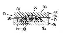
도 6, 도 7 및 도 8은 상부 플라토(16)와 하부 플라토(18)를 포함하여 이루어지는 추간판 보철물(10)을 나타내는데, 하부 플라토는 구형 볼록 돔부(27)를 일체로 포함하여, 상부 플라토(16)에 배치된 보완 임프레션(complementary impression)과 함께 작용하게 된다.6, 7 and 8 show an
본 명세서의 내용에 포함되어 있음.Included in the content of this specification.
Claims (11)
Translated fromKoreanApplications Claiming Priority (3)
| Application Number | Priority Date | Filing Date | Title |
|---|---|---|---|
| FR0602226 | 2006-03-14 | ||
| FR0602226AFR2898487B1 (en) | 2006-03-14 | 2006-03-14 | PROSTHETICS OF INTERVERTEBRAL DISCS |
| PCT/FR2007/000434WO2007104860A1 (en) | 2006-03-14 | 2007-03-13 | Intervertebral disc prostheses |
Publications (2)
| Publication Number | Publication Date |
|---|---|
| KR20090007696A KR20090007696A (en) | 2009-01-20 |
| KR101352546B1true KR101352546B1 (en) | 2014-02-17 |
Family
ID=37401605
Family Applications (1)
| Application Number | Title | Priority Date | Filing Date |
|---|---|---|---|
| KR1020087024503AActiveKR101352546B1 (en) | 2006-03-14 | 2007-03-13 | Intervertebral Disc Prostheses |
Country Status (11)
| Country | Link |
|---|---|
| US (1) | US8790404B2 (en) |
| EP (1) | EP1993484B1 (en) |
| JP (1) | JP5202341B2 (en) |
| KR (1) | KR101352546B1 (en) |
| CN (2) | CN103211669A (en) |
| BR (1) | BRPI0708878A2 (en) |
| CA (1) | CA2645096A1 (en) |
| ES (1) | ES2746176T3 (en) |
| FR (1) | FR2898487B1 (en) |
| MX (1) | MX2008011725A (en) |
| WO (1) | WO2007104860A1 (en) |
Families Citing this family (13)
| Publication number | Priority date | Publication date | Assignee | Title |
|---|---|---|---|---|
| FR2871366A1 (en) | 2004-06-09 | 2005-12-16 | Ceravic Soc Par Actions Simpli | PROSTHETIC EXPANSIBLE BONE IMPLANT |
| CA3020928C (en) | 2008-05-15 | 2023-08-08 | National Research Council Of Canada | Expression systems encoding truncated ebna1, methods, and use thereof |
| FR2935896B1 (en)* | 2008-09-17 | 2011-11-25 | Tural | PROSTHESIS DISCALE IN POLYETHERETHERCETONE. |
| EP2405835B1 (en)* | 2009-03-12 | 2017-11-15 | Vexim | Apparatus for bone restoration of the spine |
| CA2706233C (en) | 2009-06-04 | 2015-05-05 | Howmedica Osteonics Corp. | Orthopedic peek-on-polymer bearings |
| US9173748B2 (en) | 2009-08-07 | 2015-11-03 | Ebi, Llc | Toroid-shaped spinal disc |
| US20110035010A1 (en)* | 2009-08-07 | 2011-02-10 | Ebi, Llc | Toroid-shaped spinal disc |
| KR101192468B1 (en)* | 2011-04-13 | 2012-10-17 | 뉴모텍(주) | Bus-bar connection for improving coil connection and electric conduction reliability |
| WO2014008362A1 (en)* | 2012-07-06 | 2014-01-09 | TrueMotion Spine, Inc. | A shock absorbing, total disc replacement prosthetic |
| KR101397192B1 (en)* | 2013-12-18 | 2014-05-19 | 윤홍원 | Intervertebral tentional artificial disc replacement |
| KR102493783B1 (en) | 2016-01-21 | 2023-02-02 | 한온시스템 주식회사 | Magmate terminal for electric compressor |
| US11452618B2 (en) | 2019-09-23 | 2022-09-27 | Dimicron, Inc | Spinal artificial disc removal tool |
| CN114533350A (en)* | 2022-01-27 | 2022-05-27 | 北京大学第三医院(北京大学第三临床医学院) | Artificial intervertebral disc prosthesis |
Citations (4)
| Publication number | Priority date | Publication date | Assignee | Title |
|---|---|---|---|---|
| KR20010051919A (en)* | 1999-11-24 | 2001-06-25 | 디퍼이 아크로메드 인코포레이티드 | Prosthetic implant element |
| KR20040002729A (en)* | 2002-06-27 | 2004-01-07 | 디퍼이 아크로메드 인코포레이티드 | Intervertebral disc having translation |
| KR20050081143A (en)* | 2004-02-13 | 2005-08-18 | 주식회사 바이오스마트 | Interposition for replacing of intervertebral discs |
| KR20060005339A (en)* | 2005-06-17 | 2006-01-17 | 신세스 게엠바하 | Intervertebral implant |
Family Cites Families (28)
| Publication number | Priority date | Publication date | Assignee | Title |
|---|---|---|---|---|
| CH671691A5 (en)* | 1987-01-08 | 1989-09-29 | Sulzer Ag | |
| FR2775587B1 (en) | 1998-03-03 | 2001-10-19 | Hassan Razian | ADJUSTABLE DISC / SHOCK ABSORBER AND ITS POSTERIOR SYSTEM |
| FR2787014B1 (en)* | 1998-12-11 | 2001-03-02 | Dimso Sa | INTERVERTEBRAL DISC PROSTHESIS WITH REDUCED FRICTION |
| US6368350B1 (en)* | 1999-03-11 | 2002-04-09 | Sulzer Spine-Tech Inc. | Intervertebral disc prosthesis and method |
| FR2799116B1 (en)* | 1999-09-30 | 2002-03-01 | Euros Sa | INTERVERTEBRAL IMPLANT |
| FR2824261B1 (en)* | 2001-05-04 | 2004-05-28 | Ldr Medical | INTERVERTEBRAL DISC PROSTHESIS AND IMPLEMENTATION METHOD AND TOOLS |
| DE50210270D1 (en)* | 2002-03-12 | 2007-07-19 | Cervitech Inc | Intervertebral prosthesis, especially for the cervical spine |
| US20040093082A1 (en)* | 2002-04-19 | 2004-05-13 | Ferree Bret A. | Mobile-bearing artificial disc replacement |
| US20040030391A1 (en)* | 2002-04-24 | 2004-02-12 | Bret Ferree | Artificial intervertebral disc spacers |
| US7001433B2 (en) | 2002-05-23 | 2006-02-21 | Pioneer Laboratories, Inc. | Artificial intervertebral disc device |
| EP1542626B1 (en)* | 2002-08-15 | 2012-09-26 | Synthes GmbH | Controlled artificial intervertebral disc implant |
| CA2495404C (en)* | 2002-08-15 | 2011-05-03 | Justin K. Coppes | Intervertebral disc implant |
| FR2846550B1 (en)* | 2002-11-05 | 2006-01-13 | Ldr Medical | INTERVERTEBRAL DISC PROSTHESIS |
| US7150581B2 (en)* | 2002-11-18 | 2006-12-19 | Lowe Clifford A | Lane marker masking system |
| US20040143334A1 (en)* | 2003-01-08 | 2004-07-22 | Ferree Bret A. | Artificial disc replacements (ADRS) with features to enhance longevity and prevent extrusion |
| WO2004105655A1 (en)* | 2003-06-02 | 2004-12-09 | Impliant Ltd. | Spinal disc prosthesis |
| US7153325B2 (en)* | 2003-08-01 | 2006-12-26 | Ultra-Kinetics, Inc. | Prosthetic intervertebral disc and methods for using the same |
| US20050187633A1 (en)* | 2003-11-10 | 2005-08-25 | Ferree Bret A. | Modular artificial disc replacements (ADRS) that allow translocation and axial rotation |
| US7588600B2 (en)* | 2003-12-10 | 2009-09-15 | Axiomed Spine Corporation | Method for replacing a damaged spinal disc |
| US7250060B2 (en)* | 2004-01-27 | 2007-07-31 | Sdgi Holdings, Inc. | Hybrid intervertebral disc system |
| US7468076B2 (en)* | 2004-02-20 | 2008-12-23 | Spinecore, Inc. | Artificial intervertebral disc having a universal joint |
| US7491239B2 (en)* | 2005-02-23 | 2009-02-17 | Joint Synergy, Llc | Interior insert ball and dual socket joint |
| FR2869528B1 (en)* | 2004-04-28 | 2007-02-02 | Ldr Medical | INTERVERTEBRAL DISC PROSTHESIS |
| DE202004009542U1 (en)* | 2004-06-16 | 2004-08-12 | Aesculap Ag & Co. Kg | Artificial intervertebral disk, comprising core with intensely curved upper and less curved lower surface |
| US20060041314A1 (en)* | 2004-08-20 | 2006-02-23 | Thierry Millard | Artificial disc prosthesis |
| EP1712207B1 (en)* | 2005-04-15 | 2012-05-09 | Eden Spine Europe SA | Intervertebral disc |
| US20080228275A1 (en)* | 2007-03-14 | 2008-09-18 | Heather Cannon | Intervertebral implant component with three points of contact |
| FR2929105B1 (en)* | 2008-03-25 | 2010-04-02 | Medicrea International | PROSTHESIS OF VERTEBRAL DISC, IN PARTICULAR FOR CERVICAL VERTEBRATES |
- 2006
- 2006-03-14FRFR0602226Apatent/FR2898487B1/enactiveActive
- 2007
- 2007-03-13JPJP2008558848Apatent/JP5202341B2/enactiveActive
- 2007-03-13BRBRPI0708878-7Apatent/BRPI0708878A2/ennot_activeApplication Discontinuation
- 2007-03-13CACA002645096Apatent/CA2645096A1/ennot_activeAbandoned
- 2007-03-13CNCN2013100760039Apatent/CN103211669A/enactivePending
- 2007-03-13CNCNA200780009282XApatent/CN101404956A/enactivePending
- 2007-03-13KRKR1020087024503Apatent/KR101352546B1/enactiveActive
- 2007-03-13USUS12/282,883patent/US8790404B2/enactiveActive
- 2007-03-13MXMX2008011725Apatent/MX2008011725A/ennot_activeApplication Discontinuation
- 2007-03-13ESES07731130Tpatent/ES2746176T3/enactiveActive
- 2007-03-13WOPCT/FR2007/000434patent/WO2007104860A1/enactiveApplication Filing
- 2007-03-13EPEP07731130.6Apatent/EP1993484B1/enactiveActive
Patent Citations (4)
| Publication number | Priority date | Publication date | Assignee | Title |
|---|---|---|---|---|
| KR20010051919A (en)* | 1999-11-24 | 2001-06-25 | 디퍼이 아크로메드 인코포레이티드 | Prosthetic implant element |
| KR20040002729A (en)* | 2002-06-27 | 2004-01-07 | 디퍼이 아크로메드 인코포레이티드 | Intervertebral disc having translation |
| KR20050081143A (en)* | 2004-02-13 | 2005-08-18 | 주식회사 바이오스마트 | Interposition for replacing of intervertebral discs |
| KR20060005339A (en)* | 2005-06-17 | 2006-01-17 | 신세스 게엠바하 | Intervertebral implant |
Also Published As
| Publication number | Publication date |
|---|---|
| CN101404956A (en) | 2009-04-08 |
| KR20090007696A (en) | 2009-01-20 |
| ES2746176T3 (en) | 2020-03-05 |
| WO2007104860A1 (en) | 2007-09-20 |
| MX2008011725A (en) | 2008-11-14 |
| JP5202341B2 (en) | 2013-06-05 |
| FR2898487A1 (en) | 2007-09-21 |
| US20090088856A1 (en) | 2009-04-02 |
| CA2645096A1 (en) | 2007-09-20 |
| CN103211669A (en) | 2013-07-24 |
| BRPI0708878A2 (en) | 2011-06-14 |
| EP1993484B1 (en) | 2019-07-17 |
| FR2898487B1 (en) | 2008-11-14 |
| JP2009529934A (en) | 2009-08-27 |
| US8790404B2 (en) | 2014-07-29 |
| EP1993484A1 (en) | 2008-11-26 |
Similar Documents
| Publication | Publication Date | Title |
|---|---|---|
| KR101352546B1 (en) | Intervertebral Disc Prostheses | |
| KR100701991B1 (en) | Intervertebral Implant | |
| US7828846B2 (en) | Space keeper for vertebrae or intervertebral disks | |
| US7887590B2 (en) | Intervertebral disc prosthesis | |
| US8021427B2 (en) | Intervertebral disk prosthesis with elastomeric insert | |
| US8685101B2 (en) | Implant with compliant layer | |
| US20100042150A1 (en) | Intervertebral prosthetic device for spinal stabilization and method of manufacturing same | |
| US20030208271A1 (en) | Artificial disc | |
| US20050038515A1 (en) | Lumbar composite nucleus | |
| US20020143331A1 (en) | Inter-spinous process implant and method with deformable spacer | |
| KR20070108198A (en) | Intervertebral Prosthetic Disc with Shock Absorption | |
| EP3069694A1 (en) | Spinal spacer | |
| US7842089B2 (en) | Intervertebral disc prosthesis | |
| US9144502B1 (en) | Spinal interbody device | |
| US20160270928A1 (en) | Spinal spacer | |
| KR102484143B1 (en) | Artificial disc | |
| US20110022177A1 (en) | Intervertebral filling for cervical vertebrae | |
| CN217338995U (en) | Firmly connected elastic artificial intervertebral disc | |
| JP2012517871A (en) | Intervertebral disc prosthesis | |
| KR102355931B1 (en) | Artificial disc and method for manufacturing the same | |
| AU2005229466A1 (en) | Artificial intervertebral disk | |
| KR102864951B1 (en) | Interbody Fusion prosthesis |
Legal Events
| Date | Code | Title | Description |
|---|---|---|---|
| PA0105 | International application | Patent event date:20081007 Patent event code:PA01051R01D Comment text:International Patent Application | |
| PG1501 | Laying open of application | ||
| A201 | Request for examination | ||
| PA0201 | Request for examination | Patent event code:PA02012R01D Patent event date:20120313 Comment text:Request for Examination of Application | |
| E902 | Notification of reason for refusal | ||
| PE0902 | Notice of grounds for rejection | Comment text:Notification of reason for refusal Patent event date:20130628 Patent event code:PE09021S01D | |
| E701 | Decision to grant or registration of patent right | ||
| PE0701 | Decision of registration | Patent event code:PE07011S01D Comment text:Decision to Grant Registration Patent event date:20131229 | |
| GRNT | Written decision to grant | ||
| PR0701 | Registration of establishment | Comment text:Registration of Establishment Patent event date:20140110 Patent event code:PR07011E01D | |
| PR1002 | Payment of registration fee | Payment date:20140113 End annual number:3 Start annual number:1 | |
| PG1601 | Publication of registration | ||
| FPAY | Annual fee payment | Payment date:20161226 Year of fee payment:4 | |
| PR1001 | Payment of annual fee | Payment date:20161226 Start annual number:4 End annual number:4 | |
| FPAY | Annual fee payment | Payment date:20181226 Year of fee payment:6 | |
| PR1001 | Payment of annual fee | Payment date:20181226 Start annual number:6 End annual number:6 | |
| FPAY | Annual fee payment | Payment date:20191226 Year of fee payment:7 | |
| PR1001 | Payment of annual fee | Payment date:20191226 Start annual number:7 End annual number:7 | |
| PR1001 | Payment of annual fee | Payment date:20220104 Start annual number:9 End annual number:9 | |
| PR1001 | Payment of annual fee | Payment date:20230110 Start annual number:10 End annual number:10 | |
| PR1001 | Payment of annual fee | Payment date:20240108 Start annual number:11 End annual number:11 | |
| PR1001 | Payment of annual fee | Payment date:20250102 Start annual number:12 End annual number:12 |